EP2562339A2 - Vehicle door fixing apparatus and fixed wedge of same - Google Patents
Vehicle door fixing apparatus and fixed wedge of same Download PDFInfo
- Publication number
- EP2562339A2 EP2562339A2 EP20120181451 EP12181451A EP2562339A2 EP 2562339 A2 EP2562339 A2 EP 2562339A2 EP 20120181451 EP20120181451 EP 20120181451 EP 12181451 A EP12181451 A EP 12181451A EP 2562339 A2 EP2562339 A2 EP 2562339A2
- Authority
- EP
- European Patent Office
- Prior art keywords
- wedge
- attachment member
- fixed
- attachment
- vehicle
- Prior art date
- Legal status (The legal status is an assumption and is not a legal conclusion. Google has not performed a legal analysis and makes no representation as to the accuracy of the status listed.)
- Granted
Links
- 230000007246 mechanism Effects 0.000 claims description 37
- 238000011144 upstream manufacturing Methods 0.000 claims description 6
- 239000011347 resin Substances 0.000 description 16
- 229920005989 resin Polymers 0.000 description 16
- 239000000463 material Substances 0.000 description 15
- 239000002184 metal Substances 0.000 description 13
- 230000002829 reductive effect Effects 0.000 description 11
- 230000004308 accommodation Effects 0.000 description 7
- 238000005452 bending Methods 0.000 description 4
- 230000002159 abnormal effect Effects 0.000 description 3
- 238000003780 insertion Methods 0.000 description 3
- 230000037431 insertion Effects 0.000 description 3
- 230000007423 decrease Effects 0.000 description 2
- 230000003247 decreasing effect Effects 0.000 description 2
- 230000000694 effects Effects 0.000 description 2
- 230000004048 modification Effects 0.000 description 2
- 238000012986 modification Methods 0.000 description 2
- 238000000465 moulding Methods 0.000 description 2
- 239000003086 colorant Substances 0.000 description 1
- 230000002542 deteriorative effect Effects 0.000 description 1
- 230000002452 interceptive effect Effects 0.000 description 1
- 230000013011 mating Effects 0.000 description 1
- 239000007769 metal material Substances 0.000 description 1
- 230000000717 retained effect Effects 0.000 description 1
- 230000002441 reversible effect Effects 0.000 description 1
- 229920002379 silicone rubber Polymers 0.000 description 1
Images







Classifications
-
- E—FIXED CONSTRUCTIONS
- E05—LOCKS; KEYS; WINDOW OR DOOR FITTINGS; SAFES
- E05B—LOCKS; ACCESSORIES THEREFOR; HANDCUFFS
- E05B77/00—Vehicle locks characterised by special functions or purposes
- E05B77/36—Noise prevention; Anti-rattling means
-
- E—FIXED CONSTRUCTIONS
- E05—LOCKS; KEYS; WINDOW OR DOOR FITTINGS; SAFES
- E05B—LOCKS; ACCESSORIES THEREFOR; HANDCUFFS
- E05B85/00—Details of vehicle locks not provided for in groups E05B77/00 - E05B83/00
- E05B85/04—Strikers
- E05B85/045—Strikers for bifurcated bolts
-
- E—FIXED CONSTRUCTIONS
- E05—LOCKS; KEYS; WINDOW OR DOOR FITTINGS; SAFES
- E05C—BOLTS OR FASTENING DEVICES FOR WINGS, SPECIALLY FOR DOORS OR WINDOWS
- E05C17/00—Devices for holding wings open; Devices for limiting opening of wings or for holding wings open by a movable member extending between frame and wing; Braking devices, stops or buffers, combined therewith
- E05C17/02—Devices for holding wings open; Devices for limiting opening of wings or for holding wings open by a movable member extending between frame and wing; Braking devices, stops or buffers, combined therewith by mechanical means
- E05C17/54—Portable devices, e.g. wedges; wedges for holding wings open or closed
-
- E—FIXED CONSTRUCTIONS
- E05—LOCKS; KEYS; WINDOW OR DOOR FITTINGS; SAFES
- E05B—LOCKS; ACCESSORIES THEREFOR; HANDCUFFS
- E05B15/00—Other details of locks; Parts for engagement by bolts of fastening devices
- E05B15/02—Striking-plates; Keepers; Bolt staples; Escutcheons
- E05B15/0205—Striking-plates, keepers, staples
- E05B15/022—Striking-plates, keepers, staples movable, resilient or yieldable
-
- E—FIXED CONSTRUCTIONS
- E05—LOCKS; KEYS; WINDOW OR DOOR FITTINGS; SAFES
- E05B—LOCKS; ACCESSORIES THEREFOR; HANDCUFFS
- E05B79/00—Mounting or connecting vehicle locks or parts thereof
- E05B79/02—Mounting of vehicle locks or parts thereof
Definitions
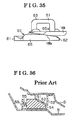
- a known vehicle door fixing apparatus is disclosed in JPHI-43298Y (hereinafter referred to as Reference 1). As illustrated In Fig. 36 , the known vehicle door fixing apparatus disclosed in Reference 1 is provided with a fixed wedge 52 including an inclined surface 51 and fixedly attached to a door panel D. The known vehicle door fixing apparatus is also provided with a movable wedge 54 including an inclined surface 53 being in contact with the inclined surface 51 in a state where a vehicle door is closed. The movable wedge 54 is provided at a vehicle body panel B so as to move in a reciprocating sliding manner. The movable wedge 54 is biased by a spring 55 so as to be pressed against the fixed wedge 52 when the vehicle door is closed; thereby, the door is pushed toward a hinge of the vehicle door.
- the movable wedge 54 is slidably provided on an end surface (upper surface) of a base plate 56 fixedly attached to the vehicle body panel B.
- the end surface of the base plate 56 faces the vehicle door (the fixed wedge 52).
- the fixed wedge 52 is directly fixed to the door panel D.
- the fixed wedge 52 may not be easily or simply replaced with the new fixed wedge 52.
- the fixed wedge 52 welded to the door panel D may not be substantially replaced with the new fixed wedge 52.
- a frictional engagement force between the movable wedge 54 and the fixed wedge 52 may not be easily adjusted, that is, fixing strength of the vehicle door relative to a vehicle body may not be easily adjusted.
- a vehicle door fixing apparatus includes a fixed wedge fixed to one of a vehicle body panel and a door panel, and a wedge device fixed to the other of the vehicle body panel and the door panel, the fixed wedge including an attachment member attached to the vehicle body panel or the door panel, and a wedge member provided to be pressure contactable with the wedge device and being attachable and removable relative to the attachment member, the wedge member forming a design surface of the fixed wedge.
- the fixed wedge includes a fixed-wedge guide rail arranged at one of the attachment member and the wedge member, and a fixed-wedge guide groove arranged at the other of the attachment member and the wedge member, the fixed-wedge guide groove slidably engaging with the fixed-wedge guide rail to guide the wedge member to be attached to and removed from the attachment member.
- the wedge member in the case of attaching the wedge member to the attachment member, the wedge member is shifted to the attachment position relative to the attachment member. Therefore, the second locking portion is engaged with the first locking portion; thereby, the wedge member is restricted from further moving in the attaching direction relative to the attachment member. As a result, the wedge member may be restricted from excessively moving beyond the intended attachment position in the attaching direction relative to the attachment member.
- the fixed wedge includes an engagement convex portion arranged at one of the attachment member and the wedge member and an engagement recessed portion arranged at the other of the attachment member and the wedge member.
- the engagement recessed portion is fitted to the engagement convex portion to restrict the wedge member from moving in a removing direction of the wedge member relative to the attachment member along the sliding direction of the fixed-wedge guide rail and the fixed-wedge guide groove.
- the engagement convex portion is fitted to the engagement recessed portion when the wedge member is arranged at the attachment position relative to the attachment member. Therefore, the wedge member may be restricted from moving relative to the attachment member in the aforementioned attaching direction. As a result, the wedge member arranged at the attachment position relative to the attachment member may be restricted from loosening from the attachment member,
- the fixed wedge is not configured by a single component but is configured by separate components of the attachment member and the wedge member. Therefore, the wedge member may be smoothly attached to and detached from the attachment member by the guide mechanism.
- the wedge member that may exert the desired frictional engagement force is selected and is thereafter fitted to the attachment member; thereby, the frictional engagement force of the fixed wedge with the wedge device may be easily adjusted.
- the fixing strength of the vehicle door relative to the vehicle body may be easily adjusted.
- the attaching and removing directions of the wedge member relative to the attachment member are established to be different from the moving direction of the vehicle door relative to the vehicle body. Therefore, the wedge member may be restricted from being accidentally detached from the attachment member, for example, when the vehicle door is being operated to closed and opened positions.
- the fixed wedge includes a positioning mechanism stopping a movement of the wedge member at an attachment completion position relative to the attachment member when the wedge member is being attached to the attachment member in a direction in which the wedge member is guided by the guide mechanism.
- the movement of the wedge member is stopped at the attachment completion position by the positioning mechanism.
- the wedge member may be restricted from excessively moving; therefore, the vehicle door may be fixed to the vehicle body in an appropriate manner in accordance with the frictional engagement between the wedge member of the fixed wedge and the wedge device when the wedge member is at the attachment completion position.
- the wedge member in the case of attaching the wedge member to the attachment member, the wedge member is brought into contact with the inner surface of the receiving portion arranged at the lowermost position of the attachment member; thereby, a position of the wedge member relative to the attachment member is determined.
- the vehicle door may be appropriately fixed relative to the vehicle door in accordance with the frictional engagement between the wedge member of the fixed wedge and the wedge device when the wedge member is in contact with the receiving portion arranged at the lowermost position of the attachment member.
- the vehicle door fixing apparatus further includes a hanging portion provided at an uppermost position in the attaching direction of the wedge member relative to the attachment member, the hanging portion including an opening opened toward a downstream side in the attaching direction and an inner surface positioned at an upstream side of the opening in the attaching direction, the hanging portion bringing the inner surface into contact with the attachment member to restrict the wedge member from moving in accordance with the attaching of the wedge member to the attachment member in the attaching direction.
- the inner surface of the hanging portion arranged at the uppermost position of the wedge member is brought into contact with the attachment member; thereby, the position of the wedge member relative to the attachment member is determined.
- the vehicle door may be appropriately fixed relative to the vehicle body in accordance with the frictional engagement between the wedge member of the fixed wedge and the wedge device when the hanging portion arranged at the uppermost position of wedge member is in contact with the attachment member.
- the attachment member is attached to the vehicle body panel or the door panel together with a door lock assembly by a same fixing member, the door lock assembly being engageable with a door lock striker fixed to the vehicle body panel or the door panel at which the wedge device is arranged.
- a special attachment portion for attaching the attachment member to the door panel is not required to be provided at the door panel. Consequently, for example, in a case where the attachment member (the fixed wedge) is additionally attached to the door panel after the door lock assembly is attached to the door panel, man-hours required to additionally attach the attachment member to the door panel may be reduced.
- a fixed wedge fixed to one of a vehicle body panel and a door panel
- the fixed wedge including an attachment member attached to the vehicle body panel or the door panel, and a wedge member provided to be pressure contactable with a wedge device arranged at the other of the vehicle body panel and the door panel, the wedge member being attachable and removable relative to the attachment member and forming a design surface of the fixed wedge.
- the fixed wedge is not configured by a single component but is configured by separate components of the attachment member and the wedge member. Therefore, the wedge member may be smoothly attached to and detached from the attachment member by the guide mechanism.
- the wedge member that may exert the desired frictional engagement force is selected and is thereafter fitted to the attachment member; thereby, the frictional engagement force of the fixed wedge with the wedge device may be easily adjusted.
- the fixing strength of the vehicle door relative to the vehicle body may be easily adjusted.
- the attaching and removing directions of the wedge member relative to the attachment member are established to be different from the moving direction of the vehicle door relative to the vehicle body. Therefore, the wedge member may be restricted from being accidentally detached from the attachment member, for example, when the vehicle door is being operated to closed and opened positions.
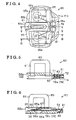
- Fig. 5 is a cross-sectional view taken along the line V-V of Fig. 4 ;
- Fig. 6 is a cross-sectional view taken along the line Vl-Vl of Fig. 4 ;
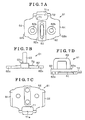
- Fig. 7A is a top plan view of a door lock striker provided at the movable wedge device according to the first embodiment disclosed here;
- Fig. 7B is a front view of the door lock striker provided at the movable wedge device according to the first embodiment disclosed here;
- Fig. 7C is a bottom plan view of the door lock striker provided at the movable wedge device according to the first embodiment disclosed here;
- Fig. 7D is a side view of the door lock striker provided at the movable wedge device according to the first embodiment disclosed here;
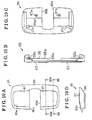
- Fig. 8B is a top plan view of the cover to be attached to the door lock striker of the first embodiment disclosed here;
- Fig. 9 is a cross-sectional view taken along the line lX-lX of Fig. 8 ;
- Fig. 10A is a top plan view of a movable wedge to be provided at the movable wedge device according to the first embodiment disclosed here;
- Fig. 10B is a front view of the movable wedge to be provided at the movable wedge device according to the first embodiment disclosed here;
- Fig. 10C is a bottom plan view of the movable wedge to be provided at the movable wedge device according to the first embodiment disclosed here;
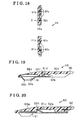
- Fig. 11A is a cross-sectional view take along the line XIA-XIA of Fig. 10A ;
- Fig. 11B is an enlarged view of a portion of Fig. 11A ;
- Fig. 11C is an enlarged view of a portion of Fig. 11A ;
- Fig.12 is a cross-sectianal view taken along the line XII-XII of Fig. 10A :
- Fig. 13 is a plan view illustrating a movement of the movable wedge device according to the first embodiment disclosed here;
- Fig. 14 is a plan view of the movable wedge device according to the first embodiment before the movable wedge device is assembled on a vehicle body panel;
- Fig. 16 is an exploded perspective view of a fixed wedge to be provided at the vehicle door fixing apparatus according to the first embodiment disclosed here;
- Fig. 17 is a plan view of the fixed wedge according to the first embodiment disclosed here;
- Fig. 18 is a cross-sectional view taken along the line XVIII-XVIII of Fig. 17 ;
- Fig. 19 is a cross-sectional view taken along the line XIX-XIX of Fig. 17 ;
- Fig. 20 is a cross-seetional view taken along the line XX-XX of Fig. 17 ;
- Fig. 21 is a perspective view illustrating a state where an attachment member of the fixed wedge according to the first embodiment disclosed here is attached to a door panel;
- Fig. 22 is a perspective view illustrating a state where the fixed wedge of the first embodiment disclosed here is attached to the door panel;
- Fig. 23 is a cross-sectional side view illustrating a state where the fixed wedge according to the first embodiment is assembled on the door panel;
- Fig. 24 is a side view illustrating a state of the movable wedge device and the fixed wedge of the vehicle door fixing apparatus according to the first embodiment when a vehicle body is not deformed;
- Fig. 25 is a side view illustrating a state of the movable wedge device and the fixed wedge of the vehicle door fixing apparatus according to the first embodiment when the vehicle body is deformed;
- Fig. 26 a cross-sectional side view of the vehicle door fixing apparatus according to a second embodiment disclosed here;
- Fig. 27 is an exploded perspective view of a fixed wedge to be provided at the vehicle door fixing apparatus according to the second embodiment disclosed here;
- Fig. 28 is a plan view of the fixed wedge according to the second embodiment disclosed here;
- Fig. 29 is a cross-sectional view taken along the line XXIX-XXIX of Fig. 28 ;
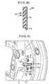
- Fig. 32 is a perspective view illustrating a state where the fixed wedge of the second embodiment disclosed here is assembled on the door panel;
- Fig. 34 is a side view illustrating a state where the movable wedge device and the fixed wedge of the vehicle door fixing apparatus according to the second embodiment when the vehicle body is not deformed;
- Fig. 35 is a side view illustrating a state where the movable wedge device and the fixed wedge of the vehicle door fixing apparatus according to the second embodiment when the vehicle body is deformed;
- Fig. 36 is a cross-sectional side view of a known vehicle door fixing apparatus.
- a first embodiment of this disclosure will be explained as follows with reference to the illustrations of Figs. 1 to 25 .
- a vehicle door fixing apparatus according to the first embodiment is applied to a side door positioned at a front right side of a vehicle including a vehicle body configured to be completely open to air or at a front right side of a vehicle including a convertible vehicle body.
- a vehicle body panel B (a side member outer panel) forms an end surface B1 and a flange B2.
- the end surface B1 extending in a width direction of the vehicle (the width direction of the vehicle will be hereinafter referred to as a vehicle width direction) and facing a front side of the vehicle is positioned at a rear portion of an opening (a door opening) formed in a side surface of the vehicle body of the vehicle in the vehicle width direction.
- the flange B2 extends from an interior end of the end surface B1 in the vehicle width direction (in a horizontal direction of Fig. 1 ), to the front side of the vehicle.
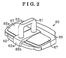
- a movable wedge device 60 (serving as a wedge device) including a door lock striker 61 and a movable wedge 65 is provided at the end surface B1.
- the movable wedge 65 is configured by a strength member 66 made of, for example, a metal material, and a pair of contact members 67 each formed, for example, by a resin panel.
- the strength member 66 has rigidity higher than rigidity of the contact member 67.
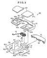
- the movable wedge device 60 includes the door lock striker 61, the movable wedge 65, a spring 76, and a cover 81 fixedly attached to the base plate 62.
- the spring 76 is arranged between the door lock striker 61 and the movable wedge 65.
- a position located away from the cover 81 in a direction in which the upper end portion of the shaft 63 (the door lock striker 61) extends will be hereinafter referred to as a front side of the movable wedge device 60 (the direction corresponds to a diagonally downward left direction in Figs. 2 and 3 ).
- the front side of the movable wedge device 60 (the movable wedge 65) corresponds to an exterior side of the vehicle in the vehicle width direction.
- a guide protruding portion 62a is formed at the base plate 62 of the door lock striker 61 so as to have a substantially rectangular column shape protruding in a protruding direction of the shaft 63.
- the guide protruding portion 62a extends substantially between front and rear end portions of the shaft 63 in a front/rear direction of the door lock striker 61 (the movable wedge device 60) so as to bridge the front and rear end portions of the shaft 63.
- the front and rear portions of the shaft 63 are fixed via the guide protruding portion 62a to the base plate 62 by caulking.
- a pair of locking tabs 62c each formed in a tab is provided at respective front end portions of the guide rails 64 so as to protrude in a direction In which the locking tabs 62c separate from each other in the lateral direction of the movable wedge device 60.
- a stepped portion 72 is formed at a rear end of the base plate 62 so as to be raised upward from an upper surface of the base plate 62 in the protruding direction of the shaft 63.
- the upper surface of the base plate 62 faces the protruding direction of the shaft 63.
- the spring 76 includes a pair of coil portions 76a and arm portions 76b protruding from the respective coil portions 76a.
- the coil portions 76a wound in coiled shapes are provided in a manner that the shaft 63 is sandwiched between the coil portions 76a in the lateral direction of the movable wedge device 60.
- the spring 76 is formed in a bilaterally symmetrical shape relative to the shaft 63.
- the coil portions 76a are wound in reverse directions to each other and are connected to each other in an opposite direction from the protruding direction of the shaft 63.
- the arm portions 76b connecting to the respective coil portions 76a protrude in diagonally forward directions in such a way that end portions of the arm portions 76b gradually separate from each other in the lateral direction of the movable wedge device 60.
- the cover 81 includes an accommodation space 82 for accommodating therein the spring 76 in cooperation with the base plate 62 (the spring accommodating portion 71). As illustrated in Fig. 9 , the accommodation space 82 is formed so as to extend between front and rear ends of the cover 81.
- a tab 83 is formed at a front portion of the cover 81 so as to be positioned between the coil portions 76a.
- a rear end portion of the base plate 62 is fitted to the accommodation space 82 as illustrated in Fig. 6 , and the tab 83 is engaged with the stepped portion 72 of the base plate 62 as shown in Fig. 5 ; thereby, the cover 81 is fixed to the base plate 62.
- Each of the coil portions 76a of the spring 76 includes upper and lower ends facing the protruding direction of the shaft 63 and the opposite direction of the protruding direction of the shaft 63, respectively (see Fig. 3 ).
- the upper and lower ends of the coil portion 76a are supported by opposite facing inner walls of the accommodation space 82.
- a rear end of the coil portion 76a is supported by the rear wall of the spring accommodating portion 71.
- the movable wedge 65 is provided at the base plate 62 so as to cover the upper surface of the base plate 62, which upper surface faces the protruding direction of the shaft 63.
- the strength member 66 of the movable wedge 65 is formed in a substantially rectangular frame.
- a guide groove 66a is formed in a substantially central portion of a front end portion of the strength member 66 so as to extend in the front/rear direction of the movable wedge device 60.
- Guide grooves 66b are formed at both side ends of the strength member 66 in the lateral direction of the movable wedge device 60 so as to extend in the front/rear direction of the movable wedge device 60.
- the strength member 66 (the movable wedge 65) is slidable relative to the base plate 62 in the front/rear direction of the movable wedge device 60, for example, via a pair of rail mechanisms (each of the rail mechanisms is formed by the guide rail 64 and the guide groove 66b).
- an attachment recessed portion 66c is formed at a rear side of the front end portion of the strength member 66.
- the attachment recessed portion 66c is recessed toward the base plate 62 along a lateral direction of the strength member 66 over a substantially entire length thereof.
- a pair of attachment holes 66d are formed in the attachment recessed portion 66c in the lateral direction of the strength member 66 in such a manner that the guide groove 66a is provided between the attachment holes 66d.
- Each of the attachment holes 66d penetrates the strength member 66 in a thickness direction thereof (in the protruding direction of the shaft 63). As illustrated in Figs.
- chamfered portions 66e each having an inclined surface are formed at a front edge of a rear end portion of the strength member 66 so as to be positioned at an intermediate portion of the rear end portion in an extending direction thereof along the lateral direction of the strength member 66.
- the rear end portion of the strength member 66 is configured to be sharpened diagonally toward a front side of the base plate 62 by the chamfered portions 66e.
- the chamfered portions 66e are not formed at side ends of the rear end portion of the strength member 66 in the extending direction and the side ends of the rear end portion form locking portions 66f each standing at a substantially right angle to the base plate 62.
- the pair of contact members 67 of the movable wedge 65 is fixed to the strength member 66 so as to be laid on the attachment recessed portion 66c in a state where the guide groove 66a is provided between the contact members 67.
- an attachment protruding portion 67a is formed at a front end portion of each of the contact members 67 as shown in Figs. 11A and 11B .
- An end portion of the attachment protruding portion 67a having a flanged shape is inserted in the attachment hole 66d so as to penetrate therethrough.
- the attachment protruding portion 67a is locked by an inner circumferential portion of the attachment hole 66d.
- a substantially cylindrical pin P that may penetrate through the attachment hole 66d is welded into the flanged shape, thereby forming the attachment protruding portion 67a.
- the locking tab 67c is formed so as to protrude rearward in a contact manner with an end surface of the locking portion 66f, which end surface faces the base plate 62. Accordingly, the chamfered portion 67b and the locking tab 67c of the contact member 67 are in contact with the chamfered portion 66e of the strength member 66 and the end surface of the locking portion 66f of the strength member 66, respectively.
- each of the contact members 67 is moved rearward relative to the strength member 66; thereby, the front edge of the rear end portion of the strength member 66 is pressed by the chamfered portion 67b and the locking tab 67c so as to be sandwiched between the chamfered portion 67b and the locking tab 67c in the thickness direction of the strength member 66.
- the contact member 67 is pivoted about a pivot point, for example, the chamfered portion 67b, toward the strength member 66 in the thickness direction thereof while the pin P is inserted in the attachment recessed portion 66c to be laid thereon.
- the end portion of the pin P is inserted through the attachment hole 66d and is welded so as to have the flanged shape; thereby, the attachment protruding portion 67a is formed.
- the contact members 67 are fixedly attached to the strength member 66 and are restricted from loosening from the strength member 66.
- the movable wedge 65 includes an inclined surface 65a.
- the inclined surface 65a is formed to be located at the respective front end portions of the contact members 67 fixed to the strength member 66.
- the inclined surface 65a becomes close to the strength member 66 in the thickness direction thereof.
- the movable wedge 65 also includes a slit 65b cut from the front side of the movable wedge 65.
- the guide groove 66a of the strength member 66 slides relative to the guide protruding portion 62a of the base plate 62 from the rear side to the front side of the base plate 62 while the guide grooves 66b are being slid along the guide rails 64 formed at the side edges of the base plate 62 in the lateral direction thereof.
- the arm portions 76b each protruding diagonally toward the front side of the movable wedge device 60 are pressed against a rear end surface 66g of the front end portion of the strength member 66 as shown in Figs.
- the strength member 66 is consistently biased relative to the base plate 62 toward the front side of the movable wedge device 60 so that the front edge of the rear end portion of the strength member 66 is brought into contact with a rear end surface of the guide protruding portion 62a of the base plate 62 or so that respective front end surfaces of the guide grooves 66b are brought into contact with the locking tabs 62c of the base plate 62.
- the rear end portion of the base plate 62 is fitted to the accommodation space 82 of the cover 81 and the tab 83 is engaged with the stepped portion 72 of the base plate 62; thereby, the cover 81 is fixed to the base plate 62.
- the upper end of each of the coil portions 76a which upper end faces the protruding direction of the shaft 63
- the lower end of each of the coil portions 76a. which lower end faces the opposite direction of the protruding direction of the shaft 63 are supported by the opposite facing inner walls of the accommodation space 82.
- the rear end of each of the coil portions 76a is supported by the rear wall of the spring accommodating portion 71.
- the bolt holes 62b may be exposed in a direction in which the bolts are inserted in the bolt holes 62b, respectively.
- the movable wedge device 60 having the above-explained configuration is fixedly attached to the end surface B1 of the vehicle body panel B.
- a direction in which the upper end portion of the shaft 63 (the door lock striker 61) extends that is, the front/rear direction of the movable wedge device 60 and a moving direction of the movable wedge 65, coincides with the vehicle width direction.
- the moving direction of the movable wedge 65 coincides with a direction in which the door panel D is moved close to and away from the vehicle body panel B in accordance with opening and closing operations of the vehicle door.
- the movable wedge 65 (the strength member 66) surrounds the shaft 63 of the door lock striker 61 so that the guide groove 66a is opened to the fixed wedge 68 in the direction in which the door panel D is moved close to and away from the vehicle body panel B.
- the inclined surface 65a is inclined so as to become close to the end surface B1 toward the exterior side in the vehicle width direction.
- the movable wedge 65 is biased by the spring 76 toward the front side of the movable wedge 65 so that the front edge of the rear end portion of the strength member 66 is brought into contact with the rear end surface of the guide protruding portion 62a of the base plate 62 or so that the front end surfaces of the guide grooves 66b are brought into contact with the locking tabs 62c of the base plate 62. Accordingly, the bolt holes 62b (and the bolts inserted therein) are covered by the movable wedge 65 so as not to be exposed to the outside.
- the fixed wedge 68 includes an attachment member 91 made of, for example, a metal plate, and a wedge member 92 made of, for example, a resin material.
- the attachment member 91 integrally includes a body portion 93 and a pair of extending portions 94.
- the body portion 93 includes a groove portion 93a formed into a substantially rectangular shape, therefore being formed in a substantially U-shape.
- the pair of extending portions 94 is formed to extend from an opening of the groove portion 93a toward opposite directions from each other in a lateral direction of the wedge member 92 in a manner that the groove portion 93a is positioned between the extending portions 94.
- the attachment member 91 is symmetrically formed relative to the groove portion 93a.
- a direction to which the substantially U-shape of the body portion 93 (the attachment member 91) is opened corresponds to a front side of the fixed wedge 68 (the aforementioned direction is a diagonally downward left direction in Fig. 16 ).
- the opposite direction of the front side of the fixed wedge 68 corresponds to a rear side of the fixed wedge 68 (the opposite direction of the front side is a diagonally upward right direction in Fig. 16 ).
- the attachment member 91 includes a pair of fixed-wedge guide rails 91 a for engaging with the wedge member 92 and a pair of fixed-wedge guide rails 91 b for engaging with the wedge member 92 (the fixed-wedge guide rails 91 a and 91 b will be hereinafter simply referred to as guide rails 91a and 91b).
- the pair of guide rails 91a is formed at side ends of a rear end portion of the body portion 93 in a lateral direction thereof so as to stand vertically from the body portion 93 and so as to be bent in an extending manner toward each other in the lateral direction, thereby having substantially L-shapes.
- the first locking portions 91c protrude in a direction in which the guide rails 91a and the like protrude.
- a protruding length of each of the first locking portions 91c gradually increases from a rear side to a front side thereof.
- a pair of engagement convex portions 91d is formed at the attachment member 91.
- Each of the engagement convex portions 91d is formed by cutting and raising a rear end portion of each of the extending portions 94 so that the cut portion is folded at a fold line, i,e, a front end of the cut portion, diagonally in the direction in which the first locking portion 91 c Is raised.
- a rear end portion of the engagement convex portion 91 d is bent toward the body portion 93; thereby, the engagement convex portion 91 d has a convex portion.
- recessed portions 94a each having a substantially conical shape are formed in the extending portions 94, respectively.
- Each of the recessed portions 94a serves as a bearing surface for a bolt 96 (see Fig. 21 ) for fixing the attachment member 91 (the fixed wedge 68) to the door panel D.
- a bolt hole 94b into which the bolt 96 is inserted is formed at a substantially center of the recessed portion 94a.
- the bolt hole 94b has a substantially major arc shape opened to the front side of the fixed wedge 68 in order to reduce a size of the attachment member 91 (the pair of extending portions 94) in the front/rear direction of the fixed wedge 68.
- the bolt hole 94b may be completely circular in case where it is not necessary for the size of the attachment member 91 (the pair of extending portions 94) to be reduced in the front/rear direction.
- the wedge member 92 includes a slit 92a cut from the front side to the rear side of the fixed wedge 68 to be formed in a substantially U-shape. As illustrated in Fig. 17 , the wedge member 92 providing a design surface of the fixed wedge 68 is provided attachable and removable relative to the attachment member 91. The wedge member 92 is fixed to the attachment member 91 so as to cover the entire attachment member 91 and so as to face the guide rails 91 b and the like. In other words, as illustrated in Fig.
- the wedge member 92 includes a pair of fixed-wedge guide grooves 92b for engaging with the attachment member 91 and a pair of fixed-wedge guide grooves 92c for engaging with the attachment member 91 (the fixed-wedge guide grooves 92b and 92c will be hereinafter simply referred to as guide grooves 92b and 92c.
- the guide grooves 92b each having a substantially L-shaped cross section and the guide grooves 92c each having a substantially L-shaped cross section slidably engage with the guide rails 91 a and the guide rails 91 b. respectively.
- recessed portions 92d are formed at the wedge member 92.
- Each of the recessed portions 92d is in contact with a portion located at a rear side of the engagement convex portion 91d and including the engagement convex portion 91d.
- the recessed portion 92d includes a convex portion 92e protruding toward the engagement convex portion 91d so as to be in pressure contact with a rear end of the engagement convex portion 91d.
- the convex portion 92e is formed in a substantially triangular cross section.
- the wedge member 92 includes engagement recessed portions 92f each configured by a front end surface of the recessed portion 92d, a front end surface of the convex portion 92e, and an inner wall surface positioned between the front end surface of the recessed portion 92d and the front end surface of the convex portion 92e.
- the engagement convex portion 91d When inserting the engagement convex portion 91d to the recessed portion 92d from a rear end thereof in accordance with a rearward movement of the wedge member 92 relative to the attachment member 91, the engagement convex portion 91d is elastically deformed by the convex portion 92e to be fitted to the engagement recessed portion 92f. Therefore, the wedge member 92 is restricted from moving in the front/rear direction (that is, the sliding movement of the wedge member 92 along a sliding direction of the guide grooves 92b and the guide grooves 92c relative to the guide rails 91 a and the guide rails 91 b is restricted).
- the wedge member 92 is restricted from moving relative to the attachment member 91 in a direction in which the wedge member 92 is removed from the attachment member 91. Additionally, for example, an external force exceeding a certain level is applied to the wedge member 92 attached to the attachment member 91, in the direction in which the wedge member 92 is removed from the attachment member 91. At this time, the engagement convex portion 91d, which may be elastically deformed by the convex portion 92e, moves beyond the convex portion 92e, therefore being detached from the engagement recessed portion 92f. As a result, the wedge member 92 attached to the attachment member 91 may be removed therefrom.
- recessed portions 92g for accommodating therein the first locking portions 91 c are formed at the wedge member 92.
- a front end surface (facing the rear side of the fixed wedge 68) of each of the recessed portions 92g forms a second locking portion 92h while.
- the front end surface of the recessed portion 92g is positioned in the vicinity of the front end surface of the first locking portion 91c c or in contact with the first locking portion 91c in the direction in which the wedge member 92 is attached to the attachment member 91 (i.e., an attaching direction of the wedge member 92 relative to the attachment member 91), thereby providing the second locking portion 92h. Therefore, when attaching the wedge member 92 to the attachment member 91, the wedge member 92 is shifted to the attachment position relative to the attachment member 91 in accordance with the rearward movement of the wedge member 92 relative to the attachment member 91.
- the second locking portion 92h is engaged with the first locking portion 91c; thereby, the wedge member 92 is restricted from further moving rearward, that is, in the attaching direction relative to the attachment member 91.
- the wedge member 92 is restricted from excessively moving relative to the attachment member 91 beyond the intended attachment position in the attaching direction relative to the attachment member 91.
- the fixed wedge 68 includes an inclined surface 68a formed at a front end portion of the wedge member 92 fixed to the attachment member 91.
- the inclined surface 68a is inclined so as to become close to the attachment member 91 in a thickness direction thereof, that is, so as to be inclined diagonally toward the front side of the fixed wedge 68.
- the wedge member 92 is moved from a front side to a rear side of the attachment member 91 as illustrated in Fig. 16 . and the guide rails 91a and the guide rails 91 b of the attachment member 91 are slid along the guide grooves 92b and the guide grooves 92c of the wedge member 92, respectively, as illustrated in Fig. 17 . Further, the engagement convex portions 91 d of the attachment member 91 are slid to the recessed portions 92d of the wedge member 92 respectively, thereafter being fitted to the engagement recessed portions 92f.
- first locking portions 91c of the attachment member 91 are slid to the recessed portions 92g of the wedge member 92, respectively, thereafter being moved close to or being brought into contact with the second locking portions 92h in the aforementioned attaching direction.
- the assembling of the fixed wedge 68 is completed.
- the attachment member 91 In order to mount the fixed wedge 68 to the door panel D (the end surface D1 extending in the vehicle width direction and facing the vehicle body panel B), first, the attachment member 91, without the wedge member 92 attached thereto, is fixedly attached to the end surface D1 as illustrated in Fig. 21 . At this time, the attachment member 91 is attached to the door panel D together with the door lock assembly LA, which is temporarily attached to the door panel D so as to be positioned at the opposite side of the attachment member 91 relative to the door panel D.
- the door lock assembly LA is tightened to the door panel D in advance so as to be positioned at the opposite side of the attachment member 91 relative to the door panel D, by means of a bolt 98 that is arranged at the door panel D so as not to interfere with the attachment member 91 (the fixed wedge 68). Thereafter, the attachment member 91 is fixedly attached to the end surface D1 together with the door lock assembly LA by means of the bolts 96 each serving as a fixing member.
- the groove portion 93a of the attachment member 91 surrounds a portion of a recess D2 formed in the door panel D so as to receive the door lock striker 61 (the portion of the recess D2 extends in the vehicle width direction).
- the groove portion 93a surrounds the portion of the recess D2 while keeping a certain distance relative to the recess D2.
- the shaft 63 of the door lock striker 61 is inserted in and removed from the recess D2.
- the recessed portion 94a of the attachment member 91 of the fixed wedge 68 which recessed portion 94a protrudes toward the end surface D1, is configured to be fitted to a recessed portion 97 formed at the door panel D.
- the wedge member 92 is fixedly attached in the aforementioned manner relative to the attachment member 91 secured to the end surface D1. In such condition, the entire attachment member 91 is covered by the wedge member 92, thereby being restricted from being exposed to the outside. In addition, the bolts 96 for fixing the attachment member 91 to the door panel D are also restricted from being exposed to the outside.
- a direction (an extending direction) in which the slit 92a extends coincides with the direction in which the door panel D is moved close to and away from the vehicle body panel B in accordance with the opening and closing operations of the vehicle door. That is, the extending direction of the slit 92a corresponds to the vehicle width direction in a state where the vehicle door is closed.
- the slit 92a of the fixed wedge 68 (the wedge member 92) is formed in a shape that matches a shape of the portion of the recess D2, which portion extends in a width direction of the recess D2 (in the vehicle width direction in a state where the vehicle door is closed).
- the fixed wedge 68 is configured so that the slit 92a surrounds the recess D2 in an open manner toward the movable wedge device 60 in the direction in which the door panel D is moved close to and away from the vehicle body panel B in accordance with the opening and closing operations of the vehicle door.
- the inclined surface 68a is inclined relative to the body panel B so as to become close to the end surface D1 toward the direction in which the door panel D is moved close to the vehicle body panel B in accordance with the closing operation of the vehicle door (i.e., the inclined surface 68a is inclined relative to the body panel B so as to become close to the end surface D1 toward the interior side of the vehicle in the vehicle width direction).
- the inclined surface 65a of the movable wedge 65 and the inclined surface 68a of the fixed wedge 68 are in pressure contact with each other in a state where the vehicle door is closed.
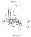
- the vehicle door fixing apparatus of the first embodiment in a state where the vehicle door is closed, the inclined surface 65a of the movable wedge 65 that is arranged at the vehicle body panel B so as to slidably reciprocate relative thereto, is in contact with the inclined surface 68a of the fixed wedge 68 that is fixedly attached to the door panel D (see Fig. 1 ).
- the movable wedge 65 is pressed against the fixed wedge 68 by the biasing force of the spring 76; therefore, the vehicle door is pushed toward a hinge of the vehicle door. As a result, rattles or vibrations of the vehicle door are restricted.
- the movable wedge 65 at a side of the vehicle at which the vehicle body expands moves relative to the fixed wedge 68 in the right direction when viewed in Fig. 24 .
- the movable wedge 65 in a state illustrated in Fig. 24 moves to a state illustrated in Fig. 25 .
- the fixed wedge 68 moves upward when viewed in Fig. 24 (that is, in the longitudinal direction, i.e. a front/rear direction, of the vehicle when the fixed wedge 68 is assembled on the vehicle).
- the wedge member 92 is attachable and removable relative to the attachment member 91. Accordingly, for example, in a case where various types of materials exerting different frictional engagement forces relative to the movable wedge device 60 (the movable wedge 65) are applicable to the wedge member 92 due to a change of the material of the wedge member 92, one of the various materials may be selected to be applied to the wedge member 92 and the wedge member 92 made of the selected material is attached to the attachment member 91.
- a frictional engagement force between the movable wedge device 60 and the fixed wedge 68 may be adjusted depending on preferences of an user of the vehicle, that is, fixing strength of the vehicle door relative to the vehicle body may be arbitrarily adjusted.
- the wedge member 92 is removed from the attachment member 91; therefore, the frictional engagement between the movable wedge device 60 and the fixed wedge 68 may be eliminated depending on the preferences of the user. That is, the wedge member 92 is removed from the attachment member 91; thereby, whether to apply the fixing strength of the vehicle door relative to the vehicle body may be selected accordingly.
- the various wedge members 92 including different design surfaces, for example, having different colors, are selectable, one of the wedge members 92 is selected to be thereby attached to the attachment member 91.
- the design of the wedge member 92 may be improved so as to suit the preference of the user.
- the wedge member 92 may be attached to and removed from the attachment member 91 while the attachment member 91 is maintained in the fixed state to the end surface D1 of the door panel D, Therefore, the wedge member 92 may be smoothly replaced with the new wedge member 92.
- the pair of guide rails 91a and the pair of guide rails 91 b are simply configured to slidably engage with the pair of guide grooves 92b and the pair of guide grooves 92c, respectively; thereby, the wedge member 92 may be attached to and removed from the attachment member 91. As a result, the wedge member 92 may be further smoothly attached to and detached from the attachment member 91.
- the first locking portions 91 c of the attachment member 91 are positioned in adjacent to or in contact with the second locking portions 92h in the aforementioned attaching direction of the wedge member 92 relative to the attachment member 91 (in the rear of the fixed wedge 68) along the sliding direction of the guide grooves 92b and the guide grooves 92c relative to the guide rails 91a and the guide rails 91b.
- the wedge member 92 is shifted to the attachment position relative to the attachment member 91 in accordance with the rearward movement of the wedge member 92 relative to the attachment member 91.
- the second locking portions 92h are engaged with the first locking portions 91 c; thereby, the wedge member 92 is restricted from further moving rearward in the attaching direction relative to the attachment member 91.
- the wedge member 92 is restricted from excessively moving relative to the attachment member 91 beyond the intended attachment position in the attaching direction relative to the attachment member 91.
- the wedge member 92 may be restricted from moving relative to the attachment member 91 in the aforementioned attaching direction corresponding to a pressing direction of the movable wedge device 60 relative to the fixed wedge 68.
- the engagement convex portions 91 d of the attachment member 91 are fitted to the engagement recessed portions 92f of the wedge member 92 when the wedge member 92 is arranged at the attachment position relative to the attachment member 91. Therefore, the wedge member 92 may be restricted from moving relative to the attachment member 91 in the aforementioned attaching direction.
- the wedge member 92 arranged at the attachment position relative to the attachment member 91 may be restricted from loosening from the attachment member 91.
- the external force exceeding the certain level is applied to the wedge member 92 attached to the attachment member 91, in the direction in which the wedge member 92 is removed from the attachment member 91.
- the engagement convex portions 91 d which may be elastically deformed by the convex portions 92e, move beyond the convex portions 92e, Consequently, the engagement convex portions 91d are detached from the engagement recessed portions 92f; therefore, the wedge member 92 attached to the attachment member 91 may be removed therefrom.
- the attachment member 91 is fixedly attached to the door panel D by means of the same bolts 96 as the door lock assembly LA. Accordingly, a special attachment portion for attaching the attachment member 91 to the door panel D is not required to be provided at the door panel D. Consequently, for example, in a case where the attachment member 91 (the fixed wedge 68) is additionally attached to the door panel D after the door lock assembly LA is attached to the door panel D, man-hours required to additionally attach the attachment member 91 to the door panel D may be reduced.
- the movable wedge 65 may be mounted to the vehicle body panel B together with the base plate 62 of the door lock striker 61 and the fixed wedge 68 may be mounted to the door panel D together with the door lock assembly LA. Therefore, man-hours required for assembling the vehicle door fixing apparatus as a whole, including the door lock striker 61 and the like, may be reduced.
- the strength member 66 of the movable wedge 65 includes the guide groove 66a surrounding the shaft 63 of the door lock striker 61 so as to be opened to the fixed wedge 68 in the direction in which the door panel D is moved close to and away from the vehicle body panel B.
- the strength member 66 may be elastically deformed in such a way that a width of an opening of the guide groove 66a is increased in the lateral direction of the strength member 66.
- the strength member 66 has the rigidity higher than that of the pair of contact members 67, therefore being restricted from being elastically deformed.
- the movement of the movable wedge 65 may be further stable.
- each of the contact members 67 is configured so that the chamfered portion 67b and the locking tab 67c face portions (the chamfered portion 66e and the end surface of the locking portion 66f) of the strength member 66 in the direction in which the door panel D is moved close to and away from the vehicle body panel B.
- the chamfered portion 66e and the locking portion 66f which face the chamfered portion 67b and the locking tab 67c, are sandwiched between the chamfered portion 67b and the locking tab 67c in the thickness direction of the strength member 66.
- the contact members 67 are restricted from being detached from the strength member 66.
- the contact members 67 are pressed against the fixed wedge 68; therefore, the contact members 67 may shift in a direction in which the contact members 67 separate from the fixed wedge 68.
- the shifting of the contact members 67 functions to increase overlaps between the chamfered portion 66e and the chamfered portion 67b and between the locking portion 66f and the locking tab 67c. Therefore, the contact members 67 may be restricted from loosening from the strength member 66, in accordance with the pressure contact of the contact members 67 with the fixed wedge 68.
- each of the contact members 67 is configured so that the attachment protruding portion 67a is inserted in the attachment hole 66d, thereby being restricted from loosening in the thickness direction of the strength member 66. Therefore, the contact members 67 are restricted from being detached from the strength member 66.
- the plural coil portions 76a (the two coil portions 76a) of the spring 76 are arranged side by side.
- an external diameter (coil diameter) of each of the coil portions 76a of the spring 76 of the first embodiment may be reduced as compared with a case where a predetermined biasing force is obtained by means of a single coil portion of a spring.
- the size of the base plate 62 including the supporting portion 71a supporting the coil portions 76a, and the size of the cover 81 may be further reduced in the moving direction of the movable wedge 65.
- the base plate 62 (the movable wedge device 60) of the first embodiment may be arranged at the end surface B1 without interfering with the flange B2. Further, the assemblability of the base plate 62 relative to the vehicle may be increased. Furthermore, the movable wedge device 60 (the vehicle door fixing apparatus) of the first embodiment is applicable to various types of vehicles.
- the recessed portions 94a each serving as the bearing surface for the bolt 96 for fixing the attachment member 91 to the door panel D are formed at the attachment member 91 of the fixed wedge 68.
- the bearing surface for the bolt 96 is strengthened by metal (the metal plate of the attachment member 91). Therefore, the fixed wedge 68 may appropriately be restricted from rattling or vibrating due to creep deformation that may be caused by a bolt bearing surface, for example, made of resin.
- the recessed portion 94a of the fixed wedge 68 configures the bearing surface for the bolt 96.
- the recessed portion 94a is configured to extend toward the end surface D1 and to be fitted to the recessed portion 97 formed at the door panel D. Therefore, the position of the fixed wedge 68 relative to the door panel D may be easily determined when fixing the fixed wedge 68 to the end surface D1, thereby increasing the assemblability of the fixed wedge 68 relative to the door panel D (the vehicle).
- the spring 76 is accommodated in the cover 81 and is thereby surrounded by the cover 81. Accordingly, the spring 76 is restricted from shifting and the orientation thereof is prevented from inappropriately changing.
- the cover 81 configured to accommodate the spring 76 as described above is formed as a separate member from the base plate 62, therefore preventing the orientation of the spring 76 from inappropriately changing.
- the shape of the base plate 62 is appropriately restricted from being complicated. As a result, the formability of the base plate 62 may be restricted from deteriorating while the orientation of the spring 76 is prevented from inappropriately changing.
- the supporting portion 71a supporting the coil portions 76a in the opposite direction from the direction in which the arm portions 76b protrude is formed at the base plate 62.
- the cover 81 is provided so as to support the upper and lower ends of each of the coil portions 76a. Therefore, the orientation of the spring 76 may be appropriately maintained.
- the stepped portion 72 is arranged at the base plate 62 and the tab 83 engageable with the stepped portion 72 is arranged at the cover 81. Therefore, the cover 81 may be easily and surely fitted to the base plate 62.
- the cover 81 is configured to cover the upper and lower ends of each of the coil portions 76a of the spring 76; thereby, the vehicle body panel B is protected from being damaged by the coil portions 76a because of a contact of the coil portions 76a with the vehicle body panel B.
- the movable wedge 65 may be mounted to the vehicle body panel B at the same time as the door lock striker 61 is mounted to the vehicle body panel B.
- the attachment member 91 (the fixed wedge 68) may be mounted to the door panel D at the same time as the door lock assembly LA is mounted to the door panel D.
- the spring accommodating portion 71 is arranged at the rear side of the shaft 63 of the door lock striker 61 in the moving direction of the movable wedge 65; therefore, the movable wedge 65 is biased uniformly by the spring 76.
- the shaft 63 and the spring accommodating portion 71 are arranged at the base plate 62; therefore, the base plate 62 may be easily formed.
- the vehicle door fixing apparatus may be modified as follows.
- the movable wedge 65 (the movable wedge device 60) is arranged at the vehicle body panel B.
- a fixed wedge serving as the wedge device may be arranged at the vehicle body panel B.
- the guide rails 91 a (the fixed-wedge guide rails) and the guide rails 91b (the fixed-wedge guide rails) are arranged at the attachment member 91 of the fixed wedge 68 and the guide grooves 92b (the fixed-wedge guide grooves) and the guide grooves 92c (the fixed-wedge guide grooves) are arranged at the wedge member 92 of the fixed wedge 68.
- a fixed-wedge guide groove for engaging with the wedge member 92 may be arranged at the attachment member 91 and a fixed-wedge guide rail for engaging with the attachment member 91 may be arranged at the wedge member 92.
- the number of sets of a pair formed by the fixed-wedge guide groove and the fixed-wedge guide rail may be arbitrarily determined.
- the engagement convex portions 91d are arranged at the attachment member 91 of the fixed wedge 68 and the engagement recessed portions 92f are formed at the wedge member 92 of the fixed wedge 68.
- an engagement recessed portion may be arranged at the attachment member 91 and an engagement convex portion may be arranged at the wedge member 92.
- the number of sets of a pair formed by the engagement convex portion and the engagement recessed portion may be arbitrarily determined.
- the number of sets of a pair formed by the first locking portion 91c of the attachment member 91 and the second locking portion 92h of the wedge member 92 may be arbitrarily determined.
- the attachment member 91 may be fixed to the door panel D by means of the same bolts 96 as the door lock assembly LA.
- a special bolt which is different from the bolt 96, may be applied to fix the door lock assembly LA to the door panel D.
- the attachment member 91 may be arbitrarily arranged regardless of the layout of the door lock assembly LA.
- the number of bolts for fixing the attachment member 91 to the door panel D may be arbitrarily determined.
- the attachment member 91 may be fixed to the door panel D by means of different types of fixing members (for example, pins and clips) from the bolts according to needs.
- the number of coil portions 76a of the spring 76 may be one, or three or more.
- the strength member 66 of the movable wedge 65 may be made of resin as long as the strength member 66 obtains the sufficient rigidity (strength).
- the pair of contact members 67 may be made of metal as long as an impact between the contact members 67 and the fixed wedge 68 is sufficiently buffered.
- the attachment member 91 of the fixed wedge 68 may be made of resin as long as the attachment member 91 obtains a sufficient rigidity (strength).
- the wedge member 92 forming the design surface of the fixed wedge 68 may be made of metal as long as an impact between the wedge member 92 (the fixed wedge 68) and the movable wedge 65 (the movable wedge device 60) is sufficiently buffered.
- the movable wedge 65 includes the pair of contact members 67 corresponding to two members divided by the guide protruding portion 62a in a manner that the guide protruding portion 62a is positioned between the contact members 67.
- the pair of the contact members 67 may be a single contact member including a continuing portion at a rear side of the guide protruding portion 62a.
- the end portion of the pin P of the contact member 67, which pin P penetrates through the attachment hole 66d of the strength member 66, is welded into the flanged shape, thereby forming the attachment protruding portion 67a.
- the attachment protruding portion 67a is locked by the attachment hole 66d to therefore fix the contact member 67 to the strength member 66 so that the contact member 67 may not be detached from the strength member 66.
- a clip may be utilized to fix the contact member 67 to the strength member 66 in the first embodiment.
- an elastic member may be arranged in a compressed manner between a side surface of the guide rail 64 and a side surface of the guide groove 66b in the lateral direction of the movable wedge device 60 to close a clearance between the guide rail 64 and the guide groove 66b.
- locking members being removable and allowing the sliding movement of the movable wedge 65 to be stopped may be utilized at a position at which the bolt holes 62b of the base plate 62 are exposed to the outside; thereby, the assemblability of the movable wedge device 60 relative to the vehicle body panel B is appropriately secured.
- the recessed portions 94a each serving the bearing surface for the bolt 96 are formed at the attachment member 91 so as to protrude toward the end surface D1 of the door panel D.
- each of the recessed portions 94a needs to be formed so as not to protrude toward the end surface D1 of the door panel D.
- a layer of an elastic member for example, a silicon rubber film, may be formed on an external surface of the inclined surface 65a of the movable wedge 65 (the contact members 67).
- the elastic member has a coefficient of elasticity, which is higher than that of the resin panel (resin) forming each of the contact members 67.
- the layer of the elastic member is formed on the inclined surface 65a, for example, the inclined surface 65a of the movable wedge 65 is brought into contact with the inclined surface 68a of the fixed wedge 68 when the vehicle door is operated to the closed position. At this time, an impact energy generated due to the contact between the inclined surface 65a and the inclined surface 68a are absorbed by the elastic member, therefore restricting large vibrations from being generated between the vehicle door and the vehicle body.
- the fixed wedge 68 is configured by the attachment member 91 made of metal, and the wedge member 92 made of resin.
- both the fixed wedge 68 and the wedge member 92 may be made of resin as long as the fixed wedge 68 made of resin may sufficiently secure the strength and may sufficiently resist creep deformation.
- only a portion of the fixed wedge 68, which portion serves as a bearing surface for the bolt 96, may be formed by insert molding so as to be integrated with a metallic member for increasing the strength of the bearing surface.
- the cover 81 is configured to cover the lower end of each of the coil portions 76a of the spring 76.
- the cover 81 may be formed into a shape in a manner that the lower end of each of the coil portions 76a is uncovered, as long as the orientation of the spring 76 may be maintained.
- the cover 81 is configured to support the upper and lower ends of each of the coil portions 76a of the spring 76.
- the cover 81 may be configured to support one of the upper and lower ends of each of the coil portions 76a (the upper end facing the protruding direction of the shaft 63 and the lower end facing the opposite direction of the protruding direction of the shaft 63).
- the cover 81 is configured so as not to cover a rear side of each of the coil portions 76a of the spring 76.
- the cover 81 may be configured to cover the rear side of each of the coil portions 76a.
- the stepped portion 72 is arranged at the base plate 62 and the tab 83 engageable with the stepped portion 72 is arranged at the cover 81; thereby, the cover 81 is fixed to the base plate 62.
- the cover 81 may be fixed to the base plate 62 in a different manner from the aforementioned manner that the cover 81 is fixed to the base plate 62 by means of the stepped portion 72 and the tab 83.
- the spring accommodating portion 71 is configured by the hole formed in the base plate 62.
- the spring accommodating portion 71 does not need to be the hole.
- a spring accommodating portion includes a supporting portion having an accommodating portion for accommodating the spring 76, and a supporting portion for supporting the spring 76 when the spring 76 biases the movable wedge 65
- the spring accommodating portion does not need to be a hole and may be formed into a polygonal shape.
- the spring accommodating portion may have a recessed shape.
- the movable wedge 65 is biased by the spring 76 and the spring 76 has the shape, for example, illustrated in Fig. 3 .
- the shape of the spring 76 may be modified to a shape not identical to the shape illustrated in Fig. 3 , and may be modified according to needs.
- the movable wedge 65 may be biased by an elastic member different from the spring 76.
- the inclined surface 65a of the movable wedge 65 and the inclined surface 68a of the fixed wedge 68 are configured to be flat surfaces that do not have stepped portions.
- the inclined surface 65a and the inclined surface 68a may be formed to have stepped portions or curved surfaces.
- the movable wedge 65 is arranged at the door lock striker 61 and the fixed wedge 68 is arranged at the door lock assembly LA.
- the fixed wedge 68 may be arranged at the door lock striker 61 and the movable wedge 65 may be arranged at the door lock assembly LA.
- the strength member 66 of the movable wedge 65 surrounds the recess D2 in a manner that the guide groove 66a is opened to the fixed wedge 68 in the direction in which the door panel D is moved close to and away from the vehicle body panel B in accordance with the opening and closing operations of the vehicle door.
- the movable wedge 65 is arranged at the vehicle body panel B and the fixed wedge 68 is arranged at the door panel D.
- the movable wedge 65 may be arranged at the door panel D and the fixed wedge 68 may be arranged at the vehicle body panel B.
- the vehicle door fixing apparatus according to the first embodiment is applied to the side door of the vehicle including the vehicle body configured to be completely open to air or the convertible vehicle body (i.e., the vehicle door fixing apparatus according to the first embodiment is applied to the side door of the vehicle provided with an openable or removable roof).
- the vehicle door fixing apparatus according to the first embodiment may be applied to any vehicle door opening and closing an opening of a vehicle body of a vehicle.
- the vehicle door may be a side door of the vehicle provided with a fixed roof, a side door slidable in a longitudinal direction of the vehicle, or a back door (rear gate) movable in vertical and width directions of the vehicle in a tilted manner to open and close an opening formed at a rear portion of the vehicle body.
- a fixed wedge 168 according to the vehicle door fixing apparatus of the second embodiment will be described as follows.
- the fixed wedge 168 includes an attachment member 191 made of, for example, a metal plate, and a wedge member 194 formed by a slide plate 192 and a wedge 193.
- the wedge 193 made of, for example, a resin material and being slightly smaller than the slide plate 192 is bonded to the slide plate 192 made of, for example, a metal plate.
- the attachment member 191 includes a groove portion 191a formed into a substantially rectangular shape, therefore being formed in a substantially U-shape.
- a direction to which the substantially U-shape of the attachment member 191 (the groove portion 191a) is opened corresponds to a front side of the fixed wedge 168 (the aforementioned direction is a diagonally downward left direction in Fig. 27 ).
- the opposite direction of the front side of the fixed wedge 168 corresponds to a rear side of the fixed wedge 168 (the opposite direction of the front side of the fixed wedge 168 is a diagonally upward right direction in Fig. 27 ).
- the attachment member 191 includes a pair of guide grooves 191b formed at a front end portion, and a guide groove 191c formed at a rear end portion and being parallel to the pair of guide grooves 191b.
- the guide grooves 191b at the front end portion of the attachment member 191 are separated from each other by the groove portion 191a in a manner that the groove portion 191a is positioned between the guide grooves 191b.
- the guide grooves 191b linearly extend in the vertical direction of the vehicle body (in a state where the attachment member 191 is attached to the door panel D).
- the pair of guide grooves 191b and the guide groove 191c have U-shaped cross sections.
- Openings of the U-shaped cross sections of the guide grooves 191b face an opening of the U-shaped cross section of the guide groove 191c along a front/rear direction of the attachment member 191.
- each of the openings of the guide grooves 191b and the guide groove 191c continuously extends along the vertical direction of the vehicle body (in a state where the attachment member 191 is attached to the door panel D).
- the attachment member 191 further includes a receiving portion 191d receiving the fixed wedge 168.
- the receiving portion 191d is formed so as to be positioned at a substantially central portion of a lower end of the attachment member 191 (in a state where the attachment member 191 is attached to the door panel D).
- the receiving portion 191d is opened upward so as to have a substantially U-shaped cross section (in a state where the attachment member 191 is attached to the door panel D). Furthermore, the attachment member 191 includes recessed portions 191e formed at a rear side of the guide grooves 191b. Each of the recessed portions 191e having substantially conical shapes serves as a bearing surface for the bolt 96 (see Fig. 31 ) for fixing the attachment member 191 (the fixed wedge 168) to the door panel D. A bolt hole 191f into which the bolt 96 is inserted is formed at a substantially center of the recessed portion 191e. Moreover, the attachment member 191 includes an insertion hole 191g in which the bolt 98 (see Fig.
- the insertion hole 191g is formed in a rear portion of the attachment member 191.
- the pair of guide grooves 191b, the guide groove 191c, and the receiving portion 191 d are formed at an upper surface of the attachment member 191 so as to stand vertically relative to the upper surface and so as to be curved toward the upper surface.
- the wedge member 194 is provided attachable and removable relative to the attachment member 191. As illustrated in Fig. 28 , in a state where the wedge member 194 is fixedly attached to the attachment member 191, the wedge member 194 covers the entire attachment member 191 so as to face the guide grooves 191b and the like. In particular, the wedge 193 forms a design surface of the fixed wedge 168.
- the slide plate 192 includes a slit 192a cut from a front side thereof so as to be formed into a substantially U-shape.
- the wedge 193 includes a slit 193a so as to be formed into a substantially U-shape.
- the slit 193a is slightly larger than the slit 192a.
- the slide plate 192 that is slightly larger than the wedge 193 includes a pair of guide rails 192b formed at a front end portion, and a guide rail 192c formed at a rear end portion.
- the guide rails 192b formed at the front end portion of the slide plate 192 are separated from each other by the slit 192a in a manner that the slit 192a is positioned between the guide rails 192b.
- the guide rails 192b linearly extend in the vertical direction of the vehicle body (in a state where the attachment member 191 is attached to the door panel D).
- the guide rail 192c formed at the rear end portion of the slide plate 192 is parallel to the pair of guide rails 192b. As illustrated in Fig.
- the guide rails 192b of the slide plate 192 slidably engage with the guide grooves 191b of the attachment member 191, respectively, and the guide rail 192c of the slide plate 192 slidably engages with the guide groove 191c of the attachment member 191; thereby, the wedge member 194 is vertically movable relative to the attachment member 191. Accordingly, the wedge member 194 is vertically guided to be slidably attached to and slidably removed from the attachment member 191.
- a substantially central portion of a lower end of the slide plate 192 (as seen in the vehicle vertical direction) is brought into contact with the receiving portion 191d of the attachment member 191.
- the substantially central portion of the lower end of the slide plate 192 is defined as a lower limit portion of the wedge member 194.
- the position of the wedge member 194 relative to the attachment member 191 is determined via the lower limit portion by the receiving portion 191 d serving as a positioning mechanism.
- the fixed wedge 168 includes an inclined surface 168a arranged at a front portion of the wedge member 194 fixed to the attachment member 191.
- the inclined surface 168a is incline diagonally downward from the rear side to the front side of the fixed wedge 168. In other words, as being inclined toward the front side of the fixed wedge 168, the inclined surface 168a becomes close to the attachment member 191 in a thickness direction thereof.
- the attachment member 191 in order to mount the fixed wedge 168 to the door panel D (the end surface D1), firstly, the attachment member 191, without the wedge member 194 attached thereto, is fixedly attached to the end surface D1 as illustrated in Fig. 31 .
- the attachment member 191 is attached to the door panel D together with the door lock assembly LA, which is temporarily attached to the door panel D so as to be positioned at the opposite side of the attachment member 191 relative to the door panel D.
- the door lock assembly LA is tightened to the door panel D in advance so as to be positioned at the opposite side of the attachment member 191 relative to the door panel D, by means of the bolt 98 inserted into the insertion hole 191g so as not to interfere with the attachment member 191.
- the attachment member 191 is fixedly attached to the end surface D1 together with the door lock assembly LA by means of the bolts 96 each serving as the fixing member.
- the groove portion 191a of the attachment member 191 surrounds the portion of the recess D2 formed in the door panel D so as to receive the door lock striker 61 (the portion of the recess D2 extends in the vehicle width direction).
- the groove portion 191a surrounds the portion of the recess D2 while keeping a certain distance relative to the recess D2.
- the shaft 63 of the door lock striker 61 is inserted in and removed from the recess D2.
- the recessed portion 191e of the attachment member 191 of the fixed wedge 168 which recessed portion 191e protrudes toward the end surface D1, is configured to be fitted to the recessed portion 97 formed at the door panel D.
- the wedge member 194 is fixedly attached to the attachment member 191 secured to the end surface D1 in the manner described above.
- the substantially entire attachment member 191 is covered by the wedge member 194, thereby being restricted from being exposed to the outside.
- the bolts 96 for fixing the attachment member 191 to the door panel D are also restricted from being exposed to the outside.
- an area of an outer surface of the wedge 193 forming the design surface of the wedge member 194 may be increased to a size by which the wedge 193 completely covers the pair of guide grooves 191b, the guide groove 191c, and the receiving portion 191d of the attachment member 191.
- the outer surface of the wedge 193 may be configured so that the attachment member 191 is completely restricted from being exposed to the outer side, as long as the guide rails 192b and the guide rail 192c of the slide plate 192 are slidable relative to the guide grooves 191b and the guide groove 191c of the attachment member 191, respectively.
- a direction (an extending direction) in which the slit 192a extends coincides with the direction in which the door panel D is moved close to and away from the vehicle body panel B in accordance with the opening and closing operations of the vehicle door. That is, the extending direction of the slit 192a corresponds to the vehicle width direction in a state where the vehicle door is closed.
- the slit 192a of the fixed wedge 168 (the wedge member 194) is formed in a shape that matches the shape of the portion of the recess D2, which portion extends in the width direction of the recess D2 (in the vehicle width direction in a state where the vehicle door is closed).
- the fixed wedge 168 is configured so that the slit 192a surrounds the recess D2 to be opened to the movable wedge device 60 in the direction in which the door panel D is moved close to and away from the vehicle body panel B in accordance with the opening and closing operations of the vehicle door.
- the inclined surface 168a is inclined relative to the body panel B so as to become close to the end surface D1 toward the direction in which the door panel D is moved close to the vehicle body panel B in accordance with the closing operation of the vehicle door (i.e., the inclined surface 168a is inclined relative to the body panel B so as to become close to the end surface D1 toward the interior side of the vehicle in the vehicle width direction).
- the inclined surface 65a of the movable wedge 65 and the inclined surface 168a of the fixed wedge 168 are in pressure contact with each other in a state where the vehicle door is closed.
- the vehicle door fixing apparatus of the second embodiment in a state where the vehicle door is closed, the inclined surface 65a of the movable wedge 65 slidably provided in a reciprocating manner relative to the vehicle body panel B, is in contact with the inclined surface 168a of the fixed wedge 168 fixedly attached to the door panel D (see Fig. 26 ). At this time, the movable wedge 65 is pressed against the fixed wedge 168 by the biasing force of the spring 76; therefore, the vehicle door is pressed toward the hinge of the vehicle door. As a result, rattles or vibrations of the vehicle door are restricted.
- the movable wedge 65 at a side of the vehicle at which the vehicle body expands moves relative to the fixed wedge 168 in the right direction when viewed in Fig. 34 .
- the movable wedge 65 in a state illustrated in Fig. 34 moves to a state illustrated in Fig. 35 ; thus, the fixed wedge 168 moves upward when viewed in Fig. 34 (that is, in the longitudinal direction, i.e. the front/rear direction, of the vehicle when the fixed wedge 168 is assembled on the vehicle).
- the guide grooves 191b and the guide groove 191c of the attachment member 191 fixed to the door panel D are arranged so as to extend vertically, that is, along the vehicle vertical direction.
- the guide rails 192b and the guide rail 192c of the wedge member 194 engage with the guide grooves 191b and the guide groove 191c, respectively. Accordingly, the wedge member 194 is restricted from moving relative to the attachment member 191 in the vehicle longitudinal and width directions.
- the wedge member 194 is retained at an attachment completion position relative to the attachment member 191 by the receiving portion 191d of the attachment member 191, thereby being restricted from moving further downward beyond the attachment position.
- the moving direction of the vehicle door corresponds to the vehicle width direction, that is, the horizontal direction of the vehicle.
- a guide mechanism formed by the guide grooves 191b and the guide groove 191c of the attachment member 191 and by the guide rails 192b and the guide rail 192c of the wedge member 194 is set along the vehicle vertical direction.
- the moving direction of the vehicle door is identical to the vehicle width direction.
- the attaching and removing directions of the wedge member 194 relative to the attachment member 191 are set to be different from the moving direction of the vehicle door relative to the vehicle body. Accordingly, when the vehicle door is being operated to the opened and closed positions, the wedge member 194 may be appropriately maintained in the attached state relative to the attachment member 191 by the engaged state established by the aforementioned guide mechanism.
- the fixed wedge 168 is not configured by a single component but is configured by separate components of the attachment member 191 and the wedge member 194. Therefore, the wedge member 194 may be smoothly attached to and detached from the attachment member 191 by means of the aforementioned guide mechanism formed by the attachment member 191 and the wedge member 194.
- the wedge member 194 that may exert the desired frictional engagement force is selected and is thereafter fitted to the attachment member 191; thereby, the frictional engagement force of the fixed wedge 168 with the movable wedge device 60 may be easily adjusted. In other words, the fixing strength of the vehicle door relative to the vehicle body may be easily adjusted.
- the attaching and removing directions of the wedge member 194 relative to the attachment member 191 are established to be different from the moving direction of the vehicle door relative to the vehicle body. Therefore, the wedge member 194 may be restricted from being accidentally detached from the attachment member 191, for example, when the vehicle door is being operated to the closed and opened positions.
- the wedge member 194 is removed from the attachment member 191; thereby, the frictional engagement between the movable wedge device 60 and the fixed wedge 168 may be eliminated depending on preferences of the user.
- the wedge member 194 is removed from the attachment member 191; thereby, the fixing strength of the vehicle door relative to the vehicle body by the vehicle door fixing apparatus may be selectively adjusted.
- the material, especially for the wedge 193 of the wedge member 194 is changed; thereby, the fixing strength of the vehicle door relative to the vehicle body may be increased and decreased. In addition, abnormal noises generated by the opening and closing operations of the vehicle door may be minimized.
- the thickness of the wedge 193 is changed; thereby, the fixing strength of the vehicle door relative to the vehicle body may be increased and decreased. In addition, the abnormal noises generated by the opening and closing operations of the vehicle door may be minimized.
- a color of the wedge 193 is changed; thereby, the specification of the fixed wedge 168, satisfying preferences of the user may be established, that is, the design of the fixed wedge 168 may be easily changed.
- the wedge member 194 may be smoothly attached to or removed from the attachment member 191 by means of the aforementioned guide mechanism relatively easily or simply configured by the guide grooves 191b and the guide groove 191c of the attachment member 191 and by the guide rails 192b and the guide rail 192o of the wedge member 194. Therefore, working efficiencies in the attaching and removing operations (including replacement) of the wedge member 194 may improve.
- the receiving portion 191d is arranged at a lowermost position of the attachment member 191 in a direction in which the wedge member 194 is attached to the attachment member 191 (the direction will be referred to as an attaching direction).
- the receiving portion 191d is opened toward an upstream side in the attaching direction.
- the wedge member 194 is brought into contact with an inner surface of the receiving portion 191d. which inner surface is positioned at a downstream side relative to the opening of the receiving portion 191d in the attaching direction.
- the receiving portion 191d limits the movement of the wedge member 194 relative to the attachment member 191 along the attaching direction.
- the wedge member 194 when attaching the wedge member 194 to the attachment member 191 along the attaching direction, the wedge member 194 is brought into contact with the inner surface of the receiving portion 191d arranged at the lowermost position of the attachment member 191; thereby, the position of the wedge member 194 relative to the attachment member 191 is determined.
- the vehicle door may be appropriately fixed relative to the vehicle door in accordance with the frictional engagement between the wedge member 194 and the movable wedge device 60 when the wedge member 194 is in contact with the receiving portion 191d arranged at the lowermost position in the attaching direction.
- the attachment member 191 is fixedly attached to the door panel D by the bolts 96. Therefore, the wedge member 194 is detached from the attachment member 191; thereafter, the bolts 96 are exposed to the outer side and are removed from the attachment member 191. Consequently, the whole fixed wedge 168 may be removed from the door panel D to be therefore replaced with the new fixed wedge 168. In addition, only the attachment member 191 is replaced with the new attachment member 191; thereafter, the wedge member 194 initially attached to the attachment member 191 may be attached to the new attachment member 191.
- the wedge member 194 is provided attachable and removable relative to the attachment member 191. Only the wedge member 194 may be detached from the attachment member 191 while the attachment member 191 is maintained in the attached state relative to the door panel D. In other words, a component to be replaced by a new component may be limited to the wedge member 194 in the whole fixed wedge 168; thereby, component replacement costs to be imposed to the user may be reduced.
- the vehicle door fixing apparatus includes the movable wedge device 60 arranged at the vehicle body panel B, and the fixed wedge 168 provided with the attachment member 191 attached to the door panel D.
- the vehicle door fixing apparatus may include the fixed wedge 168 provided with the attachment member 191 attached to the vehicle body panel B, and the movable wedge device 60 arranged at the door panel D.
- two or more fixing apparatus sets may be mounted on the vehicle.
- the movable wedge device 60 and the fixed wedge 168 which configure the first fixing apparatus set
- the movable wedge device 60 and the fixed wedge 168 which configure the second fixing apparatus set
- the movable wedge device 60 and the fixed wedge 168 which configure the second fixing apparatus set, may be arranged at the door panel D and the vehicle body panel B, respectively.
- the guide mechanism is configured by the pair of guide grooves 191b and the guide groove 191c that are arranged at the attachment member 191, and by the pair of guide rails 192b and the guide rail 192c that are arranged at the wedge member 194.
- the guide mechanism may be configured by a guide rail arranged at the attachment member 191 and a guide groove arranged at the wedge member 194.
- the fixed wedge 168 may be provided with two or more than two guide mechanism sets.
- the guide grooves 191b and the guide groove 191c that configure the first guide mechanism set may be arranged at the attachment member 191 while the guide rails 192b and the guide rail 192c that configure the first guide mechanism set may be arranged at the wedge member 194.
- the guide rails 192b and the guide rail 192c that configure the second guide mechanism set may be arranged at the attachment member 191 while the guide grooves 191b and the guide groove 191c that configure the second guide mechanism set may be arranged at the wedge member 194.
- the receiving portion 191d serving as the positioning mechanism is arranged at the attachment member 191 to determine the position of the wedge member 194 relative to the attachment member 191.
- a hanging portion may be arranged at the slide plate 192 of the wedge member 194.
- the hanging portion serving as the positioning mechanism is arranged at an uppermost position of the slide plate 192 (the wedge member 194) in the attaching direction of the wedge member 194 relative to the attachment member 191 so as to be opened toward a downstream side in the attaching direction.
- An inner surface of the hanging portion is positioned at an upstream side of the opening of the hanging portion in the attaching direction. The inner surface of the hanging portion is brought into contact with the attachment member 191.
- the wedge member 194 is restricted by the hanging portion from moving in the attaching direction in accordance with the attaching of the wedge member 194 to the attachment member 191.
- the inner surface of the hanging portion arranged at the uppermost position of the wedge member 194 is brought into contact with the attachment member 191; thereby, the position of the wedge member 194 relative to the attachment member 191 is determined.
- the vehicle door may be appropriately fixed relative to the vehicle body in accordance with the frictional engagement between the wedge member 194 and the movable wedge device 60 when the hanging portion arranged at the uppermost position of wedge member 194 is in contact with the attachment member 191.
- the attachment member 191 is made of metal in consideration of the durability thereof.
- the attachment member 191 may be made of hard resin.
- the wedge member 194 is configured by the slide plate 192 and the wedge 193 that is bonded to the slide plate 192.
- the wedge member 194 may be formed by a single component. Further, the wedge member 194 formed by the single component may configure the guide mechanism in conjunction with the attachment member 191 and may form the design surface. In such case, the wedge member 194 formed by the single component may be made of metal or hard resin.
- the slide plate 192 made of metal may be integrally formed with a resin material (the wedge 193) by insert molding to thereby form the wedge member 194.
- two different resin materials each having adhesiveness may be utilized to form the two-colored wedge member 194.
- a major portion of the second embodiment is in that the fixed wedge 168 constituting a component of the vehicle door fixing apparatus and is described as above; however, various modifications may be applied to the movable wedge device 60 corresponding to a mating portion of the fixed wedge 168.
- the wedge 193 of the fixed wedge 168 is made of metal
- the contact members 67 of the movable wedge device 60 is made of not metal but resin in order to prevent abnormal noises from being generated.
- the inclined surface 65a of the movable wedge device 60 may be formed by a stepped portion or a curved surface so as to conform to the stepped portion or the curved surface of the inclined surface 168a of the fixed wedge 168.
- shapes, materials, or the like of components of the movable wedge device 60 are changed in consideration for the frictional engagement between the movable wedge device 60 and the fixed wedge 168; thereby, the vehicle door may be fixed to the vehicle body in an appropriate manner.
- the vehicle door fixing apparatus according to the second embodiment is applied to the side door of the vehicle including the vehicle body configured to be completely open to air or the convertible vehicle body (i.e., the vehicle door fixing apparatus according to the second embodiment is applied the side door of the vehicle provided with an openable or removable roof).
- the vehicle door fixing apparatus according to the second embodiment may be applied to any vehicle door opening and closing an opening of a vehicle body of a vehicle.
- the vehicle door may be a side door of the vehicle provided with a fixed roof, a side door slidable in a longitudinal direction of the vehicle, or a back door (rear gate) movable in vertical and width directions of the vehicle in a tilted manner to open and close an opening formed at a rear portion of the vehicle body.
- the fixed wedge 168 including the attachment member 191 fixedly attached to one of the door panel D and the vehicle body panel B, and the wedge member 194 provided attachable and removable relative to the attachment member 191, include the guide mechanism guiding the wedge member 194 to be attached to and removed from the attachment member 191 along the direction different from the moving direction of the vehicle door relative to the vehicle body.
- a vehicle door fixing apparatus includes a fixed wedge (68, 168) fixed to one of a vehicle body panel (B) and a door panel (D), and a wedge device (60) fixed to the other of the vehicle body panel (B) and the door panel (D), the fixed wedge (68, 168) including an attachment member (91. 191) attached to the vehicle body panel (B) or the door panel (D), and a wedge member (92, 194) provided to be pressure contactable with the wedge device (60) and being attachable and removable relative to the attachment member (91, 191), the wedge member (92, 194) forming a design surface of the fixed wedge (68, 168).
Landscapes
- Engineering & Computer Science (AREA)
- Mechanical Engineering (AREA)
- Lock And Its Accessories (AREA)
- Seal Device For Vehicle (AREA)
Abstract
Description
- This disclosure generally relates to a vehicle door fixing apparatus and a fixed wedge of the same.
- A known vehicle door fixing apparatus is disclosed in JPHI-43298Y (hereinafter referred to as Reference 1). As illustrated In
Fig. 36 , the known vehicle door fixing apparatus disclosed in Reference 1 is provided with a fixedwedge 52 including aninclined surface 51 and fixedly attached to a door panel D. The known vehicle door fixing apparatus is also provided with amovable wedge 54 including aninclined surface 53 being in contact with theinclined surface 51 in a state where a vehicle door is closed. Themovable wedge 54 is provided at a vehicle body panel B so as to move in a reciprocating sliding manner. Themovable wedge 54 is biased by aspring 55 so as to be pressed against the fixedwedge 52 when the vehicle door is closed; thereby, the door is pushed toward a hinge of the vehicle door. As a result, rattles or vibrations of the vehicle door are restricted. In addition, themovable wedge 54 is slidably provided on an end surface (upper surface) of abase plate 56 fixedly attached to the vehicle body panel B. The end surface of thebase plate 56 faces the vehicle door (the fixed wedge 52). - According to the vehicle door fixing apparatus disclosed in Reference 1, the
fixed wedge 52 is directly fixed to the door panel D. In addition, for example, in a case where thefixed wedge 52 is formed by a single component, thefixed wedge 52 may not be easily or simply replaced with the newfixed wedge 52. In particular, for example, in a case where thefixed wedge 52 is welded to the door panel D, thefixed wedge 52 welded to the door panel D may not be substantially replaced with the newfixed wedge 52. As a result, for example, in the case of a modification of a material for themovable wedge 54, a frictional engagement force between themovable wedge 54 and the fixedwedge 52 may not be easily adjusted, that is, fixing strength of the vehicle door relative to a vehicle body may not be easily adjusted. - A need thus exists for a vehicle door fixing apparatus and a fixed wedge of the same that may easily adjust a frictional engagement force between the fixed wedge and a wedge device engageable with the fixed wedge, i.e., a need thus exists for the vehicle door fixing apparatus and the fixed wedge of the same that may easily adjust fixing strength of a vehicle door relative to a vehicle body.
- According to an aspect of this disclosure, a vehicle door fixing apparatus includes a fixed wedge fixed to one of a vehicle body panel and a door panel, and a wedge device fixed to the other of the vehicle body panel and the door panel, the fixed wedge including an attachment member attached to the vehicle body panel or the door panel, and a wedge member provided to be pressure contactable with the wedge device and being attachable and removable relative to the attachment member, the wedge member forming a design surface of the fixed wedge.
- According to the aforementioned configuration, the wedge member is attachable and removable relative to the attachment member. Therefore, for example, in a case where various types of materials exerting different frictional engagement forces are applicable to the wedge member due to a change of a material of the wedge member, one of the various materials may be selected to be applied to the wedge member and the wedge member made of the selected material is attached to the attachment member. As a result, the frictional engagement force between the wedge device and the fixed wedge may be adjusted depending on preferences of an user of a vehicle, that is, fixing strength of a vehicle door relative to a vehicle body may be arbitrarily adjusted. Alternatively, the wedge member is removed from the attachment member; therefore, the frictional engagement between the wedge device and the fixed wedge may be eliminated depending on the preferences of the user.
- According to another aspect of the disclosure, the fixed wedge includes a fixed-wedge guide rail arranged at one of the attachment member and the wedge member, and a fixed-wedge guide groove arranged at the other of the attachment member and the wedge member, the fixed-wedge guide groove slidably engaging with the fixed-wedge guide rail to guide the wedge member to be attached to and removed from the attachment member.
- According to the aforementioned configuration, the fixed-wedge guide rail is simply configured to slidably engage with the fixed-wedge guide groove; thereby, the wedge member may be guided to be attached to and removed from the
attachment member 91. In addition, the wedge member may be further smoothly attached to and detached from the attachment member. - According to still another aspect of the disclosure, the fixed wedge includes a first locking portion arranged at the attachment member and a second locking portion arranged at the wedge member, the second locking portion being adjacent to or in contact with the first locking portion in an attaching direction of the wedge member relative to the attachment member along a sliding direction of the fixed-wedge guide rail and the fixed-wedge guide groove in a state where the wedge member is at an attachment position relative to the attachment member.
- According to the aforementioned configuration, in the case of attaching the wedge member to the attachment member, the wedge member is shifted to the attachment position relative to the attachment member. Therefore, the second locking portion is engaged with the first locking portion; thereby, the wedge member is restricted from further moving in the attaching direction relative to the attachment member. As a result, the wedge member may be restricted from excessively moving beyond the intended attachment position in the attaching direction relative to the attachment member.
- According to a further aspect of the disclosure, the fixed wedge includes an engagement convex portion arranged at one of the attachment member and the wedge member and an engagement recessed portion arranged at the other of the attachment member and the wedge member. In a state where the wedge member is at an attachment position relative to the attachment member, the engagement recessed portion is fitted to the engagement convex portion to restrict the wedge member from moving in a removing direction of the wedge member relative to the attachment member along the sliding direction of the fixed-wedge guide rail and the fixed-wedge guide groove.
- According to the aforementioned embodiment, the engagement convex portion is fitted to the engagement recessed portion when the wedge member is arranged at the attachment position relative to the attachment member. Therefore, the wedge member may be restricted from moving relative to the attachment member in the aforementioned attaching direction. As a result, the wedge member arranged at the attachment position relative to the attachment member may be restricted from loosening from the attachment member,
- According to another aspect of the disclosure, the fixed wedge includes a guide mechanism guiding the wedge member to be attached to and removed from the attachment member along a direction that is different from a moving direction of the vehicle door relative to the vehicle body.
- According to the aforementioned configuration, the fixed wedge is not configured by a single component but is configured by separate components of the attachment member and the wedge member. Therefore, the wedge member may be smoothly attached to and detached from the attachment member by the guide mechanism. Thus, in order to adjust the frictional engagement force of the fixed wedge with the wedge device, the wedge member that may exert the desired frictional engagement force is selected and is thereafter fitted to the attachment member; thereby, the frictional engagement force of the fixed wedge with the wedge device may be easily adjusted. In other words, the fixing strength of the vehicle door relative to the vehicle body may be easily adjusted. In addition, the attaching and removing directions of the wedge member relative to the attachment member are established to be different from the moving direction of the vehicle door relative to the vehicle body. Therefore, the wedge member may be restricted from being accidentally detached from the attachment member, for example, when the vehicle door is being operated to closed and opened positions.
- According to still another aspect of the disclosure, the guide mechanism includes a guide groove arranged at one of the attachment member and the wedge member and extending along the direction that is different from the moving direction of the vehicle door relative to the vehicle body, and a guide rail arranged at the other of the attachment member and the wedge member, the guide rail sliding relative to the guide groove to guide the wedge member to be attached to and removed from the attachment member along the direction that is different from the moving direction of the vehicle door relative to the vehicle body.
- According to aforementioned configuration, the wedge member is attached to or removed from the attachment member by the guide mechanism relatively easily configured by the guide groove and the guide rail. Therefore, working efficiencies in the attaching and removing operations (including replacement) of the wedge member may improve.
- According to a further aspect of the disclosure, the fixed wedge includes a positioning mechanism stopping a movement of the wedge member at an attachment completion position relative to the attachment member when the wedge member is being attached to the attachment member in a direction in which the wedge member is guided by the guide mechanism.
- In the case of fitting the wedge member to the attachment member, the movement of the wedge member is stopped at the attachment completion position by the positioning mechanism. In other words, the wedge member may be restricted from excessively moving; therefore, the vehicle door may be fixed to the vehicle body in an appropriate manner in accordance with the frictional engagement between the wedge member of the fixed wedge and the wedge device when the wedge member is at the attachment completion position.
- According to another aspect of the disclosure, the vehicle door fixing apparatus further includes a receiving portion provided at a lowermost position in the attaching direction of the wedge member relative to the attachment member, the receiving portion including an opening opened toward an upstream side in the attaching direction and an inner surface positioned at a downstream side of the opening in the attaching direction, the receiving portion bringing the inner surface into contact with the wedge member to restrict the wedge member from moving in accordance with the attaching of the wedge member to the attachment member in the attaching direction.
- According to the aforementioned configuration, in the case of attaching the wedge member to the attachment member, the wedge member is brought into contact with the inner surface of the receiving portion arranged at the lowermost position of the attachment member; thereby, a position of the wedge member relative to the attachment member is determined. As a result, the vehicle door may be appropriately fixed relative to the vehicle door in accordance with the frictional engagement between the wedge member of the fixed wedge and the wedge device when the wedge member is in contact with the receiving portion arranged at the lowermost position of the attachment member.
- According to still another aspect of the disclosure, the vehicle door fixing apparatus further includes a hanging portion provided at an uppermost position in the attaching direction of the wedge member relative to the attachment member, the hanging portion including an opening opened toward a downstream side in the attaching direction and an inner surface positioned at an upstream side of the opening in the attaching direction, the hanging portion bringing the inner surface into contact with the attachment member to restrict the wedge member from moving in accordance with the attaching of the wedge member to the attachment member in the attaching direction.
- In the case of attaching the wedge member to the attachment member, the inner surface of the hanging portion arranged at the uppermost position of the wedge member is brought into contact with the attachment member; thereby, the position of the wedge member relative to the attachment member is determined. As a result, the vehicle door may be appropriately fixed relative to the vehicle body in accordance with the frictional engagement between the wedge member of the fixed wedge and the wedge device when the hanging portion arranged at the uppermost position of wedge member is in contact with the attachment member.
- According to a further aspect of the disclosure, the attachment member is attached to the vehicle body panel or the door panel together with a door lock assembly by a same fixing member, the door lock assembly being engageable with a door lock striker fixed to the vehicle body panel or the door panel at which the wedge device is arranged.
- According to the aforementioned configuration, a special attachment portion for attaching the attachment member to the door panel is not required to be provided at the door panel. Consequently, for example, in a case where the attachment member (the fixed wedge) is additionally attached to the door panel after the door lock assembly is attached to the door panel, man-hours required to additionally attach the attachment member to the door panel may be reduced.
- According to another aspect of the disclosure, a fixed wedge fixed to one of a vehicle body panel and a door panel, the fixed wedge including an attachment member attached to the vehicle body panel or the door panel, and a wedge member provided to be pressure contactable with a wedge device arranged at the other of the vehicle body panel and the door panel, the wedge member being attachable and removable relative to the attachment member and forming a design surface of the fixed wedge.
- According to still another aspect of the disclosure, the vehicle door fixing apparatus further includes a guide mechanism guiding the wedge member to be attached to and removed from the attachment member along a direction that is different from a moving direction of a vehicle door relative to a vehicle body.
- According to the aforementioned configuration, the fixed wedge is not configured by a single component but is configured by separate components of the attachment member and the wedge member. Therefore, the wedge member may be smoothly attached to and detached from the attachment member by the guide mechanism. Thus, in order to adjust the frictional engagement force of the fixed wedge with the wedge device, the wedge member that may exert the desired frictional engagement force is selected and is thereafter fitted to the attachment member; thereby, the frictional engagement force of the fixed wedge with the wedge device may be easily adjusted. In other words, the fixing strength of the vehicle door relative to the vehicle body may be easily adjusted. In addition, the attaching and removing directions of the wedge member relative to the attachment member are established to be different from the moving direction of the vehicle door relative to the vehicle body. Therefore, the wedge member may be restricted from being accidentally detached from the attachment member, for example, when the vehicle door is being operated to closed and opened positions.
- The foregoing and additional features and characteristics of this disclosure will become more apparent from the following detailed description considered with the reference to the accompanying drawings, wherein:
-
Fig. 1 is a cross-sectional side view of a vehicle door fixing apparatus according to a first embodiment disclosed here; -
Fig. 2 is a perspective view of a movable wedge device provided at the vehicle door fixing apparatus according to the first embodiment disclosed here; -
Fig. 3 is an exploded perspective view of the movable wedge device according to the first embodiment disclosed here; -
Fig. 4 is a plan view of the movable wedge device according to the first embodiment disclosed here; -
Fig. 5 is a cross-sectional view taken along the line V-V ofFig. 4 ; -
Fig. 6 is a cross-sectional view taken along the line Vl-Vl ofFig. 4 ; -
Fig. 7A is a top plan view of a door lock striker provided at the movable wedge device according to the first embodiment disclosed here; -
Fig. 7B is a front view of the door lock striker provided at the movable wedge device according to the first embodiment disclosed here; -
Fig. 7C is a bottom plan view of the door lock striker provided at the movable wedge device according to the first embodiment disclosed here; -
Fig. 7D is a side view of the door lock striker provided at the movable wedge device according to the first embodiment disclosed here; -
Fig. 8A is a front view of a cover to be attached to the door lock striker of the first embodiment disclosed here; -
Fig. 8B is a top plan view of the cover to be attached to the door lock striker of the first embodiment disclosed here; -
Fig. 9 is a cross-sectional view taken along the line lX-lX ofFig. 8 ; -
Fig. 10A is a top plan view of a movable wedge to be provided at the movable wedge device according to the first embodiment disclosed here; -
Fig. 10B is a front view of the movable wedge to be provided at the movable wedge device according to the first embodiment disclosed here; -
Fig. 10C is a bottom plan view of the movable wedge to be provided at the movable wedge device according to the first embodiment disclosed here; -
Fig. 10D is a side view of the movable wedge to be provided at the movable wedge device according to the first embodiment disclosed here; -
Fig. 11A is a cross-sectional view take along the line XIA-XIA ofFig. 10A ; -
Fig. 11B is an enlarged view of a portion ofFig. 11A ; -
Fig. 11C is an enlarged view of a portion ofFig. 11A ; -
Fig.12 is a cross-sectianal view taken along the line XII-XII ofFig. 10A : -
Fig. 13 is a plan view illustrating a movement of the movable wedge device according to the first embodiment disclosed here; -
Fig. 14 is a plan view of the movable wedge device according to the first embodiment before the movable wedge device is assembled on a vehicle body panel; -
Fig. 15 is a perspective view illustrating a state where the movable wedge device according to the first embodiment is arranged at the vehicle body panel; -
Fig. 16 is an exploded perspective view of a fixed wedge to be provided at the vehicle door fixing apparatus according to the first embodiment disclosed here; -
Fig. 17 is a plan view of the fixed wedge according to the first embodiment disclosed here; -
Fig. 18 is a cross-sectional view taken along the line XVIII-XVIII ofFig. 17 ; -
Fig. 19 is a cross-sectional view taken along the line XIX-XIX ofFig. 17 ; -
Fig. 20 is a cross-seetional view taken along the line XX-XX ofFig. 17 ; -
Fig. 21 is a perspective view illustrating a state where an attachment member of the fixed wedge according to the first embodiment disclosed here is attached to a door panel; -
Fig. 22 is a perspective view illustrating a state where the fixed wedge of the first embodiment disclosed here is attached to the door panel; -
Fig. 23 is a cross-sectional side view illustrating a state where the fixed wedge according to the first embodiment is assembled on the door panel; -
Fig. 24 is a side view illustrating a state of the movable wedge device and the fixed wedge of the vehicle door fixing apparatus according to the first embodiment when a vehicle body is not deformed; -
Fig. 25 is a side view illustrating a state of the movable wedge device and the fixed wedge of the vehicle door fixing apparatus according to the first embodiment when the vehicle body is deformed; -
Fig. 26 a cross-sectional side view of the vehicle door fixing apparatus according to a second embodiment disclosed here; -
Fig. 27 is an exploded perspective view of a fixed wedge to be provided at the vehicle door fixing apparatus according to the second embodiment disclosed here; -
Fig. 28 is a plan view of the fixed wedge according to the second embodiment disclosed here; -
Fig. 29 is a cross-sectional view taken along the line XXIX-XXIX ofFig. 28 ; -
Fig. 30 is a cross-sectional view taken along the line XXX-XXX ofFig. 28 ; -
Fig. 31 is a perspective view illustrating a state where an attachment member of the fixed wedge according to the second embodiment disclosed here is attached to the door panel; -
Fig. 32 is a perspective view illustrating a state where the fixed wedge of the second embodiment disclosed here is assembled on the door panel; -
Fig. 33 is a cross-sectional side view illustrating a state where the fixed wedge according to the second embodiment disclosed here is assembled on the door panel; -
Fig. 34 is a side view illustrating a state where the movable wedge device and the fixed wedge of the vehicle door fixing apparatus according to the second embodiment when the vehicle body is not deformed; -
Fig. 35 is a side view illustrating a state where the movable wedge device and the fixed wedge of the vehicle door fixing apparatus according to the second embodiment when the vehicle body is deformed; and -
Fig. 36 is a cross-sectional side view of a known vehicle door fixing apparatus. - A first embodiment of this disclosure will be explained as follows with reference to the illustrations of
Figs. 1 to 25 . A vehicle door fixing apparatus according to the first embodiment is applied to a side door positioned at a front right side of a vehicle including a vehicle body configured to be completely open to air or at a front right side of a vehicle including a convertible vehicle body. As illustrated inFig. 1 , a vehicle body panel B (a side member outer panel) forms an end surface B1 and a flange B2. The end surface B1 extending in a width direction of the vehicle (the width direction of the vehicle will be hereinafter referred to as a vehicle width direction) and facing a front side of the vehicle is positioned at a rear portion of an opening (a door opening) formed in a side surface of the vehicle body of the vehicle in the vehicle width direction. The flange B2 extends from an interior end of the end surface B1 in the vehicle width direction (in a horizontal direction ofFig. 1 ), to the front side of the vehicle. In addition, a movable wedge device 60 (serving as a wedge device) including adoor lock striker 61 and amovable wedge 65 is provided at the end surface B1. - Meanwhile, a door panel D (a door inner panel) of the vehicle door forms an end surface D1. The door panel D opens and closes the door opening along the vehicle width direction. The end surface D1 extending in the vehicle width direction is positioned at a front side of the end surface B1 so as to face the end surface B1 of the vehicle body panel B. A fixed
wedge 68 is fixedly attached to the end surface D1 of the door panel D so as to be provided at a position facing themovable wedge device 60 when the vehicle door is closed. In addition, a door lock assembly LA including a door latch LT is assembled on the door panel D together with the fixedwedge 68 so as to be positioned at an opposite side of the fixedwedge 68 relative to the door panel D. The door latch LT engages with and disengages from thedoor lock striker 61. - Next, the
movable wedge device 60 will be further explained. As shown inFigs. 2 and3 , thedoor lock striker 61 includes abase plate 62 and ashaft 63. Thebase plate 62 is formed in a substantially flat plate shape extending along the end surface B1 of the vehicle body panel B. Theshaft 63 is provided at thebase plate 62 so as to protrude toward the front side of the vehicle. Theshaft 63 is formed in a substantially U-shape having a closed bottom end being located away from the base plate 62 (the closed bottom end of the U-shape corresponds to an upper end portion of the shaft 63). Meanwhile, themovable wedge 65 is configured by astrength member 66 made of, for example, a metal material, and a pair ofcontact members 67 each formed, for example, by a resin panel. Thestrength member 66 has rigidity higher than rigidity of thecontact member 67. - The
movable wedge device 60 includes thedoor lock striker 61, themovable wedge 65, aspring 76, and acover 81 fixedly attached to thebase plate 62. Thespring 76 is arranged between thedoor lock striker 61 and themovable wedge 65. For convenience, a position located away from thecover 81 in a direction in which the upper end portion of the shaft 63 (the door lock striker 61) extends will be hereinafter referred to as a front side of the movable wedge device 60 (the direction corresponds to a diagonally downward left direction inFigs. 2 and3 ). The front side of the movable wedge device 60 (the movable wedge 65) corresponds to an exterior side of the vehicle in the vehicle width direction. In addition, a position located in the vicinity of thecover 81 in the direction in which the upper end portion of theshaft 63 extends will be hereinafter referred to as a rear side of the movable wedge device 60 (the direction corresponds to a diagonally upward right direction inFigs. 2 and3 ). The rear side of the movable wedge device 60 (the movable wedge 65) corresponds to an interior side of the vehicle in the vehicle width direction. - As illustrated in
Figs. 7A, 7B, and 7D , aguide protruding portion 62a is formed at thebase plate 62 of thedoor lock striker 61 so as to have a substantially rectangular column shape protruding in a protruding direction of theshaft 63. Theguide protruding portion 62a extends substantially between front and rear end portions of theshaft 63 in a front/rear direction of the door lock striker 61 (the movable wedge device 60) so as to bridge the front and rear end portions of theshaft 63. The front and rear portions of theshaft 63 are fixed via theguide protruding portion 62a to thebase plate 62 by caulking. Bolt holes 62b to which bolts for fixing thebase plate 62 to the vehicle body panel B are inserted are formed in thebase plate 62 in a manner that theguide protruding portion 62a (the shaft 63) is positioned between the bolt holes 62b in a lateral direction of themovable wedge device 60.Guide rails 64 each having a substantially rectangular cross-section are formed at both side sides of thebase plate 62 in the lateral direction of themovable wedge device 60 so as to linearly extend in the front/rear direction of the door lock striker 61 (the movable wedge device 60). Further, a pair of lockingtabs 62c each formed in a tab is provided at respective front end portions of the guide rails 64 so as to protrude in a direction In which thelocking tabs 62c separate from each other in the lateral direction of themovable wedge device 60. - The
base plate 62 is further provided with a supportingportion 71 a positioned at a rear side of theshaft 63 in the front/rear direction of thedoor lock striker 61 for supporting a part of thespring 76. In other words, aspring accommodating portion 71 providing an accommodation space for thespring 76 is formed in a rear portion thebase plate 62. Thespring accommodating portion 71 has a substantially rectangular shape. Thespring accommodating portion 71 is configured by a hole formed in the rear portion of thebase plate 62 and a rear wall of thespring accommodating portion 71 serves as the supportingportion 71 a. A steppedportion 72 is formed at a rear end of thebase plate 62 so as to be raised upward from an upper surface of thebase plate 62 in the protruding direction of theshaft 63. The upper surface of thebase plate 62 faces the protruding direction of theshaft 63. - As illustrated in
Fig. 3 , thespring 76 includes a pair ofcoil portions 76a andarm portions 76b protruding from therespective coil portions 76a. Thecoil portions 76a wound in coiled shapes are provided in a manner that theshaft 63 is sandwiched between thecoil portions 76a in the lateral direction of themovable wedge device 60. Thespring 76 is formed in a bilaterally symmetrical shape relative to theshaft 63. Thecoil portions 76a are wound in reverse directions to each other and are connected to each other in an opposite direction from the protruding direction of theshaft 63. Thearm portions 76b connecting to therespective coil portions 76a protrude in diagonally forward directions in such a way that end portions of thearm portions 76b gradually separate from each other in the lateral direction of themovable wedge device 60. - As illustrated in
Fig. 4 , thecoil portions 76a are accommodated in thespring accommodating portion 71 and are supported by the supportingportion 71a at an opposite side from a direction in which thearm portions 76b protrude. In other words, the supportingportion 71a serves as a supporting surface being in contact with respective outer circumferential surfaces of thecoil portions 76a. Thearm portions 76b are laid on thebase plate 62 so that theshaft 63 is arranged between thearm portions 76b in the lateral direction of themovable wedge device 60. - As illustrated in
Figs. 5 ,8A, and 8B , thecover 81 includes anaccommodation space 82 for accommodating therein thespring 76 in cooperation with the base plate 62 (the spring accommodating portion 71). As illustrated inFig. 9 , theaccommodation space 82 is formed so as to extend between front and rear ends of thecover 81. - Further, a
tab 83 is formed at a front portion of thecover 81 so as to be positioned between thecoil portions 76a. A rear end portion of thebase plate 62 is fitted to theaccommodation space 82 as illustrated inFig. 6 , and thetab 83 is engaged with the steppedportion 72 of thebase plate 62 as shown inFig. 5 ; thereby, thecover 81 is fixed to thebase plate 62. Each of thecoil portions 76a of thespring 76 includes upper and lower ends facing the protruding direction of theshaft 63 and the opposite direction of the protruding direction of theshaft 63, respectively (seeFig. 3 ). The upper and lower ends of thecoil portion 76a are supported by opposite facing inner walls of theaccommodation space 82. A rear end of thecoil portion 76a is supported by the rear wall of thespring accommodating portion 71. - The
movable wedge 65 is provided at thebase plate 62 so as to cover the upper surface of thebase plate 62, which upper surface faces the protruding direction of theshaft 63. As illustrated inFig. 3 , thestrength member 66 of themovable wedge 65 is formed in a substantially rectangular frame. Aguide groove 66a is formed in a substantially central portion of a front end portion of thestrength member 66 so as to extend in the front/rear direction of themovable wedge device 60.Guide grooves 66b are formed at both side ends of thestrength member 66 in the lateral direction of themovable wedge device 60 so as to extend in the front/rear direction of themovable wedge device 60. Theguide grooves 66b include openings formed continuously along the front/rear direction of themovable wedge device 60. The openings of theguide grooves 66b have U-shaped cross sections facing each other in the lateral direction of thedoor lock striker 61. Theguide groove 66a slidably engages with theguide protruding portion 62a of thebase plate 62 and theguide grooves 66b slidably engage with the guide rails 64 of thebase plate 62; thereby, thestrength member 66 is configured to be movable relative to thebase plate 62 within a certain range in the front/rear direction of themovable wedge device 60. !n other words, the strength member 66 (the movable wedge 65) is slidable relative to thebase plate 62 in the front/rear direction of themovable wedge device 60, for example, via a pair of rail mechanisms (each of the rail mechanisms is formed by theguide rail 64 and theguide groove 66b). - As illustrated in
Fig. 3 , an attachment recessedportion 66c is formed at a rear side of the front end portion of thestrength member 66. The attachment recessedportion 66c is recessed toward thebase plate 62 along a lateral direction of thestrength member 66 over a substantially entire length thereof. A pair ofattachment holes 66d are formed in the attachment recessedportion 66c in the lateral direction of thestrength member 66 in such a manner that theguide groove 66a is provided between theattachment holes 66d. Each of theattachment holes 66d penetrates thestrength member 66 in a thickness direction thereof (in the protruding direction of the shaft 63). As illustrated inFigs. 11A and 11C , chamferedportions 66e each having an inclined surface are formed at a front edge of a rear end portion of thestrength member 66 so as to be positioned at an intermediate portion of the rear end portion in an extending direction thereof along the lateral direction of thestrength member 66. Thus, the rear end portion of thestrength member 66 is configured to be sharpened diagonally toward a front side of thebase plate 62 by the chamferedportions 66e. As illustrated inFig. 12 , thechamfered portions 66e are not formed at side ends of the rear end portion of thestrength member 66 in the extending direction and the side ends of the rear end portionform locking portions 66f each standing at a substantially right angle to thebase plate 62. - As illustrated in
Fig. 3 , the pair ofcontact members 67 of themovable wedge 65 is fixed to thestrength member 66 so as to be laid on the attachment recessedportion 66c in a state where theguide groove 66a is provided between thecontact members 67. In other words, anattachment protruding portion 67a is formed at a front end portion of each of thecontact members 67 as shown inFigs. 11A and 11B . An end portion of theattachment protruding portion 67a having a flanged shape is inserted in theattachment hole 66d so as to penetrate therethrough. Theattachment protruding portion 67a is locked by an inner circumferential portion of theattachment hole 66d. As illustrated inFig. 11B , a substantially cylindrical pin P that may penetrate through theattachment hole 66d is welded into the flanged shape, thereby forming theattachment protruding portion 67a. - As shown in
Fig. 11C , chamferedportions 67b each having inclined surfaces are formed at respective rear end portions of thecontact members 67. Thechamfered portions 67b are positioned at respective intermediate portions of thecontact members 67 in an extending direction thereof so as to face thechamfered portions 66e of thestrength member 66. Thus, the rear end portion of thecontact member 67 is configured to be sharpened diagonally toward a rear side of thebase plate 62 by the chamferedportions 66e. In addition, as illustrated inFig. 12 , alocking tab 67c is formed at an edge of the rear end portion of thecontact member 67, which edge faces the lockingportion 66f of thestrength member 66. Thelocking tab 67c is formed so as to protrude rearward in a contact manner with an end surface of the lockingportion 66f, which end surface faces thebase plate 62. Accordingly, the chamferedportion 67b and thelocking tab 67c of thecontact member 67 are in contact with the chamferedportion 66e of thestrength member 66 and the end surface of the lockingportion 66f of thestrength member 66, respectively. Consequently, a front edge of the rear end portion of thestrength member 66 is sandwiched between the chamferedportion 67b and thelocking tab 67c in a thickness direction of thestrength member 66; thereby, the rear end portion of thestrength member 66 is restricted from loosening from thecontact member 67 in the thickness direction of thestrength member 66. - In order to mount the
contact members 67 to thestrength member 66, each of thecontact members 67 is moved rearward relative to thestrength member 66; thereby, the front edge of the rear end portion of thestrength member 66 is pressed by the chamferedportion 67b and thelocking tab 67c so as to be sandwiched between the chamferedportion 67b and thelocking tab 67c in the thickness direction of thestrength member 66. In such state, thecontact member 67 is pivoted about a pivot point, for example, the chamferedportion 67b, toward thestrength member 66 in the thickness direction thereof while the pin P is inserted in the attachment recessedportion 66c to be laid thereon. Then, the end portion of the pin P is inserted through theattachment hole 66d and is welded so as to have the flanged shape; thereby, theattachment protruding portion 67a is formed. Thus, thecontact members 67 are fixedly attached to thestrength member 66 and are restricted from loosening from thestrength member 66. - As illustrated in
Figs. 10A, 10D , and11A , themovable wedge 65 includes aninclined surface 65a. Theinclined surface 65a is formed to be located at the respective front end portions of thecontact members 67 fixed to thestrength member 66. In addition, as being inclined toward the front side of themovable wedge 65, theinclined surface 65a becomes close to thestrength member 66 in the thickness direction thereof. As illustrated inFigs. 10A and 10C , themovable wedge 65 also includes aslit 65b cut from the front side of themovable wedge 65. Theslit 65b ls positioned between the pair ofcontact members 67 that is fixed to thestrength member 66 in a state where theguide groove 66a at the attachment recessedportion 66c is positioned between thecontact members 67. In other words, the entiremovable wedge 65 slidably engages via theslit 65b with theguide protruding portion 62a of the base plate 62 (of the door lock striker 61). - In order to assemble the
movable wedge device 60, as shown inFig. 3 , theguide groove 66a of the strength member 66 (the movable wedge 65) slides relative to theguide protruding portion 62a of thebase plate 62 from the rear side to the front side of thebase plate 62 while theguide grooves 66b are being slid along the guide rails 64 formed at the side edges of thebase plate 62 in the lateral direction thereof. In such state, thearm portions 76b each protruding diagonally toward the front side of themovable wedge device 60 are pressed against arear end surface 66g of the front end portion of thestrength member 66 as shown inFigs. 4 and 6 , and thecoil portions 76a are accommodated in thespring accommodating portion 71 as shown inFigs. 4 and 5 . At this time, thearm portions 76b of thespring 76 are pushed by therear end surface 66g and thus an angle between thearm portions 76b increases, that is, a distance between thearm portions 76b increases. Therefore, torsional forces are generated at thecoil portions 76a; thereby, thespring 76 generates a biasing force in a direction in which the angle between thearm portions 76b decreases. Accordingly, the strength member 66 (the movable wedge 65) is biased toward a front side thereof by thespring 76. Consequently, thestrength member 66 is consistently biased relative to thebase plate 62 toward the front side of themovable wedge device 60 so that the front edge of the rear end portion of thestrength member 66 is brought into contact with a rear end surface of theguide protruding portion 62a of thebase plate 62 or so that respective front end surfaces of theguide grooves 66b are brought into contact with the lockingtabs 62c of thebase plate 62. - Next, the rear end portion of the
base plate 62 is fitted to theaccommodation space 82 of thecover 81 and thetab 83 is engaged with the steppedportion 72 of thebase plate 62; thereby, thecover 81 is fixed to thebase plate 62. At this time, the upper end of each of thecoil portions 76a, which upper end faces the protruding direction of theshaft 63, and the lower end of each of the coil portions 76a. which lower end faces the opposite direction of the protruding direction of theshaft 63, are supported by the opposite facing inner walls of theaccommodation space 82. In addition, the rear end of each of thecoil portions 76a is supported by the rear wall of thespring accommodating portion 71. - As described above, the assembling of the
movable wedge device 60 is completed. In addition, themovable wedge 65 being consistently biased by thespring 76 toward the front side of themovable wedge 65 relative to thebase plate 62 is movable In the rear side of themovable wedge 65 against the biasing force of thespring 76 as shown inFig. 13 . InFig. 13 , thearm portions 76b are pressed against therear end surface 66g of thestrength member 66 and the angle between thearm portions 76b increases; therefore, the biasing force in the direction in which the angle between thearm portions 76b decreases, that is, the biasing force biasing the strength member 66 (the movable wedge 65) toward the front side of themovable wedge 65 is generated. In particular, as shown inFig. 14 , as themovable wedge 65 moves further toward the rear side thereof against the biasing force of thespring 76, the bolt holes 62b may be exposed in a direction in which the bolts are inserted in the bolt holes 62b, respectively. - As shown in
Figs. 1 and15 , themovable wedge device 60 having the above-explained configuration is fixedly attached to the end surface B1 of the vehicle body panel B. In a state where themovable wedge device 60 is attached to the end surface B1, a direction in which the upper end portion of the shaft 63 (the door lock striker 61) extends, that is, the front/rear direction of themovable wedge device 60 and a moving direction of themovable wedge 65, coincides with the vehicle width direction. In other words, the moving direction of themovable wedge 65 coincides with a direction in which the door panel D is moved close to and away from the vehicle body panel B in accordance with opening and closing operations of the vehicle door. Consequently, the movable wedge 65 (the strength member 66) surrounds theshaft 63 of thedoor lock striker 61 so that theguide groove 66a is opened to the fixedwedge 68 in the direction in which the door panel D is moved close to and away from the vehicle body panel B. Theinclined surface 65a is inclined so as to become close to the end surface B1 toward the exterior side in the vehicle width direction. - In order to attach the
movable wedge device 60 to the end surface B1 of the vehicle body panel B, themovable wedge 65 is moved toward the rear side thereof (in the interior side in the vehicle width direction) as explained above against the biasing force of thespring 76 so that the bolt holes 62b are exposed. In a state where the bolt holes 62b are exposed, the bolts for fixing thebase plate 62 to the vehicle body panel B are inserted in the bolt holes 62b and are tightened to the vehicle body panel B. After themovable wedge device 60 is attached to the end surface B1 and themovable wedge 65 is released, themovable wedge 65 is biased by thespring 76 toward the front side of themovable wedge 65 so that the front edge of the rear end portion of thestrength member 66 is brought into contact with the rear end surface of theguide protruding portion 62a of thebase plate 62 or so that the front end surfaces of theguide grooves 66b are brought into contact with the lockingtabs 62c of thebase plate 62. Accordingly, the bolt holes 62b (and the bolts inserted therein) are covered by themovable wedge 65 so as not to be exposed to the outside. Thus, themovable wedge device 60 is configured so that the bolt holes 62b are covered by themovable wedge 65 so as not to be exposed to the outside in a normal state, that is, in the state where themovable wedge 65 is not slid toward the rear side thereof against the biasing force of thespring 76. - Next, the fixed
wedge 68 will be described in more detail. As illustrated inFig. 16 , the fixedwedge 68 includes anattachment member 91 made of, for example, a metal plate, and awedge member 92 made of, for example, a resin material. Theattachment member 91 integrally includes abody portion 93 and a pair of extendingportions 94. Thebody portion 93 includes agroove portion 93a formed into a substantially rectangular shape, therefore being formed in a substantially U-shape. The pair of extendingportions 94 is formed to extend from an opening of thegroove portion 93a toward opposite directions from each other in a lateral direction of thewedge member 92 in a manner that thegroove portion 93a is positioned between the extendingportions 94. Theattachment member 91 is symmetrically formed relative to thegroove portion 93a. In addition, a direction to which the substantially U-shape of the body portion 93 (the attachment member 91) is opened corresponds to a front side of the fixed wedge 68 (the aforementioned direction is a diagonally downward left direction inFig. 16 ). The opposite direction of the front side of the fixedwedge 68 corresponds to a rear side of the fixed wedge 68 (the opposite direction of the front side is a diagonally upward right direction inFig. 16 ). - The
attachment member 91 includes a pair of fixed-wedge guide rails 91 a for engaging with thewedge member 92 and a pair of fixed-wedge guide rails 91 b for engaging with the wedge member 92 (the fixed-wedge guide rails guide rails guide rails 91a is formed at side ends of a rear end portion of thebody portion 93 in a lateral direction thereof so as to stand vertically from thebody portion 93 and so as to be bent in an extending manner toward each other in the lateral direction, thereby having substantially L-shapes. The pair ofguide rails 91 b is formed at side ends of respective rear end portions of the extendingportions 94 so as to stand vertically from thebody portion 93 and so as to be bent in an extending manner toward each other in the lateral direction of thebody portion 93, thereby having substantially L-shapes. The pair ofguide rails 91b may be bent in a direction to be away from each other in the lateral direction of thebody portion 93. Theattachment member 91 further includes a pair offirst locking portions 91 c formed at a front side of the pair ofguide rails 91a. Thefirst locking portions 91c stand vertically from thebody portion 93 and have substantially semi-dome shapes. Thefirst locking portions 91c protrude in a direction in which theguide rails 91a and the like protrude. A protruding length of each of thefirst locking portions 91c gradually increases from a rear side to a front side thereof. Moreover, a pair of engagementconvex portions 91d is formed at theattachment member 91. Each of the engagementconvex portions 91d is formed by cutting and raising a rear end portion of each of the extendingportions 94 so that the cut portion is folded at a fold line, i,e, a front end of the cut portion, diagonally in the direction in which thefirst locking portion 91 c Is raised. A rear end portion of the engagementconvex portion 91 d is bent toward thebody portion 93; thereby, the engagementconvex portion 91 d has a convex portion. - In addition, recessed
portions 94a each having a substantially conical shape are formed in the extendingportions 94, respectively. Each of the recessedportions 94a serves as a bearing surface for a bolt 96 (seeFig. 21 ) for fixing the attachment member 91 (the fixed wedge 68) to the door panel D.A bolt hole 94b into which thebolt 96 is inserted is formed at a substantially center of the recessedportion 94a. Thebolt hole 94b has a substantially major arc shape opened to the front side of the fixedwedge 68 in order to reduce a size of the attachment member 91 (the pair of extending portions 94) in the front/rear direction of the fixedwedge 68. Thebolt hole 94b may be completely circular in case where it is not necessary for the size of the attachment member 91 (the pair of extending portions 94) to be reduced in the front/rear direction. - The
wedge member 92 includes aslit 92a cut from the front side to the rear side of the fixedwedge 68 to be formed in a substantially U-shape. As illustrated inFig. 17 , thewedge member 92 providing a design surface of the fixedwedge 68 is provided attachable and removable relative to theattachment member 91. Thewedge member 92 is fixed to theattachment member 91 so as to cover theentire attachment member 91 and so as to face the guide rails 91 b and the like. In other words, as illustrated inFig. 18 , thewedge member 92 includes a pair of fixed-wedge guide grooves 92b for engaging with theattachment member 91 and a pair of fixed-wedge guide grooves 92c for engaging with the attachment member 91 (the fixed-wedge guide grooves guide grooves guide grooves 92b each having a substantially L-shaped cross section and theguide grooves 92c each having a substantially L-shaped cross section slidably engage with the guide rails 91 a and the guide rails 91 b. respectively. The pair ofguide grooves 92b and the pair ofguide grooves 92c slidably engage with the pair ofguide rails 91 a and the pair ofguide rails 91 b, thereby allowing thewedge member 92 to move relative to theattachment member 91 within a certain range in the front/rear direction of the fixedwedge 68. Thus, thewedge member 92 may be slidably attached to and removed from theattachment member 91. - As illustrated in
Fig. 19 , in a state where thewedge member 92 is at an attachment position relative to theattachment member 91, recessedportions 92d are formed at thewedge member 92. Each of the recessedportions 92d is in contact with a portion located at a rear side of the engagementconvex portion 91d and including the engagementconvex portion 91d. The recessedportion 92d includes aconvex portion 92e protruding toward the engagementconvex portion 91d so as to be in pressure contact with a rear end of the engagementconvex portion 91d. Theconvex portion 92e is formed in a substantially triangular cross section. Further, thewedge member 92 includes engagement recessedportions 92f each configured by a front end surface of the recessedportion 92d, a front end surface of theconvex portion 92e, and an inner wall surface positioned between the front end surface of the recessedportion 92d and the front end surface of theconvex portion 92e. - When inserting the engagement
convex portion 91d to the recessedportion 92d from a rear end thereof in accordance with a rearward movement of thewedge member 92 relative to theattachment member 91, the engagementconvex portion 91d is elastically deformed by theconvex portion 92e to be fitted to the engagement recessedportion 92f. Therefore, thewedge member 92 is restricted from moving in the front/rear direction (that is, the sliding movement of thewedge member 92 along a sliding direction of theguide grooves 92b and theguide grooves 92c relative to the guide rails 91 a and the guide rails 91 b is restricted). In particular, thewedge member 92 is restricted from moving relative to theattachment member 91 in a direction in which thewedge member 92 is removed from theattachment member 91. Additionally, for example, an external force exceeding a certain level is applied to thewedge member 92 attached to theattachment member 91, in the direction in which thewedge member 92 is removed from theattachment member 91. At this time, the engagementconvex portion 91d, which may be elastically deformed by theconvex portion 92e, moves beyond theconvex portion 92e, therefore being detached from the engagement recessedportion 92f. As a result, thewedge member 92 attached to theattachment member 91 may be removed therefrom. - As illustrated in
Fig. 20 , in a state where thewedge member 92 is positioned at the attachment position relative to theattachment member 91, recessed portions 92g for accommodating therein thefirst locking portions 91 c are formed at thewedge member 92. A front end surface (facing the rear side of the fixed wedge 68) of each of the recessed portions 92g forms asecond locking portion 92h while. In other words, the front end surface of the recessed portion 92g is positioned in the vicinity of the front end surface of thefirst locking portion 91c c or in contact with thefirst locking portion 91c in the direction in which thewedge member 92 is attached to the attachment member 91 (i.e., an attaching direction of thewedge member 92 relative to the attachment member 91), thereby providing thesecond locking portion 92h. Therefore, when attaching thewedge member 92 to theattachment member 91, thewedge member 92 is shifted to the attachment position relative to theattachment member 91 in accordance with the rearward movement of thewedge member 92 relative to theattachment member 91. At this time, thesecond locking portion 92h is engaged with thefirst locking portion 91c; thereby, thewedge member 92 is restricted from further moving rearward, that is, in the attaching direction relative to theattachment member 91. As a result, thewedge member 92 is restricted from excessively moving relative to theattachment member 91 beyond the intended attachment position in the attaching direction relative to theattachment member 91. - As illustrated in
Figs. 19 and 20 , the fixedwedge 68 includes aninclined surface 68a formed at a front end portion of thewedge member 92 fixed to theattachment member 91. Theinclined surface 68a is inclined so as to become close to theattachment member 91 in a thickness direction thereof, that is, so as to be inclined diagonally toward the front side of the fixedwedge 68. - In order to assemble the fixed
wedge 68, thewedge member 92 is moved from a front side to a rear side of theattachment member 91 as illustrated inFig. 16 . and theguide rails 91a and the guide rails 91 b of theattachment member 91 are slid along theguide grooves 92b and theguide grooves 92c of thewedge member 92, respectively, as illustrated inFig. 17 . Further, the engagementconvex portions 91 d of theattachment member 91 are slid to the recessedportions 92d of thewedge member 92 respectively, thereafter being fitted to the engagement recessedportions 92f. Furthermore, thefirst locking portions 91c of theattachment member 91 are slid to the recessed portions 92g of thewedge member 92, respectively, thereafter being moved close to or being brought into contact with thesecond locking portions 92h in the aforementioned attaching direction. Thus, the assembling of the fixedwedge 68 is completed. - In order to mount the fixed
wedge 68 to the door panel D (the end surface D1 extending in the vehicle width direction and facing the vehicle body panel B), first, theattachment member 91, without thewedge member 92 attached thereto, is fixedly attached to the end surface D1 as illustrated inFig. 21 . At this time, theattachment member 91 is attached to the door panel D together with the door lock assembly LA, which is temporarily attached to the door panel D so as to be positioned at the opposite side of theattachment member 91 relative to the door panel D. In other words, the door lock assembly LA is tightened to the door panel D in advance so as to be positioned at the opposite side of theattachment member 91 relative to the door panel D, by means of abolt 98 that is arranged at the door panel D so as not to interfere with the attachment member 91 (the fixed wedge 68). Thereafter, theattachment member 91 is fixedly attached to the end surface D1 together with the door lock assembly LA by means of thebolts 96 each serving as a fixing member. In a state where theattachment member 91 is attached to the end surface D1, thegroove portion 93a of theattachment member 91 surrounds a portion of a recess D2 formed in the door panel D so as to receive the door lock striker 61 (the portion of the recess D2 extends in the vehicle width direction). In particular, thegroove portion 93a surrounds the portion of the recess D2 while keeping a certain distance relative to the recess D2. Theshaft 63 of thedoor lock striker 61 is inserted in and removed from the recess D2. In addition, as illustrated inFig. 23 , the recessedportion 94a of theattachment member 91 of the fixedwedge 68, which recessedportion 94a protrudes toward the end surface D1, is configured to be fitted to a recessedportion 97 formed at the door panel D. - Next, as shown in
Fig. 22 , thewedge member 92 is fixedly attached in the aforementioned manner relative to theattachment member 91 secured to the end surface D1. In such condition, theentire attachment member 91 is covered by thewedge member 92, thereby being restricted from being exposed to the outside. In addition, thebolts 96 for fixing theattachment member 91 to the door panel D are also restricted from being exposed to the outside. - According to the fixed
wedge 68 having the above-described configuration, as illustrated inFigs. 1 and22 , in a state where the fixedwedge 68 is attached to the end surface D1, a direction (an extending direction) in which theslit 92a extends (i.e., the front/rear direction of the fixed wedge 68) coincides with the direction in which the door panel D is moved close to and away from the vehicle body panel B in accordance with the opening and closing operations of the vehicle door. That is, the extending direction of theslit 92a corresponds to the vehicle width direction in a state where the vehicle door is closed. Therefore, theslit 92a of the fixed wedge 68 (the wedge member 92) is formed in a shape that matches a shape of the portion of the recess D2, which portion extends in a width direction of the recess D2 (in the vehicle width direction in a state where the vehicle door is closed). In other words, the fixedwedge 68 is configured so that theslit 92a surrounds the recess D2 in an open manner toward themovable wedge device 60 in the direction in which the door panel D is moved close to and away from the vehicle body panel B in accordance with the opening and closing operations of the vehicle door. In addition, theinclined surface 68a is inclined relative to the body panel B so as to become close to the end surface D1 toward the direction in which the door panel D is moved close to the vehicle body panel B in accordance with the closing operation of the vehicle door (i.e., theinclined surface 68a is inclined relative to the body panel B so as to become close to the end surface D1 toward the interior side of the vehicle in the vehicle width direction). - According to the vehicle door fixing apparatus of the first embodiment, as illustrated in
Fig. 1 , theinclined surface 65a of themovable wedge 65 and theinclined surface 68a of the fixed wedge 68 (the wedge member 92) are in pressure contact with each other in a state where the vehicle door is closed. - Next, an operation of the vehicle door fixing apparatus of the first embodiment will be described. According to the vehicle door fixing apparatus of the first embodiment, in a state where the vehicle door is closed, the
inclined surface 65a of themovable wedge 65 that is arranged at the vehicle body panel B so as to slidably reciprocate relative thereto, is in contact with theinclined surface 68a of the fixedwedge 68 that is fixedly attached to the door panel D (seeFig. 1 ). At this time, themovable wedge 65 is pressed against the fixedwedge 68 by the biasing force of thespring 76; therefore, the vehicle door is pushed toward a hinge of the vehicle door. As a result, rattles or vibrations of the vehicle door are restricted. - In a case where a bending deformation occurs to the vehicle body in the width direction thereof (in a right/left direction thereof), for example, when the vehicle makes a turn, the
movable wedge 65 at a side of the vehicle at which the vehicle body expands moves relative to the fixedwedge 68 in the right direction when viewed inFig. 24 . At this time, themovable wedge 65 in a state illustrated inFig. 24 moves to a state illustrated inFig. 25 . Thus, the fixedwedge 68 moves upward when viewed inFig. 24 (that is, in the longitudinal direction, i.e. a front/rear direction, of the vehicle when the fixedwedge 68 is assembled on the vehicle). Consequently, a gap generated between an opening portion of the vehicle body and the vehicle door in the longitudinal of the vehicle due to the bending deformation is reduced. As a result, in a case where themovable wedge 65 at a side of the vehicle at which the vehicle body shrinks moves relative to the fixedwedge 68, for example, when the vehicle makes another turn, the deformation of the vehicle body at the side of the vehicle at which the vehicle body shrinks may be restricted. Therefore, according to the vehicle door fixing apparatus having the configuration described in the first embodiment, the rattles or vibrations of the vehicle door may be minimized and rigidity of the vehicle body may be effectively increased. - As explained above, according to the first embodiment, the following effects may be obtained. (1) According to the first embodiment, the
wedge member 92 is attachable and removable relative to theattachment member 91. Accordingly, for example, in a case where various types of materials exerting different frictional engagement forces relative to the movable wedge device 60 (the movable wedge 65) are applicable to thewedge member 92 due to a change of the material of thewedge member 92, one of the various materials may be selected to be applied to thewedge member 92 and thewedge member 92 made of the selected material is attached to theattachment member 91. As a result, a frictional engagement force between themovable wedge device 60 and the fixedwedge 68 may be adjusted depending on preferences of an user of the vehicle, that is, fixing strength of the vehicle door relative to the vehicle body may be arbitrarily adjusted. Alternatively, thewedge member 92 is removed from theattachment member 91; therefore, the frictional engagement between themovable wedge device 60 and the fixedwedge 68 may be eliminated depending on the preferences of the user. That is, thewedge member 92 is removed from theattachment member 91; thereby, whether to apply the fixing strength of the vehicle door relative to the vehicle body may be selected accordingly. - Moreover, for example, in a case where the
various wedge members 92 including different design surfaces, for example, having different colors, are selectable, one of thewedge members 92 is selected to be thereby attached to theattachment member 91. As a result, the design of thewedge member 92 may be improved so as to suit the preference of the user. - In particular, according to the first embodiment, the
wedge member 92 may be attached to and removed from theattachment member 91 while theattachment member 91 is maintained in the fixed state to the end surface D1 of the door panel D, Therefore, thewedge member 92 may be smoothly replaced with thenew wedge member 92. (2) According to the first embodiment, the pair ofguide rails 91a and the pair ofguide rails 91 b are simply configured to slidably engage with the pair ofguide grooves 92b and the pair ofguide grooves 92c, respectively; thereby, thewedge member 92 may be attached to and removed from theattachment member 91. As a result, thewedge member 92 may be further smoothly attached to and detached from theattachment member 91. - (3) According to the first embodiment, in a state where the
wedge member 92 is arranged at the attachment position relative to theattachment member 91, thefirst locking portions 91 c of theattachment member 91 are positioned in adjacent to or in contact with thesecond locking portions 92h in the aforementioned attaching direction of thewedge member 92 relative to the attachment member 91 (in the rear of the fixed wedge 68) along the sliding direction of theguide grooves 92b and theguide grooves 92c relative to theguide rails 91a and theguide rails 91b. Accordingly, in the case of attaching thewedge member 92 to theattachment member 91, thewedge member 92 is shifted to the attachment position relative to theattachment member 91 in accordance with the rearward movement of thewedge member 92 relative to theattachment member 91. At this time, thesecond locking portions 92h are engaged with thefirst locking portions 91 c; thereby, thewedge member 92 is restricted from further moving rearward in the attaching direction relative to theattachment member 91. As a result, thewedge member 92 is restricted from excessively moving relative to theattachment member 91 beyond the intended attachment position in the attaching direction relative to theattachment member 91. - In addition, when the fixed
wedge 68 is in the frictional engagement with the movable wedge device 60 (the movable wedge 65), thewedge member 92 may be restricted from moving relative to theattachment member 91 in the aforementioned attaching direction corresponding to a pressing direction of themovable wedge device 60 relative to the fixedwedge 68. (4) According to the first embodiment, the engagementconvex portions 91 d of theattachment member 91 are fitted to the engagement recessedportions 92f of thewedge member 92 when thewedge member 92 is arranged at the attachment position relative to theattachment member 91. Therefore, thewedge member 92 may be restricted from moving relative to theattachment member 91 in the aforementioned attaching direction. As a result, thewedge member 92 arranged at the attachment position relative to theattachment member 91 may be restricted from loosening from theattachment member 91. - For example, the external force exceeding the certain level is applied to the
wedge member 92 attached to theattachment member 91, in the direction in which thewedge member 92 is removed from theattachment member 91. At this time, the engagementconvex portions 91 d, which may be elastically deformed by theconvex portions 92e, move beyond theconvex portions 92e, Consequently, the engagementconvex portions 91d are detached from the engagement recessedportions 92f; therefore, thewedge member 92 attached to theattachment member 91 may be removed therefrom. - (5) According to the first embodiment, the
attachment member 91 is fixedly attached to the door panel D by means of thesame bolts 96 as the door lock assembly LA. Accordingly, a special attachment portion for attaching theattachment member 91 to the door panel D is not required to be provided at the door panel D. Consequently, for example, in a case where the attachment member 91 (the fixed wedge 68) is additionally attached to the door panel D after the door lock assembly LA is attached to the door panel D, man-hours required to additionally attach theattachment member 91 to the door panel D may be reduced. - (6) According to the first embodiment, the
movable wedge 65 may be mounted to the vehicle body panel B together with thebase plate 62 of thedoor lock striker 61 and the fixedwedge 68 may be mounted to the door panel D together with the door lock assembly LA. Therefore, man-hours required for assembling the vehicle door fixing apparatus as a whole, including thedoor lock striker 61 and the like, may be reduced. - In particular, the
strength member 66 of themovable wedge 65 includes theguide groove 66a surrounding theshaft 63 of thedoor lock striker 61 so as to be opened to the fixedwedge 68 in the direction in which the door panel D is moved close to and away from the vehicle body panel B. For example, when the pair ofcontact members 67 of themovable wedge 65 is pressed against the fixedwedge 68, a load is applied from the pair ofcontact members 67 to the fixedwedge 68. Therefore, thestrength member 66 may be elastically deformed in such a way that a width of an opening of theguide groove 66a is increased in the lateral direction of thestrength member 66. However, thestrength member 66 has the rigidity higher than that of the pair ofcontact members 67, therefore being restricted from being elastically deformed. In addition, the movement of themovable wedge 65 may be further stable. - (7) According to the first embodiment, each of the
contact members 67 is configured so that the chamferedportion 67b and thelocking tab 67c face portions (the chamferedportion 66e and the end surface of the lockingportion 66f) of thestrength member 66 in the direction in which the door panel D is moved close to and away from the vehicle body panel B. In addition, the chamferedportion 66e and the lockingportion 66f, which face the chamferedportion 67b and thelocking tab 67c, are sandwiched between the chamferedportion 67b and thelocking tab 67c in the thickness direction of thestrength member 66. As a result, thecontact members 67 are restricted from being detached from thestrength member 66. In addition, thecontact members 67 are pressed against the fixedwedge 68; therefore, thecontact members 67 may shift in a direction in which thecontact members 67 separate from the fixedwedge 68. The shifting of thecontact members 67 functions to increase overlaps between the chamferedportion 66e and the chamferedportion 67b and between the lockingportion 66f and thelocking tab 67c. Therefore, thecontact members 67 may be restricted from loosening from thestrength member 66, in accordance with the pressure contact of thecontact members 67 with the fixedwedge 68. - (8) According to the first embodiment, each of the
contact members 67 is configured so that theattachment protruding portion 67a is inserted in theattachment hole 66d, thereby being restricted from loosening in the thickness direction of thestrength member 66. Therefore, thecontact members 67 are restricted from being detached from thestrength member 66. - (9) According to the first embodiment, the
plural coil portions 76a (the twocoil portions 76a) of thespring 76 are arranged side by side. For example, an external diameter (coil diameter) of each of thecoil portions 76a of thespring 76 of the first embodiment may be reduced as compared with a case where a predetermined biasing force is obtained by means of a single coil portion of a spring. Accordingly, the size of thebase plate 62 including the supportingportion 71a supporting thecoil portions 76a, and the size of thecover 81 may be further reduced in the moving direction of themovable wedge 65. Consequently, even in a case where the end surface B1 of the vehicle body panel B is reduced in the vehicle width direction (for example, in a width direction of a compact vehicle), the base plate 62 (the movable wedge device 60) of the first embodiment may be arranged at the end surface B1 without interfering with the flange B2. Further, the assemblability of thebase plate 62 relative to the vehicle may be increased. Furthermore, the movable wedge device 60 (the vehicle door fixing apparatus) of the first embodiment is applicable to various types of vehicles. - (10) According to the first embodiment, the recessed
portions 94a each serving as the bearing surface for thebolt 96 for fixing theattachment member 91 to the door panel D are formed at theattachment member 91 of the fixedwedge 68. According to such configuration, the bearing surface for thebolt 96 is strengthened by metal (the metal plate of the attachment member 91). Therefore, the fixedwedge 68 may appropriately be restricted from rattling or vibrating due to creep deformation that may be caused by a bolt bearing surface, for example, made of resin. - (11) According to the first embodiment, the recessed
portion 94a of the fixedwedge 68 configures the bearing surface for thebolt 96. The recessedportion 94a is configured to extend toward the end surface D1 and to be fitted to the recessedportion 97 formed at the door panel D. Therefore, the position of the fixedwedge 68 relative to the door panel D may be easily determined when fixing the fixedwedge 68 to the end surface D1, thereby increasing the assemblability of the fixedwedge 68 relative to the door panel D (the vehicle). - (12) According to the first embodiment, the
spring 76 is accommodated in thecover 81 and is thereby surrounded by thecover 81. Accordingly, thespring 76 is restricted from shifting and the orientation thereof is prevented from inappropriately changing. Thecover 81 configured to accommodate thespring 76 as described above is formed as a separate member from thebase plate 62, therefore preventing the orientation of thespring 76 from inappropriately changing. In addition, the shape of thebase plate 62 is appropriately restricted from being complicated. As a result, the formability of thebase plate 62 may be restricted from deteriorating while the orientation of thespring 76 is prevented from inappropriately changing. - (13) According to the first embodiment, the supporting
portion 71a supporting thecoil portions 76a in the opposite direction from the direction in which thearm portions 76b protrude is formed at thebase plate 62. In addition, thecover 81 is provided so as to support the upper and lower ends of each of thecoil portions 76a. Therefore, the orientation of thespring 76 may be appropriately maintained. - (14) According to the first embodiment, the stepped
portion 72 is arranged at thebase plate 62 and thetab 83 engageable with the steppedportion 72 is arranged at thecover 81. Therefore, thecover 81 may be easily and surely fitted to thebase plate 62. - (15) According to the first embodiment, the
cover 81 is configured to cover the upper and lower ends of each of thecoil portions 76a of thespring 76; thereby, the vehicle body panel B is protected from being damaged by thecoil portions 76a because of a contact of thecoil portions 76a with the vehicle body panel B. - (16) According to the first embodiment, the
movable wedge 65 may be mounted to the vehicle body panel B at the same time as thedoor lock striker 61 is mounted to the vehicle body panel B. In addition, the attachment member 91 (the fixed wedge 68) may be mounted to the door panel D at the same time as the door lock assembly LA is mounted to the door panel D. As a result, the man-hours for mounting the vehicle door fixing apparatus to the vehicle may be reduced, therefore improving a working efficiency in the assembling of the vehicle door fixing apparatus relative to the vehicle. - (17) According to the first embodiment, the
spring accommodating portion 71 is arranged at the rear side of theshaft 63 of thedoor lock striker 61 in the moving direction of themovable wedge 65; therefore, themovable wedge 65 is biased uniformly by thespring 76. In such case, theshaft 63 and thespring accommodating portion 71 are arranged at thebase plate 62; therefore, thebase plate 62 may be easily formed. - In addition, the vehicle door fixing apparatus according to the first embodiment may be modified as follows. According to the first embodiment, the movable wedge 65 (the movable wedge device 60) is arranged at the vehicle body panel B. Alternatively, a fixed wedge serving as the wedge device may be arranged at the vehicle body panel B.
- According to the first embodiment, the guide rails 91 a (the fixed-wedge guide rails) and the
guide rails 91b (the fixed-wedge guide rails) are arranged at theattachment member 91 of the fixedwedge 68 and theguide grooves 92b (the fixed-wedge guide grooves) and theguide grooves 92c (the fixed-wedge guide grooves) are arranged at thewedge member 92 of the fixedwedge 68. Alternatively, a fixed-wedge guide groove for engaging with thewedge member 92 may be arranged at theattachment member 91 and a fixed-wedge guide rail for engaging with theattachment member 91 may be arranged at thewedge member 92. In addition, the number of sets of a pair formed by the fixed-wedge guide groove and the fixed-wedge guide rail may be arbitrarily determined. - According to the first embodiment, the engagement
convex portions 91d are arranged at theattachment member 91 of the fixedwedge 68 and the engagement recessedportions 92f are formed at thewedge member 92 of the fixedwedge 68. Alternatively, an engagement recessed portion may be arranged at theattachment member 91 and an engagement convex portion may be arranged at thewedge member 92. In addition, the number of sets of a pair formed by the engagement convex portion and the engagement recessed portion may be arbitrarily determined. - In the first embodiment, the number of sets of a pair formed by the
first locking portion 91c of theattachment member 91 and thesecond locking portion 92h of thewedge member 92 may be arbitrarily determined. In addition, according to the first embodiment, theattachment member 91 may be fixed to the door panel D by means of thesame bolts 96 as the door lock assembly LA. Alternatively, a special bolt, which is different from thebolt 96, may be applied to fix the door lock assembly LA to the door panel D. In other words, theattachment member 91 may be arbitrarily arranged regardless of the layout of the door lock assembly LA. In addition, the number of bolts for fixing theattachment member 91 to the door panel D may be arbitrarily determined. Moreover, theattachment member 91 may be fixed to the door panel D by means of different types of fixing members (for example, pins and clips) from the bolts according to needs. - In the first embodiment, the number of
coil portions 76a of thespring 76 may be one, or three or more. Further, in the first embodiment, thestrength member 66 of themovable wedge 65 may be made of resin as long as thestrength member 66 obtains the sufficient rigidity (strength). Furthermore, in the first embodiment, the pair ofcontact members 67 may be made of metal as long as an impact between thecontact members 67 and the fixedwedge 68 is sufficiently buffered. - In the first embodiment, the
attachment member 91 of the fixedwedge 68 may be made of resin as long as theattachment member 91 obtains a sufficient rigidity (strength). In addition, thewedge member 92 forming the design surface of the fixedwedge 68 may be made of metal as long as an impact between the wedge member 92 (the fixed wedge 68) and the movable wedge 65 (the movable wedge device 60) is sufficiently buffered. - According to the first embodiment, the
movable wedge 65 includes the pair ofcontact members 67 corresponding to two members divided by theguide protruding portion 62a in a manner that theguide protruding portion 62a is positioned between thecontact members 67. Alternatively, the pair of thecontact members 67 may be a single contact member including a continuing portion at a rear side of theguide protruding portion 62a. - According to the first embodiment, the end portion of the pin P of the
contact member 67, which pin P penetrates through theattachment hole 66d of thestrength member 66, is welded into the flanged shape, thereby forming theattachment protruding portion 67a. As a result, theattachment protruding portion 67a is locked by theattachment hole 66d to therefore fix thecontact member 67 to thestrength member 66 so that thecontact member 67 may not be detached from thestrength member 66. Instead of theattachment protruding portion 67a, a clip may be utilized to fix thecontact member 67 to thestrength member 66 in the first embodiment. - In the first embodiment, in order to minimize rattles or vibrations to be generated at the
movable wedge 65, an elastic member may be arranged in a compressed manner between a side surface of theguide rail 64 and a side surface of theguide groove 66b in the lateral direction of themovable wedge device 60 to close a clearance between theguide rail 64 and theguide groove 66b. - In the first embodiment, locking members being removable and allowing the sliding movement of the
movable wedge 65 to be stopped may be utilized at a position at which the bolt holes 62b of thebase plate 62 are exposed to the outside; thereby, the assemblability of themovable wedge device 60 relative to the vehicle body panel B is appropriately secured. - According to the first embodiment, the recessed
portions 94a each serving the bearing surface for thebolt 96 are formed at theattachment member 91 so as to protrude toward the end surface D1 of the door panel D. However, for example, in a case where the recessedportion 97 is not formed at the door panel D so as to be in an attachment position to which thebolt 96 is attached, each of the recessedportions 94a needs to be formed so as not to protrude toward the end surface D1 of the door panel D. - In the first embodiment, a layer of an elastic member, for example, a silicon rubber film, may be formed on an external surface of the
inclined surface 65a of the movable wedge 65 (the contact members 67). The elastic member has a coefficient of elasticity, which is higher than that of the resin panel (resin) forming each of thecontact members 67. In such case where the layer of the elastic member is formed on theinclined surface 65a, for example, theinclined surface 65a of themovable wedge 65 is brought into contact with theinclined surface 68a of the fixedwedge 68 when the vehicle door is operated to the closed position. At this time, an impact energy generated due to the contact between theinclined surface 65a and theinclined surface 68a are absorbed by the elastic member, therefore restricting large vibrations from being generated between the vehicle door and the vehicle body. - According to the first embodiment, the fixed
wedge 68 is configured by theattachment member 91 made of metal, and thewedge member 92 made of resin. Alternatively, both the fixedwedge 68 and thewedge member 92 may be made of resin as long as the fixedwedge 68 made of resin may sufficiently secure the strength and may sufficiently resist creep deformation. Alternatively, only a portion of the fixedwedge 68, which portion serves as a bearing surface for thebolt 96, may be formed by insert molding so as to be integrated with a metallic member for increasing the strength of the bearing surface. - According to the first embodiment, the
cover 81 is configured to cover the lower end of each of thecoil portions 76a of thespring 76. Alternatively, thecover 81 may be formed into a shape in a manner that the lower end of each of thecoil portions 76a is uncovered, as long as the orientation of thespring 76 may be maintained. - According to the first embodiment, the
cover 81 is configured to support the upper and lower ends of each of thecoil portions 76a of thespring 76. Alternatively, thecover 81 may be configured to support one of the upper and lower ends of each of thecoil portions 76a (the upper end facing the protruding direction of theshaft 63 and the lower end facing the opposite direction of the protruding direction of the shaft 63). - According to the first embodiment, the
cover 81 is configured so as not to cover a rear side of each of thecoil portions 76a of thespring 76. Alternatively, thecover 81 may be configured to cover the rear side of each of thecoil portions 76a. - According to the first embodiment, the stepped
portion 72 is arranged at thebase plate 62 and thetab 83 engageable with the steppedportion 72 is arranged at thecover 81; thereby, thecover 81 is fixed to thebase plate 62. Alternatively, thecover 81 may be fixed to thebase plate 62 in a different manner from the aforementioned manner that thecover 81 is fixed to thebase plate 62 by means of the steppedportion 72 and thetab 83. - According to the first embodiment, the
spring accommodating portion 71 is configured by the hole formed in thebase plate 62. For example, in a case where thespring 76 does not have the coiled shape, thespring accommodating portion 71 does not need to be the hole. Further, in a case where a spring accommodating portion includes a supporting portion having an accommodating portion for accommodating thespring 76, and a supporting portion for supporting thespring 76 when thespring 76 biases themovable wedge 65, the spring accommodating portion does not need to be a hole and may be formed into a polygonal shape. In addition, the spring accommodating portion may have a recessed shape. - According to the first embodiment, the
movable wedge 65 is biased by thespring 76 and thespring 76 has the shape, for example, illustrated inFig. 3 . Alternatively, the shape of thespring 76 may be modified to a shape not identical to the shape illustrated inFig. 3 , and may be modified according to needs. In addition, according to the first embodiment, themovable wedge 65 may be biased by an elastic member different from thespring 76. - According to the first embodiment, the
inclined surface 65a of themovable wedge 65 and theinclined surface 68a of the fixedwedge 68 are configured to be flat surfaces that do not have stepped portions. Alternatively, theinclined surface 65a and theinclined surface 68a may be formed to have stepped portions or curved surfaces. - According to the first embodiment, the
movable wedge 65 is arranged at thedoor lock striker 61 and the fixedwedge 68 is arranged at the door lock assembly LA. Alternatively, the fixedwedge 68 may be arranged at thedoor lock striker 61 and themovable wedge 65 may be arranged at the door lock assembly LA. In such case, thestrength member 66 of themovable wedge 65 surrounds the recess D2 in a manner that theguide groove 66a is opened to the fixedwedge 68 in the direction in which the door panel D is moved close to and away from the vehicle body panel B in accordance with the opening and closing operations of the vehicle door. - According to the first embodiment, the
movable wedge 65 is arranged at the vehicle body panel B and the fixedwedge 68 is arranged at the door panel D. Alternatively, themovable wedge 65 may be arranged at the door panel D and the fixedwedge 68 may be arranged at the vehicle body panel B. - The vehicle door fixing apparatus according to the first embodiment is applied to the side door of the vehicle including the vehicle body configured to be completely open to air or the convertible vehicle body (i.e., the vehicle door fixing apparatus according to the first embodiment is applied to the side door of the vehicle provided with an openable or removable roof). In addition, the vehicle door fixing apparatus according to the first embodiment may be applied to any vehicle door opening and closing an opening of a vehicle body of a vehicle. The vehicle door may be a side door of the vehicle provided with a fixed roof, a side door slidable in a longitudinal direction of the vehicle, or a back door (rear gate) movable in vertical and width directions of the vehicle in a tilted manner to open and close an opening formed at a rear portion of the vehicle body.
- Next, a second embodiment of the disclosure will be explained as follows with reference to the illustrations of
Fig. 26 to 35 . In the second embodiment, the same numbers will be assigned to the same or substantially similar components as/to those of the vehicle door fixing apparatus according to the first embodiment and detailed explanations of the same or substantially similar components as/to those of the first embodiment will be hereinafter omitted. A fixedwedge 168 according to the vehicle door fixing apparatus of the second embodiment will be described as follows. As illustrated inFig. 27 , the fixedwedge 168 includes anattachment member 191 made of, for example, a metal plate, and awedge member 194 formed by aslide plate 192 and awedge 193. Thewedge 193 made of, for example, a resin material and being slightly smaller than theslide plate 192 is bonded to theslide plate 192 made of, for example, a metal plate. Theattachment member 191 includes agroove portion 191a formed into a substantially rectangular shape, therefore being formed in a substantially U-shape. In addition, a direction to which the substantially U-shape of the attachment member 191 (thegroove portion 191a) is opened corresponds to a front side of the fixed wedge 168 (the aforementioned direction is a diagonally downward left direction inFig. 27 ). The opposite direction of the front side of the fixedwedge 168 corresponds to a rear side of the fixed wedge 168 (the opposite direction of the front side of the fixedwedge 168 is a diagonally upward right direction inFig. 27 ). - The
attachment member 191 includes a pair ofguide grooves 191b formed at a front end portion, and aguide groove 191c formed at a rear end portion and being parallel to the pair ofguide grooves 191b. Theguide grooves 191b at the front end portion of theattachment member 191 are separated from each other by thegroove portion 191a in a manner that thegroove portion 191a is positioned between theguide grooves 191b. Theguide grooves 191b linearly extend in the vertical direction of the vehicle body (in a state where theattachment member 191 is attached to the door panel D). The pair ofguide grooves 191b and theguide groove 191c have U-shaped cross sections. Openings of the U-shaped cross sections of theguide grooves 191b face an opening of the U-shaped cross section of theguide groove 191c along a front/rear direction of theattachment member 191. In addition, each of the openings of theguide grooves 191b and theguide groove 191c continuously extends along the vertical direction of the vehicle body (in a state where theattachment member 191 is attached to the door panel D). Theattachment member 191 further includes a receivingportion 191d receiving the fixedwedge 168. The receivingportion 191d is formed so as to be positioned at a substantially central portion of a lower end of the attachment member 191 (in a state where theattachment member 191 is attached to the door panel D). The receivingportion 191d is opened upward so as to have a substantially U-shaped cross section (in a state where theattachment member 191 is attached to the door panel D). Furthermore, theattachment member 191 includes recessedportions 191e formed at a rear side of theguide grooves 191b. Each of the recessedportions 191e having substantially conical shapes serves as a bearing surface for the bolt 96 (seeFig. 31 ) for fixing the attachment member 191 (the fixed wedge 168) to the door panel D.A bolt hole 191f into which thebolt 96 is inserted is formed at a substantially center of the recessedportion 191e. Moreover, theattachment member 191 includes aninsertion hole 191g in which the bolt 98 (seeFig. 31 ) for temporarily mounting the door lock assembly LA to the door panel D is inserted. Theinsertion hole 191g is formed in a rear portion of theattachment member 191. The pair ofguide grooves 191b, theguide groove 191c, and the receivingportion 191 d are formed at an upper surface of theattachment member 191 so as to stand vertically relative to the upper surface and so as to be curved toward the upper surface. - Meanwhile, the
wedge member 194 is provided attachable and removable relative to theattachment member 191. As illustrated inFig. 28 , in a state where thewedge member 194 is fixedly attached to theattachment member 191, thewedge member 194 covers theentire attachment member 191 so as to face theguide grooves 191b and the like. In particular, thewedge 193 forms a design surface of the fixedwedge 168. Theslide plate 192 includes aslit 192a cut from a front side thereof so as to be formed into a substantially U-shape. Thewedge 193 includes aslit 193a so as to be formed into a substantially U-shape. Theslit 193a is slightly larger than theslit 192a. In addition, theslide plate 192 that is slightly larger than thewedge 193 includes a pair ofguide rails 192b formed at a front end portion, and aguide rail 192c formed at a rear end portion. The guide rails 192b formed at the front end portion of theslide plate 192 are separated from each other by theslit 192a in a manner that theslit 192a is positioned between theguide rails 192b. The guide rails 192b linearly extend in the vertical direction of the vehicle body (in a state where theattachment member 191 is attached to the door panel D). Theguide rail 192c formed at the rear end portion of theslide plate 192 is parallel to the pair ofguide rails 192b. As illustrated inFig. 29 , the guide rails 192b of theslide plate 192 slidably engage with theguide grooves 191b of theattachment member 191, respectively, and theguide rail 192c of theslide plate 192 slidably engages with theguide groove 191c of theattachment member 191; thereby, thewedge member 194 is vertically movable relative to theattachment member 191. Accordingly, thewedge member 194 is vertically guided to be slidably attached to and slidably removed from theattachment member 191. In addition, as illustrated inFig. 30 , a substantially central portion of a lower end of the slide plate 192 (as seen in the vehicle vertical direction) is brought into contact with the receivingportion 191d of theattachment member 191. The substantially central portion of the lower end of theslide plate 192 is defined as a lower limit portion of thewedge member 194. Thus, the position of thewedge member 194 relative to theattachment member 191 is determined via the lower limit portion by the receivingportion 191 d serving as a positioning mechanism. - As illustrated in
Fig. 29 , the fixedwedge 168 includes aninclined surface 168a arranged at a front portion of thewedge member 194 fixed to theattachment member 191. Theinclined surface 168a is incline diagonally downward from the rear side to the front side of the fixedwedge 168. In other words, as being inclined toward the front side of the fixedwedge 168, theinclined surface 168a becomes close to theattachment member 191 in a thickness direction thereof. - In the case of assembling the fixed
wedge 168, as illustrated inFig. 27 , firstly, when moving thewedge member 194 from an upper side of theattachment member 191 to the lower side of theattachment member 191 along the vehicle vertical direction, the guide rails 192b of the wedge member 194 (the slide plate 192) slide along theguide grooves 191b of theattachment member 191, and theguide rail 192c of the wedge member 194 (the slide plate 192) slides along theguide groove 191c of theattachment member 191 as shown inFig. 28 . Then, the substantially central portion of the lower end of thewedge member 194 is brought into contact with the receivingportion 191d of theattachment member 191 in accordance with the sliding movement of thewedge member 194 relative to theattachment member 191; therefore, the assembling of the fixedwedge 168 is completed. - In addition, in order to mount the fixed
wedge 168 to the door panel D (the end surface D1), firstly, theattachment member 191, without thewedge member 194 attached thereto, is fixedly attached to the end surface D1 as illustrated inFig. 31 . At this time, theattachment member 191 is attached to the door panel D together with the door lock assembly LA, which is temporarily attached to the door panel D so as to be positioned at the opposite side of theattachment member 191 relative to the door panel D. In other words, the door lock assembly LA is tightened to the door panel D in advance so as to be positioned at the opposite side of theattachment member 191 relative to the door panel D, by means of thebolt 98 inserted into theinsertion hole 191g so as not to interfere with theattachment member 191. In addition, theattachment member 191 is fixedly attached to the end surface D1 together with the door lock assembly LA by means of thebolts 96 each serving as the fixing member. In a state where theattachment member 191 is attached to the end surface D1, thegroove portion 191a of theattachment member 191 surrounds the portion of the recess D2 formed in the door panel D so as to receive the door lock striker 61 (the portion of the recess D2 extends in the vehicle width direction). In particular, thegroove portion 191a surrounds the portion of the recess D2 while keeping a certain distance relative to the recess D2. Theshaft 63 of thedoor lock striker 61 is inserted in and removed from the recess D2. In addition, as illustrated inFig, 33 , the recessedportion 191e of theattachment member 191 of the fixedwedge 168, which recessedportion 191e protrudes toward the end surface D1, is configured to be fitted to the recessedportion 97 formed at the door panel D. - As shown in
Fig. 32 , thewedge member 194 is fixedly attached to theattachment member 191 secured to the end surface D1 in the manner described above. In such condition where thewedge member 194 is attached to theattachment member 191, the substantiallyentire attachment member 191 is covered by thewedge member 194, thereby being restricted from being exposed to the outside. In addition, thebolts 96 for fixing theattachment member 191 to the door panel D are also restricted from being exposed to the outside. Moreover, an area of an outer surface of thewedge 193 forming the design surface of thewedge member 194 may be increased to a size by which thewedge 193 completely covers the pair ofguide grooves 191b, theguide groove 191c, and the receivingportion 191d of theattachment member 191. In particular, the outer surface of thewedge 193 may be configured so that theattachment member 191 is completely restricted from being exposed to the outer side, as long as the guide rails 192b and theguide rail 192c of theslide plate 192 are slidable relative to theguide grooves 191b and theguide groove 191c of theattachment member 191, respectively. - According to the fixed
wedge 168 having the above-described configuration, as illustrated inFigs. 26 and32 , in a state where the fixedwedge 168 is attached to the end surface D1, a direction (an extending direction) in which theslit 192a extends (i.e., a front/rear direction of the fixed wedge 168) coincides with the direction in which the door panel D is moved close to and away from the vehicle body panel B in accordance with the opening and closing operations of the vehicle door. That is, the extending direction of theslit 192a corresponds to the vehicle width direction in a state where the vehicle door is closed. Therefore, theslit 192a of the fixed wedge 168 (the wedge member 194) is formed in a shape that matches the shape of the portion of the recess D2, which portion extends in the width direction of the recess D2 (in the vehicle width direction in a state where the vehicle door is closed). In other words, the fixedwedge 168 is configured so that theslit 192a surrounds the recess D2 to be opened to themovable wedge device 60 in the direction in which the door panel D is moved close to and away from the vehicle body panel B in accordance with the opening and closing operations of the vehicle door. In addition, theinclined surface 168a is inclined relative to the body panel B so as to become close to the end surface D1 toward the direction in which the door panel D is moved close to the vehicle body panel B in accordance with the closing operation of the vehicle door (i.e., theinclined surface 168a is inclined relative to the body panel B so as to become close to the end surface D1 toward the interior side of the vehicle in the vehicle width direction). - According to the vehicle door fixing apparatus of the second embodiment, as illustrated in
Fig. 26 , theinclined surface 65a of themovable wedge 65 and theinclined surface 168a of the fixed wedge 168 (the wedge member 194) are in pressure contact with each other in a state where the vehicle door is closed. - Here, an operation of the vehicle door fixing apparatus of the second embodiment will be described. According to the vehicle door fixing apparatus of the second embodiment, in a state where the vehicle door is closed, the
inclined surface 65a of themovable wedge 65 slidably provided in a reciprocating manner relative to the vehicle body panel B, is in contact with theinclined surface 168a of the fixedwedge 168 fixedly attached to the door panel D (seeFig. 26 ). At this time, themovable wedge 65 is pressed against the fixedwedge 168 by the biasing force of thespring 76; therefore, the vehicle door is pressed toward the hinge of the vehicle door. As a result, rattles or vibrations of the vehicle door are restricted. - In a case where a bending deformation occurs to the vehicle body in the width direction thereof (in the right/left direction thereof), for example, when the vehicle makes a turn, the
movable wedge 65 at a side of the vehicle at which the vehicle body expands moves relative to the fixedwedge 168 in the right direction when viewed inFig. 34 . At this time, themovable wedge 65 in a state illustrated inFig. 34 moves to a state illustrated inFig. 35 ; thus, the fixedwedge 168 moves upward when viewed inFig. 34 (that is, in the longitudinal direction, i.e. the front/rear direction, of the vehicle when the fixedwedge 168 is assembled on the vehicle). Consequently, a gap generated between the opening portion of the vehicle body and the vehicle door in the longitudinal of the vehicle due to the bending deformation is reduced. As a result, in a case where themovable wedge 65 at a side of the vehicle at which the vehicle body shrinks moves relative to the fixedwedge 168, for example, when the vehicle makes another turn, the deformation of the vehicle body at the side of the vehicle at which the vehicle body shrinks may be restricted. Therefore, according to the vehicle door fixing apparatus having the configuration described in the second embodiment, the rattles or vibrations of the vehicle door may be minimized and the rigidity of the vehicle body may be effectively increased. - Next, functions of the vehicle door fixing apparatus according to the second embodiment will be explained as follows. In a state where the vehicle door is mounted to the vehicle body, the
guide grooves 191b and theguide groove 191c of theattachment member 191 fixed to the door panel D are arranged so as to extend vertically, that is, along the vehicle vertical direction. In addition, the guide rails 192b and theguide rail 192c of the wedge member 194 (the slide plate 192) engage with theguide grooves 191b and theguide groove 191c, respectively. Accordingly, thewedge member 194 is restricted from moving relative to theattachment member 191 in the vehicle longitudinal and width directions. In addition, thewedge member 194 is retained at an attachment completion position relative to theattachment member 191 by the receivingportion 191d of theattachment member 191, thereby being restricted from moving further downward beyond the attachment position. - On the other hand, when the vehicle door mounted to the vehicle body is being operated to the opened and closed positions, the moving direction of the vehicle door corresponds to the vehicle width direction, that is, the horizontal direction of the vehicle. In other words, a guide mechanism formed by the
guide grooves 191b and theguide groove 191c of theattachment member 191 and by the guide rails 192b and theguide rail 192c of thewedge member 194 is set along the vehicle vertical direction. The moving direction of the vehicle door is identical to the vehicle width direction. Thus, the attaching and removing directions of thewedge member 194 relative to theattachment member 191 are set to be different from the moving direction of the vehicle door relative to the vehicle body. Accordingly, when the vehicle door is being operated to the opened and closed positions, thewedge member 194 may be appropriately maintained in the attached state relative to theattachment member 191 by the engaged state established by the aforementioned guide mechanism. - As described above, according to the second embodiment, the following effects may be obtained. (1) According to the second embodiment, the fixed
wedge 168 is not configured by a single component but is configured by separate components of theattachment member 191 and thewedge member 194. Therefore, thewedge member 194 may be smoothly attached to and detached from theattachment member 191 by means of the aforementioned guide mechanism formed by theattachment member 191 and thewedge member 194. - (2) According to the second embodiment, in order to adjust a frictional engagement force of the fixed
wedge 168 with themovable wedge device 60, thewedge member 194 that may exert the desired frictional engagement force is selected and is thereafter fitted to theattachment member 191; thereby, the frictional engagement force of the fixedwedge 168 with themovable wedge device 60 may be easily adjusted. In other words, the fixing strength of the vehicle door relative to the vehicle body may be easily adjusted. - (3) According to the second embodiment, the attaching and removing directions of the
wedge member 194 relative to theattachment member 191 are established to be different from the moving direction of the vehicle door relative to the vehicle body. Therefore, thewedge member 194 may be restricted from being accidentally detached from theattachment member 191, for example, when the vehicle door is being operated to the closed and opened positions. - (4) According to the second embodiment, the
wedge member 194 is removed from theattachment member 191; thereby, the frictional engagement between themovable wedge device 60 and the fixedwedge 168 may be eliminated depending on preferences of the user. In other words, thewedge member 194 is removed from theattachment member 191; thereby, the fixing strength of the vehicle door relative to the vehicle body by the vehicle door fixing apparatus may be selectively adjusted. - (5) According to the second embodiment, the material, especially for the
wedge 193 of thewedge member 194 is changed; thereby, the fixing strength of the vehicle door relative to the vehicle body may be increased and decreased. In addition, abnormal noises generated by the opening and closing operations of the vehicle door may be minimized. (6) According to the second embodiment, the thickness of thewedge 193 is changed; thereby, the fixing strength of the vehicle door relative to the vehicle body may be increased and decreased. In addition, the abnormal noises generated by the opening and closing operations of the vehicle door may be minimized. - (7) According to the second embodiment, a color of the
wedge 193 is changed; thereby, the specification of the fixedwedge 168, satisfying preferences of the user may be established, that is, the design of the fixedwedge 168 may be easily changed. (8) According to the second embodiment, thewedge member 194 may be smoothly attached to or removed from theattachment member 191 by means of the aforementioned guide mechanism relatively easily or simply configured by theguide grooves 191b and theguide groove 191c of theattachment member 191 and by the guide rails 192b and the guide rail 192o of thewedge member 194. Therefore, working efficiencies in the attaching and removing operations (including replacement) of thewedge member 194 may improve. - (9) When fitting the
wedge member 194 to theattachment member 191, the downward movement of thewedge member 194 in the vehicle vertical direction may be stopped at the attachment completion position relative to theattachment member 191 by the receivingportion 191d of theattachment member 191. In other words, thewedge member 194 may be restricted from excessively moving in the vehicle vertical direction; therefore, the vehicle door may be fixed to the vehicle body in an appropriate manner in accordance with the frictional engagement between the fixedwedge 168 and themovable wedge device 60 when thewedge member 194 is at the attachment completion position. - (10) According to the second embodiment, the receiving
portion 191d is arranged at a lowermost position of theattachment member 191 in a direction in which thewedge member 194 is attached to the attachment member 191 (the direction will be referred to as an attaching direction). The receivingportion 191d is opened toward an upstream side in the attaching direction. Thewedge member 194 is brought into contact with an inner surface of the receiving portion 191d. which inner surface is positioned at a downstream side relative to the opening of the receivingportion 191d in the attaching direction. The receivingportion 191d limits the movement of thewedge member 194 relative to theattachment member 191 along the attaching direction. Therefore, when attaching thewedge member 194 to theattachment member 191 along the attaching direction, thewedge member 194 is brought into contact with the inner surface of the receivingportion 191d arranged at the lowermost position of theattachment member 191; thereby, the position of thewedge member 194 relative to theattachment member 191 is determined. As a result, the vehicle door may be appropriately fixed relative to the vehicle door in accordance with the frictional engagement between thewedge member 194 and themovable wedge device 60 when thewedge member 194 is in contact with the receivingportion 191d arranged at the lowermost position in the attaching direction. - (11) According to the second embodiment, the
attachment member 191 is fixedly attached to the door panel D by thebolts 96. Therefore, thewedge member 194 is detached from theattachment member 191; thereafter, thebolts 96 are exposed to the outer side and are removed from theattachment member 191. Consequently, the whole fixedwedge 168 may be removed from the door panel D to be therefore replaced with the new fixedwedge 168. In addition, only theattachment member 191 is replaced with thenew attachment member 191; thereafter, thewedge member 194 initially attached to theattachment member 191 may be attached to thenew attachment member 191. - (12) The
wedge member 194 is provided attachable and removable relative to theattachment member 191. Only thewedge member 194 may be detached from theattachment member 191 while theattachment member 191 is maintained in the attached state relative to the door panel D. In other words, a component to be replaced by a new component may be limited to thewedge member 194 in the whole fixedwedge 168; thereby, component replacement costs to be imposed to the user may be reduced. - In addition, the vehicle door fixing apparatus according to the second embodiment may be modified as follows. According to the second embodiment, the vehicle door fixing apparatus includes the
movable wedge device 60 arranged at the vehicle body panel B, and the fixedwedge 168 provided with theattachment member 191 attached to the door panel D. Alternatively, the vehicle door fixing apparatus may include the fixedwedge 168 provided with theattachment member 191 attached to the vehicle body panel B, and themovable wedge device 60 arranged at the door panel D. In addition, for example, in a case where the vehicle door fixing apparatus including the singlemovable wedge device 60 and the single fixedwedge 168 is defined as a fixing apparatus set, two or more fixing apparatus sets may be mounted on the vehicle. In such case where the two fixing apparatus sets (first and second fixing apparatus sets) are mounted on the vehicle, themovable wedge device 60 and the fixedwedge 168, which configure the first fixing apparatus set, may be arranged at the vehicle body panel B and the door panel D, respectively. Meanwhile, themovable wedge device 60 and the fixedwedge 168, which configure the second fixing apparatus set, may be arranged at the door panel D and the vehicle body panel B, respectively. - According to the second embodiment, the guide mechanism is configured by the pair of
guide grooves 191b and theguide groove 191c that are arranged at theattachment member 191, and by the pair ofguide rails 192b and theguide rail 192c that are arranged at thewedge member 194. Alternatively, the guide mechanism may be configured by a guide rail arranged at theattachment member 191 and a guide groove arranged at thewedge member 194. In addition, for example, in a case where the guide mechanism configured by a group of theguide grooves 191b and theguide groove 191c and by a group of the guide rails 192b and theguide rail 192c is defined as a guide mechanism set, the fixedwedge 168 may be provided with two or more than two guide mechanism sets. In such case where the fixedwedge 168 is provided with the two guide mechanism sets (first and second guide mechanism sets), theguide grooves 191b and theguide groove 191c that configure the first guide mechanism set may be arranged at theattachment member 191 while the guide rails 192b and theguide rail 192c that configure the first guide mechanism set may be arranged at thewedge member 194. Further, the guide rails 192b and theguide rail 192c that configure the second guide mechanism set may be arranged at theattachment member 191 while theguide grooves 191b and theguide groove 191c that configure the second guide mechanism set may be arranged at thewedge member 194. - According to the second embodiment, the receiving
portion 191d serving as the positioning mechanism is arranged at theattachment member 191 to determine the position of thewedge member 194 relative to theattachment member 191. Instead of or in addition to the positioning mechanism, a hanging portion may be arranged at theslide plate 192 of thewedge member 194. The hanging portion serving as the positioning mechanism is arranged at an uppermost position of the slide plate 192 (the wedge member 194) in the attaching direction of thewedge member 194 relative to theattachment member 191 so as to be opened toward a downstream side in the attaching direction. An inner surface of the hanging portion is positioned at an upstream side of the opening of the hanging portion in the attaching direction. The inner surface of the hanging portion is brought into contact with theattachment member 191. Therefore, thewedge member 194 is restricted by the hanging portion from moving in the attaching direction in accordance with the attaching of thewedge member 194 to theattachment member 191. According to the aforementioned configuration of the hanging portion, when attaching thewedge member 194 to theattachment member 191, the inner surface of the hanging portion arranged at the uppermost position of thewedge member 194 is brought into contact with theattachment member 191; thereby, the position of thewedge member 194 relative to theattachment member 191 is determined. As a result, the vehicle door may be appropriately fixed relative to the vehicle body in accordance with the frictional engagement between thewedge member 194 and themovable wedge device 60 when the hanging portion arranged at the uppermost position ofwedge member 194 is in contact with theattachment member 191. - According to the second embodiment, the
attachment member 191 is made of metal in consideration of the durability thereof. Alternatively, theattachment member 191 may be made of hard resin. Moreover, according to the second embodiment, thewedge member 194 is configured by theslide plate 192 and thewedge 193 that is bonded to theslide plate 192. Alternatively, thewedge member 194 may be formed by a single component. Further, thewedge member 194 formed by the single component may configure the guide mechanism in conjunction with theattachment member 191 and may form the design surface. In such case, thewedge member 194 formed by the single component may be made of metal or hard resin. In addition, in a case where thewedge member 194 is configured by two different components of theslide plate 192 and thewedge 193, theslide plate 192 made of metal may be integrally formed with a resin material (the wedge 193) by insert molding to thereby form thewedge member 194. Alternatively, two different resin materials each having adhesiveness may be utilized to form the two-colored wedge member 194. - A major portion of the second embodiment is in that the fixed
wedge 168 constituting a component of the vehicle door fixing apparatus and is described as above; however, various modifications may be applied to themovable wedge device 60 corresponding to a mating portion of the fixedwedge 168. For example, in a case where thewedge 193 of the fixedwedge 168 is made of metal, it is appropriate for thecontact members 67 of themovable wedge device 60 to be made of not metal but resin in order to prevent abnormal noises from being generated. Moreover, for example, in a case where theinclined surface 168a of the fixedwedge 168 is formed by a stepped portion or a curved surface instead of being formed by a flat surface which is stepless, theinclined surface 65a of themovable wedge device 60 may be formed by a stepped portion or a curved surface so as to conform to the stepped portion or the curved surface of theinclined surface 168a of the fixedwedge 168. Thus, shapes, materials, or the like of components of themovable wedge device 60 are changed in consideration for the frictional engagement between themovable wedge device 60 and the fixedwedge 168; thereby, the vehicle door may be fixed to the vehicle body in an appropriate manner. - The vehicle door fixing apparatus according to the second embodiment is applied to the side door of the vehicle including the vehicle body configured to be completely open to air or the convertible vehicle body (i.e., the vehicle door fixing apparatus according to the second embodiment is applied the side door of the vehicle provided with an openable or removable roof). In addition, the vehicle door fixing apparatus according to the second embodiment may be applied to any vehicle door opening and closing an opening of a vehicle body of a vehicle. The vehicle door may be a side door of the vehicle provided with a fixed roof, a side door slidable in a longitudinal direction of the vehicle, or a back door (rear gate) movable in vertical and width directions of the vehicle in a tilted manner to open and close an opening formed at a rear portion of the vehicle body. In such case, the fixed
wedge 168 including theattachment member 191 fixedly attached to one of the door panel D and the vehicle body panel B, and thewedge member 194 provided attachable and removable relative to theattachment member 191, include the guide mechanism guiding thewedge member 194 to be attached to and removed from theattachment member 191 along the direction different from the moving direction of the vehicle door relative to the vehicle body. - A vehicle door fixing apparatus includes a fixed wedge (68, 168) fixed to one of a vehicle body panel (B) and a door panel (D), and a wedge device (60) fixed to the other of the vehicle body panel (B) and the door panel (D), the fixed wedge (68, 168) including an attachment member (91. 191) attached to the vehicle body panel (B) or the door panel (D), and a wedge member (92, 194) provided to be pressure contactable with the wedge device (60) and being attachable and removable relative to the attachment member (91, 191), the wedge member (92, 194) forming a design surface of the fixed wedge (68, 168).
Claims (12)
- A vehicle door fixing apparatus, comprising:a fixed wedge (68, 168) fixed to one of a vehicle body panel (B) and a door panel (D); anda wedge device (60) fixed to the other of the vehicle body panel (B) and the door panel (D),the fixed wedge (68, 168) including an attachment member (91, 191) attached to the vehicle body panel (B) or the door panel (D), and a wedge member (92, 194) provided to be pressure contactable with the wedge device (60) and being attachable and removable relative to the attachment member (91, 191), the wedge member (92, 194) forming a design surface of the fixed wedge (68, 168).
- The vehicle door fixing apparatus according to Claim 1, wherein the fixed wedge (68) includes a fixed-wedge guide rail (91a, 91b) arranged at one of the attachment member (91) and the wedge member (92), and a fixed-wedge guide groove (92b, 92c) arranged at the other of the attachment member (91) and the wedge member (92), the fixed-wedge guide groove (92b, 92c) slidably engaging with the fixed-wedge guide rail (91a, 91b) to guide the wedge member (92) to be attached to and removed from the attachment member (91).
- The vehicle door fixing apparatus according to Claim 2, wherein the fixed wedge (68) includes a first locking portion (91c) arranged at the attachment member (91) and a second locking portion (92h) arranged at the wedge member (92), the second locking portion (92h) being adjacent to or in contact with the first locking portion (91c) in an attaching direction of the wedge member (92) relative to the attachment member (91) along a sliding direction of the fixed-wedge guide rail (91a, 91b) and the fixed-wedge guide groove (92b, 92c) in a state where the wedge member (92) is at an attachment position relative to the attachment member (91).
- The vehicle door fixing apparatus according to Claim 2 or Claim 3, wherein the fixed wedge (68) includes an engagement convex portion (91d) arranged at one of the attachment member (91) and the wedge member (92) and an engagement recessed portion (92f) arranged at the other of the attachment member (91) and the wedge member (92), and
wherein in a state where the wedge member (92) is at an attachment position relative to the attachment member (91), the engagement recessed portion (92f) is fitted to the engagement convex portion (91d) to restrict the wedge member (92) from moving in a removing direction of the wedge member (92) relative to the attachment member (91) along the sliding direction of the fixed-wedge guide rail (91a, 91b) and the fixed-wedge guide groove (92b, 92c). - The vehicle door fixing apparatus according to Claim 1, wherein the fixed wedge (168) includes a guide mechanism guiding the wedge member (194) to be attached to and removed from the attachment member (191) along a direction that is different from a moving direction of a vehicle door relative to a vehicle body.
- The vehicle door fixing apparatus according to Claim 5, wherein the guide mechanism includes a guide groove (191b, 191c) arranged at one of the attachment member (191) and the wedge member (194) and extending along the direction that is different from the moving direction of the vehicle door relative to the vehicle body, and a guide rail (192b, 192c) arranged at the other of the attachment member (191) and the wedge member (194), the guide rail (192b, 192c) sliding relative to the guide groove (191b, 191c) to guide the wedge member (194) to be attached to and removed from the attachment member (191) along the direction that is different from the moving direction of the vehicle door relative to the vehicle body.
- The vehicle door fixing apparatus according to Claim 5 or 6, wherein the fixed wedge (168) includes a positioning mechanism stopping a movement of the wedge member (194) at an attachment completion position relative to the attachment member (191) when the wedge member (194) is being attached to the attachment member (191) in a direction in which the wedge member (194) is guided by the guide mechanism.
- The vehicle door fixing apparatus according to any one of Claims 5 to 7, further comprising a receiving portion (191d) provided at a lowermost position in an attaching direction of the wedge member (194) relative to the attachment member (191), the receiving portion (191d) including an opening opened toward an upstream side in the attaching direction and an inner surface positioned at a downstream side of the opening in the attaching direction, the receiving portion (191 d) bringing the inner surface into contact with the wedge member (194) to restrict the wedge member (194) from moving in accordance with the attaching of the wedge member (194) to the attachment member (191) in the attaching direction.
- The vehicle door fixing apparatus according to any one of Claims 5 to 8, further comprising a hanging portion provided at an uppermost position in an attaching direction of the wedge member (194) relative to the attachment member (191), the hanging portion including an opening opened toward a downstream side in the attaching direction and an inner surface positioned at an upstream side of the opening in the attaching direction, the hanging portion bringing the inner surface into contact with the attachment member (191) to restrict the wedge member (194) from moving in accordance with the attaching of the wedge member (194) to the attachment member (191) in the attaching direction.
- The vehicle door fixing apparatus according to any one of Claims 1 to 9, wherein the attachment member (91, 191 is attached to the vehicle body panel (B) or the door panel (D) together with a door lock assembly (LA) by a same fixing member (96), the door lock assembly (LA) being engageable with a door lock striker (61) fixed to the vehicle body panel (B) or the door panel (D) at which the wedge device (60) is arranged.
- A fixed wedge (68, 168) fixed to one of a vehicle body panel (B) and a door panel (D), the fixed wedge (68, 168) comprising:an attachment member (91, 191) attached to the vehicle body panel (B) or the door panel (D); anda wedge member (92, 194) provided to be pressure contactable with a wedge device (60) arranged at the other of the vehicle body panel (B) and the door panel (D), the wedge member (92, 194) being attachable and removable relative to the attachment member (91, 191) and forming a design surface of the fixed wedge (68, 168).
- The fixed wedge (168) according to Claim 12, further comprising a guide mechanism guiding the wedge member (194) to be attached to and removed from the attachment member (191) along a direction that is different from a moving direction of a vehicle door relative to a vehicle body.
Applications Claiming Priority (2)
| Application Number | Priority Date | Filing Date | Title |
|---|---|---|---|
| JP2011184014A JP5838655B2 (en) | 2011-08-25 | 2011-08-25 | Vehicle door fixing device |
| JP2011286721A JP5966356B2 (en) | 2011-12-27 | 2011-12-27 | Vehicle door fixing device, fixed wedge, and wedge member |
Publications (3)
| Publication Number | Publication Date |
|---|---|
| EP2562339A2 true EP2562339A2 (en) | 2013-02-27 |
| EP2562339A3 EP2562339A3 (en) | 2017-03-22 |
| EP2562339B1 EP2562339B1 (en) | 2018-08-22 |
Family
ID=46785256
Family Applications (1)
| Application Number | Title | Priority Date | Filing Date |
|---|---|---|---|
| EP12181451.1A Not-in-force EP2562339B1 (en) | 2011-08-25 | 2012-08-23 | Vehicle door fixing apparatus and fixed wedge of same |
Country Status (3)
| Country | Link |
|---|---|
| US (1) | US9121203B2 (en) |
| EP (1) | EP2562339B1 (en) |
| CN (1) | CN202810403U (en) |
Cited By (1)
| Publication number | Priority date | Publication date | Assignee | Title |
|---|---|---|---|---|
| US10132111B2 (en) | 2015-04-20 | 2018-11-20 | Ford Global Technologies, Llc | Bump stop assembly |
Families Citing this family (13)
| Publication number | Priority date | Publication date | Assignee | Title |
|---|---|---|---|---|
| JP2014051823A (en) | 2012-09-07 | 2014-03-20 | Aisin Seiki Co Ltd | Fixing device for vehicle door and fastening member |
| JP6048125B2 (en) * | 2012-12-21 | 2016-12-21 | アイシン精機株式会社 | Vehicle door fixing device |
| DE102015114357A1 (en) * | 2015-08-28 | 2017-03-02 | Kiekert Ag | Lock holder for a motor vehicle lock |
| US20170130495A1 (en) * | 2015-09-24 | 2017-05-11 | Tesla Motors, Inc. | Dual-hinge closure with latching in horizontal direction |
| CN107227906B (en) * | 2016-03-25 | 2021-01-29 | 开开特股份公司 | Motor vehicle lock with cover |
| CN107448085A (en) * | 2017-09-04 | 2017-12-08 | 中山市欧派克五金制品有限公司 | The mounting kit and installation method of a kind of damper assembly |
| US11105130B2 (en) * | 2018-08-24 | 2021-08-31 | Legacy Barricades, Inc. | Emergency door lock system and method |
| US11713605B2 (en) | 2020-06-12 | 2023-08-01 | Gary Fischer | Apparatus for barricading an inwardly swinging door to provide physical security |
| USD994480S1 (en) * | 2022-01-07 | 2023-08-08 | Grizzly Coolers Llc | Door shim |
| DE102022108376A1 (en) | 2022-04-07 | 2023-10-12 | Kiekert Aktiengesellschaft | Lock holder for a motor vehicle locking device |
| US12392178B2 (en) | 2022-06-11 | 2025-08-19 | Legacy Barricades, Inc. | Emergency egress safety system |
| CN115142748B (en) * | 2022-07-13 | 2026-01-09 | 揭阳市美隆五金制品有限公司 | Multipurpose door stop device |
| US20250084670A1 (en) * | 2023-09-12 | 2025-03-13 | Gary Fischer | Apparatus for Barricading a Door Having Electronic Monitoring Capability |
Citations (1)
| Publication number | Priority date | Publication date | Assignee | Title |
|---|---|---|---|---|
| JPH0143298Y2 (en) | 1983-06-22 | 1989-12-15 |
Family Cites Families (26)
| Publication number | Priority date | Publication date | Assignee | Title |
|---|---|---|---|---|
| US1922298A (en) * | 1931-06-23 | 1933-08-15 | Marvin Jones | Window lock for limiting the opening distance of window sashes |
| US1893639A (en) * | 1931-08-17 | 1933-01-10 | Stutson Willis | Dovetail |
| US1991517A (en) * | 1931-10-28 | 1935-02-19 | Atwood Vacuum Machine Co | Automobile door and the like |
| US2205614A (en) * | 1938-08-25 | 1940-06-25 | Carl E Bashe | Closure fastener |
| DE1036482B (en) * | 1957-09-07 | 1958-08-14 | Wilhelm Sander Fa | Device for locking and lifting doors |
| US3675955A (en) * | 1970-03-23 | 1972-07-11 | Regis Mfg Co | Cabinet bracket |
| US3831988A (en) * | 1973-01-23 | 1974-08-27 | Keeler Brass Co | Strike plate/face plate for door latches |
| DE2725345C2 (en) * | 1977-06-04 | 1985-05-23 | Daimler-Benz Ag, 7000 Stuttgart | Locking bolt bent from a sheet steel blank for a motor vehicle door lock |
| DE2745120C2 (en) * | 1977-10-07 | 1979-10-11 | Daimler-Benz Ag, 7000 Stuttgart | Door guide, especially for the rear door of a station wagon |
| JPS62151377A (en) | 1985-12-25 | 1987-07-06 | Mitsubishi Paper Mills Ltd | heat sensitive recording material |
| JPH0643389Y2 (en) * | 1988-09-02 | 1994-11-14 | トヨタ自動車株式会社 | Cover mounting structure for door lock striker |
| JP2612787B2 (en) * | 1991-08-07 | 1997-05-21 | 三井金属鉱業株式会社 | Vehicle striker |
| JP2940256B2 (en) | 1991-09-27 | 1999-08-25 | トヨタ自動車株式会社 | Door lock striker |
| JP2678413B2 (en) * | 1991-11-15 | 1997-11-17 | 株式会社大井製作所 | Lock striker cover |
| US5992927A (en) * | 1995-12-29 | 1999-11-30 | Emhart Inc. | Wedge and striker assembly for automotive doors and door frames |
| US6345849B1 (en) * | 1999-11-01 | 2002-02-12 | Si-Kang Yen | Safety door stopper |
| DE19956012C1 (en) * | 1999-11-20 | 2001-08-30 | Bosch Gmbh Robert | Motor vehicle door lock |
| JP3618305B2 (en) | 2001-06-29 | 2005-02-09 | アイシン精機株式会社 | Vehicle door lock device and striker thereof |
| GB0223617D0 (en) * | 2002-10-11 | 2002-11-20 | Arvinmeritor Light Vehicle Sys | Latch assembly and striker |
| US7228595B2 (en) * | 2002-10-22 | 2007-06-12 | Keykert Usa, Inc. | Anti-rattle door assembly |
| US7308731B2 (en) * | 2004-05-14 | 2007-12-18 | Newfrey Llc | Dampened slide for an anti-chucking wedge assembly |
| US8322762B2 (en) * | 2009-02-27 | 2012-12-04 | Nissan North America, Inc. | Door gap adjustment for a motor vehicle |
| WO2011105328A1 (en) | 2010-02-26 | 2011-09-01 | アイシン精機株式会社 | Locking apparatus for vehicle door |
| JP5633313B2 (en) | 2010-11-04 | 2014-12-03 | アイシン精機株式会社 | Vehicle door fixing device, movable wedge device thereof, and method of assembling the same |
| JP5633314B2 (en) | 2010-11-04 | 2014-12-03 | アイシン精機株式会社 | Vehicle door fixing device and movable wedge device thereof |
| JP5915025B2 (en) | 2010-12-27 | 2016-05-11 | アイシン精機株式会社 | Vehicle door fixing device and vehicle door movable wedge device |
-
2012
- 2012-08-23 EP EP12181451.1A patent/EP2562339B1/en not_active Not-in-force
- 2012-08-24 CN CN201220424919XU patent/CN202810403U/en not_active Expired - Fee Related
- 2012-08-24 US US13/594,086 patent/US9121203B2/en not_active Expired - Fee Related
Patent Citations (1)
| Publication number | Priority date | Publication date | Assignee | Title |
|---|---|---|---|---|
| JPH0143298Y2 (en) | 1983-06-22 | 1989-12-15 |
Cited By (1)
| Publication number | Priority date | Publication date | Assignee | Title |
|---|---|---|---|---|
| US10132111B2 (en) | 2015-04-20 | 2018-11-20 | Ford Global Technologies, Llc | Bump stop assembly |
Also Published As
| Publication number | Publication date |
|---|---|
| EP2562339A3 (en) | 2017-03-22 |
| US9121203B2 (en) | 2015-09-01 |
| CN202810403U (en) | 2013-03-20 |
| EP2562339B1 (en) | 2018-08-22 |
| US20130047374A1 (en) | 2013-02-28 |
Similar Documents
| Publication | Publication Date | Title |
|---|---|---|
| EP2562339B1 (en) | Vehicle door fixing apparatus and fixed wedge of same | |
| EP2562332B1 (en) | Vehicle door closure apparatus | |
| US8944479B2 (en) | Vehicle door fixing apparatus | |
| US20120112477A1 (en) | Movable wedge device for vehicle door fixing apparatus and vehicle door fixing apparatus | |
| US20120112474A1 (en) | Vehicle door fixing apparatus and movable wedge device of same | |
| JP6387982B2 (en) | Automobile door structure and assembling method thereof | |
| JP6387981B2 (en) | Car door structure | |
| EP2540936B1 (en) | Retaining device for vehicle door | |
| EP2204519B1 (en) | Door device | |
| CN101528534B (en) | Front Panel Mounting Structure | |
| JP5456439B2 (en) | Sunroof device and shield | |
| CN104603382B (en) | door fixing device | |
| JP5838655B2 (en) | Vehicle door fixing device | |
| CN101850708B (en) | Door structure for vehicle | |
| JP4441279B2 (en) | Mounting structure of resin plate member for vehicle exterior | |
| JP3867885B2 (en) | Glass support structure for vehicle door | |
| JP2019006206A (en) | Headrest | |
| JP4470489B2 (en) | Striker mounting structure | |
| JP2002274182A (en) | Sunroof equipment | |
| JPH0872620A (en) | Glove box mounting structure | |
| WO2018235616A1 (en) | Headrest | |
| JP3882534B2 (en) | Glass run mounting structure for vehicle doors | |
| JP2014227732A (en) | Lock device for vehicle |
Legal Events
| Date | Code | Title | Description |
|---|---|---|---|
| PUAI | Public reference made under article 153(3) epc to a published international application that has entered the european phase |
Free format text: ORIGINAL CODE: 0009012 |
|
| AK | Designated contracting states |
Kind code of ref document: A2 Designated state(s): AL AT BE BG CH CY CZ DE DK EE ES FI FR GB GR HR HU IE IS IT LI LT LU LV MC MK MT NL NO PL PT RO RS SE SI SK SM TR |
|
| AX | Request for extension of the european patent |
Extension state: BA ME |
|
| PUAL | Search report despatched |
Free format text: ORIGINAL CODE: 0009013 |
|
| AK | Designated contracting states |
Kind code of ref document: A3 Designated state(s): AL AT BE BG CH CY CZ DE DK EE ES FI FR GB GR HR HU IE IS IT LI LT LU LV MC MK MT NL NO PL PT RO RS SE SI SK SM TR |
|
| AX | Request for extension of the european patent |
Extension state: BA ME |
|
| RIC1 | Information provided on ipc code assigned before grant |
Ipc: E05B 15/02 20060101ALI20170215BHEP Ipc: E05B 17/00 20060101ALI20170215BHEP Ipc: E05B 65/20 00000000AFI20170215BHEP |
|
| 17P | Request for examination filed |
Effective date: 20170802 |
|
| RBV | Designated contracting states (corrected) |
Designated state(s): AL AT BE BG CH CY CZ DE DK EE ES FI FR GB GR HR HU IE IS IT LI LT LU LV MC MK MT NL NO PL PT RO RS SE SI SK SM TR |
|
| REG | Reference to a national code |
Ref country code: DE Ref legal event code: R079 Ref document number: 602012050010 Country of ref document: DE Free format text: PREVIOUS MAIN CLASS: E05B0065200000 Ipc: E05B0077360000 |
|
| RIC1 | Information provided on ipc code assigned before grant |
Ipc: E05B 85/04 20140101ALI20180118BHEP Ipc: E05B 79/02 20140101ALI20180118BHEP Ipc: E05B 15/02 20060101ALI20180118BHEP Ipc: E05B 77/36 20140101AFI20180118BHEP |
|
| GRAP | Despatch of communication of intention to grant a patent |
Free format text: ORIGINAL CODE: EPIDOSNIGR1 |
|
| INTG | Intention to grant announced |
Effective date: 20180223 |
|
| GRAS | Grant fee paid |
Free format text: ORIGINAL CODE: EPIDOSNIGR3 |
|
| GRAA | (expected) grant |
Free format text: ORIGINAL CODE: 0009210 |
|
| AK | Designated contracting states |
Kind code of ref document: B1 Designated state(s): AL AT BE BG CH CY CZ DE DK EE ES FI FR GB GR HR HU IE IS IT LI LT LU LV MC MK MT NL NO PL PT RO RS SE SI SK SM TR |
|
| REG | Reference to a national code |
Ref country code: GB Ref legal event code: FG4D |
|
| REG | Reference to a national code |
Ref country code: CH Ref legal event code: EP |
|
| REG | Reference to a national code |
Ref country code: AT Ref legal event code: REF Ref document number: 1032718 Country of ref document: AT Kind code of ref document: T Effective date: 20180915 |
|
| REG | Reference to a national code |
Ref country code: IE Ref legal event code: FG4D |
|
| REG | Reference to a national code |
Ref country code: DE Ref legal event code: R096 Ref document number: 602012050010 Country of ref document: DE |
|
| REG | Reference to a national code |
Ref country code: FR Ref legal event code: PLFP Year of fee payment: 7 |
|
| REG | Reference to a national code |
Ref country code: NL Ref legal event code: MP Effective date: 20180822 |
|
| REG | Reference to a national code |
Ref country code: LT Ref legal event code: MG4D |
|
| PG25 | Lapsed in a contracting state [announced via postgrant information from national office to epo] |
Ref country code: LT Free format text: LAPSE BECAUSE OF FAILURE TO SUBMIT A TRANSLATION OF THE DESCRIPTION OR TO PAY THE FEE WITHIN THE PRESCRIBED TIME-LIMIT Effective date: 20180822 Ref country code: NL Free format text: LAPSE BECAUSE OF FAILURE TO SUBMIT A TRANSLATION OF THE DESCRIPTION OR TO PAY THE FEE WITHIN THE PRESCRIBED TIME-LIMIT Effective date: 20180822 Ref country code: IS Free format text: LAPSE BECAUSE OF FAILURE TO SUBMIT A TRANSLATION OF THE DESCRIPTION OR TO PAY THE FEE WITHIN THE PRESCRIBED TIME-LIMIT Effective date: 20181222 Ref country code: SE Free format text: LAPSE BECAUSE OF FAILURE TO SUBMIT A TRANSLATION OF THE DESCRIPTION OR TO PAY THE FEE WITHIN THE PRESCRIBED TIME-LIMIT Effective date: 20180822 Ref country code: BG Free format text: LAPSE BECAUSE OF FAILURE TO SUBMIT A TRANSLATION OF THE DESCRIPTION OR TO PAY THE FEE WITHIN THE PRESCRIBED TIME-LIMIT Effective date: 20181122 Ref country code: NO Free format text: LAPSE BECAUSE OF FAILURE TO SUBMIT A TRANSLATION OF THE DESCRIPTION OR TO PAY THE FEE WITHIN THE PRESCRIBED TIME-LIMIT Effective date: 20181122 Ref country code: GR Free format text: LAPSE BECAUSE OF FAILURE TO SUBMIT A TRANSLATION OF THE DESCRIPTION OR TO PAY THE FEE WITHIN THE PRESCRIBED TIME-LIMIT Effective date: 20181123 Ref country code: FI Free format text: LAPSE BECAUSE OF FAILURE TO SUBMIT A TRANSLATION OF THE DESCRIPTION OR TO PAY THE FEE WITHIN THE PRESCRIBED TIME-LIMIT Effective date: 20180822 Ref country code: RS Free format text: LAPSE BECAUSE OF FAILURE TO SUBMIT A TRANSLATION OF THE DESCRIPTION OR TO PAY THE FEE WITHIN THE PRESCRIBED TIME-LIMIT Effective date: 20180822 |
|
| REG | Reference to a national code |
Ref country code: CH Ref legal event code: PK Free format text: BERICHTIGUNGEN |
|
| RIC2 | Information provided on ipc code assigned after grant |
Ipc: E05B 15/02 20060101ALI20180118BHEP Ipc: E05B 85/04 20140101ALI20180118BHEP Ipc: E05B 79/02 20140101ALI20180118BHEP Ipc: E05B 77/36 20140101AFI20180118BHEP |
|
| REG | Reference to a national code |
Ref country code: AT Ref legal event code: MK05 Ref document number: 1032718 Country of ref document: AT Kind code of ref document: T Effective date: 20180822 |
|
| PG25 | Lapsed in a contracting state [announced via postgrant information from national office to epo] |
Ref country code: HR Free format text: LAPSE BECAUSE OF FAILURE TO SUBMIT A TRANSLATION OF THE DESCRIPTION OR TO PAY THE FEE WITHIN THE PRESCRIBED TIME-LIMIT Effective date: 20180822 Ref country code: AL Free format text: LAPSE BECAUSE OF FAILURE TO SUBMIT A TRANSLATION OF THE DESCRIPTION OR TO PAY THE FEE WITHIN THE PRESCRIBED TIME-LIMIT Effective date: 20180822 Ref country code: LV Free format text: LAPSE BECAUSE OF FAILURE TO SUBMIT A TRANSLATION OF THE DESCRIPTION OR TO PAY THE FEE WITHIN THE PRESCRIBED TIME-LIMIT Effective date: 20180822 |
|
| REG | Reference to a national code |
Ref country code: CH Ref legal event code: PL |
|
| PG25 | Lapsed in a contracting state [announced via postgrant information from national office to epo] |
Ref country code: AT Free format text: LAPSE BECAUSE OF FAILURE TO SUBMIT A TRANSLATION OF THE DESCRIPTION OR TO PAY THE FEE WITHIN THE PRESCRIBED TIME-LIMIT Effective date: 20180822 Ref country code: LI Free format text: LAPSE BECAUSE OF NON-PAYMENT OF DUE FEES Effective date: 20180831 Ref country code: EE Free format text: LAPSE BECAUSE OF FAILURE TO SUBMIT A TRANSLATION OF THE DESCRIPTION OR TO PAY THE FEE WITHIN THE PRESCRIBED TIME-LIMIT Effective date: 20180822 Ref country code: CH Free format text: LAPSE BECAUSE OF NON-PAYMENT OF DUE FEES Effective date: 20180831 Ref country code: RO Free format text: LAPSE BECAUSE OF FAILURE TO SUBMIT A TRANSLATION OF THE DESCRIPTION OR TO PAY THE FEE WITHIN THE PRESCRIBED TIME-LIMIT Effective date: 20180822 Ref country code: IT Free format text: LAPSE BECAUSE OF FAILURE TO SUBMIT A TRANSLATION OF THE DESCRIPTION OR TO PAY THE FEE WITHIN THE PRESCRIBED TIME-LIMIT Effective date: 20180822 Ref country code: CZ Free format text: LAPSE BECAUSE OF FAILURE TO SUBMIT A TRANSLATION OF THE DESCRIPTION OR TO PAY THE FEE WITHIN THE PRESCRIBED TIME-LIMIT Effective date: 20180822 Ref country code: LU Free format text: LAPSE BECAUSE OF NON-PAYMENT OF DUE FEES Effective date: 20180823 Ref country code: PL Free format text: LAPSE BECAUSE OF FAILURE TO SUBMIT A TRANSLATION OF THE DESCRIPTION OR TO PAY THE FEE WITHIN THE PRESCRIBED TIME-LIMIT Effective date: 20180822 Ref country code: ES Free format text: LAPSE BECAUSE OF FAILURE TO SUBMIT A TRANSLATION OF THE DESCRIPTION OR TO PAY THE FEE WITHIN THE PRESCRIBED TIME-LIMIT Effective date: 20180822 |
|
| REG | Reference to a national code |
Ref country code: BE Ref legal event code: MM Effective date: 20180831 |
|
| REG | Reference to a national code |
Ref country code: DE Ref legal event code: R097 Ref document number: 602012050010 Country of ref document: DE |
|
| PG25 | Lapsed in a contracting state [announced via postgrant information from national office to epo] |
Ref country code: SM Free format text: LAPSE BECAUSE OF FAILURE TO SUBMIT A TRANSLATION OF THE DESCRIPTION OR TO PAY THE FEE WITHIN THE PRESCRIBED TIME-LIMIT Effective date: 20180822 Ref country code: SK Free format text: LAPSE BECAUSE OF FAILURE TO SUBMIT A TRANSLATION OF THE DESCRIPTION OR TO PAY THE FEE WITHIN THE PRESCRIBED TIME-LIMIT Effective date: 20180822 Ref country code: DK Free format text: LAPSE BECAUSE OF FAILURE TO SUBMIT A TRANSLATION OF THE DESCRIPTION OR TO PAY THE FEE WITHIN THE PRESCRIBED TIME-LIMIT Effective date: 20180822 |
|
| PG25 | Lapsed in a contracting state [announced via postgrant information from national office to epo] |
Ref country code: MC Free format text: LAPSE BECAUSE OF FAILURE TO SUBMIT A TRANSLATION OF THE DESCRIPTION OR TO PAY THE FEE WITHIN THE PRESCRIBED TIME-LIMIT Effective date: 20180822 |
|
| PLBE | No opposition filed within time limit |
Free format text: ORIGINAL CODE: 0009261 |
|
| STAA | Information on the status of an ep patent application or granted ep patent |
Free format text: STATUS: NO OPPOSITION FILED WITHIN TIME LIMIT |
|
| GBPC | Gb: european patent ceased through non-payment of renewal fee |
Effective date: 20181122 |
|
| 26N | No opposition filed |
Effective date: 20190523 |
|
| PG25 | Lapsed in a contracting state [announced via postgrant information from national office to epo] |
Ref country code: SI Free format text: LAPSE BECAUSE OF FAILURE TO SUBMIT A TRANSLATION OF THE DESCRIPTION OR TO PAY THE FEE WITHIN THE PRESCRIBED TIME-LIMIT Effective date: 20180822 Ref country code: BE Free format text: LAPSE BECAUSE OF NON-PAYMENT OF DUE FEES Effective date: 20180831 |
|
| PG25 | Lapsed in a contracting state [announced via postgrant information from national office to epo] |
Ref country code: GB Free format text: LAPSE BECAUSE OF NON-PAYMENT OF DUE FEES Effective date: 20181122 |
|
| PG25 | Lapsed in a contracting state [announced via postgrant information from national office to epo] |
Ref country code: MT Free format text: LAPSE BECAUSE OF NON-PAYMENT OF DUE FEES Effective date: 20180823 |
|
| PG25 | Lapsed in a contracting state [announced via postgrant information from national office to epo] |
Ref country code: TR Free format text: LAPSE BECAUSE OF FAILURE TO SUBMIT A TRANSLATION OF THE DESCRIPTION OR TO PAY THE FEE WITHIN THE PRESCRIBED TIME-LIMIT Effective date: 20180822 |
|
| PG25 | Lapsed in a contracting state [announced via postgrant information from national office to epo] |
Ref country code: HU Free format text: LAPSE BECAUSE OF FAILURE TO SUBMIT A TRANSLATION OF THE DESCRIPTION OR TO PAY THE FEE WITHIN THE PRESCRIBED TIME-LIMIT; INVALID AB INITIO Effective date: 20120823 Ref country code: PT Free format text: LAPSE BECAUSE OF FAILURE TO SUBMIT A TRANSLATION OF THE DESCRIPTION OR TO PAY THE FEE WITHIN THE PRESCRIBED TIME-LIMIT Effective date: 20180822 |
|
| PG25 | Lapsed in a contracting state [announced via postgrant information from national office to epo] |
Ref country code: IE Free format text: LAPSE BECAUSE OF NON-PAYMENT OF DUE FEES Effective date: 20180823 Ref country code: MK Free format text: LAPSE BECAUSE OF NON-PAYMENT OF DUE FEES Effective date: 20180822 Ref country code: CY Free format text: LAPSE BECAUSE OF FAILURE TO SUBMIT A TRANSLATION OF THE DESCRIPTION OR TO PAY THE FEE WITHIN THE PRESCRIBED TIME-LIMIT Effective date: 20180822 |
|
| PGFP | Annual fee paid to national office [announced via postgrant information from national office to epo] |
Ref country code: FR Payment date: 20200715 Year of fee payment: 9 Ref country code: DE Payment date: 20200812 Year of fee payment: 9 |
|
| REG | Reference to a national code |
Ref country code: DE Ref legal event code: R119 Ref document number: 602012050010 Country of ref document: DE |
|
| PG25 | Lapsed in a contracting state [announced via postgrant information from national office to epo] |
Ref country code: FR Free format text: LAPSE BECAUSE OF NON-PAYMENT OF DUE FEES Effective date: 20210831 Ref country code: DE Free format text: LAPSE BECAUSE OF NON-PAYMENT OF DUE FEES Effective date: 20220301 |