EP2562337B1 - Vehicle door lock device - Google Patents
Vehicle door lock device Download PDFInfo
- Publication number
- EP2562337B1 EP2562337B1 EP11771822.1A EP11771822A EP2562337B1 EP 2562337 B1 EP2562337 B1 EP 2562337B1 EP 11771822 A EP11771822 A EP 11771822A EP 2562337 B1 EP2562337 B1 EP 2562337B1
- Authority
- EP
- European Patent Office
- Prior art keywords
- lever
- open
- door
- assembled
- intermediate member
- Prior art date
- Legal status (The legal status is an assumption and is not a legal conclusion. Google has not performed a legal analysis and makes no representation as to the accuracy of the status listed.)
- Not-in-force
Links
Images


Classifications
-
- E—FIXED CONSTRUCTIONS
- E05—LOCKS; KEYS; WINDOW OR DOOR FITTINGS; SAFES
- E05B—LOCKS; ACCESSORIES THEREFOR; HANDCUFFS
- E05B81/00—Power-actuated vehicle locks
- E05B81/02—Power-actuated vehicle locks characterised by the type of actuators used
- E05B81/04—Electrical
- E05B81/06—Electrical using rotary motors
-
- E—FIXED CONSTRUCTIONS
- E05—LOCKS; KEYS; WINDOW OR DOOR FITTINGS; SAFES
- E05B—LOCKS; ACCESSORIES THEREFOR; HANDCUFFS
- E05B77/00—Vehicle locks characterised by special functions or purposes
- E05B77/22—Functions related to actuation of locks from the passenger compartment of the vehicle
- E05B77/24—Functions related to actuation of locks from the passenger compartment of the vehicle preventing use of an inner door handle, sill button, lock knob or the like
- E05B77/26—Functions related to actuation of locks from the passenger compartment of the vehicle preventing use of an inner door handle, sill button, lock knob or the like specially adapted for child safety
- E05B77/265—Functions related to actuation of locks from the passenger compartment of the vehicle preventing use of an inner door handle, sill button, lock knob or the like specially adapted for child safety hand actuated, e.g. by a lever at the edge of the door
-
- E—FIXED CONSTRUCTIONS
- E05—LOCKS; KEYS; WINDOW OR DOOR FITTINGS; SAFES
- E05B—LOCKS; ACCESSORIES THEREFOR; HANDCUFFS
- E05B81/00—Power-actuated vehicle locks
- E05B81/12—Power-actuated vehicle locks characterised by the function or purpose of the powered actuators
- E05B81/16—Power-actuated vehicle locks characterised by the function or purpose of the powered actuators operating on locking elements for locking or unlocking action
-
- E—FIXED CONSTRUCTIONS
- E05—LOCKS; KEYS; WINDOW OR DOOR FITTINGS; SAFES
- E05B—LOCKS; ACCESSORIES THEREFOR; HANDCUFFS
- E05B81/00—Power-actuated vehicle locks
- E05B81/24—Power-actuated vehicle locks characterised by constructional features of the actuator or the power transmission
- E05B81/32—Details of the actuator transmission
- E05B81/34—Details of the actuator transmission of geared transmissions
-
- E—FIXED CONSTRUCTIONS
- E05—LOCKS; KEYS; WINDOW OR DOOR FITTINGS; SAFES
- E05B—LOCKS; ACCESSORIES THEREFOR; HANDCUFFS
- E05B81/00—Power-actuated vehicle locks
- E05B81/54—Electrical circuits
- E05B81/90—Manual override in case of power failure
-
- Y—GENERAL TAGGING OF NEW TECHNOLOGICAL DEVELOPMENTS; GENERAL TAGGING OF CROSS-SECTIONAL TECHNOLOGIES SPANNING OVER SEVERAL SECTIONS OF THE IPC; TECHNICAL SUBJECTS COVERED BY FORMER USPC CROSS-REFERENCE ART COLLECTIONS [XRACs] AND DIGESTS
- Y10—TECHNICAL SUBJECTS COVERED BY FORMER USPC
- Y10T—TECHNICAL SUBJECTS COVERED BY FORMER US CLASSIFICATION
- Y10T292/00—Closure fasteners
- Y10T292/08—Bolts
- Y10T292/1043—Swinging
- Y10T292/1044—Multiple head
- Y10T292/1045—Operating means
- Y10T292/1047—Closure
-
- Y—GENERAL TAGGING OF NEW TECHNOLOGICAL DEVELOPMENTS; GENERAL TAGGING OF CROSS-SECTIONAL TECHNOLOGIES SPANNING OVER SEVERAL SECTIONS OF THE IPC; TECHNICAL SUBJECTS COVERED BY FORMER USPC CROSS-REFERENCE ART COLLECTIONS [XRACs] AND DIGESTS
- Y10—TECHNICAL SUBJECTS COVERED BY FORMER USPC
- Y10T—TECHNICAL SUBJECTS COVERED BY FORMER US CLASSIFICATION
- Y10T292/00—Closure fasteners
- Y10T292/08—Bolts
- Y10T292/1043—Swinging
- Y10T292/1075—Operating means
- Y10T292/1082—Motor
-
- Y—GENERAL TAGGING OF NEW TECHNOLOGICAL DEVELOPMENTS; GENERAL TAGGING OF CROSS-SECTIONAL TECHNOLOGIES SPANNING OVER SEVERAL SECTIONS OF THE IPC; TECHNICAL SUBJECTS COVERED BY FORMER USPC CROSS-REFERENCE ART COLLECTIONS [XRACs] AND DIGESTS
- Y10—TECHNICAL SUBJECTS COVERED BY FORMER USPC
- Y10T—TECHNICAL SUBJECTS COVERED BY FORMER US CLASSIFICATION
- Y10T70/00—Locks
- Y10T70/50—Special application
- Y10T70/5889—For automotive vehicles
Definitions
- the present invention relates to a vehicle door lock device capable of maintaining a door of a vehicle in a closed state relative to a body (vehicle body) and achieving a locked state of the door.
- a vehicle door lock device including a latch mechanism which is assembled to a door together with a housing, and an inside open lever, an outside open lever, an open link, and an active lever which are assembled to the housing, and this vehicle door lock device is disclosed in, for example, Patent Document JP 4321404 B below.
- the latch mechanism is capable of maintaining the door in a closed state relative to a body, and includes a latch engageable with and disengageable from a striker which is assembled to the body, and a lift lever capable of maintaining and releasing the engagement of the latch with the striker.
- the inside open lever is assembled to the housing, and is rotationally driven along with a door opening operation of an inside door handle which is provided on an inner side of the door.
- the outside open lever is assembled to the housing, and is rotationally driven along with a door opening operation of an outside door handle which is provided on an outer side of the door.
- the open link is assembled tiltably to a coupling portion of the outside open lever, which is shifted along with rotation of the outside open lever, and includes a link portion engageable with an engagement arm portion of the lift lever of the latch mechanism.
- the open link is pushed from an initial position toward the lift lever when the inside open lever or the outside open lever is rotationally driven from an initial position to an actuation position.
- the active lever is assembled to the housing, and is switched to a locked position through a lock actuation of an electric actuator to bring the open link into a locked state of being unlinkable to the lift lever, and switched to an unlocked position through an unlock actuation of the electric actuator to bring the open link into an unlocked state of being linkable to the lift lever.
- an emergency operation member (operation tab) is assembled integrally to a rotation shaft of the active lever.
- the active lever can be rotationally driven through a manual operation performed from the inner side of the door in a case of emergency (for example, in a case where an electric motor of the electric actuator is not actuated).
- an operation hole is formed in the emergency operation member for fitting therethrough a tool such as a key plate and a screwdriver.
- the vehicle door lock device disclosed in the above-mentioned Patent Document JP 4321404 B can appropriately deal with the emergency (can lock the door) as described above, but the emergency operation member assembled integrally to the rotation shaft of the active lever is exposed to the inner side of the door through the housing so that the emergency operation member is rotatable through a manual operation from the inner side of the door. Therefore, the through hole for exposing the emergency operation member needs to be provided in the housing so as only to deal with the emergency, and a water proofing property between the through hole of the housing and the emergency operation member needs to be taken into consideration. Further, there is a room for improvement in operability of the above-mentioned emergency operation member because the emergency operation member can be rotated only with a tool such as a key plate and a screwdriver.
- the object of the invention is to find an alternative arrangement for performing an emergency locking operation using the child safety protector lever.
- the object of the invention is achieved by a vehicle door lock device according to claim 1.
- a vehicle door lock device includes: a latch mechanism capable of maintaining a door of a vehicle in a closed state relative to a body, and assembled to the door together with a housing; an inside open lever assembled to the housing, and rotationally driven from an initial position to an actuation position along with a door opening operation of an inside door handle which is provided on an inner side of the door; an outside open lever assembled to the housing, and rotationally driven from an initial position to an actuation position along with a door opening operation of an outside door handle which is provided on an outer side of the door; an open link assembled tiltably to a coupling portion of the outside open lever, which is shifted along with rotation of the outside open lever, the open link including a link portion engageable with an engagement arm portion of a lift lever of the latch mechanism, the open link being pushed from an initial position toward the lift lever when the inside open lever or the outside open lever is rotationally driven from the initial position to the actuation position; an active lever assembled to the housing, the active lever being switched to a locked position through
- the inside open lever having the child safety lock mechanism built thereto includes: a first lever assembled to the housing, and linked to the latch mechanism; a second lever assembled to the housing, and operated in association with the inside door handle; an intermediate member interposed between the first lever and the second lever, the intermediate member being retainable at an unset position or a set position; and a child safety protector lever assembled to the housing, the child safety protector lever allowing the intermediate member to move to the unset position or the set position through a manual operation performed from the inner side of the door.
- the active lever includes an engagement portion set thereon, and the intermediate member includes a pushing portion set thereon.
- the main object of the invention is essentially achieved by the fact that when the intermediate member is situated at the unset position, the inside door handle is operated to open the door, and the child safety protector lever moves the intermediate member to the set position, the pushing portion of the intermediate member is set to engage with the engagement portion of the active lever so that the active lever is movable to the locked position.
- the pushing portion is set on the intermediate member, and the engagement portion is set on the active lever.
- the intermediate member is situated at the unset position, the inside door handle is operated to open the door, and the child safety protector lever moves the intermediate member to the set position, the pushing portion of the intermediate member is set to engage with the engagement portion of the active lever so that the active lever is movable to the locked position.
- a manual operation of operating the inside door handle to open the door and a manual operation of operating the child safety protector lever from the unset position to the set position are sequentially performed so that the active lever situated at the unlocked position can be moved to the locked position.
- a locked state of the door (door-locked state) is obtained.
- the inside door handle and the child safety protector lever of the child safety lock mechanism are utilized to move the active lever, which is situated at the unlocked position, to the locked position.
- the inside door handle and the child safety protector lever as existing components are used. Therefore, the emergency operation member to be used only when dealing with the emergency is unnecessary, and hence various problems which may be caused by employing the emergency operation member do not arise.
- FIGS. 1 to 12 illustrate a vehicle door lock device according to the embodiment of the present invention.
- a vehicle door lock device 100 of this embodiment is mounted to a door 201 which is installed on a rear right side of a vehicle (see FIG. 12 ).
- the vehicle door lock device 100 includes a latch mechanism 10, an inside open lever 21, and an outside open lever 22, and further includes an open link 23, a lock operation unit 30, and a child safety lock mechanism 40.
- the inside open lever 21, the outside open lever 22, the open link 23, the lock operation unit 30, the child safety lock mechanism 40, and other components are assembled to a housing 50 (as a base member for assembling the components into the door) which is assembled to the door 201 together with the latch mechanism 10.
- the latch mechanism 10 is configured to maintain the door 201 in a closed state relative to a body 202, and is assembled to the housing 50, that is, assembled to the door 201 together with the housing 50.
- the latch mechanism 10 includes a latch 11 engageable with and disengageable from a striker 203 which is fixed to the body 202 (see FIGS. 1 and 12 ), a pawl (not shown) which is engageable with and disengageable from the latch 11 and is capable of maintaining and releasing the engagement of the latch 11 with the striker 203, and a lift lever 12 (see FIG. 4 ) provided integrally with the pawl (not shown).
- the lift lever 12 is assembled integrally to a rotation shaft 13 of the pawl (not shown) through a fitting hole 12a thereof, and rotates integrally with the pawl (not shown).
- the lift lever 12 includes an engagement arm portion 12b engageable with and disengageable from a link head portion 23a of the open link 23, and a main portion of the lift lever 12 (portion of the lift lever 12 which is fitted to the rotation shaft 13) rotates in a plane substantially parallel to the drawing sheet of FIG. 4 .
- the door 201 when the latch 11 engages with the striker 203 and their engagement is maintained, the door 201 is maintained in a closed state (latched state). Further, in the latch mechanism 10, when the latch 11 disengages and separates from the striker 203, the door 201 shifts from the closed state to an opened state (unlatched state).
- the inside open lever 21 is drivable along with an operation of an inside door handle 204 which is provided on an inner side of the door 201.
- the inside open lever 21 is assembled rotatably to the housing 50, and includes a first lever 21 a which is linked to the latch mechanism 10, and a second lever 21 b which is assembled rotatably to the housing 50 and is operated in association with the inside door handle 204.
- the first lever 21 a is assembled rotatably to the housing 50 through an intermediation of a support shaft 51 at one end portion 21a1.
- the first lever 21 a includes, at a middle portion thereof, a pushing portion 21a2 engageable with an inside engagement portion 22d of the outside open lever 22, and further includes a linear engagement groove 21 a3 at another end portion (rotation distal end portion) thereof.
- the first lever 21a is linked to the lift lever 12 of the latch mechanism 10 through an intermediation of the outside open lever 22 and the open link 23 (see FIG. 4 ) at the pushing portion 21 a2, and when the lock operation unit 30 is held in an unlocked state of FIG. 2 , the first lever 21 a is rotationally driven from an initial position of FIG. 3 to an actuation position of FIG. 5 so that the first lever 21 a can push the open link 23 from an initial position of FIG. 4 toward the lift lever 12.
- the second lever 21 b is assembled rotatably to the housing 50 through an intermediation of a support shaft 52 at a base end portion 21 b1.
- the second lever 21 b includes, at one end portion thereof, an engagement portion 21 b2 engageable with a rectangular bush 44a of an intermediate member 44 of the child safety lock mechanism 40, and further includes, at another end portion thereof, an operation arm portion 21 b3 coupled through an intermediation of a coupling member (see an operation cable W1 of FIG. 1 ) to the inside door handle 204 which is provided on an inner side of the door 201.
- the second lever 21 b is rotationally driven from an initial position of FIGS. 2 and 3 to an actuation position of FIG. 5 .
- the outside open lever 22 is rotationally drivable from an initial position (return position of FIGS. 4 and 8 ) to an actuation position (position of FIGS. 6 and 10 ) along with a door opening operation of an outside door handle 205 which is provided on an outer side of the door 201, and is assembled rotatably to the housing 50 through an intermediation of a support shaft 53 (arranged substantially orthogonal to the above-mentioned support shafts 51 and 52) at a support hole 22a.
- the outside open lever 22 includes an operation portion 22b linked to the outside door handle 205 through an intermediation of an operation force transferring member (not shown) such as a link, a coupling hole portion (coupling portion) 22c coupled to the open link 23, and the engagement arm portion 22d engageable with and disengageable from the pushing portion 21a2 of the first lever 21 a of the inside open lever 21.
- an operation force transferring member such as a link
- a coupling hole portion (coupling portion) 22c coupled to the open link 23
- the engagement arm portion 22d engageable with and disengageable from the pushing portion 21a2 of the first lever 21 a of the inside open lever 21.
- the open link 23 includes the above-mentioned link head portion 23a and further includes a coupling leg portion 23c and a support portion 23d (see FIG. 4 ).
- the open link 23 is assembled to the coupling hole portion (coupling portion) 22c of the outside open lever 22 at the coupling leg portion 23c so as to be tiltable by a predetermined amount in a lateral direction of FIG. 4 , and supports a spring 24 at the support portion 23d.
- a main portion of the open link 23 is tilted in a plane substantially parallel to the drawing sheet of FIG. 4 , and this plane is arranged in parallel to the plane in which the main portion of the lift lever 12 rotates.
- the open link 23 includes an engagement leg portion 23e engageable with and disengageable from a push arm portion 31 b of an active lever 31 of the lock operation unit 30, an engagement arm portion 23f engageable with and disengageable from an unlocked state maintaining guide 50a, and an engagement body portion 23g engageable with and disengageable from a locked state maintaining guide 31 a (see FIGS. 8 and 10 ).
- the open link 23 When the first lever 21 a of the inside open lever 21 is rotationally driven from the initial position to the actuation position or when the outside open lever 22 is rotationally driven from the initial position to the actuation position, the open link 23 is pushed from the initial position of FIG. 4 or 8 toward the lift lever 12, and is moved to an actuation position of FIG. 6 or 10 . Further, when the active lever 31 moves from a locked position (position of FIGS. 7 and 9 ) to an unlocked position (position of FIGS. 2 and 3 ), the open link 23 is switchable to an unlocked state (state of FIG. 4 ), and when the active lever 31 moves from the unlocked position to the locked position, the open link 23 is switchable to a locked state (state of FIG. 8 ).
- the spring 24 is interposed between the outside open lever 22 and the open link 23, and biases the open link 23 relative to the outside open lever 22 so that the open link 23 is brought into the unlocked state (state of FIG. 4 ). Further, the spring 24 includes a coil portion 24a assembled to the support portion 23d of the open link 23, and a pair of arm portions 24b and 24c extending radially outward from end portions of the coil portion 24a. The arm portion 24b on one side engages with the outside open lever 22, and the arm portion 24c on the other side engages with the open link 23.
- the lock operation unit 30 is configured to switch the open link 23 to an unlocked position or a locked position.
- the lock operation unit 30 includes the active lever 31 which is rotationally drivable and is switchable between the unlocked position and the locked position, and further includes the electric motor 32, a worm 33, a worm wheel 34, and the like (electric actuator) for rotationally driving the active lever 31 to the locked position or the unlocked position.
- the active lever 31 is switched from the unlocked position of FIGS. 2 and 3 to the locked position of FIG. 7 to bring the open link 23 into the locked state.
- the active lever 31 is switched from the locked position to the unlocked position to bring the open link 23 into the unlocked state.
- the active lever 31 is assembled rotatably to the housing 50 through an intermediation of a support shaft 54 at a support hole 31 c provided in a boss portion.
- the active lever 31 includes the above-mentioned locked state maintaining guide 31a, push arm portion 31b, and support hole 31c, and further includes a drive portion 31 d linked to a pair of cams 34a and 34b provided on the worm wheel 34. Note that, the active lever 31 is retainable at the unlocked position or the locked position by a positioning spring (not shown) which is assembled into the housing 50 and is engageable with an engagement pin portion (not shown) provided on the active lever 31.
- the electric motor 32 is a publicly known motor to be driven in accordance with the lock operation and the unlock operation of the remote control device or the like.
- the worm 33 is provided integrally to an output shaft 32a of the electric motor 32, and is rotationally driven by the electric motor 32.
- the worm wheel 34 is rotationally drivable by the worm 33, and is assembled rotatably to the housing 50 through an intermediation of a support shaft 55.
- the worm wheel 34 includes the pair of cams 34a and 34b linked to a pair of cam followers provided on the drive portion 31d of the active lever 31 (indicated by the broken lines in FIGS. 2 , 3 , and the like, though detailed description thereof is omitted herein).
- the child safety lock mechanism 40 is built into the inside open lever 21, and is configured to enable the pushing force transfer from the inside open lever 21 to the outside open lever 22 and the open link 23 in the unset state (state of, for example, FIGS. 11(a) and 11(b) ), and to disable the pushing force transfer in the set state (state of, for example, FIG. 11(d) ).
- the child safety lock mechanism 40 includes a child safety protector lever 41 and further includes a coupling link 42, a support pin 43, and the intermediate member 44.
- the intermediate member 44 includes the rectangular bush 44a and a coupling shaft 44b, and is assembled to the first lever 21 a but is not assembled to the second lever 21 b. Further, the intermediate member 44 is coupled to one end portion 41 a of the child safety protector lever 41 through an intermediation of the coupling link 42 and the support pin 43.
- the coupling link 42 is rotatable about the support pin 43, and hence the intermediate member 44 is rotatable relative to the housing 50.
- the coupling shaft 44b is coupled integrally to the rectangular bush 44a at one end thereof, and is coupled integrally to the coupling link 42 at the other end thereof. Further, on an outer periphery (circular part) of a middle portion of the coupling shaft 44b, the coupling shaft 44b is assembled slidably to the linear engagement groove 21 a3 which is provided to the first lever 21 a.
- the intermediate member 44 is retainable at an unset position of FIG. 11 (a) .
- the intermediate member 44 is retainable at a set position of FIG. 11 (d) .
- the intermediate member 44 is movable to the unset position or the set position by the child safety protector lever 41.
- the child safety protector lever 41 is assembled rotatably to the housing 50 through an intermediation of the support shaft 54 at a middle portion 41b, and is retainable at the unset position of FIGS. 11 (a) and 11 (b) or the set position of FIGS. 11 (c) and 11 (d) . Further, the child safety protector lever 41 includes an operation portion 41 c provided in the vicinity of the one end portion 41 a so as to project outside the housing 50 through an arc-like insertion hole 50b of the housing 50 (see FIG. 1 ). Only under the opened state of the door 201, the child safety protector lever 41 is manually operable by the operation portion 41 c from a vehicle interior side of the door 201.
- the coupling link 42 is coupled to the coupling shaft 44b of the intermediate member 44 at one end portion (rotation distal end portion) thereof, and is coupled rotatably to the one end portion 41 a of the child safety protector lever 41 through an intermediation of the support pin 43 at the other end portion (rotation center portion) thereof.
- the support pin 43 is assembled non-rotatably to the one end portion 41 a of the child safety protector lever 41, and rotatably supports the coupling link 42.
- a protrusion 43a is provided integrally to the support pin 43, and a protrusion 42a provided to the coupling link 42 engages with the protrusion 43a so as to restrict rotation of the coupling link 42 relative to the support pin 43 in a counterclockwise direction of FIG. 3 .
- the unlocked state maintaining guide 50a provided on the housing 50 maintains the open link 23, which is separated from the push arm portion 31 b of the active lever 31, in the unlocked state.
- the engagement arm portion 23f of the open link 23 engages slidably with the unlocked state maintaining guide 50a.
- a guide surface of the unlocked state maintaining guide 50a (surface with which the engagement arm portion 23f slidably engages) is desired to be shaped in consideration of a movement locus of an engagement portion between the engagement arm portion 12b of the lift lever 12 and the link head portion 23a of the open link 23 so that a slip does not occur in the above-mentioned engagement portion.
- the locked state maintaining guide 31 a provided on the active lever 31 maintains the open link 23, which is separated from the push arm portion 31 b of the active lever 31, in the locked state.
- the engagement body portion 23g of the open link 23 engages slidably with the locked state maintaining guide 31 a.
- an engagement leg portion 31 e is set on the active lever 31, and a pushing portion (the rectangular bush 44a serves also as this pushing portion) engageable with the engagement leg portion 31e is set on the intermediate member 44.
- the intermediate member 44 is situated at the unset position, the inside door handle 204 is operated to open the door, and the child safety protector lever 41 moves the intermediate member 44 to the set position, the rectangular bush 44a (pushing portion) of the intermediate member 44 is set to engage with the engagement leg portion 31 e of the active lever 31 so that the active lever 31 is movable from the unlocked position to the locked position (see FIGS. 11 ).
- the door opening actuation of the inside open lever 21 or the door opening actuation of the outside open lever 22 is transferred to the lift lever 12 via the open link 23 so that the lift lever 12 rotates in the unlatching direction.
- the latch mechanism 10 is switched from the latched state to the unlatched state, and thus the door can be opened.
- the vehicle door lock device 100 of this embodiment under a state in which the active lever 31 is situated at the unlocked position and the child safety protector lever 41 is situated at the set position (unlocked and set state), when the inside door handle 204 is operated to open the door, the first lever 21 a of the inside open lever 21 idly rotates relative to the intermediate member 44. Therefore, at this time, the outside open lever 22 is not actuated to open the door, and thus the door 201 cannot be opened. Note that, under the above-mentioned unlocked and set state, when the outside door handle 205 is operated to open the door, the outside open lever 22 is actuated to open the door, and thus the door 201 can be opened.
- a manual operation of operating the inside door handle 204 to open the door and a manual operation of operating the child safety protector lever 41 from the unset position to the set position are sequentially performed so that the active lever 31 situated at the unlocked position can be moved to the locked position.
- a locked and set state of FIG. 11 (d) is obtained, and the locked state of the door 201 (door-locked state in which the door 201 cannot be opened even when the inside door handle 204 or the outside door handle 205 is operated to open the door) is obtained.
- the above-mentioned locked state of door 201 can be released when the electric motor 32 is repaired to be actuated and then the electric motor 32 is actuated to unlock the door.
- the inside door handle 204 and the child safety protector lever 41 of the child safety lock mechanism 40 are utilized to move the active lever 31, which is situated at the unlocked position, to the locked position.
- the inside door handle 204 and the child safety protector lever 41 as existing components are used. Therefore, the emergency operation member to be used only when dealing with the emergency is unnecessary, and hence various problems which may be caused by employing the emergency operation member do not arise.
- the present invention is carried out in the following manner. That is, the first lever 21 a of the inside open lever 21 is assembled rotatably to the housing 50, and the intermediate member 44 is assembled to the rotation distal end portion (engagement groove 21 a3) of the first lever 21 a so as to be movable linearly, and is coupled to the rotation distal end portion (41 a) of the child safety protector lever 41 through an intermediation of the coupling link 42 and the support pin 43.
- the first lever 21 a of the inside open lever 21 is assembled rotatably to the housing 50, and the intermediate member 44 is assembled to the rotation distal end portion (engagement groove 21 a3) of the first lever 21 a so as to be movable linearly, and is coupled to the rotation distal end portion (41 a) of the child safety protector lever 41 through an intermediation of the coupling link 42 and the support pin 43.
- the present invention may be carried out in such a manner that a first lever 121 a is assembled rotatably to the rotation distal end portion (41 a) of the child safety protector lever 41 through an intermediation of the support pin 43, and the intermediate member 44 is assembled integrally to a rotation distal end portion 121a3 of the first lever 121 a.
- the first lever 121 a includes a pushing portion 121a2 corresponding to the pushing portion 21a2 of the above-mentioned embodiment, and further includes a protrusion (corresponding to the protrusion 42a of the above-mentioned embodiment) engageable with and disengageable from the protrusion (43a) of the support pin 43.
- the present invention is carried out in the following manner. That is, the first lever 21 a and the second lever 21 b of the inside open lever 21 are assembled rotatably to the housing 50 through an intermediation of the different support shafts 51 and 52.
- the present invention may be carried out in such a manner that a first lever 221 a and a second lever 221 b of an inside open lever 221 are arranged coaxially with each other, and are assembled rotatably to the housing through an intermediation of a single support shaft 251.
- a child safety lock mechanism 240 built into the inside open lever 221 includes a child safety protector lever 241 and further includes an intermediate member 244.
- the intermediate member 244 is an engagement member including a slide bush 244a which is assembled to a support portion 221a1 of the first lever 221 a so as to be movable along a radial direction of the support shaft 251, and an engagement pin 244b which projects from the slide bush 244a toward the second lever 221 b and passes through and engages with an odd-shape elongated hole 221 b1 formed in the second lever 221 b and an arc elongated hole 241 a formed in the child safety protector lever 241.
- an engagement leg portion 231 e is set on an active lever 231 having a lock/unlock function equivalent to that of the active lever 31 of the above-mentioned embodiment (embodiment illustrated in FIGS. 1 to 12 ), and a pushing portion 244a1 engageable with the engagement leg portion 231 e is set on the slide bush 244a of the intermediate member 244.
- the intermediate member 244 is situated at the unset position (position of FIGS. 16 and 17 )
- the inside door handle (204) is operated to open the door, and the child safety protector lever 241 moves the intermediate member 244 to the set position (position of FIG.
- the pushing portion 244a1 of the intermediate member 244 is set to engage with the engagement leg portion 231 e of the active lever 231 so that the active lever 231 is movable from the unlocked position (position of FIGS. 16 and 17 ) to the locked position (position of FIG. 18 ).
- the locked and set state is obtained in the door lock device, and the locked state of the door (201) (door-locked state in which the door cannot be opened even when the inside door handle or the outside door handle is operated to open the door) is obtained.
- the intermediate member 44 includes the pushing portion (rectangular bush 44a of the embodiment illustrated in FIGS. 1 to 12 ) engageable with the engagement leg portion 31 e of the active lever 31, and is assembled to the first lever 21 a or 121 a so as to be rotatable integrally with the first lever 21 a or 121 a.
- the second lever 21 b includes the engagement portion 21 b2 engageable with the pushing portion (rectangular bush 44a) of the intermediate member 44 held in the unset position.
- the engagement portion 21 b2 of the second lever 21 b and the pushing portion of the intermediate member 44 engage with each other so that the pushing force transfer from the inside open lever 21 to the open link 23 is enabled.
- the pushing force transfer from the inside open lever 21 to the open link 23 under the unset state is performed in such a manner that the pushing force is transferred from the engagement portion 21 b2 of the second lever 21 b of the inside open lever 21 to the first lever 21 a or 121 a of the inside open lever 21 via the pushing portion of the intermediate member 44, and the pushing force is further transferred from the pushing portion 21 a2 or 121 a2 of the first lever 21a or 121 a to the open link 23 via the outside open lever 22.
- the intermediate member 244 includes the pushing portion 244a1 engageable with the engagement leg portion 231e of the active lever 231, and further includes the engagement pin 244b which passes through and engages with the odd-shape elongated hole 221 b1 of the second lever 221 b and the arc elongated hole 241 a of the child safety protector lever 241. Therefore, under the unset state, the first lever 221 a and the second lever 221 b of the inside open lever 121 are integrated through an intermediation of the engagement pin 244b so that the pushing force transfer from the inside open lever 121 to the open link (23) is enabled.
- the intermediate member (44) can be constructed more simply as compared to the above-mentioned embodiment illustrated in FIGS. 16 to 18 .
Description
- The present invention relates to a vehicle door lock device capable of maintaining a door of a vehicle in a closed state relative to a body (vehicle body) and achieving a locked state of the door.
- As one of the vehicle door lock devices, there is a vehicle door lock device including a latch mechanism which is assembled to a door together with a housing, and an inside open lever, an outside open lever, an open link, and an active lever which are assembled to the housing, and this vehicle door lock device is disclosed in, for example, Patent Document
JP 4321404 B - The open link is assembled tiltably to a coupling portion of the outside open lever, which is shifted along with rotation of the outside open lever, and includes a link portion engageable with an engagement arm portion of the lift lever of the latch mechanism. The open link is pushed from an initial position toward the lift lever when the inside open lever or the outside open lever is rotationally driven from an initial position to an actuation position. The active lever is assembled to the housing, and is switched to a locked position through a lock actuation of an electric actuator to bring the open link into a locked state of being unlinkable to the lift lever, and switched to an unlocked position through an unlock actuation of the electric actuator to bring the open link into an unlocked state of being linkable to the lift lever.
- In the vehicle door lock device disclosed in the above-mentioned Patent Document
JP 4321404 B - By the way, the vehicle door lock device disclosed in the above-mentioned Patent Document
JP 4321404 B - Other prior art door lock devices are known from e.g. documents
US 2009/ 025999 A1 ,FR 2 773 836 A1 EP 1 160 403 A1 ,JP 2009-167594 A JP 2004- 244994 A - Documents
US 2009/025999A1 ,FR 2 773 836 A1 EP 1 160 403 A1 thereby describe ways of performing an emergency locking operation by an additional movement (other than between the child-lock set and unset positions) of a child safety protector lever. - The object of the invention is to find an alternative arrangement for performing an emergency locking operation using the child safety protector lever.
- The object of the invention is achieved by a vehicle door lock device according to claim 1.
- Advantageous embodiments are carried out according to the dependent claims.
- A vehicle door lock device according to the present invention includes: a latch mechanism capable of maintaining a door of a vehicle in a closed state relative to a body, and assembled to the door together with a housing; an inside open lever assembled to the housing, and rotationally driven from an initial position to an actuation position along with a door opening operation of an inside door handle which is provided on an inner side of the door; an outside open lever assembled to the housing, and rotationally driven from an initial position to an actuation position along with a door opening operation of an outside door handle which is provided on an outer side of the door; an open link assembled tiltably to a coupling portion of the outside open lever, which is shifted along with rotation of the outside open lever, the open link including a link portion engageable with an engagement arm portion of a lift lever of the latch mechanism, the open link being pushed from an initial position toward the lift lever when the inside open lever or the outside open lever is rotationally driven from the initial position to the actuation position; an active lever assembled to the housing, the active lever being switched to a locked position through a lock actuation of an electric actuator to bring the open link into a locked state of being unlinkable to the lift lever, and switched to an unlocked position through an unlock actuation of the electric actuator to bring the open link into an unlocked state of being linkable to the lift lever; and a child safety lock mechanism built into the inside open lever, the child safety lock mechanism being configured to enable pushing force transfer from the inside open lever to the open link in an unset state, and to disable the pushing force transfer in a set state.
- The inside open lever having the child safety lock mechanism built thereto includes: a first lever assembled to the housing, and linked to the latch mechanism; a second lever assembled to the housing, and operated in association with the inside door handle; an intermediate member interposed between the first lever and the second lever, the intermediate member being retainable at an unset position or a set position; and a child safety protector lever assembled to the housing, the child safety protector lever allowing the intermediate member to move to the unset position or the set position through a manual operation performed from the inner side of the door.
- The active lever includes an engagement portion set thereon, and the intermediate member includes a pushing portion set thereon.
- The main object of the invention is essentially achieved by the fact that when the intermediate member is situated at the unset position, the inside door handle is operated to open the door, and the child safety protector lever moves the intermediate member to the set position, the pushing portion of the intermediate member is set to engage with the engagement portion of the active lever so that the active lever is movable to the locked position.
- According to the vehicle door lock device of the present invention, the pushing portion is set on the intermediate member, and the engagement portion is set on the active lever. When the intermediate member is situated at the unset position, the inside door handle is operated to open the door, and the child safety protector lever moves the intermediate member to the set position, the pushing portion of the intermediate member is set to engage with the engagement portion of the active lever so that the active lever is movable to the locked position.
- Therefore, in a case of emergency (for example, in a case where the electric motor of the electric actuator is not actuated), under the opened state of the door, a manual operation of operating the inside door handle to open the door and a manual operation of operating the child safety protector lever from the unset position to the set position are sequentially performed so that the active lever situated at the unlocked position can be moved to the locked position. Thus, when the inside door handle is then returned to the return position and the door is closed, a locked state of the door (door-locked state) is obtained.
- By the way, according to the vehicle door lock device of the present invention, the inside door handle and the child safety protector lever of the child safety lock mechanism are utilized to move the active lever, which is situated at the unlocked position, to the locked position. In the vehicle door lock device including the child safety lock mechanism, the inside door handle and the child safety protector lever as existing components are used. Therefore, the emergency operation member to be used only when dealing with the emergency is unnecessary, and hence various problems which may be caused by employing the emergency operation member do not arise.
-
-
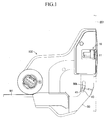
FIG. 1 is a side view of a vehicle door lock device according to an embodiment of the present invention as seen from an inner side of a vehicle. -
FIG. 2 is a side view for illustrating a relationship among main components of the vehicle door lock device illustrated inFIG. 1 . -
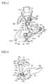
FIG. 3 is a view for illustrating a relationship among an inside open lever, an active lever, and a child safety lock mechanism at the time when the active lever illustrated inFIG. 2 is situated at an unlocked position and the child safety lock mechanism is held in an unset state. -
FIG. 4 is a view for illustrating a relationship in a vehicle width direction among an outside open lever, a spring, an open link, the active lever, a lift lever, and an unlocked state maintaining guide provided to a cover of a housing in the state illustrated inFIG. 3 . -
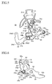
FIG. 5 is an explanatory view for illustrating an actuation at the time when the inside open lever illustrated inFIG. 3 is actuated in a door opening direction. -
FIG. 6 is a view for illustrating a relationship in the vehicle width direction among the outside open lever, the spring, the open link, the active lever, the lift lever, and the unlocked state maintaining guide provided to the cover of the housing in the state illustrated inFIG. 5 . Specifically,FIG. 6 is an explanatory view for illustrating an actuation in the state where the outside open lever is actuated in the door opening direction with the configuration illustrated inFIG. 4 . -
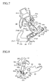
FIG. 7 is a view for illustrating a relationship among the inside open lever, the active lever, and the child safety lock mechanism at the time when the active lever illustrated inFIG. 2 is situated at a locked position and the child safety lock mechanism is held in the unset state. -
FIG. 8 is a view for illustrating a relationship in the vehicle width direction among the outside open lever, the spring, the open link, the active lever, the lift lever, and a locked state maintaining guide provided to the active lever in the state illustrated inFIG. 7 . -
FIG. 9 is an explanatory view for illustrating an actuation at the time when the inside open lever illustrated inFIG. 7 is actuated in the door opening direction. -
FIG. 10 is a view for illustrating a relationship in the vehicle width direction among the outside open lever, the spring, the open link, the active lever, the lift lever, and the locked state maintaining guide provided to the active lever in the state illustrated inFIG. 9 . Specifically,FIG. 10 is an explanatory view for illustrating an actuation in the state where the outside open lever is actuated in the door opening direction with the configuration illustrated inFIG. 8 . -
FIGS. 11 are explanatory views of actuation, for illustrating steps (procedures) of moving the active lever, which is situated at the unlocked position, to the locked position through use of an inside door handle and a child safety protector lever of the child safety lock mechanism. -
FIG. 12 is a right side view of a vehicle including the vehicle door lock device illustrated inFIGS. 1 to 11 . -
FIG. 13 is a side view corresponding toFIG. 3 (unset state), for illustrating another child safety lock mechanism, which is employable in place of the child safety lock mechanism illustrated inFIG. 3 and other figures. -
FIG. 14 is an explanatory view for illustrating an actuation at the time when an inside open lever illustrated inFIG. 13 is actuated in the door opening direction. -
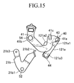
FIG. 15 is an explanatory view for illustrating an actuation at the time when a child safety protector lever illustrated inFIG. 14 is moved to a set position. -
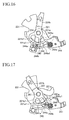
FIG. 16 is a side view corresponding toFIG. 3 (unlocked and unset state), for illustrating an inside open lever, an active lever, and a child safety lock mechanism according to another embodiment of the present invention, which are employable in place of the inside open lever, the active lever, and the child safety lock mechanism illustrated inFIG. 3 . -
FIG. 17 is an explanatory view for illustrating an actuation at the time when the inside open lever illustrated inFIG. 16 is actuated in the door opening direction. -
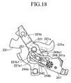
FIG. 18 is an explanatory view for illustrating an actuation at the time when a child safety protector lever illustrated inFIG. 17 is moved to the set position and the active lever is moved to the locked position. - In the following, an embodiment of the present invention is described with reference to the drawings.
FIGS. 1 to 12 illustrate a vehicle door lock device according to the embodiment of the present invention. A vehicledoor lock device 100 of this embodiment is mounted to adoor 201 which is installed on a rear right side of a vehicle (seeFIG. 12 ). As illustrated inFIGS. 1 and2 , the vehicledoor lock device 100 includes alatch mechanism 10, an insideopen lever 21, and an outsideopen lever 22, and further includes anopen link 23, alock operation unit 30, and a childsafety lock mechanism 40. Note that, the insideopen lever 21, the outsideopen lever 22, theopen link 23, thelock operation unit 30, the childsafety lock mechanism 40, and other components are assembled to a housing 50 (as a base member for assembling the components into the door) which is assembled to thedoor 201 together with thelatch mechanism 10. - As is well known, the
latch mechanism 10 is configured to maintain thedoor 201 in a closed state relative to abody 202, and is assembled to thehousing 50, that is, assembled to thedoor 201 together with thehousing 50. Thelatch mechanism 10 includes alatch 11 engageable with and disengageable from astriker 203 which is fixed to the body 202 (seeFIGS. 1 and12 ), a pawl (not shown) which is engageable with and disengageable from thelatch 11 and is capable of maintaining and releasing the engagement of thelatch 11 with thestriker 203, and a lift lever 12 (seeFIG. 4 ) provided integrally with the pawl (not shown). - As illustrated in
FIG. 4 , thelift lever 12 is assembled integrally to arotation shaft 13 of the pawl (not shown) through afitting hole 12a thereof, and rotates integrally with the pawl (not shown). Thelift lever 12 includes anengagement arm portion 12b engageable with and disengageable from alink head portion 23a of theopen link 23, and a main portion of the lift lever 12 (portion of thelift lever 12 which is fitted to the rotation shaft 13) rotates in a plane substantially parallel to the drawing sheet ofFIG. 4 . - In the above-mentioned
latch mechanism 10, when thelatch 11 engages with thestriker 203 and their engagement is maintained, thedoor 201 is maintained in a closed state (latched state). Further, in thelatch mechanism 10, when thelatch 11 disengages and separates from thestriker 203, thedoor 201 shifts from the closed state to an opened state (unlatched state). - The inside
open lever 21 is drivable along with an operation of aninside door handle 204 which is provided on an inner side of thedoor 201. The insideopen lever 21 is assembled rotatably to thehousing 50, and includes afirst lever 21 a which is linked to thelatch mechanism 10, and asecond lever 21 b which is assembled rotatably to thehousing 50 and is operated in association with theinside door handle 204. - In the inside
open lever 21, when the childsafety lock mechanism 40 is held in an unset state (seeFIGS. 11 (a) and 11 (b) ), the rotation of thesecond lever 21 b is transferable to thefirst lever 21 a so that pushing force transfer from the insideopen lever 21 to theopen link 23 is enabled. When the childsafety lock mechanism 40 is held in a set state (seeFIG. 11 (d) ), the rotation of thesecond lever 21 b is non-transferable to thefirst lever 21 a so that the pushing force transfer from the insideopen lever 21 to theopen link 23 is disabled. - As illustrated in
FIGS. 11 (c) and 11 (d) , thefirst lever 21 a is assembled rotatably to thehousing 50 through an intermediation of asupport shaft 51 at one end portion 21a1. As illustrated inFIGS. 3 and 4 , thefirst lever 21 a includes, at a middle portion thereof, a pushing portion 21a2 engageable with aninside engagement portion 22d of the outsideopen lever 22, and further includes alinear engagement groove 21 a3 at another end portion (rotation distal end portion) thereof. Thefirst lever 21a is linked to thelift lever 12 of thelatch mechanism 10 through an intermediation of the outsideopen lever 22 and the open link 23 (seeFIG. 4 ) at the pushingportion 21 a2, and when thelock operation unit 30 is held in an unlocked state ofFIG. 2 , thefirst lever 21 a is rotationally driven from an initial position ofFIG. 3 to an actuation position ofFIG. 5 so that thefirst lever 21 a can push theopen link 23 from an initial position ofFIG. 4 toward thelift lever 12. - As illustrated in
FIGS. 2 and3 , thesecond lever 21 b is assembled rotatably to thehousing 50 through an intermediation of asupport shaft 52 at abase end portion 21 b1. Thesecond lever 21 b includes, at one end portion thereof, anengagement portion 21 b2 engageable with arectangular bush 44a of anintermediate member 44 of the childsafety lock mechanism 40, and further includes, at another end portion thereof, anoperation arm portion 21 b3 coupled through an intermediation of a coupling member (see an operation cable W1 ofFIG. 1 ) to theinside door handle 204 which is provided on an inner side of thedoor 201. When theinside door handle 204 is operated to open the door, thesecond lever 21 b is rotationally driven from an initial position ofFIGS. 2 and3 to an actuation position ofFIG. 5 . - The outside
open lever 22 is rotationally drivable from an initial position (return position ofFIGS. 4 and8 ) to an actuation position (position ofFIGS. 6 and10 ) along with a door opening operation of anoutside door handle 205 which is provided on an outer side of thedoor 201, and is assembled rotatably to thehousing 50 through an intermediation of a support shaft 53 (arranged substantially orthogonal to the above-mentionedsupport shafts 51 and 52) at asupport hole 22a. The outsideopen lever 22 includes anoperation portion 22b linked to theoutside door handle 205 through an intermediation of an operation force transferring member (not shown) such as a link, a coupling hole portion (coupling portion) 22c coupled to theopen link 23, and theengagement arm portion 22d engageable with and disengageable from the pushing portion 21a2 of thefirst lever 21 a of the insideopen lever 21. - The
open link 23 includes the above-mentionedlink head portion 23a and further includes acoupling leg portion 23c and asupport portion 23d (seeFIG. 4 ). Theopen link 23 is assembled to the coupling hole portion (coupling portion) 22c of the outsideopen lever 22 at thecoupling leg portion 23c so as to be tiltable by a predetermined amount in a lateral direction ofFIG. 4 , and supports aspring 24 at thesupport portion 23d. A main portion of theopen link 23 is tilted in a plane substantially parallel to the drawing sheet ofFIG. 4 , and this plane is arranged in parallel to the plane in which the main portion of thelift lever 12 rotates. Further, theopen link 23 includes anengagement leg portion 23e engageable with and disengageable from apush arm portion 31 b of anactive lever 31 of thelock operation unit 30, anengagement arm portion 23f engageable with and disengageable from an unlockedstate maintaining guide 50a, and anengagement body portion 23g engageable with and disengageable from a lockedstate maintaining guide 31 a (seeFIGS. 8 and10 ). - When the
first lever 21 a of the insideopen lever 21 is rotationally driven from the initial position to the actuation position or when the outsideopen lever 22 is rotationally driven from the initial position to the actuation position, theopen link 23 is pushed from the initial position ofFIG. 4 or8 toward thelift lever 12, and is moved to an actuation position ofFIG. 6 or10 . Further, when theactive lever 31 moves from a locked position (position ofFIGS. 7 and9 ) to an unlocked position (position ofFIGS. 2 and3 ), theopen link 23 is switchable to an unlocked state (state ofFIG. 4 ), and when theactive lever 31 moves from the unlocked position to the locked position, theopen link 23 is switchable to a locked state (state ofFIG. 8 ). - Note that, when the
open link 23 is held in the unlocked state, as illustrated inFIGS. 4 and6 , door opening actuations of theopen levers lift lever 12 via theopen link 23, respectively. On the other hand, when theopen link 23 is held in the locked state, as illustrated inFIGS. 8 and10 , the door opening actuations of theopen levers open link 23, but are not transferred from theopen link 23 to thelift lever 12. - The
spring 24 is interposed between the outsideopen lever 22 and theopen link 23, and biases theopen link 23 relative to the outsideopen lever 22 so that theopen link 23 is brought into the unlocked state (state ofFIG. 4 ). Further, thespring 24 includes acoil portion 24a assembled to thesupport portion 23d of theopen link 23, and a pair ofarm portions coil portion 24a. Thearm portion 24b on one side engages with the outsideopen lever 22, and thearm portion 24c on the other side engages with theopen link 23. - Therefore, in a panic state where each of the door handles 204 and 205 and a remote control device (not shown) for actuating an
electric motor 32 of thelock operation unit 30 are operated at the same time in a door-locked state (locked state of the door 201), due to the function of thespring 24, theopen link 23 is biased so as to be brought into the unlocked state, and is linked to theengagement arm portion 12b of thelift lever 12 so as to be elastically and relatively movable. In addition, theopen link 23 is reliably returned to the initial position ofFIG. 4 . - The
lock operation unit 30 is configured to switch theopen link 23 to an unlocked position or a locked position. Thelock operation unit 30 includes theactive lever 31 which is rotationally drivable and is switchable between the unlocked position and the locked position, and further includes theelectric motor 32, aworm 33, aworm wheel 34, and the like (electric actuator) for rotationally driving theactive lever 31 to the locked position or the unlocked position. Through a lock operation of the remote control device (not shown) for actuating theelectric motor 32, theactive lever 31 is switched from the unlocked position ofFIGS. 2 and3 to the locked position ofFIG. 7 to bring theopen link 23 into the locked state. Further, through an unlock operation of the remote control device (not shown) for actuating theelectric motor 32, theactive lever 31 is switched from the locked position to the unlocked position to bring theopen link 23 into the unlocked state. Theactive lever 31 is assembled rotatably to thehousing 50 through an intermediation of asupport shaft 54 at asupport hole 31 c provided in a boss portion. - The
active lever 31 includes the above-mentioned lockedstate maintaining guide 31a, pusharm portion 31b, andsupport hole 31c, and further includes adrive portion 31 d linked to a pair ofcams worm wheel 34. Note that, theactive lever 31 is retainable at the unlocked position or the locked position by a positioning spring (not shown) which is assembled into thehousing 50 and is engageable with an engagement pin portion (not shown) provided on theactive lever 31. - The
electric motor 32 is a publicly known motor to be driven in accordance with the lock operation and the unlock operation of the remote control device or the like. Theworm 33 is provided integrally to anoutput shaft 32a of theelectric motor 32, and is rotationally driven by theelectric motor 32. Theworm wheel 34 is rotationally drivable by theworm 33, and is assembled rotatably to thehousing 50 through an intermediation of asupport shaft 55. Theworm wheel 34 includes the pair ofcams drive portion 31d of the active lever 31 (indicated by the broken lines inFIGS. 2 ,3 , and the like, though detailed description thereof is omitted herein). - In the above-mentioned
lock operation unit 30, when theactive lever 31 is situated at the unlocked position ofFIGS. 2 and3 and the remote control device (not shown) for actuating theelectric motor 32 is operated to lock the door, theelectric motor 32 rotationally drives theworm wheel 34 via theworm 33 in a counterclockwise direction by 180 degrees so that theactive lever 31 moves to the locked position ofFIG. 7 . When theactive lever 31 is situated at the locked position ofFIG. 7 and the remote control device (not shown) for actuating theelectric motor 32 is operated to unlock the door, theelectric motor 32 rotationally drives theworm wheel 34 via theworm 33 in a clockwise direction by 180 degrees so that theactive lever 31 moves to the unlocked position ofFIGS. 2 and3 . - The child
safety lock mechanism 40 is built into the insideopen lever 21, and is configured to enable the pushing force transfer from the insideopen lever 21 to the outsideopen lever 22 and theopen link 23 in the unset state (state of, for example,FIGS. 11(a) and 11(b) ), and to disable the pushing force transfer in the set state (state of, for example,FIG. 11(d) ). The childsafety lock mechanism 40 includes a childsafety protector lever 41 and further includes acoupling link 42, asupport pin 43, and theintermediate member 44. - The
intermediate member 44 includes therectangular bush 44a and acoupling shaft 44b, and is assembled to thefirst lever 21 a but is not assembled to thesecond lever 21 b. Further, theintermediate member 44 is coupled to oneend portion 41 a of the childsafety protector lever 41 through an intermediation of thecoupling link 42 and thesupport pin 43. Thecoupling link 42 is rotatable about thesupport pin 43, and hence theintermediate member 44 is rotatable relative to thehousing 50. Thecoupling shaft 44b is coupled integrally to therectangular bush 44a at one end thereof, and is coupled integrally to thecoupling link 42 at the other end thereof. Further, on an outer periphery (circular part) of a middle portion of thecoupling shaft 44b, thecoupling shaft 44b is assembled slidably to thelinear engagement groove 21 a3 which is provided to thefirst lever 21 a. - When the child
safety protector lever 41 is retained at an unset position of, for example,FIG. 11 (a) , theintermediate member 44 is retainable at an unset position ofFIG. 11 (a) . When the childsafety protector lever 41 is retained at a set position of, for example,FIG. 11 (d) , theintermediate member 44 is retainable at a set position ofFIG. 11 (d) . Thus, theintermediate member 44 is movable to the unset position or the set position by the childsafety protector lever 41. - The child
safety protector lever 41 is assembled rotatably to thehousing 50 through an intermediation of thesupport shaft 54 at amiddle portion 41b, and is retainable at the unset position ofFIGS. 11 (a) and 11 (b) or the set position ofFIGS. 11 (c) and 11 (d) . Further, the childsafety protector lever 41 includes anoperation portion 41 c provided in the vicinity of the oneend portion 41 a so as to project outside thehousing 50 through an arc-like insertion hole 50b of the housing 50 (seeFIG. 1 ). Only under the opened state of thedoor 201, the childsafety protector lever 41 is manually operable by theoperation portion 41 c from a vehicle interior side of thedoor 201. - The
coupling link 42 is coupled to thecoupling shaft 44b of theintermediate member 44 at one end portion (rotation distal end portion) thereof, and is coupled rotatably to the oneend portion 41 a of the childsafety protector lever 41 through an intermediation of thesupport pin 43 at the other end portion (rotation center portion) thereof. Thesupport pin 43 is assembled non-rotatably to the oneend portion 41 a of the childsafety protector lever 41, and rotatably supports thecoupling link 42. Further, aprotrusion 43a is provided integrally to thesupport pin 43, and aprotrusion 42a provided to thecoupling link 42 engages with theprotrusion 43a so as to restrict rotation of thecoupling link 42 relative to thesupport pin 43 in a counterclockwise direction ofFIG. 3 . - In this embodiment, when the
active lever 31 is situated at the unlocked position and the outsideopen lever 22 rotates between the initial position and the actuation position as illustrated inFIGS. 2 ,4 , and6 , the unlockedstate maintaining guide 50a provided on thehousing 50 maintains theopen link 23, which is separated from thepush arm portion 31 b of theactive lever 31, in the unlocked state. When the unlockedstate maintaining guide 50a maintains theopen link 23 in the unlocked state, as illustrated inFIG. 6 , theengagement arm portion 23f of theopen link 23 engages slidably with the unlockedstate maintaining guide 50a. Note that, a guide surface of the unlockedstate maintaining guide 50a (surface with which theengagement arm portion 23f slidably engages) is desired to be shaped in consideration of a movement locus of an engagement portion between theengagement arm portion 12b of thelift lever 12 and thelink head portion 23a of theopen link 23 so that a slip does not occur in the above-mentioned engagement portion. - On the other hand, when the
active lever 31 is situated at the locked position and the outsideopen lever 22 rotates between the initial position and the actuation position as illustrated inFIGS. 7 to 10 , the lockedstate maintaining guide 31 a provided on theactive lever 31 maintains theopen link 23, which is separated from thepush arm portion 31 b of theactive lever 31, in the locked state. When the lockedstate maintaining guide 31a maintains theopen link 23 in the locked state, as illustrated inFIG. 10 , theengagement body portion 23g of theopen link 23 engages slidably with the lockedstate maintaining guide 31 a. - By the way, in the above-mentioned vehicle
door lock device 100, anengagement leg portion 31 e is set on theactive lever 31, and a pushing portion (therectangular bush 44a serves also as this pushing portion) engageable with theengagement leg portion 31e is set on theintermediate member 44. When theintermediate member 44 is situated at the unset position, theinside door handle 204 is operated to open the door, and the childsafety protector lever 41 moves theintermediate member 44 to the set position, therectangular bush 44a (pushing portion) of theintermediate member 44 is set to engage with theengagement leg portion 31 e of theactive lever 31 so that theactive lever 31 is movable from the unlocked position to the locked position (seeFIGS. 11 ). - In the vehicle
door lock device 100 of this embodiment configured as described above, under a state in which theactive lever 31 is situated at the unlocked position and the childsafety protector lever 41 is situated at the unset position as illustrated inFIG. 3 (unlocked and unset state), when theinside door handle 204 or theoutside door handle 205 is operated to open the door, the insideopen lever 21 or the outsideopen lever 22 is actuated to open the door, and as illustrated inFIG. 4 , theopen link 23 held in the unlocked state is moved by the outsideopen lever 22 from the initial position (position ofFIG. 4 ) to the actuation position ofFIG. 6 so that thelift lever 12 rotates in an unlatching direction (in a clockwise direction ofFIGS. 4 and6 ). Therefore, the door opening actuation of the insideopen lever 21 or the door opening actuation of the outsideopen lever 22 is transferred to thelift lever 12 via theopen link 23 so that thelift lever 12 rotates in the unlatching direction. As a result, thelatch mechanism 10 is switched from the latched state to the unlatched state, and thus the door can be opened. - On the other hand, under a state in which the
active lever 31 is situated at the locked position and the childsafety protector lever 41 is situated at the unset position as illustrated inFIG. 7 (locked and unset state), when theinside door handle 204 or theoutside door handle 205 is operated to open the door, the insideopen lever 21 or the outsideopen lever 22 is actuated to open the door, and as illustrated inFIG. 8 , theopen link 23 held in the locked state is moved by the outsideopen lever 22 from the initial position (position ofFIG. 8 ) to the actuation position ofFIG. 10 . At this time, theopen link 23 held in the locked state ofFIGS. 8 and10 is lifted while being guided by the lockedstate maintaining guide 31a provided on theactive lever 31, and hence does not engage with thelift lever 12. Therefore, the door opening actuation of the outsideopen lever 22 is not transferred to thelift lever 12 so that thelift lever 12 does not rotate. As a result, thelatch mechanism 10 is maintained in the latched state, and thus the door cannot be opened. - Further, in the vehicle
door lock device 100 of this embodiment, under a state in which theactive lever 31 is situated at the unlocked position and the childsafety protector lever 41 is situated at the set position (unlocked and set state), when theinside door handle 204 is operated to open the door, thefirst lever 21 a of the insideopen lever 21 idly rotates relative to theintermediate member 44. Therefore, at this time, the outsideopen lever 22 is not actuated to open the door, and thus thedoor 201 cannot be opened. Note that, under the above-mentioned unlocked and set state, when theoutside door handle 205 is operated to open the door, the outsideopen lever 22 is actuated to open the door, and thus thedoor 201 can be opened. - Further, in the vehicle
door lock device 100 of this embodiment, under the above-mentioned unlocked and unset state (state ofFIG. 11(a) ) and under the opened state of thedoor 201, when theinside door handle 204 is operated to open the door, thefirst lever 21 a and thesecond lever 21 b of the insideopen lever 21 rotate as illustrated inFIG. 11 (b) . Therefore, under this state, when the childsafety protector lever 41 is operated from the unset position to the set position, therectangular bush 44a (pushing portion) of theintermediate member 44 engages with theengagement leg portion 31 e of theactive lever 31 to push theengagement leg portion 31 e. Accordingly, as illustrated inFIG. 11 (c) , theactive lever 31 moves from the unlocked position to the locked position. - Therefore, in a case of emergency (for example, in a case where the
electric motor 32 is not actuated), under the opened state of thedoor 201, a manual operation of operating theinside door handle 204 to open the door and a manual operation of operating the childsafety protector lever 41 from the unset position to the set position are sequentially performed so that theactive lever 31 situated at the unlocked position can be moved to the locked position. Thus, when theinside door handle 204 is then returned to the return position and thedoor 201 is closed, a locked and set state ofFIG. 11 (d) is obtained, and the locked state of the door 201 (door-locked state in which thedoor 201 cannot be opened even when theinside door handle 204 or theoutside door handle 205 is operated to open the door) is obtained. Note that, the above-mentioned locked state ofdoor 201 can be released when theelectric motor 32 is repaired to be actuated and then theelectric motor 32 is actuated to unlock the door. - By the way, in the vehicle
door lock device 100 of this embodiment, theinside door handle 204 and the childsafety protector lever 41 of the childsafety lock mechanism 40 are utilized to move theactive lever 31, which is situated at the unlocked position, to the locked position. In the vehicle door lock device including the childsafety lock mechanism 40, theinside door handle 204 and the childsafety protector lever 41 as existing components are used. Therefore, the emergency operation member to be used only when dealing with the emergency is unnecessary, and hence various problems which may be caused by employing the emergency operation member do not arise. - In the above-mentioned embodiment (embodiment illustrated in
FIGS. 1 to 12 ), the present invention is carried out in the following manner. That is, thefirst lever 21 a of the insideopen lever 21 is assembled rotatably to thehousing 50, and theintermediate member 44 is assembled to the rotation distal end portion (engagement groove 21 a3) of thefirst lever 21 a so as to be movable linearly, and is coupled to the rotation distal end portion (41 a) of the childsafety protector lever 41 through an intermediation of thecoupling link 42 and thesupport pin 43. Alternatively, as in another embodiment illustrated inFIGS. 13 to 15 , the present invention may be carried out in such a manner that afirst lever 121 a is assembled rotatably to the rotation distal end portion (41 a) of the childsafety protector lever 41 through an intermediation of thesupport pin 43, and theintermediate member 44 is assembled integrally to a rotation distal end portion 121a3 of thefirst lever 121 a. Note that, thefirst lever 121 a includes a pushing portion 121a2 corresponding to the pushing portion 21a2 of the above-mentioned embodiment, and further includes a protrusion (corresponding to theprotrusion 42a of the above-mentioned embodiment) engageable with and disengageable from the protrusion (43a) of thesupport pin 43. - In the embodiment illustrated in
FIGS. 13 to 15 , it is unnecessary to employ the components corresponding to thecoupling link 42 and thesupport shaft 51 which are employed in the embodiment illustrated inFIGS. 1 to 12 . Accordingly, the number of components of the childsafety lock mechanism 40 can be reduced, and thefirst lever 121 a does not need to include the engagement groove (21 a3), with the result that the childsafety lock mechanism 40 can be constructed simply at low cost. - Further, in the above-mentioned embodiment (embodiment illustrated in
FIGS. 1 to 12 ), the present invention is carried out in the following manner. That is, thefirst lever 21 a and thesecond lever 21 b of the insideopen lever 21 are assembled rotatably to thehousing 50 through an intermediation of thedifferent support shafts FIGS. 16 to 18 , the present invention may be carried out in such a manner that afirst lever 221 a and asecond lever 221 b of an insideopen lever 221 are arranged coaxially with each other, and are assembled rotatably to the housing through an intermediation of asingle support shaft 251. - In the embodiment illustrated in
FIGS. 16 to 18 , the present invention is applied to a configuration as disclosed in, for example,JP 2006-233456 A safety lock mechanism 240 built into the insideopen lever 221 includes a childsafety protector lever 241 and further includes anintermediate member 244. Theintermediate member 244 is an engagement member including aslide bush 244a which is assembled to a support portion 221a1 of thefirst lever 221 a so as to be movable along a radial direction of thesupport shaft 251, and anengagement pin 244b which projects from theslide bush 244a toward thesecond lever 221 b and passes through and engages with an odd-shapeelongated hole 221 b1 formed in thesecond lever 221 b and an arcelongated hole 241 a formed in the childsafety protector lever 241. - By the way, in the embodiment illustrated in
FIGS. 16 to 18 , anengagement leg portion 231 e is set on anactive lever 231 having a lock/unlock function equivalent to that of theactive lever 31 of the above-mentioned embodiment (embodiment illustrated inFIGS. 1 to 12 ), and a pushing portion 244a1 engageable with theengagement leg portion 231 e is set on theslide bush 244a of theintermediate member 244. When theintermediate member 244 is situated at the unset position (position ofFIGS. 16 and 17 ), the inside door handle (204) is operated to open the door, and the childsafety protector lever 241 moves theintermediate member 244 to the set position (position ofFIG. 18 ), the pushing portion 244a1 of theintermediate member 244 is set to engage with theengagement leg portion 231 e of theactive lever 231 so that theactive lever 231 is movable from the unlocked position (position ofFIGS. 16 and 17 ) to the locked position (position ofFIG. 18 ). - Therefore, also in the embodiment illustrated in
FIGS. 16 to 18 , in a case of emergency (for example, in a case where the electric motor is not actuated), under the opened state of the door (201), a manual operation of operating the inside door handle (204) to open the door and a manual operation of operating the childsafety protector lever 241 from the unset position (position ofFIGS. 16 and 17 ) to the set position (position ofFIG. 18 ) are sequentially performed so that theactive lever 231 situated at the unlocked position can be moved to the locked position. Thus, when the inside door handle (204) is then returned to the return position and the door (201) is closed, the locked and set state is obtained in the door lock device, and the locked state of the door (201) (door-locked state in which the door cannot be opened even when the inside door handle or the outside door handle is operated to open the door) is obtained. - In the embodiment illustrated in
FIGS. 1 to 12 and the embodiment illustrated inFIGS. 13 to 15 of the above-mentioned embodiments, the following configuration is employed. That is, theintermediate member 44 includes the pushing portion (rectangular bush 44a of the embodiment illustrated inFIGS. 1 to 12 ) engageable with theengagement leg portion 31 e of theactive lever 31, and is assembled to thefirst lever first lever second lever 21 b includes theengagement portion 21 b2 engageable with the pushing portion (rectangular bush 44a) of theintermediate member 44 held in the unset position. Therefore, under the unset state, theengagement portion 21 b2 of thesecond lever 21 b and the pushing portion of theintermediate member 44 engage with each other so that the pushing force transfer from the insideopen lever 21 to theopen link 23 is enabled. Note that, the pushing force transfer from the insideopen lever 21 to theopen link 23 under the unset state is performed in such a manner that the pushing force is transferred from theengagement portion 21 b2 of thesecond lever 21 b of the insideopen lever 21 to thefirst lever open lever 21 via the pushing portion of theintermediate member 44, and the pushing force is further transferred from the pushingportion 21 a2 or 121 a2 of thefirst lever open link 23 via the outsideopen lever 22. - In contrast, in the embodiment illustrated in
FIGS. 16 to 18 , the following configuration is employed. That is, theintermediate member 244 includes the pushing portion 244a1 engageable with theengagement leg portion 231e of theactive lever 231, and further includes theengagement pin 244b which passes through and engages with the odd-shapeelongated hole 221 b1 of thesecond lever 221 b and the arc elongatedhole 241 a of the childsafety protector lever 241. Therefore, under the unset state, thefirst lever 221 a and thesecond lever 221 b of the inside open lever 121 are integrated through an intermediation of theengagement pin 244b so that the pushing force transfer from the inside open lever 121 to the open link (23) is enabled. Thus, in the above-mentioned embodiment illustrated inFIGS. 1 to 12 and the above-mentioned embodiment illustrated inFIGS. 13 to 15 , it is unnecessary to employ the component corresponding to theengagement pin 244b of theintermediate member 244 of the above-mentioned embodiment illustrated inFIGS. 16 to 18 . Accordingly, the intermediate member (44) can be constructed more simply as compared to the above-mentioned embodiment illustrated inFIGS. 16 to 18 .
Claims (4)
- A vehicle door lock device (100), comprising:a latch mechanism (10) capable of maintaining a door (201) of a vehicle in a closed state relative to a body (202), and adapted to be assembled to the door (201) together with a housing (50);an inside open lever (21, 221) assembled to the housing (50), and adapted to be rotationally driven from an initial position to an actuation position along with a door opening operation of an inside door handle (204) which is provided on an inner side of the door (201);an outside open lever (22) assembled to the housing, and adapted to be rotationally driven from an initial position to an actuation position along with a door opening operation of an outside door handle (205) which is provided on an outer side of the door (201);an open link (23) assembled tiltably to a coupling portion (22c) of the outside open lever (22), which is shifted along with rotation of the outside open lever (22), the open link (23) comprising a link portion engageable with an engagement arm portion (22d) of a lift lever (12) of the latch mechanism (10), the open link (23) being pushed from an initial position toward the lift lever (12) when the inside open lever (21, 221) or the outside open lever (22) is rotationally driven from the initial position to the actuation position;an active lever (31, 231) assembled to the housing (50), the active lever (31, 231) being switched to a locked position through a lock actuation of an electric actuator (32, 33, 34) to bring the open link (23) into a locked state of being unlinkable to the lift lever (12), and switched to an unlocked position through an unlock actuation of the electric actuator (32, 33, 34) to bring the open link (23) into an unlocked state of being linkable to the lift lever (12); anda child safety lock mechanism (40, 240) built into the inside open lever (21, 221), the child safety lock mechanism (40, 240) being configured to enable pushing force transfer from the inside open lever (21, 221) to the open link (23) in an unset state, and to disable the pushing force transfer in a set state,wherein the inside open lever (21, 221) having the child safety lock mechanism (40, 240) built thereto comprises:a first lever (21a, 221a) assembled to the housing (50), and linked to the latch mechanism (10);a second lever (21b, 221b) assembled to the housing (50), and operated in association with the inside door handle (204);an intermediate member (244) interposed between the first lever (21a, 221a) and the second lever (21b, 221b), the intermediate member (244) being retainable at an unset position or a set position; anda child safety protector lever (41, 241) assembled to the housing (50), the child safety protector lever (41, 241) allowing the intermediate member (244) to move to the unset position or the set position through a manual operation performed from the inner side of the door (201),wherein the active lever (31, 231) comprises an engagement portion (31e, 231e) set thereon, and the intermediate member (44, 244) comprises a pushing portion (44a,244a1) set thereon, andwherein, when the intermediate member (44, 244) is situated at the unset position, the inside door handle (204) is operated to open the door (201), and the child safety protector lever (41, 241) moves the intermediate member (44, 244) to the set position, the pushing portion (44a, 244a1) of the intermediate member (244) is set to engage with the engagement portion (31e, 231e) of the active lever (31, 231) so that the active lever (31, 231) is movable to the locked position.
- A vehicle door lock device (100) according to claim 1,
wherein the intermediate member (44) is assembled to the first lever (21a) so as to be rotatable integrally with the first lever (21a),
wherein the second lever (21b) comprises an engagement portion (21b2) engageable with the pushing portion (44a) of the intermediate member (44) held in the unset position, and
wherein, under the unset state, the engagement portion (21b2) of the second lever (21b) and the pushing portion (44a) of the intermediate member (44) engage with each other so that the pushing force transfer from the inside open lever (21) to the open link (23) is enabled. - A vehicle door lock device (100) according to claim 1 or 2, wherein the first lever (21 a) and the second lever (21 b) are assembled rotatably to the housing (50) through an intermediation of different support shafts (51; 52).
- A vehicle door lock device (100) according to claim 1 or 2, wherein the first lever (221a) and the second lever (221b) are arranged coaxially with each other, and are assembled rotatably to the housing (50) through an intermediation of a single support shaft (251)
Applications Claiming Priority (2)
| Application Number | Priority Date | Filing Date | Title |
|---|---|---|---|
| JP2010098722A JP5293674B2 (en) | 2010-04-22 | 2010-04-22 | Vehicle door lock device |
| PCT/JP2011/056379 WO2011132482A1 (en) | 2010-04-22 | 2011-03-17 | Vehicle door lock device |
Publications (3)
| Publication Number | Publication Date |
|---|---|
| EP2562337A1 EP2562337A1 (en) | 2013-02-27 |
| EP2562337A4 EP2562337A4 (en) | 2013-07-24 |
| EP2562337B1 true EP2562337B1 (en) | 2015-10-14 |
Family
ID=44834021
Family Applications (1)
| Application Number | Title | Priority Date | Filing Date |
|---|---|---|---|
| EP11771822.1A Not-in-force EP2562337B1 (en) | 2010-04-22 | 2011-03-17 | Vehicle door lock device |
Country Status (5)
| Country | Link |
|---|---|
| US (1) | US8740264B2 (en) |
| EP (1) | EP2562337B1 (en) |
| JP (1) | JP5293674B2 (en) |
| CN (1) | CN203145622U (en) |
| WO (1) | WO2011132482A1 (en) |
Families Citing this family (17)
| Publication number | Priority date | Publication date | Assignee | Title |
|---|---|---|---|---|
| US9382732B2 (en) * | 2011-01-21 | 2016-07-05 | GM Global Technology Operations LLC | Door assembly with anti-theft device |
| JP5437309B2 (en) * | 2011-04-22 | 2014-03-12 | アイシン精機株式会社 | Rotating lever position holding device and vehicular door lock device including the rotating lever position holding device |
| JP5729880B2 (en) * | 2012-01-20 | 2015-06-03 | アイシン機工株式会社 | Door lock device |
| US10060165B2 (en) * | 2012-07-31 | 2018-08-28 | Aisin Seiki Kabushiki Kaisha | Door lock device |
| KR20150092148A (en) * | 2012-12-12 | 2015-08-12 | 볼보 컨스트럭션 이큅먼트 에이비 | Door locking device and construction machine including same |
| DE102013006521A1 (en) * | 2013-04-16 | 2014-10-16 | Kiekert Aktiengesellschaft | Motor vehicle door lock |
| CN103527011A (en) * | 2013-11-08 | 2014-01-22 | 昆山麦格纳汽车系统有限公司 | Novel automobile door lock external releasing mechanism |
| US10190342B2 (en) * | 2014-09-05 | 2019-01-29 | HYUNDAI MOTOR INDIA ENGINEERING Pvt. Ltd. | Door lock mechanism for vehicle |
| US9334681B2 (en) | 2014-10-03 | 2016-05-10 | Continental Automotive Systems, Inc. | Automatic door child safety lock release in a crash event |
| JP6106145B2 (en) * | 2014-10-28 | 2017-03-29 | 本田技研工業株式会社 | Vehicle door |
| JP6450979B2 (en) * | 2015-04-28 | 2019-01-16 | 三井金属アクト株式会社 | Door lock device for automobile |
| CN105735780B (en) * | 2016-04-18 | 2018-08-24 | 烟台三环锁业集团股份有限公司 | A kind of children's lock construction of automobile side door lock |
| DE102017123622A1 (en) * | 2017-10-11 | 2019-04-11 | Kiekert Ag | Motor vehicle lock, in particular tailgate lock |
| JP6988412B2 (en) * | 2017-12-01 | 2022-01-05 | トヨタ自動車株式会社 | Sliding door device for vehicles |
| KR102518596B1 (en) * | 2018-01-30 | 2023-04-05 | 현대자동차 주식회사 | Power child lock operating device |
| EP3613928B1 (en) * | 2018-08-17 | 2021-06-09 | Inteva Products, LLC | Inside release spring for vehicle door |
| CN218581385U (en) | 2021-09-24 | 2023-03-07 | 极氪汽车(宁波杭州湾新区)有限公司 | Automobile inner buckle and automobile door applying same |
Family Cites Families (17)
| Publication number | Priority date | Publication date | Assignee | Title |
|---|---|---|---|---|
| JP3301700B2 (en) * | 1996-07-10 | 2002-07-15 | 三井金属鉱業株式会社 | Relay mechanism for sliding doors for vehicles |
| GB2332235B (en) * | 1997-12-12 | 2001-12-05 | Meritor Light Vehicle Sys Ltd | Vehicle door latch mechanism |
| FR2773836B1 (en) * | 1998-01-20 | 2000-03-24 | Kiekert Ag | MOTOR VEHICLE DOOR CLOSURE |
| IT1320389B1 (en) * | 2000-06-02 | 2003-11-26 | Atoma Roltra Spa | LOCK FOR A CAR DOOR. |
| JP3875472B2 (en) * | 2000-09-06 | 2007-01-31 | 株式会社大井製作所 | Child lock mechanism in door lock device |
| JP4588926B2 (en) * | 2001-06-21 | 2010-12-01 | アイシン精機株式会社 | Door lock device |
| DE10360982A1 (en) * | 2002-12-24 | 2004-10-07 | Aisin Seiki K.K., Kariya | Torque transmission element and door locking device |
| JP2004251106A (en) * | 2003-01-30 | 2004-09-09 | Aisin Seiki Co Ltd | Door lock device |
| JP2004244993A (en) * | 2003-02-17 | 2004-09-02 | Aisin Seiki Co Ltd | Door lock device |
| JP2004244994A (en) * | 2003-02-17 | 2004-09-02 | Aisin Seiki Co Ltd | Door lock device |
| JP4321404B2 (en) | 2004-08-19 | 2009-08-26 | アイシン精機株式会社 | Vehicle door lock device |
| EP1813746B1 (en) * | 2004-11-16 | 2014-04-09 | Aisin Seiki Kabushiki Kaisha | Door lock apparatus for vehicles |
| JP2006233456A (en) | 2005-02-22 | 2006-09-07 | Aisin Seiki Co Ltd | Door lock device |
| JP4503051B2 (en) * | 2007-07-23 | 2010-07-14 | 三井金属鉱業株式会社 | Door lock device |
| JP4918915B2 (en) | 2008-01-10 | 2012-04-18 | アイシン精機株式会社 | Vehicle door lock device |
| JP4618318B2 (en) * | 2008-04-18 | 2011-01-26 | アイシン精機株式会社 | Vehicle door lock device |
| JP5447860B2 (en) | 2010-03-24 | 2014-03-19 | アイシン精機株式会社 | Vehicle door lock device |
-
2010
- 2010-04-22 JP JP2010098722A patent/JP5293674B2/en not_active Expired - Fee Related
-
2011
- 2011-03-17 CN CN2011900004356U patent/CN203145622U/en not_active Expired - Fee Related
- 2011-03-17 WO PCT/JP2011/056379 patent/WO2011132482A1/en active Application Filing
- 2011-03-17 EP EP11771822.1A patent/EP2562337B1/en not_active Not-in-force
- 2011-03-17 US US13/642,409 patent/US8740264B2/en not_active Expired - Fee Related
Also Published As
| Publication number | Publication date |
|---|---|
| CN203145622U (en) | 2013-08-21 |
| US20130036779A1 (en) | 2013-02-14 |
| WO2011132482A1 (en) | 2011-10-27 |
| JP2011226193A (en) | 2011-11-10 |
| EP2562337A1 (en) | 2013-02-27 |
| EP2562337A4 (en) | 2013-07-24 |
| JP5293674B2 (en) | 2013-09-18 |
| US8740264B2 (en) | 2014-06-03 |
Similar Documents
| Publication | Publication Date | Title |
|---|---|---|
| EP2562337B1 (en) | Vehicle door lock device | |
| EP2578779B1 (en) | Vehicle door lock device | |
| US9376843B2 (en) | Position holding device for rotating lever and vehicle door lock device provided with said position holding device for rotating lever | |
| WO2011118356A1 (en) | Vehicle door lock device | |
| EP2458118B1 (en) | Door lock device for vehicle | |
| JP5279433B2 (en) | Door lock device | |
| EP2460960B1 (en) | Door lock device for vehicle | |
| WO2009087892A1 (en) | Door lock device for vehicle | |
| WO2006019191A1 (en) | Vehicle door lock device | |
| EP2369103A2 (en) | Double-locking door lock apparatus for vehicle | |
| US20090218830A1 (en) | Door lock device | |
| US9791885B2 (en) | Rotating-lever-position-holding device | |
| US6866310B2 (en) | Door latch operation device for vehicle | |
| JP5150526B2 (en) | Door latch device | |
| JP6596738B2 (en) | Door closing device | |
| JP7290098B2 (en) | Vehicle door lock device | |
| JP5375589B2 (en) | Vehicle door lock device | |
| JP2004244994A (en) | Door lock device |
Legal Events
| Date | Code | Title | Description |
|---|---|---|---|
| PUAI | Public reference made under article 153(3) epc to a published international application that has entered the european phase |
Free format text: ORIGINAL CODE: 0009012 |
|
| 17P | Request for examination filed |
Effective date: 20121029 |
|
| AK | Designated contracting states |
Kind code of ref document: A1 Designated state(s): AL AT BE BG CH CY CZ DE DK EE ES FI FR GB GR HR HU IE IS IT LI LT LU LV MC MK MT NL NO PL PT RO RS SE SI SK SM TR |
|
| A4 | Supplementary search report drawn up and despatched |
Effective date: 20130620 |
|
| RIC1 | Information provided on ipc code assigned before grant |
Ipc: E05B 65/20 20060101AFI20130614BHEP Ipc: B60J 5/00 20060101ALI20130614BHEP |
|
| DAX | Request for extension of the european patent (deleted) | ||
| REG | Reference to a national code |
Ref country code: DE Ref legal event code: R079 Ref document number: 602011020637 Country of ref document: DE Free format text: PREVIOUS MAIN CLASS: E05B0065200000 Ipc: E05B0077260000 |
|
| RIC1 | Information provided on ipc code assigned before grant |
Ipc: E05B 77/26 20140101AFI20150212BHEP Ipc: E05B 81/90 20140101ALI20150212BHEP |
|
| GRAP | Despatch of communication of intention to grant a patent |
Free format text: ORIGINAL CODE: EPIDOSNIGR1 |
|
| INTG | Intention to grant announced |
Effective date: 20150402 |
|
| GRAS | Grant fee paid |
Free format text: ORIGINAL CODE: EPIDOSNIGR3 |
|
| GRAA | (expected) grant |
Free format text: ORIGINAL CODE: 0009210 |
|
| AK | Designated contracting states |
Kind code of ref document: B1 Designated state(s): AL AT BE BG CH CY CZ DE DK EE ES FI FR GB GR HR HU IE IS IT LI LT LU LV MC MK MT NL NO PL PT RO RS SE SI SK SM TR |
|
| REG | Reference to a national code |
Ref country code: GB Ref legal event code: FG4D |
|
| REG | Reference to a national code |
Ref country code: AT Ref legal event code: REF Ref document number: 755223 Country of ref document: AT Kind code of ref document: T Effective date: 20151015 Ref country code: CH Ref legal event code: EP |
|
| REG | Reference to a national code |
Ref country code: IE Ref legal event code: FG4D |
|
| REG | Reference to a national code |
Ref country code: DE Ref legal event code: R096 Ref document number: 602011020637 Country of ref document: DE |
|
| REG | Reference to a national code |
Ref country code: FR Ref legal event code: PLFP Year of fee payment: 6 |
|
| REG | Reference to a national code |
Ref country code: NL Ref legal event code: MP Effective date: 20151014 |
|
| REG | Reference to a national code |
Ref country code: LT Ref legal event code: MG4D |
|
| REG | Reference to a national code |
Ref country code: AT Ref legal event code: MK05 Ref document number: 755223 Country of ref document: AT Kind code of ref document: T Effective date: 20151014 |
|
| PG25 | Lapsed in a contracting state [announced via postgrant information from national office to epo] |
Ref country code: IT Free format text: LAPSE BECAUSE OF FAILURE TO SUBMIT A TRANSLATION OF THE DESCRIPTION OR TO PAY THE FEE WITHIN THE PRESCRIBED TIME-LIMIT Effective date: 20151014 Ref country code: HR Free format text: LAPSE BECAUSE OF FAILURE TO SUBMIT A TRANSLATION OF THE DESCRIPTION OR TO PAY THE FEE WITHIN THE PRESCRIBED TIME-LIMIT Effective date: 20151014 Ref country code: LT Free format text: LAPSE BECAUSE OF FAILURE TO SUBMIT A TRANSLATION OF THE DESCRIPTION OR TO PAY THE FEE WITHIN THE PRESCRIBED TIME-LIMIT Effective date: 20151014 Ref country code: NO Free format text: LAPSE BECAUSE OF FAILURE TO SUBMIT A TRANSLATION OF THE DESCRIPTION OR TO PAY THE FEE WITHIN THE PRESCRIBED TIME-LIMIT Effective date: 20160114 Ref country code: ES Free format text: LAPSE BECAUSE OF FAILURE TO SUBMIT A TRANSLATION OF THE DESCRIPTION OR TO PAY THE FEE WITHIN THE PRESCRIBED TIME-LIMIT Effective date: 20151014 Ref country code: IS Free format text: LAPSE BECAUSE OF FAILURE TO SUBMIT A TRANSLATION OF THE DESCRIPTION OR TO PAY THE FEE WITHIN THE PRESCRIBED TIME-LIMIT Effective date: 20160214 Ref country code: NL Free format text: LAPSE BECAUSE OF FAILURE TO SUBMIT A TRANSLATION OF THE DESCRIPTION OR TO PAY THE FEE WITHIN THE PRESCRIBED TIME-LIMIT Effective date: 20151014 |
|
| PG25 | Lapsed in a contracting state [announced via postgrant information from national office to epo] |
Ref country code: GR Free format text: LAPSE BECAUSE OF FAILURE TO SUBMIT A TRANSLATION OF THE DESCRIPTION OR TO PAY THE FEE WITHIN THE PRESCRIBED TIME-LIMIT Effective date: 20160115 Ref country code: PT Free format text: LAPSE BECAUSE OF FAILURE TO SUBMIT A TRANSLATION OF THE DESCRIPTION OR TO PAY THE FEE WITHIN THE PRESCRIBED TIME-LIMIT Effective date: 20160215 Ref country code: PL Free format text: LAPSE BECAUSE OF FAILURE TO SUBMIT A TRANSLATION OF THE DESCRIPTION OR TO PAY THE FEE WITHIN THE PRESCRIBED TIME-LIMIT Effective date: 20151014 Ref country code: RS Free format text: LAPSE BECAUSE OF FAILURE TO SUBMIT A TRANSLATION OF THE DESCRIPTION OR TO PAY THE FEE WITHIN THE PRESCRIBED TIME-LIMIT Effective date: 20151014 Ref country code: AT Free format text: LAPSE BECAUSE OF FAILURE TO SUBMIT A TRANSLATION OF THE DESCRIPTION OR TO PAY THE FEE WITHIN THE PRESCRIBED TIME-LIMIT Effective date: 20151014 Ref country code: LV Free format text: LAPSE BECAUSE OF FAILURE TO SUBMIT A TRANSLATION OF THE DESCRIPTION OR TO PAY THE FEE WITHIN THE PRESCRIBED TIME-LIMIT Effective date: 20151014 Ref country code: SE Free format text: LAPSE BECAUSE OF FAILURE TO SUBMIT A TRANSLATION OF THE DESCRIPTION OR TO PAY THE FEE WITHIN THE PRESCRIBED TIME-LIMIT Effective date: 20151014 Ref country code: FI Free format text: LAPSE BECAUSE OF FAILURE TO SUBMIT A TRANSLATION OF THE DESCRIPTION OR TO PAY THE FEE WITHIN THE PRESCRIBED TIME-LIMIT Effective date: 20151014 |
|
| REG | Reference to a national code |
Ref country code: DE Ref legal event code: R097 Ref document number: 602011020637 Country of ref document: DE |
|
| PG25 | Lapsed in a contracting state [announced via postgrant information from national office to epo] |
Ref country code: CZ Free format text: LAPSE BECAUSE OF FAILURE TO SUBMIT A TRANSLATION OF THE DESCRIPTION OR TO PAY THE FEE WITHIN THE PRESCRIBED TIME-LIMIT Effective date: 20151014 |
|
| PLBE | No opposition filed within time limit |
Free format text: ORIGINAL CODE: 0009261 |
|
| STAA | Information on the status of an ep patent application or granted ep patent |
Free format text: STATUS: NO OPPOSITION FILED WITHIN TIME LIMIT |
|
| PG25 | Lapsed in a contracting state [announced via postgrant information from national office to epo] |
Ref country code: RO Free format text: LAPSE BECAUSE OF FAILURE TO SUBMIT A TRANSLATION OF THE DESCRIPTION OR TO PAY THE FEE WITHIN THE PRESCRIBED TIME-LIMIT Effective date: 20151014 Ref country code: BE Free format text: LAPSE BECAUSE OF NON-PAYMENT OF DUE FEES Effective date: 20160331 Ref country code: SM Free format text: LAPSE BECAUSE OF FAILURE TO SUBMIT A TRANSLATION OF THE DESCRIPTION OR TO PAY THE FEE WITHIN THE PRESCRIBED TIME-LIMIT Effective date: 20151014 Ref country code: EE Free format text: LAPSE BECAUSE OF FAILURE TO SUBMIT A TRANSLATION OF THE DESCRIPTION OR TO PAY THE FEE WITHIN THE PRESCRIBED TIME-LIMIT Effective date: 20151014 Ref country code: DK Free format text: LAPSE BECAUSE OF FAILURE TO SUBMIT A TRANSLATION OF THE DESCRIPTION OR TO PAY THE FEE WITHIN THE PRESCRIBED TIME-LIMIT Effective date: 20151014 Ref country code: SK Free format text: LAPSE BECAUSE OF FAILURE TO SUBMIT A TRANSLATION OF THE DESCRIPTION OR TO PAY THE FEE WITHIN THE PRESCRIBED TIME-LIMIT Effective date: 20151014 |
|
| 26N | No opposition filed |
Effective date: 20160715 |
|
| REG | Reference to a national code |
Ref country code: FR Ref legal event code: PLFP Year of fee payment: 7 |
|
| PG25 | Lapsed in a contracting state [announced via postgrant information from national office to epo] |
Ref country code: LU Free format text: LAPSE BECAUSE OF FAILURE TO SUBMIT A TRANSLATION OF THE DESCRIPTION OR TO PAY THE FEE WITHIN THE PRESCRIBED TIME-LIMIT Effective date: 20160317 Ref country code: MC Free format text: LAPSE BECAUSE OF FAILURE TO SUBMIT A TRANSLATION OF THE DESCRIPTION OR TO PAY THE FEE WITHIN THE PRESCRIBED TIME-LIMIT Effective date: 20151014 |
|
| REG | Reference to a national code |
Ref country code: CH Ref legal event code: PL |
|
| GBPC | Gb: european patent ceased through non-payment of renewal fee |
Effective date: 20160317 |
|
| PG25 | Lapsed in a contracting state [announced via postgrant information from national office to epo] |
Ref country code: SI Free format text: LAPSE BECAUSE OF FAILURE TO SUBMIT A TRANSLATION OF THE DESCRIPTION OR TO PAY THE FEE WITHIN THE PRESCRIBED TIME-LIMIT Effective date: 20151014 |
|
| REG | Reference to a national code |
Ref country code: IE Ref legal event code: MM4A |
|
| PG25 | Lapsed in a contracting state [announced via postgrant information from national office to epo] |
Ref country code: BE Free format text: LAPSE BECAUSE OF FAILURE TO SUBMIT A TRANSLATION OF THE DESCRIPTION OR TO PAY THE FEE WITHIN THE PRESCRIBED TIME-LIMIT Effective date: 20151014 |
|
| PG25 | Lapsed in a contracting state [announced via postgrant information from national office to epo] |
Ref country code: CH Free format text: LAPSE BECAUSE OF NON-PAYMENT OF DUE FEES Effective date: 20160331 Ref country code: GB Free format text: LAPSE BECAUSE OF NON-PAYMENT OF DUE FEES Effective date: 20160317 Ref country code: IE Free format text: LAPSE BECAUSE OF NON-PAYMENT OF DUE FEES Effective date: 20160317 Ref country code: LI Free format text: LAPSE BECAUSE OF NON-PAYMENT OF DUE FEES Effective date: 20160331 |
|
| PG25 | Lapsed in a contracting state [announced via postgrant information from national office to epo] |
Ref country code: MT Free format text: LAPSE BECAUSE OF FAILURE TO SUBMIT A TRANSLATION OF THE DESCRIPTION OR TO PAY THE FEE WITHIN THE PRESCRIBED TIME-LIMIT Effective date: 20151014 |
|
| REG | Reference to a national code |
Ref country code: FR Ref legal event code: PLFP Year of fee payment: 8 |
|
| PG25 | Lapsed in a contracting state [announced via postgrant information from national office to epo] |
Ref country code: HU Free format text: LAPSE BECAUSE OF FAILURE TO SUBMIT A TRANSLATION OF THE DESCRIPTION OR TO PAY THE FEE WITHIN THE PRESCRIBED TIME-LIMIT; INVALID AB INITIO Effective date: 20110317 Ref country code: CY Free format text: LAPSE BECAUSE OF FAILURE TO SUBMIT A TRANSLATION OF THE DESCRIPTION OR TO PAY THE FEE WITHIN THE PRESCRIBED TIME-LIMIT Effective date: 20151014 |
|
| PG25 | Lapsed in a contracting state [announced via postgrant information from national office to epo] |
Ref country code: MT Free format text: LAPSE BECAUSE OF FAILURE TO SUBMIT A TRANSLATION OF THE DESCRIPTION OR TO PAY THE FEE WITHIN THE PRESCRIBED TIME-LIMIT Effective date: 20160331 Ref country code: MK Free format text: LAPSE BECAUSE OF FAILURE TO SUBMIT A TRANSLATION OF THE DESCRIPTION OR TO PAY THE FEE WITHIN THE PRESCRIBED TIME-LIMIT Effective date: 20151014 Ref country code: TR Free format text: LAPSE BECAUSE OF FAILURE TO SUBMIT A TRANSLATION OF THE DESCRIPTION OR TO PAY THE FEE WITHIN THE PRESCRIBED TIME-LIMIT Effective date: 20151014 |
|
| PG25 | Lapsed in a contracting state [announced via postgrant information from national office to epo] |
Ref country code: BG Free format text: LAPSE BECAUSE OF FAILURE TO SUBMIT A TRANSLATION OF THE DESCRIPTION OR TO PAY THE FEE WITHIN THE PRESCRIBED TIME-LIMIT Effective date: 20151014 |
|
| PG25 | Lapsed in a contracting state [announced via postgrant information from national office to epo] |
Ref country code: AL Free format text: LAPSE BECAUSE OF FAILURE TO SUBMIT A TRANSLATION OF THE DESCRIPTION OR TO PAY THE FEE WITHIN THE PRESCRIBED TIME-LIMIT Effective date: 20151014 |
|
| PGFP | Annual fee paid to national office [announced via postgrant information from national office to epo] |
Ref country code: DE Payment date: 20200303 Year of fee payment: 10 |
|
| PGFP | Annual fee paid to national office [announced via postgrant information from national office to epo] |
Ref country code: FR Payment date: 20200214 Year of fee payment: 10 |
|
| REG | Reference to a national code |
Ref country code: DE Ref legal event code: R119 Ref document number: 602011020637 Country of ref document: DE |
|
| PG25 | Lapsed in a contracting state [announced via postgrant information from national office to epo] |
Ref country code: FR Free format text: LAPSE BECAUSE OF NON-PAYMENT OF DUE FEES Effective date: 20210331 Ref country code: DE Free format text: LAPSE BECAUSE OF NON-PAYMENT OF DUE FEES Effective date: 20211001 |