EP2562269B1 - A scraping roller - Google Patents
A scraping roller Download PDFInfo
- Publication number
- EP2562269B1 EP2562269B1 EP12181190.5A EP12181190A EP2562269B1 EP 2562269 B1 EP2562269 B1 EP 2562269B1 EP 12181190 A EP12181190 A EP 12181190A EP 2562269 B1 EP2562269 B1 EP 2562269B1
- Authority
- EP
- European Patent Office
- Prior art keywords
- scraping
- roller
- teeth
- tooth
- vertex
- Prior art date
- Legal status (The legal status is an assumption and is not a legal conclusion. Google has not performed a legal analysis and makes no representation as to the accuracy of the status listed.)
- Not-in-force
Links
- 238000007790 scraping Methods 0.000 title claims description 140
- 241001465754 Metazoa Species 0.000 claims description 8
- 241000772415 Neovison vison Species 0.000 claims description 5
- 239000000463 material Substances 0.000 description 3
- 230000002093 peripheral effect Effects 0.000 description 3
- 230000000694 effects Effects 0.000 description 2
- 229920002635 polyurethane Polymers 0.000 description 2
- 239000004814 polyurethane Substances 0.000 description 2
- 230000002730 additional effect Effects 0.000 description 1
- 229920001971 elastomer Polymers 0.000 description 1
- 230000001939 inductive effect Effects 0.000 description 1
- 229920003052 natural elastomer Polymers 0.000 description 1
- 229920001194 natural rubber Polymers 0.000 description 1
- 239000004033 plastic Substances 0.000 description 1
- 229920003023 plastic Polymers 0.000 description 1
- 239000012858 resilient material Substances 0.000 description 1
- 239000005060 rubber Substances 0.000 description 1
- 229920002379 silicone rubber Polymers 0.000 description 1
- 239000004945 silicone rubber Substances 0.000 description 1
- 229920003051 synthetic elastomer Polymers 0.000 description 1
- 239000005061 synthetic rubber Substances 0.000 description 1
Images


Classifications
-
- C—CHEMISTRY; METALLURGY
- C14—SKINS; HIDES; PELTS; LEATHER
- C14B—MECHANICAL TREATMENT OR PROCESSING OF SKINS, HIDES OR LEATHER IN GENERAL; PELT-SHEARING MACHINES; INTESTINE-SPLITTING MACHINES
- C14B17/00—Details of apparatus or machines for manufacturing or treating skins, hides, leather, or furs
- C14B17/02—Blading cylinders or other working cylinders, e.g. slicking or scraping cylinders
-
- C—CHEMISTRY; METALLURGY
- C14—SKINS; HIDES; PELTS; LEATHER
- C14B—MECHANICAL TREATMENT OR PROCESSING OF SKINS, HIDES OR LEATHER IN GENERAL; PELT-SHEARING MACHINES; INTESTINE-SPLITTING MACHINES
- C14B1/00—Manufacture of leather; Machines or devices therefor
- C14B1/02—Fleshing, unhairing, samming, stretching-out, setting-out, shaving, splitting, or skiving skins, hides, or leather
-
- C—CHEMISTRY; METALLURGY
- C14—SKINS; HIDES; PELTS; LEATHER
- C14B—MECHANICAL TREATMENT OR PROCESSING OF SKINS, HIDES OR LEATHER IN GENERAL; PELT-SHEARING MACHINES; INTESTINE-SPLITTING MACHINES
- C14B15/00—Mechanical treatment of furs
Definitions
- the invention relates to a scraping roller for scraping the skin side of an animal pelt.
- US 4,745,782 discloses an apparatus with a scraping roller for scraping the skin side of an animal pelt.
- the scraping roller comprises a plurality of peripherally spaced teeth having scraping edges defining a substantially circular cylindrical surface.
- Each of the scraping edges is substantially V-shaped and defines an obtuse angle and the scraping edges are substantially symmetrical with respect to the central symmetry plane of the scraping roller.
- DK 173 611 B1 discloses another apparatus with a scraping roller for scraping the skin side of an animal pelt.
- the scraping roller comprises scraping edges extending in the longitudinal direction of the scraping roller to rotate a tubular skin on a mandrel of the apparatus.
- Danish patent application No. DK 2010 70431 in the name of Pamutec discloses a further apparatus with a scraping roller comprising curved scraping edges for scraping the skin side of an animal pelt.
- the scraping edges are symmetrical with respect to the central symmetry plane of the scraping roller and are in principle of a V-shape.
- the scraping edges have a gap at the vertex, i.e. at the top of the V and the two parts of each scraping edge are in some embodiments formed to overlap at the vertex.
- Scraping rollers with scraping edges are known to cause parts of the apparatus on which the scraping roller is arranged to vibrate unintentionally during operation, especially if the roller or rollers on the apparatus causes the apparatus to vibrate with an eigenfrequency of the apparatus or a part of the apparatus. Such vibrations may influent negatively on the quality of the scraping, and/or may cause increased wear on parts of the apparatus.
- the present invention relates to a scraping roller for scraping the skin side of an animal pelt, according to claim 1.
- the axial position of the vertex is understood the position with respect to the axial direction of the roller and likewise, the axial distance is measured as the distance in the axial direction of the roller.
- the axial distance of a vertex from the first end of the scraping roller is the distance in the axial direction of the roller from the first end of the scraping roller and to the axial position of the vertex.
- the axial positions of the vertices of the scraping blades of a roller according to the present invention may comprise more than one maximum and one minimum, e.g. two of each with e.g. one or two intermediate teeth between each minimum and the consecutive maximum and between each maximum and the consecutive minimum, so that the roller comprises eight or twelve teeth, respectively.
- the axial positions of the vertices of the scraping blades of the roller comprise one maximum and one minimum only.
- the scraping edges are preferably continuous edges extending from one end of the scraping roller to the other, but the scraping edges may alternatively be provided with on or more openings along the extent thereof, such as at the vertex.
- the parts of the scraping edges on the two sides of the vertex are displaced from each other in the angular direction of the roller at the vertex and define an opening there between, and the parts of the scraping edges may even be overlapping at the vertex.
- vertex may be understood a sharp corner, in particular an obtuse angle between the parts of the scraping edge extending on each side of the vertex.
- the scraping edge is said to be of a V-shape.
- the vertex may be of a rounded shape, e.g. with a radius of curvature in the range of 15 to 40 millimetres, such as 20 to 30 millimetres, in which case the scraping edge is said to be of a U-shape.
- the scraping edges By arranging the scraping edges with different positions of the vertices as described above, it is possible to reduce or even avoid vibrations of the apparatus at an eigenfrequency of the apparatus.
- the different positions facilitates that the frequency spectre of the vibrations when the edges engages with the skin side may be spread over a range of frequencies defined e.g. by the rotation speed of the roller and the positions of the vertices.
- the scraping roller is provided with at least two intermediate teeth situated between the first tooth and the second tooth, and with at least two intermediate teeth situated between the second tooth and the first tooth.
- a satisfactory result may be obtained with at least six teeth on the roller, and the experience has shown that a number of teeth ranging from six to nine teeth is the most suitable number with eight teeth as the most preferred number of teeth.
- the difference in axial position of the vertex of the scraping edge between adjacent teeth of the scraping roller is in a preferred embodiment of the invention substantially the same for any pair of adjacent teeth.
- a smooth operation of the scraping roller is obtained as the change in the engagement of the consecutive teeth with the skin side of the pelt is small.
- the difference between said minimum axial distance and said maximum axial distance is preferably in the range of 20 to 50 millimetres, preferably in the range of 25 to 40 millimetres.
- the height of the vertex of the scraping edges is preferably in the range of 20 to 40 millimetres, more preferably in the range of 25 to 35 millimetres.
- the height of the vertex of the scraping edge is generally understood as the deviation of the scraping edge at the position of the vertex from a straight scraping edge having the same basic position on the scraping roller.
- to define the height of the vertex of a scraping edge only makes sense when the end points of the scraping edge are situated substantially on one straight line that is parallel with the axis of the roller.
- the present invention is not generally limited to scraping rollers having teeth with such scraping edges, but it is a preferred embodiment of the scraping rollers according to the present invention.
- the invention relates to use of a scraping roller as defined herein for scraping of the skin side of a pelt.
- the invention relates to an apparatus for scraping of the skin side of mink pelts comprising one or more scraping rollers as defined herein.
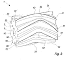
- Figs. 1-3 illustrate a preferred embodiment of a scraping roller 1 seen in perspective.
- the scraping roller 1 has opposing, substantially plane end surfaces 2, 3 and a peripheral surface 4 extending there between.
- the peripheral surface 4 comprises eight peripherally spaced teeth 10, 20, 30, 40, 50, 60, 70, 80 having U-shaped scraping edges 11, 21, 31, 41, 51, 61, 71, 81, the teeth 10, 20, 30, 40, 50, 60, 70, 80 extending from one end surface 2 to the other end surface 3 of the roller 1.
- the roller is provided with an axial bore 5 for receiving a driving shaft of a driving electric motor for rotating the roller around its centre axis to scrape the skin side of an animal pelt such as a mink pelt.
- the pelts are preferably tubular shaped mink pelts arranged on a mandrel with the skin surface facing outwards and the fur side facing inwards.
- the scraping roller 1 is preferably made from rubber (natural and/or synthetic rubber), a plastics material, and/or a similar resilient material or combinations of such materials.
- Preferred materials are polyurethane (PUR) and silicone rubber.
- the roller 1 is configured to be rotated in the direction indicated by an arrow 6. This means that the skin side of the pelt being treated will first come into engagement with the free outer ends of each scraping edge 11, 21, 31, 41, 51, 61, 71, 81 near the ends 2, 3 of the roller 1, and when the rotation of the roller proceeds, the points of engagement of each scraping edge 11, 21, 31, 41, 51, 61, 71, 81 will move towards the vertex 12, 22, 32, 42, 52, 62, 72, 82 of the U-shaped scraping edge 11, 21, 31, 41, 51, 61, 71, 81 and will tend to draw the fur towards this vertex 12, 22, 32, 42, 52, 62, 72, 82.
- the scraping edges 11, 21, 31, 41, 51, 61, 71, 81 are designed so that the distances from the vertices 12, 22, 32, 42, 52, 62, 72, 82 to a first end surface 2 of the roller 1 are varied gradually between a minimum distance and a maximum distance with an average distance of half the distance between the two end surfaces 2, 3 so that the difference in the longitudinal (i.e. axial) direction of the roller 1 of the position of the vertex between any two adjacent teeth 10, 20, 30, 40, 50, 60, 70, 80 is substantially the same.
- a first scraping edge 11 of a first tooth 10 with a vertex 12 at a minimum distance from the first end surface 2 comes into engagement with the skin side of the pelt, followed by a second tooth 20 having a scraping edge 21 with a vertex 22 that is a larger distance from the first end surface 2, a third tooth 30 having a scraping edge 31 with a vertex 32 that is a yet larger distance from the first end surface 2, a fourth tooth 40 and a fifth tooth 50 having a scraping edge 51 with a vertex 52 at the maximum distance from the first end surface.
- the distances in the axial i.e.
- the skin side of the pelt being treated by the roller 1 will be engaged by scraping edges 11, 21, 31, 41, 51, 61, 71, 81 with vertices 12, 22, 32, 42, 52, 62, 72, 82 where the transversal position of vertex of the engaging scraping edge is moved back and forth in a transversal reciprocal movement due to the transversal positioning of the vertices 12, 22, 32, 42, 52, 62, 72, 82 and the rotation of the roller 1.
- the reciprocal movement will have a centre around the middle of the roller 1 with deviations of plus or minus 15 millimetres from the middle of the 156 millimetres long roller 1, i.e. a deviation of plus or minus 10% of the length of the roller.
- the embodiments shown in the enclosed figures have a deviation of twice that magnitude for the sake of distinct illustration.
- the distances in the axial direction of the roller 1 from one end surface 2 to the position of the vertex12, 22, 32, 42, 52, 62, 72, 82 of the scraping edge 11, 21, 31, 41, 51, 61, 71, 81 of each of the eight teeth 10, 20, 30, 40, 50, 60, 70, 80 are for the preferred embodiment reproduced in the table, where the teeth are listed consecutively and the tooth with reference numeral 80 is followed by the tooth with reference numeral 10. Tooth reference numeral Distance (millimetres) in the axial direction of the roller 1 from one end surface 2 and to vertex 10 63 20 70.5 30 78 40 85.5 50 93 60 85.5 70 78 80 70.5
- the scraping edges 11, 21, 31, 41, 51, 61, 71, 81 are formed to be situated in a curved plane of a substantial cylindrical shape being coaxial with the roller 1.
- the teeth 10, 20, 30, 40, 50, 60, 70, 80 are formed so that they extend from one end surface 2 of the roller 1 to the other end surface 3 and so that the respective end portions of each scraping edge 11, 21, 31, 41, 51, 61, 71, 81 are positioned on the same generatrix of the substantial cylindrical curved plane in which the scraping edges are situated.
- the height of the vertex 12, 22, 32, 42, 52, 62, 72, 82 of the scraping edge 11, 21, 31, 41, 51, 61, 71, 81 is generally understood as the deviation of the vertex of the scraping edge from a straight scraping edge having the same basic position on the scraping roller.
- the height may de defined as the distance the vertex of the scraping edge deviates from a straight line going through the end portions of the scraping edge and being parallel to the axis of the roller.
- the height is defined as the distance between the generatrix passing through the end portions of a scraping edge and the generatrix passing through the vertex of the same scraping edge 11, 21, 31, 41, 51, 61, 71, 81.
- the U-shape or alternatively a V-shape of the arc-shape of the scraping edges 11, 21, 31, 41, 51, 61, 71, 81 is provided in order to avoiding rotation of the pelt and performing a temporary stretching of the pelt substantially perpendicular to the longitudinal direction of the mandrel.
- the above-mentioned apparent transversal reciprocal movement of the position of the vertex 12, 22, 32, 42, 52, 62, 72, 82 of the scraping edges 11, 21, 31, 41, 51, 61, 71, 81 that currently is engaging the skin side of the pelt treated by the roller 1 reduces the vibration-inducing effect by the roller 1 on the scraping apparatus at the main frequency, i.e. the number of rotations per second multiplied by the number of teeth on the roller 1.
- the roller 1 or rollers 1 of the apparatus may cause the apparatus to vibrate with an eigenfrequency of either the apparatus or a part of the apparatus. Such vibrations may influent negatively on the quality of the scraping, and/or may cause increased wear or fatigue on parts of the apparatus and the present roller 1 may reduce or avoid the occurrence of such vibrations.
- the teeth 10, 20, 30, 40, 50, 60, 70, 80 are formed so that they extend from one end surface 2 of the roller 1 to the other end surface 3 and so that the respective end portions of each scraping edge 11, 21, 31, 41, 51, 61, 71, 81 are positioned on the same generatrix of the
- the angular overlap has the effect that two adjacent teeth 10, 20, 30, 40, 50, 60, 70, 80 will be in engagement simultaneously with the skin side of the pelt for the time it takes the roller 1 to turn the angular overlap and the vibrations resulting from the use of the roller 1 will be reduced as a result thereof.
Landscapes
- Engineering & Computer Science (AREA)
- Mechanical Engineering (AREA)
- Chemical & Material Sciences (AREA)
- Organic Chemistry (AREA)
- Manufacturing & Machinery (AREA)
- Massaging Devices (AREA)
Description
- The invention relates to a scraping roller for scraping the skin side of an animal pelt.
- Various scraping rollers for apparatuses for scraping the skin side of an animal pelt such as a mink pelt are known.
-
US 4,745,782 discloses an apparatus with a scraping roller for scraping the skin side of an animal pelt. The scraping roller comprises a plurality of peripherally spaced teeth having scraping edges defining a substantially circular cylindrical surface. Each of the scraping edges is substantially V-shaped and defines an obtuse angle and the scraping edges are substantially symmetrical with respect to the central symmetry plane of the scraping roller. -
DK 173 611 B1 - Danish patent application No.
DK 2010 70431 - Scraping rollers with scraping edges are known to cause parts of the apparatus on which the scraping roller is arranged to vibrate unintentionally during operation, especially if the roller or rollers on the apparatus causes the apparatus to vibrate with an eigenfrequency of the apparatus or a part of the apparatus. Such vibrations may influent negatively on the quality of the scraping, and/or may cause increased wear on parts of the apparatus.
- It is an object of the present invention to reduce or avoid this problem of the known scraping rollers. It is a further object of the present invention to improve the design of the scraping roller in order to obtain a more satisfactory result of the scraping of the skin side of the furs by means of the scraping rollers.
- The present invention relates to a scraping roller for scraping the skin side of an animal pelt, according to
claim 1. - With the term axial position of the vertex is understood the position with respect to the axial direction of the roller and likewise, the axial distance is measured as the distance in the axial direction of the roller. Thus, the axial distance of a vertex from the first end of the scraping roller is the distance in the axial direction of the roller from the first end of the scraping roller and to the axial position of the vertex.
- The axial positions of the vertices of the scraping blades of a roller according to the present invention may comprise more than one maximum and one minimum, e.g. two of each with e.g. one or two intermediate teeth between each minimum and the consecutive maximum and between each maximum and the consecutive minimum, so that the roller comprises eight or twelve teeth, respectively. However, it is preferred that the axial positions of the vertices of the scraping blades of the roller comprise one maximum and one minimum only.
- The scraping edges are preferably continuous edges extending from one end of the scraping roller to the other, but the scraping edges may alternatively be provided with on or more openings along the extent thereof, such as at the vertex. In a particular embodiment, the parts of the scraping edges on the two sides of the vertex are displaced from each other in the angular direction of the roller at the vertex and define an opening there between, and the parts of the scraping edges may even be overlapping at the vertex.
- With the term vertex may be understood a sharp corner, in particular an obtuse angle between the parts of the scraping edge extending on each side of the vertex. In this case, the scraping edge is said to be of a V-shape. Alternatively, the vertex may be of a rounded shape, e.g. with a radius of curvature in the range of 15 to 40 millimetres, such as 20 to 30 millimetres, in which case the scraping edge is said to be of a U-shape.
- By arranging the scraping edges with different positions of the vertices as described above, it is possible to reduce or even avoid vibrations of the apparatus at an eigenfrequency of the apparatus. The different positions facilitates that the frequency spectre of the vibrations when the edges engages with the skin side may be spread over a range of frequencies defined e.g. by the rotation speed of the roller and the positions of the vertices.
- It is furthermore preferred that the scraping roller is provided with at least two intermediate teeth situated between the first tooth and the second tooth, and with at least two intermediate teeth situated between the second tooth and the first tooth. Thus, a satisfactory result may be obtained with at least six teeth on the roller, and the experience has shown that a number of teeth ranging from six to nine teeth is the most suitable number with eight teeth as the most preferred number of teeth.
- The difference in axial position of the vertex of the scraping edge between adjacent teeth of the scraping roller is in a preferred embodiment of the invention substantially the same for any pair of adjacent teeth. Hereby, a smooth operation of the scraping roller is obtained as the change in the engagement of the consecutive teeth with the skin side of the pelt is small.
- The difference between said minimum axial distance and said maximum axial distance is preferably in the range of 20 to 50 millimetres, preferably in the range of 25 to 40 millimetres.
- The height of the vertex of the scraping edges is preferably in the range of 20 to 40 millimetres, more preferably in the range of 25 to 35 millimetres.
- The height of the vertex of the scraping edge is generally understood as the deviation of the scraping edge at the position of the vertex from a straight scraping edge having the same basic position on the scraping roller. Thus, to define the height of the vertex of a scraping edge only makes sense when the end points of the scraping edge are situated substantially on one straight line that is parallel with the axis of the roller. However, it should be noted that the present invention is not generally limited to scraping rollers having teeth with such scraping edges, but it is a preferred embodiment of the scraping rollers according to the present invention.
- It has furthermore proven to be advantageous that the scraping edges are curved
- Moreover, the invention relates to use of a scraping roller as defined herein for scraping of the skin side of a pelt.
- Likewise, the invention relates to an apparatus for scraping of the skin side of mink pelts comprising one or more scraping rollers as defined herein.
- The invention will be described in the following with reference to the figures in which:
- Fig. 1
- illustrates a preferred embodiment of a scraping roller seen in perspective,
- Fig. 2
- illustrates the scraping roller of
fig. 1 seen in perspective from another angle, and - Fig. 3
- illustrates the scraping roller of
figs. 1 and2 seen from a further angle. -
Figs. 1-3 illustrate a preferred embodiment of ascraping roller 1 seen in perspective. Thescraping roller 1 has opposing, substantiallyplane end surfaces teeth scraping edges teeth end surface 2 to theother end surface 3 of theroller 1. - The roller is provided with an
axial bore 5 for receiving a driving shaft of a driving electric motor for rotating the roller around its centre axis to scrape the skin side of an animal pelt such as a mink pelt. The pelts are preferably tubular shaped mink pelts arranged on a mandrel with the skin surface facing outwards and the fur side facing inwards. - The
scraping roller 1 is preferably made from rubber (natural and/or synthetic rubber), a plastics material, and/or a similar resilient material or combinations of such materials. Preferred materials are polyurethane (PUR) and silicone rubber. - The
roller 1 is configured to be rotated in the direction indicated by anarrow 6. This means that the skin side of the pelt being treated will first come into engagement with the free outer ends of eachscraping edge ends roller 1, and when the rotation of the roller proceeds, the points of engagement of eachscraping edge vertex scraping edge vertex scraping edges vertices first end surface 2 of theroller 1 are varied gradually between a minimum distance and a maximum distance with an average distance of half the distance between the twoend surfaces roller 1 of the position of the vertex between any twoadjacent teeth - Thus, when the
roller 1 is rotated, afirst scraping edge 11 of afirst tooth 10 with avertex 12 at a minimum distance from thefirst end surface 2 comes into engagement with the skin side of the pelt, followed by asecond tooth 20 having ascraping edge 21 with avertex 22 that is a larger distance from thefirst end surface 2, athird tooth 30 having ascraping edge 31 with avertex 32 that is a yet larger distance from thefirst end surface 2, afourth tooth 40 and afifth tooth 50 having ascraping edge 51 with avertex 52 at the maximum distance from the first end surface. The distances in the axial (i.e. longitudinal) direction of theroller 1 from thevertices first end surface 2 are substantially evenly distributed so that the increase in distance is substantially the same between any twoadjacent vertices remaining teeth vertices first end surface 2 are substantially evenly distributed so that the decrease in distance from thefirst end surface 2 is substantially the same between any twoadjacent vertices - The skin side of the pelt being treated by the
roller 1 will be engaged byscraping edges vertices vertices roller 1. The reciprocal movement will have a centre around the middle of theroller 1 with deviations of plus or minus 15 millimetres from the middle of the 156 millimetreslong roller 1, i.e. a deviation of plus or minus 10% of the length of the roller. The embodiments shown in the enclosed figures have a deviation of twice that magnitude for the sake of distinct illustration. - Thus, the distances in the axial direction of the
roller 1 from oneend surface 2 to the position of the vertex12, 22, 32, 42, 52, 62, 72, 82 of the scrapingedge teeth reference numeral 80 is followed by the tooth withreference numeral 10.Tooth reference numeral Distance (millimetres) in the axial direction of the roller 1 from oneend surface 2 and tovertex 10 63 20 70.5 30 78 40 85.5 50 93 60 85.5 70 78 80 70.5 - The scraping edges 11, 21, 31, 41, 51, 61, 71, 81 are formed to be situated in a curved plane of a substantial cylindrical shape being coaxial with the
roller 1. - The
teeth end surface 2 of theroller 1 to theother end surface 3 and so that the respective end portions of each scrapingedge vertex edge same scraping edge - The U-shape or alternatively a V-shape of the arc-shape of the scraping edges 11, 21, 31, 41, 51, 61, 71, 81 is provided in order to avoiding rotation of the pelt and performing a temporary stretching of the pelt substantially perpendicular to the longitudinal direction of the mandrel. The above-mentioned apparent transversal reciprocal movement of the position of the
vertex roller 1 has the additional effect that the pelt is moved slightly back and forth in the transversal direction and at the same time is scraped with scrapingedges roller 1, the two effects resulting in an improved scraping of the skin side. - Furthermore, the above-mentioned apparent transversal reciprocal movement of the position of the
vertex roller 1 reduces the vibration-inducing effect by theroller 1 on the scraping apparatus at the main frequency, i.e. the number of rotations per second multiplied by the number of teeth on theroller 1. Theroller 1 orrollers 1 of the apparatus may cause the apparatus to vibrate with an eigenfrequency of either the apparatus or a part of the apparatus. Such vibrations may influent negatively on the quality of the scraping, and/or may cause increased wear or fatigue on parts of the apparatus and thepresent roller 1 may reduce or avoid the occurrence of such vibrations. - The
teeth end surface 2 of theroller 1 to theother end surface 3 and so that the respective end portions of each scrapingedge - In an alternative embodiment to the one shown in the enclosed figures, the
teeth edge teeth roller 1. The angular overlap has the effect that twoadjacent teeth roller 1 to turn the angular overlap and the vibrations resulting from the use of theroller 1 will be reduced as a result thereof. -
- 1:
- Scraping roller
- 2:
- First end surface of scraping roller
- 3:
- Second end surface of scraping roller
- 4:
- Peripheral surface
- 5:
- Axial bore
- 6:
- Rotation direction of scraping roller
- 10, 20, 30, 40, 50, 60, 70, 80:
- Teeth
- 11, 21, 31, 41, 51, 61, 71, 81:
- Scraping edges of teeth
- 12, 22, 32, 42, 52, 62, 72, 82:
- Vertex of scraping edges
Claims (11)
- A scraping roller (1) having an axis defining an axial direction for scraping the skin side of an animal pelt, said roller comprising a plurality of teeth (10, 20, 30, 40, 50, 60, 70, 80), each tooth comprising a scraping edge (11, 21, 31, 41, 51, 61, 71, 81) having a vertex (12, 22, 32, 42, 52, 62, 72, 82), said scraping edges being situated in a curved plane of a substantial cylindrical shape being coaxial with the roller, characterized in that the axial position of the vertex (12) of the scraping edge (11) of a first tooth (10) has a minimum axial distance from one end (2) of the scraping roller and the axial position of the vertex (52) of the scraping edge (51) of a second tooth (50) has a maximum axial distance from said one end (2) of the scraping roller, and
in that at least one of said plurality of teeth (20, 30, 40) is situated intermediate between said first tooth (10) and said second tooth (50) and at least one of said plurality of teeth (60, 70, 80) is situated intermediate between said second tooth (50) and said first tooth (10), these intermediately situated teeth (20, 30, 40, 60, 70, 80) being formed so that the axial position of the vertex of the scraping edge of successive teeth varies gradually between said minimum axial distance and said maximum axial distance. - A scraping roller according to claim 1, wherein at least two intermediate teeth (20, 30, 40) are situated between the first tooth and the second tooth, and at least two intermediate teeth (60, 70, 80) are situated between the second tooth and the first tooth.
- A scraping roller according to claim 1 or 2, wherein the difference in axial position of the vertex of the scraping edge between adjacent teeth of the scraping roller is substantially the same for any pair of adjacent teeth.
- A scraping roller according to any of the preceding claims, wherein the number of teeth is from 6 to 9, preferably 8.
- A scraping roller according to any of the preceding claims, wherein the difference between said minimum axial distance and said maximum axial distance is in the range of 20 to 50 millimetres, preferably in the range of 25 to 40 millimetres.
- A scraping roller according to any of the preceding claims, wherein the scraping edges are substantially of a U-shape.
- A scraping roller according to any of claims 1-5, wherein the scraping edges are substantially of a V-shape.
- A scraping roller according to any of the preceding claims, wherein the height of the vertex of the scraping edges are in the range of 20 to 40 millimetres, preferably in the range of 25 to 35 millimetres, the height of the wertex being defined as the distance the vertex of the scraping edge deviates from a straight line going through the end portions of the scraping edge and being parallel to the axis of the roller.
- A scraping roller according to any of the preceding claims, wherein the scraping edges are curved.
- Use of a scraping roller according to any of the claims 1 to 8 for scraping of the skin side of a pelt.
- An apparatus for scraping of the skin side of mink pelts comprising one or more scraping rollers according to any of claims 1-8.
Priority Applications (1)
| Application Number | Priority Date | Filing Date | Title |
|---|---|---|---|
| PL12181190T PL2562269T3 (en) | 2011-08-26 | 2012-08-21 | A scraping roller |
Applications Claiming Priority (1)
| Application Number | Priority Date | Filing Date | Title |
|---|---|---|---|
| DKPA201100644A DK177201B1 (en) | 2011-08-26 | 2011-08-26 | A scraping roller |
Publications (2)
| Publication Number | Publication Date |
|---|---|
| EP2562269A1 EP2562269A1 (en) | 2013-02-27 |
| EP2562269B1 true EP2562269B1 (en) | 2014-03-19 |
Family
ID=46160573
Family Applications (1)
| Application Number | Title | Priority Date | Filing Date |
|---|---|---|---|
| EP12181190.5A Not-in-force EP2562269B1 (en) | 2011-08-26 | 2012-08-21 | A scraping roller |
Country Status (3)
| Country | Link |
|---|---|
| EP (1) | EP2562269B1 (en) |
| DK (2) | DK177201B1 (en) |
| PL (1) | PL2562269T3 (en) |
Families Citing this family (3)
| Publication number | Priority date | Publication date | Assignee | Title |
|---|---|---|---|---|
| DK177580B1 (en) | 2012-08-30 | 2013-10-28 | Jasopels As | A scraping wheel and use of a scraping wheel |
| DK177867B1 (en) * | 2013-12-19 | 2014-10-13 | Jasopels As | Scraping roller with core part |
| EP3201363A1 (en) * | 2014-10-02 | 2017-08-09 | Eikon Technologies Holding S.à.r.l. | Apparatus and method for sharpening the scraping edges of a scraper roller |
Family Cites Families (4)
| Publication number | Priority date | Publication date | Assignee | Title |
|---|---|---|---|---|
| DK78286D0 (en) | 1986-02-20 | 1986-02-20 | Bent Juul Larsen | APPARATUS FOR REMOVAL OF FAT LAGES FROM THE COAT SIDE OF FUR SKIN |
| DK173611B1 (en) | 1998-06-15 | 2001-04-30 | Gjoel Pelsningsredskaber As | Process and apparatus for removing flesh and fat residues from the flesh side of pelts from fur-bearing animals |
| EP2093299B1 (en) * | 2008-02-21 | 2011-03-16 | Pamutec Patents ApS | Apparatus for processing fur |
| DK201000169U4 (en) | 2009-10-06 | 2011-05-13 | Pamutec Patents Aps | Scraper roll for cleaning fur skins |
-
2011
- 2011-08-26 DK DKPA201100644A patent/DK177201B1/en not_active IP Right Cessation
-
2012
- 2012-08-21 EP EP12181190.5A patent/EP2562269B1/en not_active Not-in-force
- 2012-08-21 PL PL12181190T patent/PL2562269T3/en unknown
- 2012-08-21 DK DK12181190.5T patent/DK2562269T3/en active
Also Published As
| Publication number | Publication date |
|---|---|
| DK2562269T3 (en) | 2014-06-02 |
| DK177201B1 (en) | 2012-06-04 |
| EP2562269A1 (en) | 2013-02-27 |
| PL2562269T3 (en) | 2014-08-29 |
Similar Documents
| Publication | Publication Date | Title |
|---|---|---|
| EP2562269A1 (en) | A scraping roller | |
| US9693568B2 (en) | Scrubber system | |
| US9125424B2 (en) | Method for making a filleting cut for filleting fish, device for making the filleting cut according to the method, and circular knife pair and circular knife set up for the method and the device | |
| EP2097219B1 (en) | Grinding surfaces of workpieces | |
| EP2255924A1 (en) | Method for calibrating surfaces of stone material | |
| US9670557B2 (en) | Scraping wheel, a scraping roller and use of a scraping wheel | |
| WO2015000791A1 (en) | Apparatus for processing of pelts having helical scraping rollers | |
| JP6190312B2 (en) | Device for removing hard deposits on shells | |
| WO2014032836A1 (en) | Helical scraping rollers and apparatus for processing of pelts having helical scraping rollers | |
| US12589413B2 (en) | Cleaning device for extension roller | |
| EP2853603A1 (en) | Apparatus for processing the flesh side of pelts | |
| US7959495B2 (en) | Method and apparatus for finishing the surface of rubber covered rollers | |
| US20160009501A1 (en) | Cleaning apparatus and cleaning method | |
| JP2023523535A (en) | Apparatus and method for longitudinally cutting ribbon-like food products, particularly ribbon-like cheese, into strips | |
| JP7154094B2 (en) | Manufacturing method of slide belt | |
| PT104943A (en) | METHOD AND DEVICE FOR BREAD TREATMENT | |
| JP5451002B2 (en) | Pitch alignment conveyor | |
| KR20170003730U (en) | Peering apparatus for pickled radish | |
| EP3091091B1 (en) | An apparatus with a pentagonal mandrel for processing pelts | |
| RU2331010C2 (en) | Method and device for unkinking partially kinked flexible rubber or synthetic rings | |
| RU2128570C1 (en) | Method for finish working of curvilinear products such as tubes | |
| JP2024515098A5 (en) | ||
| RU2004105751A (en) | METHOD FOR FORMING DIFFICULT PROFILE INTERCHANNEL CHANNELS OF GTC MONO-WHEEL AND TOOL FOR ITS IMPLEMENTATION | |
| SU1666541A1 (en) | Shaft of staker for treating hides and pelts | |
| JP2010023205A (en) | Polishing method for work, and polishing device |
Legal Events
| Date | Code | Title | Description |
|---|---|---|---|
| PUAI | Public reference made under article 153(3) epc to a published international application that has entered the european phase |
Free format text: ORIGINAL CODE: 0009012 |
|
| AK | Designated contracting states |
Kind code of ref document: A1 Designated state(s): AL AT BE BG CH CY CZ DE DK EE ES FI FR GB GR HR HU IE IS IT LI LT LU LV MC MK MT NL NO PL PT RO RS SE SI SK SM TR |
|
| AX | Request for extension of the european patent |
Extension state: BA ME |
|
| 17P | Request for examination filed |
Effective date: 20130628 |
|
| RBV | Designated contracting states (corrected) |
Designated state(s): AL AT BE BG CH CY CZ DE DK EE ES FI FR GB GR HR HU IE IS IT LI LT LU LV MC MK MT NL NO PL PT RO RS SE SI SK SM TR |
|
| RIC1 | Information provided on ipc code assigned before grant |
Ipc: C14B 15/00 20060101ALI20130716BHEP Ipc: C14B 1/02 20060101AFI20130716BHEP Ipc: C14B 17/02 20060101ALI20130716BHEP |
|
| GRAP | Despatch of communication of intention to grant a patent |
Free format text: ORIGINAL CODE: EPIDOSNIGR1 |
|
| RAP1 | Party data changed (applicant data changed or rights of an application transferred) |
Owner name: JASOPELS A/S |
|
| INTG | Intention to grant announced |
Effective date: 20131023 |
|
| GRAS | Grant fee paid |
Free format text: ORIGINAL CODE: EPIDOSNIGR3 |
|
| GRAA | (expected) grant |
Free format text: ORIGINAL CODE: 0009210 |
|
| AK | Designated contracting states |
Kind code of ref document: B1 Designated state(s): AL AT BE BG CH CY CZ DE DK EE ES FI FR GB GR HR HU IE IS IT LI LT LU LV MC MK MT NL NO PL PT RO RS SE SI SK SM TR |
|
| REG | Reference to a national code |
Ref country code: GB Ref legal event code: FG4D |
|
| REG | Reference to a national code |
Ref country code: CH Ref legal event code: EP |
|
| REG | Reference to a national code |
Ref country code: AT Ref legal event code: REF Ref document number: 657745 Country of ref document: AT Kind code of ref document: T Effective date: 20140415 |
|
| REG | Reference to a national code |
Ref country code: IE Ref legal event code: FG4D |
|
| REG | Reference to a national code |
Ref country code: DE Ref legal event code: R096 Ref document number: 602012001111 Country of ref document: DE Effective date: 20140430 |
|
| REG | Reference to a national code |
Ref country code: DK Ref legal event code: T3 Effective date: 20140526 |
|
| REG | Reference to a national code |
Ref country code: NL Ref legal event code: T3 |
|
| PG25 | Lapsed in a contracting state [announced via postgrant information from national office to epo] |
Ref country code: LT Free format text: LAPSE BECAUSE OF FAILURE TO SUBMIT A TRANSLATION OF THE DESCRIPTION OR TO PAY THE FEE WITHIN THE PRESCRIBED TIME-LIMIT Effective date: 20140319 Ref country code: NO Free format text: LAPSE BECAUSE OF FAILURE TO SUBMIT A TRANSLATION OF THE DESCRIPTION OR TO PAY THE FEE WITHIN THE PRESCRIBED TIME-LIMIT Effective date: 20140619 |
|
| REG | Reference to a national code |
Ref country code: AT Ref legal event code: MK05 Ref document number: 657745 Country of ref document: AT Kind code of ref document: T Effective date: 20140319 |
|
| REG | Reference to a national code |
Ref country code: LT Ref legal event code: MG4D |
|
| PG25 | Lapsed in a contracting state [announced via postgrant information from national office to epo] |
Ref country code: FI Free format text: LAPSE BECAUSE OF FAILURE TO SUBMIT A TRANSLATION OF THE DESCRIPTION OR TO PAY THE FEE WITHIN THE PRESCRIBED TIME-LIMIT Effective date: 20140319 Ref country code: SE Free format text: LAPSE BECAUSE OF FAILURE TO SUBMIT A TRANSLATION OF THE DESCRIPTION OR TO PAY THE FEE WITHIN THE PRESCRIBED TIME-LIMIT Effective date: 20140319 Ref country code: CY Free format text: LAPSE BECAUSE OF FAILURE TO SUBMIT A TRANSLATION OF THE DESCRIPTION OR TO PAY THE FEE WITHIN THE PRESCRIBED TIME-LIMIT Effective date: 20140319 |
|
| REG | Reference to a national code |
Ref country code: PL Ref legal event code: T3 |
|
| PG25 | Lapsed in a contracting state [announced via postgrant information from national office to epo] |
Ref country code: RS Free format text: LAPSE BECAUSE OF FAILURE TO SUBMIT A TRANSLATION OF THE DESCRIPTION OR TO PAY THE FEE WITHIN THE PRESCRIBED TIME-LIMIT Effective date: 20140319 Ref country code: HR Free format text: LAPSE BECAUSE OF FAILURE TO SUBMIT A TRANSLATION OF THE DESCRIPTION OR TO PAY THE FEE WITHIN THE PRESCRIBED TIME-LIMIT Effective date: 20140319 Ref country code: LV Free format text: LAPSE BECAUSE OF FAILURE TO SUBMIT A TRANSLATION OF THE DESCRIPTION OR TO PAY THE FEE WITHIN THE PRESCRIBED TIME-LIMIT Effective date: 20140319 |
|
| PG25 | Lapsed in a contracting state [announced via postgrant information from national office to epo] |
Ref country code: BE Free format text: LAPSE BECAUSE OF FAILURE TO SUBMIT A TRANSLATION OF THE DESCRIPTION OR TO PAY THE FEE WITHIN THE PRESCRIBED TIME-LIMIT Effective date: 20140319 Ref country code: BG Free format text: LAPSE BECAUSE OF FAILURE TO SUBMIT A TRANSLATION OF THE DESCRIPTION OR TO PAY THE FEE WITHIN THE PRESCRIBED TIME-LIMIT Effective date: 20140619 Ref country code: RO Free format text: LAPSE BECAUSE OF FAILURE TO SUBMIT A TRANSLATION OF THE DESCRIPTION OR TO PAY THE FEE WITHIN THE PRESCRIBED TIME-LIMIT Effective date: 20140319 Ref country code: IS Free format text: LAPSE BECAUSE OF FAILURE TO SUBMIT A TRANSLATION OF THE DESCRIPTION OR TO PAY THE FEE WITHIN THE PRESCRIBED TIME-LIMIT Effective date: 20140719 Ref country code: CZ Free format text: LAPSE BECAUSE OF FAILURE TO SUBMIT A TRANSLATION OF THE DESCRIPTION OR TO PAY THE FEE WITHIN THE PRESCRIBED TIME-LIMIT Effective date: 20140319 Ref country code: EE Free format text: LAPSE BECAUSE OF FAILURE TO SUBMIT A TRANSLATION OF THE DESCRIPTION OR TO PAY THE FEE WITHIN THE PRESCRIBED TIME-LIMIT Effective date: 20140319 |
|
| PG25 | Lapsed in a contracting state [announced via postgrant information from national office to epo] |
Ref country code: AT Free format text: LAPSE BECAUSE OF FAILURE TO SUBMIT A TRANSLATION OF THE DESCRIPTION OR TO PAY THE FEE WITHIN THE PRESCRIBED TIME-LIMIT Effective date: 20140319 Ref country code: SK Free format text: LAPSE BECAUSE OF FAILURE TO SUBMIT A TRANSLATION OF THE DESCRIPTION OR TO PAY THE FEE WITHIN THE PRESCRIBED TIME-LIMIT Effective date: 20140319 Ref country code: ES Free format text: LAPSE BECAUSE OF FAILURE TO SUBMIT A TRANSLATION OF THE DESCRIPTION OR TO PAY THE FEE WITHIN THE PRESCRIBED TIME-LIMIT Effective date: 20140319 |
|
| REG | Reference to a national code |
Ref country code: DE Ref legal event code: R097 Ref document number: 602012001111 Country of ref document: DE |
|
| PG25 | Lapsed in a contracting state [announced via postgrant information from national office to epo] |
Ref country code: PT Free format text: LAPSE BECAUSE OF FAILURE TO SUBMIT A TRANSLATION OF THE DESCRIPTION OR TO PAY THE FEE WITHIN THE PRESCRIBED TIME-LIMIT Effective date: 20140721 |
|
| PLBE | No opposition filed within time limit |
Free format text: ORIGINAL CODE: 0009261 |
|
| STAA | Information on the status of an ep patent application or granted ep patent |
Free format text: STATUS: NO OPPOSITION FILED WITHIN TIME LIMIT |
|
| 26N | No opposition filed |
Effective date: 20141222 |
|
| REG | Reference to a national code |
Ref country code: DE Ref legal event code: R119 Ref document number: 602012001111 Country of ref document: DE |
|
| PG25 | Lapsed in a contracting state [announced via postgrant information from national office to epo] |
Ref country code: LU Free format text: LAPSE BECAUSE OF FAILURE TO SUBMIT A TRANSLATION OF THE DESCRIPTION OR TO PAY THE FEE WITHIN THE PRESCRIBED TIME-LIMIT Effective date: 20140821 Ref country code: MC Free format text: LAPSE BECAUSE OF FAILURE TO SUBMIT A TRANSLATION OF THE DESCRIPTION OR TO PAY THE FEE WITHIN THE PRESCRIBED TIME-LIMIT Effective date: 20140319 Ref country code: IT Free format text: LAPSE BECAUSE OF FAILURE TO SUBMIT A TRANSLATION OF THE DESCRIPTION OR TO PAY THE FEE WITHIN THE PRESCRIBED TIME-LIMIT Effective date: 20140319 |
|
| REG | Reference to a national code |
Ref country code: DE Ref legal event code: R097 Ref document number: 602012001111 Country of ref document: DE Effective date: 20141222 |
|
| REG | Reference to a national code |
Ref country code: IE Ref legal event code: MM4A |
|
| REG | Reference to a national code |
Ref country code: DE Ref legal event code: R119 Ref document number: 602012001111 Country of ref document: DE Effective date: 20150303 |
|
| REG | Reference to a national code |
Ref country code: FR Ref legal event code: ST Effective date: 20150430 |
|
| PG25 | Lapsed in a contracting state [announced via postgrant information from national office to epo] |
Ref country code: SI Free format text: LAPSE BECAUSE OF FAILURE TO SUBMIT A TRANSLATION OF THE DESCRIPTION OR TO PAY THE FEE WITHIN THE PRESCRIBED TIME-LIMIT Effective date: 20140319 Ref country code: DE Free format text: LAPSE BECAUSE OF NON-PAYMENT OF DUE FEES Effective date: 20150303 |
|
| PG25 | Lapsed in a contracting state [announced via postgrant information from national office to epo] |
Ref country code: FR Free format text: LAPSE BECAUSE OF NON-PAYMENT OF DUE FEES Effective date: 20140901 Ref country code: IE Free format text: LAPSE BECAUSE OF NON-PAYMENT OF DUE FEES Effective date: 20140821 |
|
| REG | Reference to a national code |
Ref country code: CH Ref legal event code: PL |
|
| PG25 | Lapsed in a contracting state [announced via postgrant information from national office to epo] |
Ref country code: CH Free format text: LAPSE BECAUSE OF NON-PAYMENT OF DUE FEES Effective date: 20150831 Ref country code: LI Free format text: LAPSE BECAUSE OF NON-PAYMENT OF DUE FEES Effective date: 20150831 |
|
| PG25 | Lapsed in a contracting state [announced via postgrant information from national office to epo] |
Ref country code: SM Free format text: LAPSE BECAUSE OF FAILURE TO SUBMIT A TRANSLATION OF THE DESCRIPTION OR TO PAY THE FEE WITHIN THE PRESCRIBED TIME-LIMIT Effective date: 20140319 |
|
| PG25 | Lapsed in a contracting state [announced via postgrant information from national office to epo] |
Ref country code: GR Free format text: LAPSE BECAUSE OF FAILURE TO SUBMIT A TRANSLATION OF THE DESCRIPTION OR TO PAY THE FEE WITHIN THE PRESCRIBED TIME-LIMIT Effective date: 20140620 Ref country code: MT Free format text: LAPSE BECAUSE OF FAILURE TO SUBMIT A TRANSLATION OF THE DESCRIPTION OR TO PAY THE FEE WITHIN THE PRESCRIBED TIME-LIMIT Effective date: 20140319 |
|
| PG25 | Lapsed in a contracting state [announced via postgrant information from national office to epo] |
Ref country code: TR Free format text: LAPSE BECAUSE OF FAILURE TO SUBMIT A TRANSLATION OF THE DESCRIPTION OR TO PAY THE FEE WITHIN THE PRESCRIBED TIME-LIMIT Effective date: 20140319 Ref country code: HU Free format text: LAPSE BECAUSE OF FAILURE TO SUBMIT A TRANSLATION OF THE DESCRIPTION OR TO PAY THE FEE WITHIN THE PRESCRIBED TIME-LIMIT; INVALID AB INITIO Effective date: 20120821 |
|
| REG | Reference to a national code |
Ref country code: NL Ref legal event code: PD Owner name: EIKON TECHNOLOGIES HOLDING S.A.R.L.; LU Free format text: DETAILS ASSIGNMENT: VERANDERING VAN EIGENAAR(S), OVERDRACHT; FORMER OWNER NAME: JASOPELS A/S Effective date: 20160414 |
|
| GBPC | Gb: european patent ceased through non-payment of renewal fee |
Effective date: 20160821 |
|
| PG25 | Lapsed in a contracting state [announced via postgrant information from national office to epo] |
Ref country code: GB Free format text: LAPSE BECAUSE OF NON-PAYMENT OF DUE FEES Effective date: 20160821 |
|
| PGFP | Annual fee paid to national office [announced via postgrant information from national office to epo] |
Ref country code: NL Payment date: 20170814 Year of fee payment: 6 |
|
| PGFP | Annual fee paid to national office [announced via postgrant information from national office to epo] |
Ref country code: DK Payment date: 20170810 Year of fee payment: 6 |
|
| PG25 | Lapsed in a contracting state [announced via postgrant information from national office to epo] |
Ref country code: MK Free format text: LAPSE BECAUSE OF FAILURE TO SUBMIT A TRANSLATION OF THE DESCRIPTION OR TO PAY THE FEE WITHIN THE PRESCRIBED TIME-LIMIT Effective date: 20140319 |
|
| PGFP | Annual fee paid to national office [announced via postgrant information from national office to epo] |
Ref country code: PL Payment date: 20180612 Year of fee payment: 7 |
|
| PG25 | Lapsed in a contracting state [announced via postgrant information from national office to epo] |
Ref country code: AL Free format text: LAPSE BECAUSE OF FAILURE TO SUBMIT A TRANSLATION OF THE DESCRIPTION OR TO PAY THE FEE WITHIN THE PRESCRIBED TIME-LIMIT Effective date: 20140319 |
|
| REG | Reference to a national code |
Ref country code: DK Ref legal event code: EBP Effective date: 20180831 |
|
| REG | Reference to a national code |
Ref country code: NL Ref legal event code: MM Effective date: 20180901 |
|
| PG25 | Lapsed in a contracting state [announced via postgrant information from national office to epo] |
Ref country code: NL Free format text: LAPSE BECAUSE OF NON-PAYMENT OF DUE FEES Effective date: 20180901 |
|
| PG25 | Lapsed in a contracting state [announced via postgrant information from national office to epo] |
Ref country code: DK Free format text: LAPSE BECAUSE OF NON-PAYMENT OF DUE FEES Effective date: 20180831 |
|
| PG25 | Lapsed in a contracting state [announced via postgrant information from national office to epo] |
Ref country code: PL Free format text: LAPSE BECAUSE OF NON-PAYMENT OF DUE FEES Effective date: 20190821 |