EP2561342B1 - Ultrasonic transducer with wear plate - Google Patents
Ultrasonic transducer with wear plate Download PDFInfo
- Publication number
- EP2561342B1 EP2561342B1 EP11709779.0A EP11709779A EP2561342B1 EP 2561342 B1 EP2561342 B1 EP 2561342B1 EP 11709779 A EP11709779 A EP 11709779A EP 2561342 B1 EP2561342 B1 EP 2561342B1
- Authority
- EP
- European Patent Office
- Prior art keywords
- wear plate
- piezoelectric element
- ultrasonic transducer
- transducer
- transducer according
- Prior art date
- Legal status (The legal status is an assumption and is not a legal conclusion. Google has not performed a legal analysis and makes no representation as to the accuracy of the status listed.)
- Active
Links
Images




Classifications
-
- H—ELECTRICITY
- H10—SEMICONDUCTOR DEVICES; ELECTRIC SOLID-STATE DEVICES NOT OTHERWISE PROVIDED FOR
- H10N—ELECTRIC SOLID-STATE DEVICES NOT OTHERWISE PROVIDED FOR
- H10N30/00—Piezoelectric or electrostrictive devices
- H10N30/80—Constructional details
- H10N30/88—Mounts; Supports; Enclosures; Casings
- H10N30/883—Additional insulation means preventing electrical, physical or chemical damage, e.g. protective coatings
-
- G—PHYSICS
- G01—MEASURING; TESTING
- G01N—INVESTIGATING OR ANALYSING MATERIALS BY DETERMINING THEIR CHEMICAL OR PHYSICAL PROPERTIES
- G01N29/00—Investigating or analysing materials by the use of ultrasonic, sonic or infrasonic waves; Visualisation of the interior of objects by transmitting ultrasonic or sonic waves through the object
- G01N29/04—Analysing solids
- G01N29/07—Analysing solids by measuring propagation velocity or propagation time of acoustic waves
-
- G—PHYSICS
- G01—MEASURING; TESTING
- G01N—INVESTIGATING OR ANALYSING MATERIALS BY DETERMINING THEIR CHEMICAL OR PHYSICAL PROPERTIES
- G01N29/00—Investigating or analysing materials by the use of ultrasonic, sonic or infrasonic waves; Visualisation of the interior of objects by transmitting ultrasonic or sonic waves through the object
- G01N29/22—Details, e.g. general constructional or apparatus details
- G01N29/228—Details, e.g. general constructional or apparatus details related to high temperature conditions
-
- G—PHYSICS
- G01—MEASURING; TESTING
- G01N—INVESTIGATING OR ANALYSING MATERIALS BY DETERMINING THEIR CHEMICAL OR PHYSICAL PROPERTIES
- G01N29/00—Investigating or analysing materials by the use of ultrasonic, sonic or infrasonic waves; Visualisation of the interior of objects by transmitting ultrasonic or sonic waves through the object
- G01N29/22—Details, e.g. general constructional or apparatus details
- G01N29/24—Probes
- G01N29/2437—Piezoelectric probes
-
- G—PHYSICS
- G01—MEASURING; TESTING
- G01N—INVESTIGATING OR ANALYSING MATERIALS BY DETERMINING THEIR CHEMICAL OR PHYSICAL PROPERTIES
- G01N29/00—Investigating or analysing materials by the use of ultrasonic, sonic or infrasonic waves; Visualisation of the interior of objects by transmitting ultrasonic or sonic waves through the object
- G01N29/22—Details, e.g. general constructional or apparatus details
- G01N29/26—Arrangements for orientation or scanning by relative movement of the head and the sensor
- G01N29/265—Arrangements for orientation or scanning by relative movement of the head and the sensor by moving the sensor relative to a stationary material
-
- G—PHYSICS
- G01—MEASURING; TESTING
- G01N—INVESTIGATING OR ANALYSING MATERIALS BY DETERMINING THEIR CHEMICAL OR PHYSICAL PROPERTIES
- G01N29/00—Investigating or analysing materials by the use of ultrasonic, sonic or infrasonic waves; Visualisation of the interior of objects by transmitting ultrasonic or sonic waves through the object
- G01N29/22—Details, e.g. general constructional or apparatus details
- G01N29/32—Arrangements for suppressing undesired influences, e.g. temperature or pressure variations, compensating for signal noise
-
- G—PHYSICS
- G10—MUSICAL INSTRUMENTS; ACOUSTICS
- G10K—SOUND-PRODUCING DEVICES; METHODS OR DEVICES FOR PROTECTING AGAINST, OR FOR DAMPING, NOISE OR OTHER ACOUSTIC WAVES IN GENERAL; ACOUSTICS NOT OTHERWISE PROVIDED FOR
- G10K11/00—Methods or devices for transmitting, conducting or directing sound in general; Methods or devices for protecting against, or for damping, noise or other acoustic waves in general
- G10K11/004—Mounting transducers, e.g. provided with mechanical moving or orienting device
-
- G—PHYSICS
- G01—MEASURING; TESTING
- G01N—INVESTIGATING OR ANALYSING MATERIALS BY DETERMINING THEIR CHEMICAL OR PHYSICAL PROPERTIES
- G01N2291/00—Indexing codes associated with group G01N29/00
- G01N2291/02—Indexing codes associated with the analysed material
- G01N2291/028—Material parameters
- G01N2291/0289—Internal structure, e.g. defects, grain size, texture
-
- G—PHYSICS
- G01—MEASURING; TESTING
- G01N—INVESTIGATING OR ANALYSING MATERIALS BY DETERMINING THEIR CHEMICAL OR PHYSICAL PROPERTIES
- G01N2291/00—Indexing codes associated with group G01N29/00
- G01N2291/26—Scanned objects
- G01N2291/263—Surfaces
- G01N2291/2634—Surfaces cylindrical from outside
Definitions
- the present invention relates to an ultrasonic transducer particularly, but not exclusively, for use in inspecting pipes using guided ultrasonic waves.
- Ultrasonic waves can be used for inspecting a structure, such as a pipe, to identify defects and flaws within the structure. Examples of ultrasonic inspection devices can be found in WO 96/12951 A , WO 2007/125308 A2 and EP 1 394 538 A1
- WO 96/12951 A describes apparatus for inspecting elongate members, such as pipes.
- the apparatus includes a ring of angularly-spaced transducers (or “exciters") clamped to the outside wall of a pipe.
- Each transducer includes a piezoelectric element, a metal block adhesively bonded to the piezoelectric element, and a thin faceplate shim secured to the face of the piezoelectric element to provide a wear plate.
- the piezoelectric element and wear plate are stacked in a recess in the metal block and secured using an epoxy adhesive. This arrangement can have disadvantages.
- the sides of the wear plate may be constrained by the sides of the recess. This can decrease the efficiency of the transducer.
- the metal block is near the pipe. If the pipe is hot, then the metal block can absorb heat radiated by the pipe and heat the piezoelectric element and the epoxy adhesive. Piezoelectric elements have a maximum operating temperature and so this arrangement can limit the maximum temperature of pipe that can be inspected using the transducer.
- both the front of the metal block and the wear plate are exposed to high temperatures. If the metal block and wear plate are made from different materials, then they may expand at different rates dues to different coefficients of thermal expansion. This can limit the maximum operating temperature of the transducer and reduce the number of operation cycles.
- the bond line between the metal block and the wear plate is at the front of the transducer and so is usually exposed to the environment. This can limit the lifetime of the transducer and/or make it less reliable due to exposure to the environment, for example due to ingress of sea water. Furthermore, if the pipe is hot, then the epoxy adhesive is directly exposed to heating.
- US 5 016 474 A describes a transducer comprising a piezoelectric element which is received within a blind bore in a wear reference member.
- the wear reference member is received within the through bore so that its end is substantially flush with the inner surface of the wear member.
- the inner surface of the wear member is machined to ensure that the end of the wear reference member is flush with the inner surface.
- US 5 140 860 describes electrodynamic transducer head which has at least two detachably arranged probes are allocated to one pole shoe of a magnet, and are covered by a common protective plate.
- the transducer head can be used for nondestructive testing of workpieces using ultrasound, for which purpose a cap of the transducer head has sliding blocks which rest on the workpiece.
- EP 2 036 620 A1 describes an ultrasonic transducer which includes piezoelectric elements, a pair of clamping members which clamp the piezoelectric elements and a cover member which is crimped to at least one of said pair of clamping members in a state where said cover member cooperates with said pair of clamping members to surround said piezoelectric elements.
- EP 1 698 894 A2 describes apparatus for inspecting a pipe using guided ultrasonic waves includes a signal processing arrangement.
- the present invention seems to provide an improved ultrasonic transducer.
- an ultrasonic transducer including a wear plate, a piezoelectric element arranged rearwards of the wear plate and a rigid block arranged rearwards of the piezoelectric element and which is configured to provide a backing mass for the piezoelectric element, wherein the wear plate extends across the piezoelectric element and rearwards so as to provide a cap over the piezoelectric element and sides of at least a forward portion of the rigid block.
- the wear plate has a forward face and rearwards face.
- the piezoelectric element is a shear-polarized piezoelectric element and the forward face is shaped to provide a knife edge or sharp ridge.
- This transducer can have one or more advantages.
- the arrangement can allow the wear plate to move more freely and, thus, increase the efficiency of the transducer.
- the wear plate can shield the metal block from a hot structure, such as a hot pipe.
- a hot structure such as a hot pipe.
- the wear plate is made from a material which is a poor thermal conductor, this can allow a hotter structure to be inspected and/or to be inspected for longer.
- the region of the transducer which is closest to the structure under inspection is made from the same material which can help to reduce the problem of different parts expanding at different rates.
- a larger piezoelectric element can be used since it is not constrained by the size of a recess in the backing mass.
- the knife edge or sharp ridge can allow the wear plate to cut through or pierce a coating covering a pipe and contact an underlying structure.
- the wear plate can comprise a material which is material which is a poor thermal conductor, such as a ceramic. This can help to reduce heating of the piezoelectric element if the transducer is in contact with a hot object.
- the wear plate may comprise a laminate including a layer of ceramic and/or metal or metal alloy.
- the wear plate may have a thickness of at least 1 mm.
- the ultrasonic transducer may further comprise a thermally-conductive element disposed between the wear plate and the piezoelectric element for conducting heat absorbed by the wear plate.
- the thermally-conductive element comprises a layer of thermally-conductive material disposed on a rearward surface of the wear plate. This can help to reduce heating of the piezoelectric element if the transducer is in contact with a hot object.
- the ultrasonic transducer may further comprise another piezoelectric element.
- the other piezoelectric element may be arranged between the piezoelectric element and the rigid block in a stack. Thus, different orientations or magnitudes of motion can be generated.
- the ultrasonic transducer may further comprise a filler, such as an adhesive, arranged to encapsulate the piezoelectric element and the forward portion of the rigid block.
- a filler such as an adhesive
- apparatus for inspecting an elongate member comprising a plurality of ultrasonic transducers, the ultrasonic transducers may be arranged in a band around the elongate member.
- the apparatus may be configured to inspect a pipe and the ultrasonic transducers may be angularly spaced in a ring around an exterior wall of the pipe.
- a method of operating the ultrasonic transducer comprising placing the wear plate in contact with the elongate member and applying an electrical signal to the piezoelectric element.
- the ultrasonic transducer may be urged against the elongate member.
- an ultrasonic transducer assembly 1 (herein simply referred to as an "ultrasonic transducer”) is shown.
- the ultrasonic transducer 1 includes a wear plate 2 (which may also be referred to as a "face plate” or “contact head”) having a front surface 3 which, in use, is pressed into contact with an object or structure (not shown) under inspection, and a rear surface 4 ( Figure 6 ).
- the wear plate 2 is made from a ceramic, such as zirconium dioxide (ZiO 2 ) or aluminium oxide (Al 2 O 3 ), or other suitable material which is a poor thermal conductor.
- the material may have a value of thermal conductivity, k, equal to or less than 25 Wm -1 K -1 , equal to or less than 10 Wm -1 K -1 , equal to or less than 5 Wm -1 K -1 or equal to or less than 2 Wm -1 K -1 .
- the wear plate 2 can be made from a metal or a metal alloy.
- An arched heat-extracting strip 5 (or "heat sink") runs behind the wear plate 2.
- the strip 5 comprises a metal or thermally highly-conductive material, such as copper, aluminium, gold or silver.
- the material may have a value of thermal conductivity, k, equal to or greater than 200 Wm -1 K -1 .
- the heat-extracting strip 5 can be omitted, particularly if the object or structure under inspection is at or close to ambient temperature.
- the ultrasonic transducer 1 includes a first transducer stack 6 which comprises a first earth electrode 7 which is closest to the wear plate 2, a first active layer 8 in the form of a shear polarized piezoelectric layer and a first signal electrode 9.
- a first electrical insulating layer or plate 10 separates the first transducer stack 6 from a second transducer stack 11.
- the second transducer stack 11 comprises a second earth electrode 12, a second active 13 layer also in the form a shear polarized piezoelectric layer and a second signal electrode 14.
- a second electrical insulating layer 15 separates the second transducer stack 11 from a rigid block 16 which provides a non-resonant backing mass.
- the rigid block 16 is preferably made of steel or other dense material so as to provide a high mass. The material may be chosen so as to have a low coefficient of thermal expansion or one which is matched to the wear plate.
- First and second miniature coaxial cables 17, 18 provide connections to the first and second pairs of electrodes 7, 9, 12, 14 respectively.
- the cables 17, 18 sit in recesses 19, 20 running down opposite sides of the rigid block 16.
- the piezoelectric elements 8, 13 are stacked such that their polarizations cross, e.g. perpendicularly, by rotating the direction of one layer 8 relative to the other 13 and are separately controlled. Being able to generate different orientations of shear motion, e.g. along the x-axis or along the y-axis, allows different types of guided wave modes to be generated and received by the transducer 1, thereby avoiding the need for two different sets of transducer elements for the different orientations.
- the piezoelectric elements 8, 13 can be stacked having the same polarization and wired in parallel in order to increase the maximum deflection generated by a given voltage. This can increase the signal-to-noise ratio by injecting larger signals into the pipe.
- the transducer need only have one piezoelectric element.
- the second transducer stack 11, second electrical insulating layer 15 and second coaxial cable 18 can be omitted.
- the wear plate 2 passes in front (as shown, the top) of the rest of the transducer and to the rear (as shown, down) to provide a cap over a forward-most portion of the heat-extracting strip 5, the transducer stacks 6, 11 and the insulating plates 10, 15.
- the wear plate 2 also extends beyond a front face 24 of the rigid block 16 and along the sides 24 of a forward portion (as shown, a top portion) of the rigid block 16.
- the wear plate 2 is shaped to provide a space or recess 27 in which the forward-most portion of the heat-extracting strip 5, the transducer stacks 6, 11, the insulating plates 10, 15 and the top part of the rigid block 16 sit.
- the wear plate 2 may be machined or moulded.
- the wear plate 2 may have a thickness, t, of material equal to or greater than 1 mm or equal to or greater than 2 mm. As shown in Figure 3 , the thickness, t, is behind the point (or region) which comes into contact with the structure under test. In this example, the thickness is in the middle of the wear plate 2 and is where the wear plate 2 is thickest.
- the wear plate 2 may be thinner where it is not in contact with the structure under test. Increasing the thickness of the wear plate 2 between the point of contact and the active layer 8 can help to increase thermal insulation and, thus, reduce heating of the active layer 8.
- the rest of the space 27 ( Figure 3 ) is filled with a flexible filler 28 (hereing also referred to as an "encapsulate”), for example an epoxy adhesive or potting compound, so as to encapsulate the forward-most portion of the heat-extracting strip 5, transducer stacks 6, 11, insulating plates 10, 15 and the top part of the rigid block 16.
- the filler 28 may be a poor thermal conductor.
- the transducer 1 can be used in an apparatus or method for inspecting pipes as described in WO 96/12951 A and WO 2007/125308 A2 .
- the transducer 1 can offer several advantages, particularly when inspecting hot pipe and/or being used in harsh environments.
- the wear plate 2 can shield the rigid block 16 from heat.
- the part of the transducer 1 that is closest to the hot pipe - and which suffers the largest rapid temperature rise - is made from the same material. Thus, it is possible to sustain a large temperature gradient across the thickness (along the z-direction) of the wear plate 2.
- the heat-extracting strip 5 allows heat to be transmitted away from the piezoelectric layers 8, 13.
- One or both ends of the strip 5 can be connected to a heat sink or heat exchange (not shown). This arrangement can help to protect sensitive piezoelectric layers 8, 13 from high temperatures.
- the underside of the wear plate 2, the forward-most portion of the heat-extracting strip 5, transducer stacks 6, 11, insulating plates 10, 15 and forward-most portion of the rigid block 16 can be encapsulated to provide a watertight seal.
- the entire transducer with the exception of a small portion of the wear plate 2 around a contact region, can be completely encapsulated to further enhance environmental protection.
- the active element is not fitted inside a recess in the rigid block, a larger active element can be used.
- the area of the active element can be as large as the rigid block. This can aid assembly, as well as improving efficiency of the transducer.
- the front 3 of the wear plate 2 can be shaped to have a specific profile. For example, this can provide greater freedom of movement for the wear plate 2. Furthermore, the shape of the front 3 of the wear plate 2 can be optimised to maximise the use of air flow (or flow of some other fluid) to cool the transducer 1. For example, the shape of the front 3 of the wear plate 2 can be arranged so as maximise its surface area. Thus, air can be blown across the front 3 of the wear plate 2 to cool it. Moreover, the profile of the front 3 of the wear plate 2 can be configured, e.g. by keeping it smooth, to reduce turbulent air flow which can generate noise.
- the shape of the front 3 of the wear plate 2 can be changed in order to modify the contact area with a pipe.
- the wear plate 2 is shaped to provide a sharp contact area 30, in the form of a knife edge or sharp ridge. This allows the wear plate 2 to cut through or pierce a plastic coating (not shown) covering a pipe (not shown) and contact an underlying metal wall of the pipe (not shown).
- the wear plate 2 comprises a tough material, such as a hard, non-brittle ceramic, a metal or metal alloy, such as stainless steel or tungsten carbide.
- the wear plate 2 may comprise a ceramic, such as ZiO 2 or Al 2 O 3 , or other suitable material which is a poor thermal conductor.
- the wear plate 2 can be a laminate, e.g. comprising a metal layer and an overlying layer of ceramic.
- the wear plate 2 may have a thickness, t, equal to or greater than 1 mm or equal to or greater than 2 mm.
- the wear plate 2 is shown from the rear.
- the rear surface 4 of the wear plate 2 provides a recess having a stepped wall.
- the axial contact length can be smaller than the diameter of the rigid block 16 ( Figure 1 ).
- a narrow contact profile allows the transducer to be tilted more.
- a modified wear plate 2' is shown which is shaped to provide a wide contact area 30'. This can be used to increase coupling between the pipe and the transducer.
- the transducer need not include a heat-extracting strip 5 ( Figure 1 ) or a second piezoelectric layer 13 ( Figure 1 ).
- the heat-extracting layer can be omitted if the transducer is to be used to inspect cool objects.
- FIG 9 shows another transducer 1'.
- the transducer 1' is similar to the transducer 1 ( Figure 1 ) described earlier, but does not have a heat-extracting layer.
- FIG 10 shows yet another transducer 1".
- the transducer 1" is similar to the transducer 1 ( Figure 1 ) described earlier, but has only one piezoelectric layer 10. Thus, the transducer 1" does not have a second transducer stack 11 including the second earth electrode 12, the second active 13 layer and the second signal electrode 14. The transducer 1" also does not have a second electrical insulating layer 15 and a second coaxial cable 18.
- FIG 11 shows still yet another transducer 1"'.
- the transducer 1" is similar to the transducer 1" ( Figure 10 ) described earlier, but does not have a heat-extracting layer. In some of the embodiments, a heat-extracting strip is used. Additionally or alternatively, the rear 4 ( Figure 3 ) of the faceplate 2 can be coated, e.g. by electroplating, with a highly thermally-conductive coating, such as copper.
- the ultrasonic transducer may be a different type of direct contact ultrasonic transducer.
- the wear plate may be made as thick as possible provided it still transmits significant force across the interface into the test component.
Landscapes
- Physics & Mathematics (AREA)
- Biochemistry (AREA)
- Immunology (AREA)
- Pathology (AREA)
- Health & Medical Sciences (AREA)
- Life Sciences & Earth Sciences (AREA)
- Chemical & Material Sciences (AREA)
- General Physics & Mathematics (AREA)
- General Health & Medical Sciences (AREA)
- Analytical Chemistry (AREA)
- Acoustics & Sound (AREA)
- Engineering & Computer Science (AREA)
- Multimedia (AREA)
- Investigating Or Analyzing Materials By The Use Of Ultrasonic Waves (AREA)
- General Electrical Machinery Utilizing Piezoelectricity, Electrostriction Or Magnetostriction (AREA)
- Transducers For Ultrasonic Waves (AREA)
Description
- The present invention relates to an ultrasonic transducer particularly, but not exclusively, for use in inspecting pipes using guided ultrasonic waves.
- Ultrasonic waves can be used for inspecting a structure, such as a pipe, to identify defects and flaws within the structure. Examples of ultrasonic inspection devices can be found in
WO 96/12951 A WO 2007/125308 A2 andEP 1 394 538 A1 -
WO 96/12951 A - In the prior art transducer, the piezoelectric element and wear plate are stacked in a recess in the metal block and secured using an epoxy adhesive. This arrangement can have disadvantages.
- Firstly, the sides of the wear plate may be constrained by the sides of the recess. This can decrease the efficiency of the transducer.
- Secondly, the metal block is near the pipe. If the pipe is hot, then the metal block can absorb heat radiated by the pipe and heat the piezoelectric element and the epoxy adhesive. Piezoelectric elements have a maximum operating temperature and so this arrangement can limit the maximum temperature of pipe that can be inspected using the transducer.
- Thirdly, when inspecting a hot pipe, both the front of the metal block and the wear plate are exposed to high temperatures. If the metal block and wear plate are made from different materials, then they may expand at different rates dues to different coefficients of thermal expansion. This can limit the maximum operating temperature of the transducer and reduce the number of operation cycles.
- Finally, the bond line between the metal block and the wear plate is at the front of the transducer and so is usually exposed to the environment. This can limit the lifetime of the transducer and/or make it less reliable due to exposure to the environment, for example due to ingress of sea water. Furthermore, if the pipe is hot, then the epoxy adhesive is directly exposed to heating.
-
US 5 016 474 A describes a transducer comprising a piezoelectric element which is received within a blind bore in a wear reference member. The wear reference member is received within the through bore so that its end is substantially flush with the inner surface of the wear member. The inner surface of the wear member is machined to ensure that the end of the wear reference member is flush with the inner surface. -
US 5 140 860 describes electrodynamic transducer head which has at least two detachably arranged probes are allocated to one pole shoe of a magnet, and are covered by a common protective plate. The transducer head can be used for nondestructive testing of workpieces using ultrasound, for which purpose a cap of the transducer head has sliding blocks which rest on the workpiece. -
EP 2 036 620 A1 -
EP 1 698 894 A2 - The present invention seems to provide an improved ultrasonic transducer.
- According to the present invention there is provided an ultrasonic transducer including a wear plate, a piezoelectric element arranged rearwards of the wear plate and a rigid block arranged rearwards of the piezoelectric element and which is configured to provide a backing mass for the piezoelectric element, wherein the wear plate extends across the piezoelectric element and rearwards so as to provide a cap over the piezoelectric element and sides of at least a forward portion of the rigid block. The wear plate has a forward face and rearwards face. The piezoelectric element is a shear-polarized piezoelectric element and the forward face is shaped to provide a knife edge or sharp ridge.
- This transducer can have one or more advantages. The arrangement can allow the wear plate to move more freely and, thus, increase the efficiency of the transducer. Furthermore, the wear plate can shield the metal block from a hot structure, such as a hot pipe. Thus, if the wear plate is made from a material which is a poor thermal conductor, this can allow a hotter structure to be inspected and/or to be inspected for longer. Moreover, the region of the transducer which is closest to the structure under inspection is made from the same material which can help to reduce the problem of different parts expanding at different rates. In addition, a larger piezoelectric element can be used since it is not constrained by the size of a recess in the backing mass.
The knife edge or sharp ridge can allow the wear plate to cut through or pierce a coating covering a pipe and contact an underlying structure. - The wear plate can comprise a material which is material which is a poor thermal conductor, such as a ceramic. This can help to reduce heating of the piezoelectric element if the transducer is in contact with a hot object.
- The wear plate may comprise a laminate including a layer of ceramic and/or metal or metal alloy.
- The wear plate may have a thickness of at least 1 mm.
- The ultrasonic transducer may further comprise a thermally-conductive element disposed between the wear plate and the piezoelectric element for conducting heat absorbed by the wear plate. The thermally-conductive element comprises a layer of thermally-conductive material disposed on a rearward surface of the wear plate. This can help to reduce heating of the piezoelectric element if the transducer is in contact with a hot object.
- The ultrasonic transducer may further comprise another piezoelectric element. The other piezoelectric element may be arranged between the piezoelectric element and the rigid block in a stack. Thus, different orientations or magnitudes of motion can be generated.
- The ultrasonic transducer may further comprise a filler, such as an adhesive, arranged to encapsulate the piezoelectric element and the forward portion of the rigid block.
- According to a second aspect of the present invention there is provided apparatus for inspecting an elongate member, the apparatus comprising a plurality of ultrasonic transducers, the ultrasonic transducers may be arranged in a band around the elongate member.
- The apparatus may be configured to inspect a pipe and the ultrasonic transducers may be angularly spaced in a ring around an exterior wall of the pipe.
- According to a third aspect of the present invention there is provided a method of operating the ultrasonic transducer comprising placing the wear plate in contact with the elongate member and applying an electrical signal to the piezoelectric element. The ultrasonic transducer may be urged against the elongate member.
- Certain embodiments of the present invention will now be described, by way of example, with reference to the accompanying drawings in which:
-
Figure 1 is an exploded perspective view of an ultrasonic transducer assembly; -
Figure 2 is a part cutaway perspective view of the ultrasonic transducer shown inFigure 1 ; -
Figure 2a is a perspective view of the ultrasonic transducer shown inFigure 1 ; -
Figure 3 is a cross sectional view of the ultrasonic transducer shown inFigure 1 taken along the line A-A'; -
Figure 4 is a part cutaway perspective view of an encapsulated ultrasonic transducer; -
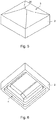
Figure 5 is a perspective view of a wear plate according to the invention, having a knife edge contact region from above; -
Figure 6 is a perspective view of the wear plate shown inFigure 5 from below; -
Figure 7 is a perspective view of a wear plate having a blunt contact region from above; -
Figure 8 is a perspective view of the wear plate shown inFigure 7 from below; -
Figure 9 is a part cutaway perspective view of an ultrasonic transducer without a heat-extracting strip; -
Figure 10 is a part cutaway perspective view of an ultrasonic transducer with a single active element and a heat-extracting strip; and -
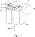
Figure 11 is a part cutaway perspective view of an ultrasonic transducer with a single active element and without a heat-extracting strip. - In the following, like parts are denoted by like reference numerals.
- Referring to
Figures 1 ,2 ,2a ,3 and 4 , an ultrasonic transducer assembly 1 (herein simply referred to as an "ultrasonic transducer") is shown. - The
ultrasonic transducer 1 includes a wear plate 2 (which may also be referred to as a "face plate" or "contact head") having afront surface 3 which, in use, is pressed into contact with an object or structure (not shown) under inspection, and a rear surface 4 (Figure 6 ). Thewear plate 2 is made from a ceramic, such as zirconium dioxide (ZiO2) or aluminium oxide (Al2O3), or other suitable material which is a poor thermal conductor. The material may have a value of thermal conductivity, k, equal to or less than 25 Wm-1K-1, equal to or less than 10 Wm-1K-1, equal to or less than 5 Wm-1K-1 or equal to or less than 2 Wm-1K-1. However, in some embodiments, thewear plate 2 can be made from a metal or a metal alloy. An arched heat-extracting strip 5 (or "heat sink") runs behind thewear plate 2. Thestrip 5 comprises a metal or thermally highly-conductive material, such as copper, aluminium, gold or silver. The material may have a value of thermal conductivity, k, equal to or greater than 200 Wm-1K-1. The heat-extractingstrip 5 can be omitted, particularly if the object or structure under inspection is at or close to ambient temperature. - The
ultrasonic transducer 1 includes afirst transducer stack 6 which comprises afirst earth electrode 7 which is closest to thewear plate 2, a firstactive layer 8 in the form of a shear polarized piezoelectric layer and afirst signal electrode 9. - A first electrical insulating layer or
plate 10 separates thefirst transducer stack 6 from asecond transducer stack 11. Thesecond transducer stack 11 comprises asecond earth electrode 12, a second active 13 layer also in the form a shear polarized piezoelectric layer and asecond signal electrode 14. - A second electrical insulating
layer 15 separates thesecond transducer stack 11 from arigid block 16 which provides a non-resonant backing mass. Therigid block 16 is preferably made of steel or other dense material so as to provide a high mass. The material may be chosen so as to have a low coefficient of thermal expansion or one which is matched to the wear plate. - First and second miniature
coaxial cables electrodes cables recesses rigid block 16. - As shown in
Figure 1 , thepiezoelectric elements layer 8 relative to the other 13 and are separately controlled. Being able to generate different orientations of shear motion, e.g. along the x-axis or along the y-axis, allows different types of guided wave modes to be generated and received by thetransducer 1, thereby avoiding the need for two different sets of transducer elements for the different orientations. - Notwithstanding this, the
piezoelectric elements - Moreover, as will be shown later, the transducer need only have one piezoelectric element. Thus, for example, the
second transducer stack 11, second electrical insulatinglayer 15 and secondcoaxial cable 18 can be omitted. - Referring in particular to
Figure 3 , thewear plate 2 passes in front (as shown, the top) of the rest of the transducer and to the rear (as shown, down) to provide a cap over a forward-most portion of the heat-extractingstrip 5, the transducer stacks 6, 11 and the insulatingplates wear plate 2 also extends beyond afront face 24 of therigid block 16 and along thesides 24 of a forward portion (as shown, a top portion) of therigid block 16. - The
wear plate 2 is shaped to provide a space orrecess 27 in which the forward-most portion of the heat-extractingstrip 5, the transducer stacks 6, 11, the insulatingplates rigid block 16 sit. Thewear plate 2 may be machined or moulded.
Thewear plate 2 may have a thickness, t, of material equal to or greater than 1 mm or equal to or greater than 2 mm. As shown inFigure 3 , the thickness, t, is behind the point (or region) which comes into contact with the structure under test. In this example, the thickness is in the middle of thewear plate 2 and is where thewear plate 2 is thickest. Thewear plate 2 may be thinner where it is not in contact with the structure under test. Increasing the thickness of thewear plate 2 between the point of contact and theactive layer 8 can help to increase thermal insulation and, thus, reduce heating of theactive layer 8. - Referring in particular to
Figure 4 , the rest of the space 27 (Figure 3 ) is filled with a flexible filler 28 (hereing also referred to as an "encapsulate"), for example an epoxy adhesive or potting compound, so as to encapsulate the forward-most portion of the heat-extractingstrip 5,transducer stacks plates rigid block 16. Thefiller 28 may be a poor thermal conductor. Referring still toFigures 1 ,2 ,2a ,3 and 4 , thetransducer 1 can be used in an apparatus or method for inspecting pipes as described inWO 96/12951 A WO 2007/125308 A2 . - The
transducer 1 can offer several advantages, particularly when inspecting hot pipe and/or being used in harsh environments.
When thefront 3 of thewear plate 2 is presented to a hot object, such as a hot pipe, thewear plate 2 can shield therigid block 16 from heat. Furthermore, the part of thetransducer 1 that is closest to the hot pipe - and which suffers the largest rapid temperature rise - is made from the same material. Thus, it is possible to sustain a large temperature gradient across the thickness (along the z-direction) of thewear plate 2. - The heat-extracting
strip 5 allows heat to be transmitted away from thepiezoelectric layers strip 5 can be connected to a heat sink or heat exchange (not shown). This arrangement can help to protect sensitivepiezoelectric layers - The underside of the
wear plate 2, the forward-most portion of the heat-extractingstrip 5,transducer stacks plates rigid block 16 can be encapsulated to provide a watertight seal. In fact, the entire transducer, with the exception of a small portion of thewear plate 2 around a contact region, can be completely encapsulated to further enhance environmental protection. - Because the active element is not fitted inside a recess in the rigid block, a larger active element can be used. For example, the area of the active element can be as large as the rigid block. This can aid assembly, as well as improving efficiency of the transducer.
- The
front 3 of thewear plate 2 can be shaped to have a specific profile. For example, this can provide greater freedom of movement for thewear plate 2. Furthermore, the shape of thefront 3 of thewear plate 2 can be optimised to maximise the use of air flow (or flow of some other fluid) to cool thetransducer 1. For example, the shape of thefront 3 of thewear plate 2 can be arranged so as maximise its surface area. Thus, air can be blown across thefront 3 of thewear plate 2 to cool it. Moreover, the profile of thefront 3 of thewear plate 2 can be configured, e.g. by keeping it smooth, to reduce turbulent air flow which can generate noise. - The shape of the
front 3 of thewear plate 2 can be changed in order to modify the contact area with a pipe. - Referring in particular to
Figure 5 , thewear plate 2 is shaped to provide asharp contact area 30, in the form of a knife edge or sharp ridge. This allows thewear plate 2 to cut through or pierce a plastic coating (not shown) covering a pipe (not shown) and contact an underlying metal wall of the pipe (not shown). Preferably, thewear plate 2 comprises a tough material, such as a hard, non-brittle ceramic, a metal or metal alloy, such as stainless steel or tungsten carbide. As mentioned earlier, thewear plate 2 may comprise a ceramic, such as ZiO2 or Al2O3, or other suitable material which is a poor thermal conductor. Thewear plate 2 can be a laminate, e.g. comprising a metal layer and an overlying layer of ceramic. Thewear plate 2 may have a thickness, t, equal to or greater than 1 mm or equal to or greater than 2 mm. - In
Figure 6 , thewear plate 2 is shown from the rear. Therear surface 4 of thewear plate 2 provides a recess having a stepped wall. - The axial contact length can be smaller than the diameter of the rigid block 16 (
Figure 1 ). A narrow contact profile allows the transducer to be tilted more. Referring in particular toFigure 7 , a modified wear plate 2' is shown which is shaped to provide a wide contact area 30'. This can be used to increase coupling between the pipe and the transducer. - As explained earlier, the transducer need not include a heat-extracting strip 5 (
Figure 1 ) or a second piezoelectric layer 13 (Figure 1 ). For example, the heat-extracting layer can be omitted if the transducer is to be used to inspect cool objects. -
Figure 9 shows another transducer 1'. The transducer 1' is similar to the transducer 1 (Figure 1 ) described earlier, but does not have a heat-extracting layer. -
Figure 10 shows yet anothertransducer 1". Thetransducer 1" is similar to the transducer 1 (Figure 1 ) described earlier, but has only onepiezoelectric layer 10. Thus, thetransducer 1" does not have asecond transducer stack 11 including thesecond earth electrode 12, the second active 13 layer and thesecond signal electrode 14. Thetransducer 1" also does not have a second electrical insulatinglayer 15 and a secondcoaxial cable 18. -
Figure 11 shows still yet anothertransducer 1"'. Thetransducer 1" is similar to thetransducer 1" (Figure 10 ) described earlier, but does not have a heat-extracting layer. In some of the embodiments, a heat-extracting strip is used. Additionally or alternatively, the rear 4 (Figure 3 ) of thefaceplate 2 can be coated, e.g. by electroplating, with a highly thermally-conductive coating, such as copper. - The ultrasonic transducer may be a different type of direct contact ultrasonic transducer.
The wear plate may be made as thick as possible provided it still transmits significant force across the interface into the test component.
Claims (12)
- An ultrasonic transducer including:a wear plate (2);a piezoelectric element (8) arranged rearwards of the wear plate; anda rigid block (16) arranged rearwards of the piezoelectric element and configured to provide a backing mass for the piezoelectric element;wherein the wear plate extends across the piezoelectric element and rearwards so as to provide a cap over the piezoelectric element and sides of at least a forward portion of the rigid block wherein the wear plate has a forward face (3) and rearwards face (4) and characterised in that the piezoelectric element (8) is a shear-polarized piezoelectric element and the forward face is shaped to provide a knife edge or sharp ridge.
- An ultrasonic transducer according to claim 1, wherein the wear plate comprises a material which is a poor thermal conductor.
- An ultrasonic transducer according to claim 1 or 2, wherein the wear plate (2) comprises a ceramic.
- An ultrasonic transducer according to any preceding claim, further comprising a thermally-conductive element (5) disposed between the wear plate (2) and the piezoelectric element (8) for conducting away heat absorbed by the wear plate.
- An ultrasonic transducer according to claim 4, wherein thermally-conductive element (5) comprises a layer of thermally-conductive material disposed on rearwards surface of the wear plate.
- An ultrasonic transducer according to any preceding claim, wherein the wear plate has thickness of at least 1 mm.
- An ultrasonic transducer according to any preceding claim, further comprising another piezoelectric element (13).
- An ultrasonic transducer according to claim 7, wherein the other piezoelectric element (13) is arranged between the piezoelectric element (8) and the rigid block (16) in a stack.
- An ultrasonic transducer according to any preceding claim, further comprising a filler (28), such as an adhesive, arranged to encapsulate the piezoelectric element (8) and the forward portion (26) of the rigid block (16).
- Apparatus for inspecting an elongate member, the apparatus comprising a plurality of ultrasonic transducers according to any preceding claim, the ultrasonic transducers arranged in a band around the elongate member.
- Apparatus according to claim 10, wherein the apparatus is configured to inspect a pipe and the ultrasonic transducer are angularly spaced in a ring around an exterior wall of the pipe.
- A method of operating a transducer according to any one of claims 1 to 9 comprising:placing the wear plate in contact with the elongate member; andapplying an electrical signal to the piezoelectric element (8).
Applications Claiming Priority (3)
| Application Number | Priority Date | Filing Date | Title |
|---|---|---|---|
| GB1006571A GB2479744A (en) | 2010-04-20 | 2010-04-20 | Ultrasonic transducer |
| GBGB1015609.9A GB201015609D0 (en) | 2010-04-20 | 2010-09-17 | Ultrasonic transducer |
| PCT/GB2011/050395 WO2011131954A2 (en) | 2010-04-20 | 2011-02-28 | Ultrasonic transducer |
Publications (2)
| Publication Number | Publication Date |
|---|---|
| EP2561342A2 EP2561342A2 (en) | 2013-02-27 |
| EP2561342B1 true EP2561342B1 (en) | 2017-05-10 |
Family
ID=42245478
Family Applications (1)
| Application Number | Title | Priority Date | Filing Date |
|---|---|---|---|
| EP11709779.0A Active EP2561342B1 (en) | 2010-04-20 | 2011-02-28 | Ultrasonic transducer with wear plate |
Country Status (4)
| Country | Link |
|---|---|
| US (1) | US9065038B2 (en) |
| EP (1) | EP2561342B1 (en) |
| GB (2) | GB2479744A (en) |
| WO (1) | WO2011131954A2 (en) |
Families Citing this family (6)
| Publication number | Priority date | Publication date | Assignee | Title |
|---|---|---|---|---|
| US9243381B2 (en) * | 2013-04-19 | 2016-01-26 | Caterpillar Inc. | Erosion monitoring system for ground engaging tool |
| WO2015012420A1 (en) * | 2013-07-23 | 2015-01-29 | 알피니언메디칼시스템 주식회사 | Ultrasonic probe |
| GB2568371B (en) * | 2017-11-10 | 2020-04-15 | Guided Ultrasonics Ltd | Ultrasonic transducer |
| GB2568273B (en) | 2017-11-10 | 2020-04-01 | Guided Ultrasonics Ltd | Ultrasonic transducer |
| US11366552B2 (en) | 2018-02-06 | 2022-06-21 | Apple, Inc. | Ultrasonic polarizer |
| US20250347658A1 (en) * | 2024-05-08 | 2025-11-13 | Rtx Corporation | Resonance inspection system and method for using same |
Family Cites Families (13)
| Publication number | Priority date | Publication date | Assignee | Title |
|---|---|---|---|---|
| DE3401072C2 (en) * | 1984-01-13 | 1986-04-10 | Nukem Gmbh, 6450 Hanau | Electrodynamic transducer head |
| GB8420244D0 (en) * | 1984-08-09 | 1984-09-12 | Shell Int Research | Transducing device |
| US4641520A (en) * | 1984-08-23 | 1987-02-10 | The United States Of America As Represented By The United States Department Of Energy | Shear wave transducer for stress measurements in boreholes |
| US4649749A (en) * | 1985-02-19 | 1987-03-17 | J. W. Harley Pump Works, Inc. | Ultrasonic tranducer |
| US5016474A (en) | 1985-02-19 | 1991-05-21 | J. W. Harley Inc. | Ultrasonic transducer |
| DE4002100A1 (en) * | 1990-01-25 | 1991-08-08 | Nukem Gmbh | ELECTRODYNAMIC CONVERTER HEAD |
| DE4304548C2 (en) * | 1992-04-02 | 1994-11-24 | Mannesmann Ag | Test head for non-destructive testing |
| US5619423A (en) * | 1994-01-21 | 1997-04-08 | Scrantz; Leonard | System, method and apparatus for the ultrasonic inspection of liquid filled tubulars and vessels |
| GB0504500D0 (en) | 2005-03-04 | 2005-04-13 | Guided Ultrasonics Ltd | Signal processing arrangement |
| US7975555B2 (en) * | 2005-12-01 | 2011-07-12 | California Institute Of Technology | Apparatus for simultaneously measuring longitudinal and shear wave speeds in materials under compression load via an ultrasonic transducer |
| US7546770B2 (en) * | 2006-01-05 | 2009-06-16 | General Electric Company | Electromagnetic acoustic transducer |
| GB2437547B (en) * | 2006-04-28 | 2010-07-14 | Genesis Oil And Gas Consultant | Method and apparatus for inspecting pipes |
| US7876030B2 (en) | 2007-09-11 | 2011-01-25 | Ngk Spark Plug Co., Ltd. | Ultrasonic transducer which is either crimped or welded during assembly |
-
2010
- 2010-04-20 GB GB1006571A patent/GB2479744A/en not_active Withdrawn
- 2010-09-17 GB GBGB1015609.9A patent/GB201015609D0/en not_active Ceased
-
2011
- 2011-02-28 EP EP11709779.0A patent/EP2561342B1/en active Active
- 2011-02-28 US US13/640,946 patent/US9065038B2/en active Active
- 2011-02-28 WO PCT/GB2011/050395 patent/WO2011131954A2/en not_active Ceased
Also Published As
| Publication number | Publication date |
|---|---|
| WO2011131954A2 (en) | 2011-10-27 |
| US20130127296A1 (en) | 2013-05-23 |
| US9065038B2 (en) | 2015-06-23 |
| GB2479744A (en) | 2011-10-26 |
| EP2561342A2 (en) | 2013-02-27 |
| WO2011131954A3 (en) | 2012-05-18 |
| GB201015609D0 (en) | 2010-10-27 |
| GB201006571D0 (en) | 2010-06-02 |
Similar Documents
| Publication | Publication Date | Title |
|---|---|---|
| US9065038B2 (en) | Transducer assembly | |
| Kažys et al. | High temperature ultrasonic transducers | |
| JP4624659B2 (en) | Ultrasonic probe | |
| US8232705B2 (en) | Thermal transfer and acoustic matching layers for ultrasound transducer | |
| JP5342608B2 (en) | Apparatus and system for measuring material thickness | |
| US8378557B2 (en) | Thermal transfer and acoustic matching layers for ultrasound transducer | |
| JP6552644B2 (en) | Impedance matching layer for ultrasonic transducers with metallic protective structure | |
| US20200107814A1 (en) | Ultrasound transducer and method for wafer level back face attachment | |
| CN110487908B (en) | Elastic constant measuring method based on array magnet electromagnetic ultrasound | |
| CN203787081U (en) | Underwater acoustic transducer | |
| CN107249763A (en) | Sonic transducer including multiple single transducers and the method for its manufacture | |
| JP2013029492A (en) | Multi-part mounting device for ultrasonic transducer | |
| CA2799731C (en) | Device for measuring material thickness | |
| KR102193194B1 (en) | Hydrophone, energy conversion method and complex hydrophone | |
| EP3808277B1 (en) | Ultrasound transducer, ultrasonic probe, and ultrasonic detection apparatus | |
| CN209474649U (en) | A kind of ultrasonic probe and ultrasonic plane array probe | |
| CN210170072U (en) | an ultrasonic probe | |
| CN114280585A (en) | High-frequency broadband multi-beam receiving array and manufacturing method thereof | |
| US20240053300A1 (en) | Ultrasonic structural health monitoring device, system and method | |
| JP2003004713A (en) | High temperature sensor | |
| CN110960258A (en) | an ultrasonic probe | |
| JP5788530B2 (en) | Apparatus and method for mounting active device on solid substrate | |
| JP2008200155A (en) | Ultrasonic probe | |
| CN118004429A (en) | Ice detection device and detection method | |
| Pedrick et al. | Design and Performance of a Broadband 10MHz Transducer for Elevated Temperature, Leave-in-Place Applications |
Legal Events
| Date | Code | Title | Description |
|---|---|---|---|
| PUAI | Public reference made under article 153(3) epc to a published international application that has entered the european phase |
Free format text: ORIGINAL CODE: 0009012 |
|
| 17P | Request for examination filed |
Effective date: 20121011 |
|
| AK | Designated contracting states |
Kind code of ref document: A2 Designated state(s): AL AT BE BG CH CY CZ DE DK EE ES FI FR GB GR HR HU IE IS IT LI LT LU LV MC MK MT NL NO PL PT RO RS SE SI SK SM TR |
|
| DAX | Request for extension of the european patent (deleted) | ||
| GRAP | Despatch of communication of intention to grant a patent |
Free format text: ORIGINAL CODE: EPIDOSNIGR1 |
|
| STAA | Information on the status of an ep patent application or granted ep patent |
Free format text: STATUS: GRANT OF PATENT IS INTENDED |
|
| INTG | Intention to grant announced |
Effective date: 20170104 |
|
| GRAS | Grant fee paid |
Free format text: ORIGINAL CODE: EPIDOSNIGR3 |
|
| GRAA | (expected) grant |
Free format text: ORIGINAL CODE: 0009210 |
|
| STAA | Information on the status of an ep patent application or granted ep patent |
Free format text: STATUS: THE PATENT HAS BEEN GRANTED |
|
| AK | Designated contracting states |
Kind code of ref document: B1 Designated state(s): AL AT BE BG CH CY CZ DE DK EE ES FI FR GB GR HR HU IE IS IT LI LT LU LV MC MK MT NL NO PL PT RO RS SE SI SK SM TR |
|
| REG | Reference to a national code |
Ref country code: GB Ref legal event code: FG4D |
|
| REG | Reference to a national code |
Ref country code: AT Ref legal event code: REF Ref document number: 892880 Country of ref document: AT Kind code of ref document: T Effective date: 20170515 Ref country code: CH Ref legal event code: EP |
|
| REG | Reference to a national code |
Ref country code: IE Ref legal event code: FG4D |
|
| REG | Reference to a national code |
Ref country code: DE Ref legal event code: R096 Ref document number: 602011037782 Country of ref document: DE |
|
| REG | Reference to a national code |
Ref country code: NL Ref legal event code: MP Effective date: 20170510 |
|
| REG | Reference to a national code |
Ref country code: LT Ref legal event code: MG4D |
|
| REG | Reference to a national code |
Ref country code: AT Ref legal event code: MK05 Ref document number: 892880 Country of ref document: AT Kind code of ref document: T Effective date: 20170510 |
|
| PG25 | Lapsed in a contracting state [announced via postgrant information from national office to epo] |
Ref country code: ES Free format text: LAPSE BECAUSE OF FAILURE TO SUBMIT A TRANSLATION OF THE DESCRIPTION OR TO PAY THE FEE WITHIN THE PRESCRIBED TIME-LIMIT Effective date: 20170510 Ref country code: GR Free format text: LAPSE BECAUSE OF FAILURE TO SUBMIT A TRANSLATION OF THE DESCRIPTION OR TO PAY THE FEE WITHIN THE PRESCRIBED TIME-LIMIT Effective date: 20170811 Ref country code: AT Free format text: LAPSE BECAUSE OF FAILURE TO SUBMIT A TRANSLATION OF THE DESCRIPTION OR TO PAY THE FEE WITHIN THE PRESCRIBED TIME-LIMIT Effective date: 20170510 Ref country code: LT Free format text: LAPSE BECAUSE OF FAILURE TO SUBMIT A TRANSLATION OF THE DESCRIPTION OR TO PAY THE FEE WITHIN THE PRESCRIBED TIME-LIMIT Effective date: 20170510 Ref country code: NO Free format text: LAPSE BECAUSE OF FAILURE TO SUBMIT A TRANSLATION OF THE DESCRIPTION OR TO PAY THE FEE WITHIN THE PRESCRIBED TIME-LIMIT Effective date: 20170810 Ref country code: HR Free format text: LAPSE BECAUSE OF FAILURE TO SUBMIT A TRANSLATION OF THE DESCRIPTION OR TO PAY THE FEE WITHIN THE PRESCRIBED TIME-LIMIT Effective date: 20170510 Ref country code: FI Free format text: LAPSE BECAUSE OF FAILURE TO SUBMIT A TRANSLATION OF THE DESCRIPTION OR TO PAY THE FEE WITHIN THE PRESCRIBED TIME-LIMIT Effective date: 20170510 |
|
| PG25 | Lapsed in a contracting state [announced via postgrant information from national office to epo] |
Ref country code: LV Free format text: LAPSE BECAUSE OF FAILURE TO SUBMIT A TRANSLATION OF THE DESCRIPTION OR TO PAY THE FEE WITHIN THE PRESCRIBED TIME-LIMIT Effective date: 20170510 Ref country code: SE Free format text: LAPSE BECAUSE OF FAILURE TO SUBMIT A TRANSLATION OF THE DESCRIPTION OR TO PAY THE FEE WITHIN THE PRESCRIBED TIME-LIMIT Effective date: 20170510 Ref country code: PL Free format text: LAPSE BECAUSE OF FAILURE TO SUBMIT A TRANSLATION OF THE DESCRIPTION OR TO PAY THE FEE WITHIN THE PRESCRIBED TIME-LIMIT Effective date: 20170510 Ref country code: IS Free format text: LAPSE BECAUSE OF FAILURE TO SUBMIT A TRANSLATION OF THE DESCRIPTION OR TO PAY THE FEE WITHIN THE PRESCRIBED TIME-LIMIT Effective date: 20170910 Ref country code: RS Free format text: LAPSE BECAUSE OF FAILURE TO SUBMIT A TRANSLATION OF THE DESCRIPTION OR TO PAY THE FEE WITHIN THE PRESCRIBED TIME-LIMIT Effective date: 20170510 Ref country code: NL Free format text: LAPSE BECAUSE OF FAILURE TO SUBMIT A TRANSLATION OF THE DESCRIPTION OR TO PAY THE FEE WITHIN THE PRESCRIBED TIME-LIMIT Effective date: 20170510 Ref country code: BG Free format text: LAPSE BECAUSE OF FAILURE TO SUBMIT A TRANSLATION OF THE DESCRIPTION OR TO PAY THE FEE WITHIN THE PRESCRIBED TIME-LIMIT Effective date: 20170810 |
|
| PG25 | Lapsed in a contracting state [announced via postgrant information from national office to epo] |
Ref country code: SK Free format text: LAPSE BECAUSE OF FAILURE TO SUBMIT A TRANSLATION OF THE DESCRIPTION OR TO PAY THE FEE WITHIN THE PRESCRIBED TIME-LIMIT Effective date: 20170510 Ref country code: RO Free format text: LAPSE BECAUSE OF FAILURE TO SUBMIT A TRANSLATION OF THE DESCRIPTION OR TO PAY THE FEE WITHIN THE PRESCRIBED TIME-LIMIT Effective date: 20170510 Ref country code: CZ Free format text: LAPSE BECAUSE OF FAILURE TO SUBMIT A TRANSLATION OF THE DESCRIPTION OR TO PAY THE FEE WITHIN THE PRESCRIBED TIME-LIMIT Effective date: 20170510 Ref country code: DK Free format text: LAPSE BECAUSE OF FAILURE TO SUBMIT A TRANSLATION OF THE DESCRIPTION OR TO PAY THE FEE WITHIN THE PRESCRIBED TIME-LIMIT Effective date: 20170510 Ref country code: EE Free format text: LAPSE BECAUSE OF FAILURE TO SUBMIT A TRANSLATION OF THE DESCRIPTION OR TO PAY THE FEE WITHIN THE PRESCRIBED TIME-LIMIT Effective date: 20170510 |
|
| REG | Reference to a national code |
Ref country code: DE Ref legal event code: R097 Ref document number: 602011037782 Country of ref document: DE |
|
| REG | Reference to a national code |
Ref country code: FR Ref legal event code: PLFP Year of fee payment: 8 |
|
| PG25 | Lapsed in a contracting state [announced via postgrant information from national office to epo] |
Ref country code: SM Free format text: LAPSE BECAUSE OF FAILURE TO SUBMIT A TRANSLATION OF THE DESCRIPTION OR TO PAY THE FEE WITHIN THE PRESCRIBED TIME-LIMIT Effective date: 20170510 |
|
| PLBE | No opposition filed within time limit |
Free format text: ORIGINAL CODE: 0009261 |
|
| STAA | Information on the status of an ep patent application or granted ep patent |
Free format text: STATUS: NO OPPOSITION FILED WITHIN TIME LIMIT |
|
| 26N | No opposition filed |
Effective date: 20180213 |
|
| PG25 | Lapsed in a contracting state [announced via postgrant information from national office to epo] |
Ref country code: SI Free format text: LAPSE BECAUSE OF FAILURE TO SUBMIT A TRANSLATION OF THE DESCRIPTION OR TO PAY THE FEE WITHIN THE PRESCRIBED TIME-LIMIT Effective date: 20170510 |
|
| REG | Reference to a national code |
Ref country code: CH Ref legal event code: PL |
|
| PG25 | Lapsed in a contracting state [announced via postgrant information from national office to epo] |
Ref country code: MC Free format text: LAPSE BECAUSE OF FAILURE TO SUBMIT A TRANSLATION OF THE DESCRIPTION OR TO PAY THE FEE WITHIN THE PRESCRIBED TIME-LIMIT Effective date: 20170510 |
|
| REG | Reference to a national code |
Ref country code: IE Ref legal event code: MM4A |
|
| REG | Reference to a national code |
Ref country code: BE Ref legal event code: MM Effective date: 20180228 |
|
| PG25 | Lapsed in a contracting state [announced via postgrant information from national office to epo] |
Ref country code: CH Free format text: LAPSE BECAUSE OF NON-PAYMENT OF DUE FEES Effective date: 20180228 Ref country code: LU Free format text: LAPSE BECAUSE OF NON-PAYMENT OF DUE FEES Effective date: 20180228 Ref country code: LI Free format text: LAPSE BECAUSE OF NON-PAYMENT OF DUE FEES Effective date: 20180228 |
|
| PG25 | Lapsed in a contracting state [announced via postgrant information from national office to epo] |
Ref country code: IE Free format text: LAPSE BECAUSE OF NON-PAYMENT OF DUE FEES Effective date: 20180228 |
|
| PG25 | Lapsed in a contracting state [announced via postgrant information from national office to epo] |
Ref country code: BE Free format text: LAPSE BECAUSE OF NON-PAYMENT OF DUE FEES Effective date: 20180228 |
|
| PG25 | Lapsed in a contracting state [announced via postgrant information from national office to epo] |
Ref country code: MT Free format text: LAPSE BECAUSE OF NON-PAYMENT OF DUE FEES Effective date: 20180228 |
|
| PG25 | Lapsed in a contracting state [announced via postgrant information from national office to epo] |
Ref country code: TR Free format text: LAPSE BECAUSE OF FAILURE TO SUBMIT A TRANSLATION OF THE DESCRIPTION OR TO PAY THE FEE WITHIN THE PRESCRIBED TIME-LIMIT Effective date: 20170510 |
|
| PG25 | Lapsed in a contracting state [announced via postgrant information from national office to epo] |
Ref country code: HU Free format text: LAPSE BECAUSE OF FAILURE TO SUBMIT A TRANSLATION OF THE DESCRIPTION OR TO PAY THE FEE WITHIN THE PRESCRIBED TIME-LIMIT; INVALID AB INITIO Effective date: 20110228 Ref country code: PT Free format text: LAPSE BECAUSE OF FAILURE TO SUBMIT A TRANSLATION OF THE DESCRIPTION OR TO PAY THE FEE WITHIN THE PRESCRIBED TIME-LIMIT Effective date: 20170510 |
|
| PG25 | Lapsed in a contracting state [announced via postgrant information from national office to epo] |
Ref country code: CY Free format text: LAPSE BECAUSE OF FAILURE TO SUBMIT A TRANSLATION OF THE DESCRIPTION OR TO PAY THE FEE WITHIN THE PRESCRIBED TIME-LIMIT Effective date: 20170510 Ref country code: MK Free format text: LAPSE BECAUSE OF NON-PAYMENT OF DUE FEES Effective date: 20170510 |
|
| PG25 | Lapsed in a contracting state [announced via postgrant information from national office to epo] |
Ref country code: AL Free format text: LAPSE BECAUSE OF FAILURE TO SUBMIT A TRANSLATION OF THE DESCRIPTION OR TO PAY THE FEE WITHIN THE PRESCRIBED TIME-LIMIT Effective date: 20170510 |
|
| REG | Reference to a national code |
Ref country code: DE Ref legal event code: R082 Ref document number: 602011037782 Country of ref document: DE Representative=s name: VENNER SHIPLEY GERMANY LLP, DE Ref country code: DE Ref legal event code: R082 Ref document number: 602011037782 Country of ref document: DE Representative=s name: VENNER SHIPLEY LLP, DE |
|
| PGFP | Annual fee paid to national office [announced via postgrant information from national office to epo] |
Ref country code: GB Payment date: 20260216 Year of fee payment: 16 |
|
| PGFP | Annual fee paid to national office [announced via postgrant information from national office to epo] |
Ref country code: DE Payment date: 20260218 Year of fee payment: 16 |
|
| PGFP | Annual fee paid to national office [announced via postgrant information from national office to epo] |
Ref country code: IT Payment date: 20260219 Year of fee payment: 16 |
|
| PGFP | Annual fee paid to national office [announced via postgrant information from national office to epo] |
Ref country code: FR Payment date: 20260218 Year of fee payment: 16 |