EP2559887A1 - Exhaust sensor - Google Patents
Exhaust sensor Download PDFInfo
- Publication number
- EP2559887A1 EP2559887A1 EP11768817A EP11768817A EP2559887A1 EP 2559887 A1 EP2559887 A1 EP 2559887A1 EP 11768817 A EP11768817 A EP 11768817A EP 11768817 A EP11768817 A EP 11768817A EP 2559887 A1 EP2559887 A1 EP 2559887A1
- Authority
- EP
- European Patent Office
- Prior art keywords
- exhaust
- pipe
- exhaust gas
- sensor
- gas
- Prior art date
- Legal status (The legal status is an assumption and is not a legal conclusion. Google has not performed a legal analysis and makes no representation as to the accuracy of the status listed.)
- Granted
Links
Images



Classifications
-
- F—MECHANICAL ENGINEERING; LIGHTING; HEATING; WEAPONS; BLASTING
- F01—MACHINES OR ENGINES IN GENERAL; ENGINE PLANTS IN GENERAL; STEAM ENGINES
- F01N—GAS-FLOW SILENCERS OR EXHAUST APPARATUS FOR MACHINES OR ENGINES IN GENERAL; GAS-FLOW SILENCERS OR EXHAUST APPARATUS FOR INTERNAL-COMBUSTION ENGINES
- F01N13/00—Exhaust or silencing apparatus characterised by constructional features
- F01N13/008—Mounting or arrangement of exhaust sensors in or on exhaust apparatus
-
- F—MECHANICAL ENGINEERING; LIGHTING; HEATING; WEAPONS; BLASTING
- F01—MACHINES OR ENGINES IN GENERAL; ENGINE PLANTS IN GENERAL; STEAM ENGINES
- F01N—GAS-FLOW SILENCERS OR EXHAUST APPARATUS FOR MACHINES OR ENGINES IN GENERAL; GAS-FLOW SILENCERS OR EXHAUST APPARATUS FOR INTERNAL-COMBUSTION ENGINES
- F01N11/00—Monitoring or diagnostic devices for exhaust-gas treatment apparatus
-
- F—MECHANICAL ENGINEERING; LIGHTING; HEATING; WEAPONS; BLASTING
- F02—COMBUSTION ENGINES; HOT-GAS OR COMBUSTION-PRODUCT ENGINE PLANTS
- F02D—CONTROLLING COMBUSTION ENGINES
- F02D41/00—Electrical control of supply of combustible mixture or its constituents
- F02D41/02—Circuit arrangements for generating control signals
- F02D41/14—Introducing closed-loop corrections
- F02D41/1438—Introducing closed-loop corrections using means for determining characteristics of the combustion gases; Sensors therefor
- F02D41/1444—Introducing closed-loop corrections using means for determining characteristics of the combustion gases; Sensors therefor characterised by the characteristics of the combustion gases
- F02D41/1466—Introducing closed-loop corrections using means for determining characteristics of the combustion gases; Sensors therefor characterised by the characteristics of the combustion gases the characteristics being a soot concentration or content
-
- G—PHYSICS
- G01—MEASURING; TESTING
- G01N—INVESTIGATING OR ANALYSING MATERIALS BY DETERMINING THEIR CHEMICAL OR PHYSICAL PROPERTIES
- G01N1/00—Sampling; Preparing specimens for investigation
- G01N1/02—Devices for withdrawing samples
- G01N1/22—Devices for withdrawing samples in the gaseous state
- G01N1/2247—Sampling from a flowing stream of gas
- G01N1/2252—Sampling from a flowing stream of gas in a vehicle exhaust
-
- F—MECHANICAL ENGINEERING; LIGHTING; HEATING; WEAPONS; BLASTING
- F01—MACHINES OR ENGINES IN GENERAL; ENGINE PLANTS IN GENERAL; STEAM ENGINES
- F01N—GAS-FLOW SILENCERS OR EXHAUST APPARATUS FOR MACHINES OR ENGINES IN GENERAL; GAS-FLOW SILENCERS OR EXHAUST APPARATUS FOR INTERNAL-COMBUSTION ENGINES
- F01N2340/00—Dimensional characteristics of the exhaust system, e.g. length, diameter or volume of the exhaust apparatus; Spatial arrangements of exhaust apparatuses
- F01N2340/06—Arrangement of the exhaust apparatus relative to the turbine of a turbocharger
-
- F—MECHANICAL ENGINEERING; LIGHTING; HEATING; WEAPONS; BLASTING
- F01—MACHINES OR ENGINES IN GENERAL; ENGINE PLANTS IN GENERAL; STEAM ENGINES
- F01N—GAS-FLOW SILENCERS OR EXHAUST APPARATUS FOR MACHINES OR ENGINES IN GENERAL; GAS-FLOW SILENCERS OR EXHAUST APPARATUS FOR INTERNAL-COMBUSTION ENGINES
- F01N2560/00—Exhaust systems with means for detecting or measuring exhaust gas components or characteristics
- F01N2560/02—Exhaust systems with means for detecting or measuring exhaust gas components or characteristics the means being an exhaust gas sensor
-
- F—MECHANICAL ENGINEERING; LIGHTING; HEATING; WEAPONS; BLASTING
- F01—MACHINES OR ENGINES IN GENERAL; ENGINE PLANTS IN GENERAL; STEAM ENGINES
- F01N—GAS-FLOW SILENCERS OR EXHAUST APPARATUS FOR MACHINES OR ENGINES IN GENERAL; GAS-FLOW SILENCERS OR EXHAUST APPARATUS FOR INTERNAL-COMBUSTION ENGINES
- F01N3/00—Exhaust or silencing apparatus having means for purifying, rendering innocuous, or otherwise treating exhaust
- F01N3/02—Exhaust or silencing apparatus having means for purifying, rendering innocuous, or otherwise treating exhaust for cooling, or for removing solid constituents of, exhaust
- F01N3/021—Exhaust or silencing apparatus having means for purifying, rendering innocuous, or otherwise treating exhaust for cooling, or for removing solid constituents of, exhaust by means of filters
-
- F—MECHANICAL ENGINEERING; LIGHTING; HEATING; WEAPONS; BLASTING
- F01—MACHINES OR ENGINES IN GENERAL; ENGINE PLANTS IN GENERAL; STEAM ENGINES
- F01N—GAS-FLOW SILENCERS OR EXHAUST APPARATUS FOR MACHINES OR ENGINES IN GENERAL; GAS-FLOW SILENCERS OR EXHAUST APPARATUS FOR INTERNAL-COMBUSTION ENGINES
- F01N3/00—Exhaust or silencing apparatus having means for purifying, rendering innocuous, or otherwise treating exhaust
- F01N3/02—Exhaust or silencing apparatus having means for purifying, rendering innocuous, or otherwise treating exhaust for cooling, or for removing solid constituents of, exhaust
- F01N3/021—Exhaust or silencing apparatus having means for purifying, rendering innocuous, or otherwise treating exhaust for cooling, or for removing solid constituents of, exhaust by means of filters
- F01N3/031—Exhaust or silencing apparatus having means for purifying, rendering innocuous, or otherwise treating exhaust for cooling, or for removing solid constituents of, exhaust by means of filters having means for by-passing filters, e.g. when clogged or during cold engine start
-
- F—MECHANICAL ENGINEERING; LIGHTING; HEATING; WEAPONS; BLASTING
- F02—COMBUSTION ENGINES; HOT-GAS OR COMBUSTION-PRODUCT ENGINE PLANTS
- F02B—INTERNAL-COMBUSTION PISTON ENGINES; COMBUSTION ENGINES IN GENERAL
- F02B37/00—Engines characterised by provision of pumps driven at least for part of the time by exhaust
-
- G—PHYSICS
- G01—MEASURING; TESTING
- G01N—INVESTIGATING OR ANALYSING MATERIALS BY DETERMINING THEIR CHEMICAL OR PHYSICAL PROPERTIES
- G01N15/00—Investigating characteristics of particles; Investigating permeability, pore-volume or surface-area of porous materials
- G01N15/06—Investigating concentration of particle suspensions
- G01N15/0656—Investigating concentration of particle suspensions using electric, e.g. electrostatic methods or magnetic methods
-
- Y—GENERAL TAGGING OF NEW TECHNOLOGICAL DEVELOPMENTS; GENERAL TAGGING OF CROSS-SECTIONAL TECHNOLOGIES SPANNING OVER SEVERAL SECTIONS OF THE IPC; TECHNICAL SUBJECTS COVERED BY FORMER USPC CROSS-REFERENCE ART COLLECTIONS [XRACs] AND DIGESTS
- Y02—TECHNOLOGIES OR APPLICATIONS FOR MITIGATION OR ADAPTATION AGAINST CLIMATE CHANGE
- Y02T—CLIMATE CHANGE MITIGATION TECHNOLOGIES RELATED TO TRANSPORTATION
- Y02T10/00—Road transport of goods or passengers
- Y02T10/10—Internal combustion engine [ICE] based vehicles
- Y02T10/40—Engine management systems
Definitions
- An exhaust sensor is arranged, for example, in an engine exhaust pipe downstream of an exhaust gas post-treatment apparatus in terms of flow of exhaust gas to measure exhaust gas components.
- the exhaust gas post-treatment apparatus may be, for example, a diesel particulate filter (DPF) for collecting particulate matters (PM) contained in the exhaust gas
- the exhaust sensor may be, for example, a PM sensor for detecting an emission of particulate matters (PM).
- DPF diesel particulate filter
- PM particulate matters
- Patent Document 1 W02009/109688
- an exhaust sensor sensor body
- the exhaust sensor itself will become a resistance against flow of the exhaust gas within the exhaust pipe, causing increase in engine back pressure, and possibly leading to deterioration of fuel economy of the engine.
- an object of the invention is to prevent the deterioration of engine fuel economy by suppressing increase in engine back pressure caused by attachment of an exhaust sensor.
- the invention provides an exhaust sensor for measuring exhaust gas components, including: a cylindrical sensor body arranged outside of an exhaust pipe of an engine; a gas inlet formed at one end of the sensor body; and a gas outlet formed at the other end of the sensor body.
- the gas inlet communicates with the exhaust pipe through an introduction pipe, while the gas outlet communicates, through a return pipe, with the exhaust pipe on the downstream side of a communication portion of the introduction pipe in terms of flow of the exhaust gas.
- the exhaust gas is introduced into the sensor body through the gas inlet and then discharged from the sensor body through the gas outlet by a pressure difference between the communication portion of the introduction pipe and a communication portion of the return pipe.
- An open/close valve may be provided in either one or both of the introduction pipe and the return pipe.
- a turbine may be provided in the exhaust pipe, and the introduction pipe and the return pipe may be connected to the exhaust pipe on the downstream side of the turbine in terms of flow of the exhaust gas.
- An exhaust gas post-treatment apparatus may be provided in the exhaust pipe on the downstream side of the turbine in terms of flow of the exhaust gas, and the introduction pipe and the return pipe may be connected to the exhaust pipe on the downstream side of the exhaust gas post-treatment apparatus in terms of flow of the exhaust gas.
- An exhaust gas post-treatment apparatus may be provided in the exhaust pipe on the downstream side of the turbine in terms of flow of the exhaust gas, and the introduction pipe and the return pipe may be connected to the exhaust pipe on the upstream side of the exhaust gas post-treatment apparatus in terms of flow of the exhaust gas.
- An exhaust gas post-treatment apparatus may be provided in the exhaust pipe on the downstream side of the turbine in terms of flow of the exhaust gas, and the introduction pipe may be connected to the exhaust pipe on the upstream side of the exhaust gas post-treatment apparatus in terms of flow of the exhaust gas, while the return pipe may be connected to the exhaust pipe on the downstream side of the exhaust gas post-treatment apparatus in terms of flow of the exhaust gas.
- a guide may be provided in the communication portion between the exhaust pipe and the introduction pipe for the purpose of efficient introduction of the exhaust gas into the sensor body.
- the invention provides an excellent effect that deterioration of engine fuel economy can be prevented by suppressing the increase in engine back pressure caused by attachment of an exhaust sensor.
- the reference numeral 1 denotes an engine (diesel engine in this embodiment)
- 2 denotes an intake pipe connected to an intake port 1a of the engine 1
- 3 denotes an air cleaner arranged in the intake pipe 2
- 4 denotes a turbo compressor (turbo charger compressor) for pressurizing air supplied to the engine 1 and arranged in the intake pipe 2 downstream of the air cleaner 3 in terms of flow of intake air
- 5 denotes an exhaust pipe (tail pipe) connected to an exhaust port 1b of the engine
- 6 denotes a turbine for driving the turbo compressor 4 and arranged in the exhaust pipe
- 7 denotes an exhaust gas post-treatment apparatus arranged in the exhaust pipe 5 downstream of the turbine 6 in terms of flow of the exhaust gas.
- the exhaust gas post-treatment apparatus 7 has, for example, a diesel particulate filter (DPF) for collecting particulate matters (PM) contained in the exhaust gas.
- DPF diesel particulate filter
- the exhaust sensor 10 is a sensor which is mounted on a vehicle and designed on the assumption that the vehicle has an on-board diagnostics (OBD) function.
- the exhaust sensor 10 is a PM sensor which electrically charges air supplied thereto and detects an emission of particulate matters (PM) based on a variation in electrical charge.
- the exhaust sensor 10 has a cylindrical (bottomed cylindrical or sheath-shaped) sensor body 11 arranged outside of the exhaust pipe 5 of the engine 1, a gas inlet 12 formed at one end of the sensor body 11, a gas outlet 13 formed at the other end of the sensor body 11, a nozzle 14 housed within the sensor body 11 and ejecting air from the front end thereof, an electrode (not shown) for electrically charging air, and a cover 15 for closing the other end of the sensor body 11.
- the sensor body 11 and the nozzle 14 are arranged concentrically with each other.
- an air compressor is connected to the base end of the nozzle 14 so that air is supplied to the nozzle 14 by this air compressor.
- the gas inlet 12 formed in the sensor body 11 communicates with the exhaust pipe 5 through an introduction pipe 16, and the gas outlet 13 formed in the sensor body 11 communicates, through a return pipe 17, with the exhaust pipe 5 on the downstream side of a communication portion 16a of the introduction pipe 16 in terms of flow of the exhaust gas.
- one end of the introduction pipe 16 (an exhaust gas introduction portion, or the communication portion 16a of the introduction pipe 16 to the exhaust pipe 5) is connected to the exhaust pipe 5 on the downstream side of the exhaust gas post-treatment apparatus 7 in terms of flow of the exhaust gas, and the other end of the introduction pipe 16 is connected to the sensor body 11 (the gas inlet 12).
- One end of the return pipe 17 is connected to the sensor body 11 (the gas outlet 13), and the other end of the return pipe 17 (an exhaust gas return portion, or the communication portion 17a of the return pipe 17 to the exhaust pipe 5) is connected to the exhaust pipe 5 on the downstream side of the communication portion 16a of the introduction pipe 16 in terms of flow of the exhaust gas.
- the sensor body 11 of the exhaust sensor 10 is arranged outside of the exhaust pipe 5 of the engine 1. Therefore, the exhaust sensor 10 (the sensor body 11) will not inhibit flow of the exhaust gas within the exhaust pipe 5. Since flow of the exhaust gas within the exhaust pipe 5 is not inhibited by the exhaust sensor 10, the attachment of the exhaust sensor 10 will not cause increase in back pressure of the engine 1, and hence the fuel economy of the engine 1 is not deteriorated.
- the gas inlet 12 communicates with the exhaust pipe 5 through the introduction pipe 16, while the gas outlet 13 communicates, through the return pipe 17, with the exhaust pipe 5 on the downstream side of the communication portion 16a of the introduction pipe 16 in terms of flow of the exhaust gas. Therefore, the exhaust gas is discharged from the gas outlet 13 after being introduced into the inside of the sensor body 11 through the gas inlet 12, and then is allowed to return smoothly into the inside of the exhaust pipe 5 by a pressure difference between the communication portion 16a of the introduction pipe 16 and the communication portion 17a of the return pipe 17.
- the exhaust sensor which is arranged within the exhaust pipe inhibits flow of the exhaust gas.
- an electrode (29) and an ion trap (9) are arranged in an axial direction instead of on a concentric circle. Consequently, the size of the exhaust sensor is increased.
- the exhaust sensor (of the type corresponding to the one shown in Fig. 1 of Patent Document 1) having an electrode (29) and an ion trap (9) arranged on a concentric circle is arranged outside of the exhaust pipe.
- the exhaust gas introduction portion (the communication portion 16a of the introduction pipe 16 to the exhaust pipe 5) and the exhaust gas return portion (the communication portion 17a of the return pipe 17 to the exhaust pipe 5) are arranged in the exhaust pipe 5 on the downstream side of the exhaust gas post-treatment apparatus 7 in terms of flow of the exhaust gas.
- the exhaust gas introduction portion (the communication portion 16a of the introduction pipe 16 to the exhaust pipe 5) and the exhaust gas return portion (the communication portion 17a of the return pipe 17 to the exhaust pipe 5) can be arranged in the exhaust pipe 5 on the upstream side of the exhaust gas post-treatment apparatus 7 in terms of flow of the exhaust gas.
- a guide 18 may be provided in the exhaust gas introduction portion (the communication portion 16a of the introduction pipe 16 to the exhaust pipe 5) as shown in Fig. 3 .
- the exhaust gas return portion (the communication portion 17a of the return pipe 17 to the exhaust pipe 5) may be arranged at a position where a pressure difference with the exhaust gas introduction portion (the communication portion 16a of the introduction pipe 16 to the exhaust pipe 5) is greater.
- a pressure difference with the exhaust gas introduction portion (the communication portion 16a of the introduction pipe 16 to the exhaust pipe 5) is greater.
- the exhaust gas introduction portion (the communication portion 16a of the introduction pipe 16 to the exhaust pipe 5) may be arranged in the exhaust pipe 5 upstream of the exhaust gas post-treatment apparatus 7 in terms of flow of the exhaust gas
- the exhaust gas return portion (the communication portion 17a of the return pipe 17 to the exhaust pipe 5) may be arranged in the exhaust pipe 5 on the downstream side of the exhaust gas post-treatment apparatus 7 in terms of flow of the exhaust gas.
- a valve (open/close valve) 19 may be provided in either one or both of the introduction pipe 16 and the return pipe 17 (more particularly, in either one or both of the communication portion 16a of the introduction pipe 16 and the communication portion 17a of the return pipe 17), so that the exhaust gas can be introduced into the inside of the exhaust sensor 10 (the inside of the sensor body 11) only when the exhaust gas is required for sensing.
- the valve 19 is provided in each of the introduction pipe 16 and the return pipe 17.
Landscapes
- Engineering & Computer Science (AREA)
- Chemical & Material Sciences (AREA)
- Combustion & Propulsion (AREA)
- General Engineering & Computer Science (AREA)
- Mechanical Engineering (AREA)
- Life Sciences & Earth Sciences (AREA)
- Health & Medical Sciences (AREA)
- Analytical Chemistry (AREA)
- Physics & Mathematics (AREA)
- General Health & Medical Sciences (AREA)
- General Physics & Mathematics (AREA)
- Immunology (AREA)
- Pathology (AREA)
- Biochemistry (AREA)
- Molecular Biology (AREA)
- Biomedical Technology (AREA)
- Chemical Kinetics & Catalysis (AREA)
- Exhaust Silencers (AREA)
- Exhaust Gas After Treatment (AREA)
- Sampling And Sample Adjustment (AREA)
- Processes For Solid Components From Exhaust (AREA)
Abstract
Description
- This invention relates to an exhaust sensor for measuring exhaust gas components.
- An exhaust sensor is arranged, for example, in an engine exhaust pipe downstream of an exhaust gas post-treatment apparatus in terms of flow of exhaust gas to measure exhaust gas components. The exhaust gas post-treatment apparatus may be, for example, a diesel particulate filter (DPF) for collecting particulate matters (PM) contained in the exhaust gas, and the exhaust sensor may be, for example, a PM sensor for detecting an emission of particulate matters (PM).
- Patent Document 1:
W02009/109688 - In order to introduce exhaust gas into the inside (sensing portion) of an exhaust sensor, it is proposed to arrange an exhaust sensor (sensor body) in the inside of the engine exhaust pipe. In this case, the exhaust sensor itself will become a resistance against flow of the exhaust gas within the exhaust pipe, causing increase in engine back pressure, and possibly leading to deterioration of fuel economy of the engine.
- Therefore, an object of the invention is to prevent the deterioration of engine fuel economy by suppressing increase in engine back pressure caused by attachment of an exhaust sensor.
- In order to achieve the aforementioned object, the invention provides an exhaust sensor for measuring exhaust gas components, including: a cylindrical sensor body arranged outside of an exhaust pipe of an engine; a gas inlet formed at one end of the sensor body; and a gas outlet formed at the other end of the sensor body. The gas inlet communicates with the exhaust pipe through an introduction pipe, while the gas outlet communicates, through a return pipe, with the exhaust pipe on the downstream side of a communication portion of the introduction pipe in terms of flow of the exhaust gas. Thus, the exhaust gas is introduced into the sensor body through the gas inlet and then discharged from the sensor body through the gas outlet by a pressure difference between the communication portion of the introduction pipe and a communication portion of the return pipe.
- An open/close valve may be provided in either one or both of the introduction pipe and the return pipe.
- A turbine may be provided in the exhaust pipe, and the introduction pipe and the return pipe may be connected to the exhaust pipe on the downstream side of the turbine in terms of flow of the exhaust gas.
- An exhaust gas post-treatment apparatus may be provided in the exhaust pipe on the downstream side of the turbine in terms of flow of the exhaust gas, and the introduction pipe and the return pipe may be connected to the exhaust pipe on the downstream side of the exhaust gas post-treatment apparatus in terms of flow of the exhaust gas.
- An exhaust gas post-treatment apparatus may be provided in the exhaust pipe on the downstream side of the turbine in terms of flow of the exhaust gas, and the introduction pipe and the return pipe may be connected to the exhaust pipe on the upstream side of the exhaust gas post-treatment apparatus in terms of flow of the exhaust gas.
- An exhaust gas post-treatment apparatus may be provided in the exhaust pipe on the downstream side of the turbine in terms of flow of the exhaust gas, and the introduction pipe may be connected to the exhaust pipe on the upstream side of the exhaust gas post-treatment apparatus in terms of flow of the exhaust gas, while the return pipe may be connected to the exhaust pipe on the downstream side of the exhaust gas post-treatment apparatus in terms of flow of the exhaust gas.
- A guide may be provided in the communication portion between the exhaust pipe and the introduction pipe for the purpose of efficient introduction of the exhaust gas into the sensor body.
- The invention provides an excellent effect that deterioration of engine fuel economy can be prevented by suppressing the increase in engine back pressure caused by attachment of an exhaust sensor.
-
-
Fig. 1 is a schematic diagram showing an engine on which an exhaust sensor according to an embodiment of the invention is mounted; -
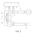
Fig. 2 is schematic diagram showing an engine on which an exhaust sensor according to another embodiment of the invention is mounted; -
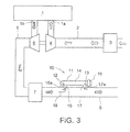
Fig. 3 is a schematic diagram showing an engine on which an exhaust sensor according to still another embodiment of the invention is mounted; -
Fig. 4 is a schematic diagram showing an engine on which an exhaust sensor according to still another embodiment of the invention is mounted; and -
Fig. 5 is a schematic diagram showing an engine on which an exhaust sensor according to still another embodiment of the invention is mounted. - Preferred embodiments of the invention will be described in detail with reference to the accompanying drawings.
- In
Fig. 1 , thereference numeral 1 denotes an engine (diesel engine in this embodiment), 2 denotes an intake pipe connected to anintake port 1a of theengine intake pipe engine 1 and arranged in theintake pipe 2 downstream of theair cleaner 3 in terms of flow of intake air, 5 denotes an exhaust pipe (tail pipe) connected to anexhaust port 1b of theengine turbo compressor 4 and arranged in theexhaust pipe exhaust pipe 5 downstream of theturbine 6 in terms of flow of the exhaust gas. The exhaustgas post-treatment apparatus 7 has, for example, a diesel particulate filter (DPF) for collecting particulate matters (PM) contained in the exhaust gas. - The
exhaust sensor 10 according to this embodiment is a sensor which is mounted on a vehicle and designed on the assumption that the vehicle has an on-board diagnostics (OBD) function. Theexhaust sensor 10 is a PM sensor which electrically charges air supplied thereto and detects an emission of particulate matters (PM) based on a variation in electrical charge. - The
exhaust sensor 10 according to this embodiment has a cylindrical (bottomed cylindrical or sheath-shaped)sensor body 11 arranged outside of theexhaust pipe 5 of theengine 1, agas inlet 12 formed at one end of thesensor body 11, agas outlet 13 formed at the other end of thesensor body 11, anozzle 14 housed within thesensor body 11 and ejecting air from the front end thereof, an electrode (not shown) for electrically charging air, and acover 15 for closing the other end of thesensor body 11. - In this embodiment, the
sensor body 11 and thenozzle 14 are arranged concentrically with each other. Although not shown in the drawings, an air compressor is connected to the base end of thenozzle 14 so that air is supplied to thenozzle 14 by this air compressor. - Further, in this embodiment, the
gas inlet 12 formed in thesensor body 11 communicates with theexhaust pipe 5 through anintroduction pipe 16, and thegas outlet 13 formed in thesensor body 11 communicates, through areturn pipe 17, with theexhaust pipe 5 on the downstream side of acommunication portion 16a of theintroduction pipe 16 in terms of flow of the exhaust gas. - In the embodiment, more particularly, one end of the introduction pipe 16 (an exhaust gas introduction portion, or the
communication portion 16a of theintroduction pipe 16 to the exhaust pipe 5) is connected to theexhaust pipe 5 on the downstream side of the exhaustgas post-treatment apparatus 7 in terms of flow of the exhaust gas, and the other end of theintroduction pipe 16 is connected to the sensor body 11 (the gas inlet 12). One end of thereturn pipe 17 is connected to the sensor body 11 (the gas outlet 13), and the other end of the return pipe 17 (an exhaust gas return portion, or thecommunication portion 17a of thereturn pipe 17 to the exhaust pipe 5) is connected to theexhaust pipe 5 on the downstream side of thecommunication portion 16a of theintroduction pipe 16 in terms of flow of the exhaust gas. - Operation of the embodiment will be described below.
- In this embodiment, the
sensor body 11 of theexhaust sensor 10 is arranged outside of theexhaust pipe 5 of theengine 1. Therefore, the exhaust sensor 10 (the sensor body 11) will not inhibit flow of the exhaust gas within theexhaust pipe 5. Since flow of the exhaust gas within theexhaust pipe 5 is not inhibited by theexhaust sensor 10, the attachment of theexhaust sensor 10 will not cause increase in back pressure of theengine 1, and hence the fuel economy of theengine 1 is not deteriorated. - In this embodiment, the
gas inlet 12 communicates with theexhaust pipe 5 through theintroduction pipe 16, while thegas outlet 13 communicates, through thereturn pipe 17, with theexhaust pipe 5 on the downstream side of thecommunication portion 16a of theintroduction pipe 16 in terms of flow of the exhaust gas. Therefore, the exhaust gas is discharged from thegas outlet 13 after being introduced into the inside of thesensor body 11 through thegas inlet 12, and then is allowed to return smoothly into the inside of theexhaust pipe 5 by a pressure difference between thecommunication portion 16a of theintroduction pipe 16 and thecommunication portion 17a of thereturn pipe 17. - In the conventional exhaust sensor shown in
Fig. 1 of Patent Document 1 (W02009/109688 ), the exhaust sensor which is arranged within the exhaust pipe inhibits flow of the exhaust gas. In the exhaust sensor shown inFig. 3 ofPatent Document 1, an electrode (29) and an ion trap (9) are arranged in an axial direction instead of on a concentric circle. Consequently, the size of the exhaust sensor is increased. According to the invention, the exhaust sensor (of the type corresponding to the one shown inFig. 1 of Patent Document 1) having an electrode (29) and an ion trap (9) arranged on a concentric circle is arranged outside of the exhaust pipe. - Although the invention has been described in its preferred form, it is understood that the invention is not limited to the embodiment described above, and various modifications and variations are possible.
- For example, in the embodiment described above, the exhaust gas introduction portion (the
communication portion 16a of theintroduction pipe 16 to the exhaust pipe 5) and the exhaust gas return portion (thecommunication portion 17a of thereturn pipe 17 to the exhaust pipe 5) are arranged in theexhaust pipe 5 on the downstream side of the exhaustgas post-treatment apparatus 7 in terms of flow of the exhaust gas. However, depending on characteristics of theexhaust sensor 10, as shown inFig. 2 , the exhaust gas introduction portion (thecommunication portion 16a of theintroduction pipe 16 to the exhaust pipe 5) and the exhaust gas return portion (thecommunication portion 17a of thereturn pipe 17 to the exhaust pipe 5) can be arranged in theexhaust pipe 5 on the upstream side of the exhaustgas post-treatment apparatus 7 in terms of flow of the exhaust gas. - In order to enable efficient introduction and discharge of the exhaust gas into and from the inside of the
sensor body 11, aguide 18 may be provided in the exhaust gas introduction portion (thecommunication portion 16a of theintroduction pipe 16 to the exhaust pipe 5) as shown inFig. 3 . - Further, in order to enable efficient introduction and discharge of the exhaust gas into and from the inside of the
sensor body 11, the exhaust gas return portion (thecommunication portion 17a of thereturn pipe 17 to the exhaust pipe 5) may be arranged at a position where a pressure difference with the exhaust gas introduction portion (thecommunication portion 16a of theintroduction pipe 16 to the exhaust pipe 5) is greater. For an example, as shown inFig. 4 , the exhaust gas introduction portion (thecommunication portion 16a of theintroduction pipe 16 to the exhaust pipe 5) may be arranged in theexhaust pipe 5 upstream of the exhaustgas post-treatment apparatus 7 in terms of flow of the exhaust gas, and the exhaust gas return portion (thecommunication portion 17a of thereturn pipe 17 to the exhaust pipe 5) may be arranged in theexhaust pipe 5 on the downstream side of the exhaustgas post-treatment apparatus 7 in terms of flow of the exhaust gas. - Further, as shown in
Fig. 5 , a valve (open/close valve) 19 may be provided in either one or both of theintroduction pipe 16 and the return pipe 17 (more particularly, in either one or both of thecommunication portion 16a of theintroduction pipe 16 and thecommunication portion 17a of the return pipe 17), so that the exhaust gas can be introduced into the inside of the exhaust sensor 10 (the inside of the sensor body 11) only when the exhaust gas is required for sensing. In the example shown inFig. 5 , thevalve 19 is provided in each of theintroduction pipe 16 and thereturn pipe 17. - The
exhaust sensor 10 is not limited to a PM sensor, but may be any other sensor for measuring exhaust gas components other than PM. -
- 1.
- Engine
- 2.
- Intake pipe
- 3.
- Air cleaner
- 4.
- Turbo compressor
- 5.
- Exhaust pipe (tail pipe)
- 6.
- Turbine
- 7.
- Exhaust gas post-treatment apparatus
- 10.
- Exhaust sensor
- 11.
- Sensor body
- 12.
- Gas inlet
- 13.
- Gas outlet
- 16.
- Introduction pipe
- 16a.
- Introduction pipe communication portion
- 17.
- Return pipe
- 17a.
- Return pipe communication portion
- 18.
- Guide
- 19.
- Open/close valve (valve)
Claims (7)
- An exhaust sensor for measuring exhaust gas components, comprising:a cylindrical sensor body arranged outside of an exhaust pipe of an engine;a gas inlet formed at one end of the sensor body; anda gas outlet formed at the other end of the sensor body,wherein:the gas inlet communicates with the exhaust pipe through an introduction pipe, while the gas outlet communicates, through a return pipe, with the exhaust pipe on the downstream side of a communication portion of the introduction pipe in terms of flow of the exhaust gas; andthe exhaust sensor is configured such that the exhaust gas is introduced into the sensor body through the gas inlet and then discharged from the sensor body through the gas outlet by a pressure difference between the communication portion of the introduction pipe and a communication portion of the return pipe.
- The exhaust sensor according to claim 1, wherein an open/close valve is provided in either one or both of the introduction pipe and the return pipe.
- The exhaust sensor according to claim 1 or 2, wherein a turbine is provided in the exhaust pipe, and the introduction pipe and the return pipe are connected to the exhaust pipe on the downstream side of the turbine in terms of flow of the exhaust gas.
- The exhaust sensor according to claim 3, wherein an exhaust gas post-treatment apparatus is provided in the exhaust pipe on the downstream side of the turbine in terms of flow of the exhaust gas, and the introduction pipe and the return pipe are connected to the exhaust pipe on the downstream side of the exhaust gas post-treatment apparatus in terms of flow of the exhaust gas.
- The exhaust sensor according to claim 3, wherein an exhaust gas post-treatment apparatus is provided in the exhaust pipe on the downstream side of the turbine in terms of flow of the exhaust gas, and the introduction pipe and the return pipe are connected to the exhaust pipe on the upstream side of the exhaust gas post-treatment apparatus in terms of flow of the exhaust gas.
- The exhaust sensor according to claim 3, wherein an exhaust gas post-treatment apparatus is provided in the exhaust pipe on the downstream side of the turbine in terms of flow of the exhaust gas, and the introduction pipe is connected to the exhaust pipe on the upstream side of the exhaust gas post-treatment apparatus in terms of flow of the exhaust gas, while the return pipe is connected to the exhaust pipe on the downstream side of the exhaust gas post-treatment apparatus in terms of flow of the exhaust gas.
- The exhaust sensor according to any one of claims 1 to 6, wherein a guide is provided in the communication portion between the exhaust pipe and the introduction pipe for the purpose of efficient introduction of the exhaust gas into the sensor body.
Applications Claiming Priority (2)
| Application Number | Priority Date | Filing Date | Title |
|---|---|---|---|
| JP2010094340A JP2011226313A (en) | 2010-04-15 | 2010-04-15 | Exhaust gas sensor |
| PCT/JP2011/058994 WO2011129296A1 (en) | 2010-04-15 | 2011-04-11 | Exhaust sensor |
Publications (3)
| Publication Number | Publication Date |
|---|---|
| EP2559887A1 true EP2559887A1 (en) | 2013-02-20 |
| EP2559887A4 EP2559887A4 (en) | 2014-10-29 |
| EP2559887B1 EP2559887B1 (en) | 2018-09-05 |
Family
ID=44798669
Family Applications (1)
| Application Number | Title | Priority Date | Filing Date |
|---|---|---|---|
| EP11768817.6A Not-in-force EP2559887B1 (en) | 2010-04-15 | 2011-04-11 | Exhaust sensor |
Country Status (5)
| Country | Link |
|---|---|
| US (1) | US9212592B2 (en) |
| EP (1) | EP2559887B1 (en) |
| JP (1) | JP2011226313A (en) |
| CN (1) | CN102844553B (en) |
| WO (1) | WO2011129296A1 (en) |
Cited By (3)
| Publication number | Priority date | Publication date | Assignee | Title |
|---|---|---|---|---|
| DE102012213161A1 (en) * | 2012-07-26 | 2014-01-30 | Bosch Mahle Turbo Systems Gmbh & Co. Kg | Turbine for an internal combustion engine |
| EP3048278A1 (en) * | 2015-01-26 | 2016-07-27 | Bosal Emission Control Systems NV | Device for the diagnosis of the operability of a particle filter for an exhaust gas stream of an internal combustion engine |
| EP2708610B1 (en) | 2011-05-12 | 2017-09-27 | JFE Steel Corporation | Vehicle collision energy absorbing member having high collision energy absorbing power, and method for manufacturing same |
Families Citing this family (11)
| Publication number | Priority date | Publication date | Assignee | Title |
|---|---|---|---|---|
| US9399943B1 (en) | 2015-05-04 | 2016-07-26 | Ford Global Technologies, Llc | System and method for detecting particulate filter leakage |
| US9551259B1 (en) * | 2015-08-26 | 2017-01-24 | Ford Global Technologies, Llc | Method and system for diesel particulate filter diagnostics |
| US9551262B1 (en) * | 2015-10-13 | 2017-01-24 | Ford Global Technologies, Llc | Method and system for particulate filter leakage detection |
| US9645068B2 (en) | 2015-10-13 | 2017-05-09 | Ford Global Technologies, Llc | Method and system for particulate filter leakage detection |
| US9689295B1 (en) | 2016-01-29 | 2017-06-27 | Ford Global Technologies, Llc | Method and system for exhaust gas heat recovery |
| US9957871B2 (en) | 2016-01-29 | 2018-05-01 | Ford Global Technologies, Llc | Exhaust heat recovery and hydrocarbon trapping |
| US9845750B2 (en) | 2016-01-29 | 2017-12-19 | Ford Global Technologies, Llc | Method and system for exhaust gas heat recovery |
| US10107213B2 (en) * | 2016-12-01 | 2018-10-23 | Ford Global Technologies, Llc | Method and system for exhaust gas recirculation and heat recovery |
| US10378417B2 (en) | 2017-04-04 | 2019-08-13 | Ford Global Technologies, Llc | Method and system for exhaust particulate matter sensing |
| JP7017136B2 (en) * | 2018-10-24 | 2022-02-08 | 株式会社デンソー | Vehicle dust measuring device |
| DE102021122492A1 (en) * | 2021-08-31 | 2023-03-02 | Hug Engineering Ag | exhaust system |
Family Cites Families (20)
| Publication number | Priority date | Publication date | Assignee | Title |
|---|---|---|---|---|
| US3607084A (en) * | 1968-12-02 | 1971-09-21 | Sun Electric Corp | Combustible gas measurement |
| US3766715A (en) * | 1971-05-26 | 1973-10-23 | Erdco Eng Corp | Method and apparatus for combustible gas detection in dirt laden atmosphere |
| JPS5213584B2 (en) * | 1973-07-06 | 1977-04-15 | ||
| IE43146B1 (en) | 1975-07-22 | 1980-12-31 | Cpc International Inc | Starch based corrugating adhesives and methods for their preparation |
| JPS6396218A (en) | 1986-10-11 | 1988-04-27 | Kawasaki Steel Corp | Production of extremely low iron loss grain oriented silicon steel sheet |
| JPH0234416Y2 (en) * | 1986-12-15 | 1990-09-17 | ||
| JPH0621552B2 (en) * | 1989-02-13 | 1994-03-23 | いすゞ自動車株式会社 | Reburner for particulate trap |
| JPH031235U (en) * | 1989-05-29 | 1991-01-09 | ||
| JPH0694829B2 (en) * | 1989-08-16 | 1994-11-24 | 大阪瓦斯株式会社 | Test O ▲ Lower 2 ▼ Sensor protection device |
| US5711148A (en) | 1994-05-06 | 1998-01-27 | Sanshin Kogyo Kabushiki Kaisha | Sensor arrangement for engine control system |
| US5836155A (en) | 1994-05-06 | 1998-11-17 | Sanshin Kogyo Kabushiki Kaisha | Sensor arrangement for engine control system |
| JP3585525B2 (en) * | 1994-05-06 | 2004-11-04 | ヤマハマリン株式会社 | Engine air-fuel ratio control device |
| JP2000018020A (en) * | 1998-04-30 | 2000-01-18 | Nippon Soken Inc | Black smoke emission reduction system for internal combustion engine |
| US7258772B2 (en) * | 2002-05-17 | 2007-08-21 | Hitachi, Ltd. | Oxygen sensor and method of manufacturing same |
| JP4006733B2 (en) * | 2002-12-16 | 2007-11-14 | 学校法人東海大学 | Method and apparatus for measuring mass concentration of soot aggregate in combustion exhaust |
| US7739898B2 (en) * | 2005-06-24 | 2010-06-22 | General Electric Company | System and method for operating an exhaust gas sensor system |
| JP4924221B2 (en) * | 2007-06-08 | 2012-04-25 | トヨタ自動車株式会社 | Exhaust gas purification system for internal combustion engine |
| JP4430704B2 (en) * | 2007-10-01 | 2010-03-10 | 本田技研工業株式会社 | Exhaust gas purification device for internal combustion engine |
| FI20080182A0 (en) * | 2008-03-04 | 2008-03-04 | Navaro 245 Oy | Measurement method and apparatus |
| EP3137744A1 (en) | 2009-09-15 | 2017-03-08 | Zidat, Saïd | Device for diagnosing a particle filter |
-
2010
- 2010-04-15 JP JP2010094340A patent/JP2011226313A/en active Pending
-
2011
- 2011-04-11 EP EP11768817.6A patent/EP2559887B1/en not_active Not-in-force
- 2011-04-11 US US13/640,938 patent/US9212592B2/en active Active
- 2011-04-11 WO PCT/JP2011/058994 patent/WO2011129296A1/en not_active Ceased
- 2011-04-11 CN CN201180018805.3A patent/CN102844553B/en active Active
Cited By (5)
| Publication number | Priority date | Publication date | Assignee | Title |
|---|---|---|---|---|
| EP2708610B1 (en) | 2011-05-12 | 2017-09-27 | JFE Steel Corporation | Vehicle collision energy absorbing member having high collision energy absorbing power, and method for manufacturing same |
| DE102012213161A1 (en) * | 2012-07-26 | 2014-01-30 | Bosch Mahle Turbo Systems Gmbh & Co. Kg | Turbine for an internal combustion engine |
| US9181874B2 (en) | 2012-07-26 | 2015-11-10 | Bosch Mahle Turbo Systems Gmbh & Co. Kg | Turbine for an internal combustion engine |
| DE102012213161B4 (en) | 2012-07-26 | 2019-07-25 | BMTS Technology GmbH & Co. KG | Turbine for an internal combustion engine |
| EP3048278A1 (en) * | 2015-01-26 | 2016-07-27 | Bosal Emission Control Systems NV | Device for the diagnosis of the operability of a particle filter for an exhaust gas stream of an internal combustion engine |
Also Published As
| Publication number | Publication date |
|---|---|
| EP2559887A4 (en) | 2014-10-29 |
| CN102844553A (en) | 2012-12-26 |
| JP2011226313A (en) | 2011-11-10 |
| US9212592B2 (en) | 2015-12-15 |
| WO2011129296A1 (en) | 2011-10-20 |
| EP2559887B1 (en) | 2018-09-05 |
| US20130031967A1 (en) | 2013-02-07 |
| CN102844553B (en) | 2015-11-25 |
Similar Documents
| Publication | Publication Date | Title |
|---|---|---|
| EP2559887B1 (en) | Exhaust sensor | |
| CN103808782B (en) | Operation is used for the method and apparatus to determine the sensor of exhaust gas constituents of motor vehicle | |
| EP3084189B1 (en) | Control system for internal combustion engine | |
| JP4430704B2 (en) | Exhaust gas purification device for internal combustion engine | |
| CN103946511B (en) | engine with supercharger | |
| EP1745199B1 (en) | Exhaust gas control apparatus | |
| US9181854B2 (en) | Turbocharger | |
| US20120186228A1 (en) | Particle filter and method for the purification of an exhaust-gas flow | |
| EP2559989B1 (en) | Exhaust sensor alignment structure | |
| JP5736662B2 (en) | Exhaust sensor | |
| US10619545B2 (en) | System of forcibly regenerating gasoline particulate filter | |
| JP4844569B2 (en) | Internal combustion engine supercharging system | |
| EP3056699B1 (en) | Exhaust purification system | |
| US20150377194A1 (en) | Internal-combustion-engine supercharger | |
| CN209011913U (en) | Gasoline engine particle capture device | |
| CN112746884A (en) | Exhaust system of engine | |
| CN104343562B (en) | Method for operating an internal combustion engine | |
| EP4560124A1 (en) | Control device and control method | |
| JP4577015B2 (en) | Exhaust gas purification device for internal combustion engine | |
| CN110761891A (en) | Engine system | |
| JP4140387B2 (en) | Exhaust gas purification device for internal combustion engine | |
| US20120055155A1 (en) | Internal combustion engine | |
| CN112746880A (en) | Exhaust system of engine | |
| JP2021032143A (en) | Blow-by gas treatment device |
Legal Events
| Date | Code | Title | Description |
|---|---|---|---|
| PUAI | Public reference made under article 153(3) epc to a published international application that has entered the european phase |
Free format text: ORIGINAL CODE: 0009012 |
|
| 17P | Request for examination filed |
Effective date: 20121113 |
|
| AK | Designated contracting states |
Kind code of ref document: A1 Designated state(s): AL AT BE BG CH CY CZ DE DK EE ES FI FR GB GR HR HU IE IS IT LI LT LU LV MC MK MT NL NO PL PT RO RS SE SI SK SM TR |
|
| DAX | Request for extension of the european patent (deleted) | ||
| A4 | Supplementary search report drawn up and despatched |
Effective date: 20140926 |
|
| RIC1 | Information provided on ipc code assigned before grant |
Ipc: F02D 35/00 20060101AFI20140922BHEP Ipc: F01N 13/00 20100101ALI20140922BHEP |
|
| 17Q | First examination report despatched |
Effective date: 20160708 |
|
| STAA | Information on the status of an ep patent application or granted ep patent |
Free format text: STATUS: EXAMINATION IS IN PROGRESS |
|
| GRAP | Despatch of communication of intention to grant a patent |
Free format text: ORIGINAL CODE: EPIDOSNIGR1 |
|
| STAA | Information on the status of an ep patent application or granted ep patent |
Free format text: STATUS: GRANT OF PATENT IS INTENDED |
|
| INTG | Intention to grant announced |
Effective date: 20180316 |
|
| GRAS | Grant fee paid |
Free format text: ORIGINAL CODE: EPIDOSNIGR3 |
|
| GRAA | (expected) grant |
Free format text: ORIGINAL CODE: 0009210 |
|
| STAA | Information on the status of an ep patent application or granted ep patent |
Free format text: STATUS: THE PATENT HAS BEEN GRANTED |
|
| AK | Designated contracting states |
Kind code of ref document: B1 Designated state(s): AL AT BE BG CH CY CZ DE DK EE ES FI FR GB GR HR HU IE IS IT LI LT LU LV MC MK MT NL NO PL PT RO RS SE SI SK SM TR |
|
| REG | Reference to a national code |
Ref country code: GB Ref legal event code: FG4D |
|
| REG | Reference to a national code |
Ref country code: CH Ref legal event code: EP |
|
| REG | Reference to a national code |
Ref country code: AT Ref legal event code: REF Ref document number: 1038085 Country of ref document: AT Kind code of ref document: T Effective date: 20180915 |
|
| REG | Reference to a national code |
Ref country code: IE Ref legal event code: FG4D |
|
| REG | Reference to a national code |
Ref country code: DE Ref legal event code: R096 Ref document number: 602011051798 Country of ref document: DE |
|
| REG | Reference to a national code |
Ref country code: NL Ref legal event code: MP Effective date: 20180905 |
|
| REG | Reference to a national code |
Ref country code: LT Ref legal event code: MG4D |
|
| REG | Reference to a national code |
Ref country code: SE Ref legal event code: TRGR |
|
| PG25 | Lapsed in a contracting state [announced via postgrant information from national office to epo] |
Ref country code: FI Free format text: LAPSE BECAUSE OF FAILURE TO SUBMIT A TRANSLATION OF THE DESCRIPTION OR TO PAY THE FEE WITHIN THE PRESCRIBED TIME-LIMIT Effective date: 20180905 Ref country code: LT Free format text: LAPSE BECAUSE OF FAILURE TO SUBMIT A TRANSLATION OF THE DESCRIPTION OR TO PAY THE FEE WITHIN THE PRESCRIBED TIME-LIMIT Effective date: 20180905 Ref country code: GR Free format text: LAPSE BECAUSE OF FAILURE TO SUBMIT A TRANSLATION OF THE DESCRIPTION OR TO PAY THE FEE WITHIN THE PRESCRIBED TIME-LIMIT Effective date: 20181206 Ref country code: BG Free format text: LAPSE BECAUSE OF FAILURE TO SUBMIT A TRANSLATION OF THE DESCRIPTION OR TO PAY THE FEE WITHIN THE PRESCRIBED TIME-LIMIT Effective date: 20181205 Ref country code: RS Free format text: LAPSE BECAUSE OF FAILURE TO SUBMIT A TRANSLATION OF THE DESCRIPTION OR TO PAY THE FEE WITHIN THE PRESCRIBED TIME-LIMIT Effective date: 20180905 Ref country code: NO Free format text: LAPSE BECAUSE OF FAILURE TO SUBMIT A TRANSLATION OF THE DESCRIPTION OR TO PAY THE FEE WITHIN THE PRESCRIBED TIME-LIMIT Effective date: 20181205 |
|
| REG | Reference to a national code |
Ref country code: AT Ref legal event code: MK05 Ref document number: 1038085 Country of ref document: AT Kind code of ref document: T Effective date: 20180905 |
|
| PG25 | Lapsed in a contracting state [announced via postgrant information from national office to epo] |
Ref country code: HR Free format text: LAPSE BECAUSE OF FAILURE TO SUBMIT A TRANSLATION OF THE DESCRIPTION OR TO PAY THE FEE WITHIN THE PRESCRIBED TIME-LIMIT Effective date: 20180905 Ref country code: AL Free format text: LAPSE BECAUSE OF FAILURE TO SUBMIT A TRANSLATION OF THE DESCRIPTION OR TO PAY THE FEE WITHIN THE PRESCRIBED TIME-LIMIT Effective date: 20180905 Ref country code: LV Free format text: LAPSE BECAUSE OF FAILURE TO SUBMIT A TRANSLATION OF THE DESCRIPTION OR TO PAY THE FEE WITHIN THE PRESCRIBED TIME-LIMIT Effective date: 20180905 |
|
| PG25 | Lapsed in a contracting state [announced via postgrant information from national office to epo] |
Ref country code: ES Free format text: LAPSE BECAUSE OF FAILURE TO SUBMIT A TRANSLATION OF THE DESCRIPTION OR TO PAY THE FEE WITHIN THE PRESCRIBED TIME-LIMIT Effective date: 20180905 Ref country code: CZ Free format text: LAPSE BECAUSE OF FAILURE TO SUBMIT A TRANSLATION OF THE DESCRIPTION OR TO PAY THE FEE WITHIN THE PRESCRIBED TIME-LIMIT Effective date: 20180905 Ref country code: IT Free format text: LAPSE BECAUSE OF FAILURE TO SUBMIT A TRANSLATION OF THE DESCRIPTION OR TO PAY THE FEE WITHIN THE PRESCRIBED TIME-LIMIT Effective date: 20180905 Ref country code: RO Free format text: LAPSE BECAUSE OF FAILURE TO SUBMIT A TRANSLATION OF THE DESCRIPTION OR TO PAY THE FEE WITHIN THE PRESCRIBED TIME-LIMIT Effective date: 20180905 Ref country code: EE Free format text: LAPSE BECAUSE OF FAILURE TO SUBMIT A TRANSLATION OF THE DESCRIPTION OR TO PAY THE FEE WITHIN THE PRESCRIBED TIME-LIMIT Effective date: 20180905 Ref country code: AT Free format text: LAPSE BECAUSE OF FAILURE TO SUBMIT A TRANSLATION OF THE DESCRIPTION OR TO PAY THE FEE WITHIN THE PRESCRIBED TIME-LIMIT Effective date: 20180905 Ref country code: NL Free format text: LAPSE BECAUSE OF FAILURE TO SUBMIT A TRANSLATION OF THE DESCRIPTION OR TO PAY THE FEE WITHIN THE PRESCRIBED TIME-LIMIT Effective date: 20180905 Ref country code: PL Free format text: LAPSE BECAUSE OF FAILURE TO SUBMIT A TRANSLATION OF THE DESCRIPTION OR TO PAY THE FEE WITHIN THE PRESCRIBED TIME-LIMIT Effective date: 20180905 Ref country code: IS Free format text: LAPSE BECAUSE OF FAILURE TO SUBMIT A TRANSLATION OF THE DESCRIPTION OR TO PAY THE FEE WITHIN THE PRESCRIBED TIME-LIMIT Effective date: 20190105 |
|
| PG25 | Lapsed in a contracting state [announced via postgrant information from national office to epo] |
Ref country code: PT Free format text: LAPSE BECAUSE OF FAILURE TO SUBMIT A TRANSLATION OF THE DESCRIPTION OR TO PAY THE FEE WITHIN THE PRESCRIBED TIME-LIMIT Effective date: 20190105 Ref country code: SK Free format text: LAPSE BECAUSE OF FAILURE TO SUBMIT A TRANSLATION OF THE DESCRIPTION OR TO PAY THE FEE WITHIN THE PRESCRIBED TIME-LIMIT Effective date: 20180905 Ref country code: SM Free format text: LAPSE BECAUSE OF FAILURE TO SUBMIT A TRANSLATION OF THE DESCRIPTION OR TO PAY THE FEE WITHIN THE PRESCRIBED TIME-LIMIT Effective date: 20180905 |
|
| REG | Reference to a national code |
Ref country code: DE Ref legal event code: R097 Ref document number: 602011051798 Country of ref document: DE |
|
| PLBE | No opposition filed within time limit |
Free format text: ORIGINAL CODE: 0009261 |
|
| STAA | Information on the status of an ep patent application or granted ep patent |
Free format text: STATUS: NO OPPOSITION FILED WITHIN TIME LIMIT |
|
| PG25 | Lapsed in a contracting state [announced via postgrant information from national office to epo] |
Ref country code: DK Free format text: LAPSE BECAUSE OF FAILURE TO SUBMIT A TRANSLATION OF THE DESCRIPTION OR TO PAY THE FEE WITHIN THE PRESCRIBED TIME-LIMIT Effective date: 20180905 |
|
| PGFP | Annual fee paid to national office [announced via postgrant information from national office to epo] |
Ref country code: DE Payment date: 20190529 Year of fee payment: 9 |
|
| 26N | No opposition filed |
Effective date: 20190606 |
|
| PG25 | Lapsed in a contracting state [announced via postgrant information from national office to epo] |
Ref country code: SI Free format text: LAPSE BECAUSE OF FAILURE TO SUBMIT A TRANSLATION OF THE DESCRIPTION OR TO PAY THE FEE WITHIN THE PRESCRIBED TIME-LIMIT Effective date: 20180905 |
|
| PGFP | Annual fee paid to national office [announced via postgrant information from national office to epo] |
Ref country code: SE Payment date: 20190425 Year of fee payment: 9 Ref country code: FR Payment date: 20190423 Year of fee payment: 9 |
|
| REG | Reference to a national code |
Ref country code: CH Ref legal event code: PL |
|
| REG | Reference to a national code |
Ref country code: BE Ref legal event code: MM Effective date: 20190430 |
|
| GBPC | Gb: european patent ceased through non-payment of renewal fee |
Effective date: 20190411 |
|
| PG25 | Lapsed in a contracting state [announced via postgrant information from national office to epo] |
Ref country code: LU Free format text: LAPSE BECAUSE OF NON-PAYMENT OF DUE FEES Effective date: 20190411 Ref country code: MC Free format text: LAPSE BECAUSE OF FAILURE TO SUBMIT A TRANSLATION OF THE DESCRIPTION OR TO PAY THE FEE WITHIN THE PRESCRIBED TIME-LIMIT Effective date: 20180905 |
|
| PG25 | Lapsed in a contracting state [announced via postgrant information from national office to epo] |
Ref country code: CH Free format text: LAPSE BECAUSE OF NON-PAYMENT OF DUE FEES Effective date: 20190430 Ref country code: GB Free format text: LAPSE BECAUSE OF NON-PAYMENT OF DUE FEES Effective date: 20190411 Ref country code: LI Free format text: LAPSE BECAUSE OF NON-PAYMENT OF DUE FEES Effective date: 20190430 |
|
| PG25 | Lapsed in a contracting state [announced via postgrant information from national office to epo] |
Ref country code: BE Free format text: LAPSE BECAUSE OF NON-PAYMENT OF DUE FEES Effective date: 20190430 |
|
| PG25 | Lapsed in a contracting state [announced via postgrant information from national office to epo] |
Ref country code: TR Free format text: LAPSE BECAUSE OF FAILURE TO SUBMIT A TRANSLATION OF THE DESCRIPTION OR TO PAY THE FEE WITHIN THE PRESCRIBED TIME-LIMIT Effective date: 20180905 |
|
| PG25 | Lapsed in a contracting state [announced via postgrant information from national office to epo] |
Ref country code: IE Free format text: LAPSE BECAUSE OF NON-PAYMENT OF DUE FEES Effective date: 20190411 |
|
| REG | Reference to a national code |
Ref country code: DE Ref legal event code: R119 Ref document number: 602011051798 Country of ref document: DE |
|
| PG25 | Lapsed in a contracting state [announced via postgrant information from national office to epo] |
Ref country code: FR Free format text: LAPSE BECAUSE OF NON-PAYMENT OF DUE FEES Effective date: 20200430 Ref country code: SE Free format text: LAPSE BECAUSE OF NON-PAYMENT OF DUE FEES Effective date: 20200412 Ref country code: DE Free format text: LAPSE BECAUSE OF NON-PAYMENT OF DUE FEES Effective date: 20201103 |
|
| PG25 | Lapsed in a contracting state [announced via postgrant information from national office to epo] |
Ref country code: CY Free format text: LAPSE BECAUSE OF FAILURE TO SUBMIT A TRANSLATION OF THE DESCRIPTION OR TO PAY THE FEE WITHIN THE PRESCRIBED TIME-LIMIT Effective date: 20180905 |
|
| PG25 | Lapsed in a contracting state [announced via postgrant information from national office to epo] |
Ref country code: HU Free format text: LAPSE BECAUSE OF FAILURE TO SUBMIT A TRANSLATION OF THE DESCRIPTION OR TO PAY THE FEE WITHIN THE PRESCRIBED TIME-LIMIT; INVALID AB INITIO Effective date: 20110411 Ref country code: MT Free format text: LAPSE BECAUSE OF FAILURE TO SUBMIT A TRANSLATION OF THE DESCRIPTION OR TO PAY THE FEE WITHIN THE PRESCRIBED TIME-LIMIT Effective date: 20180905 |
|
| PG25 | Lapsed in a contracting state [announced via postgrant information from national office to epo] |
Ref country code: MK Free format text: LAPSE BECAUSE OF FAILURE TO SUBMIT A TRANSLATION OF THE DESCRIPTION OR TO PAY THE FEE WITHIN THE PRESCRIBED TIME-LIMIT Effective date: 20180905 |