EP2559867A1 - Method for generating electrical energy with a combination power plant and combination power plant and device for carrying out the method - Google Patents
Method for generating electrical energy with a combination power plant and combination power plant and device for carrying out the method Download PDFInfo
- Publication number
- EP2559867A1 EP2559867A1 EP11178136A EP11178136A EP2559867A1 EP 2559867 A1 EP2559867 A1 EP 2559867A1 EP 11178136 A EP11178136 A EP 11178136A EP 11178136 A EP11178136 A EP 11178136A EP 2559867 A1 EP2559867 A1 EP 2559867A1
- Authority
- EP
- European Patent Office
- Prior art keywords
- turbine
- power plant
- water
- heat recovery
- exhaust gas
- Prior art date
- Legal status (The legal status is an assumption and is not a legal conclusion. Google has not performed a legal analysis and makes no representation as to the accuracy of the status listed.)
- Withdrawn
Links
Images
Classifications
-
- F—MECHANICAL ENGINEERING; LIGHTING; HEATING; WEAPONS; BLASTING
- F01—MACHINES OR ENGINES IN GENERAL; ENGINE PLANTS IN GENERAL; STEAM ENGINES
- F01K—STEAM ENGINE PLANTS; STEAM ACCUMULATORS; ENGINE PLANTS NOT OTHERWISE PROVIDED FOR; ENGINES USING SPECIAL WORKING FLUIDS OR CYCLES
- F01K23/00—Plants characterised by more than one engine delivering power external to the plant, the engines being driven by different fluids
- F01K23/02—Plants characterised by more than one engine delivering power external to the plant, the engines being driven by different fluids the engine cycles being thermally coupled
- F01K23/06—Plants characterised by more than one engine delivering power external to the plant, the engines being driven by different fluids the engine cycles being thermally coupled combustion heat from one cycle heating the fluid in another cycle
- F01K23/10—Plants characterised by more than one engine delivering power external to the plant, the engines being driven by different fluids the engine cycles being thermally coupled combustion heat from one cycle heating the fluid in another cycle with exhaust fluid of one cycle heating the fluid in another cycle
-
- F—MECHANICAL ENGINEERING; LIGHTING; HEATING; WEAPONS; BLASTING
- F01—MACHINES OR ENGINES IN GENERAL; ENGINE PLANTS IN GENERAL; STEAM ENGINES
- F01K—STEAM ENGINE PLANTS; STEAM ACCUMULATORS; ENGINE PLANTS NOT OTHERWISE PROVIDED FOR; ENGINES USING SPECIAL WORKING FLUIDS OR CYCLES
- F01K23/00—Plants characterised by more than one engine delivering power external to the plant, the engines being driven by different fluids
- F01K23/12—Plants characterised by more than one engine delivering power external to the plant, the engines being driven by different fluids the engines being mechanically coupled
- F01K23/16—Plants characterised by more than one engine delivering power external to the plant, the engines being driven by different fluids the engines being mechanically coupled all the engines being turbines
-
- F—MECHANICAL ENGINEERING; LIGHTING; HEATING; WEAPONS; BLASTING
- F01—MACHINES OR ENGINES IN GENERAL; ENGINE PLANTS IN GENERAL; STEAM ENGINES
- F01K—STEAM ENGINE PLANTS; STEAM ACCUMULATORS; ENGINE PLANTS NOT OTHERWISE PROVIDED FOR; ENGINES USING SPECIAL WORKING FLUIDS OR CYCLES
- F01K25/00—Plants or engines characterised by use of special working fluids, not otherwise provided for; Plants operating in closed cycles and not otherwise provided for
- F01K25/08—Plants or engines characterised by use of special working fluids, not otherwise provided for; Plants operating in closed cycles and not otherwise provided for using special vapours
- F01K25/10—Plants or engines characterised by use of special working fluids, not otherwise provided for; Plants operating in closed cycles and not otherwise provided for using special vapours the vapours being cold, e.g. ammonia, carbon dioxide, ether
- F01K25/103—Carbon dioxide
-
- Y—GENERAL TAGGING OF NEW TECHNOLOGICAL DEVELOPMENTS; GENERAL TAGGING OF CROSS-SECTIONAL TECHNOLOGIES SPANNING OVER SEVERAL SECTIONS OF THE IPC; TECHNICAL SUBJECTS COVERED BY FORMER USPC CROSS-REFERENCE ART COLLECTIONS [XRACs] AND DIGESTS
- Y02—TECHNOLOGIES OR APPLICATIONS FOR MITIGATION OR ADAPTATION AGAINST CLIMATE CHANGE
- Y02E—REDUCTION OF GREENHOUSE GAS [GHG] EMISSIONS, RELATED TO ENERGY GENERATION, TRANSMISSION OR DISTRIBUTION
- Y02E20/00—Combustion technologies with mitigation potential
- Y02E20/16—Combined cycle power plant [CCPP], or combined cycle gas turbine [CCGT]
Landscapes
- Engineering & Computer Science (AREA)
- Chemical & Material Sciences (AREA)
- Combustion & Propulsion (AREA)
- Mechanical Engineering (AREA)
- General Engineering & Computer Science (AREA)
- Chemical Kinetics & Catalysis (AREA)
- Engine Equipment That Uses Special Cycles (AREA)
Abstract
Description
Die vorliegende Erfindung bezieht sich auf das Gebiet der Kraftwerkstechnik. Sie betrifft ein Verfahren zum Erzeugen von elektrischer Energie gemäss dem Oberbegriff des Anspruchs 1. Sie betrifft weiterhin ein Kombikraftwerk zur Durchführung des Verfahrens.The present invention relates to the field of power plant technology. It relates to a method for generating electrical energy according to the preamble of
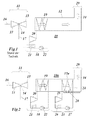
Die vorliegende Erfindung geht aus von einem Kombikraftwerk nach dem Stand der Technik, wie es schematisch in
Das Heissgas aus der Brennkammer 14 wird in der nachfolgenden Turbine 15 unter Arbeitsleistung entspannt (bei der sequenziellen Verbrennung ist dies entsprechend ein zweistufiger Vorgang). Das Abgas 34 aus der Turbine 15 wird durch einen nachgeschalteten Abhitzedampferzeuger 12 geschickt und über einen Abgaskamin 29 nach aussen abgegeben. Im Abhitzedampferzeuger 12 ist ein von dem Abgas 34 umströmter Verdampfer 19 angeordnet, der Teil eines geschlossenen Wasser-Dampf-Kreislaufs 18 ist. In dem Verdampfer 19 wird das von einer Speisewasserpumpe 22 herangeführte Wasser verdampft, der Dampf treibt eine Dampfturbine 20, wird dann in einem Kondensator 21 wieder kondensiert und zum Eingang der Speisewasserpumpe 21 zurückgeführt. Der Verdampfer, der auf die Figuren gezeichnet ist, ist eine vereinfachte Darstellung. In Tat und Wahrheit handelt es sich um einen Dreidruck-Reheat Kreislauf mit drein ineinander verschachtelten Verdampfern und drein entsprechenden Stufen der Dampfturbine.The hot gas from the
Um den Wirkungsgrad eines solchen Kombikraftwerkes zu verbessern, wird üblicherweise versucht, die Einlasstemperaturen für die Turbinen zu erhöhen. Dies setzt jedoch aufwändige und umfangreiche Verbesserungen bei den verwendeten Werkstoffen beziehungsweise Kühlprozessen voraus. Es ist deshalb wünschenswert, den Wirkungsgrad einer solchen Anlage auf andere, einfachere Weise zu verbessern.In order to improve the efficiency of such a combined cycle power plant, it is usually tried to increase the inlet temperatures for the turbines. However, this requires complex and extensive improvements in the materials used or cooling processes. It is therefore desirable to improve the efficiency of such a system in a different, simpler way.
Aus dem Stand der Technik ist es bekannt, einen Verdichter, wie er in einer Gasturbine eingesetzt wird, durch eine Verdampfungskühlung zu kühlen. Entsprechende Kühlprozesse, die auf dem Einspritzen von Wasser in verschiedenen Verdichterstufen basieren, sind beispielsweise aus der Druckschrift
Es ist weiterhin aus dem Stand der Technik bekannt, Niedertemperatur-Abwärme bestimmter Maschinen durch Niedertemperaturkreisläufe wie zum Beispiel ORC-Prozesse (Organic Rankine Cycle) nutzbar zu machen (siehe z.B. die
Es ist eine Aufgabe der Erfindung, ein gattungsgemässes Verfahren zum Erzeugen von elektrischer Energie mittels eines Kombikraftwerkes so weiterzuentwickeln, dass auf einfache Weise und mit vergleichsweise geringem Aufwand der Wirkungsgrad verbessert werden kann.It is an object of the invention to develop a generic method for generating electrical energy by means of a combined cycle power plant so that in a simple manner and with relatively little effort, the efficiency can be improved.
Es ist weiterhin eine Aufgabe der Erfindung, ein Kombikraftwerk zur Durchführung eines solchen Verfahrens anzugeben.It is a further object of the invention to provide a combined cycle power plant for carrying out such a method.
Diese und andere Aufgaben werden durch die Gesamtheit der Merkmale der Ansprüche 1 und 10 gelöst.These and other objects are achieved by the entirety of the features of
Die Erfindung geht aus von einem Verfahren zum Erzeugen von elektrischer Energie mittels eines Kombikraftwerkes, bei welchem Verfahren in einer Gasturbine durch Verbrennen eines Brennstoffs mittels in einem Verdichter verdichteter Luft ein Heissgas erzeugt und in einer nachfolgenden Turbine unter Arbeitsleistung entspannt wird und das Abgas aus der Turbine in einem nachgeschalteten Abhitzedampferzeuger zur Erzeugung von Dampf in einem mit einer Dampfturbine ausgerüsteten Wasser-Dampf-Kreislauf eingesetzt wird.The invention is based on a method for generating electrical energy by means of a combined cycle power plant, in which method in a gas turbine by burning a fuel by means of compressed air in a compressor hot gas is generated and expanded in a subsequent turbine under working performance and the exhaust gas from the turbine is used in a downstream heat recovery steam generator for generating steam in a equipped with a steam turbine water-steam cycle.
Sie zeichnet sich dadurch aus, dass im Abgas Wasserdampf enthalten ist und die im Wasserdampf enthaltene latente Wärme zusätzlich zur Energieerzeugung herangezogen wird.It is characterized by the fact that water vapor is contained in the exhaust gas and the latent heat contained in the water vapor is additionally used for generating energy.
Eine Ausgestaltung des erfindungsgemässen Verfahrens ist dadurch gekennzeichnet, dass die im Wasserdampf des Abgases enthaltene latente Wärme dem Wasserdampf durch einen Niedertemperaturkreislauf entzogen wird.An embodiment of the method according to the invention is characterized in that the latent heat contained in the water vapor of the exhaust gas is withdrawn from the water vapor by a low-temperature circuit.
Insbesondere umfasst der Niedertemperaturkreislauf eine Turbine, einen Kondensator, eine Pumpe und einen Verdampfer, wobei der Verdampfer von dem Abgas umströmt wird, nachdem das Abgas zur Erzeugung von Dampf in einem mit einer Dampfturbine ausgerüsteten Wasser-Dampf-Kreislauf eingesetzt worden ist.In particular, the low-temperature circuit comprises a turbine, a condenser, a pump and an evaporator, wherein the exhaust gas is flowed around by the exhaust gas after the exhaust gas has been used to generate steam in a water-steam cycle equipped with a steam turbine.
Eine andere Ausgestaltung des Verfahrens nach der Erfindung ist dadurch gekennzeichnet, dass das bei der Verwendung der latenten Wärme entstehende Wasser gesammelt und einer weiteren Verwendung zugeführt wird.Another embodiment of the method according to the invention is characterized in that the water resulting from the use of the latent heat is collected and supplied for further use.
Insbesondere wird das gesammelte Wasser zur Verdampfungskühlung in den Verdichter der Gasturbine eingespritzt.In particular, the collected water is injected into the compressor of the gas turbine for evaporative cooling.
Besonders vorteilhaft ist es dabei, wenn das gesammelte Wasser vor dem Einspritzen in den Verdichter durch das Abgas im Abhitzedampferzeuger vorgewärmt wird.It is particularly advantageous if the collected water is preheated before being injected into the compressor by the exhaust gas in the heat recovery steam generator.
Eine weitere Ausgestaltung des Verfahrens nach der Erfindung zeichnet sich dadurch aus, dass ein Teil des Abgases am Ausgang des Abhitzedampferzeugers abgezweigt und zum Eingang der Gasturbine zurückgeführt wird.A further embodiment of the method according to the invention is characterized in that a part of the exhaust gas is branched off at the outlet of the heat recovery steam generator and returned to the input of the gas turbine.
Eine wieder andere Ausgestaltung ist dadurch gekennzeichnet, dass die im Verdichter der Gasturbine verdichtete Luft vor dem Verbrennen des Brennstoffs im Abhitzedampferzeuger vorgewärmt wird.Yet another embodiment is characterized in that the air compressed in the compressor of the gas turbine is preheated before the combustion of the fuel in the heat recovery steam generator.
Gemäss einer weiteren Ausgestaltung wird eine Gasturbine mit sequenzieller Verbrennung verwendet.According to a further embodiment, a gas turbine with sequential combustion is used.
Eine andere Ausgestaltung zeichnet sich dadurch aus, dass als Arbeitsmittel im Niedertemperaturkreislauf CO2 verwendet wird.Another embodiment is characterized in that CO2 is used as the working medium in the low-temperature cycle.
Das erfindungsgemässe Kombikraftwerk zur Durchführung des Verfahrens nach der Erfindung umfasst eine Gasturbine, einen der Gasturbine nachgeschalteten Abhitzedampferzeuger sowie einen Wasser-Dampf-Kreislauf mit einem im Abhitzedampferzeuger angeordneten ersten Verdampfer, einer Dampfturbine, einem Kondensator und einer Speisewasserpumpe. Es ist dadurch gekennzeichnet, dass zum Nutzbarmachen der latenten Wärme, die im Wasserdampf des durch den Abhitzedampferzeuger strömenden Abgases der Gasturbine ein Niedertemperaturkreislauf mit einem zweiten Verdampfer, einer Turbine, einen Kondensator und einer Pumpe vorgesehen ist, wobei der zweite Verdampfer im Abhitzedampferzeuger stromabwärts vom ersten Verdampfer angeordnet ist.The inventive combined cycle power plant for carrying out the method according to the invention comprises a gas turbine, a gas turbine downstream heat recovery steam generator and a water-steam cycle with a waste heat steam generator arranged in the first evaporator, a steam turbine, a condenser and a feedwater pump. It is characterized in that for the utilization of the latent heat, which is provided in the water vapor flowing through the heat recovery steam generator of the gas turbine, a low-temperature circuit with a second evaporator, a turbine, a condenser and a pump, the second evaporator in the heat recovery steam generator downstream of the first Evaporator is arranged.
Gemäss einer Ausgestaltung des erfindungsgemässen Kombikraftwerkes enthält der Niedertemperaturkreislauf als Arbeitsmittel CO2.According to one embodiment of the combined cycle power plant according to the invention, the low-temperature circuit contains CO2 as the working medium.
Eine andere Ausgestaltung ist dadurch gekennzeichnet, dass dem zweiten Verdampfer zum Auffangen des kondensierten Wassers ein Wassersammler zugeordnet ist.Another embodiment is characterized in that the second evaporator for collecting the condensed water is associated with a water collector.
Eine wieder andere Ausgestaltung ist dadurch gekennzeichnet, dass das Kombikraftwerk mit einer Abgasrückführung versehen ist.Yet another embodiment is characterized in that the combined cycle power plant is provided with an exhaust gas recirculation.
Gemäss einer anderen Ausgestaltung umfasst die Gasturbine einen Verdichter, wobei der Verdichter mit einer für eine Verdampfung Kühlung geeigneten Einspritzvorrichtung ausgerüstet ist, und die Einspritzvorrichtung mit dem Wassersammler verbunden ist.According to another embodiment, the gas turbine comprises a compressor, wherein the compressor is equipped with an injection device suitable for cooling cooling, and the injection device is connected to the water collector.
Insbesondere ist dabei zwischen dem Wassersammler und der Einspritzvorrichtung ein Vorwärmer vorgesehen, welcher im Abhitzedampferzeuger zwischen dem ersten und zweiten Verdampfer angeordnet ist.In particular, a preheater is provided between the water collector and the injection device, which in the Heat recovery steam generator is arranged between the first and second evaporator.
Eine andere Ausgestaltung zeichnet sich dadurch aus, dass im Abhitzedampferzeuger ein Rekuperator zum Vorwärmen der im Verdichter der Gasturbine verdichteten Luft angeordnet ist.Another embodiment is characterized in that a recuperator for preheating the compressed air in the compressor of the gas turbine is arranged in the heat recovery steam generator.
Die Erfindung soll nachfolgend anhand von Ausführungsbeispielen im Zusammenhang mit der Zeichnung näher erläutert werden. Es zeigen
- Fig. 1
- ein stark vereinfachtes Anlagenschema eines Kombikraftwerks mit einer Gasturbine mit sequenzieller Verbrennung gemäss dem Stand der Technik;
- Fig. 2
- in einer zu
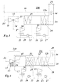
Fig. 1 vergleichbaren Darstellung ein erstes Ausführungsbeispiel eines Kombikraftwerks nach der Erfindung mit Nutzbarmachung der latenten Wärme des im Abgas enthaltenen Wasserdampfs durch einen Niedertemperaturkreislauf; - Fig. 3
- in einer zu
Fig. 2 vergleichbaren Darstellung ein zweites Ausführungsbeispiel eines Kombikraftwerks nach der Erfindung mit Nutzbarmachung der latenten Wärme des im Abgas enthaltenen Wasserdampfs durch einen Niedertemperaturkreislauf sowie zusätzlicher Abgasrückführung; - Fig. 4
- in einer zu
Fig. 2 vergleichbaren Darstellung ein drittes Ausführungsbeispiel eines Kombikraftwerks nach der Erfindung mit Nutzbarmachung der latenten Wärme des im Abgas enthaltenen Wasserdampfs durch einen Niedertemperaturkreislauf sowie zusätzlicher Verdampfungskühlung des Verdichters durch das bei der Nutzbarmachung der latenten Wärme anfallende Wasser und Vorwärmen der verdichteten Luft in einem Rekuperator.
- Fig. 1
- a highly simplified system diagram of a combined cycle power plant with a gas turbine with sequential combustion according to the prior art;
- Fig. 2
- in one too
Fig. 1 comparable representation of a first embodiment of a combined cycle power plant according to the invention with utilization of the latent heat of the water vapor contained in the exhaust gas through a low-temperature circuit; - Fig. 3
- in one too
Fig. 2 comparable illustration of a second embodiment of a combined cycle power plant according to the invention with utilization of the latent heat of the water vapor contained in the exhaust gas through a low-temperature circuit and additional exhaust gas recirculation; - Fig. 4
- in one too
Fig. 2 Comparative illustration of a third embodiment of a combined cycle power plant according to the invention with utilization of the latent heat of the exhaust gas Water vapor contained by a low-temperature circuit and additional evaporative cooling of the compressor by the accumulation of latent heat occurring water and preheating the compressed air in a recuperator.
Ein wesentliches Merkmal der vorliegende Erfindung ist es, bei einem Kombikraftwerk dem im Abgas durch den Abhitzedampferzeuger mitgeführten Wasserdampf durch Kondensation am kalten Ende des Abhitzedampferzeugers im wesentlichen die latente Wärme zu entziehen und zum Betreiben eines Niedertemperaturkreislaufs zu verwenden, um zusätzliche Energie zu erzeugen. Dazu werden am kalten Ende des Abhitzedampferzeugers zusätzliche Heizflächen angeordnet, die von Arbeitsmittel des Niedertemperaturkreislaufs durchströmt werden und einen Verdampfer bilden. Mithilfe dieses Verdampfers wird Wärme in den Niedertemperaturkreislauf übertragen und dort zum Betrieb einer entsprechenden Turbine verwendet. Ein wesentlicher Teil dieser übertragenen Wärme ist die latente Wärme des im Abgas mitgeführten Wasserdampfs. Das entstehende Kondensat kann grundsätzlich abgeführt werden. Besonders vorteilhaft ist es jedoch, das Kondensat zumindest teilweise zur Kühlung des Verdichters der Gasturbine zu verwenden. Dadurch verringert sich einerseits die Kompressorleistung merklich und es ergibt sich andererseits ein Wasser-Dampfkreislauf im gasseitigen 'Topping Cycle' Kombianlage. Das erhöht den Dampfgehalt der Abgase und damit auch die latente Wärme, welche am kalten Ende genutzt werden kann.An essential feature of the present invention is, in a combined cycle power plant, to substantially remove the latent heat from condensation carried at the cold end of the heat recovery steam generator by the heat recovery steam generator and to use it to operate a low temperature circuit to generate additional energy. For this purpose, additional heating surfaces are arranged at the cold end of the heat recovery steam generator, which are flowed through by working medium of the low-temperature circuit and form an evaporator. With the help of this evaporator heat is transferred to the low-temperature circuit and used there to operate a corresponding turbine. An essential part of this transferred heat is the latent heat of the entrained in the exhaust water vapor. The resulting condensate can always be removed. However, it is particularly advantageous to use the condensate at least partially for cooling the compressor of the gas turbine. As a result, on the one hand, the compressor power is noticeably reduced and, on the other hand, there is a water-steam cycle in the gas-side 'Topping Cycle' combined-cycle system. This increases the vapor content of the exhaust gases and thus also the latent heat, which can be used at the cold end.
In
Der Niedertemperaturkreislauf 23 umfasst den Verdampfer 24, eine Turbine 25, einen Kondensator 26 und einer Pumpe 27, die das im Kreis zirkulierende, im Kondensator 26 verflüssigte Arbeitsmittel zum Verdampfer 24 zurück pumpt. Grundsätzlich kann als Arbeitsmittel ein geeignetes Kältemittel verwendet werden. Aus Sicherheitsgründen ist es jedoch vorteilhaft, in der Kraftwerksumgebung CO2 als Arbeitsmittel im Niedertemperaturkreislauf 23 zu verwenden. Dies bietet die folgenden Vorteile:
- ● der Wärmeaustausch mit dem Abgas findet bei einem überkritischen CO2-Druck statt; dies ermöglicht eine geschickte Anpassung an das
Temperaturprofil im Abhitzedampferzeuger 12a; - ● die chemischen Gefahren werden minimiert; unvermeidbare Lecks im Kessel verursachen keine Schäden, wenn das ausströmende Medium mit dem Abgas in die Umwelt gelangt; und
- ● es gibt Synergie-Effekte im Zusammenhang mit den aktuellen verfahrenstechnischen und apparativen Bemühungen um die Abscheidung von CO2.
- ● the heat exchange with the exhaust gas takes place at supercritical CO2 pressure; this allows a clever adaptation to the temperature profile in the heat
recovery steam generator 12a; - ● the chemical hazards are minimized; unavoidable leaks in the boiler will not cause any damage if the escaping medium enters the environment with the exhaust gas; and
- ● There are synergy effects in connection with the current process and apparatus efforts for the capture of CO2.
Mit dem Niedertemperaturkreislauf 23 erhöht sich die Leistung und -der Wirkungsgrad des Kombikraftwerkes 10a. Die Temperatur des Abgases 34 wird durch den Verdampfer 24 erniedrigt. Der Verdampfer 24 liefert einen Massenstrom des Arbeitsmittels (CO2), der in der Turbine 25 eine hohe Leistung erzeugt. Das Arbeitsmittel wird im Kondensator 26 abgekühlt und verflüssigt. An den Wärmetauscherflächen des Verdampfers 24 kondensiert Wasser aus dem Abgas 34 und wird von einem Wassersammler 28 aufgefangen. Bei den vorgegebenen Parametern fällt am Wassersammler 28 ein hoher Wasserstrom an.With the
Der Niedertemperaturkreislauf 23 am Abhitzedampferzeuger 12a kann im Zusammenhang mit einer CO2-Abscheidung von Vorteil sein. Ein entsprechendes Ausführungsbeispiel ist in
- ● der Wirkungsgrad des Kombikraftwerkes erhöht sich mit dem Niedertemperaturkreislauf;
- ● die in
Fig. 3 dargestellte Konfiguration macht es möglich, dasselbe Anlagenschema für beide Anwendungen einzusetzen, nämlich herkömmliche Kombikraftwerke und Anlagen mit CO2-Abscheidung; - ● die Ausgangsleistung des Niedertemperaturkreislaufs verringert die Leistungseinbusse durch die CO2-Abscheidung;
- ● im Fall der CO2-Abscheidung verbessert sich die Ökonomie des Niedertemperaturkreislaufs; und
- ● die Abgasrückführung verschiebt möglicherweise die Grenze für die Heissgastemperatur im Hinblick auf die Erzeugung von NOx.
- ● the efficiency of the combined cycle power plant increases with the low-temperature cycle;
- ● the in
Fig. 3 The configuration shown makes it possible to use the same plant scheme for both applications, namely conventional combined cycle power plants and CO2 capture plants; - ● the output power of the low temperature circuit reduces the power penalty due to CO2 capture;
- ● in the case of CO2 capture, the economy of the low-temperature cycle improves; and
- ● Exhaust gas recirculation may shift the limit for the hot gas temperature with respect to the generation of NOx.
Die Wellenleistung am Verdichter trägt bei weitem am meisten zu den Verlusten im Kombikraftwerk bei. Das bei der Latentwärme-Nutzung anfallende Wasser kann daher (bei entsprechender Vorbehandlung) mit Vorteil zur Kühlung im Verdichter 13 eingesetzt werden, um die Verdichtungsarbeit in der Gasturbine 11 zu reduzieren. Die maximale Verdampfungskühlung durch Einspritzen wird dadurch erreicht, dass nach jeder Verdichtungsstufe genauso viel Wasser eingespritzt wird, wie nötig ist, um die Luft bis zum Taupunkt abzukühlen.The shaft power at the compressor contributes by far the most to the losses in the combined cycle power plant. The resulting in the use of latent heat water can therefore (with appropriate pretreatment) advantageously be used for cooling in the
Des Weiteren wird die vom Verdichter 13 angesaugte Luft nach der Verdichtung in einem Rekuperator im Abhitzedampferzeuger vorgewärmt, um den Brennstoffverbrauch zu reduzieren. Ein entsprechendes Ausführungsbeispiel eines solchen Kombikraftwerkes ist in
Weiterhin ist in Strömungsrichtung auf der Höhe des Verdampfers 19 ein Rekuperator 31 im Abhitzedampferzeuger 12b eingebaut, der die im Verdichter 13 verdichtete Luft weiter erhitzt. Die vom Verdichter 13 verbrauchte Leistung reduziert sich durch die Kühlung. Der Wassergehalt im Abgas erhöht sich. Die von der Dampfturbine 20 abgegebene Leistung sich reduziert, dafür erhöht sich die Leistung der Turbine 25.Ausserdem wird deutlich mehr Brennstoff zugeführt, wodurch sich die Leistung der Turbine 15 erhöht. Die gesamte Leistung des Kombikraftwerkes 10c erhöht sich bei gleichem Luftmassenstrom 16 um mehr als 30 %. Dies ist zum Teil eine Folge des zusätzlich eingespritzten Wassers. Ein weiterer signifikanter Beitrag ergibt sich daraus, dass sich die spezifische Wärme des Mediums mit steigendem Wassergehalt erhöht. Der Wirkungsgrad nimmt jedoch wegen der reduzierten Kompressorleistung zu.Furthermore, a
Beim Betrieb ist die Luft, die im Verdichter 13 verdichtet wird, im Rekuperator 31 zugeführt. Im Rekuperator 31 wird die Lufttemperatur erhöht, ohne den Kompressor damit zu beeinflussen.During operation, the air that is compressed in the
Der Verdichter 13 wird durch Wasser gekühlt. Vorteilhaft ist Wasser, die im Wassersammler 28 erholt wird, dem Verdichter 13 zugeführt. Ausserdem, erholt man bei dem Wassersammler 28 zusätzliches Wasser, das für anderen Zwecke benutzbar ist. Ein entscheidender Vorteil des verdampfungsgekühlten Verdichters 13 liegt darin, dass das Verdichtungsverhältnis und die Temperaturen der in die Brennkammer 14 strömenden heissen Luft entkoppelt werden. In der Anlage Gemäss
In den bisherigen Ausführungsbeispielen wurde die Verbrennungstemperatur konstant gehalten. In der vorgeschlagenen Anlagenkonfiguration kann jedoch die Verbrennungstemperatur erhöht werden. In diesem Fall macht sich der Vorteil der sequenziellen Verbrennung (zwei Brennkammern, zwei Turbinen) bemerkbar: das Druckniveau in der zweiten Brennkammer (SEV) kann so gewählt werden, dass sich für den Niedertemperaturkreislauf 23 optimale Bedingungen ergeben.In the previous embodiments, the combustion temperature was kept constant. However, in the proposed plant configuration, the combustion temperature may be increased. In this case, the advantage of sequential combustion (two combustion chambers, two turbines) becomes noticeable: the pressure level in the second combustion chamber (SEV) can be chosen so that optimum conditions for the low-
Bei Kombikraftwerken wird davon ausgegangen, dass es ökonomisch nicht sinnvoll ist, die Dampftemperatur über etwa 600ºC bis 620ºC hinaus zu erhöhen. Dies würde zu einem massiven Einsatz von teuren Nickelbasislegierungen für die mit Druck beaufschlagten Komponenten führen. Es wird deshalb vorgeschlagen, den Druck einer zweiten Brennkammer (SEV) so auszuwählen, dass sich eine Auslasstemperatur der Gasturbine in einem akzeptablen Bereich ergibt.Combined cycle power plants assume that it does not make economic sense to increase the steam temperature beyond about 600 ° C to 620 ° C. This would result in massive use of expensive nickel base alloys for the pressurized components. It is therefore proposed to select the pressure of a second combustion chamber (SEV) so that an outlet temperature of the gas turbine results in an acceptable range.
Im Übrigen versteht sich von selbst, dass die Abgasrückführung gemäss
- 10,10a-c10,10a-c
- KombikraftwerkCombined cycle power plant
- 11,11a11,11a
- Gasturbinegas turbine
- 12,12a,b12,12a, b
- Abhitzedampferzeugerheat recovery steam generator
- 1313
- Verdichtercompressor
- 1414
- Brennkammercombustion chamber
- 1515
- Turbineturbine
- 1616
- LuftmassenstromAir mass flow
- 16'16 '
- Ansaugmassenstromintake mass flow
- 1717
- Brennstoffzufuhrfuel supply
- 1818
- Wasser-Dampf-KreislaufWater-steam cycle
- 19,2419.24
- VerdampferEvaporator
- 2020
- Dampfturbinesteam turbine
- 21,2621.26
- Kondensatorcapacitor
- 2222
- SpeisewasserpumpeFeedwater pump
- 2323
- Niedertemperaturkreislauf (z.B. Organic Rankine Cycle ORC)Low Temperature Circuit (e.g., Organic Rankine Cycle ORC)
- 2525
- Turbineturbine
- 2727
- Pumpepump
- 2828
- Wassersammlerwater collector
- 2929
- Abgaskaminexhaust stack
- 3030
- AbgasrückführungExhaust gas recirculation
- 3131
- Rekuperatorrecuperator
- 3232
- Vorwärmerpreheater
- 3333
- Einspritzvorrichtung (Verdampfungskühlung)Injector (evaporative cooling)
Claims (15)
Priority Applications (1)
| Application Number | Priority Date | Filing Date | Title |
|---|---|---|---|
| EP11178136A EP2559867A1 (en) | 2011-08-19 | 2011-08-19 | Method for generating electrical energy with a combination power plant and combination power plant and device for carrying out the method |
Applications Claiming Priority (1)
| Application Number | Priority Date | Filing Date | Title |
|---|---|---|---|
| EP11178136A EP2559867A1 (en) | 2011-08-19 | 2011-08-19 | Method for generating electrical energy with a combination power plant and combination power plant and device for carrying out the method |
Publications (1)
| Publication Number | Publication Date |
|---|---|
| EP2559867A1 true EP2559867A1 (en) | 2013-02-20 |
Family
ID=44773971
Family Applications (1)
| Application Number | Title | Priority Date | Filing Date |
|---|---|---|---|
| EP11178136A Withdrawn EP2559867A1 (en) | 2011-08-19 | 2011-08-19 | Method for generating electrical energy with a combination power plant and combination power plant and device for carrying out the method |
Country Status (1)
| Country | Link |
|---|---|
| EP (1) | EP2559867A1 (en) |
Cited By (3)
| Publication number | Priority date | Publication date | Assignee | Title |
|---|---|---|---|---|
| DE102016220634A1 (en) * | 2016-10-20 | 2018-04-26 | Siemens Aktiengesellschaft | Waste heat power plant with gradual heat supply |
| WO2019016766A1 (en) * | 2017-07-20 | 2019-01-24 | 8 Rivers Capital, Llc | System and method for power production with solid fuel combustion and carbon capture |
| US20210239041A1 (en) * | 2018-05-04 | 2021-08-05 | Spada Srl | Apparatus, process and thermodynamic cycle for power generation with heat recovery |
Citations (9)
| Publication number | Priority date | Publication date | Assignee | Title |
|---|---|---|---|---|
| EP0770771A1 (en) | 1995-10-26 | 1997-05-02 | Asea Brown Boveri Ag | Compressor with intercooling |
| EP0978635A1 (en) | 1998-08-05 | 2000-02-09 | Asea Brown Boveri AG | Process for cooling the thermally stressed structures of a power plant |
| DE19900026A1 (en) | 1999-01-02 | 2000-07-06 | Asea Brown Boveri | Gas turbine with direct steam injection has compressor unit supplied with steam, water from waste heat steam generator, or fresh water from outside |
| EP1138955A2 (en) | 2000-03-29 | 2001-10-04 | Watson Cogeneration Company | Method and apparatus for increasing the efficiency of a multi-stage compressor |
| WO2004010003A2 (en) | 2002-07-14 | 2004-01-29 | Rerum Cognitio Gesellschaft Für Marktintegration Deutscher Innovation Und Forschungsprodukte Mbh | Method for compressing the working fluid during a water/steam combination process |
| US20040255587A1 (en) | 2003-06-17 | 2004-12-23 | Utc Power, Llc | Organic rankine cycle system for use with a reciprocating engine |
| US20060048515A1 (en) | 2000-07-17 | 2006-03-09 | Ormat Technologies, Inc. | Method of and apparatus for producing power from a heat source |
| DE102009022491A1 (en) * | 2009-05-25 | 2011-01-05 | Kirchner, Hans Walter, Dipl.-Ing. | Process for combining power plant with steam injected gas turbine and high pressure steam turbine, involves utilizing task obtained in high pressure steam turbine and steam injected gas turbine for current generation |
| EP2295764A1 (en) * | 2009-08-18 | 2011-03-16 | Siemens Aktiengesellschaft | Method for operating a power plant assembly and power plant assembly |
-
2011
- 2011-08-19 EP EP11178136A patent/EP2559867A1/en not_active Withdrawn
Patent Citations (9)
| Publication number | Priority date | Publication date | Assignee | Title |
|---|---|---|---|---|
| EP0770771A1 (en) | 1995-10-26 | 1997-05-02 | Asea Brown Boveri Ag | Compressor with intercooling |
| EP0978635A1 (en) | 1998-08-05 | 2000-02-09 | Asea Brown Boveri AG | Process for cooling the thermally stressed structures of a power plant |
| DE19900026A1 (en) | 1999-01-02 | 2000-07-06 | Asea Brown Boveri | Gas turbine with direct steam injection has compressor unit supplied with steam, water from waste heat steam generator, or fresh water from outside |
| EP1138955A2 (en) | 2000-03-29 | 2001-10-04 | Watson Cogeneration Company | Method and apparatus for increasing the efficiency of a multi-stage compressor |
| US20060048515A1 (en) | 2000-07-17 | 2006-03-09 | Ormat Technologies, Inc. | Method of and apparatus for producing power from a heat source |
| WO2004010003A2 (en) | 2002-07-14 | 2004-01-29 | Rerum Cognitio Gesellschaft Für Marktintegration Deutscher Innovation Und Forschungsprodukte Mbh | Method for compressing the working fluid during a water/steam combination process |
| US20040255587A1 (en) | 2003-06-17 | 2004-12-23 | Utc Power, Llc | Organic rankine cycle system for use with a reciprocating engine |
| DE102009022491A1 (en) * | 2009-05-25 | 2011-01-05 | Kirchner, Hans Walter, Dipl.-Ing. | Process for combining power plant with steam injected gas turbine and high pressure steam turbine, involves utilizing task obtained in high pressure steam turbine and steam injected gas turbine for current generation |
| EP2295764A1 (en) * | 2009-08-18 | 2011-03-16 | Siemens Aktiengesellschaft | Method for operating a power plant assembly and power plant assembly |
Non-Patent Citations (2)
| Title |
|---|
| BIDINI G ET AL: "Optimization of an integrated gas turbine-geothermal power plant", ENERGY CONVERSION AND MANAGEMENT, ELSEVIER SCIENCE PUBLISHERS, OXFORD, GB, vol. 39, no. 16-18, 1 November 1998 (1998-11-01), pages 1945 - 1956, XP004523611, ISSN: 0196-8904, DOI: 10.1016/S0196-8904(98)00056-9 * |
| KOROBITSYN M: "ENHANCING DIRECT-FIRED POWER PLANTS PERFORMANCE BY USE OF GAS TURBINE TECHNOLOGY", JOURNAL OF PROPULSION AND POWER, AMERICAN INSTITUTE OF AERONAUTICS AND ASTRONAUTICS. NEW YORK, US, vol. 16, no. 4, 1 July 2000 (2000-07-01), pages 568 - 571, XP000937216, ISSN: 0748-4658 * |
Cited By (4)
| Publication number | Priority date | Publication date | Assignee | Title |
|---|---|---|---|---|
| DE102016220634A1 (en) * | 2016-10-20 | 2018-04-26 | Siemens Aktiengesellschaft | Waste heat power plant with gradual heat supply |
| WO2019016766A1 (en) * | 2017-07-20 | 2019-01-24 | 8 Rivers Capital, Llc | System and method for power production with solid fuel combustion and carbon capture |
| JP2020528121A (en) * | 2017-07-20 | 2020-09-17 | 8 リバーズ キャピタル,エルエルシー | Systems and methods for power generation involving the combustion of solid fuels and the recovery of carbon dioxide |
| US20210239041A1 (en) * | 2018-05-04 | 2021-08-05 | Spada Srl | Apparatus, process and thermodynamic cycle for power generation with heat recovery |
Similar Documents
| Publication | Publication Date | Title |
|---|---|---|
| EP0076529B1 (en) | Nox reduction for gas turbines by water injection into the combustion chamber | |
| EP3362739B1 (en) | Generation of process steam by means of a high-temperature heat pump | |
| DE102004039164A1 (en) | Method for generating energy in a gas turbine comprehensive power generation plant and power generation plant for performing the method | |
| EP0674099A1 (en) | Cooling method for the thermically charged components of a gasturbine powerplant | |
| AT517535B1 (en) | Steam power plant | |
| EP2447506A2 (en) | System for generating mechanical and/or electrical energy | |
| WO2008067855A2 (en) | Method and apparatus for increasing the performance and efficiency of an orc power plant process | |
| DE102011056910A1 (en) | System and method for utilizing the heat of a gas turbine intercooler in a bottoming steam process | |
| DE102009044088A1 (en) | Peak load management through combined cycle energy boost using peak cycle exhaust heat recovery | |
| EP2423465A2 (en) | Method for operating a steam turbine power plant and device for generating steam | |
| EP1105624B1 (en) | Gas and steam turbine unit | |
| EP1099041B1 (en) | Gas and steam turbine installation | |
| EP1038094B1 (en) | Multistep steam power operating method for generating electric power in a cycle and device for the implementation thereof | |
| DE10055202A1 (en) | Electrical generation steam cycle with increased efficiency, branches off working fluid and condenses it for cooling during expansion process | |
| WO2005056994A1 (en) | Air-storage plant | |
| DE102010003676A1 (en) | Separator for CO2 and power plant | |
| EP2559867A1 (en) | Method for generating electrical energy with a combination power plant and combination power plant and device for carrying out the method | |
| DE102012110579B4 (en) | Plant and process for generating process steam | |
| EP0158629B1 (en) | Steam cycle for a steam power plant | |
| EP1507069A1 (en) | Method and installation for recovering water in a power plant | |
| EP2480763B1 (en) | Steam power station | |
| EP3728800B1 (en) | Power plant | |
| EP2385223A1 (en) | Procedure for the increase of the efficiency of gas and steam turbine power plants | |
| DE102004040730B3 (en) | Method and apparatus for utilizing waste heat | |
| EP3862547B1 (en) | Gas turbine arrangement and method of operating a gas turbine arrangement |
Legal Events
| Date | Code | Title | Description |
|---|---|---|---|
| PUAI | Public reference made under article 153(3) epc to a published international application that has entered the european phase |
Free format text: ORIGINAL CODE: 0009012 |
|
| AK | Designated contracting states |
Kind code of ref document: A1 Designated state(s): AL AT BE BG CH CY CZ DE DK EE ES FI FR GB GR HR HU IE IS IT LI LT LU LV MC MK MT NL NO PL PT RO RS SE SI SK SM TR |
|
| AX | Request for extension of the european patent |
Extension state: BA ME |
|
| STAA | Information on the status of an ep patent application or granted ep patent |
Free format text: STATUS: THE APPLICATION IS DEEMED TO BE WITHDRAWN |
|
| 18D | Application deemed to be withdrawn |
Effective date: 20130821 |