EP2559637A1 - Method for contamination prevention in fluid storage tank requiring temperature control, and device therefor - Google Patents
Method for contamination prevention in fluid storage tank requiring temperature control, and device therefor Download PDFInfo
- Publication number
- EP2559637A1 EP2559637A1 EP11768827A EP11768827A EP2559637A1 EP 2559637 A1 EP2559637 A1 EP 2559637A1 EP 11768827 A EP11768827 A EP 11768827A EP 11768827 A EP11768827 A EP 11768827A EP 2559637 A1 EP2559637 A1 EP 2559637A1
- Authority
- EP
- European Patent Office
- Prior art keywords
- pressure
- cooling
- heating medium
- storage tank
- atm
- Prior art date
- Legal status (The legal status is an assumption and is not a legal conclusion. Google has not performed a legal analysis and makes no representation as to the accuracy of the status listed.)
- Granted
Links
- 238000003860 storage Methods 0.000 title claims abstract description 232
- 239000012530 fluid Substances 0.000 title claims abstract description 172
- 238000000034 method Methods 0.000 title claims abstract description 25
- 238000011109 contamination Methods 0.000 title claims abstract description 21
- 230000002265 prevention Effects 0.000 title 1
- 238000010438 heat treatment Methods 0.000 claims abstract description 281
- 238000001816 cooling Methods 0.000 claims abstract description 277
- 239000007788 liquid Substances 0.000 claims abstract description 64
- XLYOFNOQVPJJNP-UHFFFAOYSA-N water Substances O XLYOFNOQVPJJNP-UHFFFAOYSA-N 0.000 claims description 21
- 238000010276 construction Methods 0.000 claims description 5
- 238000005070 sampling Methods 0.000 claims description 4
- 238000007789 sealing Methods 0.000 claims description 3
- 239000002826 coolant Substances 0.000 description 4
- LYCAIKOWRPUZTN-UHFFFAOYSA-N Ethylene glycol Chemical compound OCCO LYCAIKOWRPUZTN-UHFFFAOYSA-N 0.000 description 3
- DNIAPMSPPWPWGF-UHFFFAOYSA-N Propylene glycol Chemical compound CC(O)CO DNIAPMSPPWPWGF-UHFFFAOYSA-N 0.000 description 3
- 230000037452 priming Effects 0.000 description 3
- 238000009423 ventilation Methods 0.000 description 3
- 235000013372 meat Nutrition 0.000 description 2
- 239000002184 metal Substances 0.000 description 2
- 229910052751 metal Inorganic materials 0.000 description 2
- 238000002360 preparation method Methods 0.000 description 2
- 241000894006 Bacteria Species 0.000 description 1
- 230000002159 abnormal effect Effects 0.000 description 1
- 230000005856 abnormality Effects 0.000 description 1
- 235000013334 alcoholic beverage Nutrition 0.000 description 1
- 230000002528 anti-freeze Effects 0.000 description 1
- 235000013361 beverage Nutrition 0.000 description 1
- 230000001276 controlling effect Effects 0.000 description 1
- 238000007796 conventional method Methods 0.000 description 1
- 239000000498 cooling water Substances 0.000 description 1
- 230000007547 defect Effects 0.000 description 1
- 238000001514 detection method Methods 0.000 description 1
- 230000000694 effects Effects 0.000 description 1
- 238000004817 gas chromatography Methods 0.000 description 1
- 230000005484 gravity Effects 0.000 description 1
- 238000004811 liquid chromatography Methods 0.000 description 1
- 230000014759 maintenance of location Effects 0.000 description 1
- 238000004519 manufacturing process Methods 0.000 description 1
- 239000000463 material Substances 0.000 description 1
- 239000008267 milk Substances 0.000 description 1
- 210000004080 milk Anatomy 0.000 description 1
- 235000013336 milk Nutrition 0.000 description 1
- 229920000915 polyvinyl chloride Polymers 0.000 description 1
- 239000004800 polyvinyl chloride Substances 0.000 description 1
- 239000000843 powder Substances 0.000 description 1
- 238000005057 refrigeration Methods 0.000 description 1
- 230000001105 regulatory effect Effects 0.000 description 1
Images


Classifications
-
- B—PERFORMING OPERATIONS; TRANSPORTING
- B65—CONVEYING; PACKING; STORING; HANDLING THIN OR FILAMENTARY MATERIAL
- B65D—CONTAINERS FOR STORAGE OR TRANSPORT OF ARTICLES OR MATERIALS, e.g. BAGS, BARRELS, BOTTLES, BOXES, CANS, CARTONS, CRATES, DRUMS, JARS, TANKS, HOPPERS, FORWARDING CONTAINERS; ACCESSORIES, CLOSURES, OR FITTINGS THEREFOR; PACKAGING ELEMENTS; PACKAGES
- B65D90/00—Component parts, details or accessories for large containers
- B65D90/22—Safety features
-
- B—PERFORMING OPERATIONS; TRANSPORTING
- B65—CONVEYING; PACKING; STORING; HANDLING THIN OR FILAMENTARY MATERIAL
- B65D—CONTAINERS FOR STORAGE OR TRANSPORT OF ARTICLES OR MATERIALS, e.g. BAGS, BARRELS, BOTTLES, BOXES, CANS, CARTONS, CRATES, DRUMS, JARS, TANKS, HOPPERS, FORWARDING CONTAINERS; ACCESSORIES, CLOSURES, OR FITTINGS THEREFOR; PACKAGING ELEMENTS; PACKAGES
- B65D88/00—Large containers
- B65D88/74—Large containers having means for heating, cooling, aerating or other conditioning of contents
- B65D88/744—Large containers having means for heating, cooling, aerating or other conditioning of contents heating or cooling through the walls or internal parts of the container, e.g. circulation of fluid inside the walls
-
- B—PERFORMING OPERATIONS; TRANSPORTING
- B08—CLEANING
- B08B—CLEANING IN GENERAL; PREVENTION OF FOULING IN GENERAL
- B08B17/00—Methods preventing fouling
-
- B—PERFORMING OPERATIONS; TRANSPORTING
- B65—CONVEYING; PACKING; STORING; HANDLING THIN OR FILAMENTARY MATERIAL
- B65D—CONTAINERS FOR STORAGE OR TRANSPORT OF ARTICLES OR MATERIALS, e.g. BAGS, BARRELS, BOTTLES, BOXES, CANS, CARTONS, CRATES, DRUMS, JARS, TANKS, HOPPERS, FORWARDING CONTAINERS; ACCESSORIES, CLOSURES, OR FITTINGS THEREFOR; PACKAGING ELEMENTS; PACKAGES
- B65D90/00—Component parts, details or accessories for large containers
- B65D90/48—Arrangements of indicating or measuring devices
- B65D90/50—Arrangements of indicating or measuring devices of leakage-indicating devices
-
- Y—GENERAL TAGGING OF NEW TECHNOLOGICAL DEVELOPMENTS; GENERAL TAGGING OF CROSS-SECTIONAL TECHNOLOGIES SPANNING OVER SEVERAL SECTIONS OF THE IPC; TECHNICAL SUBJECTS COVERED BY FORMER USPC CROSS-REFERENCE ART COLLECTIONS [XRACs] AND DIGESTS
- Y10—TECHNICAL SUBJECTS COVERED BY FORMER USPC
- Y10T—TECHNICAL SUBJECTS COVERED BY FORMER US CLASSIFICATION
- Y10T137/00—Fluid handling
- Y10T137/0318—Processes
- Y10T137/0396—Involving pressure control
-
- Y—GENERAL TAGGING OF NEW TECHNOLOGICAL DEVELOPMENTS; GENERAL TAGGING OF CROSS-SECTIONAL TECHNOLOGIES SPANNING OVER SEVERAL SECTIONS OF THE IPC; TECHNICAL SUBJECTS COVERED BY FORMER USPC CROSS-REFERENCE ART COLLECTIONS [XRACs] AND DIGESTS
- Y10—TECHNICAL SUBJECTS COVERED BY FORMER USPC
- Y10T—TECHNICAL SUBJECTS COVERED BY FORMER US CLASSIFICATION
- Y10T137/00—Fluid handling
- Y10T137/6416—With heating or cooling of the system
Definitions
- the present invention relates to a method for preventing, in a fluid storage tank which requires temperature control, a liquid cooling or heating medium that flows and circulates in an enclosed pressure-resistant jacket provided around an outer wall of said fluid storage tank from entering into said fluid storage tank during breakage failure of the wall of said storage tank, as well as a plant therefore.
- a storage tank for storing a large amount of materials has come to be used in accordance with development of industrialization of manufacturing of various products. It is generalized to monitor (control) or maintain the temperature in the tank in compliance with the properties and use of the fluid stored in the tank.
- a conventional plant which monitors (controls) or maintains the temperature in a fluid storage tank 22 as shown in Fig. 9 can be generally accomplished by allowing a liquid cooling or heating medium to flow in an enclosed pressure-resistant jacket 24 provided around an outer wall of the fluid storage tank by means of a pressurization pump 27 and returning it to a cooling or heating medium-storage tank 23.
- the temperature of the cooling or heating medium in said cooling or heating medium-storage tank 23 is regulated by a temperature control unit 28.
- An object of the present invention is to provide a method and a plant for preventing contamination of a fluid in a fluid storage tank with a liquid cooling or heating medium, in view of the problems involved in the conventional fluid storage tanks.
- Another object of the present invention is to provide a method and a device for detecting small breakage failures such as cracks, pinholes or the like in the wall of a fluid storage tank in a simple and easy way.
- x supercharged pressure, reduced pressure or normal pressure, usually normal pressure of about 1 atm
- the enclosed pressure-resistant jacket is made to have a multistage construction with two or more staged enclosed pressure-resistant jackets, said first stage having the structure of the enclosed pressure-resistant jacket as described above, each of the second and subsequent stages being provided with (i) an enclosed pressure-resistant jacket and (ii) a server tank provided separately from the fluid storage tank or a pressure reduction unit and arranged between the cooling or heating medium-storage tank and each enclosed pressure-resistant jacket, preferably the bottom of the enclosed pressure-resistant jacket, wherein, in the case where the server tank is provided, the height A' from the liquid level of the fluid in each of the server tank to the bottom of each enclosed pressure-resistant jacket is set to satisfy the following equation: A ⁇
- a pressure-reduction unit used in the plant of the present invention, which comprises a pressure-reduction valve for reducing the pressure of a pressurized cooling or heating medium and maintaining it at a constant pressure, and a pressure differential valve for further reducing the pressure of the cooling or heating medium.
- a method for detecting small breakages, such as cracks or pinholes, in a fluid storage tank in which the temperature of a fluid in said fluid storage tank is controlled by allowing a liquid cooling or heating medium to flow in an enclosed pressure-resistant jacket provided around the outside of a wall of the fluid storage tank, which comprises allowing the cooling or heating medium to flow in said enclosed pressure-resistant jacket at a pressure lower than a predetermined pressure x (atm) applied within the fluid storage tank, sampling the cooling or heating medium from an air pool provided in a passage of the cooling or heating medium, and analyzing the components of the cooling or heating medium, while at the same time preventing contamination of the fluid in the fluid storage tank with the liquid cooling or heating medium.
- a predetermined pressure x atm
- a physically pressure-reducing apparatus for physically and forcibly reducing the pressure in a space in which a cooling or heating medium flows, while stopping the flow in the space and sealing the space, under such circumstance where a reduced pressure in the space becomes difficult to be maintained for some causes but a reduced pressure is required, said apparatus being used in a method and plant in which contamination of a fluid storage tank which requires temperature control with the liquid cooling or heating medium is prevented.
- the cooling or heating medium is not entrained into the fluid in the storage tank since the pressure in the enclosed pressure-resistant jacket provided outside the storage tank is lower than that of the storage tank and thus the fluid in the storage tank flows into the enclosed pressure-resistant jacket.
- small breakages such as cracks, pinholes or the like generated in the wall of the fluid storage tank can be readily detected by sampling the cooling or heating medium and detecting contamination of the sample of the cooling or heating medium.
- the maximum suction height C max (m) of the cooling or heating medium by a suction pump depends on the efficacy of the pump.
- the maximum suction height C max (m) of the cooling or heating medium by a suction pump is defined as a maximum suction height (m) of water which is a typical cooling or heating medium.
- the height A, B and C are determined so that the heights A and B and the suction height C of the cooling or heating medium by a suction pump satisfy the following formula (equation or inequality) (1): A + B ⁇ C wherein,
- These heights A and B are adjusted to enable safe circulation considering the suction height of a cooling or heating medium by the suction pump C, the specific density of the cooling or heating medium, a required difference in pressure (atm) between a pressure (atm) at the bottom of the enclosed pressure-resistant jacket and the pressure x (atm) within the fluid storage tank, a safe operational value, and atmospheric pressure.
- a reduced-pressure circulation of the cooling or heating medium can be enable by using a pressure-reduction unit, and during cessation of a suction pump, it is possible to maintain the pressure in the enclosed pressure-resistant jacket not higher than that in a fluid storage tank (reduce pressure retention) by using a combination of an electromagnetic valve and a physically pressure-reducing apparatus.
- the suction height of a cooling or heating medium C(m) is set up by the following formula (4):
- C C max - S / ⁇ (wherein, C max , S, and ⁇ are as defined above). It is necessary to set up the safe operational value S(m) taking account of drop of the suction efficacy of the suction pump due to metal fatigue or the like.
- B is set up according to the following formula (7): B ⁇ C - W ⁇ 1 - E / ⁇ wherein, E (atm) is a pressure set up for the pressure reduction unit, and C, W and ⁇ are as defined above.
- the cooling or heating medium is sent from the cooling or heating medium-storage tank 3 to the bottom of the enclosed pressure-resistant jacket 4 via a cooling or heating medium-flow conduit line 5, aspirated to allow flowing in the enclosed pressure-resistant jacket 4 , and returned to the cooling or heating medium-storage tank 3 via a cooling or heating medium-flow conduit line 5, whereby allowing the cooling or heating medium in the enclosed pressure-resistant jacket 4 to flow always under a pressure lower than that in the fluid storage tank 2 (a pressure which is relatively lower than that inside the fluid storage tank 2 which is usually not higher than 1 atm).
- An air pool 9 may be provided in the in a cooling or heating medium flow pipe 5 arranged between the suction pump 1 and the cooling or heating medium-storage tank 3, preferably near the cooling or heating medium-storage tank 3, and at a height not higher than the liquid level of the cooling or heating medium-storage tank 3.
- the temperature of the cooling or heating medium in the cooling or heating medium-storage tank 3 can be controlled by a temperature-control equipment 8.
- a server tank 10 may be provided at a level below and near the fluid storage tank 2.
- the cooling or heating medium supplied from the cooling or heating medium-storage tank 3 is pressurized by a pressurizing pump 17, and sent to the server tank 10. Thereafter, the cooling or heating medium from the server tank 10 is circulated under a reduce pressure in the enclosed pressure-resistant jacket 4, and returned to the cooling or heating medium-storage tank 3.
- the server tank 10 It is preferable to provide the server tank 10 with a vent (ventilation pipe), make the server tank 10 open to the air in place of enclosing it, and provide with a ball tap to regulate a flow volume of the cooling or heating medium from the cooling or heating medium-storage tank 3.
- a vent ventilation pipe
- a ball tap to regulate a flow volume of the cooling or heating medium from the cooling or heating medium-storage tank 3.
- an electromagnetic valve 13 may be arranged downstream the suction pump 1, as shown in Fig. 2 .
- a cooling or heating medium-receiver tank 11 between the suction pump 1 arranged near the exit of the cooling or heating medium of the enclosed pressure-resistant jacket 4 and the cooling or heating medium-storage tank 3, providing the cooling or heating medium-receiver tank 11 with a level sensor (not shown) which cooperates with the suction pump 1, it is also possible to regulate a liquid level of the cooling or heating medium-receiver tank 11.
- a pressure-reduction unit 12 is provided in preparation for cessation of the pump to reduce a pressure in conduit lines in place of setting up the liquid level of the cooling or heating medium-storage tank 3 below the bottom of the fluid storage tank 2.
- a physically pressure-reducing apparatus 14 is provided between the exit of the enclosed pressure-resistant jacket 4 and the suction pump 1 to forcibly reduce the pressure in the enclosed pressure-resistant jacket 4, instead of controlling a pressure-reduced state in the enclosed pressure-resistant jacket 4 by the height.
- An electromagnetic valve 13 may be laid on to seal the enclosed pressure-resistant jacket 4 in preparation for cessation of the suction pump 1.
- the inside of the cooling or heating medium-storage tank and the enclosed pressure-resistant jacket are connected by a conduit line optionally via a cooling or heating medium-receiver tank 11, and the exit, usually arranged at the top, of the enclosed pressure-resistant jacket and an admission port of the suction pump 1 are connected by a conduit line, and further a discharge port of the suction pump 1 and the inside of the cooling or heating medium-storage tank 3 are connected by a conduit line.
- cooling or heating medium-storage tank It is necessary to provide the cooling or heating medium-storage tank with a ventilation hole (ventilation pipe). This is because it is necessary for the cooling or heating medium-storage tank 3 to be open to the air instead of making it closed.
- the reason therefor is that by returning a pressurized state of the returning (returning from suction pump 1 to cooling or heating medium-storage tank 3) cooling or heating medium in the conduit line to a normal pressure state, a conduit line for forwarding (forwarding from the cooling or heating medium-storage tank 3 to the enclosed pressure-resistant jacket 4) cooling or heating medium can be always maintained in a reduced state.
- the conduit line from the discharge port of the suction pump 1 may be inserted into the liquid of the cooling or heating medium-storage tank 3, or may be attached to the cooling or heating medium-storage tank 3 at a site of the wall thereof below the liquid level of the tank 3.
- an electromagnetic valve 13 which is closed in compliance with stopping of the suction pump 1 may be laid on between the enclosed pressure-resistant jacket 4 and the cooling or heating medium-storage tank 3.
- the method and plat for preventing contamination of a fluid in a fluid storage tank 2 with a cooling or heating medium by making an enclosed pressure-resistant jacket 4 provided around the outer wall of the fluid storage tank 2 in a pressure-reduced state are meant a method and plant in which the enclosed pressure-resistant jacket 4 is always maintained in a pressure-reduced state (a state which is relatively lower in pressure compared with a pressure within the fluid storage tank 2), and the method and plant are not necessarily restricted to the embodiments shown above.
- the enclosed pressure-resistant jacket is constructed to a multiple staged (multistage) construction having a server tank and/or a pressure-reduction unit, if necessary, and a suction pump in each stage.
- the enclosed pressure-resistant jacket is constructed to have a multistage construction, wherein the first stage of the lowest stage has the structure of the enclosed pressure-resistant jacket in the plant with the above-mentioned small-sized fluid storage tank, each of the second and subsequent stages is constructed similarly to the first stage (refer to Figs. 5 and 7 ), or alternatively, a suction pump may be omitted in the second and subsequent stages (refer to Figs. 6 and 8 ). Also in this case, the height B' (m) of each enclosed pressure-resistant jacket 4a, 4b, 4c, etc.
- the height A' from the liquid level of each server tank to the bottom of the corresponding enclosed pressure-resistant jacket is preferably set to satisfy the following equation (5'): A ⁇ ⁇ W ⁇ 1 - x + d / ⁇ (wherein W, x, d and ⁇ are as defined above).
- a cooling or heating medium-server tank 10a, 10b or 10c is provided in each stage, and each server tank is arranged so that the liquid level of each server tank is below the bottom of each enclosed pressure-resistant jacket 4a, 4b, 4c.
- a suction pump 1a, 1b, 1c is provided between the exit of each enclosed pressure-resistant jacket 4a, 4b, 4c and a cooling or heating medium-storage tank 3.
- a cooling or heating medium-receiver tank 11b, 11c may be provided between the suction pump 1b, 1c in the second or subsequent stages and the cooling or heating medium-storage tank 3 ( Fig. 5 ).
- a suction pump 1b, 1c may be omitted, and, instead thereof, a T-shaped piping 16 for supplying a priming water at the commencement of operation and a valve 15 may be provided in each of the conduit lines between each of the exit of the enclosed pressure-resistant jackets 4b, 4c in the second or subsequent stages and a cooling or heating medium-storage tank 3 ( Figs. 6 and 8 ).
- a cooling or heating medium may be supplied directly from a cooling or heating medium-storage tank 3 to the bottom of each enclosed pressure-resistant jacket 4a, 4b, 4c by means of a pressure-reduction unit 12 provided in each stage as shown in Figs. 7 and 8 .
- a physically pressure-reducing apparatus 14a, 14b or 14c, and an electromagnetic valve 13 are provided in each stage, and a cooling or heating medium-receiver tank 11b or 11c is provided in the second and subsequent stages.
- a cooling or heating medium-receiver tank 11b or 11c is provided in the second and subsequent stages.
- a physically pressure-reducing apparatus 14 and an electromagnetic valve 13 are provided only in the first stage, and in the second and subsequent stages, suction pumps 1b and 1c are omitted but, in place of the suction pump, a T-shaped piping 16 for supplying a priming water at the commencement of operation and a valve 15 are provided in each of the conduit lines between each of the exit of enclosed pressure-resistant jackets 4b, 4c in the second or subsequent stage and a cooling or heating medium-storage tank 3.
- FIG. 11 shows an embodiment in which a cooling or heating medium is sent to a position other than a bottom, for example, a top, of an enclosed pressure-resistant jacket 4, in place of sending the medium from a cooling or heating medium-storage tank 3 to the bottom of enclosed pressure-resistant jacket 4 via a cooling or heating medium-flow conduit line 5 as in the embodiment shown in Fig. 1 .
- the cooling or heating medium usable in the present invention is a medium which is usually liquid at atmospheric pressure, and includes both of a cooling medium and a heating medium.
- the cooling medium is meat a liquid for cooling a fluid in a fluid storage tank, and examples thereof include a cooling water and antifreeze liquid (generally an ethylene glycol liquid or propylene glycol liquid) cooled by a refrigeration unit.
- the cooling medium in the cooling or heating medium-storage tank is cooled to approximately from - 0 to 5°C, usually approximately from -2 to 2°C by a cooling apparatus, as necessary.
- the heating medium is meat a liquid for heating a fluid in the fluid storage tank
- examples of the heating medium usable in the present invention include a hot water or hot oil heated by a heating apparatus.
- the cooling medium and the heating medium mentioned above flows within the enclosed pressure-resistant jacket under conditions of temperature and pressure under which they are in a liquid state.
- the fluid in the fluid storage tank is liquid under a temperature-controlled state, such as milk, wine, sake (alcoholic beverage), beverage, etc. or is powder.
- the storage tank is usually open to atmospheric pressure, but may be a pressurized closed system. In the case of a pressurized closed system, the enclosed pressure-resistant jacket is relatively reduced in pressure compared with that in the storage tank.
- the suction pump usable in the present invention is desirably a self-suction pump, such as a self-suction centrifugal pump or piston pump. It is necessary that the pump efficacy of the self-suction pump (C max ) is not less than a height difference between a liquid level of the cooling or heating storage tank (or server tank) and an admission port of the self-suction pump, namely a height from the liquid level of the storage tank to a top of the enclosed pressure-resistant jacket (A+B).
- Pressure-reduction unit 12 usable in the embodiments shown in Figs. 4 , 7 and 8 consists of a pressure-reduction valve 18 and a differential pressure valve 19, as shown in Fig. 10 .
- Pressure-reduction unit 12 can reduce and maintain at a constant value the pressure of the cooling or heating medium pressurized by pressurizing pump 17 by means of the pressure-reduction valve 18, and can achieve a pressure-reduced state by the differential pressure valve 19. If the pressure of the cooling or heating medium which has passed through the pressure-reduction valve 18 is too low (for example, 2 atm or lower), pressure reduction by the differential pressure valve 19 may become difficult to act.
- the pressure of the cooling or heating medium passed trough the pressure-reduction valve 18 is set to be not less than 2 atm, preferably 2 to 4 atm.
- the height of a fluid storage tank 2 with it's upper part open to the air is about 5 m
- the height (A) from the liquid level of a cooling or heating medium(water)-storage tank 3 to the bottom of an enclosed pressure-resistant jacket 4 is 1m
- the height (B) from the bottom of the enclosed pressure-resistant jacket 4 to the top thereof is 5 m.
- a self-suction centrifugal pump 1 (manufactured by Ebara Corporation, Type 40FQD5.15A with bore diameter of 40 mm, maximum suction height (C max ) of 7m, and power output of 1.5 KW) is used therein and connected to a cooling or heating medium flow pipe 5 (polyvinyl chloride pipe of 40A).
- the cooling or heating medium-storage tank 3 is always controlled by automatically operating a temperature control apparatus 8 to cool or heat the cooling or heating medium at an arbitrary temperature by the temperature control apparatus 8 connected to the storage tank so that the medium can be used as an ice banker or hot banker.
- a fluid is introduced by a fluid input pipe 6 and sent to a fluid takeoff pipe 7.
- operation of the self-suction centrifugal pump 1 is started by introducing the cooling or heating medium thereto, and the cooling or heating medium is circulated by allowing it to flow from the cooling or heating medium-storage tank 3 through an enclosed pressure-resistant jacket 4 provided on the wall of the fluid-storage tank 2 in a cooling or heating medium flow direction 5a in the cooling or heating medium flow pipe 5, suctioning the medium by self-suction centrifugal pump 1, and returning the medium to the cooling or heating medium-storage tank 3.
- the circulation of the cooling or heating medium is appropriately carried out during the period of time when the fluid is stored in the fluid-storage tank 2, taking optional temperature control into consideration.
- the cooling or heating medium water
- the cooling or heating medium flowed in the enclosed pressure-resistant jacket 4 at a reduced pressure compared with that in the fluid-storage tank 2.
- Each of the enclosed pressure-resistant jackets 4 in Figs. 1-8 is connected at their bottom to the cooling or heating medium-storage tank 3, the cooling or heating medium server tanks 10a, 10b or 10c, the cooling or heating medium receiver tank 11b or 11c, or to the pressure reduction unit 12.
- the enclosed pressure-resistant jacket 4 may be connected to the cooling or heating medium-storage tank or the like at a position other than the bottom position.
Landscapes
- Engineering & Computer Science (AREA)
- Mechanical Engineering (AREA)
- Filling Or Discharging Of Gas Storage Vessels (AREA)
- Physical Or Chemical Processes And Apparatus (AREA)
- Jet Pumps And Other Pumps (AREA)
Abstract
Description
- The present invention relates to a method for preventing, in a fluid storage tank which requires temperature control, a liquid cooling or heating medium that flows and circulates in an enclosed pressure-resistant jacket provided around an outer wall of said fluid storage tank from entering into said fluid storage tank during breakage failure of the wall of said storage tank, as well as a plant therefore.
- A storage tank for storing a large amount of materials has come to be used in accordance with development of industrialization of manufacturing of various products. It is generalized to monitor (control) or maintain the temperature in the tank in compliance with the properties and use of the fluid stored in the tank. A conventional plant which monitors (controls) or maintains the temperature in a
fluid storage tank 22 as shown inFig. 9 can be generally accomplished by allowing a liquid cooling or heating medium to flow in an enclosed pressure-resistant jacket 24 provided around an outer wall of the fluid storage tank by means of apressurization pump 27 and returning it to a cooling or heating medium-storage tank 23. The temperature of the cooling or heating medium in said cooling or heating medium-storage tank 23 is regulated by atemperature control unit 28. - However, according to a conventional method and plant in which a cooling or heating medium is forced to flow in an enclosed pressure-resistant jacket provided around an outer wall of a fluid storage tank by means of a pressurization pump to monitor (controls) or maintain the temperature of a fluid in the fluid storage tank, there were defects that the cooling or heating medium enters into the storage tank, thereby contaminating the fluid in the tank with the medium in an event that small breakage failures such as cracks, pinholes or the like generated at the wall of the tank. In addition, if the breakage failures such as cracks, pinholes or the like are very small, they cannot be visually confirmed and thus it was not possible to know contamination of the fluid in the tank. It was considered to be probable that products having a problem with regard to quality came into market.
- An object of the present invention is to provide a method and a plant for preventing contamination of a fluid in a fluid storage tank with a liquid cooling or heating medium, in view of the problems involved in the conventional fluid storage tanks.
- Another object of the present invention is to provide a method and a device for detecting small breakage failures such as cracks, pinholes or the like in the wall of a fluid storage tank in a simple and easy way.
- In order to achieve the above-mentioned object, there is provided according to the present invention a method for preventing contamination of a fluid in a fluid storage tank with a liquid cooling or heating medium owing to breakage of a wall of the fluid storage tank in which the temperature thereof is controlled by allowing the cooling or heating medium to flow in an enclosed pressure-resistant jacket provided around the outer wall of the fluid storage tank under a predetermined pressure (x) (supercharged pressure, reduced pressure or normal pressure, usually normal pressure of about 1 atm), which comprises allowing the cooling or heating medium to flow in the enclosed pressure-resistant jacket at a pressure not higher than the pressure x (atm) applied within the fluid storage tank, preferably at a pressure lower than the pressure x (atm).
Also provide is a plant for carrying out the above-mentioned method and for preventing contamination of a fluid in a fluid storage tank under a predetermined pressure with a liquid cooling or heating medium owing to breakage of a wall of the fluid storage tank in which the temperature of the fluid in said fluid storage tank is controlled by allowing the cooling or heating medium to flow through an enclosed pressure-resistant jacket provided around the outer wall of the fluid storage tank, which comprises allowing the cooling or heating medium to flow in the enclosed pressure-resistant jacket at a pressure lower than the predetermined pressure x (atm) within the fluid storage tank. - Also provide is a plant for carrying out the above-mentioned method, in which contamination of a fluid in a fluid storage tank which requires temperature control, with a liquid cooling or heating medium is prevented, which comprises:
- (a) an enclosed pressure-resistant jacket for allowing a liquid cooling or heating medium to flow and circulate therein, said jacket being provided around the outer wall of the fluid storage tank;
- (b) a cooling or heating medium-storage tank or a server tank which is provided separately from the fluid storage tank, said medium-storage tank or said server tank having a vent and being connected at it's one end to the enclosed pressure-resistant jacket, preferably to the bottom of the enclosed pressure-resistant jacket, via conduit line, wherein liquid level of the cooling or heating medium-storage tank or said server tank is set at a level lower than the bottom of the fluid storage tank by a height A (m) (A>0); and
- (c) a suction pump connected at it's one end to the exit of the cooling or heating medium in the enclosed pressure-resistant jacket and at the other end to the cooling or heating medium-storage tank or said server tank;
- W is a water-section height (m) (about 10 m) under vacuum;
- x (atm) is a pressure (atm) applied to the inside of the fluid storage tank, namely, the pressure (atm) applied to the liquid surface of the fluid, and is normal pressure, i.e. 1 atm when the fluid storage tank is open to the air;
- d (atm) is a difference in pressure (atm) in which a pressure (atm) at the bottom of the enclosed pressure-resistant jacket is subtracted from the pressure x (atm) within the fluid storage tank, which difference is required at the bottom of the enclosed pressure-resistant jacket when the suction pump is stopped, wherein d>0;
- ρ is a specific density of the cooling or heating medium,
- Cmax (m) is a maximum suction height (m) of the cooling or heating medium by the suction pump, provided that the Cmax is a suction height when the cooling or heating medium is deemed as water;
- S(m) is a safe operational value (m) and is larger than 0 (S>0); and
- ρ and A are as defined above.
- Also provide is a plant for carrying out the above-mentioned method, in which contamination of a fluid in a fluid storage tank which requires temperature control with a liquid cooling or heating medium is prevented, which comprises:
- (a) an enclosed pressure-resistant jacket for allowing liquid cooling or heating medium to flow and circulate therein, said jacket being provided around the outer wall of the fluid storage tank;
- (b) a cooling or heating medium-storage tank having a vent and connected at it's one end to the enclosed pressure-resistant jacket, preferably to the bottom of the enclosed pressure-resistant jacket, via conduit line;
- (c) a suction pump connected at it's one end to the exit of the cooling or heating medium provided in the enclosed pressure-resistant jacket and connected at it's other end to the cooling or heating medium-storage tank via conduit line; and
- (d) a pressure-reduction unit connected at it's one end to the enclosed pressure-resistant jacket, preferably to the bottom of the enclosed pressure-resistant jacket, via conduit line and at it's other end to the cooling or heating medium-storage tank via conduit line,
- C (m) is a suction height (m) of the cooling or heating medium by the suction pump and

- Cmax (m) is a maximum suction height (m) of water by the suction pump, provided that the Cmax is a suction height when the cooling or heating medium is water;
- S(m) is a safe operational value (m) and is larger than 0 (S>0);
- ρ is a specific density of the cooling or heating medium
- W (m) is a water-section height (m) (about 10 m) under vacuum;
- E (atm) is a pressure (atm) set at the pressure-reduction unit, wherein,

- x (atm) is a pressure (atm) applied to the inside of the fluid storage tank;
- d (atm) is a pressure difference (atm) in which a pressure (atm) at the bottom of the enclosed pressure-resistant jacket is subtracted from the pressure x (atm) within the fluid storage tank, which difference is required when the suction pump is stopped, wherein d>0.
- Also provided is a plant for carrying out the above-mentioned method, in which the fluid storage tank is a larger size tank having the height H (m) (=B (m)) exceeding the height C (C (m) is a suction height (m) of the liquid cooling or heating medium by the suction pump) (namely, in the case where H>C), the enclosed pressure-resistant jacket is made to have a multistage construction with two or more staged enclosed pressure-resistant jackets, said first stage having the structure of the enclosed pressure-resistant jacket as described above, each of the second and subsequent stages being provided with (i) an enclosed pressure-resistant jacket and (ii) a server tank provided separately from the fluid storage tank or a pressure reduction unit and arranged between the cooling or heating medium-storage tank and each enclosed pressure-resistant jacket, preferably the bottom of the enclosed pressure-resistant jacket,
Wherein,
in the case where the server tank is provided, the height A' from the liquid level of the fluid in each of the server tank to the bottom of each enclosed pressure-resistant jacket is set to satisfy the following equation:
(wherein W, x, d and ρ are as defined above), and a height A'+B' (m) from the liquid level in each server tank to the top of each enclosed pressure-resistant jacket is set to satisfy the following equation:
(wherein C= (Cmax-S) / ρ , and Cmax, S and ρ are as defined above), and in the case where the pressure reduction unit is provided, the height B' from the bottom of each enclosed pressure-resistant jacket to the top thereof is set to satisfy the following equation:
(wherein C, W, E and ρ are as defined above).
The second and subsequent stages can be constructed similarly. - Further, there is also provided a pressure-reduction unit used in the plant of the present invention, which comprises a pressure-reduction valve for reducing the pressure of a pressurized cooling or heating medium and maintaining it at a constant pressure, and a pressure differential valve for further reducing the pressure of the cooling or heating medium.
- There is also provided a method for detecting small breakages, such as cracks or pinholes, in a fluid storage tank in which the temperature of a fluid in said fluid storage tank is controlled by allowing a liquid cooling or heating medium to flow in an enclosed pressure-resistant jacket provided around the outside of a wall of the fluid storage tank, which comprises allowing the cooling or heating medium to flow in said enclosed pressure-resistant jacket at a pressure lower than a predetermined pressure x (atm) applied within the fluid storage tank, sampling the cooling or heating medium from an air pool provided in a passage of the cooling or heating medium, and analyzing the components of the cooling or heating medium, while at the same time preventing contamination of the fluid in the fluid storage tank with the liquid cooling or heating medium.
- There is also provided a physically pressure-reducing apparatus for physically and forcibly reducing the pressure in a space in which a cooling or heating medium flows, while stopping the flow in the space and sealing the space, under such circumstance where a reduced pressure in the space becomes difficult to be maintained for some causes but a reduced pressure is required, said apparatus being used in a method and plant in which contamination of a fluid storage tank which requires temperature control with the liquid cooling or heating medium is prevented.
- According to the invention, even if small breakages such as cracks, pinholes or the like may suddenly generate in the wall of a fluid storage tank during maintaining the temperature of a fluid in the fluid storage tank by a cooling or heating medium, the cooling or heating medium is not entrained into the fluid in the storage tank since the pressure in the enclosed pressure-resistant jacket provided outside the storage tank is lower than that of the storage tank and thus the fluid in the storage tank flows into the enclosed pressure-resistant jacket. Thus, it is possible to prevent the fluid from contamination with bacteria or foreign matter via the cooling or heating medium, whereby the quality of the fluid in the storage tank can be maintained. In addition, small breakages such as cracks, pinholes or the like generated in the wall of the fluid storage tank can be readily detected by sampling the cooling or heating medium and detecting contamination of the sample of the cooling or heating medium.
-
-
Fig. 1 shows a layout view of a one stage plant according to a first embodiment of the present invention. -
Fig. 2 shows a layout view of a one stage plant according to a second embodiment of the present invention. -
Fig. 3 shows a layout view of a one stage plant according to a third embodiment of the present invention. -
Fig. 4 shows a layout view of a one stage plant according to a fourth embodiment of the present invention. -
Fig. 5 shows a layout view of a plant having a large fluid storage tank according to a first multistage embodiment of the present invention. -
Fig. 6 shows a layout view of a plant having a large fluid storage tank according to a second multistage embodiment of the present invention. -
Fig. 7 shows a layout view of a plant having a large fluid storage tank according to a third multistage embodiment of the present invention. -
Fig. 8 shows a layout view of a plant having a large fluid storage tank according to a fourth multistage embodiment of the present invention. -
Fig. 9 shows a layout view of a conventional plant having a temperature-controlled fluid storage tank. -
Fig. 10 shows a layout view of a pressure-reduction unit used for the plant according to the present invention. -
Fig. 11 shows a layout view of a one stage plant according to a fifth embodiment of the present invention. - It is necessary in the present invention to maintain a cooling or heating medium in a required pressure-reduced state and to regulate a relative height between the liquid level of a cooling or heating medium storage tank (or a cooling or heating medium server tank) and the top of the enclosed pressure-resistant jacket so that a pressure-reduced circulation of the medium becomes possible. Namely, it is important to set a suction height C(m) of the cooling or heating medium at a value derived by subtracting a safe operational value S(m) from a maximum suction height (m) of the cooling or heating medium Cmax (m) (C=(Cmax-S)), and regulate a height A (m) from the liquid level of the fluid storage tank (or server tank) to the bottom of the enclosed pressure-resistant jacket provided around the wall of the fluid storage tank, and a height B(m) of the enclosed pressure-resistant jacket from the bottom to the top thereof.
- The maximum suction height Cmax (m) of the cooling or heating medium by a suction pump depends on the efficacy of the pump. The maximum suction height Cmax (m) of the cooling or heating medium by a suction pump is defined as a maximum suction height (m) of water which is a typical cooling or heating medium. In order to maintain the cooling or heating medium in a pressure reduced state, the height A, B and C are determined so that the heights A and B and the suction height C of the cooling or heating medium by a suction pump satisfy the following formula (equation or inequality) (1):

wherein, - A: a height (m) from the liquid level of a fluid storage tank (or server tank) to the bottom of an enclosed pressure-resistant jacket,
- B: a height (m) of an enclosed pressure-resistant jacket from the bottom to the top thereof,
- C: a suction height of a cooling or heating medium by a suction pump.
- More generally, if a specific density of the cooling or heating medium is expressed by ρ , the pressure at the bottom of the enclosed pressure-resistant jacket and the pressure at the top thereof when the suction pump stops can be shown by the following formulas (2') and (3'):


From the formulas (2') and (3'), it is shown that the pressure at the bottom of the enclosed pressure-resistant jacket is higher than that at the top of the jacket when the suction pump stops, whereby it is possible to allow the cooling or heating medium in the enclosed pressure-resistant jacket to flow at a pressure lower than the pressure x (atm) applied within the fluid storage tank (also when the pump stops) by setting the pressure at the bottom of the jacket during stopping (cessation) of the suction pump at a pressure not higher than the pressure x (atm) applied within the fluid storage tank, preferably lower than the pressure x. When the suction pump operates, the pressure at the bottom of the jacket is lower than that during cessation of the suction pump, and thus the pressure at the bottom of the jacket becomes lower than the pressure x (atm) applied within the fluid storage tank. - The suction height of a cooling or heating medium C(m) is established by the following formula (4):

wherein, - Cmax : a maximum suction height (m) of the cooling or heating medium by the suction pump;
- S : a safe operational value (m)
- ρ : a specific density of the cooling or heating medium (g/cm3).
- Cmax (m) is a maximum suction height (m) of the cooling or heating medium by the suction pump, S(m) is a safe operational value (m), and ρ is a specific density of the cooling or heating medium. The safe operational value S(m) is introduced taking account of drop of the suction efficacy of the suction pump or the like due to metal fatigue, and usually not less than 1 m , preferably 2 to 4 (m).
- x (atm) is a pressure (atm) applied to the inside of the fluid storage tank;
- d (atm) is a difference in pressure (atm) between a pressure (atm) at the bottom of the enclosed pressure-resistant jacket and the pressure x (atm) within the fluid storage tank in which the former pressure is subtracted from the pressure x (atm), wherein d>0, preferably 0.05 to 0.4 (atm), particularly 0.2 to 0.4 (atm);
- W is a water-section height (m) under vacuum (about 10 m).
- Thus, it is possible to achieve a relatively reduced pressure in the enclosed pressure-resistant jacket even if the suction pump stops by the height A (m) from the liquid level in the cooling or heating medium storage tank to the bottom of the enclosed pressure-resistant jacket and the height B(m) of the enclosed pressure-resistant jacket from the bottom to the top thereof.
- These heights A and B are adjusted to enable safe circulation considering the suction height of a cooling or heating medium by the suction pump C, the specific density of the cooling or heating medium, a required difference in pressure (atm) between a pressure (atm) at the bottom of the enclosed pressure-resistant jacket and the pressure x (atm) within the fluid storage tank, a safe operational value, and atmospheric pressure.
- In the case where it is not possible to arrange the liquid level of a cooling or heating medium storage tank or server tank below the bottom of the enclosed pressure-resistant jacket (when A=0), a reduced-pressure circulation of the cooling or heating medium can be enable by using a pressure-reduction unit, and during cessation of a suction pump, it is possible to maintain the pressure in the enclosed pressure-resistant jacket not higher than that in a fluid storage tank (reduce pressure retention) by using a combination of an electromagnetic valve and a physically pressure-reducing apparatus.
Also in the case of carrying out pressure reduction by a pressure-reduction unit, the suction height of a cooling or heating medium C(m) is set up by the following formula (4):
(wherein, Cmax , S, and ρ are as defined above). It is necessary to set up the safe operational value S(m) taking account of drop of the suction efficacy of the suction pump due to metal fatigue or the like.
B is set up according to the following formula (7):
wherein, E (atm) is a pressure set up for the pressure reduction unit, and C, W and ρ are as defined above.
The pressure E (atm) set up for the pressure reduction unit is set up according to the following formula (8):
wherein, x and d are as defined above. - Embodiments according to the plant of the invention are explained by way of the drawings.
- In the case of the first embodiment of the invention (see
Fig. 1 ) wherein the height B (m) of an enclosed pressure-resistant jacket provided around a small-sized temperature-controlled fluid storage tank is not more than a maximum suction height Cmax (=pump efficacy) of a cooling or heating medium by a suction pump under normal condition of 1 atm, 25°C (B is not more than 8 m when the specific gravity of the cooling or heating medium is 1 and the pump efficacy is 8 m, preferably not more than 6 m that is a value obtained by subtracting a safe operation value (preferably 2 m) from the pump efficacy Cmax), a cooling or heating medium-storage tank 3 opened to air is arranged so that the liquid level of the tank 3 is located A (m) below the bottom of a fluid storage tank 2 opened to air (below by A= {W(1-x+d)}/ ρ =0.5 to 2 m when the cooling or heating medium is water), and the inside of an enclosed pressure-resistant jacket 4 provided around the wall of the fluid storage tank 2 is aspirated by a suction pump 1 provided near the exit of the cooling or heating medium of said jacket to reduce the pressure thereof lower than the inside of the fluid storage tank 2 (pressure reduction by a height). Namely, by setting the height A + B (m), a height from the cooling or heating medium-storage tank 3 to the top of the enclosed pressure-resistant jacket, not more than the suction height C (m) of the cooling or heating medium by thesuction pump 1, i.e. A + B ≦ C, or alternatively C = A + B when S and d are set at an appropriate value, the cooling or heating medium is sent from the cooling or heating medium-storage tank 3 to the bottom of the enclosed pressure-resistant jacket 4 via a cooling or heating medium-flow conduit line 5, aspirated to allow flowing in the enclosed pressure-resistant jacket 4 , and returned to the cooling or heating medium-storage tank 3 via a cooling or heating medium-flow conduit line 5, whereby allowing the cooling or heating medium in the enclosed pressure-resistant jacket 4 to flow always under a pressure lower than that in the fluid storage tank 2 (a pressure which is relatively lower than that inside thefluid storage tank 2 which is usually not higher than 1 atm). Further, in the case wheresuction pump 1 stops, it is possible to maintain the inside of the enclosed pressure-resistant jacket 4 at a pressure-reduced state (a state in which the pressure is relatively lower than that inside thefluid storage tank 2, which is usually not higher than 1 atm), as shown by the above formulas (2) and (3) or (2') and (3'). Anair pool 9 may be provided in the in a cooling or heatingmedium flow pipe 5 arranged between thesuction pump 1 and the cooling or heating medium-storage tank 3, preferably near the cooling or heating medium-storage tank 3, and at a height not higher than the liquid level of the cooling or heating medium-storage tank 3. The temperature of the cooling or heating medium in the cooling or heating medium-storage tank 3 can be controlled by a temperature-control equipment 8. - In the case where the cooling or heating medium-
storage tank 3 is distant from thefluid storage tank 2, or in the case where the cooling or heating medium-storage tank 3 is a larger size tank and it is not possible to instal the cooling or heating medium-storage tank at a level (height) below thefluid storage tank 2, aserver tank 10 may be provided at a level below and near thefluid storage tank 2.
In that case, the cooling or heating medium supplied from the cooling or heating medium-storage tank 3 is pressurized by a pressurizingpump 17, and sent to theserver tank 10. Thereafter, the cooling or heating medium from theserver tank 10 is circulated under a reduce pressure in the enclosed pressure-resistant jacket 4, and returned to the cooling or heating medium-storage tank 3. Also in this case, A + B (wherein A is a height from the liquid level of theserver tank 10 to the bottom of the enclosed pressure-resistant jacket 2, B is a height of the enclosed pressure-resistant jacket) is set up at a value not more than the suction height C (m) of the suction pump, i.e. A + B ≦ C, or alternatively, at a value that satisfies A + B=C when S and d are set at an appropriate value. - It is preferable to provide the
server tank 10 with a vent (ventilation pipe), make theserver tank 10 open to the air in place of enclosing it, and provide with a ball tap to regulate a flow volume of the cooling or heating medium from the cooling or heating medium-storage tank 3. By such constitution, a liquid level of theserver tank 10 can be maintained at a constant level. - In order to maintain a pressure-reduced state within the enclosed pressure-
resistant jacket 4 even when thesuction pump 1 stops, anelectromagnetic valve 13 may be arranged downstream thesuction pump 1, as shown inFig. 2 . - As shown in
Fig. 3 , by providing a cooling or heating medium-receiver tank 11 between thesuction pump 1 arranged near the exit of the cooling or heating medium of the enclosed pressure-resistant jacket 4 and the cooling or heating medium-storage tank 3, providing the cooling or heating medium-receiver tank 11 with a level sensor (not shown) which cooperates with thesuction pump 1, it is also possible to regulate a liquid level of the cooling or heating medium-receiver tank 11. - In place of maintaining a pressure-reduced state by setting up the liquid level of the cooling or heating medium-
storage tank 3 below the bottom of thefluid storage tank 2 by means of the server tank 10 (pressure reduction by height), it is also possible to adjust a pressure by a pressure-reduction unit 12 to achieve a pressure-reduced state in the enclosed pressure-resistant jacket 4 compared with a pressure of the inside of the storage tank 2 (pressure reduction by a pressure reduction unit). - In the embodiment of the invention shown in
Fig. 4 , a pressure-reduction unit 12 is provided in preparation for cessation of the pump to reduce a pressure in conduit lines in place of setting up the liquid level of the cooling or heating medium-storage tank 3 below the bottom of thefluid storage tank 2. - Also included in the present invention are various methods such as methods in which a physically pressure-reducing
apparatus 14 is provided between the exit of the enclosed pressure-resistant jacket 4 and thesuction pump 1 to forcibly reduce the pressure in the enclosed pressure-resistant jacket 4, instead of controlling a pressure-reduced state in the enclosed pressure-resistant jacket 4 by the height. Anelectromagnetic valve 13 may be laid on to seal the enclosed pressure-resistant jacket 4 in preparation for cessation of thesuction pump 1. - In any of the embodiments, the inside of the cooling or heating medium-storage tank and the enclosed pressure-resistant jacket, preferably the lowest part (bottom) of the jacket, are connected by a conduit line optionally via a cooling or heating medium-
receiver tank 11, and the exit, usually arranged at the top, of the enclosed pressure-resistant jacket and an admission port of thesuction pump 1 are connected by a conduit line, and further a discharge port of thesuction pump 1 and the inside of the cooling or heating medium-storage tank 3 are connected by a conduit line. In this case, it is preferable, in view of preventing contamination with air, to set the conduit line below the liquid level of the cooling or heating medium-storage tank 3. - It is necessary to provide the cooling or heating medium-storage tank with a ventilation hole (ventilation pipe). This is because it is necessary for the cooling or heating medium-
storage tank 3 to be open to the air instead of making it closed. The reason therefor is that by returning a pressurized state of the returning (returning fromsuction pump 1 to cooling or heating medium-storage tank 3) cooling or heating medium in the conduit line to a normal pressure state, a conduit line for forwarding (forwarding from the cooling or heating medium-storage tank 3 to the enclosed pressure-resistant jacket 4) cooling or heating medium can be always maintained in a reduced state. - In order to maintain the cooling or heating medium in a pressure-reduced state, it is necessary that the enclosed pressure-
resistant jacket 4 is filled with the cooling or heating medium even when thesuction pump 1 stops. Namely, it is desirable that, when thesuction pump 1 stops, merely flow of the cooling or heating medium stops but does not discharge to the cooling or heating medium-storage tank 3. This is because, in order to maintain a pressure-reduced state even when thesuction pump 1 stops, the pressure-reduced state cannot be maintained if the cooling or heating medium discharges to the cooling or heating medium-storage tank 3.
Therefore, in a conduit line from the discharge port of thesuction pump 1 to the inside of the cooling or heating medium-storage tank 3, the conduit line from the discharge port of thesuction pump 1 may be inserted into the liquid of the cooling or heating medium-storage tank 3, or may be attached to the cooling or heating medium-storage tank 3 at a site of the wall thereof below the liquid level of thetank 3. Alternatively, when the conduit line from the discharge port of thesuction pump 1 is not be below the liquid level of the cooling or heating medium-storage tank 3, anelectromagnetic valve 13 which is closed in compliance with stopping of thesuction pump 1 may be laid on between the enclosed pressure-resistant jacket 4 and the cooling or heating medium-storage tank 3. - By the method and plat for preventing contamination of a fluid in a
fluid storage tank 2 with a cooling or heating medium by making an enclosed pressure-resistant jacket 4 provided around the outer wall of thefluid storage tank 2 in a pressure-reduced state are meant a method and plant in which the enclosed pressure-resistant jacket 4 is always maintained in a pressure-reduced state (a state which is relatively lower in pressure compared with a pressure within the fluid storage tank 2), and the method and plant are not necessarily restricted to the embodiments shown above. - In the case where the present invention is applied to a large-sized fluid storage tank which requires an enclosed pressure-resistant jacket having a height exceeding the height C (m) of the suction height (m) of a cooling or heating medium by the suction pump, the enclosed pressure-resistant jacket is constructed to a multiple staged (multistage) construction having a server tank and/or a pressure-reduction unit, if necessary, and a suction pump in each stage.
- Namely, the enclosed pressure-resistant jacket is constructed to have a multistage construction, wherein the first stage of the lowest stage has the structure of the enclosed pressure-resistant jacket in the plant with the above-mentioned small-sized fluid storage tank, each of the second and subsequent stages is constructed similarly to the first stage (refer to
Figs. 5 and7 ), or alternatively, a suction pump may be omitted in the second and subsequent stages (refer toFigs. 6 and8 ). Also in this case, the height B' (m) of each enclosed pressure-resistant jacket 
(wherein W, x, d and ρ are as defined above). - In the embodiments having a three stage construction as shown in
Figs. 5 and6 , a cooling or heating medium-server tank resistant jacket suction pump resistant jacket storage tank 3. A cooling or heating medium-receiver tank suction pump Fig. 5 ). Alternatively, in each plant unit including the enclosed pressure-resistant jacket suction pump piping 16 for supplying a priming water at the commencement of operation and avalve 15 may be provided in each of the conduit lines between each of the exit of the enclosed pressure-resistant jackets Figs. 6 and8 ). - In place of providing a cooling or heating medium-
server tanks storage tank 3 to the bottom of each enclosed pressure-resistant jacket reduction unit 12 provided in each stage as shown inFigs. 7 and8 . In the embodiment shown inFig. 7 , a physically pressure-reducingapparatus 14a, 14b or 14c, and anelectromagnetic valve 13 are provided in each stage, and a cooling or heating medium-receiver tank Fig. 8 , a physically pressure-reducingapparatus 14 and anelectromagnetic valve 13 are provided only in the first stage, and in the second and subsequent stages,suction pumps piping 16 for supplying a priming water at the commencement of operation and avalve 15 are provided in each of the conduit lines between each of the exit of enclosed pressure-resistant jackets storage tank 3.
The embodiment shown inFig. 11 shows an embodiment in which a cooling or heating medium is sent to a position other than a bottom, for example, a top, of an enclosed pressure-resistant jacket 4, in place of sending the medium from a cooling or heating medium-storage tank 3 to the bottom of enclosed pressure-resistant jacket 4 via a cooling or heating medium-flow conduit line 5 as in the embodiment shown inFig. 1 . - The cooling or heating medium usable in the present invention is a medium which is usually liquid at atmospheric pressure, and includes both of a cooling medium and a heating medium. By the cooling medium is meat a liquid for cooling a fluid in a fluid storage tank, and examples thereof include a cooling water and antifreeze liquid (generally an ethylene glycol liquid or propylene glycol liquid) cooled by a refrigeration unit. The cooling medium in the cooling or heating medium-storage tank is cooled to approximately from - 0 to 5°C, usually approximately from -2 to 2°C by a cooling apparatus, as necessary.
- By the heating medium is meat a liquid for heating a fluid in the fluid storage tank, and examples of the heating medium usable in the present invention include a hot water or hot oil heated by a heating apparatus.
In the present invention, the cooling medium and the heating medium mentioned above flows within the enclosed pressure-resistant jacket under conditions of temperature and pressure under which they are in a liquid state. - The fluid in the fluid storage tank is liquid under a temperature-controlled state, such as milk, wine, sake (alcoholic beverage), beverage, etc. or is powder. The storage tank is usually open to atmospheric pressure, but may be a pressurized closed system. In the case of a pressurized closed system, the enclosed pressure-resistant jacket is relatively reduced in pressure compared with that in the storage tank.
- The suction pump usable in the present invention is desirably a self-suction pump, such as a self-suction centrifugal pump or piston pump. It is necessary that the pump efficacy of the self-suction pump (Cmax) is not less than a height difference between a liquid level of the cooling or heating storage tank (or server tank) and an admission port of the self-suction pump, namely a height from the liquid level of the storage tank to a top of the enclosed pressure-resistant jacket (A+B).
- It is desirable to provide an
air pool 9 in a conduit pipe through which a cooling or heating medium returns from thesuction pump 1 to the cooling or heating medium-storage tank 3. If air is pooled in the air pool, it is ready to detect something abnormal generated in the plant itself. - It is periodically carried out to sample a cooling or heating medium in the cooling or heating medium-
storage tank 3 from theair pool 9 and analyze the components of the cooling or heating medium by using a component analyzer such as gas chromatography or liquid chromatography. If the fluid influid storage tank 2 is detected in the sample of cooling or heating medium, it is highly possible that some cracks have generated in the wall between the enclosed pressure-resistant jacket 4 and thefluid storage tank 2. Namely, according to the present invention, abnormality of the wall of the fluid storage tank can be readily detected. - It is desirable to provide this
air pool 9 in the conduit pipe through which a cooling or heating medium returns from thesuction pump 1 to the cooling or heating medium-storage tank 3, preferably at a position of the pipe near the cooling or heating medium-storage tank 3 and not higher than the liquid level of thestorage tank 3. - Pressure-
reduction unit 12 usable in the embodiments shown inFigs. 4 ,7 and8 consists of a pressure-reduction valve 18 and adifferential pressure valve 19, as shown inFig. 10 . Pressure-reduction unit 12 can reduce and maintain at a constant value the pressure of the cooling or heating medium pressurized by pressurizingpump 17 by means of the pressure-reduction valve 18, and can achieve a pressure-reduced state by thedifferential pressure valve 19. If the pressure of the cooling or heating medium which has passed through the pressure-reduction valve 18 is too low (for example, 2 atm or lower), pressure reduction by thedifferential pressure valve 19 may become difficult to act. Thus, the pressure of the cooling or heating medium passed trough the pressure-reduction valve 18 is set to be not less than 2 atm, preferably 2 to 4 atm. The set up pressure E (atm) in the pressure-reduction unit is E=x-d, wherein x and d are as defined above. - In the one-stage plant shown in
Fig. 1 , the height of afluid storage tank 2 with it's upper part open to the air is about 5 m, the height (A) from the liquid level of a cooling or heating medium(water)-storage tank 3 to the bottom of an enclosed pressure-resistant jacket 4 is 1m, and the height (B) from the bottom of the enclosed pressure-resistant jacket 4 to the top thereof is 5 m. A self-suction centrifugal pump 1 (manufactured by Ebara Corporation, Type 40FQD5.15A with bore diameter of 40 mm, maximum suction height (Cmax) of 7m, and power output of 1.5 KW) is used therein and connected to a cooling or heating medium flow pipe 5 (polyvinyl chloride pipe of 40A).
The cooling or heating medium-storage tank 3 is always controlled by automatically operating atemperature control apparatus 8 to cool or heat the cooling or heating medium at an arbitrary temperature by thetemperature control apparatus 8 connected to the storage tank so that the medium can be used as an ice banker or hot banker. - In the fluid-
storage tank 2, a fluid is introduced by afluid input pipe 6 and sent to afluid takeoff pipe 7. Before introducing the fluid to the fluid-storage tank 2 through thefluid input pipe 6, or immediately after introduction of the fluid, operation of the self-suctioncentrifugal pump 1 is started by introducing the cooling or heating medium thereto, and the cooling or heating medium is circulated by allowing it to flow from the cooling or heating medium-storage tank 3 through an enclosed pressure-resistant jacket 4 provided on the wall of the fluid-storage tank 2 in a cooling or heatingmedium flow direction 5a in the cooling or heatingmedium flow pipe 5, suctioning the medium by self-suctioncentrifugal pump 1, and returning the medium to the cooling or heating medium-storage tank 3. The circulation of the cooling or heating medium is appropriately carried out during the period of time when the fluid is stored in the fluid-storage tank 2, taking optional temperature control into consideration.
In the above plant, the cooling or heating medium (water) flowed in the enclosed pressure-resistant jacket 4 at a reduced pressure compared with that in the fluid-storage tank 2. - Each of the enclosed pressure-
resistant jackets 4 inFigs. 1-8 is connected at their bottom to the cooling or heating medium-storage tank 3, the cooling or heatingmedium server tanks medium receiver tank pressure reduction unit 12. However, the enclosed pressure-resistant jacket 4 may be connected to the cooling or heating medium-storage tank or the like at a position other than the bottom position. -
- 1:
- self-suction centrifugal pump (suction pump)
- 2:
- fluid-storage tank
- 3:
- cooling or heating medium-storage tank
- 4, 4a, 4b, 4c:
- enclosed pressure-resistant jacket
- 5:
- cooling or heating medium flow pipe
- 5a:
- cooling or heating medium flow direction
- 6:
- fluid input pipe
- 7:
- fluid takeoff pipe
- 8:
- temperature control apparatus
- 9:
- air pool
- 10a, 10b, 10c:
- liquid level controlled cooling or heating medium server tank
- 11b, 11c:
- cooling or heating medium receiver tank
- 12:
- pressure-reduction unit
- 13:
- electromagnetic valve,
- 14:
- physically pressure-reducing apparatus
- 15:
- valve for supplying priming water at the commencement of operation
- 16:
- T-shaped piping
- 17:
- pressurizing pump
- 18:
- pressure-reduction valve
- 19:
- differential pressure valve
wherein,
wherein,
wherein, normal pressure is deemed as 1 atm,
wherein,
Namely,
When S(m) and d (atm) are set at an appropriate value, the formula (6) can be changed to
Claims (13)
- A method for preventing contamination of a fluid in a fluid storage tank under a predetermined pressure with a liquid cooling or heating medium owing to breakage of a wall of the fluid storage tank in which the temperature thereof is controlled by allowing the cooling or heating medium to flow in an enclosed pressure-resistant jacket provided around the outer wall of the fluid storage tank, which comprises allowing the cooling or heating medium to flow in the enclosed pressure-resistant jacket at a pressure lower than the pressure x (atm) applied within the fluid storage tank.
- The method according to claim 1, wherein the cooling or heating medium is allowed to flow in the enclosed pressure-resistant jacket at a pressure lower than the pressure x (atm) applied to the fluid storage tank by setting the liquid level of a cooling or heating medium-storage tank which is open to the air or in a cooling or heating medium-supplying server tank which is open to the air and is provided separately from the fluid storage tank at a level lower than the bottom of the enclosed pressure-resistant jacket by a height A (m), suctioning the cooling or heating medium by means of a suction pump connected to the exit of the cooling or heating medium in the enclosed pressure-resistant jacket, transferring the cooling or heating medium from the cooling or heating medium-storage tank to the enclosed pressure-resistant jacket via conduit line, allowing the cooling or heating medium to flow and circulate through the enclosed pressure-resistant jacket, and returning the cooling or heating medium to the cooling or heating medium-storage tank via the suction pump, whereby flowing the cooling or heating medium through the enclosed pressure-resistant jacket, wherein the height A (m) from the liquid level of the cooling or heating medium storage tank or server tank to the bottom of the enclosed pressure-resistant jacket is set to satisfy the following equation:

wherein,W is a water-section height (m) (about 10 m) under vacuum;x (atm) is a pressure (atm) applied to the inside of the fluid storage tank;d (atm) is a difference in pressure (atm) between the pressure x (atm) within the fluid storage tank and a pressure (atm) at the bottom of the enclosed pressure-resistant jacket, wherein d>0:ρ is a specific density of the cooling or heating medium,wherein the relation among the height A (m), a height B(m) of the enclosed pressure-resistant jacket from the bottom to the top thereof, and a suction height C(m) of the cooling or heating medium by means of the suction pump satisfies the following equation:
wherein Cmax (m) is a maximum suction height (m) of the cooling or heating medium by the suction pump, provided that the Cmax is a suction height when the cooling or heating medium is deemed as water;S(m) is a safe operational value (m) and is larger than 0 (S>0); andρ and A are as defined above.
 - The method according to claim 1, wherein the cooling or heating medium is allowed to flow in the enclosed pressure-resistant jacket at a pressure lower than the pressure x (atm) by providing a pressure-reduction unit between a cooling or heating medium-storage tank which is open to the air and the fluid storage tank, suctioning the cooling or heating medium by means of a suction pump connected to the exit of the cooling or heating medium in the enclosed pressure-resistant jacket, transferring the cooling or heating medium from the cooling or heating medium-storage tank to the enclosed pressure-resistant jacket via the pressure-reduction unit, allowing the cooling or heating medium to flow and circulate through the enclosed pressure-resistant jacket, and returning the cooling or heating medium to the cooling or heating medium-storage tank via the suction pump, whereby flowing the cooling or heating medium through the enclosed pressure-resistant jacket,
wherein a height B (m) from the bottom of the enclosed pressure-resistant jacket to the top thereof is set to satisfy the following equation:
wherein, normal pressure is deemed as 1 atm,
C (m) is a suction height (m) of the cooling or heating medium by the suction pump and
wherein,Cmax (m) is a maximum suction height (m) of water by the suction pump, provided that the Cmax is a suction height when the cooling or heating medium is deemed as water;S(m) is a safe operational value (m) and is larger than 0 (S>0);ρ is a specific density of the cooling or heating mediumW (m) is a water-section height (m) (about 10 m) under vacuum;E (atm) is a pressure (atm) set at the pressure-reduction unit, wherein, x (atm) is a pressure (atm) applied to the inside of the fluid storage tank;d (atm) is a difference in pressure (atm) in which a pressure (atm) at the bottom of the enclosed pressure-resistant jacket is subtracted from the pressure x (atm) within the fluid storage tank, which difference is required when the suction pump is stopped, wherein d>0.
 - A plant in which contamination of a fluid in a fluid storage tank under a predetermined pressure with a liquid cooling or heating medium owing to breakage of a wall of the fluid storage tank is prevented, wherein the temperature of the fluid in said fluid storage tank is controlled by allowing the cooling or heating medium to flow through an enclosed pressure-resistant jacket provided around the outer wall of the fluid storage tank, which comprises allowing the cooling or heating medium to flow in the enclosed pressure-resistant jacket at a pressure lower than the predetermined pressure x (atm) within the fluid storage tank.
- The plant according to claim 4, which comprises:(a) an enclosed pressure-resistant jacket for allowing the cooling or heating medium to flow and circulate therein, said jacket being provided around the outer wall of the fluid storage tank;(b) a cooling or heating medium-storage tank or a cooling or heating medium-supplying server tank provided separately from the fluid storage tank, said medium-storage tank or said server tank having a vent and being connected at it's one end to the enclosed pressure-resistant jacket via conduit line, wherein the liquid level of said cooling or heating medium-storage tank or cooling or heating medium-supplying server tank is set at a level lower than the bottom of the fluid storage tank by a height A (m) (A>0); and(c) a suction pump connected at it's one end to the exit of the cooling or heating medium in the enclosed pressure-resistant jacket and connected at the other end to the cooling or heating medium-storage tank or said server tank;
wherein, the height A (m) from the liquid level of the fluid storage tank or said server tank to the bottom of the enclosed pressure-resistant jacket is set to satisfy the following equation: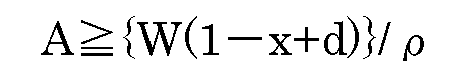
wherein,W is a water-section height (m) (about 10 m) under vacuum;x (atm) is a pressure (atm) applied to the inside of the fluid storage tank;d (atm) is a difference in pressure (atm) in which a pressure (atm) at the bottom of the enclosed pressure-resistant jacket is subtracted from the pressure x (atm) within the fluid storage tank, wherein d>0;ρ is a specific density of the cooling or heating medium,wherein the relation among the height A (m), a height B(m) of the enclosed pressure-resistant jacket from the bottom to the top thereof, and a suction height C(m) of the cooling or heating medium by means of the suction pump satisfies the following equation: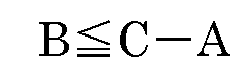
wherein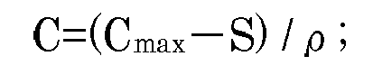 Cmax (m) is a maximum suction height (m) of the cooling or heating medium by the suction pump, provided that the Cmax is a suction height when the cooling or heating medium is deemed as water;S(m) is a safe operational value (m) and is larger than 0 (S>0); andρ and A are as defined above,whereby the cooling or heating medium is allowed to flow in the enclosed pressure-resistant jacket at a pressure lower than the pressure x (atm).
 - The plant according to claim 4, which comprises(a) an enclosed pressure-resistant jacket for allowing the cooling or heating medium to flow and circulate therein, said jacket being provided around the outer wall of the fluid storage tank;(b) a cooling or heating medium-storage tank having a vent and connected at it's one end to the enclosed pressure-resistant jacket via conduit line;(c) a suction pump connected at it's one end to the exit of the cooling or heating medium in the enclosed pressure-resistant jacket and connected at the other end to the cooling or heating medium-storage tank via conduit line; and(d) a pressure-reduction unit connected at it's one end to the bottom of the enclosed pressure-resistant jacket via conduit line and at it's other end to the cooling or heating medium-storage tank via conduit line,
wherein a height B (m) from the bottom of the enclosed pressure-resistant jacket to the top thereof is set to satisfy the following equation: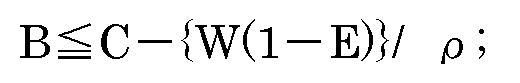
wherein, normal pressure is deemed as 1 atm,
C (m) is a suction height (m) of the cooling or heating medium by the suction pump and
wherein,Cmax (m) is a maximum suction height (m) of water by the suction pump, provided that the Cmax is a suction height when the cooling or heating medium is water;S(m) is a safe operational value (m) and is larger than 0 (S>0);ρ is a specific density of the cooling or heating mediumW (m) is a water-section height (m) (about 10 m) under vacuum;E (atm) is a pressure (atm) set at the pressure-reduction unit, wherein, x (atm) is a pressure (atm) applied to the inside of the fluid storage tank;d (atm) is a pressure difference (atm) in which a pressure (atm) at the bottom of the enclosed pressure-resistant jacket is subtracted from the pressure x (atm) within the fluid storage tank, which difference is required when the suction pump is stopped, wherein d>0,whereby the cooling or heating medium is allowed to flow in the enclosed pressure-resistant jacket at a pressure lower than the pressure x (atm).
 - The plant according to claim 5 or 6, wherein the pressure difference d (atm) is in a range from 0.2 to 0.4 (atm).
- The plant according to any one of claims 4 to 7, wherein the fluid storage tank is a larger size tank having the height B (m) exceeding the height C (m) of the suction height (m) of the cooling or heating medium by the suction pump, the enclosed pressure-resistant jacket has a multistage construction with not less than 2 staged enclosed pressure-resistant jackets, said first stage having the structure of the enclosed pressure-resistant jacket according to claim 5 or 6, each of the second and subsequent stages being provided with (i) an enclosed pressure-resistant jacket and (ii) a cooling or heating medium-supplying server tank provided separately from the fluid storage tank or a pressure reduction unit and arranged between the cooling or heating medium-storage tank and the bottom of each enclosed pressure-resistant jacket,
wherein in the case where the server tank is provided, the height A' from the liquid level of each of the server tank to the bottom of each enclosed pressure-resistant jacket is set to satisfy the following equation:
(wherein W, x, d and ρ are as defined above), and a height A'+B' (m) from the liquid level of each server tank to the top of each enclosed pressure-resistant jacket is set to satisfy the following equation:
(wherein C= (Cmax - S) / ρ, and Cmax, S and ρ are as defined above), and in the case where the pressure reduction unit is provided, the height B' from the bottom of each enclosed pressure-resistant jacket to the top thereof is set to satisfy the following equation:
(wherein C, W, E and ρ are as defined above). - The plant according any one of claims 4 to 8, wherein an air pool for sampling the cooling or heating medium is provided in a passage of the cooling or heating medium to analyze the components of the cooling or heating medium.
- A pressure reduction unit comprising a pressure-reducing valve for reducing a pressurized cooling or heating medium and maintaining it at a constant pressure, and a pressure differential valve for further reducing the pressure of the cooling or heating medium, wherein said pressure reduction unit is used in a plant for preventing contamination of a fluid in a fluid storage tank with a liquid cooling or heating medium flowing in an enclosed pressure-resistant jacket provided around the outer wall of the fluid storage tank, wherein said contamination is caused by damage of a wall of the fluid storage tank and is prevented by allowing the cooling or heating medium to flow in the enclosed pressure-resistant jacket at a pressure lower than the pressure x (atm) applied within the fluid storage tank,
wherein said plant in which contamination of the fluid is prevented comprises(a)an enclosed pressure-resistant jacket for allowing the cooling or heating medium to flow and circulating therein, said jacket being provided around the outer wall of the fluid storage tank;(b)a cooling or heating medium-storage tank having a vent and connected at it's one end to the enclosed pressure-resistant jacket via conduit line;(c)a suction pump connected at it's one end to the exit of the cooling or heating medium in the enclosed pressure-resistant jacket and connected at the other end to the cooling or heating medium-storage tank via conduit line; and(d)a pressure-reduction unit connected at it's one end to the bottom of the enclosed pressure-resistant jacket via conduit line and at it's other end to the cooling or heating medium-storage tank via conduit line,wherein a height B (m) from the bottom of the enclosed pressure-resistant jacket to the top thereof is set to satisfy the following equation:
wherein, normal pressure is deemed as 1 atm,
C (m) is a suction height (m) of the cooling or heating medium by the suction pump and
wherein,Cmax (m) is a maximum suction height (m) of water by the suction pump, provided that the Cmax is a suction height when the cooling or heating medium is water;S(m) is a safe operational value (m) and is larger than 0 (S>0);ρ is a specific density of the cooling or heating mediumW (m) is a water-section height (m) (about 10 m) under vacuum;E (atm) is a pressure (atm) set at the pressure-reduction unit, wherein, x (atm) is a pressure (atm) applied to the inside of the fluid storage tank;d (atm) is a difference in pressure (atm) in which a pressure (atm) at the bottom of the enclosed pressure-resistant jacket is subtracted from the pressure x (atm) within the fluid storage tank, which difference is required when the suction pump is stopped, wherein d>0.
 - A method for detecting cracks of a fluid storage tank in which the temperature of a fluid in said fluid storage tank is controlled by allowing a liquid cooling or heating medium to flow in an enclosed pressure-resistant jacket provided around the outer wall of the fluid storage tank under a predetermined pressure which comprises allowing the liquid cooling or heating medium to flow in the enclosed pressure-resistant jacket at a pressure lower than the pressure x (atm) applied within the fluid storage tank, sampling the cooling or heating medium from an air pool provided in a passage of the cooling or heating medium, and analyzing the components of the cooling or heating medium, while preventing contamination of the fluid in the fluid storage tank with the liquid cooling or heating medium.
- The method according to any one of claims 1 to 3, wherein a space in which the cooling or heating medium flows is physically and forcibly reduced in pressure while stopping the flow of the cooling or heating medium and sealing the space.
- The plant according to any one of claims 4 to 8, which further comprise a physically pressure-reducing apparatus for physically and forcibly reducing the pressure in a space in which the cooling or heating medium flows, while stopping the flow of the cooling or heating medium and sealing the space.
Applications Claiming Priority (2)
| Application Number | Priority Date | Filing Date | Title |
|---|---|---|---|
| JP2010092479A JP4707764B1 (en) | 2010-04-13 | 2010-04-13 | Method and apparatus for preventing contamination in a fluid storage tank requiring temperature control |
| PCT/JP2011/059031 WO2011129306A1 (en) | 2010-04-13 | 2011-04-11 | Method for contamination prevention in fluid storage tank requiring temperature control, and device therefor |
Publications (3)
| Publication Number | Publication Date |
|---|---|
| EP2559637A1 true EP2559637A1 (en) | 2013-02-20 |
| EP2559637A4 EP2559637A4 (en) | 2015-07-01 |
| EP2559637B1 EP2559637B1 (en) | 2017-09-06 |
Family
ID=44292610
Family Applications (1)
| Application Number | Title | Priority Date | Filing Date |
|---|---|---|---|
| EP11768827.5A Not-in-force EP2559637B1 (en) | 2010-04-13 | 2011-04-11 | Method for contamination prevention in fluid storage tank requiring temperature control, and device therefor |
Country Status (12)
| Country | Link |
|---|---|
| US (3) | US9248480B2 (en) |
| EP (1) | EP2559637B1 (en) |
| JP (1) | JP4707764B1 (en) |
| KR (1) | KR101821434B1 (en) |
| CN (1) | CN102985342B (en) |
| AU (1) | AU2011242003B2 (en) |
| BR (1) | BR112012025924B1 (en) |
| CA (1) | CA2795434C (en) |
| ES (1) | ES2642279T3 (en) |
| MX (1) | MX2012011683A (en) |
| RU (1) | RU2564583C2 (en) |
| WO (1) | WO2011129306A1 (en) |
Cited By (1)
| Publication number | Priority date | Publication date | Assignee | Title |
|---|---|---|---|---|
| CN111186650A (en) * | 2020-01-16 | 2020-05-22 | 海口海关技术中心 | Transfer storage tank with dampproofing fresh-keeping thermal-insulated function |
Families Citing this family (4)
| Publication number | Priority date | Publication date | Assignee | Title |
|---|---|---|---|---|
| NL2009749C2 (en) | 2012-11-02 | 2014-05-06 | Eeuwe Durk Kooi | TANK CONTAINER. |
| US10788269B2 (en) * | 2016-11-07 | 2020-09-29 | Wabash National, L.P. | Cooling system for mobile bulk tanks |
| CN113859787B (en) * | 2021-09-03 | 2023-03-21 | 中建材创新科技研究院有限公司 | Controllable gypsum feed bin of material temperature |
| CN116395288B (en) * | 2023-05-22 | 2025-11-18 | 上海泓济环保科技股份有限公司 | Zero-emission evaporation mother liquor automatic constant temperature storage equipment |
Family Cites Families (24)
| Publication number | Priority date | Publication date | Assignee | Title |
|---|---|---|---|---|
| US1987917A (en) * | 1933-02-04 | 1935-01-15 | Heil Co | Refrigerated tank |
| US2434956A (en) * | 1945-11-05 | 1948-01-27 | Spencer S Prentiss | Liquid oxygen "walkaround" unit |
| US3143167A (en) * | 1961-05-19 | 1964-08-04 | Tung Sol Electric Inc | Temperature controlled enclosure for testing purposes |
| US3451225A (en) * | 1968-02-08 | 1969-06-24 | Daryl G Hill | Water-jacket warmer for stationary fuel tank |
| US4298060A (en) * | 1979-02-14 | 1981-11-03 | Elliott Turbomachinery Limited | Fluid jacket for a vessel |
| US4261415A (en) * | 1979-10-19 | 1981-04-14 | Autoclave Engineers, Inc. | Method and apparatus for cooling a pressure vessel |
| US4502531A (en) * | 1983-02-28 | 1985-03-05 | Allied Corporation | High-pressure vessel furnace |
| DE3643557A1 (en) | 1986-12-19 | 1988-06-23 | Westerwaelder Eisen Gerhard | TEMPERATURE TANK CONTAINER |
| US4882912A (en) | 1988-10-12 | 1989-11-28 | Container Design Limited | Temperature controllable tank container |
| US5170659A (en) * | 1991-04-08 | 1992-12-15 | Kemp Development Corporation | Apparatus and method for detecting fluid leakage |
| US5552039A (en) * | 1994-07-13 | 1996-09-03 | Rpc Waste Management Services, Inc. | Turbulent flow cold-wall reactor |
| JP3593406B2 (en) | 1995-12-15 | 2004-11-24 | 株式会社テイエルブイ | Decompression heating and cooling equipment |
| US5743023A (en) * | 1996-09-06 | 1998-04-28 | Fay; John M. | Method and apparatus for controlling freeze drying process |
| US6610250B1 (en) * | 1999-08-23 | 2003-08-26 | 3M Innovative Properties Company | Apparatus using halogenated organic fluids for heat transfer in low temperature processes requiring sterilization and methods therefor |
| JP2001088894A (en) * | 1999-09-21 | 2001-04-03 | Nihon Tetra Pak Kk | Tank equipment |
| JP3587513B2 (en) | 2001-04-26 | 2004-11-10 | 株式会社ロッコーエンジニアリング | Cooling tank |
| CN1417527A (en) * | 2001-11-02 | 2003-05-14 | 量子能技术股份有限公司 | Improved water heater |
| JP2004316992A (en) | 2003-04-15 | 2004-11-11 | Tlv Co Ltd | Indirect heat exchanger |
| US7870891B2 (en) * | 2004-05-29 | 2011-01-18 | Kilr-Chilr, Llc | Systems, devices and methods for regulating temperatures of tanks, containers and contents therein |
| JP4068108B2 (en) * | 2005-11-04 | 2008-03-26 | 大陽日酸株式会社 | Heating medium heating and cooling device |
| CN2851175Y (en) * | 2005-11-23 | 2006-12-27 | 中国石油天然气股份有限公司 | Temperature and pressure self-controlled natural gas heating oil storage tank device in beach oil field |
| US7832466B2 (en) * | 2006-11-29 | 2010-11-16 | Abdullah Ahmad Al-Hashash | Water supply system |
| KR100857551B1 (en) | 2007-03-07 | 2008-09-09 | 세메스 주식회사 | Liquid supply |
| JP2009293844A (en) | 2008-06-04 | 2009-12-17 | Chugoku Electric Power Co Inc:The | High-viscosity liquid fuel warming system |
-
2010
- 2010-04-13 JP JP2010092479A patent/JP4707764B1/en active Active
-
2011
- 2011-04-11 US US13/641,407 patent/US9248480B2/en active Active
- 2011-04-11 AU AU2011242003A patent/AU2011242003B2/en not_active Ceased
- 2011-04-11 BR BR112012025924-5A patent/BR112012025924B1/en not_active IP Right Cessation
- 2011-04-11 KR KR1020127029644A patent/KR101821434B1/en not_active Expired - Fee Related
- 2011-04-11 WO PCT/JP2011/059031 patent/WO2011129306A1/en not_active Ceased
- 2011-04-11 CN CN201180019114.5A patent/CN102985342B/en active Active
- 2011-04-11 CA CA2795434A patent/CA2795434C/en not_active Expired - Fee Related
- 2011-04-11 MX MX2012011683A patent/MX2012011683A/en active IP Right Grant
- 2011-04-11 RU RU2012148126/12A patent/RU2564583C2/en not_active IP Right Cessation
- 2011-04-11 EP EP11768827.5A patent/EP2559637B1/en not_active Not-in-force
- 2011-04-11 ES ES11768827.5T patent/ES2642279T3/en active Active
-
2015
- 2015-12-22 US US14/978,043 patent/US10058903B2/en active Active
-
2018
- 2018-07-25 US US16/045,261 patent/US10562082B2/en active Active
Cited By (1)
| Publication number | Priority date | Publication date | Assignee | Title |
|---|---|---|---|---|
| CN111186650A (en) * | 2020-01-16 | 2020-05-22 | 海口海关技术中心 | Transfer storage tank with dampproofing fresh-keeping thermal-insulated function |
Also Published As
| Publication number | Publication date |
|---|---|
| RU2564583C2 (en) | 2015-10-10 |
| US20160107208A1 (en) | 2016-04-21 |
| US9248480B2 (en) | 2016-02-02 |
| AU2011242003A1 (en) | 2012-10-25 |
| MX2012011683A (en) | 2013-02-21 |
| US10562082B2 (en) | 2020-02-18 |
| KR20130055602A (en) | 2013-05-28 |
| RU2012148126A (en) | 2014-05-20 |
| US20180326463A1 (en) | 2018-11-15 |
| CA2795434A1 (en) | 2011-10-20 |
| US10058903B2 (en) | 2018-08-28 |
| US20130192684A1 (en) | 2013-08-01 |
| KR101821434B1 (en) | 2018-01-23 |
| CN102985342A (en) | 2013-03-20 |
| AU2011242003B2 (en) | 2014-08-07 |
| CA2795434C (en) | 2017-10-17 |
| WO2011129306A1 (en) | 2011-10-20 |
| BR112012025924A2 (en) | 2016-06-28 |
| EP2559637B1 (en) | 2017-09-06 |
| JP2011219148A (en) | 2011-11-04 |
| JP4707764B1 (en) | 2011-06-22 |
| ES2642279T3 (en) | 2017-11-16 |
| CN102985342B (en) | 2015-06-17 |
| EP2559637A4 (en) | 2015-07-01 |
| BR112012025924B1 (en) | 2019-11-19 |
Similar Documents
| Publication | Publication Date | Title |
|---|---|---|
| US10562082B2 (en) | Method for contamination prevention in fluid storage tank requiring temperature control, and device therefor | |
| KR20230104918A (en) | Multi-Rack Immersion Cooling Distribution System | |
| AU2016363679B2 (en) | Fluid cooling system and method for electronics equipment | |
| US11197397B2 (en) | Provisioning data center server cooling equipment | |
| US7413054B2 (en) | Oil circulation retention system and method | |
| US20050126276A1 (en) | Method, system and program product for monitoring rate of volume change of coolant within a cooling system | |
| US20210068303A1 (en) | Leak mitigation in a cooling system for computing devices | |
| US6142748A (en) | Degas piping for pumps | |
| CA2866572C (en) | Method of reducing leaks from a pipeline | |
| EP2535691A1 (en) | Leak isolation logic for closed-volume system | |
| AU2019356968B2 (en) | System and method for separation of air from liquid | |
| CN106941311A (en) | Frequency converter water-cooling control system | |
| GB2502593A (en) | Modular cooler for alcoholic beverages | |
| DE202013010271U1 (en) | Sea vessel with liquefied gas tank | |
| JP2023033348A (en) | seal water tank | |
| RU2657925C1 (en) | Stationary gas-turbine plant oil station | |
| CN117268454A (en) | Oil monitoring box test calibration device |
Legal Events
| Date | Code | Title | Description |
|---|---|---|---|
| PUAI | Public reference made under article 153(3) epc to a published international application that has entered the european phase |
Free format text: ORIGINAL CODE: 0009012 |
|
| 17P | Request for examination filed |
Effective date: 20121003 |
|
| AK | Designated contracting states |
Kind code of ref document: A1 Designated state(s): AL AT BE BG CH CY CZ DE DK EE ES FI FR GB GR HR HU IE IS IT LI LT LU LV MC MK MT NL NO PL PT RO RS SE SI SK SM TR |
|
| XX | Miscellaneous (additional remarks) |
Free format text: THE APPLICANT FILED A TEXT BY WHICH IT IS INTENDED TO BRING THE TRANSLATION INTO CONFORMITY WITH THE ORIGINAL TEXT OF THE APPLICATION (ART.14(2) EPC). |
|
| DAX | Request for extension of the european patent (deleted) | ||
| REG | Reference to a national code |
Ref country code: DE Ref legal event code: R079 Ref document number: 602011041360 Country of ref document: DE Free format text: PREVIOUS MAIN CLASS: B65D0090220000 Ipc: B65D0088740000 |
|
| RA4 | Supplementary search report drawn up and despatched (corrected) |
Effective date: 20150529 |
|
| RIC1 | Information provided on ipc code assigned before grant |
Ipc: B65D 90/50 20060101ALI20150522BHEP Ipc: B65D 88/74 20060101AFI20150522BHEP |
|
| 17Q | First examination report despatched |
Effective date: 20160420 |
|
| STAA | Information on the status of an ep patent application or granted ep patent |
Free format text: STATUS: EXAMINATION IS IN PROGRESS |
|
| GRAP | Despatch of communication of intention to grant a patent |
Free format text: ORIGINAL CODE: EPIDOSNIGR1 |
|
| STAA | Information on the status of an ep patent application or granted ep patent |
Free format text: STATUS: GRANT OF PATENT IS INTENDED |
|
| INTG | Intention to grant announced |
Effective date: 20170404 |
|
| GRAS | Grant fee paid |
Free format text: ORIGINAL CODE: EPIDOSNIGR3 |
|
| GRAA | (expected) grant |
Free format text: ORIGINAL CODE: 0009210 |
|
| STAA | Information on the status of an ep patent application or granted ep patent |
Free format text: STATUS: THE PATENT HAS BEEN GRANTED |
|
| AK | Designated contracting states |
Kind code of ref document: B1 Designated state(s): AL AT BE BG CH CY CZ DE DK EE ES FI FR GB GR HR HU IE IS IT LI LT LU LV MC MK MT NL NO PL PT RO RS SE SI SK SM TR |
|
| REG | Reference to a national code |
Ref country code: GB Ref legal event code: FG4D |
|
| XX | Miscellaneous (additional remarks) |
Free format text: THE APPLICANT FILED A TEXT BY WHICH IT IS INTENDED TO BRING THE TRANSLATION INTO CONFORMITY WITH THE ORIGINAL TEXT OF THE APPLICATION (ART.14(2) EPC). |
|
| REG | Reference to a national code |
Ref country code: CH Ref legal event code: EP Ref country code: AT Ref legal event code: REF Ref document number: 925627 Country of ref document: AT Kind code of ref document: T Effective date: 20170915 |
|
| REG | Reference to a national code |
Ref country code: IE Ref legal event code: FG4D |
|
| REG | Reference to a national code |
Ref country code: DE Ref legal event code: R096 Ref document number: 602011041360 Country of ref document: DE |
|
| REG | Reference to a national code |
Ref country code: NL Ref legal event code: FP |
|
| REG | Reference to a national code |
Ref country code: ES Ref legal event code: FG2A Ref document number: 2642279 Country of ref document: ES Kind code of ref document: T3 Effective date: 20171116 |
|
| REG | Reference to a national code |
Ref country code: LT Ref legal event code: MG4D |
|
| PG25 | Lapsed in a contracting state [announced via postgrant information from national office to epo] |
Ref country code: LT Free format text: LAPSE BECAUSE OF FAILURE TO SUBMIT A TRANSLATION OF THE DESCRIPTION OR TO PAY THE FEE WITHIN THE PRESCRIBED TIME-LIMIT Effective date: 20170906 Ref country code: HR Free format text: LAPSE BECAUSE OF FAILURE TO SUBMIT A TRANSLATION OF THE DESCRIPTION OR TO PAY THE FEE WITHIN THE PRESCRIBED TIME-LIMIT Effective date: 20170906 Ref country code: SE Free format text: LAPSE BECAUSE OF FAILURE TO SUBMIT A TRANSLATION OF THE DESCRIPTION OR TO PAY THE FEE WITHIN THE PRESCRIBED TIME-LIMIT Effective date: 20170906 Ref country code: NO Free format text: LAPSE BECAUSE OF FAILURE TO SUBMIT A TRANSLATION OF THE DESCRIPTION OR TO PAY THE FEE WITHIN THE PRESCRIBED TIME-LIMIT Effective date: 20171206 Ref country code: FI Free format text: LAPSE BECAUSE OF FAILURE TO SUBMIT A TRANSLATION OF THE DESCRIPTION OR TO PAY THE FEE WITHIN THE PRESCRIBED TIME-LIMIT Effective date: 20170906 |
|
| REG | Reference to a national code |
Ref country code: AT Ref legal event code: MK05 Ref document number: 925627 Country of ref document: AT Kind code of ref document: T Effective date: 20170906 |
|
| PG25 | Lapsed in a contracting state [announced via postgrant information from national office to epo] |
Ref country code: BG Free format text: LAPSE BECAUSE OF FAILURE TO SUBMIT A TRANSLATION OF THE DESCRIPTION OR TO PAY THE FEE WITHIN THE PRESCRIBED TIME-LIMIT Effective date: 20171206 Ref country code: GR Free format text: LAPSE BECAUSE OF FAILURE TO SUBMIT A TRANSLATION OF THE DESCRIPTION OR TO PAY THE FEE WITHIN THE PRESCRIBED TIME-LIMIT Effective date: 20171207 Ref country code: RS Free format text: LAPSE BECAUSE OF FAILURE TO SUBMIT A TRANSLATION OF THE DESCRIPTION OR TO PAY THE FEE WITHIN THE PRESCRIBED TIME-LIMIT Effective date: 20170906 Ref country code: LV Free format text: LAPSE BECAUSE OF FAILURE TO SUBMIT A TRANSLATION OF THE DESCRIPTION OR TO PAY THE FEE WITHIN THE PRESCRIBED TIME-LIMIT Effective date: 20170906 |
|
| REG | Reference to a national code |
Ref country code: FR Ref legal event code: PLFP Year of fee payment: 8 |
|
| PG25 | Lapsed in a contracting state [announced via postgrant information from national office to epo] |
Ref country code: RO Free format text: LAPSE BECAUSE OF FAILURE TO SUBMIT A TRANSLATION OF THE DESCRIPTION OR TO PAY THE FEE WITHIN THE PRESCRIBED TIME-LIMIT Effective date: 20170906 Ref country code: PL Free format text: LAPSE BECAUSE OF FAILURE TO SUBMIT A TRANSLATION OF THE DESCRIPTION OR TO PAY THE FEE WITHIN THE PRESCRIBED TIME-LIMIT Effective date: 20170906 Ref country code: CZ Free format text: LAPSE BECAUSE OF FAILURE TO SUBMIT A TRANSLATION OF THE DESCRIPTION OR TO PAY THE FEE WITHIN THE PRESCRIBED TIME-LIMIT Effective date: 20170906 |
|
| PG25 | Lapsed in a contracting state [announced via postgrant information from national office to epo] |
Ref country code: EE Free format text: LAPSE BECAUSE OF FAILURE TO SUBMIT A TRANSLATION OF THE DESCRIPTION OR TO PAY THE FEE WITHIN THE PRESCRIBED TIME-LIMIT Effective date: 20170906 Ref country code: AT Free format text: LAPSE BECAUSE OF FAILURE TO SUBMIT A TRANSLATION OF THE DESCRIPTION OR TO PAY THE FEE WITHIN THE PRESCRIBED TIME-LIMIT Effective date: 20170906 Ref country code: IS Free format text: LAPSE BECAUSE OF FAILURE TO SUBMIT A TRANSLATION OF THE DESCRIPTION OR TO PAY THE FEE WITHIN THE PRESCRIBED TIME-LIMIT Effective date: 20180106 Ref country code: SK Free format text: LAPSE BECAUSE OF FAILURE TO SUBMIT A TRANSLATION OF THE DESCRIPTION OR TO PAY THE FEE WITHIN THE PRESCRIBED TIME-LIMIT Effective date: 20170906 Ref country code: SM Free format text: LAPSE BECAUSE OF FAILURE TO SUBMIT A TRANSLATION OF THE DESCRIPTION OR TO PAY THE FEE WITHIN THE PRESCRIBED TIME-LIMIT Effective date: 20170906 |
|
| REG | Reference to a national code |
Ref country code: DE Ref legal event code: R097 Ref document number: 602011041360 Country of ref document: DE |
|
| PLBE | No opposition filed within time limit |
Free format text: ORIGINAL CODE: 0009261 |
|
| STAA | Information on the status of an ep patent application or granted ep patent |
Free format text: STATUS: NO OPPOSITION FILED WITHIN TIME LIMIT |
|
| PG25 | Lapsed in a contracting state [announced via postgrant information from national office to epo] |
Ref country code: DK Free format text: LAPSE BECAUSE OF FAILURE TO SUBMIT A TRANSLATION OF THE DESCRIPTION OR TO PAY THE FEE WITHIN THE PRESCRIBED TIME-LIMIT Effective date: 20170906 |
|
| 26N | No opposition filed |
Effective date: 20180607 |
|
| PG25 | Lapsed in a contracting state [announced via postgrant information from national office to epo] |
Ref country code: SI Free format text: LAPSE BECAUSE OF FAILURE TO SUBMIT A TRANSLATION OF THE DESCRIPTION OR TO PAY THE FEE WITHIN THE PRESCRIBED TIME-LIMIT Effective date: 20170906 |
|
| PG25 | Lapsed in a contracting state [announced via postgrant information from national office to epo] |
Ref country code: MC Free format text: LAPSE BECAUSE OF FAILURE TO SUBMIT A TRANSLATION OF THE DESCRIPTION OR TO PAY THE FEE WITHIN THE PRESCRIBED TIME-LIMIT Effective date: 20170906 |
|
| PG25 | Lapsed in a contracting state [announced via postgrant information from national office to epo] |
Ref country code: LU Free format text: LAPSE BECAUSE OF NON-PAYMENT OF DUE FEES Effective date: 20180411 |
|
| PGFP | Annual fee paid to national office [announced via postgrant information from national office to epo] |
Ref country code: NL Payment date: 20190416 Year of fee payment: 9 |
|
| PGFP | Annual fee paid to national office [announced via postgrant information from national office to epo] |
Ref country code: IT Payment date: 20190418 Year of fee payment: 9 Ref country code: ES Payment date: 20190520 Year of fee payment: 9 Ref country code: IE Payment date: 20190426 Year of fee payment: 9 Ref country code: DE Payment date: 20190418 Year of fee payment: 9 |
|
| PGFP | Annual fee paid to national office [announced via postgrant information from national office to epo] |
Ref country code: FR Payment date: 20190416 Year of fee payment: 9 Ref country code: BE Payment date: 20190416 Year of fee payment: 9 |
|
| PGFP | Annual fee paid to national office [announced via postgrant information from national office to epo] |
Ref country code: CH Payment date: 20190416 Year of fee payment: 9 |
|
| PGFP | Annual fee paid to national office [announced via postgrant information from national office to epo] |
Ref country code: GB Payment date: 20190425 Year of fee payment: 9 |
|
| PG25 | Lapsed in a contracting state [announced via postgrant information from national office to epo] |
Ref country code: MT Free format text: LAPSE BECAUSE OF NON-PAYMENT OF DUE FEES Effective date: 20180411 |
|
| PG25 | Lapsed in a contracting state [announced via postgrant information from national office to epo] |
Ref country code: TR Free format text: LAPSE BECAUSE OF FAILURE TO SUBMIT A TRANSLATION OF THE DESCRIPTION OR TO PAY THE FEE WITHIN THE PRESCRIBED TIME-LIMIT Effective date: 20170906 |
|
| PG25 | Lapsed in a contracting state [announced via postgrant information from national office to epo] |
Ref country code: HU Free format text: LAPSE BECAUSE OF FAILURE TO SUBMIT A TRANSLATION OF THE DESCRIPTION OR TO PAY THE FEE WITHIN THE PRESCRIBED TIME-LIMIT; INVALID AB INITIO Effective date: 20110411 Ref country code: PT Free format text: LAPSE BECAUSE OF FAILURE TO SUBMIT A TRANSLATION OF THE DESCRIPTION OR TO PAY THE FEE WITHIN THE PRESCRIBED TIME-LIMIT Effective date: 20170906 |
|
| PG25 | Lapsed in a contracting state [announced via postgrant information from national office to epo] |
Ref country code: CY Free format text: LAPSE BECAUSE OF FAILURE TO SUBMIT A TRANSLATION OF THE DESCRIPTION OR TO PAY THE FEE WITHIN THE PRESCRIBED TIME-LIMIT Effective date: 20170906 Ref country code: MK Free format text: LAPSE BECAUSE OF NON-PAYMENT OF DUE FEES Effective date: 20170906 |
|
| PG25 | Lapsed in a contracting state [announced via postgrant information from national office to epo] |
Ref country code: AL Free format text: LAPSE BECAUSE OF FAILURE TO SUBMIT A TRANSLATION OF THE DESCRIPTION OR TO PAY THE FEE WITHIN THE PRESCRIBED TIME-LIMIT Effective date: 20170906 |
|
| REG | Reference to a national code |
Ref country code: DE Ref legal event code: R119 Ref document number: 602011041360 Country of ref document: DE |
|
| REG | Reference to a national code |
Ref country code: CH Ref legal event code: PL |
|
| REG | Reference to a national code |
Ref country code: NL Ref legal event code: MM Effective date: 20200501 |
|
| PG25 | Lapsed in a contracting state [announced via postgrant information from national office to epo] |
Ref country code: FR Free format text: LAPSE BECAUSE OF NON-PAYMENT OF DUE FEES Effective date: 20200430 Ref country code: LI Free format text: LAPSE BECAUSE OF NON-PAYMENT OF DUE FEES Effective date: 20200430 Ref country code: DE Free format text: LAPSE BECAUSE OF NON-PAYMENT OF DUE FEES Effective date: 20201103 Ref country code: CH Free format text: LAPSE BECAUSE OF NON-PAYMENT OF DUE FEES Effective date: 20200430 |
|
| REG | Reference to a national code |
Ref country code: BE Ref legal event code: MM Effective date: 20200430 |
|
| PG25 | Lapsed in a contracting state [announced via postgrant information from national office to epo] |
Ref country code: BE Free format text: LAPSE BECAUSE OF NON-PAYMENT OF DUE FEES Effective date: 20200430 |
|
| GBPC | Gb: european patent ceased through non-payment of renewal fee |
Effective date: 20200411 |
|
| PG25 | Lapsed in a contracting state [announced via postgrant information from national office to epo] |
Ref country code: NL Free format text: LAPSE BECAUSE OF NON-PAYMENT OF DUE FEES Effective date: 20200501 |
|
| PG25 | Lapsed in a contracting state [announced via postgrant information from national office to epo] |
Ref country code: GB Free format text: LAPSE BECAUSE OF NON-PAYMENT OF DUE FEES Effective date: 20200411 Ref country code: IE Free format text: LAPSE BECAUSE OF NON-PAYMENT OF DUE FEES Effective date: 20200411 |
|
| REG | Reference to a national code |
Ref country code: ES Ref legal event code: FD2A Effective date: 20210902 |
|
| PG25 | Lapsed in a contracting state [announced via postgrant information from national office to epo] |
Ref country code: IT Free format text: LAPSE BECAUSE OF NON-PAYMENT OF DUE FEES Effective date: 20200411 |
|
| PG25 | Lapsed in a contracting state [announced via postgrant information from national office to epo] |
Ref country code: ES Free format text: LAPSE BECAUSE OF NON-PAYMENT OF DUE FEES Effective date: 20200412 |