EP2559332B2 - Landwirtschaftliche Verteilmaschine - Google Patents
Landwirtschaftliche Verteilmaschine Download PDFInfo
- Publication number
- EP2559332B2 EP2559332B2 EP12401167.7A EP12401167A EP2559332B2 EP 2559332 B2 EP2559332 B2 EP 2559332B2 EP 12401167 A EP12401167 A EP 12401167A EP 2559332 B2 EP2559332 B2 EP 2559332B2
- Authority
- EP
- European Patent Office
- Prior art keywords
- distributor
- boom
- distributor boom
- loop control
- control device
- Prior art date
- Legal status (The legal status is an assumption and is not a legal conclusion. Google has not performed a legal analysis and makes no representation as to the accuracy of the status listed.)
- Active
Links
- 230000001133 acceleration Effects 0.000 claims description 19
- 238000013016 damping Methods 0.000 claims description 10
- 238000005259 measurement Methods 0.000 claims description 4
- 238000000034 method Methods 0.000 claims description 4
- 239000000725 suspension Substances 0.000 claims description 3
- 230000006978 adaptation Effects 0.000 claims description 2
- 238000011156 evaluation Methods 0.000 claims description 2
- 230000005484 gravity Effects 0.000 description 3
- 230000008878 coupling Effects 0.000 description 2
- 238000010168 coupling process Methods 0.000 description 2
- 238000005859 coupling reaction Methods 0.000 description 2
- 238000010586 diagram Methods 0.000 description 2
- 230000005540 biological transmission Effects 0.000 description 1
- 238000001514 detection method Methods 0.000 description 1
Images


Classifications
-
- A—HUMAN NECESSITIES
- A01—AGRICULTURE; FORESTRY; ANIMAL HUSBANDRY; HUNTING; TRAPPING; FISHING
- A01M—CATCHING, TRAPPING OR SCARING OF ANIMALS; APPARATUS FOR THE DESTRUCTION OF NOXIOUS ANIMALS OR NOXIOUS PLANTS
- A01M7/00—Special adaptations or arrangements of liquid-spraying apparatus for purposes covered by this subclass
- A01M7/005—Special arrangements or adaptations of the spraying or distributing parts, e.g. adaptations or mounting of the spray booms, mounting of the nozzles, protection shields
- A01M7/0053—Mounting of the spraybooms
- A01M7/0057—Mounting of the spraybooms with active regulation of the boom position
Definitions
- the invention relates to an agricultural distributing machine according to the preamble of claim 1.
- Such an agricultural distributor is through the DE 10 2007 025 751 A1 known.
- the distribution linkage is to be kept in as quiet a position as possible by compensating for the transmission of the frame movement to the distribution linkage by means of suitable actuators, with sensors detecting the movement of the frame and transmitting it to an electronic control device, which then controls the actuators.
- suitable actuators with sensors detecting the movement of the frame and transmitting it to an electronic control device, which then controls the actuators.
- no accelerations caused by cornering that have an influence on the boom movement are taken into account.
- the linkage has the disadvantageous tendency to incline downward on the inside of the curve.
- the invention is based on the object of being able to determine data in a simple manner in order to avoid a disadvantageous deflection of the distributor rod when cornering or when turning.
- the sensor determining operating data is designed as a rotation rate sensor that, on the basis of the measurement data determined by the rotation rate sensor, the damping element and / or the actuator for influencing the position of the distributor linkage can be controlled and / or adjusted in such a way that the forces acting on the distributor linkage when cornering and / or turning are counteracted.
- the centrifugal acceleration can be determined by means of the rotation rate sensor while cornering or when turning. This is done in that the centrifugal acceleration is calculated using the rotational speed determined by the yaw rate sensor and the actual driving speed. Based on the determined centrifugal acceleration, an adaptation of the boom control is carried out via the control device. This happens before the linkage is deflected from the target position by centrifugal acceleration.
- the centrifugal acceleration acting on the vehicle is determined with the aid of the data from the rotation rate sensor and the driving speed of the vehicle, and the forces acting on the distributor linkage when cornering are calculated on the basis of this acceleration. These calculated data serve as the basis for controlling the actuators in order to keep the distributor linkage in the desired position.
- the damping element and / or the actuator for influencing the position of the distributor boom can be controlled by the control device in accordance with this stored data in such a way that the boom position of the boom is as quiet as possible Distributor linkage when cornering and / or turning is accessible.
- the agricultural distributing machine designed as a drawn agricultural field sprayer 1 is coupled to an agricultural tractor 2 via a coupling device.
- the field sprayer 1 On its rear side, the field sprayer 1 has a distributor linkage 3, which is arranged adjustable in height via a coupling device 4 on the rear end of the frame 5 of the field sprayer 1.
- the distributor rod 3 consists of a central rod section 6 and several rod sections 7, 7 ', 8, 8', 9, 9 'connected to one another in an articulated manner.
- the respective innermost rod section 7, 7 ′ is arranged in an articulated manner on the central rod section 6.
- motorized adjusting elements 10 which are designed here as double-acting hydraulic cylinders, are used the rod sections 7, 7 ', 8, 8', 9, 9 'in a first folding position, which is the working position according to Fig. 1 and in a second folded position, in which the mutually foldable rod sections are arranged in a folded manner, which corresponds to the transport position, not shown.
- the individual rod sections 7, 7 ′, 8, 8 ′, 9, 9 ′ that adjoin one another are connected to one another via joints 11.
- the middle linkage section 6 is pivotable on the frame 5 of the field sprayer 1 via the hinge bracket 12 by means of a hinge pin 13 attached to the pivot axis 14 running in the direction of travel. Furthermore, an intermediate element 15 is also pivotably attached to the hinge pin 13. An adjusting element designed as a double-acting hydraulic cylinder 16 is fastened between the lower end of the intermediate element 15 and the central rod section 6. By means of the hydraulic cylinder 16, the intermediate element 15 and the distributor linkage 3 are connected to one another in a fixed manner.
- the actuators 17 or damping elements for influencing the position of the distributor rod 3 and the spring elements designed as tension springs 18 are arranged between the frame 5 and the intermediate element 15, and thus the distributor linkage 3.
- a rotation rate sensor 19 is assigned to the agricultural distributing machine 1. This rotation rate sensor can also be arranged on the tractor 2 that pulls or carries the distributing machine. The rotation rate sensor 19 transmits the data measured by it to the electronic control device 20. A control and / or evaluation program is stored in the memory of the electronic control device 20. The data that the rotation rate sensor 19 determines are fed to this control and / or evaluation program. On the basis of the measurement data determined by the rotation rate sensor 19, the damping element and / or the actuator 17 for influencing the position of the distributor linkage 3 are controlled and adjusted in accordance with the setting data determined by the control and / or evaluation program. This takes place in such a way that the forces acting on the distributor linkage 3 during cornering and / or the turning process are counteracted.
- the damping element and / or the actuator 17 for influencing the position of the distributor linkage 3 can be controlled by the control device 20 in such a way that the quietest and most stable position possible of the distributor linkage 3 is achieved when cornering and / or turning.
- a rotation rate sensor 20 is used to determine the centrifugal acceleration while the tractor 2 is cornering with the crop protection sprayer 1 and, based on this variable, the boom control is adjusted before the boom 3 is deflected from the target position by the centrifugal acceleration.
- the centrifugal acceleration aZ acts on the center of gravity SG of the linkage 3 during cornering. This acceleration generates a resulting force Faz which is opposite to the acceleration in its effective direction. Due to the distance x between the center of gravity SG of the linkage 3 and the pivot point 21, the force Faz generates a resulting moment Maz. This moment generates a deflection of the linkage 3 while cornering.
- the centrifugal acceleration is determined while the tractor 2 is cornering with the crop protection sprayer 1.
- the mass of the linkage 3 and the distance between the linkage center of gravity SG and the pivot point 14 of the linkage 3 are known, the size of the resulting moment Maz is determined by the evaluation and control program stored in the on-board computer 20. This information can be used for a control and / or regulation in order to adapt the boom parameters in such a way that the resulting torque Maz is compensated without a deflection of the boom 3. It is thus possible to separate the influences of cornering from the movement of the linkage 3.
- the position of the boom 3 relative to the ground surface is determined by the distance sensors 22, which are arranged in a known manner on the two end regions 21 of the distributor boom 3 and which also transmit their measurement data to the on-board computer 20.
Landscapes
- Life Sciences & Earth Sciences (AREA)
- Engineering & Computer Science (AREA)
- Insects & Arthropods (AREA)
- Pest Control & Pesticides (AREA)
- Wood Science & Technology (AREA)
- Zoology (AREA)
- Environmental Sciences (AREA)
- Catching Or Destruction (AREA)
Description
- Die Erfindung betrifft eine landwirtschaftliche Verteilmaschine gemäß des Oberbegriffes des Patentanspruches 1.
- Eine derartige landwirtschaftliche Verteilmaschine ist durch die
DE 10 2007 025 751 A1 bekannt. Bei dieser Verteilmaschine soll das Verteilergestänge durch kompensieren der Übertragung der Rahmenbewegung auf das Verteilergestänge durch geeignete Aktoren in einer möglichst ruhigen Lage gehalten werden, wobei Sensoren die Bewegung des Rahmens erfassen und an eine elektronische Regeleinrichtung übermitteln, die dann die Aktoren ansteuern. Hierbei werden jedoch keine durch Kurvenfahrt hervorgerufene Beschleunigungen, die Einfluss auf die Gestängebewegung haben, berücksichtigt. Bei Kurvenfahrt hat das Gestänge das nachteilige Bestreben in der Regel sich auf der kurveninneren Seite nach unten zuneigen. - Der Erfindung liegt die Aufgabe zu Grunde, auf einfache Weise Daten ermitteln zu können, um bei Kurvenfahrt oder beim Wendevorgang ein nachteiliges Auslenken des Verteilergestänges zu vermeiden.
- Diese Aufgabe wird erfindungsgemäß dadurch gelöst, dass der Betriebsdaten ermittelnde Sensor als Drehratensensor ausgebildet ist, dass auf der Grundlage der von dem Drehratensensor ermittelten Messdaten das Dämpfungselement und/oder der Aktor zur Beeinflussung der Lage des Verteilergestänges ansteuerbar und/oder einstellbar sind, und zwar derart, dass den bei Kurvenfahrt und/oder Wendevorgang auf das Verteilergestänge einwirkenden Kräften entgegengewirkt wird.
- Infolge dieser Maßnahmen lässt sich mittels des Drehratensensors während einer Kurvenfahrt oder beim Wendevorgang die Zentrifugalbeschleunigung ermitteln. Dies geschieht dadurch, dass anhand der von dem Drehratensensor ermittelten Drehgeschwindigkeit und der tatsächlichen Fahrgeschwindigkeit die Zentrifugalbeschleunigung berechnet wird. Anhand der ermittelten Zentrifugalbeschleunigung wird über die Regeleinrichtung eine Anpassung der Gestängeregelung vorgenommen. Dies geschieht bevor das Gestänge durch die Zentrifugalbeschleunigung aus der Sollposition ausgelenkt wird.
- Mit Hilfe der Daten des Drehratensensors und der Fahrgeschwindigkeit des Fahrzeugs wird die auf das Fahrzeug wirkende Zentrifugalbeschleunigung ermittelt und anhand dieser Beschleunigung die auf das Verteilergestänge einwirkenden Kräfte bei einer Kurvenfahrt berechnet. Diese berechneten Daten dienen als Grundlage zu Ansteuerung der Aktoren, um das Verteilergestänge in der gewünschten Lage zu halten.
- Aufgrund der erfindungsgemäßen Erfassung der Zentrifugalbeschleunigung und der daraus über die Regeleinrichtung abgeleiteten Einstelldaten wird erreicht, dass entsprechend dieser hinterlegten Daten das Dämpfungselement und/oder der Aktor zur Beeinflussung der Lage des Verteilergestänges von der Regeleinrichtung ansteuerbar ist und zwar derart, dass eine möglichst ruhige Gestängelage des Verteilergestänges bei Kurvenfahrt und/oder Wendevorgang erreichbar ist.
- Weitere Einzelheiten der Erfindung sind der Beispielsbeschreibung und den Zeichnungen zu entnehmen. Hierbei zeigen
- Fig. 1
- eine als gezogene Feldspritze mit Verteilergestänge ausgebildete landwirtschaftliche Verteilmaschine in schematischer und perspektivischer Darstellung,
- Fig. 2
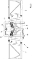
- der mittlere Bereich des Verteilergestänges mit der Aufhängungsvorrichtung des Verteilergestänges am Rahmen der Verteilmaschine in der Ansicht von hinten, in schematischer Darstellung und Teilansicht,
- Fig. 3
- die von einem Ackerschlepper gezogene Feldspritze mit sich Arbeitsstellung befindlichem Verteilergestänge während der Kurvenfahrt und den auf das Gestänge einwirkenden Kräften in Draufsicht und in Prinzipdarstellung und
- Fig. 4
- das Verteilergestänge in der Situation gemäß
Fig. 3 in Rückansicht und mit den auf das Gestänge einwirkenden Kräften in Prinzipdarstellung. - Die als gezogene landwirtschaftliche Feldspritze 1 ausgebildete landwirtschaftliche Verteilmaschine ist über eine Anhängevorrichtung an einen Ackerschlepper 2 angekoppelt. Die Feldspritze 1 weist auf ihrer Rückseite ein Verteilergestänge 3 auf, welches über eine Kuppeleinrichtung 4 an dem rückwärtigen Ende des Rahmens 5 der Feldspritze 1 in Höhenrichtung verstellbar angeordnet ist. Das Verteilergestänge 3 besteht aus einem mittleren Gestängeabschnitt 6 und mehreren gelenkig miteinander verbundenen Gestängeabschnitten 7, 7', 8, 8', 9, 9'. Der jeweilige innerste Gestängeabschnitt 7, 7' ist gelenkig an dem mittleren Gestängeabschnitt 6 angeordnet. Zwischen den einzelnen zueinander einklappbaren Gestängeabschnitten 7, 7', 8, 8', 9, 9' sowie zwischen dem jeweils innersten Gestängeabschnitt 7, 7' und dem mittleren Gestängeabschnitt 6 sind motorischen Stellelemente 10, die hier als doppeltwirkende Hydraulikzylinder ausgebildet sind, zum verbringen der Gestängeabschnitte 7, 7', 8, 8', 9, 9' in eine erste Klappstellung, die der Arbeitsstellung gemäß
Fig. 1 entspricht und in eine zweite Klappstellung, in der die zueinander einklappbaren Gestängeabschnitte in zusammengeklappter Weise, die der nicht dargestellten Transportstellung entspricht, angeordnet. Die einzelnen aneinander anschließenden Gestängeabschnitte 7, 7', 8, 8', 9, 9' sind über Gelenke 11 miteinander verbunden. - Der mittlere Gestängeabschnitt 6 ist über die Gelenkhalterung 12 mittels eines Gelenkbolzens 13 an dem Rahmen 5 der Feldspritze 1 in schwenkbarer Weise um die in Fahrtrichtung verlaufende Schwenkachse 14 befestigt. Weiterhin ist an dem Gelenkbolzen 13 ein Zwischenelement 15 ebenfalls schwenkbar befestigt. Zwischen dem unteren Ende des Zwischenelementes 15 und dem mittleren Gestängeabschnitt 6 ist ein als doppeltwirkender Hydraulikzylinder 16 ausgebildetes Verstellelement befestigt. Mittels des Hydraulikzylinders 16 sind das Zwischenelement 15 und das Verteilergestänge 3 in fester Weise miteinander verbunden.
- Zwischen dem Rahmen 5 und dem Zwischenelement 15, und somit dem Verteilergestänge 3 sind die Aktoren 17 oder Dämpfungselemente zur Beeinflussung der Lage des Verteilergestänges 3 und die als Zugfedern 18 ausgebildeten Federelemente angeordnet.
- Der landwirtschaftlichen Verteilmaschine 1 ist ein Drehratensensor 19 zugeordnet. Dieser Drehratensensor kann auch auf dem die Verteilmaschine ziehenden oder tragenden Ackerschlepper 2 angeordnet sein. Der Drehratensensor 19 übermittelt die von ihm gemessenen Daten an die elektronische Regeleinrichtung 20. In dem Speicher der elektronischen Regeleinrichtung 20 ist ein Steuerungs- und/oder Auswerteprogramm hinterlegt. Diesem Steuerungs- und/oder Auswerteprogramm werden die Daten, die der Drehratensensor 19 ermittelt, zugeführt. Auf der Grundlage der von dem Drehratensensor 19 ermittelten Messdaten werden entsprechend der von dem Steuerungs- und/oder Auswerteprogramm ermittelten Einstelldaten das Dämpfungselement und oder der Aktor 17 zur Beeinflussung der Lage des Verteilergestänges 3 angesteuert und eingestellt. Dieses erfolgt derart, dass den bei Kurvenfahrt und/oder dem Wendevorgang auf das Verteilergestänge 3 einwirkenden Kräften entgegengewirkt wird. Entsprechend der hinterlegten Daten ist das Dämpfungselement und/oder der Aktor 17 zur Beeinflussung der Lage des Verteilergestänges 3 von der Regeleinrichtung 20 ansteuerbar und zwar derart, dass eine möglichst ruhige und stabile Lage des Verteilergestänges 3 bei Kurvenfahrt und/oder dem Wendevorgang erreicht wird.
- Die Ansteuerung der Dämpfungselemente und/oder des Aktors 17 aufgrund der von dem Drehratensensor 19 ermittelten Daten, die von dem in dem Speicher des Bordcomputers 20 hinterlegten Steuerungs- und/oder Auswerteprogramm geschieht im Wesentlichen wie folgt, welches anhand der
Fig. 3 und 4 näher erläutert wird: - Während einer Kurvenfahrt neigt sich das Gestänge 3 einer Pflanzenschutzspritze 1 aufgrund der Zentrifugalbeschleunigung, so dass die kurveninnere Seite des Gestänges 3 nach unten geneigt wird. Mit einem Drehratensensor 20 wird die Zentrifugalbeschleunigung während der Kurvenfahrt des Ackerschleppers 2 mit der Pflanzenschutzspritze 1 ermittelt und anhand dieser Größe eine Anpassung der Gestängeregelung vorgenommen und zwar bevor das Gestänge 3 durch die Zentrifugalbeschleunigung aus der Sollposition ausgelenkt wird. Durch eine entsprechende Anpassung von Dämpfern oder eine Neigungsverstellung des Gestänges 3 durch Aktoren 17, wird somit ein Neigen des Gestänges in einer Kurvenfahrt unterbunden.
- Die Berechnung des gefahrenen Kreisradius (r) anhand der Drehrate (Ω) und der von einem Geschwindigkeitssensor gemessenen Fahrgeschwindigkeit (v) erfolgt nach der mathematischen Gleichung:

- Die Berechnung der Zentrifugalbeschleunigung (az) anhand der von dem Drehratensensor gemessenen Drehrate (Q) und dem Kreisradius (r) erfolgt nach der Gleichung:

- Auf den Schwerpunkt SG des Gestänges 3 wirkt während einer Kurvenfahrt die Zentrifugalbeschleunigung aZ. Diese Beschleunigung erzeugt eine resultierende Kraft Faz die in ihrer Wirkrichtung der Beschleunigung entgegengesetzt ist. Aufgrund des Abstands x zwischen dem Schwerpunkt SG des Gestänges 3 und dem Drehpunkt 21 erzeugt die Kraft Faz ein resultierendes Moment Maz. Dieses Moment erzeugt eine Auslenkung des Gestänges 3 während einer Kurvenfahrt.
- Mit Hilfe eines Drehratensensors 19 wird die Zentrifugalbeschleunigung während einer Kurvenfahrt des Ackerschleppers 2 mit der Pflanzenschutzspritze 1 ermittelt. Sind die Masse des Gestänges 3 und der Abstand zwischen dem Gestängeschwerpunkt SG und dem Drehpunkt 14 des Gestänges 3 bekannt, so wird hieraus die Größe des resultierenden Moments Maz durch das im Bordrechner 20 abgespeicherte Auswerte- und Steuerungsprogramm ermittelt. Diese Information kann für eine Steuerung und/oder Regelung genutzt werden, um die Gestängeparameter dahingehend anzupassen, dass das resultierende Moment Maz, ohne eine Auslenkung des Gestänges 3, kompensiert wird. Somit ist es möglich, Einflüsse von Kurvenfahrten von der Bewegung des Gestänges 3 zu trennen. Die Lage des Gestänges 3 zur Bodenoberfläche wird von den an den beiden Endbereichen 21 des Verteilergestänges 3 in bekannter Weise angeordneten Abstandssensoren 22, die ihre Messdaten ebenfalls an dem Bordcomputer 20 übermitteln, ermittelt.
Claims (2)
- Landwirtschaftliche Verteilmaschine mit Verteilergestänge (3) und einem sich auf einem Fahrwerk auf dem Boden abstützenden Rahmen (5) und zumindest einem Vorratsbehälter, wobei das Verteilergestänge (3) mittels einer Aufhängungsvorrichtung zumindest um eine in Fahrtrichtung zum Verteilergestänge (3) verlaufende Schwenkachse (14) bewegbar am Rahmen aufgehängt ist, wobei das Verteilergestänge (3) eine Erstreckung quer zur Fahrtrichtung aufweist, die ein Vielfaches der Transportbreite der Verteilmaschine ist, wobei die Aufhängungsvorrichtung zumindest ein zwischen dem Verteilergestänge (3) und dem Rahmen angeordnetes Dämpfungselement und/oder zumindest einem Aktor (17) zur Beeinflussung der Lage des Verteilergestänges aufweist, welches von einer elektronischen Regeleinrichtung entsprechend eines von in dem Speicher der Regeleinrichtung hinterlegten Steuerungs- und/oder Auswerteprogramms, dem Daten zumindest eines Betriebsdaten der Verteilmaschine ermittelnden Sensors zugeführt werden, ansteuerbar ist
dadurch gekennzeichnet, dass
der Betriebsdaten ermittelnde Sensor als Drehratensensor (19) zur Ermittlung der Zentrifugalbeschleunigung während einer Kurvenfahrt oder beim Wendevorgang ausgebildet und angeordnet ist, wobei der Drehratensensor (19) die Drehrate Ω der Verteilmaschine bei Kurvenfahrt misst, dass auf der Grundlage der von dem Drehratensensor (19) ermittelten Messdaten das Dämpfungselement und/oder der Aktor (17) zur Beeinflussung der Lage des Verteilergestänges (3) ansteuerbar und/oder einstellbar sind, und zwar derart, dass den bei Kurvenfahrt und/oder Wendevorgang auf das Verteilergestänge (3) einwirkenden Kräften entgegengewirkt wird, wobei anhand der von dem Drehratensensor ermittelten Drehrate Ω und der tatsächlichen Fahrgeschwindigkeit die Zentrifugalbeschleunigung berechnet und anhand der ermittelten Zentrifugalbeschleunigung über die Regeleinrichtung eine Anpassung der Gestängeregelung vorgenommen wird. - Landwirtschaftliche Verteilmaschine nach Anspruch 1,
dadurch gekennzeichnet, dass
entsprechend dieser hinterlegten Daten das Dämpfungselement und/oder der Aktor (17) zur Beeinflussung der Lage des Verteilergestänges (3) von der Regeleinrichtung (20) ansteuerbar ist und zwar derart, dass eine möglichst ruhige Gestängelage des Verteilergestänges (3) bei Kurvenfahrt und/oder Wendevorgang erreichbar ist.
Priority Applications (1)
| Application Number | Priority Date | Filing Date | Title |
|---|---|---|---|
| PL12401167T PL2559332T5 (pl) | 2011-08-15 | 2012-08-08 | Rolnicza maszyna rozdzielająca |
Applications Claiming Priority (1)
| Application Number | Priority Date | Filing Date | Title |
|---|---|---|---|
| DE102011052705A DE102011052705A1 (de) | 2011-08-15 | 2011-08-15 | Landwirtschaftliche Verteilmaschine |
Publications (3)
| Publication Number | Publication Date |
|---|---|
| EP2559332A1 EP2559332A1 (de) | 2013-02-20 |
| EP2559332B1 EP2559332B1 (de) | 2014-12-10 |
| EP2559332B2 true EP2559332B2 (de) | 2021-01-13 |
Family
ID=46796504
Family Applications (1)
| Application Number | Title | Priority Date | Filing Date |
|---|---|---|---|
| EP12401167.7A Active EP2559332B2 (de) | 2011-08-15 | 2012-08-08 | Landwirtschaftliche Verteilmaschine |
Country Status (4)
| Country | Link |
|---|---|
| EP (1) | EP2559332B2 (de) |
| DE (1) | DE102011052705A1 (de) |
| DK (1) | DK2559332T4 (de) |
| PL (1) | PL2559332T5 (de) |
Families Citing this family (13)
| Publication number | Priority date | Publication date | Assignee | Title |
|---|---|---|---|---|
| EP3007553B2 (de) | 2013-09-18 | 2022-12-28 | HORSCH LEEB Application Systems GmbH | Vorrichtung zum ausbringen von flüssigen und/oder festen wirkstoffen und verfahren zur steuerung einer solchen vorrichtung |
| EP3689141A1 (de) * | 2013-10-14 | 2020-08-05 | HORSCH LEEB Application Systems GmbH | Vorrichtung zum ausbringen von flüssigen und/oder festen wirkstoffen und verfahren zur steuerung einer solchen vorrichtung |
| DE102014101866A1 (de) * | 2014-02-14 | 2015-08-20 | Amazonen-Werke H. Dreyer Gmbh & Co. Kg | Feldspritze und Verfahren zum Betreiben einer Feldspritze |
| DE102014207595A1 (de) | 2014-04-23 | 2015-10-29 | Robert Bosch Gmbh | Feldspritze |
| DE102014118606A1 (de) | 2014-12-15 | 2016-06-16 | Amazonen-Werke H. Dreyer Gmbh & Co. Kg | Verteilmaschine |
| DE102015102975A1 (de) * | 2015-03-02 | 2016-09-08 | Horsch Leeb Application Systems Gmbh | Vorrichtung zum Ausbringen von flüssigen und/oder festen Wirkstoffen und Verfahren zur Steuerung einer solchen Vorrichtung |
| DE102015104690A1 (de) * | 2015-03-27 | 2016-09-29 | Amazonen-Werke H. Dreyer Gmbh & Co. Kg | Landwirtschaftliche Maschine und Sicherheitsverfahren |
| GB201508250D0 (en) * | 2015-05-14 | 2015-06-24 | Norac Systems Internat Inc | Control system and method for a suspended boom sprayer |
| DK3141114T3 (en) * | 2015-09-08 | 2018-12-03 | Herbert Dammann Gmbh | Field Spray and Procedure |
| DE102016109513A1 (de) | 2016-05-24 | 2017-11-30 | Amazonen-Werke H. Dreyer Gmbh & Co. Kg | Regel- und/oder Steuersystem, landwirtschaftliche Maschine mit einem solchen System und Verfahren zum Betreiben einer landwirtschaftlichen Maschine |
| DE102017201918A1 (de) | 2017-02-07 | 2018-08-09 | Deere & Company | Landwirtschaftliche Verteilmaschine mit selbsttätiger Kontrolle der Dämpfung des Verteilergestänges |
| DE102019129205A1 (de) | 2019-10-29 | 2021-04-29 | Horsch Leeb Application Systems Gmbh | Landmaschine mit System zur Berechnung eines Geländerelief und Verfahren zum Betreiben einer Landmaschine |
| CN112889442B (zh) * | 2021-01-08 | 2022-06-21 | 青岛农业大学 | 一种实时测量与精准施肥信息标靶机 |
Citations (8)
| Publication number | Priority date | Publication date | Assignee | Title |
|---|---|---|---|---|
| EP0077270A2 (de) † | 1981-10-09 | 1983-04-20 | Centre National Du Machinisme Agricole, Du Genie Rural, Des Eaux Et Des Forets (Cemagref) | Verfahren zum Stabilisieren eines mit mindestens einem Freiheitsgrad beweglichen Elementes im Sinne einer gewünschten Bahn, sowie dessen Anwendung zum Stabilisieren eines Sprühbalkens |
| EP0922385A1 (de) † | 1997-12-10 | 1999-06-16 | Amazonen-Werke H. Dreyer GmbH & Co. KG | Landwirtschaftliche Maschine zum Verteilen von Material, vorzugsweise Feldspritze |
| US5928309A (en) † | 1996-02-05 | 1999-07-27 | Korver; Kelvin | Navigation/guidance system for a land-based vehicle |
| WO2008098290A1 (en) † | 2007-02-12 | 2008-08-21 | Kee Technologies Pty Ltd | Agricultural spraying equipment boom level control system |
| EP2042276A2 (de) † | 2007-09-26 | 2009-04-01 | Deere & Company | Landwirtschaftliche Maschine und Verfahren zur Positionsbestimmung |
| WO2012146255A1 (en) † | 2011-04-29 | 2012-11-01 | Syddansk Universitet | Active damping system for a spray boom |
| EP2526756A1 (de) † | 2011-05-24 | 2012-11-28 | Amazonen-Werke H. Dreyer GmbH & Co. KG | Landwirtschaftliche Verteilmaschine mit Verteilergestänge |
| EP2526755A1 (de) † | 2011-05-24 | 2012-11-28 | Amazonen-Werke H. Dreyer GmbH & Co. KG | Landwirtschaftliche Verteilmaschine |
Family Cites Families (5)
| Publication number | Priority date | Publication date | Assignee | Title |
|---|---|---|---|---|
| US7580783B2 (en) * | 2004-12-29 | 2009-08-25 | Cnh America Llc | Correction in position with hitch position sensor |
| DE102005019238A1 (de) * | 2005-04-26 | 2006-11-09 | Amazonen-Werke H. Dreyer Gmbh & Co. Kg | Landwirtschaftliche Verteilmaschine |
| DE202007011631U1 (de) * | 2006-12-11 | 2007-10-18 | Leeb Mechanik Gmbh | Aufhängevorrichtung für ein ausladendes landwirtschaftliches Anbaugerät |
| DE102007025751B4 (de) | 2007-06-01 | 2022-08-25 | Amazonen-Werke H. Dreyer SE & Co. KG | Verteilmaschine |
| DE102007047886A1 (de) * | 2007-11-28 | 2009-06-04 | John Deere Fabriek Horst B.V. | Spritzengestänge |
-
2011
- 2011-08-15 DE DE102011052705A patent/DE102011052705A1/de not_active Withdrawn
-
2012
- 2012-08-08 PL PL12401167T patent/PL2559332T5/pl unknown
- 2012-08-08 DK DK12401167.7T patent/DK2559332T4/da active
- 2012-08-08 EP EP12401167.7A patent/EP2559332B2/de active Active
Patent Citations (8)
| Publication number | Priority date | Publication date | Assignee | Title |
|---|---|---|---|---|
| EP0077270A2 (de) † | 1981-10-09 | 1983-04-20 | Centre National Du Machinisme Agricole, Du Genie Rural, Des Eaux Et Des Forets (Cemagref) | Verfahren zum Stabilisieren eines mit mindestens einem Freiheitsgrad beweglichen Elementes im Sinne einer gewünschten Bahn, sowie dessen Anwendung zum Stabilisieren eines Sprühbalkens |
| US5928309A (en) † | 1996-02-05 | 1999-07-27 | Korver; Kelvin | Navigation/guidance system for a land-based vehicle |
| EP0922385A1 (de) † | 1997-12-10 | 1999-06-16 | Amazonen-Werke H. Dreyer GmbH & Co. KG | Landwirtschaftliche Maschine zum Verteilen von Material, vorzugsweise Feldspritze |
| WO2008098290A1 (en) † | 2007-02-12 | 2008-08-21 | Kee Technologies Pty Ltd | Agricultural spraying equipment boom level control system |
| EP2042276A2 (de) † | 2007-09-26 | 2009-04-01 | Deere & Company | Landwirtschaftliche Maschine und Verfahren zur Positionsbestimmung |
| WO2012146255A1 (en) † | 2011-04-29 | 2012-11-01 | Syddansk Universitet | Active damping system for a spray boom |
| EP2526756A1 (de) † | 2011-05-24 | 2012-11-28 | Amazonen-Werke H. Dreyer GmbH & Co. KG | Landwirtschaftliche Verteilmaschine mit Verteilergestänge |
| EP2526755A1 (de) † | 2011-05-24 | 2012-11-28 | Amazonen-Werke H. Dreyer GmbH & Co. KG | Landwirtschaftliche Verteilmaschine |
Also Published As
| Publication number | Publication date |
|---|---|
| DK2559332T5 (en) | 2015-06-08 |
| EP2559332A1 (de) | 2013-02-20 |
| DE102011052705A1 (de) | 2013-02-21 |
| EP2559332B1 (de) | 2014-12-10 |
| PL2559332T5 (pl) | 2021-05-17 |
| PL2559332T3 (pl) | 2015-04-30 |
| DK2559332T3 (en) | 2015-03-23 |
| DK2559332T4 (da) | 2021-04-19 |
Similar Documents
| Publication | Publication Date | Title |
|---|---|---|
| EP2559332B2 (de) | Landwirtschaftliche Verteilmaschine | |
| EP3462855B1 (de) | Regel- und/oder steuersystem, landwirtschaftliche maschine mit einem solchen system und verfahren zum betreiben einer landwirtschaftlichen maschine | |
| EP2058154B1 (de) | Fahrgestell für Spezialfahrzeuge | |
| EP3357333B1 (de) | Landwirtschaftliche verteilmaschine mit selbsttätiger kontrolle der dämpfung des verteilergestänges | |
| DE102018116578A1 (de) | Erntesystem | |
| EP2474219B1 (de) | Mähdrescher mit einer Verteilvorrichtung zur Verteilung gehäckselten Erntegutes | |
| DE602004004297T2 (de) | System und Verfahren für die Rollregelung eines aufgehängten Gestänges | |
| EP2526755B1 (de) | Landwirtschaftliche Verteilmaschine | |
| EP3184357B1 (de) | Federungsvorrichtung und verfahren | |
| EP2248690A2 (de) | Fahrgestell für Spezialfahzeuge | |
| EP2634018A1 (de) | Dolly-Achse | |
| EP3165090B1 (de) | Regel- und/oder steuersystem für eine landwirtschaftliche maschin e | |
| EP3141114B1 (de) | Flächenausbringanordnung sowie flächenausbringsteuerungsverfahren | |
| DE102006023603B4 (de) | Vorrichtung und Verfahren zur Kompensation eines dynamischen Giermomentes | |
| EP3440932B1 (de) | Aktive schwingungsdämpfung | |
| EP1488676B1 (de) | Selbstfahrende Erntemaschine | |
| DE102018118908A1 (de) | Landwirtschaftliche Arbeitsmaschine | |
| DE102017104844A1 (de) | Regelsystem, landwirtschaftliches Nutzfahrzeug und Verfahren zur Regelung eines landwirtschaftlichen Nutzfahrzeuges | |
| EP1674306B1 (de) | Landwirtschaftliche Arbeitsmaschine | |
| DE102015114055A1 (de) | Landwirtschaftliches Fahrzeug | |
| EP2526756B1 (de) | Landwirtschaftliche Verteilmaschine mit Verteilergestänge | |
| EP2522207B1 (de) | Landwirtschaftliche Verteilmaschine | |
| DE102018103862A1 (de) | Aufhängung für eine landwirtschaftliche Maschine und Verfahren zum Betreiben einer landwirtschaftlichen Maschine | |
| DE102023206956B3 (de) | System und Verfahren zur Lenkung eines an ein Zugfahrzeug angehängten Anhängers | |
| EP3530498B1 (de) | Landwirtschaftliches fahrzeug mit einem fahrwerk und mit einem chassis und verfahren zum verringern einer kippneigung des fahrzeugs |
Legal Events
| Date | Code | Title | Description |
|---|---|---|---|
| PUAI | Public reference made under article 153(3) epc to a published international application that has entered the european phase |
Free format text: ORIGINAL CODE: 0009012 |
|
| AK | Designated contracting states |
Kind code of ref document: A1 Designated state(s): AL AT BE BG CH CY CZ DE DK EE ES FI FR GB GR HR HU IE IS IT LI LT LU LV MC MK MT NL NO PL PT RO RS SE SI SK SM TR |
|
| AX | Request for extension of the european patent |
Extension state: BA ME |
|
| RIN1 | Information on inventor provided before grant (corrected) |
Inventor name: RAHE, FLORIAN Inventor name: WERNSMANN, DANIEL Inventor name: KUEHN, CHRISTOPH Inventor name: EHLEN, VOLKER |
|
| 17P | Request for examination filed |
Effective date: 20130701 |
|
| RBV | Designated contracting states (corrected) |
Designated state(s): AL AT BE BG CH CY CZ DE DK EE ES FI FR GB GR HR HU IE IS IT LI LT LU LV MC MK MT NL NO PL PT RO RS SE SI SK SM TR |
|
| GRAP | Despatch of communication of intention to grant a patent |
Free format text: ORIGINAL CODE: EPIDOSNIGR1 |
|
| INTG | Intention to grant announced |
Effective date: 20140910 |
|
| GRAS | Grant fee paid |
Free format text: ORIGINAL CODE: EPIDOSNIGR3 |
|
| GRAA | (expected) grant |
Free format text: ORIGINAL CODE: 0009210 |
|
| AK | Designated contracting states |
Kind code of ref document: B1 Designated state(s): AL AT BE BG CH CY CZ DE DK EE ES FI FR GB GR HR HU IE IS IT LI LT LU LV MC MK MT NL NO PL PT RO RS SE SI SK SM TR |
|
| REG | Reference to a national code |
Ref country code: GB Ref legal event code: FG4D Free format text: NOT ENGLISH |
|
| REG | Reference to a national code |
Ref country code: CH Ref legal event code: EP |
|
| REG | Reference to a national code |
Ref country code: IE Ref legal event code: FG4D Free format text: LANGUAGE OF EP DOCUMENT: GERMAN |
|
| REG | Reference to a national code |
Ref country code: AT Ref legal event code: REF Ref document number: 700187 Country of ref document: AT Kind code of ref document: T Effective date: 20150115 |
|
| REG | Reference to a national code |
Ref country code: DE Ref legal event code: R096 Ref document number: 502012001780 Country of ref document: DE Effective date: 20150122 |
|
| REG | Reference to a national code |
Ref country code: NL Ref legal event code: T3 |
|
| REG | Reference to a national code |
Ref country code: DK Ref legal event code: T3 Effective date: 20150316 |
|
| PG25 | Lapsed in a contracting state [announced via postgrant information from national office to epo] |
Ref country code: ES Free format text: LAPSE BECAUSE OF FAILURE TO SUBMIT A TRANSLATION OF THE DESCRIPTION OR TO PAY THE FEE WITHIN THE PRESCRIBED TIME-LIMIT Effective date: 20141210 Ref country code: FI Free format text: LAPSE BECAUSE OF FAILURE TO SUBMIT A TRANSLATION OF THE DESCRIPTION OR TO PAY THE FEE WITHIN THE PRESCRIBED TIME-LIMIT Effective date: 20141210 Ref country code: NO Free format text: LAPSE BECAUSE OF FAILURE TO SUBMIT A TRANSLATION OF THE DESCRIPTION OR TO PAY THE FEE WITHIN THE PRESCRIBED TIME-LIMIT Effective date: 20150310 Ref country code: LT Free format text: LAPSE BECAUSE OF FAILURE TO SUBMIT A TRANSLATION OF THE DESCRIPTION OR TO PAY THE FEE WITHIN THE PRESCRIBED TIME-LIMIT Effective date: 20141210 |
|
| REG | Reference to a national code |
Ref country code: PL Ref legal event code: T3 |
|
| REG | Reference to a national code |
Ref country code: LT Ref legal event code: MG4D |
|
| PG25 | Lapsed in a contracting state [announced via postgrant information from national office to epo] |
Ref country code: RS Free format text: LAPSE BECAUSE OF FAILURE TO SUBMIT A TRANSLATION OF THE DESCRIPTION OR TO PAY THE FEE WITHIN THE PRESCRIBED TIME-LIMIT Effective date: 20141210 Ref country code: HR Free format text: LAPSE BECAUSE OF FAILURE TO SUBMIT A TRANSLATION OF THE DESCRIPTION OR TO PAY THE FEE WITHIN THE PRESCRIBED TIME-LIMIT Effective date: 20141210 Ref country code: GR Free format text: LAPSE BECAUSE OF FAILURE TO SUBMIT A TRANSLATION OF THE DESCRIPTION OR TO PAY THE FEE WITHIN THE PRESCRIBED TIME-LIMIT Effective date: 20150311 Ref country code: SE Free format text: LAPSE BECAUSE OF FAILURE TO SUBMIT A TRANSLATION OF THE DESCRIPTION OR TO PAY THE FEE WITHIN THE PRESCRIBED TIME-LIMIT Effective date: 20141210 Ref country code: LV Free format text: LAPSE BECAUSE OF FAILURE TO SUBMIT A TRANSLATION OF THE DESCRIPTION OR TO PAY THE FEE WITHIN THE PRESCRIBED TIME-LIMIT Effective date: 20141210 |
|
| REG | Reference to a national code |
Ref country code: DK Ref legal event code: T5 Effective date: 20150603 |
|
| PG25 | Lapsed in a contracting state [announced via postgrant information from national office to epo] |
Ref country code: EE Free format text: LAPSE BECAUSE OF FAILURE TO SUBMIT A TRANSLATION OF THE DESCRIPTION OR TO PAY THE FEE WITHIN THE PRESCRIBED TIME-LIMIT Effective date: 20141210 Ref country code: PT Free format text: LAPSE BECAUSE OF FAILURE TO SUBMIT A TRANSLATION OF THE DESCRIPTION OR TO PAY THE FEE WITHIN THE PRESCRIBED TIME-LIMIT Effective date: 20150410 Ref country code: SK Free format text: LAPSE BECAUSE OF FAILURE TO SUBMIT A TRANSLATION OF THE DESCRIPTION OR TO PAY THE FEE WITHIN THE PRESCRIBED TIME-LIMIT Effective date: 20141210 Ref country code: RO Free format text: LAPSE BECAUSE OF FAILURE TO SUBMIT A TRANSLATION OF THE DESCRIPTION OR TO PAY THE FEE WITHIN THE PRESCRIBED TIME-LIMIT Effective date: 20141210 |
|
| PG25 | Lapsed in a contracting state [announced via postgrant information from national office to epo] |
Ref country code: IS Free format text: LAPSE BECAUSE OF FAILURE TO SUBMIT A TRANSLATION OF THE DESCRIPTION OR TO PAY THE FEE WITHIN THE PRESCRIBED TIME-LIMIT Effective date: 20150410 |
|
| REG | Reference to a national code |
Ref country code: DE Ref legal event code: R026 Ref document number: 502012001780 Country of ref document: DE |
|
| PLBI | Opposition filed |
Free format text: ORIGINAL CODE: 0009260 |
|
| PLAX | Notice of opposition and request to file observation + time limit sent |
Free format text: ORIGINAL CODE: EPIDOSNOBS2 |
|
| 26 | Opposition filed |
Opponent name: HORSCH LEEB APPLICATION SYSTEMS GMBH Effective date: 20150910 Opponent name: LEMKEN GMBH & CO. KG Effective date: 20150910 |
|
| PG25 | Lapsed in a contracting state [announced via postgrant information from national office to epo] |
Ref country code: IT Free format text: LAPSE BECAUSE OF FAILURE TO SUBMIT A TRANSLATION OF THE DESCRIPTION OR TO PAY THE FEE WITHIN THE PRESCRIBED TIME-LIMIT Effective date: 20141210 |
|
| PLBB | Reply of patent proprietor to notice(s) of opposition received |
Free format text: ORIGINAL CODE: EPIDOSNOBS3 |
|
| PG25 | Lapsed in a contracting state [announced via postgrant information from national office to epo] |
Ref country code: SI Free format text: LAPSE BECAUSE OF FAILURE TO SUBMIT A TRANSLATION OF THE DESCRIPTION OR TO PAY THE FEE WITHIN THE PRESCRIBED TIME-LIMIT Effective date: 20141210 |
|
| PG25 | Lapsed in a contracting state [announced via postgrant information from national office to epo] |
Ref country code: LU Free format text: LAPSE BECAUSE OF FAILURE TO SUBMIT A TRANSLATION OF THE DESCRIPTION OR TO PAY THE FEE WITHIN THE PRESCRIBED TIME-LIMIT Effective date: 20150808 Ref country code: MC Free format text: LAPSE BECAUSE OF FAILURE TO SUBMIT A TRANSLATION OF THE DESCRIPTION OR TO PAY THE FEE WITHIN THE PRESCRIBED TIME-LIMIT Effective date: 20141210 |
|
| REG | Reference to a national code |
Ref country code: CH Ref legal event code: PL |
|
| PG25 | Lapsed in a contracting state [announced via postgrant information from national office to epo] |
Ref country code: LI Free format text: LAPSE BECAUSE OF NON-PAYMENT OF DUE FEES Effective date: 20150831 Ref country code: CH Free format text: LAPSE BECAUSE OF NON-PAYMENT OF DUE FEES Effective date: 20150831 |
|
| REG | Reference to a national code |
Ref country code: IE Ref legal event code: MM4A |
|
| REG | Reference to a national code |
Ref country code: FR Ref legal event code: PLFP Year of fee payment: 5 |
|
| PG25 | Lapsed in a contracting state [announced via postgrant information from national office to epo] |
Ref country code: IE Free format text: LAPSE BECAUSE OF NON-PAYMENT OF DUE FEES Effective date: 20150808 |
|
| APBM | Appeal reference recorded |
Free format text: ORIGINAL CODE: EPIDOSNREFNO |
|
| APBP | Date of receipt of notice of appeal recorded |
Free format text: ORIGINAL CODE: EPIDOSNNOA2O |
|
| PG25 | Lapsed in a contracting state [announced via postgrant information from national office to epo] |
Ref country code: MT Free format text: LAPSE BECAUSE OF FAILURE TO SUBMIT A TRANSLATION OF THE DESCRIPTION OR TO PAY THE FEE WITHIN THE PRESCRIBED TIME-LIMIT Effective date: 20141210 |
|
| APAH | Appeal reference modified |
Free format text: ORIGINAL CODE: EPIDOSCREFNO |
|
| GBPC | Gb: european patent ceased through non-payment of renewal fee |
Effective date: 20160808 |
|
| APBQ | Date of receipt of statement of grounds of appeal recorded |
Free format text: ORIGINAL CODE: EPIDOSNNOA3O |
|
| PG25 | Lapsed in a contracting state [announced via postgrant information from national office to epo] |
Ref country code: BG Free format text: LAPSE BECAUSE OF FAILURE TO SUBMIT A TRANSLATION OF THE DESCRIPTION OR TO PAY THE FEE WITHIN THE PRESCRIBED TIME-LIMIT Effective date: 20141210 Ref country code: SM Free format text: LAPSE BECAUSE OF FAILURE TO SUBMIT A TRANSLATION OF THE DESCRIPTION OR TO PAY THE FEE WITHIN THE PRESCRIBED TIME-LIMIT Effective date: 20141210 Ref country code: HU Free format text: LAPSE BECAUSE OF FAILURE TO SUBMIT A TRANSLATION OF THE DESCRIPTION OR TO PAY THE FEE WITHIN THE PRESCRIBED TIME-LIMIT; INVALID AB INITIO Effective date: 20120808 |
|
| PG25 | Lapsed in a contracting state [announced via postgrant information from national office to epo] |
Ref country code: CY Free format text: LAPSE BECAUSE OF FAILURE TO SUBMIT A TRANSLATION OF THE DESCRIPTION OR TO PAY THE FEE WITHIN THE PRESCRIBED TIME-LIMIT Effective date: 20141210 |
|
| REG | Reference to a national code |
Ref country code: FR Ref legal event code: PLFP Year of fee payment: 6 |
|
| PG25 | Lapsed in a contracting state [announced via postgrant information from national office to epo] |
Ref country code: GB Free format text: LAPSE BECAUSE OF NON-PAYMENT OF DUE FEES Effective date: 20160808 Ref country code: BE Free format text: LAPSE BECAUSE OF NON-PAYMENT OF DUE FEES Effective date: 20150831 |
|
| PG25 | Lapsed in a contracting state [announced via postgrant information from national office to epo] |
Ref country code: TR Free format text: LAPSE BECAUSE OF FAILURE TO SUBMIT A TRANSLATION OF THE DESCRIPTION OR TO PAY THE FEE WITHIN THE PRESCRIBED TIME-LIMIT Effective date: 20141210 |
|
| PG25 | Lapsed in a contracting state [announced via postgrant information from national office to epo] |
Ref country code: MK Free format text: LAPSE BECAUSE OF FAILURE TO SUBMIT A TRANSLATION OF THE DESCRIPTION OR TO PAY THE FEE WITHIN THE PRESCRIBED TIME-LIMIT Effective date: 20141210 |
|
| REG | Reference to a national code |
Ref country code: FR Ref legal event code: PLFP Year of fee payment: 7 |
|
| REG | Reference to a national code |
Ref country code: AT Ref legal event code: MM01 Ref document number: 700187 Country of ref document: AT Kind code of ref document: T Effective date: 20170808 |
|
| PG25 | Lapsed in a contracting state [announced via postgrant information from national office to epo] |
Ref country code: AL Free format text: LAPSE BECAUSE OF FAILURE TO SUBMIT A TRANSLATION OF THE DESCRIPTION OR TO PAY THE FEE WITHIN THE PRESCRIBED TIME-LIMIT Effective date: 20141210 |
|
| PG25 | Lapsed in a contracting state [announced via postgrant information from national office to epo] |
Ref country code: AT Free format text: LAPSE BECAUSE OF NON-PAYMENT OF DUE FEES Effective date: 20170808 |
|
| PLAB | Opposition data, opponent's data or that of the opponent's representative modified |
Free format text: ORIGINAL CODE: 0009299OPPO |
|
| R26 | Opposition filed (corrected) |
Opponent name: LEMKEN GMBH & CO. KG Effective date: 20150910 |
|
| APBU | Appeal procedure closed |
Free format text: ORIGINAL CODE: EPIDOSNNOA9O |
|
| PUAH | Patent maintained in amended form |
Free format text: ORIGINAL CODE: 0009272 |
|
| STAA | Information on the status of an ep patent application or granted ep patent |
Free format text: STATUS: PATENT MAINTAINED AS AMENDED |
|
| 27A | Patent maintained in amended form |
Effective date: 20210113 |
|
| AK | Designated contracting states |
Kind code of ref document: B2 Designated state(s): AL AT BE BG CH CY CZ DE DK EE ES FI FR GB GR HR HU IE IS IT LI LT LU LV MC MK MT NL NO PL PT RO RS SE SI SK SM TR |
|
| REG | Reference to a national code |
Ref country code: DE Ref legal event code: R102 Ref document number: 502012001780 Country of ref document: DE |
|
| REG | Reference to a national code |
Ref country code: NL Ref legal event code: FP |
|
| REG | Reference to a national code |
Ref country code: DK Ref legal event code: T4 Effective date: 20210412 |
|
| REG | Reference to a national code |
Ref country code: DE Ref legal event code: R082 Ref document number: 502012001780 Country of ref document: DE Representative=s name: KILBURN & STRODE LLP, NL Ref country code: DE Ref legal event code: R082 Ref document number: 502012001780 Country of ref document: DE Representative=s name: KILBURN & STRODE LLP, GB Ref country code: DE Ref legal event code: R081 Ref document number: 502012001780 Country of ref document: DE Owner name: AMAZONEN-WERKE H. DREYER SE & CO. KG, DE Free format text: FORMER OWNER: AMAZONEN-WERKE H. DREYER GMBH & CO. KG, 49205 HASBERGEN, DE |
|
| REG | Reference to a national code |
Ref country code: DE Ref legal event code: R082 Ref document number: 502012001780 Country of ref document: DE Representative=s name: KILBURN & STRODE LLP, NL |
|
| P01 | Opt-out of the competence of the unified patent court (upc) registered |
Effective date: 20230523 |
|
| PGFP | Annual fee paid to national office [announced via postgrant information from national office to epo] |
Ref country code: DK Payment date: 20230627 Year of fee payment: 12 |
|
| PGFP | Annual fee paid to national office [announced via postgrant information from national office to epo] |
Ref country code: CZ Payment date: 20230718 Year of fee payment: 12 |
|
| PGFP | Annual fee paid to national office [announced via postgrant information from national office to epo] |
Ref country code: DE Payment date: 20230613 Year of fee payment: 12 |
|
| PGFP | Annual fee paid to national office [announced via postgrant information from national office to epo] |
Ref country code: NL Payment date: 20240613 Year of fee payment: 13 |
|
| PGFP | Annual fee paid to national office [announced via postgrant information from national office to epo] |
Ref country code: FR Payment date: 20240611 Year of fee payment: 13 |
|
| PGFP | Annual fee paid to national office [announced via postgrant information from national office to epo] |
Ref country code: PL Payment date: 20240618 Year of fee payment: 13 |