EP2558760B1 - Halterung für ein zylindrisches objekt in einer platte - Google Patents
Halterung für ein zylindrisches objekt in einer platte Download PDFInfo
- Publication number
- EP2558760B1 EP2558760B1 EP11707076.3A EP11707076A EP2558760B1 EP 2558760 B1 EP2558760 B1 EP 2558760B1 EP 11707076 A EP11707076 A EP 11707076A EP 2558760 B1 EP2558760 B1 EP 2558760B1
- Authority
- EP
- European Patent Office
- Prior art keywords
- plate
- holder
- bushing element
- sleeve type
- gasket
- Prior art date
- Legal status (The legal status is an assumption and is not a legal conclusion. Google has not performed a legal analysis and makes no representation as to the accuracy of the status listed.)
- Not-in-force
Links
- 230000007704 transition Effects 0.000 claims description 19
- 238000007789 sealing Methods 0.000 claims description 7
- 230000004308 accommodation Effects 0.000 claims 1
- 239000000463 material Substances 0.000 description 7
- 230000003670 easy-to-clean Effects 0.000 description 4
- 238000001746 injection moulding Methods 0.000 description 3
- 230000006835 compression Effects 0.000 description 2
- 238000007906 compression Methods 0.000 description 2
- 239000000356 contaminant Substances 0.000 description 2
- 230000001419 dependent effect Effects 0.000 description 2
- 239000002184 metal Substances 0.000 description 2
- 230000009467 reduction Effects 0.000 description 2
- 229910000831 Steel Inorganic materials 0.000 description 1
- 239000012459 cleaning agent Substances 0.000 description 1
- 230000008878 coupling Effects 0.000 description 1
- 238000010168 coupling process Methods 0.000 description 1
- 238000005859 coupling reaction Methods 0.000 description 1
- 239000003599 detergent Substances 0.000 description 1
- 239000003814 drug Substances 0.000 description 1
- 229940079593 drug Drugs 0.000 description 1
- 230000002349 favourable effect Effects 0.000 description 1
- 229920001973 fluoroelastomer Polymers 0.000 description 1
- 238000009434 installation Methods 0.000 description 1
- 230000003993 interaction Effects 0.000 description 1
- 238000005495 investment casting Methods 0.000 description 1
- 239000000843 powder Substances 0.000 description 1
- 230000002265 prevention Effects 0.000 description 1
- 229920002379 silicone rubber Polymers 0.000 description 1
- 239000004945 silicone rubber Substances 0.000 description 1
- 239000007921 spray Substances 0.000 description 1
- 229910001220 stainless steel Inorganic materials 0.000 description 1
- 239000010935 stainless steel Substances 0.000 description 1
- 239000010959 steel Substances 0.000 description 1
Images


Classifications
-
- F—MECHANICAL ENGINEERING; LIGHTING; HEATING; WEAPONS; BLASTING
- F16—ENGINEERING ELEMENTS AND UNITS; GENERAL MEASURES FOR PRODUCING AND MAINTAINING EFFECTIVE FUNCTIONING OF MACHINES OR INSTALLATIONS; THERMAL INSULATION IN GENERAL
- F16L—PIPES; JOINTS OR FITTINGS FOR PIPES; SUPPORTS FOR PIPES, CABLES OR PROTECTIVE TUBING; MEANS FOR THERMAL INSULATION IN GENERAL
- F16L5/00—Devices for use where pipes, cables or protective tubing pass through walls or partitions
- F16L5/02—Sealing
- F16L5/06—Sealing by means of a swivel nut compressing a ring or sleeve
Definitions
- the invention relates to a holder for a cylindrical object, in particular a tube or a sensor, in a breakthrough of a plate in a hygienically demanding environment according to the preamble of claim 1.
- a holder is from the FR 1 562 838 A known.
- sensors have been developed that meet these requirements.
- Such sensors usually have a cylindrical outer shape without Gaps or cracks in which contaminants or cleaning agents can be deposited.
- the mounting plate can basically be a plate arranged between a hygienic environment and a non-hygienic environment or else a holder standing freely in the room, which must meet hygienic requirements from both mounting sides.
- the holder In order to use such a holder in a hygienically demanding environment, for example in the food industry or in the medical field, the holder must be designed gap-free and easy to clean, so that no contaminants can stick in cracks or gaps.
- the invention has the object of providing a support for a cylindrical object in an opening of a plate, which is carried out without a gap and easy to clean.
- the above-mentioned holder according to the invention further developed in that on the first socket part a stop surface is formed, through which the first socket part is supported on the plate so that the seal in an assembled state in the receiving area by a defined amount is compressible, wherein a Defined deformation of the seal for producing a gap-free transition can be generated.
- the purpose of the seal is to join the bushing parts to the plate without gaps to avoid gaps or scratches between the bushing parts and the plate, where deposits can build up. Furthermore, the seal serves a substantially gap-free recording of the cylindrical Object, so that no deposits can accumulate between the book parts and the cylindrical object.
- a basic idea of the invention is to design the holder so that a defined deformation of the seal is produced when the holder is fastened to the plate.
- the invention provides to provide a stop surface on the first female part, with which the female part is supported on the plate.
- the seal can be positioned between the plate and a part of the holder in such a way that, when supporting the socket part against the plate, the seal is compressed by a defined amount between the plate and a part of the holder.
- the seal is designed so that the defined deformation creates a substantially gap-free transition from the holder to the plate.
- the stop surface is achieved that a receiving area of a defined size is provided, so that the seal when mounting the holder on the plate can not be arbitrarily compressed, but undergoes a defined limited by the stop surface deformation.
- the deformation is thus structurally predetermined and not dependent on the handling or operation of the holder by a user.
- the stop surface is supported directly on the plate, that is, there is a direct contact between the stop surface and the plate. In principle, however, it is also possible for the support to take place via an intermediate element.
- the abutment surface or the size of the receiving region and the seal are matched to one another such that the seal is pressed or pressed during mounting of the female part or the holder on the plate to a defined dimension defined by the stop surface, whereby the desired deformation is achieved.
- a gap-free transition means, in particular, a transition that is suitable for the purposes of hygiene.
- the seal is preferably designed annular and has a shape adapted to the receiving area cross-sectional shape.
- An outer circumferential surface of the seal may be substantially cylindrical in the unmounted state.
- a defined deformation of the seal is in particular a compression or compression in an axial direction, that is to say in a direction parallel to a rotational axis of the seal to understand.
- This causes a reduction in the axial extent of the seal, that is, it is an axial thickness of the seal is reduced. By this reduction in thickness occurs an increase in diameter.
- This creates on the lateral surface a curvature having a radius which is so large that an easy to clean and substantially gap-free transition between the seal and the plate and between the seal and an adjacent part of the holder is achieved.
- the two parts of the socket can in principle be connected together in any way.
- a particularly advantageous type of connection is that the first socket part and the second socket part each have a thread for screwing together.
- the thread allows the use of the holder with plates of different thickness or thickness.
- the bushing parts are preferably screwed into one another until at least one abutment surface bears against the plate and thus at least one bushing part is supported on the plate.
- both bush parts have an abutment surface by means of which they can be supported on the plate.
- two seals are provided, which are compressible in the assembled state by a defined amount, wherein in each case a defined deformation of the seal for producing a gap-free transition can be generated.
- the stop surface is arranged in a plane which extends transversely to a longitudinal axis of the openings of the bush parts.
- a further seal is provided for placement between the second sleeve part and the plate.
- the further seal thus seals a transition or gap between the second Socket part and the plate off.
- the seal is located between a contact surface on the second socket part and a surface of the plate. A distance between the contact surface and the surface of the plate is adapted to the seal so that the desired defined deformation is achieved when the second female part contacts the plate on the stop surface.
- At least one first cap sleeve is provided, which can be connected to the first socket part, in particular screwed.
- the cap sleeve can in particular serve to avoid a direct contact of the female part with the environment. This makes it possible to produce the female part of a material which is not suitable for use in a hygienic environment.
- the cap sleeve is preferably made of a hard, suitable for a hygienic environment material, such as a corresponding plastic or stainless steel.
- the seal is provided for placing between the first cap sleeve and the plate.
- the first socket part with which the first cap sleeve is to be connected, has a first stop surface for supporting on the plate and a second stop surface on which the cap sleeve can be supported.
- the two stop surfaces, the cap sleeve and the seal are coordinated so that in a mounted state, a defined gap or receiving area between the plate and the cap sleeve is formed, in which the seal is compressible by a defined amount.
- the cap sleeve has an opening for passing the cylindrical object and that for sealing a gap between the cylindrical object and the cap sleeve at least one further seal is arranged.
- the opening in the cap sleeve is preferably circular and arranged on an axial end side of the holder.
- the further seal preferably has a radially outwardly projecting collar portion which is arranged between an axial end face of the cap sleeve and an axial end face of the female part in the assembled state.
- a simple screwing together of the bushing parts can be achieved in that the second bushing part has a radially outwardly projecting collar, that a second seal for arranging between the collar and the plate is provided and that another seal between the collar and a second cap sleeve arranged is.
- the collar provides a point of engagement for the second socket part with which the second socket part can be turned relative to the first socket part for making or loosening the screw connection.
- the collar can be formed integrally with the second socket part. But it is also possible that the collar is made as a separate, firmly connected to the socket part.
- the collar may have a different material than the socket part.
- a particularly simple screw connection can be achieved if the collar has a profiled outer contour.
- the outer contour can in particular be designed so that it is adapted to a wrench. This allows the second socket part to be turned with a wrench.
- the collar at least partially protrudes radially outward over the second and arranged between the collar and the cap sleeve further seal.
- the collar can be easily contacted, for example by means of a wrench, without the seals block access to the covenant.
- the collar projects radially over the cap sleeve at least in regions.
- the collar therefore preferably has an outer diameter, at least in regions, which is greater than a maximum outer diameter of the two seals and the cap sleeve.
- the first socket part and / or the second socket part has a fixing contour for rotationally fixed fixing to the opening of the plate. This makes it possible for the corresponding socket part to be arranged in a rotationally fixed manner in the plate, so that the further socket part can be screwed to the first socket part, without the first socket part also rotating.
- the plate has an at least non-circular opening.
- the support parts are preferably made of food approved V4A steel. They can be produced as a turned part, precision casting or by injection molding, in particular by so-called metal powder injection molding (MIM-metal injection molding). To produce a smooth surface, the parts may be slip-ground or electropolished.
- MIM-metal injection molding metal powder injection molding
- All sealing elements or seals are preferably made of a material that is approved for the food industry. Particularly preferred materials are fluoroelastomers (FKM) or silicone rubber (VMQ).
- FKM fluoroelastomers
- VMQ silicone rubber
- FIG. 1 shows the holder 10 in an assembled state.
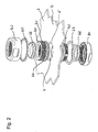
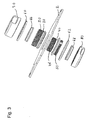
- Figures 2 and 3 show the holder 10 in exploded views in different perspective.
- the holder 10 is intended to fasten a cylindrical element, for example a sensor, in an opening 4 of a plate 2.
- a cylindrical element for example a sensor
- In the plate 2 is generally a mounting surface which is plate-shaped at least in the region of the opening 4.
- the plate 2 has a first side 6 and a second side 8.
- a longitudinal axis 12 of the holder 10 is arranged transversely to a plane of the plate.
- the plate 2 may be located in a hygienically demanding area, for example in a food processing operation.
- the installation of the sensor must meet certain hygiene requirements, including in particular a gap-free arrangement and a good cleanability. This basically applies to both sides 6, 8 of the plate 2.
- the plate 2 may represent a boundary between a hygienic area and a non-hygienic area. In this case, the assembly must be hygienic only on one of the sides 6, 8 of the plate 2.
- the holder 10 comprises two bushing parts, namely a first bushing part 20 and a second bushing part 40.
- first bushing part 20 is located on the first side 6 of the plate 2 and the second bushing part 40 is on the second side 8 of the plate 2.
- the first female part 20 has a first connecting portion for connection to the second female part 40, which is guided in the mounted state through the opening 4 of the plate 2.
- the second female part 40 has a second connecting portion for connection to the first female part 20, which projects into the aperture 4.
- Both socket parts 20, 40 are thus arranged in the assembled state with a portion in the opening 4 of the plate 2, wherein one of the socket parts 20, 40 is guided through the opening 4 on the opposite side of the plate 2 and the other socket part only in the opening 4 protrudes. In principle, however, it is sufficient if only one of the two bushing parts 20, 40 protrudes into the opening 4 or is passed through it.
- the bushing parts 20, 40 can be screwed together.
- a first thread 28 is provided on the first socket part 20 and a second thread 48 on the second socket part 40.
- One of the threads 28, 48 is as external thread and the other is designed as internal thread.
- the first female part 20, whose connecting portion is passed through the opening 4, an external thread and the second female part 40 has an internal thread.
- the two bush parts 20, 40 each have an opening 22, 42 for receiving the cylindrical object, for example the sensor.
- the openings 22, 42 are aligned coaxially with the opening 4 in the plate 2 in the mounted state of the holder 10.
- At least one of the bushing parts 20, 40 which may also be referred to as inner bushing part, has a substantially cylindrical inner circumferential surface.
- both socket parts 20, 40 have at least one section with a cylindrical inner lateral surface, preferably with the same diameters.
- a first cap sleeve 70 is screwed, which has an opening through which the cylindrical object can be passed.
- the first socket part 20 has an external thread 30 and the cap sleeve 70 has an internal thread 72.
- a second cap sleeve 80 is screwed in a corresponding manner.
- the second bushing part 40 has an external thread 50 and the cap sleeve 80 has an internal thread 82.
- the holder 10 is sealed relative to the plate 2.
- two seals 60, 62 are provided, which are arranged in the mounted state on opposite sides of the plate 2.
- a first seal 60 is disposed between the first cap sleeve 70 and the plate 2 and thus seals a gap between the first cap sleeve 70 and the plate 2.
- a second seal 62 is disposed between the second cap sleeve 80 and the plate 2, thus sealing a gap between the second cap sleeve 80 and the plate 2.
- stop surfaces are provided on the socket parts 20, 40, through which the respective gap to be sealed receives a defined size, so that in the assembled state a defined Deformation is caused.
- the holder 10 can also be used in hygienically demanding environments, such as in the food industry.
- the first socket part 20 has a first stop face 24 with which the first socket part 20 can be supported on the plate 2. Furthermore, the first socket part 20 has a second stop face 26, on which the first cap sleeve 70 can be supported in such a way that a gap of a defined size is formed between the plate 2 and the first cap sleeve 70 in the mounted state.
- the first seal 60 is disposed in the gap between the plate 2 and the first cap sleeve 70 and is compressed in the assembled state by a defined amount. This results in a defined deformation of the seal 60.
- the seal 60 is adapted so that a gap-free transition from the plate 2 to the first cap sleeve 70 is generated by the defined deformation.
- the first bushing part 20 has a collar-like, annular projection 21 on which the abutment surface 24 is formed on a first side and the abutment surface 26 on a second side.
- the second bushing part 40 accordingly has a third stop surface 44 with which it can be supported on the opposite side 6 of the plate 2. Furthermore, the second socket part 40 has a fourth stop surface 46, on which the second cap sleeve 80 can be supported in such a way that a gap of a defined size is formed between the plate 2 and the second cap sleeve 80 in the mounted state.
- the second seal 62 is disposed in the gap between the plate 2 and the second cap sleeve 80 and is compressed in the assembled state by a defined amount. This results in a defined deformation of the seal 62.
- the seal 62 is adapted so that a gap-free transition from the plate 2 to the second cap sleeve 80 is generated by the defined deformation.
- the second bushing part 40 has a collar-like, annular projection 41 on which the abutment surface 44 is formed on a first side and the abutment surface 46 on a second side.
- the holder 10 is completely sealed against the plate 2 and there are no gaps or cracks, where deposits can settle.
- a third seal 66 is disposed in an axial opening of the first cap sleeve 70 and provides a gap-free transition from the first cap sleeve 70 to the cylindrical object.
- the third seal 66 has a collar section 67, which in the mounted state is supported on a collar-like support region 74 of the first coupling sleeve 70.
- the collar portion 67 is received between the collar-like support portion 74 and the first female part 20.
- the support region 74 of the first cap sleeve 70 has a conical inner surface 76 and the third seal 66 has a conical outer surface 78.
- the conical inner circumferential surface 76 of the first cap sleeve 70 is more inclined relative to the longitudinal axis 12 of the holder than the conical outer lateral surface 78 of the third seal 66. Due to the different cone angle of the cap sleeve 70 and the third seal 66 results in a pressure peak on the outwardly directed sealing edge , which ensures a hygienic and gap-free sealing.
- an edge is formed on the cap sleeve 70 at an outer transition region between the first cap sleeve 70 and the seal 66, which acts as a cutting edge, so that material of the first cap sleeve 70 works into the seal 66.
- the seal 66 is also pressed over the conical outer circumferential surface 78 to the cylindrical object and thus leads to a hygienic, gap-free transition from the seal 66 to the cylindrical object.
- the mutually obliquely directed conical surfaces on the cap sleeve 70 and the third seal 66 are moved axially to each other during assembly, while the cap sleeve 70 is moved in the direction of the stop surface 26 screwing.
- a fourth seal 68 with a corresponding collar portion 69 and a conical outer circumferential surface is arranged at the opposite end of the holder 10 between the second sleeve part 40 and the second cap sleeve 80.
- one of the bush parts 20, 40 preferably the second bushing part 40, an engagement contour, which is adapted to a corresponding contour of the opening 4.
- the breakthrough is preferably not circular and may for example have a flattening 5. Accordingly, the engagement contour also includes a corresponding flattening.
- FIG Fig. 4 Another embodiment of a holder 10, which does not belong to the invention, is shown in FIG Fig. 4 shown.
- the first socket part 20 on a collar 34 which is integrally formed on an outer circumferential surface of the female part 20 and has an annular shape.
- the collar 34 is located on an outer circumferential surface of the socket part 20 between the first stop surface 24 and the second stop surface 26 and has a profiled outer contour 36th
- the first seal 60 is disposed between the plate 2 and the collar 34 unlike the first embodiment.
- the first stop surface 24 is supported on the plate 2 in the mounted state.
- a gap of a defined size between the plate 2 and the collar 34 is formed in the assembled state, so that the first seal 60 is compressed in the mounted state by a defined amount and deformed defined.
- the seal 60 is adapted so that the defined deformation creates a gap-free transition from the plate 2 to the collar 34.
- a fifth seal 64 is disposed between the collar 34 and the first cap sleeve 70.
- the cap sleeve 70 is supported on the second stop surface 26, so that a gap of a defined Size between the first cap sleeve 70 and the collar 34 is formed.
- the fifth seal 64 is compressed in the assembled state by a defined amount and defined deformed.
- the holder 10 allows in a hygienic environment an attachment of a cylindrical object, in particular a sensor, in a breakthrough 4 a plate 2. All seals are suitable for use in a hygienic environment and seal substantially gap-free. Through the use of suitable materials with smooth surfaces and a favorable shape, the holder is easy to clean and therefore overall well suited for use in the hygienic field.
Landscapes
- Engineering & Computer Science (AREA)
- General Engineering & Computer Science (AREA)
- Mechanical Engineering (AREA)
- Apparatus For Disinfection Or Sterilisation (AREA)
- Food-Manufacturing Devices (AREA)
- Closures For Containers (AREA)
Description
- Die Erfindung betrifft eine Halterung für ein zylindrisches Objekt, insbesondere ein Rohr oder einen Sensor, in einem Durchbruch einer Platte in einer hygienisch anspruchsvollen Umgebung nach dem Oberbegriff des Anspruchs 1. Eine solche Halterung ist aus der
FR 1 562 838 A - In hygienisch anspruchsvollen Umgebungen, beispielsweise in der Lebensmittelindustrie oder im medizinischen Bereich, müssen Anlagen und Geräte bestimmte Anforderungen hinsichtlich Gestaltung und Reinigbarkeit erfüllen, die zumeist in entsprechenden Normen und Richtlinien niedergelegt sind. Solche Normen und Richtlinien sind beispielsweise von der Food and Drug Administration (FDA) oder der European Hygienic Engineering and Design Group (EHEDG) erlassen worden.
- Ein wichtiges Kriterium bei der Gestaltung von Anlagen und Geräten für hygienische Bereiche, welche auch als Nass- oder Spritzbereiche bezeichnet werden, ist die Vermeidung von Spalten, Ritzen oder sonstigen schwer zugänglichen Orten, an denen sich Schmutz oder Reinigungsmittelreste anlagern können.
- Dementsprechend sind beispielsweise Sensoren entwickelt worden, die diese Anforderungen erfüllen. Solche Sensoren haben meist eine zylindrische äußere Form ohne Spalten oder Ritzen, in denen sich Schmutzstoffe oder Reinigungsmittel ablagern können.
- Häufig ist es erforderlich, solche Sensoren an einer Montageoberfläche, insbesondere einer Montageplatte, zu befestigen. Entsprechende Halterungen oder Befestigungselemente müssen daher, insbesondere im Zusammenspiel mit den Sensoren, ebenfalls die genannten Anforderungen erfüllen. Bei der Montageplatte kann es sich grundsätzlich um eine zwischen einer hygienischen Umgebung und einer nichthygienischen Umgebung angeordnete Platte oder auch um einen frei im Raum stehenden Halter handeln, der von beiden Montageseiten her hygienischen Anforderungen genügen muss.
- Um eine solche Halterung in einem hygienisch anspruchsvollen Umfeld, beispielsweise in der Lebensmittelindustrie oder im medizinischen Bereich, einsetzen zu können, muss die Halterung spaltfrei ausgeführt und gut zu reinigen sein, damit sich keine Schmutzstoffe in Ritzen oder Spalten festsetzen können.
- Der Erfindung liegt die Aufgabe zugrunde, eine Halterung für ein zylindrisches Objekt in einem Durchbruch einer Platte bereitzustellen, die spaltfrei ausgeführt und leicht zu reinigen ist.
- Die Aufgabe wird erfindungsgemäß durch eine Halterung mit den Merkmalen des Anspruchs 1 gelöst. Vorteilhafte Ausgestaltungen sind in den abhängigen Ansprüchen, der nachfolgenden Beschreibung sowie den Figuren beschrieben beziehungsweise dargestellt.
- Die oben genannte Halterung ist erfindungsgemäß dadurch weitergebildet, dass an dem ersten Buchsenteil eine Anschlagfläche gebildet ist, durch welche das erste Buchsenteil so an der Platte abstützbar ist, dass die Dichtung in einem montierten Zustand in dem Aufnahmebereich um ein definiertes Maß zusammenpressbar ist, wobei eine definierte Verformung der Dichtung zum Herstellen eines spaltfreien Übergangs erzeugbar ist.
- Der Zweck der Dichtung besteht im Wesentlichen darin, die Buchsenteile spaltfrei mit der Platte zu verbinden, um Spalten oder Ritzen zwischen den Buchsenteilen und der Platte, an denen sich Ablagerungen ansammeln können, zu vermeiden. Des Weiteren dient die Dichtung einer im Wesentlichen spaltfreien Aufnahme des zylindrischen Objekts, so dass sich auch zwischen den Buchsenteilen und dem zylindrischen Objekt keine Ablagerungen ansammeln können.
- Ein Grundgedanke der Erfindung besteht darin, die Halterung so zu gestalten, dass bei einem Befestigen der Halterung an der Platte eine definierte Verformung der Dichtung erzeugt wird.
- Hierzu ist erfindungsgemäß vorgesehen, an dem ersten Buchsenteil eine Anschlagfläche bereitzustellen, mit welcher das Buchsenteil an der Platte abstützbar ist. Hierdurch wird erreicht, dass die Dichtung derart zwischen der Platte und einem Teil der Halterung positioniert werden kann, dass bei einem Abstützen des Buchsenteils an der Platte die Dichtung um ein definiertes Maß zwischen der Platte und einem Teil der Halterung zusammengepresst wird. Durch das Zusammenpressen erfolgt eine definierte Verformung der Dichtung. Die Dichtung ist so ausgeführt, dass durch die definierte Verformung ein im Wesentlichen spaltfreier Übergang von der Halterung zu der Platte erzeugt wird.
- Durch die Anschlagfläche wird erreicht, dass ein Aufnahmebereich einer definierten Größe bereitgestellt wird, so dass die Dichtung beim Befestigen der Halterung an der Platte nicht beliebig zusammengedrückt werden kann, sondern eine definierte, durch die Anschlagfläche begrenzte Verformung erfährt. Die Verformung ist somit konstruktiv vorgegeben und nicht abhängig von der Handhabung oder Bedienung der Halterung durch einen Anwender. Vorzugsweise stützt sich die Anschlagfläche direkt an der Platte ab, das heißt es besteht ein direkter Kontakt zwischen der Anschlagfläche und der Platte. Grundsätzlich ist es aber auch möglich, dass die Abstützung über ein Zwischenelement erfolgt.
- Die Anschlagfläche beziehungsweise die Größe des Aufnahmebereichs und die Dichtung sind dabei so aufeinander abgestimmt, dass die Dichtung beim Befestigen des Buchsenteils oder der Halterung an der Platte auf ein durch die Anschlagfläche begrenztes definiertes Maß gepresst oder gedrückt wird, wodurch die gewünschte Verformung erreicht wird.
- Unter einem spaltfreien Übergang ist vorliegend insbesondere ein Übergang zu verstehen, der für die Zwecke der Hygiene geeignet ist.
- Die Dichtung ist vorzugsweise ringförmig gestaltet und weist eine an den Aufnahmbereich angepasste Querschnittsform auf. Eine äußere Mantelfläche der Dichtung kann im unmontierten Zustand im Wesentlichen zylinderförmig sein.
- Unter einer definierten Verformung der Dichtung ist insbesondere ein Zusammendrücken oder Zusammenpressen in einer axialen Richtung, das heißt in einer Richtung parallel zu einer Rotationsachse der Dichtung, zu verstehen. Dies bewirkt eine Reduzierung der axialen Ausdehnung der Dichtung, das heißt, es wird eine axiale Dicke der Dichtung verringert. Durch diese Dickenreduzierung erfolgt eine Durchmesservergrößerung. Dabei entsteht an der Mantelfläche eine Wölbung, welche einen Radius aufweist, der so groß ist, dass ein leicht zu reinigender und im Wesentlichen spaltfreier Übergang zwischen der Dichtung und der Platte sowie zwischen der Dichtung und einem angrenzenden Teil der Halterung erzielt wird.
- Die beiden Buchsenteile können grundsätzlich auf beliebige Weise miteinander verbunden werden. Eine besonders vorteilhafte Verbindungsart besteht jedoch darin, dass das erste Buchsenteil und das zweite Buchsenteil jeweils ein Gewinde zum miteinander Verschrauben aufweisen. Das Gewinde ermöglicht die Verwendung der Halterung mit Platten unterschiedlicher Stärke beziehungsweise Dicke. Dabei werden die Buchsenteile vorzugsweise so weit ineinander verschraubt, bis zumindest eine Anschlagfläche an der Platte anliegt und so mindestens ein Buchsenteil an der Platte abgestützt wird.
- Sofern beide Seiten der Platte zu einem hygienisch anspruchsvollen Bereich gehören ist es bevorzugt, dass beide Buchsenteile eine Anschlagfläche aufweisen, durch welche sie an der Platte abstützbar sind. Weiterhin ist es bevorzugt, dass zwei Dichtungen vorgesehen sind, die im montierten Zustand um ein definiertes Maß zusammenpressbar sind, wobei jeweils eine definierte Verformung der Dichtung zum Herstellen eines spaltfreien Übergangs erzeugbar ist.
- Vorzugsweise ist die Anschlagfläche in einer Ebene angeordnet, die quer zu einer Längsachse der Öffnungen der Buchsenteile verläuft.
- In einer bevorzugten Ausführungsform ist eine weitere Dichtung zum Anordnen zwischen dem zweiten Buchsenteil und der Platte vorgesehen. Die weitere Dichtung dichtet damit einen Übergang oder Spalt zwischen dem zweiten Buchsenteil und der Platte ab. Dabei liegt die Dichtung zwischen einer Anlagefläche an dem zweiten Buchsenteil und einer Oberfläche der Platte. Ein Abstand zwischen der Anlagefläche und der Oberfläche der Platte ist dabei so an die Dichtung angepasst, dass die gewünschte definierte Verformung erreicht wird, wenn das zweite Buchsenteil die Platte an der Anschlagfläche kontaktiert.
- Erfindungsgemäß ist vorgesehen, dass mindestens eine erste Überwurfhülse vorhanden ist, welche mit dem ersten Buchsenteil verbindbar, insbesondere verschraubbar ist. Die Überwurfhülse kann insbesondere dazu dienen, einen direkten Kontakt des Buchsenteils mit der Umgebung zu vermeiden. Hierdurch ist es möglich, das Buchsenteil aus einem Werkstoff herzustellen, welcher für einen Einsatz in einer hygienischen Umgebung nicht geeignet ist. Die Überwurfhülse besteht vorzugsweise aus einem harten, für eine hygienische Umgebung geeigneten Werkstoff, wie beispielsweise ein entsprechender Kunststoff oder Edelstahl.
- Erfindungsgemäß ist die Dichtung zum Anordnen zwischen der ersten Uberwurfhülse und der Platte vorgesehen. Hierzu weist das erste Buchsenteil, mit welchem die erste Überwurfhülse zu verbinden ist, eine erste Anschlagfläche zum Abstützen an der Platte und eine zweite Anschlagfläche auf, an welcher die Überwurfhülse abstützbar ist. Die beiden Anschlagflächen, die Überwurfhülse und die Dichtung sind so aufeinander abgestimmt, dass in einem montierten Zustand ein definierter Spalt oder Aufnahmebereich zwischen der Platte und der Überwurfhülse gebildet wird, in welchem die Dichtung um ein definiertes Maß zusammenpressbar ist. Hierdurch wird die gewünschte Verformung zur Ausbildung einer spaltfreien Abdichtung beziehungsweise eines spaltfreien Übergangs erzeugt.
- Es ist bevorzugt, dass die Überwurfhülse eine Öffnung zum Hindurchführen des zylindrischen Objekts aufweist und dass zum Abdichten eines Spalts zwischen dem zylindrischen Objekts und der Überwurfhülse mindestens eine weitere Dichtung angeordnet ist. Die Öffnung in der Überwurfhülse ist vorzugsweise kreisförmig gestaltet und an einer axialen Stirnseite der Halterung angeordnet. Die weitere Dichtung weist vorzugsweise einen radial nach außen vorstehenden Bundabschnitt auf, der zwischen einer axialen Stirnfläche der Überwurfhülse und einer axialen Stirnfläche des Buchsenteils im montierten Zustand angeordnet ist.
- Eine einfache Verschraubung der Buchsenteile miteinander lässt sich dadurch erreichen, dass das zweite Buchsenteil einen radial nach außen vorstehenden Bund aufweist, dass eine zweite Dichtung zum Anordnen zwischen dem Bund und der Platte vorgesehen ist und dass eine weitere Dichtung zwischen dem Bund und einer zweiten Überwurfhülse angeordnet ist. Der Bund bietet einen Angriffspunkt für das zweite Buchsenteil, mit welchem das zweite Buchsenteil gegenüber dem ersten Buchsenteil zum Herstellen oder Lösen der Schraubverbindung gedreht werden kann. Grundsätzlich kann der Bund einstückig mit dem zweiten Buchsenteil ausgebildet sein. Es ist aber auch möglicht, dass der Bund als separates, mit dem Buchsenteil fest verbundenes Teil hergestellt ist. Der Bund kann ein anderes Material aufweisen als das Buchsenteil.
- Eine besonders einfache Verschraubung lässt sich erzielen, wenn der Bund eine profilierte Außenkontur aufweist. Die Außenkontur kann insbesondere so ausgestaltet sein, dass sie an einen Schraubenschlüssel angepasst ist. Hierdurch lässt sich das zweite Buchsenteil mit einem Schraubenschlüssel verdrehen.
- Eine vorteilhafte Ausgestaltung besteht darin, dass der Bund zumindest bereichsweise radial nach außen über die zweite und die zwischen dem Bund und der Überwurfhülse angeordnete weitere Dichtung hervorsteht. Hierdurch kann der Bund einfach, beispielsweise mittels eines Schraubenschlüssels, kontaktiert werden, ohne dass die Dichtungen den Zugang zu dem Bund versperren. Weiterhin ist es bevorzugt, dass der Bund über die Überwurfhülse zumindest bereichsweise radial hervorsteht. Der Bund hat also vorzugsweise zumindest bereichsweise einen Außendurchmesser, welcher größer ist als ein maximaler Außendurchmesser der beiden Dichtungen und der Überwurfhülse.
- Gemäß einer weiteren bevorzugten Ausgestaltung ist vorgesehen, dass das erste Buchsenteil und/oder das zweite Buchsenteil eine Fixierungskontur zur drehfesten Fixierung an dem Durchbruch der Platte aufweist. Hierdurch ist es möglich, dass entsprechende Buchsenteil drehfest in der Platte anzuordnen, so dass das weitere Buchsenteil mit dem ersten Buchsenteil verschraubt werden kann, ohne dass sich das erste Buchsenteil mitdreht. Gemäß dieser Ausführungsform ist vorgesehen, dass die Platte eine zumindest nicht kreisrunde Öffnung aufweist.
- Die Halterungsteile sind vorzugsweise aus Lebensmittel zugelassenem V4A-Stahl ausgeführt. Sie können als Drehteil, Feingussteil oder im Spritzgussverfahren, insbesondere durch sogenanntes Metallpulver Spritzgießen (MIM-Metal injection molding) hergestellt sein. Zur Erzeugung einer glatten Oberfläche können die Teile gleitgeschliffen oder elektropoliert sein.
- Alle Dichtungselemente beziehungsweise Dichtungen sind vorzugsweise aus einem Werkstoff hergestellt, der für den Lebensmittelbereich zugelassen ist. Besonders bevorzugte Werkstoffe sind Fluorelastomere (FKM) oder Silikon-Kautschuk (VMQ).
- Weitere Vorteile und Merkmale der erfindungsgemäßen Halterung werden nachstehend mit Bezug auf die beigefügten schematischen Zeichnungen in weiteren Details beschrieben. Hierin zeigt:
- Fig. 1
- eine Querschnittsansicht einer Ausführungsform einer erfindungsgemäßen Halterung im montierten Zustand;
- Fig. 2
- eine Explosionsdarstellung der Halterung aus
Fig. 1 ; - Fig. 3
- eine weitere Explosionsdarstellung der Halterung aus
Fig. 1 und - Fig. 4
- Querschnittsansicht einer Ausführungsform einer nicht erfindungsgemäßen Halterung im montierten Zustand.
- Eine Ausführungsform einer erfindungsgemäßen Halterung wird nachstehend mit Bezug auf die
Figuren 1 bis 3 beschrieben.Fig. 1 zeigt die Halterung 10 in einem montierten Zustand.Figuren 2 und3 zeigen die Halterung 10 in Explosionsdarstellungen in unterschiedlicher Perspektive. - Die Halterung 10 ist dazu vorgesehen, ein zylindrisches Element, beispielsweise einen Sensor, in einem Durchbruch 4 einer Platte 2 zu befestigen. Bei der Platte 2 handelt es sich allgemein um eine Montagefläche, die zumindest im Bereich des Durchbruchs 4 plattenförmig ausgebildet ist. Die Platte 2 weist eine erste Seite 6 und eine zweite Seite 8 auf. Eine Längsachse 12 der Halterung 10 ist quer zu einer Plattenebene angeordnet.
- Die Platte 2 kann sich in einem hygienisch anspruchsvollen Bereich, beispielsweise in einem Lebensmittel verarbeitenden Betrieb, befinden. Die Montage des Sensors muss entsprechend gewisse Hygieneanforderungen erfüllen, wozu insbesondere eine spaltfreie Anordnung und eine gute Reinigbarkeit gehören. Dies betrifft grundsätzlich beide Seiten 6, 8 der Platte 2. In bestimmten Situationen kann allerdings die Platte 2 eine Grenze zwischen einem hygienischen Bereich und einem nicht hygienischen Bereich darstellen. In diesem Fall muss die Montage lediglich auf einer der Seiten 6, 8 der Platte 2 hygienisch sein.
- Die Halterung 10 umfasst zwei Buchsenteile, nämlich ein erstes Buchsenteil 20 und ein zweites Buchsenteil 40. Im montierten Zustand befindet sich das erste Buchsenteil 20 auf der ersten Seite 6 der Platte 2 und das zweite Buchsenteil 40 auf der zweiten Seite 8 der Platte 2.
- Das erste Buchsenteil 20 weist einen ersten Verbindungsabschnitt zum Verbinden mit dem zweiten Buchsenteil 40 auf, welcher im montierten Zustand durch den Durchbruch 4 der Platte 2 hindurchgeführt ist. Das zweite Buchsenteil 40 weist einen zweiten Verbindungsabschnitt zum Verbinden mit dem ersten Buchsenteil 20 auf, welcher in den Durchbruch 4 hineinragt.
- Beide Buchsenteile 20, 40 sind somit im montierten Zustand mit einem Abschnitt in dem Durchbruch 4 der Platte 2 angeordnet, wobei eines der Buchsenteile 20, 40 durch den Durchbruch 4 auf die gegenüberliegende Seite der Platte 2 geführt ist und das andere Buchsenteil lediglich in den Durchbruch 4 hineinragt. Grundsätzlich ist es jedoch ausreichend, wenn nur eines der beiden Buchsenteile 20, 40 in den Durchbruch 4 hineinragt oder durch diesen hindurchgeführt ist.
- Die Buchsenteile 20, 40 können miteinander verschraubt werden. Hierzu ist an dem ersten Buchsenteil 20 ein erstes Gewinde 28 und an dem zweiten Buchsenteil 40 ein zweites Gewinde 48 vorhanden. Eines der Gewinde 28, 48 ist als Außengewinde und das andere ist als Innengewinde ausgeführt. In der dargestellten Ausführungsform weist das erste Buchsenteil 20, dessen Verbindungsabschnitt durch den Durchbruch 4 hindurchgeführt ist, ein Außengewinde und das zweite Buchsenteil 40 ein Innengewinde auf.
- Die beiden Buchsenteile 20, 40 weisen jeweils eine Öffnung 22, 42 zur Aufnahme des zylindrischen Objekts, zum Beispiel des Sensors, auf. Die Öffnungen 22, 42 sind im montierten Zustand der Halterung 10 koaxial zu dem Durchbruch 4 in der Platte 2 ausgerichtet. Zumindest eines der Buchsenteile 20, 40, welches auch als inneres Buchsenteil bezeichnet werden kann, weist eine im Wesentlichen zylinderförmige innere Mantelfläche auf. Für eine stabile Halterung des Sensors haben jedoch beide Buchsenteile 20, 40 mindestens einen Abschnitt mit einer zylinderförmigen inneren Mantelfläche, vorzugsweise mit gleichen Durchmessern.
- Auf das erste Buchsenteil 20 ist eine erste Überwurfhülse 70 aufgeschraubt, die eine Öffnung aufweist, durch die das zylindrische Objekt hindurchgeführt werden kann. Zum Aufschrauben der Überwurfhülse 70 weist das erste Buchsenteil 20 ein Außengewinde 30 und die Überwurfhülse 70 ein Innengewinde 72 auf.
- Auf das zweite Buchsenteil 40 ist eine zweite Überwurfhülse 80 in entsprechender Weise aufgeschraubt. Das zweite Buchsenteil 40 weist hierzu ein Außengewinde 50 und die Überwurfhülse 80 ein Innengewinde 82 auf.
- Damit sich zwischen der Platte 2 und der Halterung 10 keine Schmutzstoffe oder sonstige Ablagerungen festsetzen können, ist die Halterung 10 gegenüber der Platte 2 abgedichtet. Hierzu sind zwei Dichtungen 60, 62 vorgesehen, die im montierten Zustand auf gegenüberliegenden Seiten der Platte 2 angeordnet sind. Eine erste Dichtung 60 ist zwischen der ersten Überwurfhülse 70 und der Platte 2 angeordnet und dichtet so einen Spalt zwischen der ersten Überwurfhülse 70 und der Platte 2 ab. Eine zweite Dichtung 62 ist zwischen der zweiten Überwurfhülse 80 und der Platte 2 angeordnet und dichtet so einen Spalt zwischen der zweiten Überwurfhülse 80 und der Platte 2 ab.
- Um an den genannten Stellen jeweils einen im Wesentlichen spaltfreien Übergang beziehungsweise eine spaltfreie Abdichtung zu erzielen, sind an den Buchsenteilen 20, 40 Anschlagflächen vorgesehen, durch welche der jeweils abzudichtende Spalt eine definierte Größe erhält, so dass bei der einzusetzenden Dichtung im montierten Zustand eine definierte Verformung hervorgerufen wird. Hierdurch kann die Halterung 10 auch in hygienisch anspruchsvollen Umgebungen, wie beispielsweise im Lebensmittelbereich, eingesetzt werden.
- Bei der in den
Figuren 1 bis 3 dargestellten Ausführungsform weist das erste Buchsenteil 20 eine erste Anschlagfläche 24 auf, mit der das erste Buchsenteil 20 an der Platte 2 abgestützt werden kann. Weiterhin weist das erste Buchsenteil 20 eine zweite Anschlagfläche 26 auf, an welcher die erste Überwurfhülse 70 derart abgestützt werden kann, dass im montierten Zustand ein Spalt einer definierten Größe zwischen der Platte 2 und der ersten Überwurfhülse 70 gebildet wird. Die erste Dichtung 60 ist in dem Spalt zwischen der Platte 2 und der ersten Überwurfhülse 70 angeordnet und wird im montierten Zustand um ein definiertes Maß zusammengepresst. Hierdurch entsteht eine definierte Verformung der Dichtung 60. Die Dichtung 60 ist so angepasst, dass durch die definierte Verformung ein spaltfreier Übergang von der Platte 2 zu der ersten Überwurfhülse 70 erzeugt wird. - Zur Bereitstellung der Anschlagflächen 24, 26 weist das erste Buchsenteil 20 einen bundartigen, ringförmigen Vorsprung 21 auf, an dem auf einer ersten Seite die Anschlagfläche 24 und auf einer zweiten Seite die Anschlagfläche 26 gebildet ist.
- Das zweite Buchsenteil 40 weist entsprechend eine dritte Anschlagfläche 44 auf, mit welcher es an der gegenüberliegenden Seite 6 der Platte 2 abstützbar ist. Weiterhin weist das zweite Buchsenteil 40 eine vierte Anschlagfläche 46 auf, an welcher die zweite Überwurfhülse 80 derart abgestützt werden kann, dass im montierten Zustand ein Spalt einer definierten Größe zwischen der Platte 2 und der zweiten Überwurfhülse 80 gebildet wird. Die zweite Dichtung 62 ist in dem Spalt zwischen der Platte 2 und der zweiten Überwurfhülse 80 angeordnet und wird im montierten Zustand um ein definiertes Maß zusammengepresst. Hierdurch entsteht eine definierte Verformung der Dichtung 62. Die Dichtung 62 ist so angepasst, dass durch die definierte Verformung ein spaltfreier Übergang von der Platte 2 zu der zweiten Überwurfhülse 80 erzeugt wird.
- Zur Bereitstellung der Anschlagflächen 44, 46 weist das zweite Buchsenteil 40 einen bundartigen, ringförmigen Vorsprung 41 auf, an dem auf einer ersten Seite die Anschlagfläche 44 und auf einer zweiten Seite die Anschlagfläche 46 gebildet ist.
- Durch die Dichtungen 60, 62 ist die Halterung 10 vollständig gegenüber der Platte 2 abgedichtet und es entstehen keine Spalten oder Ritzen, an denen sich Ablagerungen festsetzen können.
- Zur Abdichtung eines Spalts zwischen dem zylindrischen Objekt und den Überwurfhülsen 70, 80 sind weitere Dichtungen 66, 68 vorgesehen. Eine dritte Dichtung 66 ist in einer axialen Öffnung der ersten Überwurfhülse 70 angeordnet und stellt einen spaltfreien Übergang von der ersten Überwurfhülse 70 zu dem zylindrischen Objekt bereit.
- Zur axialen Fixierung der dritten Dichtung 66 weist die dritte Dichtung 66 einen Bundabschnitt 67 auf, welcher sich im montierten Zustand an einem bundartigen Abstützbereich 74 der ersten Überwurfhülse 70 abstützt. Der Bundabschnitt 67 ist zwischen dem bundartigen Abstützbereich 74 und dem ersten Buchsenteil 20 aufgenommen.
- Um zwischen der ersten Überwurfhülse 70 und der dritten Dichtung 66 einen spaltfreien Übergang bereitzustellen, weist der Abstützbereich 74 der ersten Überwurfhülse 70 eine kegelige Innenmantelfläche 76 und die dritte Dichtung 66 eine kegelige Außenmantelfläche 78 auf. Die kegelige Innenmantelfläche 76 der ersten Überwurfhülse 70 ist gegenüber der Längsachse 12 der Halterung stärker geneigt als die kegelige Außenmantelfläche 78 der dritten Dichtung 66. Durch die unterschiedlichen Kegelwinkel an der Überwurfhülse 70 und der dritten Dichtung 66 ergibt sich an der nach außen gerichteten Dichtkante eine Druckspitze, die eine hygienische und spaltfreie Abdichtung sicherstellt. Dabei ist an der Überwurfhülse 70 an einem äußeren Übergangsbereich zwischen der ersten Überwurfhülse 70 und der Dichtung 66 eine Kante gebildet, die als eine Schneide wirkt, so dass sich Material der ersten Überwurfhülse 70 in die Dichtung 66 hineinarbeitet.
- Durch ein Anziehen beziehungsweise Aufschrauben der Überwurfhülse 70 auf das Buchsenteil 20 wird die Dichtung 66 zudem über die kegelige Außenmantelfläche 78 zum zylindrischen Objekt hin gedrückt und führt so zu einem hygienischen, spaltfreien Übergang von der Dichtung 66 zu dem zylindrischen Objekt.
- Die zueinander schräg gerichteten Kegelflächen an der Überwurfhülse 70 und der dritten Dichtung 66 werden während der Montage axial zueinander bewegt, während die Überwurfhülse 70 in Richtung der Anschlagfläche 26 schraubend bewegt wird.
- Durch die Abstützung der ersten Überwurfhülse 70 an der zweiten Anschlagfläche 26 des ersten Buchsenteils 20 ist zwischen der Überwurfhülse 70 und dem Buchsenteil 20 definierter Spalt mit einer definierten Größe gebildet.
- In entsprechender Weise ist an dem gegenüberliegenden Ende der Halterung 10 zwischen dem zweiten Buchsenteil 40 und der zweiten Überwurfhülse 80 eine vierte Dichtung 68 mit einem entsprechenden Bundabschnitt 69 und einer kegeligen Außenmantelfläche angeordnet.
- Zur drehfesten Aufnahme in dem Durchbruch 4 der Platte 2 weist eines der Buchsenteile 20, 40, vorzugsweise das zweite Buchsenteil 40, eine Eingriffskontur auf, die an eine entsprechende Kontur des Durchbruchs 4 angepasst ist. Der Durchbruch ist vorzugsweise nicht kreisrund ausgeführt und kann beispielsweise eine Abflachung 5 aufweisen. Dementsprechend umfasst die Eingriffskontur ebenfalls eine entsprechende Abflachung.
- Eine weitere Ausführungsform einer Halterung 10, die nicht zur Erfindung gehört, ist in
Fig. 4 dargestellt. - Im Unterschied zu der erfindungsgemäßen Ausführungsform weist das erste Buchsenteil 20 einen Bund 34 auf, der an einer äußeren Mantelfläche des Buchsenteils 20 angeformt ist und eine ringförmige Gestalt hat. Der Bund 34 befindet sich an einer äußeren Mantelfläche des Buchsenteils 20 zwischen der ersten Anschlagfläche 24 und der zweiten Anschlagfläche 26 und hat eine profilierte Außenkontur 36.
- Die erste Dichtung 60 ist im Unterschied zu der ersten Ausführungsform zwischen der Platte 2 und dem Bund 34 angeordnet. Die erste Anschlagfläche 24 stützt sich im montierten Zustand an der Platte 2 ab. Hierdurch wird im montierten Zustand ein Spalt einer definierten Größe zwischen der Platte 2 und dem Bund 34 gebildet, so dass die erste Dichtung 60 im montierten Zustand um ein definiertes Maß zusammengepresst und definiert verformt wird. Die Dichtung 60 ist so angepasst, dass durch die definierte Verformung ein spaltfreier Übergang von der Platte 2 zu dem Bund 34 erzeugt wird.
- Zur Abdichtung der ersten Überwurfhülse 70 gegenüber dem Bund 34 ist zwischen dem Bund 34 und der ersten Überwurfhülse 70 eine fünfte Dichtung 64 angeordnet. Um auch hier einen spaltfreien Übergang zu gewährleisten, stützt sich die Überwurfhülse 70 an der zweiten Anschlagfläche 26 ab, so dass ein Spalt einer definierten Größe zwischen der ersten Überwurfhülse 70 und dem Bund 34 entsteht. In diesem Spalt definierter Größe wird die fünfte Dichtung 64 im montierten Zustand um ein definiertes Maß zusammengepresst und definiert verformt.
- Die Halterung 10 ermöglicht in einer hygienischen Umgebung eine Befestigung eines zylindrischen Objekts, insbesondere eines Sensors, in einem Durchbruch 4 einer Platte 2. Alle Dichtungen sind für den Einsatz in einer hygienischen Umgebung geeignet und dichten im Wesentlichen spaltfrei ab. Durch den Einsatz geeigneter Materialien mit glatten Oberflächen und eine günstige Formgebung ist die Halterung einfach zu reinigen und daher insgesamt hervorragend für den Einsatz im hygienischen Bereich geeignet.
Claims (9)
- Halterung für ein zylindrisches Objekt, insbesondere ein Rohr oder einen Sensor, in einem Durchbruch (4) einer Platte (2) in einer hygienisch anspruchsvollen Umgebung- mit einem ersten Buchsenteil (20) zum Anordnen auf einer ersten Seite (6) der Platte (2),- mit einem zweiten Buchsenteil (40) zum Anordnen auf einer zweiten Seite (8) der Platte (2) und- mit mindestens einer Dichtung (60, 62) zum Anordnen in einem Aufnahmebereich zwischen der Halterung (10) und der Platte (2),- wobei die Buchsenteile (20, 40), insbesondere im Bereich des Durchbruchs (4), miteinander verbindbar sind und jeweils eine Öffnung (22, 42) zum Aufnehmen des zylindrischen Objekts aufweisen,wobei mindestens eine erste Überwurfhülse (70) vorhanden ist, welche mit dem
ersten Buchsenteil (20) verbindbar, insbesondere verschraubbar, ist, und wobei das erste Buchsenteil (20) eine erste Anschlagfläche (24) aufweist, mit der das erste Buchsenteil (20) an der Platte (2) abstützbar ist,
dadurch gekennzeichnet,
dass das erste Buchsenteil (20) eine zweite Anschlagfläche (26) aufweist, an welcher die erste Überwurfhülse (70) derart abgestützt werden kann, dass im montierten Zustand ein Spalt einer definierten Größe zwischen der Platte (2) und der ersten Überwurfhülse (70) gebildet wird, und
dass eine erste Dichtung (60) in einem montierten Zustand in dem Spalt zwischen der Platte (2) und der ersten Überwurfhülse (70) angeordnet und um ein definiertes Maß zusammenpressbar ist, wobei eine definierte Verformung der ersten Dichtung (60) zum Herstellen eines spaltfreien Übergangs erzeugbar ist. - Halterung nach Anspruch 1,
dadurch gekennzeichnet,
dass mindestens eine zweite Überwurfhülse (80) vorhanden ist, welche mit dem zweiten Buchsenteil (40) verbindbar, insbesondere verschraubbar, ist, dass das zweite Buchsenteil (40) eine dritte Anschlagfläche (44) aufweist, mit der das zweite Buchsenteil (40) an der Platte (2) abstützbar ist,
dass das zweite Buchsenteil (40) eine vierte Anschlagfläche (46) aufweist, an welcher die zweite Überwurfhülse (80) derart abgestützt werden kann, dass im montierten Zustand ein Spalt einer definierten Größe zwischen der Platte (2) und der zweiten Überwurfhülse (80) gebildet wird, und
dass eine zweite Dichtung (62) in einem montierten Zustand in dem Spalt zwischen der Platte (2) und der zweiten Überwurfhülse (80) angeordnet und um ein definiertes Maß zusammenpressbar ist, wobei eine definierte Verformung der zweiten Dichtung (62) zum Herstellen eines spaltfreien Übergangs erzeugbar ist. - Halterung nach Anspruch 1 oder 2,
dadurch gekennzeichnet,
dass das erste Buchsenteil (20) und/oder das zweite Buchsenteil (40) eine Fixierungskontur zur drehfesten Fixierung an dem Durchbruch (4) in der Platte (2) aufweist. - Halterung nach einem der Ansprüche 1 bis 3,
dadurch gekennzeichnet,
dass die Überwurfhülse (70, 80) eine Öffnung zum Hindurchführen des zylindrischen Objekts aufweist und
dass zum Abdichten eines Spalts zwischen dem zylindrischen Objekt und der Überwurfhülse (70, 80) mindestens eine weitere Dichtung (66, 68) angeordnet ist. - Halterung nach einem der Ansprüche 1 bis 4,
dadurch gekennzeichnet,
dass das erste Buchsenteil (20) und das zweite Buchsenteil (40) jeweils ein Gewinde (28, 48) zum miteinander Verschrauben aufweisen. - Halterung nach Anspruch 1,
dadurch gekennzeichnet,
dass das zweite Buchsenteil (40) einen radial nach außen vorstehenden Bund (34) aufweist,
dass eine zweite Dichtung (62) zwischen dem Bund (34) und der Platte (2) angeordnet ist und
dass eine weitere Dichtung (64) zwischen dem Bund (34) und einer zweiten Überwurfhülse (80) angeordnet ist. - Halterung nach Anspruch 6,
dadurch gekennzeichnet,
dass der Bund (34) eine profilierte Außenkontur (36) aufweist. - Halterung nach Anspruch 6 oder 7,
dadurch gekennzeichnet,
dass der Bund (34) zumindest bereichsweise radial nach außen über die zweite und die zwischen dem Bund (34) und der Überwurfhülse (70, 80) angeordnete weitere Dichtung (64) hervorsteht. - Halterung nach Anspruch 1,
dadurch gekennzeichnet,
dass eine zweite Dichtung (62) zwischen dem zweiten Buchsenteil (40) und der Platte (2) angeordnet ist.
Applications Claiming Priority (2)
| Application Number | Priority Date | Filing Date | Title |
|---|---|---|---|
| DE201020005054 DE202010005054U1 (de) | 2010-04-15 | 2010-04-15 | Halterung für ein zylindrisches Objekt in einer Platte |
| PCT/EP2011/000603 WO2011128007A1 (de) | 2010-04-15 | 2011-02-09 | Halterung für ein zylindrisches objekt in einer platte |
Publications (2)
| Publication Number | Publication Date |
|---|---|
| EP2558760A1 EP2558760A1 (de) | 2013-02-20 |
| EP2558760B1 true EP2558760B1 (de) | 2014-04-09 |
Family
ID=44168452
Family Applications (1)
| Application Number | Title | Priority Date | Filing Date |
|---|---|---|---|
| EP11707076.3A Not-in-force EP2558760B1 (de) | 2010-04-15 | 2011-02-09 | Halterung für ein zylindrisches objekt in einer platte |
Country Status (3)
| Country | Link |
|---|---|
| EP (1) | EP2558760B1 (de) |
| DE (1) | DE202010005054U1 (de) |
| WO (1) | WO2011128007A1 (de) |
Families Citing this family (4)
| Publication number | Priority date | Publication date | Assignee | Title |
|---|---|---|---|---|
| DE102012210700A1 (de) * | 2012-06-25 | 2014-01-02 | Weber Maschinenbau Gmbh Breidenbach | Hygieneverbindungseinrichtung |
| USD704543S1 (en) | 2013-01-07 | 2014-05-13 | Weber Maschinenbau Gmbh Breidenbach | Nut and seal |
| US11788625B2 (en) | 2020-05-27 | 2023-10-17 | Hoffman Enclosures, Inc. | Hygienic hole seal |
| US12460725B1 (en) * | 2022-03-11 | 2025-11-04 | New Aerofarms, Inc. | Fluid fitting couplers and coupling system |
Family Cites Families (11)
| Publication number | Priority date | Publication date | Assignee | Title |
|---|---|---|---|---|
| US1461945A (en) * | 1921-02-21 | 1923-07-17 | William C Shanley | Device for connecting suction pipes to tanks and other receptacles |
| US3104120A (en) * | 1958-12-01 | 1963-09-17 | Ahlport Brodie | Coupling for conduits |
| FR1562838A (de) * | 1967-11-22 | 1969-04-11 | ||
| DE8323881U1 (de) * | 1983-08-19 | 1984-10-04 | Hannemann, Karl-August, 2390 Flensburg | Vorrichtung zur herstellung von abgedichteten wanddurchfuehrungen |
| DE4128632C1 (en) * | 1991-08-29 | 1992-09-24 | U.I. Lapp Gmbh & Co Kg, 7000 Stuttgart, De | Feedthrough clamp for electrical cables etc. - has radially sprung snap clamp members separated from pressure collar on other side of wall |
| GB9204663D0 (en) * | 1992-03-04 | 1992-04-15 | Smiths Industries Plc | Screening fitments and assemblies |
| DE29615988U1 (de) * | 1996-09-14 | 1996-11-07 | Fiberdur GmbH, 52457 Aldenhoven | Vorrichtung zum dichten Durchführen einer Rohrleitung durch eine Wand oder Decke |
| US6193284B1 (en) * | 1998-03-25 | 2001-02-27 | Henny Penny Corporation | Connector for securing heat exchanger tube to heating vessel bulkhead |
| US7121589B2 (en) * | 2003-09-24 | 2006-10-17 | Norwesco, Inc. | Tank fitting and method of use |
| US7735876B2 (en) * | 2008-01-03 | 2010-06-15 | Avc Industrial Corp. | Fastening device for cable and wave hose |
| DE202009010452U1 (de) * | 2009-07-22 | 2009-10-01 | Gerich, Adam | Befestigungsvorrichtung für Bauteile, insbesondere für Kabelanschlüsse o.dgl. |
-
2010
- 2010-04-15 DE DE201020005054 patent/DE202010005054U1/de not_active Expired - Lifetime
-
2011
- 2011-02-09 EP EP11707076.3A patent/EP2558760B1/de not_active Not-in-force
- 2011-02-09 WO PCT/EP2011/000603 patent/WO2011128007A1/de not_active Ceased
Also Published As
| Publication number | Publication date |
|---|---|
| DE202010005054U1 (de) | 2011-08-09 |
| WO2011128007A1 (de) | 2011-10-20 |
| EP2558760A1 (de) | 2013-02-20 |
Similar Documents
| Publication | Publication Date | Title |
|---|---|---|
| EP0992717B1 (de) | Flachdichtungsring | |
| EP1961976B1 (de) | Befestigungseinheit | |
| EP2054977B1 (de) | Steckverbinder für vorderwandmontage oder hinterwandmontage | |
| DE102010021834B4 (de) | Losflanschverbindung | |
| EP2594813A1 (de) | Blindnietelement | |
| EP2000681B1 (de) | Stützhülse | |
| EP4299961A1 (de) | Vorrichtung zu einer aufnahme und/oder leitung von schüttgütern und/oder pulvern mit einer flanschverbindungsvorrichtung | |
| EP0666425B1 (de) | Profilverbindung von Tragprofilen | |
| WO2011128007A1 (de) | Halterung für ein zylindrisches objekt in einer platte | |
| EP2679838A1 (de) | Hygieneverbindungseinrichtung | |
| EP3749886B1 (de) | Anschlussteil mit einer dichtung | |
| DE10063812A1 (de) | Verbindungselement | |
| EP1568929B1 (de) | Rohrkupplung zur Schraubverbindung zweiter Rohre | |
| EP1306601B1 (de) | Pressfitting für den Anschluss mindestens eines Rohres | |
| EP2112478B1 (de) | Sensor für hygienisch anspruchsvolle Produktionsbereiche | |
| DE102008020099B4 (de) | Durch mindestens eine Befestigungsschraube zu montierendes Bauteil | |
| EP2226430B1 (de) | Anschlusseinrichtung für Auslaufarmaturen | |
| DE102013208494A1 (de) | Vorrichtung zur werkzeuglosen Verbindung zweier Bauteile | |
| DE202011004656U1 (de) | Montageanordnung | |
| DE10257818A1 (de) | Stutzen für eine Behälterwand | |
| DE202010005056U1 (de) | Halterung für ein zylindrisches Objekt | |
| AT400977B (de) | Anordnung zum befestigen von rohren | |
| WO1994007072A1 (de) | Lösbare rohrverbindung | |
| EP2667074B1 (de) | System mit Klemmteil zur Steckverbindung von Rohren | |
| DE60017342T2 (de) | Befestigungsvorrichtung für Profile |
Legal Events
| Date | Code | Title | Description |
|---|---|---|---|
| PUAI | Public reference made under article 153(3) epc to a published international application that has entered the european phase |
Free format text: ORIGINAL CODE: 0009012 |
|
| 17P | Request for examination filed |
Effective date: 20121001 |
|
| AK | Designated contracting states |
Kind code of ref document: A1 Designated state(s): AL AT BE BG CH CY CZ DE DK EE ES FI FR GB GR HR HU IE IS IT LI LT LU LV MC MK MT NL NO PL PT RO RS SE SI SK SM TR |
|
| DAX | Request for extension of the european patent (deleted) | ||
| GRAP | Despatch of communication of intention to grant a patent |
Free format text: ORIGINAL CODE: EPIDOSNIGR1 |
|
| INTG | Intention to grant announced |
Effective date: 20130918 |
|
| GRAS | Grant fee paid |
Free format text: ORIGINAL CODE: EPIDOSNIGR3 |
|
| GRAA | (expected) grant |
Free format text: ORIGINAL CODE: 0009210 |
|
| AK | Designated contracting states |
Kind code of ref document: B1 Designated state(s): AL AT BE BG CH CY CZ DE DK EE ES FI FR GB GR HR HU IE IS IT LI LT LU LV MC MK MT NL NO PL PT RO RS SE SI SK SM TR |
|
| REG | Reference to a national code |
Ref country code: GB Ref legal event code: FG4D Free format text: NOT ENGLISH |
|
| REG | Reference to a national code |
Ref country code: CH Ref legal event code: EP Ref country code: AT Ref legal event code: REF Ref document number: 661538 Country of ref document: AT Kind code of ref document: T Effective date: 20140415 |
|
| REG | Reference to a national code |
Ref country code: IE Ref legal event code: FG4D Free format text: LANGUAGE OF EP DOCUMENT: GERMAN |
|
| REG | Reference to a national code |
Ref country code: DE Ref legal event code: R096 Ref document number: 502011002677 Country of ref document: DE Effective date: 20140522 |
|
| REG | Reference to a national code |
Ref country code: NL Ref legal event code: VDEP Effective date: 20140409 |
|
| REG | Reference to a national code |
Ref country code: LT Ref legal event code: MG4D |
|
| PG25 | Lapsed in a contracting state [announced via postgrant information from national office to epo] |
Ref country code: NL Free format text: LAPSE BECAUSE OF FAILURE TO SUBMIT A TRANSLATION OF THE DESCRIPTION OR TO PAY THE FEE WITHIN THE PRESCRIBED TIME-LIMIT Effective date: 20140409 Ref country code: GR Free format text: LAPSE BECAUSE OF FAILURE TO SUBMIT A TRANSLATION OF THE DESCRIPTION OR TO PAY THE FEE WITHIN THE PRESCRIBED TIME-LIMIT Effective date: 20140710 Ref country code: LT Free format text: LAPSE BECAUSE OF FAILURE TO SUBMIT A TRANSLATION OF THE DESCRIPTION OR TO PAY THE FEE WITHIN THE PRESCRIBED TIME-LIMIT Effective date: 20140409 Ref country code: FI Free format text: LAPSE BECAUSE OF FAILURE TO SUBMIT A TRANSLATION OF THE DESCRIPTION OR TO PAY THE FEE WITHIN THE PRESCRIBED TIME-LIMIT Effective date: 20140409 Ref country code: NO Free format text: LAPSE BECAUSE OF FAILURE TO SUBMIT A TRANSLATION OF THE DESCRIPTION OR TO PAY THE FEE WITHIN THE PRESCRIBED TIME-LIMIT Effective date: 20140709 Ref country code: BG Free format text: LAPSE BECAUSE OF FAILURE TO SUBMIT A TRANSLATION OF THE DESCRIPTION OR TO PAY THE FEE WITHIN THE PRESCRIBED TIME-LIMIT Effective date: 20140709 Ref country code: IS Free format text: LAPSE BECAUSE OF FAILURE TO SUBMIT A TRANSLATION OF THE DESCRIPTION OR TO PAY THE FEE WITHIN THE PRESCRIBED TIME-LIMIT Effective date: 20140809 |
|
| PG25 | Lapsed in a contracting state [announced via postgrant information from national office to epo] |
Ref country code: LV Free format text: LAPSE BECAUSE OF FAILURE TO SUBMIT A TRANSLATION OF THE DESCRIPTION OR TO PAY THE FEE WITHIN THE PRESCRIBED TIME-LIMIT Effective date: 20140409 Ref country code: RS Free format text: LAPSE BECAUSE OF FAILURE TO SUBMIT A TRANSLATION OF THE DESCRIPTION OR TO PAY THE FEE WITHIN THE PRESCRIBED TIME-LIMIT Effective date: 20140409 Ref country code: PL Free format text: LAPSE BECAUSE OF FAILURE TO SUBMIT A TRANSLATION OF THE DESCRIPTION OR TO PAY THE FEE WITHIN THE PRESCRIBED TIME-LIMIT Effective date: 20140409 Ref country code: HR Free format text: LAPSE BECAUSE OF FAILURE TO SUBMIT A TRANSLATION OF THE DESCRIPTION OR TO PAY THE FEE WITHIN THE PRESCRIBED TIME-LIMIT Effective date: 20140409 Ref country code: ES Free format text: LAPSE BECAUSE OF FAILURE TO SUBMIT A TRANSLATION OF THE DESCRIPTION OR TO PAY THE FEE WITHIN THE PRESCRIBED TIME-LIMIT Effective date: 20140409 Ref country code: SE Free format text: LAPSE BECAUSE OF FAILURE TO SUBMIT A TRANSLATION OF THE DESCRIPTION OR TO PAY THE FEE WITHIN THE PRESCRIBED TIME-LIMIT Effective date: 20140409 |
|
| PG25 | Lapsed in a contracting state [announced via postgrant information from national office to epo] |
Ref country code: PT Free format text: LAPSE BECAUSE OF FAILURE TO SUBMIT A TRANSLATION OF THE DESCRIPTION OR TO PAY THE FEE WITHIN THE PRESCRIBED TIME-LIMIT Effective date: 20140811 |
|
| REG | Reference to a national code |
Ref country code: DE Ref legal event code: R097 Ref document number: 502011002677 Country of ref document: DE |
|
| PG25 | Lapsed in a contracting state [announced via postgrant information from national office to epo] |
Ref country code: CZ Free format text: LAPSE BECAUSE OF FAILURE TO SUBMIT A TRANSLATION OF THE DESCRIPTION OR TO PAY THE FEE WITHIN THE PRESCRIBED TIME-LIMIT Effective date: 20140409 Ref country code: SK Free format text: LAPSE BECAUSE OF FAILURE TO SUBMIT A TRANSLATION OF THE DESCRIPTION OR TO PAY THE FEE WITHIN THE PRESCRIBED TIME-LIMIT Effective date: 20140409 Ref country code: RO Free format text: LAPSE BECAUSE OF FAILURE TO SUBMIT A TRANSLATION OF THE DESCRIPTION OR TO PAY THE FEE WITHIN THE PRESCRIBED TIME-LIMIT Effective date: 20140409 Ref country code: EE Free format text: LAPSE BECAUSE OF FAILURE TO SUBMIT A TRANSLATION OF THE DESCRIPTION OR TO PAY THE FEE WITHIN THE PRESCRIBED TIME-LIMIT Effective date: 20140409 Ref country code: DK Free format text: LAPSE BECAUSE OF FAILURE TO SUBMIT A TRANSLATION OF THE DESCRIPTION OR TO PAY THE FEE WITHIN THE PRESCRIBED TIME-LIMIT Effective date: 20140409 |
|
| PLBE | No opposition filed within time limit |
Free format text: ORIGINAL CODE: 0009261 |
|
| STAA | Information on the status of an ep patent application or granted ep patent |
Free format text: STATUS: NO OPPOSITION FILED WITHIN TIME LIMIT |
|
| 26N | No opposition filed |
Effective date: 20150112 |
|
| PG25 | Lapsed in a contracting state [announced via postgrant information from national office to epo] |
Ref country code: IT Free format text: LAPSE BECAUSE OF FAILURE TO SUBMIT A TRANSLATION OF THE DESCRIPTION OR TO PAY THE FEE WITHIN THE PRESCRIBED TIME-LIMIT Effective date: 20140409 |
|
| REG | Reference to a national code |
Ref country code: DE Ref legal event code: R097 Ref document number: 502011002677 Country of ref document: DE Effective date: 20150112 |
|
| PG25 | Lapsed in a contracting state [announced via postgrant information from national office to epo] |
Ref country code: BE Free format text: LAPSE BECAUSE OF NON-PAYMENT OF DUE FEES Effective date: 20150228 |
|
| PG25 | Lapsed in a contracting state [announced via postgrant information from national office to epo] |
Ref country code: SI Free format text: LAPSE BECAUSE OF FAILURE TO SUBMIT A TRANSLATION OF THE DESCRIPTION OR TO PAY THE FEE WITHIN THE PRESCRIBED TIME-LIMIT Effective date: 20140409 |
|
| PG25 | Lapsed in a contracting state [announced via postgrant information from national office to epo] |
Ref country code: LU Free format text: LAPSE BECAUSE OF FAILURE TO SUBMIT A TRANSLATION OF THE DESCRIPTION OR TO PAY THE FEE WITHIN THE PRESCRIBED TIME-LIMIT Effective date: 20150209 |
|
| REG | Reference to a national code |
Ref country code: CH Ref legal event code: PL |
|
| GBPC | Gb: european patent ceased through non-payment of renewal fee |
Effective date: 20150209 |
|
| PG25 | Lapsed in a contracting state [announced via postgrant information from national office to epo] |
Ref country code: CH Free format text: LAPSE BECAUSE OF NON-PAYMENT OF DUE FEES Effective date: 20150228 Ref country code: LI Free format text: LAPSE BECAUSE OF NON-PAYMENT OF DUE FEES Effective date: 20150228 Ref country code: MC Free format text: LAPSE BECAUSE OF FAILURE TO SUBMIT A TRANSLATION OF THE DESCRIPTION OR TO PAY THE FEE WITHIN THE PRESCRIBED TIME-LIMIT Effective date: 20140409 |
|
| REG | Reference to a national code |
Ref country code: IE Ref legal event code: MM4A |
|
| REG | Reference to a national code |
Ref country code: FR Ref legal event code: ST Effective date: 20151030 |
|
| PG25 | Lapsed in a contracting state [announced via postgrant information from national office to epo] |
Ref country code: GB Free format text: LAPSE BECAUSE OF NON-PAYMENT OF DUE FEES Effective date: 20150209 Ref country code: IE Free format text: LAPSE BECAUSE OF NON-PAYMENT OF DUE FEES Effective date: 20150209 |
|
| PG25 | Lapsed in a contracting state [announced via postgrant information from national office to epo] |
Ref country code: FR Free format text: LAPSE BECAUSE OF NON-PAYMENT OF DUE FEES Effective date: 20150302 |
|
| PG25 | Lapsed in a contracting state [announced via postgrant information from national office to epo] |
Ref country code: MT Free format text: LAPSE BECAUSE OF FAILURE TO SUBMIT A TRANSLATION OF THE DESCRIPTION OR TO PAY THE FEE WITHIN THE PRESCRIBED TIME-LIMIT Effective date: 20140409 |
|
| REG | Reference to a national code |
Ref country code: AT Ref legal event code: MM01 Ref document number: 661538 Country of ref document: AT Kind code of ref document: T Effective date: 20160209 |
|
| PG25 | Lapsed in a contracting state [announced via postgrant information from national office to epo] |
Ref country code: AT Free format text: LAPSE BECAUSE OF NON-PAYMENT OF DUE FEES Effective date: 20160209 Ref country code: SM Free format text: LAPSE BECAUSE OF FAILURE TO SUBMIT A TRANSLATION OF THE DESCRIPTION OR TO PAY THE FEE WITHIN THE PRESCRIBED TIME-LIMIT Effective date: 20140409 Ref country code: HU Free format text: LAPSE BECAUSE OF FAILURE TO SUBMIT A TRANSLATION OF THE DESCRIPTION OR TO PAY THE FEE WITHIN THE PRESCRIBED TIME-LIMIT; INVALID AB INITIO Effective date: 20110209 |
|
| PG25 | Lapsed in a contracting state [announced via postgrant information from national office to epo] |
Ref country code: CY Free format text: LAPSE BECAUSE OF FAILURE TO SUBMIT A TRANSLATION OF THE DESCRIPTION OR TO PAY THE FEE WITHIN THE PRESCRIBED TIME-LIMIT Effective date: 20140409 |
|
| PG25 | Lapsed in a contracting state [announced via postgrant information from national office to epo] |
Ref country code: TR Free format text: LAPSE BECAUSE OF FAILURE TO SUBMIT A TRANSLATION OF THE DESCRIPTION OR TO PAY THE FEE WITHIN THE PRESCRIBED TIME-LIMIT Effective date: 20140409 |
|
| REG | Reference to a national code |
Ref country code: DE Ref legal event code: R082 Ref document number: 502011002677 Country of ref document: DE Representative=s name: SCHIFFER, AXEL, DIPL.-PHYS.UNIV. DR.RER.NAT., DE |
|
| PG25 | Lapsed in a contracting state [announced via postgrant information from national office to epo] |
Ref country code: MK Free format text: LAPSE BECAUSE OF FAILURE TO SUBMIT A TRANSLATION OF THE DESCRIPTION OR TO PAY THE FEE WITHIN THE PRESCRIBED TIME-LIMIT Effective date: 20140409 |
|
| PG25 | Lapsed in a contracting state [announced via postgrant information from national office to epo] |
Ref country code: AL Free format text: LAPSE BECAUSE OF FAILURE TO SUBMIT A TRANSLATION OF THE DESCRIPTION OR TO PAY THE FEE WITHIN THE PRESCRIBED TIME-LIMIT Effective date: 20140409 |
|
| PGFP | Annual fee paid to national office [announced via postgrant information from national office to epo] |
Ref country code: DE Payment date: 20220224 Year of fee payment: 12 |
|
| REG | Reference to a national code |
Ref country code: DE Ref legal event code: R119 Ref document number: 502011002677 Country of ref document: DE |
|
| PG25 | Lapsed in a contracting state [announced via postgrant information from national office to epo] |
Ref country code: DE Free format text: LAPSE BECAUSE OF NON-PAYMENT OF DUE FEES Effective date: 20230901 |