EP2558696B1 - Verfahren zum betreiben einer brennkraftmaschine - Google Patents
Verfahren zum betreiben einer brennkraftmaschine Download PDFInfo
- Publication number
- EP2558696B1 EP2558696B1 EP11711001.5A EP11711001A EP2558696B1 EP 2558696 B1 EP2558696 B1 EP 2558696B1 EP 11711001 A EP11711001 A EP 11711001A EP 2558696 B1 EP2558696 B1 EP 2558696B1
- Authority
- EP
- European Patent Office
- Prior art keywords
- gas
- internal combustion
- engine
- fuel
- combustion engine
- Prior art date
- Legal status (The legal status is an assumption and is not a legal conclusion. Google has not performed a legal analysis and makes no representation as to the accuracy of the status listed.)
- Active
Links
- 238000002485 combustion reaction Methods 0.000 title claims description 52
- 238000000034 method Methods 0.000 title claims description 15
- 239000007789 gas Substances 0.000 claims description 99
- 239000000203 mixture Substances 0.000 claims description 46
- 239000000446 fuel Substances 0.000 claims description 15
- 239000001257 hydrogen Substances 0.000 claims description 6
- 229910052739 hydrogen Inorganic materials 0.000 claims description 6
- UFHFLCQGNIYNRP-UHFFFAOYSA-N Hydrogen Chemical compound [H][H] UFHFLCQGNIYNRP-UHFFFAOYSA-N 0.000 claims description 5
- 230000002000 scavenging effect Effects 0.000 claims 2
- 238000000629 steam reforming Methods 0.000 claims 2
- 230000001105 regulatory effect Effects 0.000 claims 1
- 239000003380 propellant Substances 0.000 description 20
- 238000010926 purge Methods 0.000 description 18
- XLYOFNOQVPJJNP-UHFFFAOYSA-N water Chemical compound O XLYOFNOQVPJJNP-UHFFFAOYSA-N 0.000 description 9
- 239000000463 material Substances 0.000 description 8
- 230000015572 biosynthetic process Effects 0.000 description 7
- 238000006243 chemical reaction Methods 0.000 description 7
- 239000002737 fuel gas Substances 0.000 description 7
- 239000004071 soot Substances 0.000 description 7
- 239000003054 catalyst Substances 0.000 description 5
- 238000002407 reforming Methods 0.000 description 5
- CURLTUGMZLYLDI-UHFFFAOYSA-N Carbon dioxide Chemical compound O=C=O CURLTUGMZLYLDI-UHFFFAOYSA-N 0.000 description 4
- 229910002091 carbon monoxide Inorganic materials 0.000 description 4
- 230000003647 oxidation Effects 0.000 description 4
- 238000007254 oxidation reaction Methods 0.000 description 4
- UGFAIRIUMAVXCW-UHFFFAOYSA-N Carbon monoxide Chemical compound [O+]#[C-] UGFAIRIUMAVXCW-UHFFFAOYSA-N 0.000 description 3
- OKKJLVBELUTLKV-UHFFFAOYSA-N Methanol Chemical compound OC OKKJLVBELUTLKV-UHFFFAOYSA-N 0.000 description 3
- 230000006835 compression Effects 0.000 description 3
- 238000007906 compression Methods 0.000 description 3
- 238000002156 mixing Methods 0.000 description 3
- 229910052760 oxygen Inorganic materials 0.000 description 3
- OKTJSMMVPCPJKN-UHFFFAOYSA-N Carbon Chemical compound [C] OKTJSMMVPCPJKN-UHFFFAOYSA-N 0.000 description 2
- LFQSCWFLJHTTHZ-UHFFFAOYSA-N Ethanol Chemical compound CCO LFQSCWFLJHTTHZ-UHFFFAOYSA-N 0.000 description 2
- PXHVJJICTQNCMI-UHFFFAOYSA-N Nickel Chemical compound [Ni] PXHVJJICTQNCMI-UHFFFAOYSA-N 0.000 description 2
- ATUOYWHBWRKTHZ-UHFFFAOYSA-N Propane Chemical compound CCC ATUOYWHBWRKTHZ-UHFFFAOYSA-N 0.000 description 2
- 239000003570 air Substances 0.000 description 2
- QVGXLLKOCUKJST-UHFFFAOYSA-N atomic oxygen Chemical compound [O] QVGXLLKOCUKJST-UHFFFAOYSA-N 0.000 description 2
- 230000033228 biological regulation Effects 0.000 description 2
- 229910052799 carbon Inorganic materials 0.000 description 2
- 229910002092 carbon dioxide Inorganic materials 0.000 description 2
- 239000001569 carbon dioxide Substances 0.000 description 2
- 230000007797 corrosion Effects 0.000 description 2
- 238000005260 corrosion Methods 0.000 description 2
- 230000002349 favourable effect Effects 0.000 description 2
- 238000011010 flushing procedure Methods 0.000 description 2
- 238000010438 heat treatment Methods 0.000 description 2
- 239000007788 liquid Substances 0.000 description 2
- 239000001301 oxygen Substances 0.000 description 2
- 230000000035 biogenic effect Effects 0.000 description 1
- 239000001273 butane Substances 0.000 description 1
- 239000000567 combustion gas Substances 0.000 description 1
- 238000001816 cooling Methods 0.000 description 1
- 230000006735 deficit Effects 0.000 description 1
- 238000013461 design Methods 0.000 description 1
- 230000006866 deterioration Effects 0.000 description 1
- 238000011161 development Methods 0.000 description 1
- 239000002283 diesel fuel Substances 0.000 description 1
- 238000006073 displacement reaction Methods 0.000 description 1
- 230000000694 effects Effects 0.000 description 1
- 239000003344 environmental pollutant Substances 0.000 description 1
- 238000001704 evaporation Methods 0.000 description 1
- 230000008020 evaporation Effects 0.000 description 1
- 230000004720 fertilization Effects 0.000 description 1
- 239000012530 fluid Substances 0.000 description 1
- -1 for example Substances 0.000 description 1
- 239000000295 fuel oil Substances 0.000 description 1
- 150000002431 hydrogen Chemical class 0.000 description 1
- 239000003915 liquefied petroleum gas Substances 0.000 description 1
- 238000005259 measurement Methods 0.000 description 1
- IJDNQMDRQITEOD-UHFFFAOYSA-N n-butane Chemical compound CCCC IJDNQMDRQITEOD-UHFFFAOYSA-N 0.000 description 1
- OFBQJSOFQDEBGM-UHFFFAOYSA-N n-pentane Natural products CCCCC OFBQJSOFQDEBGM-UHFFFAOYSA-N 0.000 description 1
- 229910052759 nickel Inorganic materials 0.000 description 1
- IJGRMHOSHXDMSA-UHFFFAOYSA-N nitrogen Substances N#N IJGRMHOSHXDMSA-UHFFFAOYSA-N 0.000 description 1
- 229910052757 nitrogen Inorganic materials 0.000 description 1
- QJGQUHMNIGDVPM-UHFFFAOYSA-N nitrogen group Chemical group [N] QJGQUHMNIGDVPM-UHFFFAOYSA-N 0.000 description 1
- 238000013021 overheating Methods 0.000 description 1
- 231100000719 pollutant Toxicity 0.000 description 1
- 230000002028 premature Effects 0.000 description 1
- 239000001294 propane Substances 0.000 description 1
- 239000000376 reactant Substances 0.000 description 1
- 238000011084 recovery Methods 0.000 description 1
- 238000000926 separation method Methods 0.000 description 1
- 230000006641 stabilisation Effects 0.000 description 1
- 238000011105 stabilization Methods 0.000 description 1
- 239000000126 substance Substances 0.000 description 1
- 238000012546 transfer Methods 0.000 description 1
Images


Classifications
-
- F—MECHANICAL ENGINEERING; LIGHTING; HEATING; WEAPONS; BLASTING
- F02—COMBUSTION ENGINES; HOT-GAS OR COMBUSTION-PRODUCT ENGINE PLANTS
- F02B—INTERNAL-COMBUSTION PISTON ENGINES; COMBUSTION ENGINES IN GENERAL
- F02B19/00—Engines characterised by precombustion chambers
- F02B19/12—Engines characterised by precombustion chambers with positive ignition
-
- F—MECHANICAL ENGINEERING; LIGHTING; HEATING; WEAPONS; BLASTING
- F02—COMBUSTION ENGINES; HOT-GAS OR COMBUSTION-PRODUCT ENGINE PLANTS
- F02B—INTERNAL-COMBUSTION PISTON ENGINES; COMBUSTION ENGINES IN GENERAL
- F02B43/00—Engines characterised by operating on gaseous fuels; Plants including such engines
- F02B43/10—Engines or plants characterised by use of other specific gases, e.g. acetylene, oxyhydrogen
- F02B43/12—Methods of operating
-
- F—MECHANICAL ENGINEERING; LIGHTING; HEATING; WEAPONS; BLASTING
- F02—COMBUSTION ENGINES; HOT-GAS OR COMBUSTION-PRODUCT ENGINE PLANTS
- F02M—SUPPLYING COMBUSTION ENGINES IN GENERAL WITH COMBUSTIBLE MIXTURES OR CONSTITUENTS THEREOF
- F02M25/00—Engine-pertinent apparatus for adding non-fuel substances or small quantities of secondary fuel to combustion-air, main fuel or fuel-air mixture
- F02M25/10—Engine-pertinent apparatus for adding non-fuel substances or small quantities of secondary fuel to combustion-air, main fuel or fuel-air mixture adding acetylene, non-waterborne hydrogen, non-airborne oxygen, or ozone
- F02M25/12—Engine-pertinent apparatus for adding non-fuel substances or small quantities of secondary fuel to combustion-air, main fuel or fuel-air mixture adding acetylene, non-waterborne hydrogen, non-airborne oxygen, or ozone the apparatus having means for generating such gases
-
- F—MECHANICAL ENGINEERING; LIGHTING; HEATING; WEAPONS; BLASTING
- F02—COMBUSTION ENGINES; HOT-GAS OR COMBUSTION-PRODUCT ENGINE PLANTS
- F02M—SUPPLYING COMBUSTION ENGINES IN GENERAL WITH COMBUSTIBLE MIXTURES OR CONSTITUENTS THEREOF
- F02M26/00—Engine-pertinent apparatus for adding exhaust gases to combustion-air, main fuel or fuel-air mixture, e.g. by exhaust gas recirculation [EGR] systems
- F02M26/13—Arrangement or layout of EGR passages, e.g. in relation to specific engine parts or for incorporation of accessories
- F02M26/35—Arrangement or layout of EGR passages, e.g. in relation to specific engine parts or for incorporation of accessories with means for cleaning or treating the recirculated gases, e.g. catalysts, condensate traps, particle filters or heaters
-
- Y—GENERAL TAGGING OF NEW TECHNOLOGICAL DEVELOPMENTS; GENERAL TAGGING OF CROSS-SECTIONAL TECHNOLOGIES SPANNING OVER SEVERAL SECTIONS OF THE IPC; TECHNICAL SUBJECTS COVERED BY FORMER USPC CROSS-REFERENCE ART COLLECTIONS [XRACs] AND DIGESTS
- Y02—TECHNOLOGIES OR APPLICATIONS FOR MITIGATION OR ADAPTATION AGAINST CLIMATE CHANGE
- Y02T—CLIMATE CHANGE MITIGATION TECHNOLOGIES RELATED TO TRANSPORTATION
- Y02T10/00—Road transport of goods or passengers
- Y02T10/10—Internal combustion engine [ICE] based vehicles
- Y02T10/12—Improving ICE efficiencies
-
- Y—GENERAL TAGGING OF NEW TECHNOLOGICAL DEVELOPMENTS; GENERAL TAGGING OF CROSS-SECTIONAL TECHNOLOGIES SPANNING OVER SEVERAL SECTIONS OF THE IPC; TECHNICAL SUBJECTS COVERED BY FORMER USPC CROSS-REFERENCE ART COLLECTIONS [XRACs] AND DIGESTS
- Y02—TECHNOLOGIES OR APPLICATIONS FOR MITIGATION OR ADAPTATION AGAINST CLIMATE CHANGE
- Y02T—CLIMATE CHANGE MITIGATION TECHNOLOGIES RELATED TO TRANSPORTATION
- Y02T10/00—Road transport of goods or passengers
- Y02T10/10—Internal combustion engine [ICE] based vehicles
- Y02T10/30—Use of alternative fuels, e.g. biofuels
Definitions
- the invention relates to a method for operating an internal combustion engine, in particular a pre-chamber ignited gas Otto engine, wherein the pre-chamber from the outside, a gas mixture is supplied as purge gas
- the invention is applicable, for example, to an internal combustion engine, in particular a pre-chamber ignited gas Otto engine, comprising a combustion chamber having a fuel inlet and a fuel outlet, which opens into an exhaust tract, wherein an antechamber is provided, in which an ignition device can be arranged, with which a fuel-air mixture in the prechamber is ignitable, wherein a fluid inlet is provided, which opens into the prechamber.
- a pre-chamber ignited gas Otto engine comprising a combustion chamber having a fuel inlet and a fuel outlet, which opens into an exhaust tract, wherein an antechamber is provided, in which an ignition device can be arranged, with which a fuel-air mixture in the prechamber is ignitable, wherein a fluid inlet is provided, which opens into the prechamber.
- boosters usually serve pre-chambers, wherein the highly compressed at the end of the compression stroke fuel-air mixture is ignited in a partitioned from the main combustion chamber of the cylinder relatively small side room.
- a main combustion chamber is bounded by the working piston, the cylinder liner and the cylinder head base, wherein the secondary chamber (the antechamber) is connected by one or more overflow holes with the main combustion chamber.
- propellant gas Become frequent such prechambers are purged or filled with propellant gas during the charge cycle phase to enrich the fuel-air mixture and thus improve the combustion and combustion properties.
- a small amount of propellant gas is diverted from the propellant gas supply to the main combustion chamber and introduced via a suitable, provided with a check valve supply device in the antechamber. This amount of propellant flushes during the charge cycle the antechamber and is therefore often referred to as purge gas.
- the very lean fuel-air mixture of the main combustion chamber flows through the overflow holes in the antechamber and mixes there with the purge gas.
- the ratio of fuel to air in the mixture is given in the form of the excess air coefficient ⁇ .
- A 1 means that the amount of air in the mixture exactly corresponds to the amount required to allow complete combustion of the fuel.
- the combustion takes place stoichiometrically in such a case.
- Large gas engines are usually operated lean at full load at a ⁇ of about 1.9 to 2.0, that is, the amount of air in the mixture is about twice the amount of stoichiometric air.
- the DE 103 56 192 A1 It has set itself the task of using hydrogen to compensate for fluctuations in gas quality.
- Object of the present invention is to remedy this situation and to avoid soot formation and hot corrosion:
- This object is achieved by a method for operating an internal combustion engine according to claim 1.
- the CO 2 content of the purge gas gas-air mixture
- hydrogen is added to the purge gas.
- the CO 2 content of the purge gas may preferably be in a range greater than 0.039% (390 ppm) and less than about 30%.
- the limits for the CO 2 content in the purge gas can be set depending on the engine power, for example, above 75% engine power, a CO 2 content of more than 10% and / or below 25% engine power, a CO 2 content of less than 5%.
- the proposed solution provides that the pre-chamber is purged with purge gas, wherein the combustion behavior of the gas-air mixture in the pre-chamber is influenced by a suitable composition of the purge gas in such a way that in particular the soot formation is suppressed.
- This property can be achieved when CO 2 is added to the purge gas.
- CO 2 is supplied as pure gas or gas mixture with a corresponding CO 2 content.
- the CO 2 comes from the exhaust gas of the internal combustion engine.
- the variant to remove the CO 2 by exhaust gas recirculation from the exhaust gas has the advantage that no separate source of CO 2 is required.
- the control or regulation of the CO 2 content can be done by the engine control.
- the ratio of CO 2 to H 2 is advantageously adjusted so that the deterioration of the combustion properties of the gas mixture in the prechamber, which is generally associated with a CO 2 increase, is compensated.
- An accurate metering and control of the composition of the purge gas for optimum operation of the internal combustion engine is therefore favorable.
- thermochemical change of the gas composition can be achieved, for example, by partial oxidation in the presence of certain catalysts.
- a disadvantage of the partial oxidation for the intended application is the high rate of carbon monoxide formation at the expense of the desired carbon dioxide.
- To eliminate this disadvantage and to improve the adjustability of the chemical reaction and the flexibility of the device is proposed to use a small portion of the engine exhaust gas in addition to the propellant used and a certain proportion of air and to a quantity of water vapor as input material in the thermochemical reactor.
- the thermochemical reactor can be a steam reformer.
- the optimum composition of the purge gas depends inter alia on the load condition of the engine. At full load, the ratio of CO 2 to H2 should desirably be greater than 0.5, less than 0.5 at start and low partial load.
- the desired composition can be achieved by correspondingly adjusting the ⁇ for the partial oxidation and the ratios of the mass flows of gas, air, water vapor and exhaust gas. Since a certain amount of steam is already present in the exhaust gas, the amount of externally generated H 2 O steam can be correspondingly reduced.
- a sensor for CO 2 may be sufficient.
- sensors for hydrogen and / or carbon monoxide are still present.
- Fig. 1 shows in cross section a cylinder of an internal combustion engine in the form of a gas engine comprising a cylinder liner 3, in which a piston is slidably mounted. Between the cylinder head base 4, cylinder liner 3 and piston 2 of the main combustion chamber 5 is formed, in which the main amount of propellant gas-air mixture is burned. For this purpose, fuel and air are introduced through intake valves, which are not shown. In the course of the compression stroke, part of this mixture flows via the overflow holes 8 into the pre-chamber 1, into which a spark plug 7 opens.
- an additional propellant gas supply can also be provided here.
- the ignition of the mixture in the prechamber 1 then takes place via the spark plug 7.
- Ignition torches exit via the overflow holes 8, which ignite the compressed fuel / air mixture in the main combustion chamber 5 and initiate the working stroke of the cylinder.
- the supply 6 is intended to supply a fuel gas or a fuel gas-air mixture separately from the main gas / air mixture of the prechamber, whereby the prechamber is largely flushed free of the burnt residual gases of the previous power stroke.
- a defined amount of CO 2 to prevent soot formation in the antechamber is introduced via this, the prior art performing purge gas.
- the feed 6 into the prechamber is provided with a thermochemical reactor according to FIG Fig. 2 , with which the desired amount of CO 2 from the fuel gas and other reactants is generated connected.
- the thermochemical reactor 14 has an outlet 30, which opens into the feed 6 of the prechamber 1.
- the thermochemical reactor includes inlets for propellant gas 32, air 33, water vapor 34 and engine exhaust 35. Via individual valves that are controllable, these admissions can deliver certain amounts of gas, which are then introduced into the thermochemical reactor 14.
- the engine exhaust is usually composed of the components water vapor at about 11 vol%, CO 2 with about 5 vol%, O 2 with about 10 vol%. The remainder is nitrogen and other trace components.
- the amount of gas supplied to the reactor 14 amounts to about 1 to 2 vol% of the total propellant gas quantity of the engine.
- the amount of exhaust gas supplied to the reactor is about 0 to twice this gas volume flow.
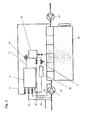
- thermochemical reactor 14 In the Fig. 3 schematically an internal combustion engine is shown with a thermochemical reactor 14 and the corresponding cable guides and leads.
- the thermochemical reactor 14, the various streams are fed via appropriate metering and mixing devices.
- line and metering valve 21 the main part of the intended for the Vorsch Hughes fuel gas is fed to the reactor.
- the remaining part passes through the gas-air guide 20 to the thermochemical reactor, with which the air content is supplied.
- the supply line 19 the amount of exhaust gas is introduced and provided via the line 22 of the required steam content.
- the product gas is compressed by compressor 15 to the pressure required to flush the prechambers and passed to a buffer volume 16.
- the required quantity ratio of the material flows depends, as already stated, on different parameters, for example on the engine load, the composition of the propellant gas and on the specific design and operation of the reforming device (for example temperature level and catalyst material).
- thermochemical reactor water vapor The introduced into the thermochemical reactor water vapor is only used up to a small extent chemically. The overwhelming part leaves the reformer with the reforming gas and is condensed out after the cooler and returned to the reform process in the cycle.
- About the ratio of the metered exhaust gas to be reformed propellant combustion behavior of the internal combustion engine can be influenced. With a higher proportion of exhaust gas combustion in the pre-chamber is cooler and the ignition pulse in the main combustion chamber weaker. Thus, for example, increases the burning time and thereby somewhat knock-resistant and the maximum cylinder pressure can be reduced at the expense of a slightly poorer efficiency of the internal combustion engine. This effect may be desirable, for example, for optimal adjustment of the combustion process of combustion gases with temporally variable knock resistance or Representation of temporary overload operation, for example for peak load coverage.
- the preferred solution further envisages that the operating state of the internal combustion engine detected by the engine management system and the gas composition determined by suitable gas sensors at the outlet of the reactor are used for metering the material flows into the reactor.
- sensors are used for the gas components hydrogen, carbon monoxide and carbon dioxide, whereby the measurement of CO 2 may already be sufficient.
- thermochemical reactor 14 a further or additional stream.
- This can be, for example, a combustible medium, for example a gaseous or liquid fuel, or else an external CO 2 source.
- thermochemical conversion in the thermochemical reactor 14 would result in unfavorable combustion properties in the antechambers.
- a relatively high-calorie reforming gas can be produced with good combustion properties
- purge gas fuels for example, diesel fuel or fuel oil, LPG (butane or propane) or biogenic fuels such as ethanol or methanol may be used.
- thermochemical process in the reactor it is advantageous to produce a larger amount of product gas in the reactor, as for flushing the prechambers is required, and to supply the excess amount to the engine together with the combustion air and with the main gas amount. This is done via line 23.
- the internal combustion engine 15 is a mixture-charged internal combustion engine with an exhaust-gas turbocharger.
- the exhaust gas turbocharger consists of an exhaust gas turbine and a compressor, which are connected to each other via a common shaft.
- the exhaust gas turbocharger compressor 41 on the one hand propellant gas and on the other hand opens air, and the output from the buffer memory 16.
- the control and regulation of the thermochemical process for generating purge gas of suitable composition is preferably a volume ratio of CO 2 to H2 in a range between 70:30 and 40:60 to minimize soot formation.
Landscapes
- Engineering & Computer Science (AREA)
- Chemical & Material Sciences (AREA)
- Combustion & Propulsion (AREA)
- Mechanical Engineering (AREA)
- General Engineering & Computer Science (AREA)
- Chemical Kinetics & Catalysis (AREA)
- Combustion Methods Of Internal-Combustion Engines (AREA)
- Output Control And Ontrol Of Special Type Engine (AREA)
Description
- Die Erfindung betrifft ein Verfahren zum Betreiben einer Brennkraftmaschine, insbesondere eines vorkammergezündeten Gas-Otto-Motors, wobei der Vorkammer von außen ein Gas-Gemisch als Spülgas zugeführt wird
- Die Erfindung ist zum Beispiel anwendbar bei einer Brennkraftmaschine, insbesondere einem vorkammergezündeten Gas-Otto-Motor, umfassend einen Brennraum, der einen Treibstoffeinlass und einen Treibstoffauslass aufweist, der in einen Abgastrakt mündet, wobei eine Vorkammer vorgesehen ist, in der eine Zündeinrichtung anordenbar ist, mit der ein Treibstoff-Luft-Gemisch in der Vorkammer zündbar ist, wobei ein Fluideinlass vorgesehen ist, der in die Vorkammer mündet.
- Bei ottomotorisch betriebenen Brennkraftmaschinen erfolgt die Zündung eines Treibstoff-Luft-Gemischs im Brennraum durch Zündeinrichtungen, wobei die Gemischentflammung meist durch einen Funkenüberschlag an den Elektroden einer Zündkerze eingeleitet wird. Insbesondere bei Gasmotoren, bei denen ein Treibgas-Luft-Gemisch entzündet wird, setzt man bei größeren Brennraumvolumina das Magerkonzept ein. Dies bedeutet, dass ein relativ großer Luftüberschuss vorhanden ist, wodurch bei maximaler Leistungsdichte und gleichzeitig hohem Wirkungsgrad des Motors die Schadstoffemission sowie die thermische Belastung der Bauteile möglichst gering gehalten wird. Die Zündung und Verbrennung sehr magerer Treibstoff-LuftGemische stellt dabei eine erhebliche Herausforderung für die Entwicklung bzw. den Betrieb moderner Hochleistungsgasmotoren dar.
- Ab einer gewissen Baugröße der Gasmotoren (meist etwa oberhalb von sechs Litern Hubraum) ist es erforderlich, Zündverstärker einzusetzen, um die entsprechend großen Flammwege in den Brennräumen der Zylinder in möglichst kurzer Zeit zu durchlaufen. Als solche Zündverstärker dienen üblicherweise Vorkammern, wobei das am Ende des Kompressionshubes hoch verdichtete Treibstoff-Luft-Gemisch in einem vom Hauptbrennraum des Zylinders abgeteilten relativ kleinen Nebenraum gezündet wird. Dabei wird ein Hauptbrennraum vom Arbeitskolben, der Zylinderlaufbuchse und dem Zylinderkopfboden begrenzt, wobei der Nebenraum (die Vorkammer) durch ein oder mehrere Überströmbohrungen mit dem Hauptbrennraum verbunden ist. Häufig werden solche Vorkammern während der Ladungswechselphase mit Treibgas gespült bzw. gefüllt, um das Treibstoff-Luft-Gemisch anzufetten und damit die Verflammungs- und Verbrennungseigenschaften zu verbessern. Dazu wird eine kleine Treibgasmenge von der Treibgaszuführung zum Hauptbrennraum abgezweigt und über eine geeignete, mit einem Rückschlagventil versehene Zufuhreinrichtung in die Vorkammer eingeleitet. Diese Treibgasmenge spült während des Ladungswechsels die Vorkammer und wird deshalb oft als Spülgas bezeichnet.
- Während der Kompressionsphase strömt das sehr magere Treibstoff-Luft-Gemisch des Hauptbrennraumes durch die Überströmbohrungen in die Vorkammer und vermischt sich dort mit dem Spülgas. Das Verhältnis von Treibstoff zu Luft im Gemisch wird in Form der Luftüberschusszahl λ angegeben. A = 1 bedeutet dabei, dass die im Gemisch vorhandene Luftmenge genau jener Menge entspricht, die erforderlich ist, um eine vollständige Verbrennung der Treibstoffmenge zu ermöglichen. Die Verbrennung erfolgt in einem solchen Fall stöchiometrisch. Große Gasmotoren, werden bei Volllast üblicherweise mager bei einem λ von ca. 1,9 bis 2,0 betrieben, das heißt die Luftmenge im Gemisch ist etwa doppelt so hoch der stöchiometrischen Luftmenge. Durch die Spülung der Vorkammer mit Treibgas ergibt sich nach Vermischung mit dem Treibgas-Luft-Gemisch aus dem Hauptbrennraum ein mittleres λ in der Vorkammer von ca. 0,8 bis 0,9. Damit ergeben sich optimale Entflammungsbedingungen und aufgrund der Energiedichte intensive, in den Hauptbrennraum austretende Zündfackeln, die zu einem raschen Durchbrennen des Treibstoff-Luft-Gemischs im Hauptbrennraum führen. Bei solchen λ-Werten erfolgt die Verbrennung allerdings auf maximalem Temperaturniveau, sodass auch die Wandtemperaturen im Vorkammerbereich entsprechend hoch sind.
- Aus der
DE 10 2008 015 744 A1 geht eine Brennkraftmaschine hervor, bei welcher einer Vorkammer Abgas zugeleitet wird. Aufgabe dieser Schrift ist es, Frühzündungen zu vermeiden, indem durch Einbringung von Abgas über eine separate Düse in die Vorkammer die Luftüberschusszahl λ soweit erhöht wird, dass das Gemisch nicht mehr zündfähig ist. Dies ist darauf zurückzuführen, dass es sich bei der hier gezeigten Vorkammer um eine Einrichtung zur Selbstzündung mit einer Glühzündeinrichtung handelt und bei solchen Systemen eine vorzeitige Zündung verhindert werden muss. - Die
DE 103 56 192 A1 hat es sich zur Aufgabe gemacht, zum Ausgleich von Schwankungen in der Gasqualität Wasserstoff zu verwenden. - Mit zunehmender Steigerung der Motorleistung sowie durch die Maßnahmen zur Steigerung des Wirkungsgrades kommt es vermehrt zu Rußbildung in der Vorkammer. Der daraus resultierende Rußgehalt im Motorabgas führt zur Beeinträchtigung des Wärmeübergangs im Abhitzekessel sowie zu Problemen bei der bestimmten Anwendung von Gasmotoren, beispielsweise zur CO2-Düngung von Gewächshäusern.
- Eine Möglichkeit zur Vermeidung der Rußbildung besteht darin, das Treibstoff-Luft-Gemisch in der Vorkammer abzumagern und durch einen leichten Sauerstoffüberschuss den freien Kohlenstoff zu oxidieren. Dabei ergeben sich jedoch andere Probleme, die damit zusammenhängen, dass überschüssiger Sauerstoff bei den sehr hohen Verbrennungstemperaturen knapp über A = 1 zur Heißkorrosion an kritischen Stellen in der Vorkammer, insbesondere an den Überströmbohrungen sowie an den Zündkerzenelektroden, führen kann.
- Aufgabe der vorliegenden Erfindung ist es, hier Abhilfe zu schaffen und die Rußbildung sowie die Heißkorrosion zu vermeiden:
- Diese Aufgabe wird gelöst durch ein Verfahren zum Betreiben einer Brennkraftmaschine gemäß Anspruch 1. Erfindungsgemäß wird der CO2-Gehalt des Spülgases (Gas-Luft-Gemisch) in der Vorkammer vor der Zündung in einer definierten Weise eingestellt, in der Regel aber erhöht. Zusätzlich wird dem Spülgas Wasserstoff beigemengt.
- Der CO2-Gehalt des Spülgases kann sich bevorzugt in einem Bereich größer als 0,039 % (390 ppm) und kleiner als ca. 30 % bewegen.
- Die Grenzen für den CO2-Gehalt im Spülgas können abhängig von der Motorleistung festgelegt werden, zum Beispiel oberhalb von 75 % Motorleistung ein CO2-Gehalt von mehr als 10 % und/oder unterhalb von 25 % Motorleistung ein CO2-Gehalt von weniger als 5 %.
- Der Lösungsvorschlag sieht vor, dass die Vorkammer mit Spülgas gespült wird, wobei durch eine geeignete Zusammensetzung des Spülgases das Verbrennungsverhalten des Gas-Luft-Gemischs in der Vorkammer in einer Weise beeinflusst wird, dass insbesondere die Rußbildung unterdrückt wird. Diese Eigenschaft kann dann erreicht werden, wenn dem Spülgas CO2 zugesetzt wird. Hierbei ist einerseits denkbar, dass CO2 als Reingas oder Gasgemisch mit einem entsprechenden CO2-Gehalt zugeführt wird. Andererseits wäre es aber auch denkbar, dass das CO2 aus dem Abgas der Brennkraftmaschine stammt. Insbesondere die Variante, das CO2 durch Abgasrückführung aus dem Abgas zu entnehmen, hat den Vorteil, dass keine gesonderte CO2-Quelle erforderlich ist.
- Die Steuerung oder Regelung des CO2-Gehalts kann durch die Motorsteuerung erfolgen.
- Um die Zündeigenschaften des Treibstoff-Luft-Gemischs allerdings nicht maßgeblich zu verschlechtern, ist es notwendig, zusätzlich zum CO2 eine bestimmte Menge H2 beizumischen. Dabei ist das Verhältnis von CO2 zu H2 vorteilhafterweise so einzustellen, dass die mit einer CO2-Erhöhung in der Regel verbundene Verschlechterung der Verbrennungseigenschaften des Gasgemischs in der Vorkammer kompensiert wird. Eine genaue Dosierung und Regelung der Zusammensetzung des Spülgases für einen optimalen Betrieb der Brennkraftmaschine ist daher günstig.
- Da eine eigene Versorgung der Brennkraftmaschine mit einem abgestimmten CO2- zu H2-Gemisch beispielsweise aus einem Gastank kostenaufwändig ist, kann vorteilhafterweise vorgesehen sein, dass durch thermochemische Veränderung eines Gemisches vorhandener Stoffströme eine ideale oder günstige Zusammensetzung des Spülgases hergestellt wird.
- Bei Gasmotoren vorhandene Stoffströme, die für diesen Zweck genutzt werden können, sind beispielsweise das Treibgas, die Ansaugluft und Motorabgas.
- Die geeignete thermochemische Veränderung der Gaszusammensetzung kann beispielsweise durch partielle Oxidation unter Beisein bestimmter Katalysatoren erzielt werden. Ein Nachteil der partiellen Oxidation für die vorgesehene Anwendung ist die hohe Bildungsrate von Kohlenmonoxid, die zu Lasten des gewünschten Kohlendioxids geht. Zur Beseitigung dieses Nachteils sowie zur Verbesserung der Einstellbarkeit der chemischen Reaktion und der Flexibilität der Einrichtung wird vorgeschlagen, einen geringen Teil des Motorabgases zusätzlich zum verwendeten Treibgas und zu einem bestimmten Luftanteil sowie zu einer Wasserdampfmenge als Eingangsstoff in den thermochemischen Reaktor zu verwenden. Der thermochemische Reaktor kann dabei ein Dampf-Reformer sein.
- Die optimale Zusammensetzung des Spülgases hängt unter anderem vom Lastzustand des Motors ab. Bei Volllast sollte das Verhältnis von CO2 zu H2 günstigerweise größer als 0,5 sein, bei Start und geringer Teillast kleiner als 0,5 sein.
- Mit der thermochemischen Einrichtung auf Basis der angeführten Eingangsstoffströme kann die gewünschte Zusammensetzung' dadurch erreicht werden, dass das λ für die partielle Oxidation sowie die Verhältnisse der Stoffströme von Gas, Luft, Wasserdampf und Abgas zueinander entsprechend abgestimmt werden. Da im Abgas ohnehin eine gewisse Wasserdampfmenge vorhanden ist, kann dadurch die Menge des extern erzeugten H2O-Dämpfes entsprechende reduziert werden.
- Die Verfahrensführung sowie die verwendeten Katalysatoren sind, wie dem Fachmann geläufig, auf den gewünschten Zweck auszulegen. Neben der partiellen Oxidation wären grundsätzlich auch andere Verfahren denkbar bzw. möglich, die zur gewünschten Gaszusammensetzung für das Spülgas führen.
- An Sensorik im Falle einer Regelung kann ein Sensor für CO2 ausreichend sein. Bevorzugt sind noch Sensoren für Wasserstoff und/oder Kohlenmonoxid vorhanden.
- Weitere Vorteile und Details werden unter Zuhilfenahme der nachfolgenden Figuren und Figurenbeschreibungen erläutert.
- Es zeigt:
- Fig. 1
- eine schematische Darstellung einer Brennkraftmaschine bzw. eines erfindungsgemäßen Verfahrens im Querschnitt,
- Fig. 2
- einen schematischen Aufbau eines thermochemischen Reaktors sowie
- Fig. 3
- einen schematischen Aufbau der Brennkraftmaschine samt Reaktor.
-
Fig. 1 zeigt im Querschnitt einen Zylinder einer Brennkraftmaschine in Form eines Gasmotors umfassend eine Zylinderlaufbuchse 3, in der ein Kolben verschiebbar gelagert ist. Zwischen Zylinderkopfboden 4, Zylinderlaufbuchse 3 und Kolben 2 wird der Hauptbrennraum 5 gebildet, in dem die Hauptmenge an Treibgas-Luft-Gemisch verbrannt wird. Hierfür wird durch Einlassventile, die nicht gezeigt sind, Treibstoff und Luft eingelassen. Im Zuge des Kompressionstaktes strömt ein Teil dieses Gemisches über die Überströmbohrungen 8 in die Vorkammer 1, in die eine Zündkerze 7 mündet. - Herkömmlicherweise kann hier auch noch eine zusätzliche Treibgaszufuhr vorgesehen sein. Beim Stand der Technik erfolgt anschließend die Zündung des Gemischs in der Vorkammer 1 über die Zündkerze 7. Über die Überströmbohrungen 8 treten Zündfackeln aus, die das verdichtete Treibstoff-Luft-Gemisch im Hauptbrennraum 5 zünden und den Arbeitstakt des Zylinders einleiten.
- Die Zuführung 6 ist dafür vorgesehen, ein Brenngas oder ein Brenngas-Luft-Gemisch gesondert vom Haupt-Gas/Luft-Gemisch der Vorkammer zuzuführen, wobei damit die Vorkammer größtenteils von den verbrannten Restgasen des vorangegangenen Arbeitstaktes freigespült wird.
- Erfindungsgemäß wird über diese, den Stand der Technik darstellende Spülgaszufuhr, zusätzlich zum Brenngas oder dem Brenngas-Luftgemisch eine definierte CO2-Menge zur Vermeidung der Rußbildung in die Vorkammer eingeleitet.
- In einer bevorzugten Ausführungsvariante ist die Zuführung 6 in die Vorkammer allerdings mit einem thermochemischen Reaktor gemäß
Fig. 2 , mit dem die erwünschte CO2-Menge aus dem Brenngas sowie weiteren Reaktanden erzeugt wird, verbunden. Der thermochemische Reaktor 14 hat einen Ausgang 30, der in die Zuführung 6 der Vorkammer 1 mündet. Weiters beinhaltet der thermochemische Reaktor Einlässe für Treibgas 32, Luft 33, Wasserdampf 34 und Motorabgas 35. Über einzelne Ventile, die steuerbar sind, können diese Zulässe bestimmte Mengen an Gas abgeben, die dann in den thermochemischen Reaktor 14 eingebracht werden. Den thermochemischen Reaktor 14 werden die an der Reaktion beteiligten Stoffströme an Treibgas, Luft, Wasserdampf und Motorabgas in getrennten, mit Dosiereinrichtungen versehenen Regel- und Steuerventilen versehenen Leitungen zugeführt. Nach Vermischung der Stoffströme erfolgt im Gegenstrom-Wärmetauscher 31 eine Erwärmung dieses Gemischs auf ca. 600 °C. Anschließend erfolgt in einer Vorreaktionskammer 9 eine Überhitzung auf ca. 850 °C. In der Vorreaktionskammer sind Katalysatoren beispielsweise aus Nickel vorgesehen. Bei dieser Temperatur gelangt das Gasgemisch anschließend in die Reformierstufe 10, wo weitere Reaktionsschritte ablaufen. Das aus der Reformierstufe 10 mit etwa 700 °C austretende Produktgas wird zurückgeleitet zum Gegenstrom-Wärmetauscher 31, wo es das eintretende Gemisch erwärmt. Nach der Kühlung wird das Produktgas verdichtet, getrocknet und den Vorkammern zugeführt. - Je höher der Wasserdampfanteil im Gasgemisch am Reaktoreintritt ist, desto stärker verlagert sich das Reaktionsgleichgewicht auf die Seite von H2 und CO2 zu Lasten von CO und desto geringer ist die Gefahr der Verrußung der Katalysatoroberfläche. Gleiches bewirkt die Abgasmenge. Das Abgas hat gegenüber der Verwendung von Wasserdampf neben den chemischen auch energetische Vorteile, sodass im Idealfall durch die Verwendung von Abgas auf die Zudosierung von Wasserdampf verzichtet werden kann.
- Das Motorabgas setzt sich üblicherweise zusammen aus den Komponenten Wasserdampf mit etwa 11 vol%, CO2 mit ca. 5 vol%, O2 mit ca. 10 vol%. Der Rest ist Stickstoff und andere Spurenkomponenten.
- Im Abgas sind Wasserdampf und Luft bereits vorhanden, sodass die entsprechenden Stoffströme über die Zufuhr 33, 34 reduziert werden können. Darüber hinaus kann das Abgas bei Brennkraftmaschinen mit einem Abgasturbolader vor der Abgasturbine bei hohem Druck und hoher Temperatur entnommen werden, wodurch sich erhebliche energetische Vorteile ergeben.
- Erfindungsgemäß hat es sich als günstig erwiesen, wenn die dem Reaktor 14 zugeführte Gasmenge etwa 1 bis 2 vol% der gesamten Treibgasmenge des Motors betragen. In Relation dazu beträgt die dem Reaktor zugeführte Abgasmenge etwa das 0 bis Zweifache dieses Gasvolumenstroms.
- In der
Fig. 3 ist schematisch eine Brennkraftmaschine dargestellt mit einem thermochemischen Reaktor 14 sowie den entsprechenden Leitungsführungen und Zuleitungen. Dem thermochemischen Reaktor 14 werden die verschiedenen Stoffströme über entsprechende Dosier- und Mischeinrichtungen zugeführt. Über Leitung und Dosierventil 21 wird der Hauptteil des für die Vorkammerspülung vorgesehenen Brenngases zum Reaktor geführt. Der restliche Teil gelangt über die Gas-Luft-Führung 20 zum thermochemischen Reaktor, mit der auch der Luftanteil zugeführt wird. Über die Zuführleitung 19 wird die Abgasmenge eingebracht und über die Leitung 22 der erforderliche Wasserdampfanteil bereit gestellt. Das Produktgas wird durch Verdichter 15 auf den zur Spülung der Vorkammern erforderlichen Druck verdichtet und zu einem Puffervolumen 16 geleitet. In diesem erfolgt eine Kondensatabscheidung 17 und die Weiterführung zu den Vorkammern sowie zu einem geringen Teil zum Motoreintritt vor einem Abgasturboladerverdichter. Der Wasserdampfanteil wird nach Verdampfung des Kondensats 18 in den Reaktor eingeleitet. - Das erforderliche Mengenverhältnis der Stoffströme hängt, wie bereits ausgeführt, von unterschiedlichen Parametern ab, zum Beispiel von der Motorlast, der Zusammensetzung des Treibgases sowie von der konkreten Ausführung und Betriebsweise der Reformiereinrichtung (zum Beispiel Temperaturniveau und Katalysatormaterial).
- Der in den thermochemischen Reaktor eingebrachte Wasserdampf wird nur zu einem geringen Teil chemisch aufgebraucht. Der überwiegende Teil verlässt mit dem Reformgas den Reformer und wird nach dem Kühler auskondensiert und dem Reformprozess im Kreislauf wieder zugeführt.
- Über das Verhältnis des zudosierten Abgases zum zu reformierenden Treibgas kann das Verbrennungsverhalten der Brennkraftmaschine beeinflusst werden. Bei höherem Abgasanteil wird die Verbrennung in der Vorkammer kühler und der Zündimpuls in den Hauptbrennraum schwächer. Damit kann zum Beispiel die Brenndauer erhöht und unter Inkaufnahme eines etwas schlechteren Wirkungsgrades der Brennkraftmaschine dadurch etwas klopffester und der maximale Zylinderdruck reduziert werden. Dieser Effekt kann wünschenswert sein, zum Beispiel zur optimalen Anpassung des Brennverlaufs an Brenngase mit zeitlich veränderlicher Klopffestigkeit oder zur Darstellung von zeitlich begrenztem Überlastbetrieb, zum Beispiel zur Spitzenlastabdeckung.
- Der bevorzugte Lösungsvorschlag sieht weiters vor, dass der vom Motormanagementsystem erfasste Betriebszustand der Brennkraftmaschine sowie die durch geeignete Gassensoren am Austritt des Reaktors ermittelte Gaszusammensetzung zur Dosierung der Stoffströme in den Reaktor herangezogen werden. Zur Messung der Gaszusammensetzung werden Sensoren für die Gaskomponenten Wasserstoff, Kohlenmonoxid und Kohlendioxid verwendet, wobei die Messung von CO2 bereits ausreichend sein kann.
- Neben den oben angeführten Stoffströmen kann darüber hinaus auch ein weiterer bzw. zusätzlicher Stoffstrom dem thermochemischen Reaktor 14 zugeführt werden. Dies kann beispielsweise ein brennbares Medium, zum Beispiel ein gasförmiger oder flüssiger Kraftstoff, oder auch eine externe CO2-Quelle sein.
- Die Zuführung eines separaten Brenngases erweist sich besonders dann als vorteilhaft, wenn ein sehr heizwertschwaches Brenngas als Haupttreibstoff für den Motor vorliegt. In diesen Fällen würde die Verwendung des Treibgases der Brennkraftmaschine als Ausgangsbasis für die thermochemische Stoffumwandlung im thermochemischen Reaktor 14 ungünstige Verbrennungseigenschaften in den Vorkammern ergeben. Durch Verwendung von heizwertstarken und zum Beispiel zur besseren Lagerhaltung in flüssiger Form vorliegenden Brennstoffen kann ein relativ heizwertstarkes Reformgas mit guten Verbrennungseigenschaften erzeugt werden
- Die Erzeugung eines optimal zusammengesetzten Spülgases, unabhängig von der Beschaffenheit des Haupt-Brenngases, ermöglicht eine deutlich bessere Nutzbarkeit von sehr heizwertschwachen Treibgasen. Als heizwertschwache Treibgase können zum Beispiel Gichtgas oder Hochofengase genannt werden. Als alternative Spülgastreibstoffe können beispielsweise Dieselkraftstoff oder Heizöl, LPG (Butan oder Propan) oder biogene Brennstoffe wie Ethanol oder Methanol verwendet werden.
- Zur Stabilisierung und einfacheren bzw. betriebssicheren Regelung und Steuerung des thermochemischen Prozesses im Reaktor ist es vorteilhaft, eine größere Produktgasmenge im Reaktor zu erzeugen, als zur Spülung der Vorkammern erforderlich ist, und die überschüssige Menge dem Motor zusammen mit der Verbrennungsluft und mit der Hauptgasmenge zuzuführen. Dies erfolgt über die Leitung 23.
- In der
Figur 3 ist erkennbar, dass es sich bei der Brennkraftmaschine 15 um eine gemischaufgeladene Brennkraftmaschine mit einem Abgasturbolader handelt. Der Abgasturbolader besteht aus einer Abgasturbine und einem Verdichter, die über eine gemeinsame Welle miteinander verbunden sind. In den Abgasturboladerverdichter 41 mündet einerseits Treibgas und andererseits Luft, sowie der Ausgang aus dem Pufferspeicher 16. Bei der Steuerung und Regelung des thermochemischen Prozesses zur Erzeugung von Spülgas mit geeigneter Zusammensetzung ist bevorzugt ein Volumenverhältnis von CO2 zu H2 in einem Bereich zwischen 70:30 und 40:60 anzustreben, um die Rußbildung minimal zu halten.
Claims (5)
- Verfahren zum Betreiben eines vorkammergezündeten Gas-Otto-Motors, wobei der Vorkammer von außen ein Gas-Gemisch als Spülgas zugeführt wird, dessen CO2-Gehalt gesteuert oder geregelt wird und wobei dem Spülgas zusätzlich Wasserstoff beigemengt wird.
- Verfahren nach Anspruch 1, dadurch gekennzeichnet, dass das CO2 ganz oder teilweise aus dem Abgas der Brennkraftmaschine stammt.
- Verfahren nach Anspruch 1, dadurch gekennzeichnet, dass das CO2 ganz oder teilweise in einem thermo-chemischen Reaktor erzeugt wird.
- Verfahren nach einem der Ansprüche 1 bis 3, dadurch gekennzeichnet, dass der Wasserstoff durch einen Dampf-Reforming-Prozess erzeugt wird.
- Verfahren nach Anspruch 4, dadurch gekennzeichnet, dass CO2 aus dem Abgas der Brennkraftmaschine gemeinsam mit Treibstoff dem Dampf-Reforming-Prozess zugeführt wird.
Applications Claiming Priority (2)
| Application Number | Priority Date | Filing Date | Title |
|---|---|---|---|
| AT5922010 | 2010-04-14 | ||
| PCT/AT2011/000095 WO2011127494A1 (de) | 2010-04-14 | 2011-02-28 | Verfahren zum betreiben einer brennkraftmaschine |
Publications (2)
| Publication Number | Publication Date |
|---|---|
| EP2558696A1 EP2558696A1 (de) | 2013-02-20 |
| EP2558696B1 true EP2558696B1 (de) | 2015-04-08 |
Family
ID=43856194
Family Applications (1)
| Application Number | Title | Priority Date | Filing Date |
|---|---|---|---|
| EP11711001.5A Active EP2558696B1 (de) | 2010-04-14 | 2011-02-28 | Verfahren zum betreiben einer brennkraftmaschine |
Country Status (4)
| Country | Link |
|---|---|
| US (1) | US20130055985A1 (de) |
| EP (1) | EP2558696B1 (de) |
| AT (1) | AT12303U1 (de) |
| WO (1) | WO2011127494A1 (de) |
Cited By (2)
| Publication number | Priority date | Publication date | Assignee | Title |
|---|---|---|---|---|
| WO2021232076A1 (en) | 2020-05-06 | 2021-11-25 | Innio Jenbacher Gmbh & Co Og | Internal combustion engine and a method for operating an internal combustion engine |
| WO2022109633A1 (en) | 2020-11-30 | 2022-06-02 | Innio Jenbacher Gmbh & Co Og | Internal combustion engine and a method for operating such an internal combustion engine |
Families Citing this family (17)
| Publication number | Priority date | Publication date | Assignee | Title |
|---|---|---|---|---|
| AT511338B1 (de) * | 2011-10-19 | 2012-11-15 | Ge Jenbacher Gmbh & Co Ohg | Brennkraftmaschine, insbesondere stationärer gasmotor, umfassend einen brennraum |
| AT511351B1 (de) * | 2011-10-19 | 2012-11-15 | Ge Jenbacher Gmbh & Co Ohg | Verfahren zum betreiben wenigstens einer vorkammergezündeten brennkraftmaschine |
| DE102012204649A1 (de) * | 2012-03-22 | 2013-09-26 | Volkswagen Aktiengesellschaft | Motoraggregat mit gasbetriebenen Verbrennungsmotor und Wasserstoffreformer und Verfahren zum Betreiben eines solchen Motoraggregats |
| DE102012021778B4 (de) * | 2012-11-06 | 2016-03-10 | Mtu Friedrichshafen Gmbh | Gemischaufgeladener Gasmotor und Verfahren zur Kompensation von Liefergradabweichungen in einem gemischaufgeladenen Gasmotor |
| US9739193B2 (en) * | 2013-07-19 | 2017-08-22 | V-GRID Energy Systems | Ignition system for low grade synthesis gas at high compression |
| PL223578B1 (pl) * | 2014-04-03 | 2016-10-31 | Sindtech Spółka Z Ograniczoną Odpowiedzialnością | Sposób i instalacja do dostarczania wody lub innej pary do powietrza wlotowego silnika wewnętrznego spalania |
| US9249746B2 (en) | 2014-06-04 | 2016-02-02 | Cummins Inc. | System and method for engine control using pre-chamber ignition |
| AT516490B1 (de) | 2014-12-19 | 2016-06-15 | Ge Jenbacher Gmbh & Co Og | Verfahren zum Betreiben einer funkengezündeten Brennkraftmaschine |
| AT516543B1 (de) | 2014-12-19 | 2021-01-15 | Innio Jenbacher Gmbh & Co Og | Verfahren zum Betreiben einer funkengezündeten Brennkraftmaschine |
| AT516717B1 (de) | 2015-05-26 | 2016-08-15 | Ge Jenbacher Gmbh & Co Og | Brennkraftmaschine |
| WO2017082953A1 (en) | 2015-11-11 | 2017-05-18 | Cummins Inc. | Charge-fed pre-chamber assembly |
| DE102019128111A1 (de) * | 2019-10-17 | 2021-04-22 | Volkswagen Aktiengesellschaft | Versorgung einer aktiven Vorkammer für aufgeladene Ottomotoren mit einer Luftentnahme nach einem Abgasturbolader |
| EP3865690B1 (de) * | 2020-02-17 | 2022-07-20 | Wärtsilä Finland Oy | Verfahren zur steuerung einer mit einem vorbrennraum ausgestatteten und gasbetriebenen hubkolbenbrennkraftmaschine sowie die brennkraftmaschine davon |
| US11268434B1 (en) * | 2020-08-20 | 2022-03-08 | Saudi Arabian Oil Company | Method and system for extending dilution limit of a prechamber spark ignition engine |
| JP7133819B1 (ja) | 2021-05-19 | 2022-09-09 | 飯田グループホールディングス株式会社 | 水素供給システム及び水素供給方法 |
| US11674464B2 (en) * | 2021-07-28 | 2023-06-13 | Ford Global Technologies, Llc | Methods and systems for engine cold-start |
| DE102023211152A1 (de) * | 2023-11-10 | 2025-05-15 | Volkswagen Aktiengesellschaft | Verbrennungsmotor sowie Verfahren zum Betreiben eines Verbrennungsmotors |
Family Cites Families (7)
| Publication number | Priority date | Publication date | Assignee | Title |
|---|---|---|---|---|
| DE3110511A1 (de) * | 1980-03-21 | 1982-03-11 | Escher/Foster Technology Ass., Inc., 48879 St. Johns, Mich. | "verfahren und vorrichtung zur thermochemischen wasserstoff-sauerstoff-verbrennungseinleitung" |
| US6230683B1 (en) * | 1997-08-22 | 2001-05-15 | Cummins Engine Company, Inc. | Premixed charge compression ignition engine with optimal combustion control |
| DE10356192A1 (de) | 2003-12-02 | 2005-07-07 | Deutz Ag | Gasmotor |
| JP2005240586A (ja) * | 2004-02-24 | 2005-09-08 | Nippon Steel Corp | 低温プラズマ装置とガスエンジンとの複合システム、およびエネルギー生成方法 |
| US7210467B2 (en) * | 2004-06-22 | 2007-05-01 | Gas Technology Institute | Advanced high efficiency, ultra-low emission, thermochemically recuperated reciprocating internal combustion engine |
| US7493884B2 (en) * | 2006-10-12 | 2009-02-24 | Caterpillar Inc. | Method and system for reducing pollutant emissions of an engine |
| DE102008015744B4 (de) | 2008-03-26 | 2010-04-01 | Man Diesel Se | Brennkraftmaschine und Verfahren zum Betreiben derselben |
-
2011
- 2011-02-28 EP EP11711001.5A patent/EP2558696B1/de active Active
- 2011-02-28 WO PCT/AT2011/000095 patent/WO2011127494A1/de not_active Ceased
- 2011-05-05 AT AT0804711U patent/AT12303U1/de not_active IP Right Cessation
-
2012
- 2012-10-11 US US13/649,181 patent/US20130055985A1/en not_active Abandoned
Cited By (5)
| Publication number | Priority date | Publication date | Assignee | Title |
|---|---|---|---|---|
| WO2021232076A1 (en) | 2020-05-06 | 2021-11-25 | Innio Jenbacher Gmbh & Co Og | Internal combustion engine and a method for operating an internal combustion engine |
| US12241401B2 (en) | 2020-05-06 | 2025-03-04 | Innio Jenbacher Gmbh & Co Og | Internal combustion engine and a method for operating an internal combustion engine |
| WO2022109633A1 (en) | 2020-11-30 | 2022-06-02 | Innio Jenbacher Gmbh & Co Og | Internal combustion engine and a method for operating such an internal combustion engine |
| EP4325030A2 (de) | 2020-11-30 | 2024-02-21 | Innio Jenbacher GmbH & Co OG | Brennkraftmaschine und verfahren zum betreiben einer solchen brennkraftmaschine |
| US12085030B2 (en) | 2020-11-30 | 2024-09-10 | Innio Jenbacher Gmbh & Co Og | Internal combustion engine and a method for operating such an internal combustion |
Also Published As
| Publication number | Publication date |
|---|---|
| US20130055985A1 (en) | 2013-03-07 |
| WO2011127494A1 (de) | 2011-10-20 |
| EP2558696A1 (de) | 2013-02-20 |
| AT12303U1 (de) | 2012-03-15 |
Similar Documents
| Publication | Publication Date | Title |
|---|---|---|
| EP2558696B1 (de) | Verfahren zum betreiben einer brennkraftmaschine | |
| AT511338B1 (de) | Brennkraftmaschine, insbesondere stationärer gasmotor, umfassend einen brennraum | |
| AT511351B1 (de) | Verfahren zum betreiben wenigstens einer vorkammergezündeten brennkraftmaschine | |
| EP0208136B1 (de) | Verfahren zum Betrieb einer Brennkraftmaschine | |
| EP1102949B1 (de) | Verfahren zur verwertung eines brennstoffs unter nutzung exothermer vorreaktionen in form einer kalten flamme | |
| DE2410644A1 (de) | Anordnungen an brennkraftmaschinen und/oder feuerungsanlagen bei methanol-betrieb | |
| DE2521257B2 (de) | Verfahren zum Betreiben einer mit Selbstzündung arbeitenden Einspritzbrennkraftmaschine | |
| DE2532259B2 (de) | Brennstoffzufuhrsystem für gemischverdichtende Brennkraftmaschinen | |
| DE112012006249B4 (de) | Verfahren zur Gestaltung eines Arbeitsflusses eines Kolbengasmotors mit Kerzenzündung | |
| DE102012204649A1 (de) | Motoraggregat mit gasbetriebenen Verbrennungsmotor und Wasserstoffreformer und Verfahren zum Betreiben eines solchen Motoraggregats | |
| EP3425185B1 (de) | Ottogasmotor | |
| EP2690158B1 (de) | Mehrstufiges verfahren zur herstellung eines wasserstoffhaltigen gasförmigen brennstoffs und wärmegasgeneratoranlage | |
| DE102013210116B3 (de) | Brennkraftmaschine und Verfahren zum Betreiben einer Brennkraftmaschine | |
| DE112017006444T5 (de) | Betrieb eines Verbrennungsmotors mit verbesserter Kraftstoffeffizienz | |
| DE10356192A1 (de) | Gasmotor | |
| DE102012017930A1 (de) | Verbrennungskraftmaschine und Verfahren zum Betreiben einer Verbrennungskraftmaschine | |
| DE102015215939B4 (de) | Verfahren zum Erzeugen einer Brennstoffzusammensetzung und zum Betreiben einer Brennkraftmaschine | |
| DE4315034A1 (de) | Mehrstufenprozeß zum Betrieb eines Zweitakt-Verbrennungsmotors und Zweitakt-Verbrennungsmotor-Anlage zur Durchführung des Prozesses | |
| DE102017106571A1 (de) | System zur Erzeugung von Synthesegas und zugehöriges Verfahren hierfür | |
| DE102005039296B4 (de) | Verfahren zum Betreiben eines Verbrennungsmotors | |
| EP1546525B1 (de) | Verbrennungskraftmaschine mit interner verbrennung | |
| DE2712056A1 (de) | Verbrennungsmotoranordnung mit einer einrichtung zum reformieren von als brennstoff verwendetem methanol | |
| DE102010034848B4 (de) | Zweistoff-Triebwerk | |
| WO2006045433A1 (de) | Verfahren und vorrichtung zur umwandlung von energie unter verwendung von biomasse | |
| AT5936U1 (de) | Verfahren zum betreiben einer mit brenngas als hauptbrennstoff betriebenen brennkraftmaschine |
Legal Events
| Date | Code | Title | Description |
|---|---|---|---|
| PUAI | Public reference made under article 153(3) epc to a published international application that has entered the european phase |
Free format text: ORIGINAL CODE: 0009012 |
|
| 17P | Request for examination filed |
Effective date: 20121002 |
|
| AK | Designated contracting states |
Kind code of ref document: A1 Designated state(s): AL AT BE BG CH CY CZ DE DK EE ES FI FR GB GR HR HU IE IS IT LI LT LU LV MC MK MT NL NO PL PT RO RS SE SI SK SM TR |
|
| DAX | Request for extension of the european patent (deleted) | ||
| GRAP | Despatch of communication of intention to grant a patent |
Free format text: ORIGINAL CODE: EPIDOSNIGR1 |
|
| INTG | Intention to grant announced |
Effective date: 20141103 |
|
| GRAS | Grant fee paid |
Free format text: ORIGINAL CODE: EPIDOSNIGR3 |
|
| RAP1 | Party data changed (applicant data changed or rights of an application transferred) |
Owner name: GE JENBACHER GMBH & CO OG |
|
| GRAA | (expected) grant |
Free format text: ORIGINAL CODE: 0009210 |
|
| AK | Designated contracting states |
Kind code of ref document: B1 Designated state(s): AL AT BE BG CH CY CZ DE DK EE ES FI FR GB GR HR HU IE IS IT LI LT LU LV MC MK MT NL NO PL PT RO RS SE SI SK SM TR |
|
| REG | Reference to a national code |
Ref country code: GB Ref legal event code: FG4D Free format text: NOT ENGLISH |
|
| REG | Reference to a national code |
Ref country code: CH Ref legal event code: EP |
|
| REG | Reference to a national code |
Ref country code: IE Ref legal event code: FG4D Free format text: LANGUAGE OF EP DOCUMENT: GERMAN |
|
| REG | Reference to a national code |
Ref country code: AT Ref legal event code: REF Ref document number: 720761 Country of ref document: AT Kind code of ref document: T Effective date: 20150515 |
|
| REG | Reference to a national code |
Ref country code: DE Ref legal event code: R096 Ref document number: 502011006527 Country of ref document: DE Effective date: 20150521 |
|
| REG | Reference to a national code |
Ref country code: NL Ref legal event code: T3 |
|
| REG | Reference to a national code |
Ref country code: NL Ref legal event code: T3 |
|
| REG | Reference to a national code |
Ref country code: LT Ref legal event code: MG4D |
|
| PG25 | Lapsed in a contracting state [announced via postgrant information from national office to epo] |
Ref country code: HR Free format text: LAPSE BECAUSE OF FAILURE TO SUBMIT A TRANSLATION OF THE DESCRIPTION OR TO PAY THE FEE WITHIN THE PRESCRIBED TIME-LIMIT Effective date: 20150408 Ref country code: PT Free format text: LAPSE BECAUSE OF FAILURE TO SUBMIT A TRANSLATION OF THE DESCRIPTION OR TO PAY THE FEE WITHIN THE PRESCRIBED TIME-LIMIT Effective date: 20150810 Ref country code: LT Free format text: LAPSE BECAUSE OF FAILURE TO SUBMIT A TRANSLATION OF THE DESCRIPTION OR TO PAY THE FEE WITHIN THE PRESCRIBED TIME-LIMIT Effective date: 20150408 Ref country code: NO Free format text: LAPSE BECAUSE OF FAILURE TO SUBMIT A TRANSLATION OF THE DESCRIPTION OR TO PAY THE FEE WITHIN THE PRESCRIBED TIME-LIMIT Effective date: 20150708 Ref country code: ES Free format text: LAPSE BECAUSE OF FAILURE TO SUBMIT A TRANSLATION OF THE DESCRIPTION OR TO PAY THE FEE WITHIN THE PRESCRIBED TIME-LIMIT Effective date: 20150408 |
|
| PG25 | Lapsed in a contracting state [announced via postgrant information from national office to epo] |
Ref country code: LV Free format text: LAPSE BECAUSE OF FAILURE TO SUBMIT A TRANSLATION OF THE DESCRIPTION OR TO PAY THE FEE WITHIN THE PRESCRIBED TIME-LIMIT Effective date: 20150408 Ref country code: RS Free format text: LAPSE BECAUSE OF FAILURE TO SUBMIT A TRANSLATION OF THE DESCRIPTION OR TO PAY THE FEE WITHIN THE PRESCRIBED TIME-LIMIT Effective date: 20150408 Ref country code: GR Free format text: LAPSE BECAUSE OF FAILURE TO SUBMIT A TRANSLATION OF THE DESCRIPTION OR TO PAY THE FEE WITHIN THE PRESCRIBED TIME-LIMIT Effective date: 20150709 Ref country code: IS Free format text: LAPSE BECAUSE OF FAILURE TO SUBMIT A TRANSLATION OF THE DESCRIPTION OR TO PAY THE FEE WITHIN THE PRESCRIBED TIME-LIMIT Effective date: 20150808 |
|
| REG | Reference to a national code |
Ref country code: DE Ref legal event code: R097 Ref document number: 502011006527 Country of ref document: DE |
|
| PG25 | Lapsed in a contracting state [announced via postgrant information from national office to epo] |
Ref country code: EE Free format text: LAPSE BECAUSE OF FAILURE TO SUBMIT A TRANSLATION OF THE DESCRIPTION OR TO PAY THE FEE WITHIN THE PRESCRIBED TIME-LIMIT Effective date: 20150408 Ref country code: DK Free format text: LAPSE BECAUSE OF FAILURE TO SUBMIT A TRANSLATION OF THE DESCRIPTION OR TO PAY THE FEE WITHIN THE PRESCRIBED TIME-LIMIT Effective date: 20150408 |
|
| PLBE | No opposition filed within time limit |
Free format text: ORIGINAL CODE: 0009261 |
|
| STAA | Information on the status of an ep patent application or granted ep patent |
Free format text: STATUS: NO OPPOSITION FILED WITHIN TIME LIMIT |
|
| PG25 | Lapsed in a contracting state [announced via postgrant information from national office to epo] |
Ref country code: CZ Free format text: LAPSE BECAUSE OF FAILURE TO SUBMIT A TRANSLATION OF THE DESCRIPTION OR TO PAY THE FEE WITHIN THE PRESCRIBED TIME-LIMIT Effective date: 20150408 Ref country code: SK Free format text: LAPSE BECAUSE OF FAILURE TO SUBMIT A TRANSLATION OF THE DESCRIPTION OR TO PAY THE FEE WITHIN THE PRESCRIBED TIME-LIMIT Effective date: 20150408 Ref country code: PL Free format text: LAPSE BECAUSE OF FAILURE TO SUBMIT A TRANSLATION OF THE DESCRIPTION OR TO PAY THE FEE WITHIN THE PRESCRIBED TIME-LIMIT Effective date: 20150408 Ref country code: RO Free format text: LAPSE BECAUSE OF NON-PAYMENT OF DUE FEES Effective date: 20150408 |
|
| 26N | No opposition filed |
Effective date: 20160111 |
|
| PG25 | Lapsed in a contracting state [announced via postgrant information from national office to epo] |
Ref country code: IT Free format text: LAPSE BECAUSE OF FAILURE TO SUBMIT A TRANSLATION OF THE DESCRIPTION OR TO PAY THE FEE WITHIN THE PRESCRIBED TIME-LIMIT Effective date: 20150408 |
|
| PG25 | Lapsed in a contracting state [announced via postgrant information from national office to epo] |
Ref country code: BE Free format text: LAPSE BECAUSE OF NON-PAYMENT OF DUE FEES Effective date: 20160229 Ref country code: SI Free format text: LAPSE BECAUSE OF FAILURE TO SUBMIT A TRANSLATION OF THE DESCRIPTION OR TO PAY THE FEE WITHIN THE PRESCRIBED TIME-LIMIT Effective date: 20150408 |
|
| PG25 | Lapsed in a contracting state [announced via postgrant information from national office to epo] |
Ref country code: LU Free format text: LAPSE BECAUSE OF FAILURE TO SUBMIT A TRANSLATION OF THE DESCRIPTION OR TO PAY THE FEE WITHIN THE PRESCRIBED TIME-LIMIT Effective date: 20160228 Ref country code: MC Free format text: LAPSE BECAUSE OF FAILURE TO SUBMIT A TRANSLATION OF THE DESCRIPTION OR TO PAY THE FEE WITHIN THE PRESCRIBED TIME-LIMIT Effective date: 20150408 |
|
| REG | Reference to a national code |
Ref country code: CH Ref legal event code: PL |
|
| GBPC | Gb: european patent ceased through non-payment of renewal fee |
Effective date: 20160228 |
|
| PG25 | Lapsed in a contracting state [announced via postgrant information from national office to epo] |
Ref country code: LI Free format text: LAPSE BECAUSE OF NON-PAYMENT OF DUE FEES Effective date: 20160229 Ref country code: CH Free format text: LAPSE BECAUSE OF NON-PAYMENT OF DUE FEES Effective date: 20160229 |
|
| REG | Reference to a national code |
Ref country code: FR Ref legal event code: ST Effective date: 20161028 |
|
| REG | Reference to a national code |
Ref country code: IE Ref legal event code: MM4A |
|
| PG25 | Lapsed in a contracting state [announced via postgrant information from national office to epo] |
Ref country code: GB Free format text: LAPSE BECAUSE OF NON-PAYMENT OF DUE FEES Effective date: 20160228 Ref country code: FR Free format text: LAPSE BECAUSE OF NON-PAYMENT OF DUE FEES Effective date: 20160229 Ref country code: IE Free format text: LAPSE BECAUSE OF NON-PAYMENT OF DUE FEES Effective date: 20160228 |
|
| PG25 | Lapsed in a contracting state [announced via postgrant information from national office to epo] |
Ref country code: SE Free format text: LAPSE BECAUSE OF FAILURE TO SUBMIT A TRANSLATION OF THE DESCRIPTION OR TO PAY THE FEE WITHIN THE PRESCRIBED TIME-LIMIT Effective date: 20150408 |
|
| PG25 | Lapsed in a contracting state [announced via postgrant information from national office to epo] |
Ref country code: MT Free format text: LAPSE BECAUSE OF FAILURE TO SUBMIT A TRANSLATION OF THE DESCRIPTION OR TO PAY THE FEE WITHIN THE PRESCRIBED TIME-LIMIT Effective date: 20150408 |
|
| PG25 | Lapsed in a contracting state [announced via postgrant information from national office to epo] |
Ref country code: SM Free format text: LAPSE BECAUSE OF FAILURE TO SUBMIT A TRANSLATION OF THE DESCRIPTION OR TO PAY THE FEE WITHIN THE PRESCRIBED TIME-LIMIT Effective date: 20150408 Ref country code: HU Free format text: LAPSE BECAUSE OF FAILURE TO SUBMIT A TRANSLATION OF THE DESCRIPTION OR TO PAY THE FEE WITHIN THE PRESCRIBED TIME-LIMIT; INVALID AB INITIO Effective date: 20110228 Ref country code: CY Free format text: LAPSE BECAUSE OF FAILURE TO SUBMIT A TRANSLATION OF THE DESCRIPTION OR TO PAY THE FEE WITHIN THE PRESCRIBED TIME-LIMIT Effective date: 20150408 |
|
| PG25 | Lapsed in a contracting state [announced via postgrant information from national office to epo] |
Ref country code: MK Free format text: LAPSE BECAUSE OF FAILURE TO SUBMIT A TRANSLATION OF THE DESCRIPTION OR TO PAY THE FEE WITHIN THE PRESCRIBED TIME-LIMIT Effective date: 20150408 Ref country code: TR Free format text: LAPSE BECAUSE OF FAILURE TO SUBMIT A TRANSLATION OF THE DESCRIPTION OR TO PAY THE FEE WITHIN THE PRESCRIBED TIME-LIMIT Effective date: 20150408 |
|
| PG25 | Lapsed in a contracting state [announced via postgrant information from national office to epo] |
Ref country code: BG Free format text: LAPSE BECAUSE OF FAILURE TO SUBMIT A TRANSLATION OF THE DESCRIPTION OR TO PAY THE FEE WITHIN THE PRESCRIBED TIME-LIMIT Effective date: 20150408 |
|
| PG25 | Lapsed in a contracting state [announced via postgrant information from national office to epo] |
Ref country code: AL Free format text: LAPSE BECAUSE OF FAILURE TO SUBMIT A TRANSLATION OF THE DESCRIPTION OR TO PAY THE FEE WITHIN THE PRESCRIBED TIME-LIMIT Effective date: 20150408 |
|
| PGFP | Annual fee paid to national office [announced via postgrant information from national office to epo] |
Ref country code: AT Payment date: 20210122 Year of fee payment: 11 |
|
| REG | Reference to a national code |
Ref country code: AT Ref legal event code: MM01 Ref document number: 720761 Country of ref document: AT Kind code of ref document: T Effective date: 20220228 |
|
| PG25 | Lapsed in a contracting state [announced via postgrant information from national office to epo] |
Ref country code: AT Free format text: LAPSE BECAUSE OF NON-PAYMENT OF DUE FEES Effective date: 20220228 |
|
| P01 | Opt-out of the competence of the unified patent court (upc) registered |
Effective date: 20230614 |
|
| PGFP | Annual fee paid to national office [announced via postgrant information from national office to epo] |
Ref country code: NL Payment date: 20250121 Year of fee payment: 15 |
|
| PGFP | Annual fee paid to national office [announced via postgrant information from national office to epo] |
Ref country code: DE Payment date: 20250122 Year of fee payment: 15 |
|
| PGFP | Annual fee paid to national office [announced via postgrant information from national office to epo] |
Ref country code: FI Payment date: 20250121 Year of fee payment: 15 |