EP2558283B1 - Solid-liquid separation device - Google Patents
Solid-liquid separation device Download PDFInfo
- Publication number
- EP2558283B1 EP2558283B1 EP12715221.3A EP12715221A EP2558283B1 EP 2558283 B1 EP2558283 B1 EP 2558283B1 EP 12715221 A EP12715221 A EP 12715221A EP 2558283 B1 EP2558283 B1 EP 2558283B1
- Authority
- EP
- European Patent Office
- Prior art keywords
- screw
- center axis
- axis line
- movable members
- eccentric cams
- Prior art date
- Legal status (The legal status is an assumption and is not a legal conclusion. Google has not performed a legal analysis and makes no representation as to the accuracy of the status listed.)
- Active
Links
Images


















Classifications
-
- B—PERFORMING OPERATIONS; TRANSPORTING
- B30—PRESSES
- B30B—PRESSES IN GENERAL
- B30B9/00—Presses specially adapted for particular purposes
- B30B9/02—Presses specially adapted for particular purposes for squeezing-out liquid from liquid-containing material, e.g. juice from fruits, oil from oil-containing material
- B30B9/12—Presses specially adapted for particular purposes for squeezing-out liquid from liquid-containing material, e.g. juice from fruits, oil from oil-containing material using pressing worms or screws co-operating with a permeable casing
- B30B9/121—Screw constructions
-
- B—PERFORMING OPERATIONS; TRANSPORTING
- B30—PRESSES
- B30B—PRESSES IN GENERAL
- B30B9/00—Presses specially adapted for particular purposes
- B30B9/02—Presses specially adapted for particular purposes for squeezing-out liquid from liquid-containing material, e.g. juice from fruits, oil from oil-containing material
- B30B9/12—Presses specially adapted for particular purposes for squeezing-out liquid from liquid-containing material, e.g. juice from fruits, oil from oil-containing material using pressing worms or screws co-operating with a permeable casing
-
- B—PERFORMING OPERATIONS; TRANSPORTING
- B01—PHYSICAL OR CHEMICAL PROCESSES OR APPARATUS IN GENERAL
- B01D—SEPARATION
- B01D29/00—Filters with filtering elements stationary during filtration, e.g. pressure or suction filters, not covered by groups B01D24/00 - B01D27/00; Filtering elements therefor
- B01D29/11—Filters with filtering elements stationary during filtration, e.g. pressure or suction filters, not covered by groups B01D24/00 - B01D27/00; Filtering elements therefor with bag, cage, hose, tube, sleeve or like filtering elements
- B01D29/31—Self-supporting filtering elements
- B01D29/35—Self-supporting filtering elements arranged for outward flow filtration
-
- B—PERFORMING OPERATIONS; TRANSPORTING
- B01—PHYSICAL OR CHEMICAL PROCESSES OR APPARATUS IN GENERAL
- B01D—SEPARATION
- B01D25/00—Filters formed by clamping together several filtering elements or parts of such elements
- B01D25/12—Filter presses, i.e. of the plate or plate and frame type
- B01D25/127—Filter presses, i.e. of the plate or plate and frame type with one or more movable filter bands arranged to be clamped between the press plates or between a plate and a frame during filtration, e.g. zigzag endless filter bands
-
- B—PERFORMING OPERATIONS; TRANSPORTING
- B01—PHYSICAL OR CHEMICAL PROCESSES OR APPARATUS IN GENERAL
- B01D—SEPARATION
- B01D29/00—Filters with filtering elements stationary during filtration, e.g. pressure or suction filters, not covered by groups B01D24/00 - B01D27/00; Filtering elements therefor
- B01D29/44—Edge filtering elements, i.e. using contiguous impervious surfaces
- B01D29/46—Edge filtering elements, i.e. using contiguous impervious surfaces of flat, stacked bodies
-
- B—PERFORMING OPERATIONS; TRANSPORTING
- B01—PHYSICAL OR CHEMICAL PROCESSES OR APPARATUS IN GENERAL
- B01D—SEPARATION
- B01D29/00—Filters with filtering elements stationary during filtration, e.g. pressure or suction filters, not covered by groups B01D24/00 - B01D27/00; Filtering elements therefor
- B01D29/50—Filters with filtering elements stationary during filtration, e.g. pressure or suction filters, not covered by groups B01D24/00 - B01D27/00; Filtering elements therefor with multiple filtering elements, characterised by their mutual disposition
- B01D29/52—Filters with filtering elements stationary during filtration, e.g. pressure or suction filters, not covered by groups B01D24/00 - B01D27/00; Filtering elements therefor with multiple filtering elements, characterised by their mutual disposition in parallel connection
-
- B—PERFORMING OPERATIONS; TRANSPORTING
- B01—PHYSICAL OR CHEMICAL PROCESSES OR APPARATUS IN GENERAL
- B01D—SEPARATION
- B01D29/00—Filters with filtering elements stationary during filtration, e.g. pressure or suction filters, not covered by groups B01D24/00 - B01D27/00; Filtering elements therefor
- B01D29/62—Regenerating the filter material in the filter
- B01D29/64—Regenerating the filter material in the filter by scrapers, brushes, nozzles, or the like, acting on the cake side of the filtering element
- B01D29/6469—Regenerating the filter material in the filter by scrapers, brushes, nozzles, or the like, acting on the cake side of the filtering element scrapers
- B01D29/6476—Regenerating the filter material in the filter by scrapers, brushes, nozzles, or the like, acting on the cake side of the filtering element scrapers with a rotary movement with respect to the filtering element
-
- B—PERFORMING OPERATIONS; TRANSPORTING
- B01—PHYSICAL OR CHEMICAL PROCESSES OR APPARATUS IN GENERAL
- B01D—SEPARATION
- B01D29/00—Filters with filtering elements stationary during filtration, e.g. pressure or suction filters, not covered by groups B01D24/00 - B01D27/00; Filtering elements therefor
- B01D29/76—Handling the filter cake in the filter for purposes other than for regenerating
- B01D29/80—Handling the filter cake in the filter for purposes other than for regenerating for drying
- B01D29/82—Handling the filter cake in the filter for purposes other than for regenerating for drying by compression
- B01D29/828—Handling the filter cake in the filter for purposes other than for regenerating for drying by compression using screws
-
- B—PERFORMING OPERATIONS; TRANSPORTING
- B30—PRESSES
- B30B—PRESSES IN GENERAL
- B30B9/00—Presses specially adapted for particular purposes
- B30B9/02—Presses specially adapted for particular purposes for squeezing-out liquid from liquid-containing material, e.g. juice from fruits, oil from oil-containing material
- B30B9/12—Presses specially adapted for particular purposes for squeezing-out liquid from liquid-containing material, e.g. juice from fruits, oil from oil-containing material using pressing worms or screws co-operating with a permeable casing
- B30B9/14—Presses specially adapted for particular purposes for squeezing-out liquid from liquid-containing material, e.g. juice from fruits, oil from oil-containing material using pressing worms or screws co-operating with a permeable casing operating with only one screw or worm
-
- B—PERFORMING OPERATIONS; TRANSPORTING
- B30—PRESSES
- B30B—PRESSES IN GENERAL
- B30B9/00—Presses specially adapted for particular purposes
- B30B9/02—Presses specially adapted for particular purposes for squeezing-out liquid from liquid-containing material, e.g. juice from fruits, oil from oil-containing material
- B30B9/12—Presses specially adapted for particular purposes for squeezing-out liquid from liquid-containing material, e.g. juice from fruits, oil from oil-containing material using pressing worms or screws co-operating with a permeable casing
- B30B9/16—Presses specially adapted for particular purposes for squeezing-out liquid from liquid-containing material, e.g. juice from fruits, oil from oil-containing material using pressing worms or screws co-operating with a permeable casing operating with two or more screws or worms
-
- B—PERFORMING OPERATIONS; TRANSPORTING
- B30—PRESSES
- B30B—PRESSES IN GENERAL
- B30B9/00—Presses specially adapted for particular purposes
- B30B9/02—Presses specially adapted for particular purposes for squeezing-out liquid from liquid-containing material, e.g. juice from fruits, oil from oil-containing material
- B30B9/26—Permeable casings or strainers
Definitions
- the present invention relates to a solid-liquid separation device/separator which includes a plurality of fixed members, a plurality of movable members that are disposed between the adjacent fixed members, and at least one screw extending through the fixed members and the movable members in a state where the screw is not in contact with the fixed members and the movable members, with this screw being rotationally driven about a center axis line thereof while an object to be treated that has penetrated into a solid-liquid separation portion demarcated by the fixed members and the movable members bring caused to move toward an outlet of the solid-liquid separation portion by rotation of the screw, and a filtrate separated from the object to be treated being discharged to the outside of the solid-liquid separation portion through filtrate discharge gaps between the fixed members and the movable members, and then the object to be treated that has a reduced water content ratio being discharged from the outlet to the outside of the solid-liquid separation portion.
- a solid-liquid separator of the above-described system in which a screw does not come into contact with movable members and fixed members is well known as one of solid-liquid separators suitable for separating a liquid from an object to be treated, for example, organic sludge such as soybean wastes, wastewater from food processing, sewage drainage, and wastewater discharged from hog farms, sludge obtained by decomposition of the aforementioned organic sludge with microorganisms, inorganic sludge such as waste liquid from plating, ink waste liquid, pigment waste liquid, and paint waste liquid, and also vegetable wastes, fruit peelings, food residues, and tofu refuse.
- organic sludge such as soybean wastes, wastewater from food processing, sewage drainage, and wastewater discharged from hog farms
- sludge obtained by decomposition of the aforementioned organic sludge with microorganisms inorganic sludge such as waste liquid from plating, ink waste liquid, pigment waste liquid, and paint waste liquid, and also
- JP-S59-218298-A discloses a screw-press dewatering apparatus in which a plurality of sliding plates disposed between fixed plates are integrally connected to each other, and a screw passes through holes in the fixed plates and the sliding plates.
- WO00/32292 A1 (page 5) describes a configuration in which a screw passes through an inner circumferential contour of a filtration tube in which fixed plates and movable plates are arranged alternately with mutual superposition, opening edges of the fixed plates form the inner circumferential contour, and the movable plates oscillate in a range in which the opening edges do not penetrate into the inner circumferential contour in the fixed plates.
- JP-2000-135595-A discloses a screw press device in which a screw passes inside a cylindrical space defined by the inner circumferential surface of a filtration tube having a large number of annular fixed plates arranged successively with gaps therebetween and a large number of annular movable plates arranged in corresponding gaps.
- movable members perform a movement such as a circular movement, a reciprocating linear movement, or a reciprocating inclined movement with respect to fixed members. Therefore, solids can be prevented from clogging the filtrate discharge gaps between the fixed members and the movable members. Moreover as the movable members are not in contact with the screw, the movable members can be prevented from being rapidly worn out.
- a problem associated with the solid-liquid separator of a contactless system is that the efficiency of liquid removal from the object to be treated is low and the object to be treated cannot be subjected to liquid removal treatment with good efficiency. A reason therefor has been unclear for a long time. The inventors have conducted comprehensive tests to clarify the reason for the aforementioned problem and clarified the following facts.
- JP-S59-218298-A describes the configuration in which the sliding plates perform a circular movement such that holes at both sides come into point contact.
- WO00/32292 A1 (page 5) describes the configuration in which the movable plates oscillate within a range in which the opening edges do not penetrate into the interior of the inner circumferential contour of the fixed plates.
- JP-2000-135595-A also describes the configuration in which the dimensions are set such that the opening edges of movable plates cannot narrow the inner circumferential surface of the tubular space determined by a row of openings of the fixed plates when the movable plates oscillate.
- the movable members thus oscillate outside the outer circumferential edge of the screw blade, the movable members do not come into contact with the screw and therefore the movable members are prevented from being rapidly worn out. Therefore, such an approach has been a common technical knowledge.
- the present invention is based on the above-described new information and it is an object thereof to provide a solid-liquid separator of a contactless system in which movable members can be prevented from being rapidly worn out and the efficiency of liquid removal from the object to be treated can be greatly increased.
- the present invention provides a solid-liquid separator of a contactless system according to the features of claim 1.
- the movable members do not come into contact with the screw and therefore the movable members can be prevented from being rapidly worn out. Furthermore, since at least part of the movable members move, while penetrating closer to the center axis line of the screw than the outer circumferential edge of the screw blade, these movable members that move, while penetrating closer to the center axis line of the screw, apply a large shear force as they penetrate so as to cut into the object to be treated that is conveyed by the rotating screw. As a consequence, the efficiency of liquid removal from the object to be treated is increased and the object to be treated can be subjected to liquid removal treatment with good efficiency.
- FIG. 1 is a front view, with a partial cross section, of a solid-liquid separator.
- FIG. 2 is a plan view of the solid-liquid separator. In this figure, the depiction of the below-describe fixed members and movable members is omitted.
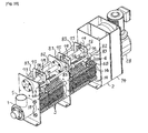
- FIG. 3 is a perspective view illustrating part of the solid-liquid separator.
- the solid-liquid separator shown in these figures is suitable for solid-liquid separation of various treatment objects including a liquid, but the explanation below will be performed with reference to the case in which a sludge including a large amount of water is dewatered.
- a solid-liquid separator of a contactless system shown in FIGS. 1 to 3 includes an inlet member 1 in which an inflow port 5 is formed in the upper portion and which is formed to have a hollow interior, an outlet member 2 having formed in the lower portion thereof a discharge port 11 for discharging a cake-like sludge obtained by dewatering, a plurality of fixed members 3 disposed between the outlet member 2 and the inlet member 1, and movable members 4 disposed between the adjacent fixed members 3. Each movable member 4 performs a circular movement as will be described hereinbelow.
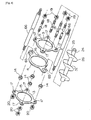
- FIG. 4 is an exploded perspective view illustrating two adjacent fixed members 3 and one movable member 4 disposed between these two fixed members 3.
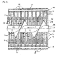
- FIG. 5 is an enlarged vertical sectional view illustrating some of a large number of fixed members 3 and movable members 4.
- the fixed members 3 and movable members 4 are arranged in the axial direction in mutually parallel postures.
- a plurality of fixed members 3 are disposed concentrically with a clearance in the axial direction, this arrangement being set by small ring-shaped spacers 14 disposed between the adjacent fixed members 3, and one movable member 4 is disposed between the adjacent fixed members 3.
- four spacers 14 are disposed between the adjacent fixed members 3.
- the fixed members 3 and the movable members 4 of the present embodiment are constituted by ring-shaped plates having round through holes 15, 16 formed therein.
- an opening 8 is formed in a side plate 7 of the inlet member 1 on the side facing the fixed members 3 and the movable members 4, and an opening 10 is formed in a side plate 9 of the outlet member 2 on the side facing the fixed members 3 and the movable members 4.
- a hollow solid-liquid separation portion 21 demarcated by the through holes 15, 16 of the fixed members and movable members is formed inside the fixed members 3 and the movable members 4.
- FIG. 1 an opening 8 is formed in a side plate 7 of the inlet member 1 on the side facing the fixed members 3 and the movable members 4
- an opening 10 is formed in a side plate 9 of the outlet member 2 on the side facing the fixed members 3 and the movable members 4.
- a hollow solid-liquid separation portion 21 demarcated by the through holes 15, 16 of the fixed members and movable members is formed inside the fixed members 3 and the movable
- the openings 8, 10 formed in the inlet member 1 and the outlet member 2 are positioned correspondingly to the through holes 15, 16 of the fixed members 3 and the movable members 4.
- the solid-liquid separation portion 21 is demarcated by the fixed members 3 and the movable members 4 inside the fixed members and the movable members, and as shown in FIG. 1 , the end portion of the solid-liquid separation portion 21 on the side of the inlet member 1 becomes an inlet port 22 of the solid-liquid separation portion 21, and the end portion on the side of the outlet member 2 becomes an outlet port 23 of the solid-liquid separation portion 21.
- the lower portion of the side plate 7 of the inlet member 1 is fixed to a stay 12 of a support frame, and the lower portion of the side plate 9 of the outlet member 2 is also fixed to a stay 13 of the support frame.
- each fixed member 3 As shown in FIGS. 4 and 5 , four attachment holes 17 are formed in each fixed member 3, and stay bolts 18 extend through the attachment holes 17 and central holes of spacers 14 disposed between the adjacent fixed members 3. As shown in FIG. 1 , these stay bolts 18 pass through the side plate 7 of the inlet member 1 and the side plate 9 of the outlet member 2, and nuts 19, 20 are screwed and tightened on the male threads formed at the end portions, in the longitudinal direction, of each stay bolt 18 (see also FIG. 3 ). As a result, a plurality of fixed members 3 is integrally fixed and connected to each other, and the fixed members 3 are also fixed to the inlet member 1 and the outlet member 2. In FIG.
- FIGS. 8A, 8B and FIGS. 9A, 9B are explanatory cross-sectional views clarifying the state in which the movable members 4 perform the circular movement as will be described hereinbelow, and these drawings make it possible to understand clearly the state of the fixed members 3, movable members 4, stay bolts 18, and spacers 14 when the solid-liquid separation portion 21 is viewed in the axial direction.
- a single screw 24 extending through the through holes 15, 16 of the fixed members 3 and the movable members 4 that demarcate the solid-liquid separation portion 21 is disposed in the aforementioned solid-liquid separation portion 21.
- the screw 24 has a single blade 26 extending spirally and a shaft 25 formed integrally with the blade 26.
- the shaft 25 constitutes the central portion of the screw 24, and the center axis line X ( FIGS. 2 , 5 , 8 , and 9 ) of the shaft 25 becomes the center axis line of the screw 24 itself.
- the outer circumferential edge 32 of the blade 26 of the screw 24 has a circular shape.
- a plurality of fixed members 3 and movable members 4 of the solid-liquid separator of the present embodiment have through holes 15, 16 formed therein, and the screw 24 extends through the through holes 15, 16 of the fixed members 3 and the movable members 4.
- the fixed members 3 that are spaced from each other by spacers 14 can be assembled so as to allow a very small play thereof. It is also possible to form the spacer integrally with one fixed member of the two adjacent fixed members, form by this spacer a gap between two adjacent fixed members, and dispose the movable member 4 in the gap. Further, in the solid-liquid separator shown in FIGS. 1 to 5 , one movable member 4 is disposed between the two adjacent fixed members 3, but a plurality of movable members 4 can be also disposed between the adjacent fixed member 3. At least one movable member 4 is disposed between the fixed members 3 adjacent in the axial direction.
- the thickness T of each movable member 4 disposed between the fixed members 3 is set to be less than the gap width "G" between the fixed members, and a very small filtrate discharge gap "g", for example, of about 0.1 mm to 1 mm is formed between the end surface of each fixed member 3 and the end surface of the movable member 4 corresponding thereto.
- These very small filtrate discharge gaps "g” serve to allow the water separated from the sludge in the below-described manner, that is, the filtrate, to pass therethrough.
- the thickness T of the movable member 4 is set, for example, to about 1.0 mm to 3 mm, and the gap width G to about 1.2 mm to 5 mm, for example.
- the thickness t of the fixed member 3 is set, for example, to about 1.5 mm to 3 mm.
- the values of the very small filtrate discharge gap "g", thicknesses "T” and “t”, and gap width "G" are set as appropriate with consideration for the type of the object to be treated.
- the end portion of the shaft 25 of the screw 24 on the side of the outlet member 2 is drivably connected to a drive unit constituted by an electric motor 28 equipped with a reducer that is fixed to and supported by a side plate 27 on the other side of the outlet member 2.
- the portion of the shaft 25 on the side of the inlet member 1 is rotatably supported by a bearing 55 at a side plate 29 on the other side of the inlet member 1.
- the drive unit constituted by the electric motor 28 serves to drive rotationally the screw 24 about the center axis line X thereof.
- the outer diameter of the blade 26 of the screw 24 is set to be less than the diameter of the circular through hole 15 formed in the fixed member 3. Furthermore, even when the movable members 4 perform the circular movement, as will be described hereinbelow, the screw 24 does not come into contact with the inner circumferential surfaces of the through holes 16 formed in the movable members 4 and openings 8, 10 formed in the side plates 7, 9.
- the solid-liquid separator of the present embodiment is provided with the screw 24 extending through the movable members 4 and the fixed members 3, without being in contact with the movable members 4 and the fixed members 3, and the drive unit that rotationally drives the screw 24 about the center axis line X thereof.
- the sludge including a large amount of water flows from the inflow port 5 into the inlet member 1.
- the content ratio of water in the sludge before the treatment is, for example, about 99 wt%.
- a flocculant has been admixed to the sludge in advance and the sludge has been flocculated.
- the screw 24 is rotated by the operation of the electric motor 28 about the center axis line X of the screw.
- the sludge passes through the opening 8 formed in the side plate 7 of the inlet member 1 and flows into the solid-liquid separation portion 21 constituted by the fixed members 3 and the movable members 4, as shown by arrow B in FIG. 1 .
- the sludge flows into the solid-liquid separation portion 21 from the inlet port 22 at one end side in the axial direction thereof.
- the depiction of the sludge in the figure is omitted.
- the sludge that has flown into the solid-liquid separation portion 21 as described hereinabove is conveyed toward the outlet 23 at the other end side in the axial direction of the solid-liquid separation portion 21, as shown by arrow C in FIGS. 1 and 5 , by the screw 24 that is rotationally driven by the electric motor 28.
- the water separated from the sludge, that is, the filtrate is discharged to the outside of the solid-liquid separation portion 21 through the filtrate discharge gaps "g" ( FIG. 5 ) between the fixed members 3 and the movable members 4.
- the discharged filtrate is received by a filtrate receiving member 30 (not shown in FIG. 2 ) fixed to the stays 12, 13, as shown in FIG. 1 , and then flows down through a filtrate discharge tube 31.
- the content ratio of water in the sludge inside the solid-liquid separation portion 21 is thus reduced, and the cake-like sludge with reduced content of water is discharged from the outlet 23 on the other end side in the axial direction of the solid-liquid separation portion 21 as shown by arrow D in FIG. 1 .
- the sludge discharged from the solid-liquid separation portion 21 falls down through the discharge port 11 located in the lower portion of the outlet member 2.
- the content ratio of water in the treated cake-like sludge is, for example, about 75 to 80 wt%.
- the solid-liquid separator of the present embodiment is provided with following configuration in order to prevent the filtrate discharge gaps "g" ( FIG. 5 ) between the fixed members 3 and the movable members 4 form being clogged by solids when the sludge is thus dewatered.
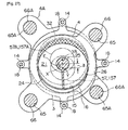
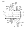
- an eccentric cam 57 in which an outer circumferential surface 58 is formed to have a round shape is detachably attached, so as to be capable of rotating integrally with the shaft 25 of the screw 24, by a key 56 ( FIG. 7 ) fitted in a key groove to one end portion of the shaft 25 of the screw 24.
- a key 56 FIG. 7
- the center axis line Y of the eccentric cam 57 is offset by a distance represented by (delta) with respect to the center axis line X of the shaft 25 of the screw 24, and the round outer circumferential surface 58 of the eccentric cam 57 is mated with a round cam hole 60 of a bearing 59 constituted by a sliding bearing.
- the round outer circumferential surface 58 of the eccentric cam 57 slidably abuts, directly or with a lubricant located therebetween, on the inner circumferential surface of the round cam hole 60 of the bearing 59.
- the aforementioned bearing 59 is mated with an attachment hole 62 of the connection plate 61, and this bearing 59 is detachably attached, as shown in FIGS. 3 and 6 , to the connection plate 61 with a bolt (not shown in the figure) and a nut (also not shown in the figure) that is screwed on this bolt and tightened.
- the bearing 59 of the present embodiment is thus fixed to the connection plate 61, but the bearing 59 can be also rotatably fitted into the attachment hole 62 formed in the connection plate 61.
- the connection plate 61 is connected to the bearing 59 in a manner such that the connection plate 61 can perform the below-described circular movement.
- the above-described eccentric cam 57 and the bearing 59 mated with the eccentric cam 57 are provided at the shaft 25 of the screw 24 on the side of the inlet member 1.
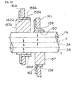
- an eccentric cam 157, a bearing 159, and a connection plate 161 configured similarly to the above-described eccentric cam 57, bearing 59, and connection plate 61 are also provided at the portion of the shaft 25 on the side of the outlet member 2.
- the center axis lines Y of the two eccentric cams 57, 157 coincide, and the eccentricity (delta) of the eccentric cams 57, 157 with respect to the center axis line X of the screw 24 is the same.
- the eccentric cams 57, 157, the bearings 59, 159 mated with the eccentric cams 57, 157, and the connection plates 61, 161 are provided by one each at each portion of the shaft 25 on the outside, in the longitudinal direction, of the blade 26 of the screw 24.
- attachment holes 64, 164 are formed in the pair of respective connection plates 61, 161 having the respective bearings 59, 159 fixed therein, at a ratio of two attachment holes per one connection plate.
- two attachment holes 65 are also formed in each of the plurality of movable members 4.
- a pair of connecting rods 66 (see also FIGS. 8 and 9 ) disposed symmetrically with respect to the center axis line X of the screw 24 pass through these attachment holes 64, 164, 65, and nuts 67, 167 are screwed and tightened on the male threaded portions formed on each end, in the longitudinal direction, of each connecting rod 66.
- a pair of connecting rods 66 also extends through the side plate 7 of the inlet member and the side plate 9 of the outlet member 2. In FIG. 1 , only the end portions, in the longitudinal direction, are shown with respect to the connecting rod 66.
- the connecting rods 66 of the present embodiment are fixedly connected to the connection plates 61, 161, but the connecting rods 66 can be also loosely connected to the connection plates 61, 161.
- connection plates 61, 161 are connected by the pair of connecting rods 66, and a large number of movable members 4 are installed at the two connecting rods 66.
- Each connecting rod 66 may be tightly inserted, without a gap, into the attachment hole 65 of each movable member 4 and the connecting rod 66 may be fixedly connected to each movable member 4, or the connecting rod 66 may be mated with the attachment hole 65, so that a certain gap remains therebetween.
- three or more connecting rods may be provided.
- connection plates 61, 161 and a plurality of connecting rods 66 constitute connection means for connecting a plurality of movable members 4, and the bearings 59, 159 are respectively connected to the connection plates 61, 161 of this connection means.
- FIGS. 8 and 9 are cross-sectional views that clarify the relationship between the screw 24, movable members 4, and fixed members 3 (in the figures, the eccentric cams 57, 157 are additionally shown by virtual lines).
- the center axis line of the through holes 16 of the movable members 4 of the present embodiment coincides with the center axis line Y of the eccentric cams 57, 157.
- the center axis line of the through holes 16 is also denoted by the reference symbol Y.
- the center axis line Y of the through hole 16 of the movable member 4 of the present embodiment is offset by the eccentricity (delta) with respect to the center axis line X of the shaft 25 of the screw 24.
- the center axis line Y of the eccentric cams 57, 157 is also the center of the circle forming the outer circumferential surfaces 58, 158 thereof, and the center axis lines of the below-described eccentric cams are likewise also the centers of round outer circumferential surfaces thereof.
- the solid-liquid separator of the present embodiment is configured such that a plurality of movable members 4 can together perform a circular movement in the below-described manner. Therefore, the solid-liquid separator of the present embodiment includes the connection means for connecting a plurality of movable members 4, the eccentric cams 57, 157 that are decentered from the center axis line X of the shaft 25 of the screw 24 and rotate integrally with the shaft 25, and the bearings 59, 159 that are connected to the above-mentioned connection means and provided with round cam holes 60, 160 mating with the round outer circumferential surfaces 58, 158 of the eccentric cams 57, 157.
- the eccentric cams 57, 157 and the bearings 59, 159 mated with the eccentric cams 57, 157 are provided by one each at each portion of the shaft 25 on the outside, in the longitudinal direction, of the blade 26 of the screw 24.
- the connection means has a pair of connection plates 61, 161 connected to the bearings 59, 159, respectively, and a plurality of connecting rods 66 connected to a plurality of movable members 4, and the connecting rods 66 are connected to respective connection plates 61, 161.
- the center axis line of the through holes 16 of the movable members 4 and the center axis line of the eccentric cams 57, 157 coincide, and the center axis line Y of all of the movable members 4 also coincide.
- a configuration can be also used in which the center axis lines Y of the through holes 16 of the movable members 4 do not coincide, or the center axis line of the through holes 16 of the movable members 4 does not coincided with the center axis line of the eccentric cams 57, 157 and these center axis lines are decentered from each other.
- the through holes 16 can be formed in a shape other than the round shape, and the through holes 16 can be also formed in a shape in which the center axis line of the through hole 16 is not defined.
- the eccentric cams 57, 157 rotate following the rotation of the screw 24, while the center axis line Y of the eccentric cams 57, 157 describes a circle with a radius equal to the eccentricity (delta) of the eccentric cams 57, 157 about the center axis line X of the shaft 25 of the screw 24, as shown by arrow E in FIG. 7 .
- the eccentric cams 57, 157 are connected to the connection plates 61, 161
- the plurality of movable members 4 are connected by the plurality of connecting rods 66 to the connection plates 61, 161
- the center axis line of the eccentric cams 57, 157 and the center axis line of the through holes 16 of the plurality of movable members 4 connected by the connection means coincide, as shown by the reference symbol Y representing both center axis lines.
- connection means constituted by the connection plates 61, 161 and the connecting rods 66 and the plurality of movable members 4 connected by the connection means perform a circular movement with a radius equal to the eccentricity (delta) of the eccentric cams 57, 157.
- the movable members 4 connected by the connection means also perform a circular movement such that the center axis line Y of the through holes 16 describes a circle with a radius equal to the eccentricity (delta) of the eccentric cams about the center axis line X of the shaft 25 of the screw 24 in the order shown in FIGS. 8A, 8B , 9A, and 9B .
- the center axis line of the through holes 16 of the movable members 4 coincides with the center axis line of the eccentric cams 57, 157, and the center axis lines Y of the through holes 16 of all of the movable members 4 also coincide.
- the movable members 4 also perform a circular movement with a radius equal to the eccentricity (delta) of the eccentric cams 57, 157 when, by contrast with the above-described configuration, the center axis line of the through holes 16 of the movable members 4 and the center axis line of the eccentric cams 57, 157 do not coincide, or the center axis lines of the through holes 16 of the movable members 4 do not coincide with each other, and also when the center axis line of the through hole 16 of the movable member is not defined.
- the movable members 4 are connected to the eccentric cams 57, 157 so that in any of the cases the movable members 4 perform a circular movement with a radius equal to the eccentricity (delta) of the eccentric cams 57, 157.
- the movable members 4 perform a circular movement in the aforementioned manner, whereas the fixed members 3 remain immovable. Therefore, the solid matter that has penetrated into the filtrate discharge gaps "g" ( FIG. 5 ) between the mutually adjacent movable members 4 and the fixed members 3 is effectively discharged from the gaps g and the gaps are prevented from the being clogged by the solid matter. Further, since the blade 26 of the rotating screw 24 does not come into contact not only with the fixed members 3, but also with the movable members 4, the movable members 4 can be prevented from being rapidly worn out.
- the eccentric cams 57, 157 rotate so that the round outer circumferential surfaces 58, 158 thereof slide along the inner circumferential surfaces of the round cam holes 60, 160 of the bearings 59, 159, the eccentric cams 57, 157 or the bearings 59, 159, or both the eccentric cams and the bearings unavoidably wear out with time, but the amount of this wear is reduced in the following manner.
- the round outer circumferential surfaces 58, 158 of the eccentric cams 57, 157 come into contact, directly or with a lubricant being interposed therebetween, with the inner circumferential surfaces of the round cam holes 60, 160 of the bearings 59, 159 over the entire circumference thereof.
- the external force acting upon the round outer circumferential surfaces 58, 158 of the eccentric cams 57, 157 and the inner circumferential surfaces of the round cam holes 60, 160 of the bearings 59, 159 is dispersed and the contact pressure per unit surface area of both circumferential surfaces is low.
- connection plates 61, 161 are driven by the eccentric cams 57, 157 fixed to the shaft 25 of the screw 24, rather than by the pair, left and right, of eccentric cams, although the round outer circumferential surfaces 58, 158 of the eccentric cams 57, 157 and the inner circumferential surfaces of the round cam holes 60, 160 of the bearings 59, 159 are in contact with each other over the entire circumference, the connection plates 61, 161 can be caused to perform an accurate circular movement even when the shape accuracy or installation accuracy of the eccentric cams 57, 157 and bearings 59, 159 is not that high.
- connection plates 61, 161, connecting rods 66, and movable members 4 rotate (revolve) in the direction shown by arrow F in FIG. 8A about the center axis line X of the screw 24 under the effect of the external force applied to the connection plates 61, 161 of the connection means from the eccentric cams 57, 157, and the movable members 4 can abut on and damage the fixed members 3 or spacers 14 located between the fixed members. Accordingly, in the solid-liquid separator of the present embodiment, as shown in FIGS. 2 and 3 , ring-shaped guides 69 (not shown in FIG.
- the connecting rod 66 performs the aforementioned circular movement, the connecting rod 66 is guided while sliding along the inner circumferential surface of the ring-shaped guides 69, and the connecting rod 66 is prevented from rotating in the direction of arrow F shown in FIG. 8A .
- the guides 69 are used to cause the connection means to rotate together with the plurality of movable members 4 connected by this connection means in the direction of arrow F around the center axis line X of the shaft 25 of the screw 24 and to prevent the movable members 4 from abutting on other members.
- the eccentric cams 57, 157 are constituted as members separate from the screw 24, but the eccentric cams 57, 157 can be also formed integrally with the screw 24. Further, where the eccentric cams 57, 157 are detachably attached to the shaft 25 of the screw 24, as in the present embodiment, the eccentric cams 57, 157 can be taken off from the shaft 25 when the eccentric cams are worn out and new eccentric cams can be easily mounted on the shaft 25.
- a single screw 24 is used that has a single blade 26.
- a screw having two or more blades or to use two or more screws extending through the fixed members and movable members, as described in JP-4374396-B 1 .
- the fixed members and movable members constituted by plates having recesses formed in the upper portions thereof as described in JP-4374396-B 1 .
- at least one screw extending through the fixed members and movable members without coming into contact with the fixed members and movable members.
- the movable members 4 disposed between the adjacent fixed members are configured to perform a rotational movement, while maintaining the posture parallel to the fixed members 3, this movement being such that the center axis line Y of the through holes 16 thereof describes a circle around the center axis line X of the screw 24, but it is well-known that the movable members can be also configured to perform a reciprocating linear movement or reciprocating tilted movement, while maintaining the posture parallel to the fixed members (see JP-S59-218298-A , WO00/32292 A1 , JP-2000-135595-A , JP-2005-230852-A , and JP-4036383-B2 , and JP-4374396-B1 ). Further, configurations described in these patent documents or other well-known configurations can be used as appropriate for driving the movable members. These specific configurations will be described hereinbelow in greater detail.
- the solid-liquid separator in accordance with the present invention includes a plurality of fixed members, movable members that are disposed between the adjacent fixed members and can move, and at least one screw extending through the fixed members and the movable members in a state without contact with the fixed members and the movable members, and this solid-liquid separator is configured such that the screw is rotationally driven about a center axis line thereof, while the object to be treated that has penetrated into a solid-liquid separation portion demarcated by the fixed members and the movable members is caused to move toward an outlet of the solid-liquid separation portion by rotation of the screw, a filtrate separated from the object to be treated is discharged to the outside of the solid-liquid separation portion through filtrate discharge gaps between the fixed members and the movable members, and the object to be treated that has a reduced water content ratio is discharged from the outlet to the outside of the solid-liquid separation portion.
- This basic configuration is common to the below-described solid-liquid separators of various forms.
- the drawback of the conventional solid-liquid separators of this system is that the movable members that move with respect to the fixed members are configured such that the movable members move at all times on the outside of the outer circumferential edge of the screw, thereby inevitably causing the decrease in efficiency of liquid removal from the object to be treated.
- the movable members are formed to move, while penetrating closer to the center axis line of the screw than an outer circumferential edge of the screw blade, without coming into contact with the screw.
- the movable members that move, while penetrating closer to the center axis line of the screw apply a shear force to the object to be treated that is conveyed by the rotating screw, as they penetrate so as to cut into the sludge. Therefore, the efficiency of liquid removal from the object to be treated is greatly improved.
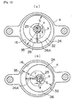
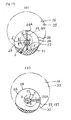
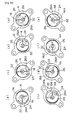
- FIGS. 8A, 8B , 9A, and 9B are cross-sectional views illustrating the circular movement of the movable member 4.
- the portion denoted by the reference symbol 26A represents the cross section of the blade 26 extending spirally.
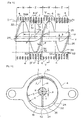
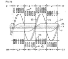
- FIG. 10 corresponds to a cross-sectional view obtained by cutting along the III-III line in FIG. 8A .
- FIG. 8A corresponds to a cross-sectional view taken along the IV-IV line in FIG. 10.
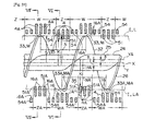
- FIG. 10 illustrates the relationship between movable members 4 and the screw 24, and in this figure the relative positions of the movable members 4 and the screw 24 and the screw shape do not perfectly match those shown in FIG. 5 (the same is true for FIGS. 15, 16 , 31 , and 33 ).
- Oblique hatching provided in FIGS. 8 and 9 represents a portion of the movable member 4 that penetrates closer to the center axis line X of the screw 24 than the outer circumferential edge 32 of the blade 26 of the screw 24.
- this portion of the movable member 4 that penetrates closer to the center axis line X of the screw 24 than the outer circumferential edge 32 of the blade 26 of the screw 24 is denoted by the reference numeral 51.
- this portion 51 of the movable member 4 that penetrates closer to the center axis line X of the screw 24 than the outer circumferential edge 32 of the blade 26 of the screw 24 is positioned between two adjacent blade portions 33 so as to avoid interference with the blade 26 of the screw 24.
- a portion 52 of the movable member 4 positioned on the side opposite that of the portion 51 of the movable member 4 with respect to the center line X of the screw 24, as shown in FIG. 8A and FIG. 10 another portion 34 of the blade 26 is positioned closer to the movable member portion 52.
- the movable member portion 52 is set apart from the blade portion 34 of the screw 24 in the radial direction thereof, the blade portion 34 does not interfere with the blade 26 of the screw 24.
- Clarified hereinbelow are the conditions that allow the movable member 4 to penetrate closer to the center axis line X of the screw 24 than the outer circumferential edge 32 of the blade 26 of the screw 24, without interfering with the blade 26 of the screw 24.
- FIG. 11 is an enlarged explanatory cross-sectional view in which the screw 24 and the movable member 4 shown in FIG. 8A are taken out to facilitate the understanding of the drawings.
- the shortest distance from the center axis line Y of the through hole 16 of the movable member 4 to a circumferential edge 35 of the movable member 4 that demarcates the through hole 16 is denoted by K
- the radius of the screw 24 is denoted by S
- the distance through which the center axis line Y of the through hole 16 is decentered from the center axis line X of the screw 24, that is, the eccentricity thereof, is denoted by (delta) as described hereinabove.
- the shortest distance K is the radius of the round through hole 16.
- the through hole 16 of the movable member 4 that performs a circular movement, while penetrating closer to the center axis line X of the screw 24 than the outer circumferential edge 32 of the blade 26 of the screw 24, is formed such that the condition of S - (delta) ⁇ K ⁇ S + (delta) is fulfilled.
- This condition is the first condition for penetration of the movable member.
- the movable member portion 51 that has penetrated closer to the center axis line X of the screw 24 than the outer circumferential edge 32 of the blade 26 between the two adjacent blade portions 33 of the screw 24 is positioned within the range of a region Z in the center axis line direction of the screw 24.
- the entire center axis line Y of the through hole 16 of the movable member 4 in the present embodiment is offset by the same distance (delta) in the same direction with respect to the center axis line X of the screw 24.
- the blade 26 of the screw 24 extends spirally.
- the movable member 4 positioned in a region W outside the aforementioned region Z even if the through hole 16 is formed such that the aforementioned first condition for penetration is fulfilled, the movable member 4 will interfere with the blade 26 of the screw 24. Therefore, the movable member 4 located in the region W cannot penetrate closer to the center axis line X of the screw 24 than the outer circumferential edge 32 of the blade 26 thereof. As shown in FIG. 16 , assuming that the through hole 16 of the movable member 4 positioned in the region W is formed such that the aforementioned first condition for penetration is fulfilled, the portion 53 of the movable member 4 will interfere with the blade 26 of the screw 24. Therefore, the through hole 16 of the movable member 4 positioned in the region W actually cannot be formed such as to fulfill the first condition.
- region Z shown in FIG. 10 will be referred to as a region in which penetration is possible and the region W shown in the same figure will be referred to as a region in which penetration is impossible.
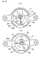
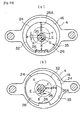
- FIGS. 12A, 12B , 13A, and 13B illustrate the relative positional relationship of the movable member 4 positioned in the region W in which penetration is impossible (shown in FIG. 10 ) and the screw 24.
- the fixed members are omitted and the cross section of the blade 26 of the screw 24 is denoted by the reference symbol 26A.
- FIG. 13A corresponds to the cross section taken along the V-V line in FIG. 10
- these figures also illustrate how the movable member 4 performs a circular movement in which the center axis line Y of the through hole 16 of the movable member 4 describes a circle with a radius equal to the eccentricity (delta) around the center axis line X of the screw 24 in the order shown in FIGS. 12A, 12B , 13A, and 13B .
- the movable member 4 does not penetrate closer to the center axis line X of the screw 24 than the outer circumferential edge 32 of the blade 26 of the screw 24 and, therefore, the movable member 4 does not interfere with the blade 26 when the movable member 4 present in the region W in which penetration is impossible occupies any position with respect to the screw 24.
- the through hole 16 of the movable member 4 that performs a circular movement is formed to fulfill the condition K > S + (delta).
- the movable member 4 that can perform a circular movement, while penetrating closer to the center axis line X of the screw than the outer circumferential edge 32 of the blade 26 of the screw 24, should be positioned within the region Z in which penetration is possible (shown in FIG. 10 ); this region Z in which penetration is possible is determined in the following manner.
- a straight line passing through the outer circumferential edge crossing point J and extending parallel to the center axis line X of the screw 24 is taken as a center parallel line L and crossing points of the center parallel line L with two blade portions 33 of the screw 24 that are adjacent in the direction of the center axis line X of the screw 24 are taken as blade crossing points M
- a region of a predetermined width in the direction of the center axis line X of the screw 24 that is narrower than the distance between the aforementioned two blade portions 33 and includes a center point N of the two blade crossing points M will be the aforementioned region Z in which penetration is possible.
- the region Z in which penetration is possible is narrower than the distance between the two adjacent blade portions 33, that is, narrower than a pitch P.
- the aforementioned movable member 4 that performs a circular movement, while penetrating closer to the center axis line X of the screw 24 than the outer circumferential edge 32 of the blade 26 of the screw 24, is positioned within the region of this width, that is, within the region Z in which penetration is possible.
- This condition is taken as the second conditions for penetration of the movable member. Where the aforementioned first and second conditions are fulfilled, the movable member 4 can perform a circular movement, while penetrating closer to the center axis line X of the screw 24 than the outer circumferential edge 32 of the blade 26 of the screw 24.
- FIG. 15 illustrates an example in which the width of the region Z in which penetration is possible is decreased with respect to that in the case shown in FIG. 10 .
- the center axis line of the through hole 16 of the movable member 4 and the center axis line of the eccentric cams 57, 157 coincide, and the movable member 4 performs a circular movement, while the center axis line Y of the through hole 16 of the movable member 4 describes a circle around the center axis line X of the screw 24.
- the shortest distance K becomes the shortest distance from the center axis line of the through hole 16 of the movable member 4 to the circumferential edge 35 of the movable member 4 demarcating the through hole 16.
- this shortest distance K is defined as the shortest distance from the center axis line of the eccentric cams 57, 157 to the circumferential edge 35 of the movable member 4 demarcating the through hole 16 of the movable member 4.
- FIGS. 17A, 17B , 18A, and 18B are explanatory drawings illustrating the above-described feature and showing a state of the region in which penetration is possible in the case in which the center axis line of the through hole 16 of the movable member and the center axis line Y of the eccentric cams 57, 157 formed with a round outer circumferential surface do not coincide.
- the through hole 16 of the movable member is shown by a two-dot-dash line
- the eccentric cams 57, 157 are shown by a dot-dash line
- the screw 24 is shown by a solid line
- the cross section of the blade 26 of the screw 24 is denoted by the reference symbol 26A.
- the eccentric cams 57, 157 fixed to the shaft 25 of the screw 24 rotate in the order shown in FIGS. 17A, 17B , 18A, and 18B , while, as shown by arrow E, the center axis line Y of the eccentric cams describes a circle with a radius equal to the eccentricity (delta) of the eccentric cams 57, 157 around the center axis line X of the screw 24.
- a portion of the movable member that is obliquely hatched in FIGS. 17 and 18 penetrates closer to the center axis line X of the screw 24 than the outer circumferential edge 32 of the blade 26 of the screw 24.
- the center axis line of the through hole 16 does not coincide with the center axis line Y of the eccentric cams 57, 157 and in this aspect the aforementioned configuration is different from that of the example shown in FIGS. 8 , 9 , and 11 .
- condition of S - (delta) ⁇ K should be fulfilled in order to prevent the portion 52 of the movable member from interfering with the blade portion 34, as shown in FIG. 18A .
- the through hole 16 of the movable member that performs a circular movement, while penetrating closer to the center axis line X of the screw 24 than the outer circumferential edge 32 of the blade 26 of the screw 24, is also formed such that the condition of S - (delta) ⁇ K ⁇ S + (delta), which is the first condition for penetration the movable members, is fulfilled.
- FIGS. 8 , 9 , and 11 illustrate a special case of the example shown in FIGS. 17 and 18 .
- FIGS. 19A, 19B , 20A, and 20B are explanatory drawings similar to FIGS. 17 and 18 that show the state of the region in which penetration is impossible in the case in which the center axis line of the through hole 16 of the movable member does not match the center axis line Y of the eccentric cams 57, 157.
- the screw 24 rotates in the order shown in FIGS. 19A, 19B , 20A, and 20B , and the eccentric cams 57, 157 rotate, while, as shown by arrow E, the center axis line Y thereof describes a circle with a radius equal to the eccentricity (delta) of the center axis line Y around the center axis line X of the screw 24.
- the movable member having the through hole 16 performs a circular movement.
- FIGS. 12 and 13 illustrate a special case of the example shown in FIGS. 19 and 20 , that is, the case in which the center axis line of the through hole 16 and the center axis line of the eccentric cams 57, 157 coincide.
- the region Z in which penetration is possible can be determined in the same manner as explained hereinabove in relation to FIG. 10 , including the case in which the center axis line of the through hole 16 and the center axis line of the eccentric cams 57, 157 do not coincide.
- the movable member 4 that performs a circular movement, while penetrating closer to the center axis line X of the screw 24 than the outer circumferential edge 32 of the blade 26 of the screw 24, is positioned within the region Z in which penetration is possible and which has a predetermined width in the direction of the center axis line X of the screw and is narrower than the distance between the aforementioned two blade portions 33 and includes a center point N of the two blade crossing points M, regardless of whether or not the center axis line of the through hole 16 and the center axis line of the eccentric cams 57, 157 coincide.
- the through hole 16 of the movable member 4 has a round form, but as mentioned hereinabove, the through hole 16 can have an appropriate shape other than the round shape, for example, an oval or polygonal shape.
- the oval shape as referred to herein includes not only an elliptical shape, but also a shape obtained by collapsing a circle.
- the aforementioned first and second conditions for penetration of the movable members may be fulfilled in order to enable the movable members to perform a circular movement, while penetrating closer to the center axis line of the screw than the outer circumferential edge of the blade of the screw, without coming into contact with the screw.
- a condition will be explained that relates to the case in which the center axis line of the through holes and the center axis line of the eccentric cams 57, 157 coincide and the through holes are ovals. Since the second condition for penetration of the movable members is absolutely identical to that described hereinabove, redundant explanation thereof is herein omitted, and the first condition for penetration of the movable members will be explained.
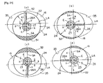
- FIGS. 21A to 21D are explanatory drawings that are similar to FIGS. 8 and 9 and illustrate the relative positional relationship of the through hole 16 of the movable member positioned in the region in which penetration is possible and the screw 24.
- the through hole 16 is shown by a two-dot-like line and the screw 24 is shown by a solid line to facilitate the understanding of the drawings.
- the reference symbol 26A in these drawings also denotes the cross section of the blade 26 of the screw 24. Since the through hole 16 of the movable member shown herein has an oval shape, the center axis line Y thereof is a crossing point of the long axis LA and short axis SA of the oval.
- the movable member performs a circular movement in the order presented in FIGS. 21A to 21D , as shown by arrow E, while the center axis line Y of the through hole 16 describes a circle with a radius equal to the eccentricity (delta) of the center axis line Y of the through hole 16 with respect to the center axis line X of the screw 24.
- the obliquely hatched portion of the movable member in FIG. 21 also penetrates closer to the center axis line X of the screw 24 than the outer circumferential edge 32 of the blade 26 of the screw 24.
- the shortest distance from the center axis line Y of the through hole 16 of the movable member to the circumferential edge 35 of the movable member that demarcates the through hole 16 is denoted by K
- the radius of the screw 24 is denoted by S
- the eccentricity of the center axis line Y of the through hole 16 with respect to the center axis line X of the screw 24 is denoted by (delta). Since the through hole 16 shown herein is an oval, the shortest distance K from the center axis line Y thereof to the circumferential edge 35 is 1/2 of the short axis SA of the through hole 16.
- the condition of K ⁇ S + (delta) should be fulfilled in order that the portion 51 of the movable member, which is hatched obliquely, could penetrate closer to the center axis line X of the screw 24 than the outer circumferential edge 32 of the blade 26 of the screw 24. Further, the condition of K > S - (delta) should be fulfilled in order to prevent the portion 52 of the movable member from coming into contact with the blade 26 of the screw 24.
- the condition for enabling the movable member to penetrate closer to the center axis line X of the screw 24 is S - (delta) ⁇ K ⁇ S + (delta) and this condition matches the aforementioned first condition.
- the shortest distance K should be larger than the sum of the radius S and the eccentricity (delta) of the screw, that is, the condition of K > S + (delta) should be fulfilled.
- This condition matches the aforementioned interference avoidance condition. Where such condition is fulfilled, even when the movable member present in the region in which penetration is impossible occupies any position with respect to the screw 24, this movable member can perform a circular movement without interfering with the screw 24.
- Other features and operations of the solid-liquid separator shown in FIG. 21 are similar to those of the solid-liquid separator explained hereinabove with reference to FIGS. 1 to 15 .
- the region Z in which penetration is possible, region W in which penetration is impossible, first and second conditions for penetration, and interference avoidance condition can be determined in exactly the same manner as described above, and the movable member having the through hole of such shape can be used without any obstacle.
- FIG. 22A when the through hole 16 of the movable member has a quadrangular shape, the length of one side is (a), and the length of the other side is (b), the crossing point of the lines equal to 1/2 of each side is the center axis line Y thereof.
- the center axis line Y thereof is the position of the center of gravity of the triangle.
- the through hole of the movable member have a round or oval shape than the polygonal shape. Further, a large number of zigzag protrusions and depressions can be also formed at the circumferential edge 35 demarcating the round, oval, or polygonal through holes 16 of the movable members 4.
- FIGS. 23A, 23B , 24A, and 24B similarly to FIGS. 8A, 8B , 9A and 9B , are cross-sectional views illustrating another example serving to clarify the circular movement of the movable member 4 positioned in the region in which penetration is possible.
- FIGS. 23 and 24 the depiction of fixed members is omitted in the same manner as in FIG. 11 .
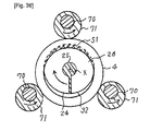
- the through hole 16 of the movable member 4 shown herein has a round basic shape centered on the center axis line Y, a protruding section 36 is formed in the circumferential edge 35 of the movable member 4 demarcating the through hole 16, and the through hole is configured such that the protruding section 36 penetrates closer to the center axis line X of the screw 24 than the outer circumferential portion 32 of the blade 26 of the screw 24.
- the movable member 4 that performs a circular movement, while penetrating closer to the center axis line X of the screw 24 than the outer circumferential portion 32 of the blade 26 of the screw 24 is configured such that part of the circumferential edge 35 of the movable member 4 demarcating the through hole 16 of the movable member 4 protrudes closer to the center axis line Y of the through hole 16 than other circumferential edge portions, and this protruding section 36 penetrates closer to the center axis line X of the screw 24 than the outer circumferential portion 32 of the blade 26 of the screw 24.
- the reference symbol 26A also denotes the cross section of the blade 26 integrated with the shaft 25 of the screw 24.
- the center axis line Y of the through hole 16 is also offset by (delta) with respect to the center axis line X of the screw 24, and the movable member 4 performs a circular movement in the order shown in FIGS. 23A , 24B, 24A, and 24B , while the center axis line Y of the through hole 16 thereof describes a circle having a radius equal to the eccentricity (delta) around the center axis line X of the screw 24, as shown by arrow E.
- the first and second conditions for penetration of the movable members may be also fulfilled to enable the movable member 4 to perform a circular movement, without coming into contact with the screw 24, while the protruding section 36 of the movable member 4 penetrates closer to the center axis line X thereof than the outer circumferential edge 32 of the blade 26 of the screw 24. Since the second condition is obtained in exactly the same manner as explained hereinabove, only the first condition for penetration of the movable members 4 will be clarified below.
- oblique hatching is also provided with respect to a portion in which the protruding section 36 of the movable member 4 penetrates closer to the center axis line X of the screw 24 than the outer circumferential edge 32 of the blade 26 of the screw 24.
- this shortest distance K will be the distance from the center axis line Y of the through hole 16 to the protruding section 36.
- the movable member 4 can perform a circular movement, while penetrating closer to the center axis line X of the screw 24 than the outer circumferential edge 32 of the blade 26 thereof, without interfering with the screw 24.
- the condition of K > S + (delta) should be also fulfilled, as follows from FIG. 24A , in order to prevent the movable member positioned in the region in which penetration is impossible from interfering with the screw 24. Where such condition is fulfilled, the movable member present in the region in which penetration is impossible can perform a circular movement without coming into contact with the screw 24.
- Other features of the solid-liquid separator shown in FIGS. 23 and 24 are similar to those of the abovementioned solid-liquid separator shown in FIGS. 1 to 20 .
- the solid-liquid separator explained hereinabove with reference to FIGS. 21 , 23 , and 24 is configured such that the center axis line of the through hole 16 of the movable member and the center axis line of the eccentric cams 57, 157 (see FIGS. 8 and 9 ) coincide and the movable member performs a circular movement such that the center axis line Y thereof describes a circle with a radius equal to the eccentricity (delta) of the eccentric cams 57, 157 around the center axis line X of the screw 24.
- the explanation provided hereinabove clearly demonstrates that where the shortest distance from the center axis line of the eccentric cams 57, 157 to the circumferential edge 35 of the movable member demarcating the through hole 16 of the movable member is denoted by K and the configuration is used in which the condition of S - (delta) ⁇ K ⁇ S + (delta) is fulfilled and the condition of K > S + (delta) is fulfilled, the movable member penetrates closer to the center axis line X than the outer circumferential edge 32 of the screw 24, without interfering with the screw 24, even when the center axis lines of the movable members do not coincide, or the center axis line of the through hole 16 and the center axis line of the eccentric cams 57, 157 do not coincide, or the center axis line of the through hole 16 is not defined.
- the solid-liquid separator in which the center axis lines Y of the through holes 16 of all of the movable members 4 coincide and the movable members perform a circular movement, while the center axis lines Y thereof describe a circle with a radius equal to the eccentricity (delta) of the center axis line Y of the through hole 16 of the movable member 4 around the center axis line X of the screw 24, but as mentioned hereinabove a configuration in which the center axis lines of the movable members 4 do not coincide can be also used. Furthermore, in another possible configuration, as shown schematically by a broken line and a two-dot-dash line in FIG.
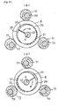
- FIG. 25A shows movable members of two types, namely, a movable member provided with the through hole 16 having the center axis line Y and a movable member provided with the through hole 16A having the center axis line YA that does not coincide with the center axis line Y, but movable members of three or more types in which the center axis lines do not coincide can be also provided.
- FIG. 25A shows movable members of two types, namely, a movable member provided with the through hole 16 having the center axis line Y and a movable member provided with the through hole 16A having the center axis line YA that does not coincide with the center axis line Y, but movable members of three or more types in which the center axis lines do not coincide can be also provided.
- FIG. 25A shows movable members of two types, namely, a movable member provided with the through hole 16 having the center axis line Y and a movable member provided with the through hole 16
- 25B illustrates a solid-liquid separator including a first plurality of movable members provided with through holes 16 having a center axis line Y, a second plurality of movable members provided with through holes 16A having a center axis line YA, and a third plurality of movable members provided with through holes 16B having a center axis line YB.
- the center axis lines Y, YA, YB are decentered from the center axis line X of the screw 24, and the center axis lines Y, YA, YB do not coincide with each other.
- the movable members of three types perform circular movements, while the center axis lines Y, YA, YB thereof describe circles with radiuses equal to the eccentricities of the center axis lines Y, YA, YB of the through holes 16, 16A, 16B of the movable members around the center axis line X of the screw 24.
- the solid-liquid separator can be configured to have a plurality of eccentric cams with center axis lines Y, YA, YB that do not coincide.
- the center axis lines Y, YA, YB of the plurality of eccentric cams are decentered from the center axis line X of the screw 24, and the plurality of eccentric cams rotate, while the center axis lines Y, YA, YB thereof describe circles with radii equal to the eccentricities of the eccentric cams around the center axis line X of the screw 24.
- Such a configuration can be used regardless of whether or not the center axis line of the movable member and the center axis line of the eccentric cams coincide.
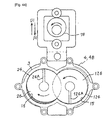
- FIG. 26 is a perspective view of a solid-liquid separator in which the configuration shown in FIG. 25A is realized.
- the outlet member 2 shown in FIG. 1 is simplified and some elements such as the electric motor 28 shown in FIG. 1 is omitted.
- FIG. 31 illustrates the mutual arrangement of the movable members and the screw 24 in this solid-liquid separator. This figure is an explanatory cross-sectional view similar to that of FIG. 10 , and the depiction of fixed members herein is omitted.
- FIG. 27 is a view corresponding to the cross section taken along the VI-VI line in FIG. 31 .
- FIG. 28 is a view corresponding to the cross section taken along the VII-VII line in FIG. 31 .
- FIG. 29 is an enlarged cross-sectional view corresponding to the cross section taken along the VIII-VIII line in FIG. 26 .
- FIG. 30 is an enlarged sectional view taken along the IX-IX line in FIG. 26 .
- the solid-liquid separator of the present embodiment also has a plurality of fixed members 3, and the adjacent fixed members 3 are arranged at a distance from each other that is determined by spacers 14 disposed therebetween, as shown in FIGS. 26 to 28 .
- the plurality of fixed members 3 are fixed to each other by four stay bolts 18 extending through the fixed members 3 and the spacers 14, and movable members 4, 4A are disposed between the adjacent fixed members 3.
- the round through hole 15 is formed in the fixed member 3, the round through holes 16, 16A are formed in the movable members 4, 4A, and the solid-liquid separation portion 21 is demarcated by the through holes 15, 16, 16A.
- a single screw 24 having one blade 26 extends through the through holes 15, 16, 16A of the fixed members 3 and the movable members 4, 4A, without coming into contact with the fixed members 3 and movable members 4, 4A.
- Sludge is pumped in from the inflow port 5 of the inlet member 1 shown in FIG. 26 and flows into the solid-liquid separation portion 21 shown in FIGS. 27 and 28 .
- the screw 24 is rotationally driven about the center axis line X thereof by an electric motor (not shown in FIG. 26 ).
- the sludge is conveyed toward the outlet 23 of the solid-liquid separation portion 21, the filtrate is discharged to the outside of the solid-liquid separation portion 21 through a filtrate discharge gaps between the fixed members 3 and the movable members 4, 4A, and the sludge with a reduced content ratio of water is discharged to the outside of the solid-liquid separation portion form the outlet 23.
- the screw 24 of the solid-liquid separator of the present embodiment has the blade 26 and the shaft 25 that is formed integrally with the blade 26 and constitutes the center portion of the screw.
- the basic configuration and operation of the solid-liquid separator of the present embodiment are not different from those of the solid-liquid separator explained hereinabove.
- the solid-liquid separator of the present embodiment has a plurality of movable members 4 and also a plurality of movable members 4A shown in FIGS. 26 to 31 , but if necessary the former movable member 4 can be referred to as “some movable members” and the latter movable members 4A can be referred to as “other movable members”. As follows from FIGS.
- the center axial lines Y, YA of the round through holes 16, 16A of these movable members 4, 4A are both offset by (delta) with respect to the center axis line X of the shaft 25 of the screw 24, but all of the center axial lines Y of the through holes 16 of some movable members 4 coincide with each other, and all of the center axial lines YA of the through holes 16A of the other movable members 4A coincide with each other. However, the center axial lines Y of the through holes 16 of some movable members 4 do not coincide with the center axial lines YA of the through holes 16A of the other movable members 4A.
- the eccentric cams 57, 157 with round outer circumferential surfaces 58, 158 are detachably attached at end portions, in the longitudinal direction, of the shaft 25 of the screw 24, and the round outer circumferential surfaces 58, 158 of the eccentric cams 57, 157 are mated with the round cam holes 60, 160 of the bearings 59, 159 constituted by sliding bearings.
- the center axis line Y of the eccentric cams 57, 157 is offset by (delta) with respect to the center axis line X of the shaft 25 of the screw 24, and the round outer circumferential surfaces 58, 158 of the eccentric cams 57, 157 slidably abut, directly or with a lubricant located therebetween, on the inner circumferential surfaces of the round cam holes 60, 160 of the bearings 59, 159.
- the center axis lines Y of the two eccentric cams 57, 157 coincide.
- the bearings 59, 159 mate with the attachment holes 62, 162 of the connection plates 61, 161 and are detachably attached and connected to the connection plates 61, 161.
- connection plates 61, 161 are detachably attached by nuts 67, 167 to the connection plates 61, 161, and the two connection plates 61, 161 are fixedly connected by the two connecting rods 66.
- the two connecting rods 66 extend through the attachment holes 65 (see also FIGS. 27 and 28 ) formed in the part of the plurality of movable members 4.
- a pair of connection plates 61, 161 and the connecting rods 66 also constitute a connection means for connecting the part of the plurality of movable members 4.
- the eccentric cams 57, 157 provided in the solid-liquid separator of the present embodiment and the aforementioned elements associated therewith are not substantially different from the eccentric cams 157, 157 of the solid-liquid separator shown in FIGS. 1 to 15 and the elements associated therewith.
- a second eccentric cam and elements associated therewith are provided, as explained hereinabove, in addition to the aforementioned eccentric cams 57, 157. Therefore, the aforementioned eccentric cams 57, 157, bearings 59, 159, connection means, and connection plates 61, 161 and connecting rods 66 constituting the connection means will be referred to as the first eccentric cams 57, 157, first bearings 59, 159, first connection means, and first connection plates 61, 161, and first connecting rods 66, respectively.
- second eccentric cams 57A, 157A are detachably attached to the end portions, in the longitudinal direction, of the shaft 25 of the screw 24, and these second eccentric cams 57A, 157A also have round external circumferential surfaces 58A, 158A formed therein. Furthermore, the center axial lines YA of the second eccentric cams 57A, 157A coincide, and the center axis line YA is offset by (delta) with respect to the center axis line X of the screw 24.
- center axis line YA of the round through hole 16A of the other movable members 4A coincides with the center axis line YA of the second eccentric cams 57A, 157A.
- the center axis line Y of the first eccentric cams 57, 157 does not coincide with the center axis line YA of the second eccentric cams 57A, 157A.
- the round external circumferential surfaces 58A, 158A of the second eccentric cams 57A, 157A are also mated with the round cam holes 60A, 160A of the second bearings 59A, 159A constituted by sliding bearings, and the round outer circumferential surfaces 58A, 158A of the second eccentric cams 57A, 157A slidably abut along the entire circumference thereof, directly or with a lubricant located therebetween, on the inner circumferential surfaces of the round cam holes 60A, 160A of the second bearings 59, 159A.
- the second bearings 59, 159A are mated with the attachment holes 62A, 162A of the second connection plates 61A, 161A and detachably attached and connected to the respective second connection plates 61A, 161A.
- Two connecting rods 66A are fixed by nuts 67A, 167A shown in FIG. 26 to the respective second connection plates 61A, 161A, and the second connection plates 61A, 161A are fixedly connected by the two second connecting rods 66A.
- the two second connecting rods 66A extend through the attachment holes 65A formed in the other part of the plurality of movable members 4A.
- a pair of second connection plates 61A, 161A and second connecting rods 66A constitute second connection means connecting the other part of the plurality of movable members 4A.
- first eccentric cams 57, 157 and second eccentric cams 57A, 157A are additionally shown by two-dot-dash lines.
- the center axis line Y of the first eccentric cams 57, 157 and the center axis line YA of the second eccentric cams 57A, 157A do not coincide
- the center axis line Y of the through holes 16 of the part of the plurality of movable members 4 and the center axis line Y of the first eccentric cams 57, 157 coincide
- the center axis line YA of the through holes 16A of the other part of the plurality of movable members 4A and the center axis line YA of the second eccentric cams 57A, 157A coincide. Therefore, the center axis line Y of the through holes 16 of the part of the plurality of movable members 4 and the center axis line YA of the through holes 16A of the other part of the plurality of movable members 4A do not coincide.
- the second eccentric cams 57A, 157A also rotate, while the center axis line YA thereof describes a circle with a radius equal to the eccentricity (delta) around the center axis line X of the shaft 25 of the screw 24, as shown by arrow EA.
- the other part of the plurality of movable members 4A follow this rotation and perform a circular movement, while the center axis line YA thereof describes a circle around the center axis line X of the screw 24.
- the center axis lines Y and YA do not coincide, the part of the plurality of movable members 4 and other part of the plurality of movable members 4A perform circular movements with different phases.
- the movable members perform circular movements with a phase difference of 180 degree.
- the circular movements of the movable members 4, 4A prevent solid mater from clogging the space between the movable members and the fixed members 3.
- the solid-liquid separator shown in FIGS. 26 to 30 includes the first connection means for connecting the part of the plurality of movable members 4 so that the part of the plurality of movable members 4 can perform together a circular movement, the first eccentric cams 57, 157 that are decentered from the center axis line X of the shaft 25 of the screw 24 and rotate integrally with the shaft 25, the first bearings 59, 159 that are connected to the first connection means and provided with round cam holes 60, 160 that mate with the round outer circumferential surfaces 58, 158 of the first eccentric cams 57,157, the second connection means for connecting the other part of the plurality of movable members 4A so that the other part of the plurality of movable members 4A can perform together a circular movement, the second eccentric cams 57A, 157A that are decentered from the center axis line X of the shaft 25 of the screw 24 and rotate integrally with the shaft 25, and the second bearings 59A, 159A that are connected to
- the first eccentric cams 57, 157 and the first bearings 59, 159 mated with the first eccentric cams 57, 157 are provided by one each at each of the portions of the shaft 25 that are outside, in the longitudinal direction, of the blade 26 of the screw 24,
- the first connection means has a pair of first connection plates 61, 161 connected to respective first bearings 59, 159 and a plurality of first connecting rods 66 connected to the part of the plurality of movable members 4, each first connecting rod 66 is connected to the respective first connection plate 61, 161
- the second eccentric cams 57A, 157A and the second bearings 59A, 159A mated with the second eccentric cams 57A, 157A are provided by one each at each of the portions of the shaft 25 that are outside, in the longitudinal direction, of the blade 26 of the screw 24,
- the second connection means has a pair of second connection plates 61A, 161A connected to respective second bearings 59
- the ring-shaped guides 69, 69A are detachably attached by bolts and nuts (not shown in the figure) to the holes in the side plates 7, 9 of the inlet member 1 and the outlet member 2 through which the first and second connecting rods 66, 66A pass.
- first and second connecting rods 66, 66A When the first and second connecting rods 66, 66A perform a circular movement, the first and second connecting rods 66, 66A are guided, while sliding along the inner circumferential surfaces of the ring-shaped first and second guides 69, 69A, and the first and second connecting rods 66, 66A are prevented from rotating about the center axis line X of the screw 24 (see arrow F in FIG. 8A ).
- the solid-liquid separator of the present embodiment has the first guide 69 that prevents the first connection means from rotating together with the part of the plurality of movable members 4 connected by the first connection means around the center axis line X of the shaft 25 of the screw 24 and the movable members 4 from coming into contact with other members, and the second guide 69A that prevents the second connection means from rotating together with the other part of the plurality of movable members 4A connected by the second connection means around the center axis line X of the shaft 25 of the screw 24 and the movable members 4A from coming into contact with other members.
- Described hereinabove with reference to FIGS. 25 to 30 is an example in which the configuration having the first eccentric cams 57, 157 and the second eccentric cams 57A, 157A is applied to the solid-liquid separator in which the center axis line of the first eccentric cams 57, 157 and the center axis line of the through holes 16 formed in the part of the plurality of movable members 4 coincide and the center axis line of the second eccentric cams 57A, 157A and the center axis line of the through holes 16A formed in the other part of the plurality of movable members 4A coincide.
- the configuration having a plurality of eccentric cams can be also applied to the solid-liquid separator in which the center axis line of the first eccentric cams 57, 157 and the center axis line of the through holes 16 formed in the part of the plurality of movable members 4 do not coincide and the center axis line of the second eccentric cams 57A, 157A and the center axis line of the through holes 16A formed in the other part of the plurality of movable members 4A do not coincide, and also to the solid-liquid separator in which the center axis lines of the part of the plurality of movable members 4 do not coincide with each other and the center axis lines of the other part of the plurality of movable members 4A do not coincide with each other.
- the basic configuration is not different from that shown in FIGS. 25 to 30 .
- the first eccentric cams 57, 157 that are decentered from the center axis line X of the shaft 25 of the screw 24 and have a round outer circumferential surface and the second eccentric cams 57A, 157A that are also decentered from the center axis line X of the shaft 25 of the screw 24 and have a round outer circumferential surface are fixed to the shaft 25 of the screw 24, the center axis line of the first eccentric cams 57, 157 and the center axis line of the second eccentric cams 57A, 157A do not coincide, the part of the plurality of movable members 4 are connected to the first eccentric cams 57, 157 such that the part of the plurality of movable members 4 perform a circular movement with a radius equal to the eccentricity (delta) of the first eccentric cams 57, 157, and the other part of the plurality of movable members 4A are connected to the second eccentric cams 57
- the solid-liquid separator is provided with the first connection means that connects the part of the plurality of movable members 4 so that the part of the plurality of movable members 4 together perform a circular movement and the first bearings 59, 159 that are connected to the first connection means and provided with the round cam holes 60, 160 that mate with the round outer circumferential surfaces 58, 158 of the first eccentric cams 57, 157.
- the solid-liquid separator is also provided with the second connection means that connects the other part of the plurality of movable members 4A so that the other part of the plurality of movable members 4A together perform a circular movement and the second bearings 59A, 159A that are connected to the second connection means and provided with the round cam holes 60A, 160A that mate with the round outer circumferential surfaces 58A, 158A of the second eccentric cams 57A, 157A.
- the round outer circumferential surfaces 58, 158 of the first eccentric cams 57, 157 slidably abut on the inner circumferential surfaces of the round cam holes 60, 160 of the first bearings 59, 159 over the entire circumference thereof
- the round outer circumferential surfaces 58A, 158A of the second eccentric cams 57A, 157A slidably abut on the inner circumferential surfaces of the round cam holes 60A, 160A of the second bearings 59A, 159A over the entire circumference thereof.
- the first eccentric cams 57, 157 rotate, while the center axis line thereof describes a circle with a radius equal to the eccentricity (delta) of the first eccentric cams 57, 157 around the center axis line X of the shaft 25 of the screw 24.
- the part of the plurality of movable members 4 connected by the first connection means perform a circular movement with a radius equal to the eccentricity (delta) of the first eccentric cams 57, 157.
- the second eccentric cams 57A, 157A rotate, while the center axis line thereof describes a circle with a radius equal to the eccentricity (delta) of the second eccentric cams 57, 157A around the center axis line X of the shaft 25 of the screw 24.
- the other part of the plurality of movable members 4 connected by the second connection means perform a circular movement with a radius equal to the eccentricity (delta) of the second eccentric cams 57A, 157A.
- the part of the plurality of movable members 4 and the other part of the plurality of movable members 4A of the above-described embodiments are also configured such that at least part of the movable members perform a circular movement, while penetrating closer to the center axis line X of the screw 24 than the outer circumferential edge 32 of the blade 26 of the screw 24, without coming into contact with the screw 24.
- the aforementioned first condition and second condition for penetration of the movable members should be fulfilled in order that the movable members 4, 4A could penetrate closer to the center axis line X of the screw 24 than the outer circumferential edge 32 of the blade 26 of the screw 24.
- FIG. 31 is a cross sectional explanatory drawing that is similar to FIG. 10 and illustrates an example of the relationship between the movable members 4, 4A and the screw 24 in the solid-liquid separators of the above-described embodiments.
- the depiction of the fixed members is omitted and the arrangement state of the movable members 4, 4A and the screw 24 does not coincide with that shown in FIG. 26 .
- five of the some movable members 4 and five of the other movable members 4A are arranged alternately in the direction of the center axis line X of the screw 24.
- a region of a predetermined width in the direction of the center axis line X of the screw 24 that is narrower than the distance between the aforementioned two blade portions 33 and includes a center point N of the two blade crossing points M will be a region Z in which penetration of the movable members 4 is possible.
- the movable member 4 that performs a circular movement, while penetrating closer to the center axis line X of the screw 24 than the outer circumferential edge 32 of the blade 26 of the screw 24, is positioned within the region Z in which penetration is possible.
- the portions 51 of the three movable members 4 got closer to the center axis line X of the screw 24 than the outer circumferential edge 32 of the blade 26 thereof. This is the second condition under which the movable members 4 can penetrate and this conditions is not different from that explained hereinabove.
- the shortest distance K in this case, the radius of the round through hole 16
- the shortest distance K from the center axis line Y of the first eccentric cams 57, 157 or the center axis line Y of the through holes 16 of some movable members 4 to the circumferential edge 35 of the movable members 4 demarcating the through hole 16, the radius S of the screw 24, and the eccentricity (delta) of the through hole 16 should fulfill the relationship S - (delta) ⁇ K ⁇ S + (delta). This is also the first condition for enabling the penetration of the movable members 4 described hereinabove.
- the movable members 4 positioned in the region W, which is outside the above-described region Z in which penetration is possible and represents a region in which penetration is impossible, is specifically assigned with the reference numeral 54, and the through hole 16 of this movable members 54 is formed such that the condition K > S + (delta) (interference avoidance condition) is fulfilled.
- the movable members 54 can perform a circular movement, without coming into contact with the screw 24 or penetrating closer to the center axis line X than the outer circumferential edge 32.
- FIGS. 32A to 32D are explanatory drawings illustrating the relative arrangement of the through hole 16 of the movable members 4 positioned in the region Z in which penetration is possible and the screw 24, and also the circular movement of the movable members 4.
- the reference symbol 26A also denotes the cross section of the blade 26 of the screw 24.
- the portion of the movable members 4 that is shown by oblique hatching is shown to have penetrated closer to the center axis line X of the screw 24 than the circumferential outer edge 32 of the blade 26 thereof.
- a region of a predetermined width in the direction of the center axis line X of the screw 24 that is narrower than the distance between the aforementioned two blade portions 33A and includes a center point NA of the two blade crossing points MA will be a region ZA in which penetration of the movable members 4A is possible.
- the portions 51A of three movable members 4A have penetrated closer to the center axis line X of the screw 24 than the outer circumferential edge 32. This is the second condition under which the movable members 4A can penetrate.
- the shortest distance K in this case, the radius of the round through hole 16A
- the radius S of the screw 24 and the eccentricity (delta) of the through hole 16A should fulfill the relationship S - (delta) ⁇ K ⁇ S + (delta). This is the first condition for enabling the penetration of the movable members 4A.
- the movable members 4A positioned in the region WA, which is outside the above-described region ZA in which penetration is possible and represents a region in which penetration is impossible, is specifically assigned with the reference numeral 54A, and the through hole 16A of this movable members 54A is formed such that the condition K > S + (delta) (interference avoidance condition) is fulfilled.
- the movable members 54A can perform a circular movement, without coming into contact with the screw 24 and penetrating closer to the center axis line X than the outer circumferential edge 32.
- FIGS. 32E to 32H are explanatory drawings illustrating the relative arrangement of the through hole 16A of the movable members 4A positioned in the region ZA in which penetration is possible and the screw 24, and also the circular movement of the movable members 4A.
- the reference symbol 26A also denotes the cross section of the blade 26 of the screw 24.
- the portion of the movable members 4A that is shown by oblique hatching is shown to have penetrated closer to the center axis line X of the screw 24 than the circumferential outer edge 32 of the blade 26 thereof.
- FIGS. 32A to 32H portions of the movable members 4 and movable members 4A that face each other with a phase difference of 180 degree are closer to the center axis line X than the circumferential outer edge 32 of the screw 24.
- FIG. 25A is a specific example of the configuration shown in FIG. 25A , that is, the solid-liquid separator having movable members 4, 4A of two types with center axis lines Y, YA that do not coincide and also having the first and second eccentric cams with center axis lines Y, YA that do not coincide.
- a solid-liquid separator having movable members of three or more types and eccentric cams of three or more types with center axis lines Y, YA, YB that do not coincide can be also configured in the same manner as described hereinabove.
- eccentric cams of three types with center axis lines that do not coincide are used.
- a solid-liquid separator can be also configured by using eccentric cams of four or more types with center axis lines that do not coincide.
- the number of movable members penetrating closer to the center axis line X than the outer circumferential edge 32 of the screw 24 can be increased and the effect of squeezing water from the sludge can be further increased.
- FIG. 33 shows the solid-liquid separator shown in FIGS. 26 to 30 in which the regions Z, ZA in which penetration of the part of the plurality of movable members 4 and the other part of the plurality of movable members 4A is possible are enlarged.
- This solid-liquid separator is configured such that the region ZA in which penetration is possible, that is, the region in which the other part of the plurality of movable members 4A can perform a circular movement, while penetrating closer to the center axis line X of the screw 24 than the outer circumferential edge 32 of the blade 26 of the screw 24, is positioned adjacently to the region Z in which penetration is possible, that is, the region in which the part of the plurality of movable members 4 can perform a circular movement, while penetrating closer to the center axis line X of the screw 24 than the outer circumferential edge 32 of the blade 26 of the screw 24.
- All of the movable members 4, 4A located in the regions Z, ZA in which penetration is possible perform a circular movement, while penetrating closer to the center axis line X of the screw 24 than the outer circumferential edge 32 of the blade 26 of the screw 24.
- all of the movable members 4, 4A perform a circular movement, while penetrating closer to the center axis line X of the screw than the outer circumferential edge 32 of the blade 26 of the screw 24, the effect of squeezing water out of the sludge can be increased to a maximum limit.
- the through holes 16, 16A of the movable members 4, 4A can be also formed to have an oval shape or a polygonal shape, and the movable members 4, 4A having protruding sections similar to the protruding section 36 shown in FIGS. 23 and 24 can be also used. Further, a large number of zigzag protrusions and depressions can be also formed at the circumferential edge 35 demarcating the through holes 16, 16A.
- the movable members 4, 4A that are present in the regions Z, ZA in which penetration is possible in the above-described solid-liquid separators can be configured, if necessary, such as not to penetrate closer to the center axis line X than the outer circumferential edge 32 of the blade 26 of the screw 24 outside a certain range.
- a configuration can be used in which only the movable members in a certain desired range penetrate closer to the center axis line X than the outer circumferential edge 32 of the blade 26 of the screw 24.
- the movable member that moves, while penetrating closer to the center axis line X of the screw 24 than the outer circumferential edge 32 of the blade 26 of the screw 24, is positioned in a region R2 downstream, in the movement direction of the treatment object, of the position corresponding to 1/2 the length R ( FIG. 1 ) of the solid-liquid separation portion 21 in the movement direction of the treatment object.
- the sludge passing through the solid-liquid separation portion in the region R1 upstream of the 1/2 length usually includes a large amount of water, and even if the movable members 4, 4A apply a shear force to the sludge, while penetrating so as to cut into the sludge, the effect of squeezing out the water cannot be sufficiently increased.
- the present invention is applied to a solid-liquid separator in which eccentric cams connected to the end portions of the shaft 25 of the screw 24 are connected to the movable members and the movable members are caused to perform a circular movement by rotationally driving the screw 24.
- the present invention can be also broadly applied to solid-liquid separators in which movable members disposed between the adjacent fixed members are moved by another appropriate means.
- JP-S59-218298-A discloses a solid-liquid separator including a plurality of fixed members, movable members disposed between the adjacent fixed members, and a screw extending via the through holes formed in the movable members and fixed members, without coming into contact with the through holes.
- the plurality of movable members are fixed by fixing rods, eccentric cams are inserted in a pair of round cam holes formed on the left and right sides, so as to sandwich the screw, of the movable members positioned at both ends in the axial direction, and the movable members are caused to perform a circular movement by rotationally driving the pair of eccentric cams.
- the present invention can be also applied to the solid-liquid separator shown in FIGS. 34 and 35 .
- the solid-liquid separator shown in these figures also includes a plurality of fixed members 3 disposed with a small clearance therebetween formed by spacers 14, movable members 4 disposed between the adjacent fixed members 3, and a screw 24 extending through the through holes 15, 16 formed in the fixed members 3 and the movable members 4.
- the through holes 15, 16 are formed such as to avoid contact with the screw 24.
- a large number of fixed members 3 are fixed to the inlet member 1 and the outlet member 2 by a plurality of stay bolts 18 and nuts, the end portion of the screw 24 on the side of the inlet member 1 is rotatably supported by a bearing on the inlet member 1, the end portion of the screw 24 on the side of the outlet member 2 is drivably connected to the electric motor 28 ( FIG. 34 ), and the electric motor 28 is fixedly supported on a gear box 74 fixed to the inlet member 2.
- hatching representing the cross section of the fixed member 37 is omitted and the cross section of the movable member 4 is painted black to facilitate the understanding of the drawing.
- FIGS. 36 , 37A, and 37B are explanatory cross-sectional views illustrating how the movable member 4 performs a circular movement following the rotation of the screw 24 shown in FIGS. 34 and 35 .
- the movable member 4 is formed to have a round outer circumference, and three eccentric cams 71 fixed to support shafts 70 abut on this round outer circumferential surface.
- the end portions, in the longitudinal direction, of the support shafts 70 are rotationally supported by bearings on the inlet member 1 and the gear box 74.
- angular positions of the eccentric cams 71 in the circumferential direction differ from each other, and the phases of the eccentric cams 71 differ from each other.
- a drive gear 72 is fixed to the shaft 25 of the screw 24 and this drive gear 72 is meshed with a driven gear 73 fixed with the support shaft 70 of the eccentric cams 71.
- the screw 24 is rotationally driven around the center axis line X thereof, this rotation is transmitted by the drive gear 72 and the driven gear 73 to the support shaft 70 of the eccentric cams 71, and the eccentric cams 71 rotate in the direction shown by the arrow in FIGS. 36 and 37 .
- the phases of the eccentric cams 71 differ from each other as described hereinabove, when the eccentric cams 71 rotate in the direction shown by the arrow, the movable members 4 perform a circular movement and also rotate (revolve) around their own center axis line.
- Sludge (not shown in the figure) is supplied from the inflow port 5 of the inlet member 1, as shown by arrow A in FIG. 35 , flows into the solid-liquid separation portion 21 demarcated by the through holes 15, 16 of the fixed members 3 and the movable members 4, and is conveyed by the rotating screw 24 in the direction shown by arrow C.
- the filtrate flows down through filtrate discharge gaps between the fixed members 3 and the movable members 4, and the sludge with a reduced water content is discharged from the solid-liquid separation portion 21 to the outlet member 2 and falls down from the discharge port 11 of the outlet member 2.
- the movable member 4 present in the region Z in which penetration is possible ( FIG. 35 ) and which has been explained in the preceding embodiments performs a circular movement, while penetrating closer to the center axis line X of the screw 24 than the outer circumferential edge 32 of the screw 24.
- the portion 51 of the movable member that has thus penetrated into the blade 26 of the screw 24 is represented by oblique hatching.
- the movable member 4 present in the region in which penetration is impossible and which is represented by the reference symbol W in FIG. 35 does not penetrate closer to the center axis line X of the screw 24 than the outer circumferential edge 32 of the screw 24. Solid-liquid separation of the sludge can thus be conducted with good efficiency.
- FIG. 38 is a perspective view illustrating yet another solid-liquid separator.
- FIG. 39 is a perspective view, as viewed from the opposite side in the axial direction, of the solid-liquid separator shown in FIG. 38 .
- FIG. 40 is a vertical sectional view of the solid-liquid separator shown in FIG. 38 . Hatching that represents cross sections is removed to simplify the drawings.
- the solid-liquid separator shown in these figures also includes a plurality of fixed members 3 disposed with a small clearance therebetween formed by spacers 14, movable members 4 disposed between the adjacent fixed members 3, and a screw 24 extending through the through holes 15, 16 formed in the fixed members 3 and the movable members 4.
- the through holes 15, 16 are formed such that the fixed members 3 and the movable members 4 do not come into contact with the screw 24. Further, a large number of fixed members 3 are fixed to the inlet member 1 and the outlet member 2 by a plurality of stay bolts 18 and nuts, the end portion of the shaft 25 of the screw 24 on the side of the inlet member 1 is rotatably supported by a bearing on the inlet member 1, the end portion of the shaft 25 of the screw 24 on the side of the outlet member 2 is drivably connected to an electric motor 28, and the electric motor 28 is fixedly supported on a gear box 74 fixed to the inlet member 2.
- FIG. 41 is an enlarged transverse sectional view of the solid-liquid separator shown in FIG. 40 .
- FIG. 42 is a cross-sectional view similar to that shown in FIG. 41 and shows the state attained after the screw 24 has further rotated from the state shown in FIG. 41 .
- the outer circumferential edge 32 of the blade 26 of the screw 24 is shown by a two-dot-dash line (same in FIGS. 43 to 48 ).
- the reference symbol 26A in FIGS. 41 and 42 denotes the cross section of the blade 26 of the screw 24.
- FIGS. 38 to 40 some movable members of a large number of movable members 4 (three movable members in the example shown in the figure) are assigned with a reference symbol 4B. Arms 75 are fixed to these movable members 4B by bolts and nuts (not shown in the figure). Holes 76 are formed in the arms 75. A shaft 77 passes through the holes 76. An eccentric cam 78 detachably attached to the shaft 77 is positioned in each hole 76. As shown in FIG. 40 , end portions, in the longitudinal direction, of the shaft 77 are rotatably supported by bearings on the inlet member 1 and the gear box 74. Further, FIG. 40 also shows that a drive gear 80 is fixed to the shaft 25 of the screw 24, and this drive gear 80 is meshed with a driven gear 81 fixed to the shaft 77.
- cam followers 79 constituted by rollers are rotatably supported on both sides of the shaft 77.
- end portions of a pair of support rods 82 are fixed to the inlet member 1 and the outlet member 2, a guide roller 83 is rotatably supported on each support rod 82, and these guide rollers 83 abut on the opposing surfaces of the arm 75.
- FIGS. 41 and 42 the depiction of the support rods 82 and the guide rollers 83 is omitted.
- a connecting rod 84 extends through all of the movable members 4, 4B, and all of the movable members 4, 4B are connected by the connecting rod 84.
- Sludge (not shown in the figure) is supplied from the inflow port 5 of the inlet member 1, as shown by arrow A in FIG. 40 , flows into the solid-liquid separation portion 21 demarcated by the through holes 15, 16 of the fixed members 3 and the movable members 4, and conveyed by the rotating screw 24 in the direction shown by arrow C.
- the filtrate flows down through filtrate discharge gaps between the fixed members 3 and the movable members 4, and the sludge with a reduced water content is discharged from the solid-liquid separation portion 21 to the outlet member 2 and falls down from the discharge port 11 of the outlet member 2.
- the movable member 4 present in the region Z ( FIG. 40 ) in which penetration is possible and which has been explained in the preceding embodiments performs a reciprocating movement, while penetrating closer to the center axis line X of the screw 24 than the outer circumferential edge 32 of the blade 26 of the screw 24.
- the portion 51 of the movable member that has thus penetrated into the blade 26 of the screw 24 is represented by oblique hatching.
- the movable member 4 present in the region in which penetration is impossible does not penetrate closer to the center axis line X of the screw 24 than the outer circumferential edge 32 of the blade 26 of the screw 24. Solid-liquid separation of the sludge can thus be conducted with good efficiency.
- FIG. 43 is a cross-sectional view of a solid-liquid separator in which two screws 24, 124 extend through the through holes 15 formed in the fixed members 3 and the through holes 16 formed in the movable members 4, 4B, and sludge is conveyed by the rotation of these screws 24, 124.
- the screws 24, 124 do not come into contact with the fixed members 3 or the movable members 4.
- FIG. 44 is a cross-sectional view illustrating a state attained when the screws 24, 124 have further rotated from the state shown in FIG. 43 . In FIGS. 43 and 44 , hatching representing the cross section of each member is omitted (same in FIGS. 45 to 48 ).
- FIG. 45 shows a solid-liquid separator having three screws 24, 124, 224.
- the screws 24, 124, 224 also extend via through holes formed in these members 3, 4, 4B and are rotationally driven in the direction shown by respective arrows, without coming into contact with the fixed members 3 or the movable members 4, 4B.
- FIG. 46 is a cross-sectional view illustrating the state attained after the screws 24, 124, 224 have further rotated from the state shown in FIG. 45 .
- parts of the blades 26, 126 of the screws 24, 124 are positioned in a state of overlapping, when the screws 24, 124 shown in FIGS. 43 and 44 are viewed in the direction of the center axis line thereof.
- the mutually adjacent screws 24, 124 should be rotated in the mutually opposite directions as shown by arrows in FIGS. 43 and 44 in order to prevent the blades 26, 126 of these screws 24, 124 from interfering with each other.
- the movable members 4, 4B present in the region in which penetration is possible perform a reciprocating movement, while penetrating closer to the center axis line than the outer circumferential edge of the screws 24, 224.
- the movable members 4, 4B do not penetrate into the blade of the screw 124 positioned adjacently to the screws 24, 224.
- a cross-sectional portion 26A of the blade 26 of one screw 24 and the cross-sectional portion 126A of the blade 126 of the other screw 124 face in the mutually opposite directions. Therefore, when the movable members 4, 4B descend as shown in FIG. 43 , the cross-sectional portion 26A of the blade 26 faces down, and the upper portions of the movable members 4, 4B penetrate into the blade of the screw 24, the cross-sectional portion 126A of the blade 126 of the other screw 124 faces up. Therefore, the upper portions of the movable members 4, 4B do not penetrate into the blade of the other screw 124.
- the solid-liquid separator should be configured such that the movable members 4, 4B do not penetrate into the blade of the other screw.
- a large number of fixed members 103 having a recess 85 formed in the upper portions thereof are disposed with a clearance in the axial direction formed by spacers 114, movable members 104 are disposed between the adjacent fixed members 103, and recesses 86 are also formed in the upper portion of the movable member 104.
- a plurality of fixed members 103 are fixedly connected by stay bolts 118, and two screws 24, 124 extend through the recesses 85, 86 of the fixed members 103 and the movable members 104 in a state without contact with the fixed members 103 and the movable members 104.
- screws 24, 124 are also positioned in a state of partial overlapping, when viewed in the axial direction thereof. Therefore, in this case, too, the screws 24, 124 are rotationally driven in the mutually opposite directions, as shown by arrows, in order to prevent the screws from interfering with each other.
- the upper portions of the screws 24, 124 are covered with a cover 87.
- the plurality of movable members 104 shown in FIG. 47 are connected by the connecting rod 84, and an arm 175 is integrally attached to some movable members 104B from among the plurality of movable members 104.
- a cam follower 179 is rotatably supported by the arm 175.
- An eccentric cam 178 is fixed to a rotationally driven shaft 177, and when the eccentric cam 178 is rotationally driven, the cam follower 179 and the movable member 104B move reciprocatingly in the direction shown by arrows E1, F1 in FIGS. 47 and 48 . As a result, all of the movable members 104 move reciprocatingly. Solids of the sludge are thus prevented from clogging the gaps between the fixed members 103 and the movable members 104.
- the movable members 104, 104B present in the region in which penetration is possible move reciprocatingly, while penetrating closer to the center axis line of the screws 24, 124 than the outer circumferential edge of the screws. Therefore, in this case, the sludge can be also dewatered with good efficiency.
- the basic configuration of the solid-liquid separator shown in FIGS. 38 to 48 is by itself publicly known, as described in JP-4374396-B1 .
- present invention to solid-liquid separators of various types are described hereinabove, but the present invention can be also applied to solid-liquid separators of other types, for example, solid-liquid separators described in JP-2000-135595-A and JP-2005-230852-A . Further, the present invention is not limited to the configurations described in the aforementioned embodiments and can be modified in a variety of ways.
Landscapes
- Chemical & Material Sciences (AREA)
- Chemical Kinetics & Catalysis (AREA)
- Engineering & Computer Science (AREA)
- Mechanical Engineering (AREA)
- Centrifugal Separators (AREA)
- Treatment Of Sludge (AREA)
- Filtration Of Liquid (AREA)
- Transmission Devices (AREA)
Description
- The present invention relates to a solid-liquid separation device/separator which includes a plurality of fixed members, a plurality of movable members that are disposed between the adjacent fixed members, and at least one screw extending through the fixed members and the movable members in a state where the screw is not in contact with the fixed members and the movable members, with this screw being rotationally driven about a center axis line thereof while an object to be treated that has penetrated into a solid-liquid separation portion demarcated by the fixed members and the movable members bring caused to move toward an outlet of the solid-liquid separation portion by rotation of the screw, and a filtrate separated from the object to be treated being discharged to the outside of the solid-liquid separation portion through filtrate discharge gaps between the fixed members and the movable members, and then the object to be treated that has a reduced water content ratio being discharged from the outlet to the outside of the solid-liquid separation portion.
- A solid-liquid separator of the above-described system in which a screw does not come into contact with movable members and fixed members (solid-liquid separator of a contactless system) is well known as one of solid-liquid separators suitable for separating a liquid from an object to be treated, for example, organic sludge such as soybean wastes, wastewater from food processing, sewage drainage, and wastewater discharged from hog farms, sludge obtained by decomposition of the aforementioned organic sludge with microorganisms, inorganic sludge such as waste liquid from plating, ink waste liquid, pigment waste liquid, and paint waste liquid, and also vegetable wastes, fruit peelings, food residues, and tofu refuse.
-
JP-S59-218298-A -
WO00/32292 A1 -
JP-2000-135595-A - Other examples of patent documents disclosing solid-liquid separators of a contactless system include
JP-2005-230852-A JP-4036383-B2 JP-4374396-B1 FR 2 892 657-A1claim 1. - In the solid-liquid separator of a contactless system, movable members perform a movement such as a circular movement, a reciprocating linear movement, or a reciprocating inclined movement with respect to fixed members. Therefore, solids can be prevented from clogging the filtrate discharge gaps between the fixed members and the movable members. Moreover as the movable members are not in contact with the screw, the movable members can be prevented from being rapidly worn out. However, a problem associated with the solid-liquid separator of a contactless system is that the efficiency of liquid removal from the object to be treated is low and the object to be treated cannot be subjected to liquid removal treatment with good efficiency. A reason therefor has been unclear for a long time. The inventors have conducted comprehensive tests to clarify the reason for the aforementioned problem and clarified the following facts.
- In the solid-liquid separator of a contactless system, where the movable members moving with respect to the fixed members interfere with the screw blade, the movable members are rapidly worn out or the movable members can be damaged by such interference. Therefore, a configuration has been used in which the movable members move outside the outer circumferential edge of the screw blades at all times, thereby preventing the movable members from coming into contact with the screw. For example,
JP-S59-218298-A WO00/32292 A1 JP-2000-135595-A - The present invention is based on the above-described new information and it is an object thereof to provide a solid-liquid separator of a contactless system in which movable members can be prevented from being rapidly worn out and the efficiency of liquid removal from the object to be treated can be greatly increased.
- The present invention provides a solid-liquid separator of a contactless system according to the features of
claim 1. - In accordance with the present invention the movable members do not come into contact with the screw and therefore the movable members can be prevented from being rapidly worn out. Furthermore, since at least part of the movable members move, while penetrating closer to the center axis line of the screw than the outer circumferential edge of the screw blade, these movable members that move, while penetrating closer to the center axis line of the screw, apply a large shear force as they penetrate so as to cut into the object to be treated that is conveyed by the rotating screw. As a consequence, the efficiency of liquid removal from the object to be treated is increased and the object to be treated can be subjected to liquid removal treatment with good efficiency.
-
- [
fig.1]FIG. 1 is a front view, with a partial cross section, of a solid-liquid separator; the depiction of some members is herein omitted to facilitate the understanding of the figure and only end portions of the connecting rods, in the longitudinal direction thereof, are shown; - [
fig.2]FIG. 2 is a plan view of the solid-liquid separator; in this figure, the depiction of the fixed members, movable members, filtrate receiving members that receive the filtrate, stay bolts, and nuts screwed on the stay bolts is omitted; - [
fig.3]FIG. 3 is a perspective view illustrating part of the solid-liquid separator; - [
fig.4]FIG. 4 is a perspective view illustrating two adjacent fixed members, a movable member disposed between these two fixed members, and some members relating thereto; - [
fig.5]FIG. 5 is an enlarged vertical sectional view illustrating fixed members, movable members, and part of the screw extending therethrough; - [
fig.6]FIG. 6 is an enlarged cross-sectional view taken along the I-I line inFIG. 3 ; [fig.7]FIG. 7 is a cross-sectional view taken along the II-II line inFIG. 6 ; - [
fig.8]FIG. 8 is a cross-sectional view clarifying the circular movement of the movable member; - [
fig.9]FIG. 9 is a cross-sectional view clarifying the circular movement of the movable member; - [
fig.10]FIG. 10 is cross-sectional view for explaining the mutual arrangement of the screw and the movable members; this figure corresponds to a view obtained by cutting along the III-III line inFIG. 8A ; - [
fig.11]FIG. 11 is an enlarged cross-sectional view in which the screw and movable members shown inFIG. 8A are taken out; - [
fig.12]FIG. 12 is a cross-sectional view which is similar to that ofFIG. 8 and clarifies the operation of the movable member positioned in the region in which penetration is impossible; - [
fig.13]FIG. 13 is a cross-sectional view which is similar to that ofFIG. 9 and clarifies the operation of the movable member positioned in the region in which penetration is impossible; - [
fig.14]FIG. 14 is a graph showing by way of example the relationship between the radius of the through hole of the movable member and the region in which penetration is possible; - [
fig.15]FIG. 15 is an explanatory cross-sectional view which is similar to that ofFIG. 10 and illustrates an example in which the region in which penetration is possible is narrower than that inFIG. 10 ; - [
fig.16]FIG. 16 is a cross-sectional view which is similar to that ofFIG. 10 and explains how the movable member located in the region in which penetration is impossible cannot penetrate closer to the center axis line of the screw than the outer circumferential edge of the blade of the screw; - [
fig.17]FIG. 17 is an explanatory drawing illustrating how the movable member penetrates closer to the center axis line of the screw than the outer circumferential edge of the blade of the screw in the case where the center axis line of the through hole formed in the movable member does not coincide with the center axis line of the eccentric cam; - [
fig.18]FIG. 18 is an explanatory drawing illustrating how the movable member penetrates closer to the center axis line of the screw than the outer circumferential edge of the blade of the screw in the case where the center axis line of the through hole formed in the movable member does not coincide with the center axis line of the eccentric cam; - [
fig.19]FIG. 19 is an explanatory drawing illustrating how the movable member cannot penetrate closer to the center axis line of the screw than the outer circumferential edge of the blade of the screw in the case where the center axis line of the through hole formed in the movable member does not coincide with the center axis line of the eccentric cam; - [
fig.20]FIG. 20 is an explanatory drawing illustrating how the movable member cannot penetrate closer to the center axis line of the screw than the outer circumferential edge of the blade of the screw in the case where the center axis line of the through hole formed in the movable member does not coincide with the center axis line of the eccentric cam; - [
fig.21]FIG. 21 is an explanatory drawing illustrating the circular movement of the movable member with an oval through hole; - [
fig.22]FIG. 22 is an explanatory drawing illustrating through holes of movable members having quadrangular and triangular shapes; - [
fig.23]FIG. 23 is a cross-sectional view illustrating how a movable member having a protruding section formed in part of the circumferential edge of the movable member demarcating the through hole performs a circular movement; - [
fig.24]FIG. 24 is a cross-sectional view illustrating how a movable member having a protruding section formed in part of the circumferential edge of the movable member demarcating the through hole performs a circular movement; - [
fig.25]FIG. 25 illustrates a solid-liquid separator in which the center axis line of the through holes of some movable members does not coincide with the center axis line of the through holes of other movable members; - [
fig.26]FIG. 26 is a perspective view of a solid-liquid separator in which the configuration shown inFIG. 21A is realized; - [
fig.27]FIG. 27 is a cross-sectional view corresponding to the cross section taken along the VI-VI line inFIG. 31 ; - [
fig.28]FIG. 28 is a cross-sectional view corresponding to the cross section taken along the VII-VII line inFIG. 31 ; - [
fig.29]FIG. 29 is an enlarged cross-sectional view corresponding to the cross section taken along the VIII-VIII line inFIG. 26 ; - [
fig.30]FIG. 30 is an enlarged sectional view taken along the IX-IX line inFIG. 26 ; - [
fig.31]FIG. 31 is a cross-sectional view which is similar to that shown inFIG. 10 and illustrates the mutual arrangement of the movable members and the screw; - [
fig.32]FIG. 32 is a cross-sectional view illustrating how the movable member performs a circular rotation; - [
fig.33]FIG. 33 is a cross-sectional view which is similar to that shown inFIG. 10 and illustrates the mutual arrangement of the movable members and the screw; - [
fig.34]FIG. 34 is a perspective view illustrating another solid-liquid separator; - [
fig.35]FIG. 35 is a vertical sectional view of the solid-liquid separator shown inFIG. 34 ; - [
fig.36]FIG. 36 is a cross-sectional view illustrating the movement of the screw and movable members of the solid-liquid separator shown inFIGS. 34 and35 ; - [
fig.37]FIG. 37 is a cross-sectional view illustrating the movement of the screw and movable members of the solid-liquid separator shown inFIGS. 34 and35 ; - [
fig.38]FIG. 38 is a perspective view of yet another solid-liquid separator; - [
fig.39]FIG. 39 is a perspective view in which the solid-liquid separator shown inFIG. 38 is viewed from the opposite side in the axial direction; - [
fig.40]FIG. 40 is a vertical sectional view of the solid-liquid separator shown inFIG. 38 ; - [
fig.41]FIG. 41 is a transverse sectional view of the solid-liquid separator shown inFIG. 40 , this view illustrates the movement of the screw and movable members; - [
fig.42]FIG. 42 is a cross-sectional view which is similar to that ofFIG. 41 and illustrates a state in which the screw has further rotated from the position shown inFIG. 41 ; - [
fig.43]FIG. 43 is a cross-sectional view which is similar to that shown inFIG. 41 and shows a solid-liquid separator having two screws; - [
fig.44]FIG. 44 is a cross-sectional view which is similar to that shown inFIG. 43 and illustrates a state in which the screw has further rotated from the position shown inFIG. 43 ; - [
fig.45]FIG. 45 is a cross-sectional view which is similar to that shown inFIG. 41 and shows a solid-liquid separator having three screws; - [
fig.46]FIG. 46 is a cross-sectional view which is similar to that shown inFIG. 45 and illustrates a state in which the screw has further rotated from the position shown inFIG. 45 ; - [
fig.47]FIG. 47 is a cross-sectional view of a solid-liquid separator in which the movable member performs a reciprocating movement in the horizontal direction; and - [
fig.48]FIG. 48 is a cross-sectional view illustrating a state in which the movable member has further moved from the position shown inFIG. 47 . - The embodiments of the present invention will be described below in greater detail with reference to the appended drawings.
-
FIG. 1 is a front view, with a partial cross section, of a solid-liquid separator.FIG. 2 is a plan view of the solid-liquid separator. In this figure, the depiction of the below-describe fixed members and movable members is omitted.FIG. 3 is a perspective view illustrating part of the solid-liquid separator. The solid-liquid separator shown in these figures is suitable for solid-liquid separation of various treatment objects including a liquid, but the explanation below will be performed with reference to the case in which a sludge including a large amount of water is dewatered. - A solid-liquid separator of a contactless system shown in
FIGS. 1 to 3 includes aninlet member 1 in which aninflow port 5 is formed in the upper portion and which is formed to have a hollow interior, anoutlet member 2 having formed in the lower portion thereof adischarge port 11 for discharging a cake-like sludge obtained by dewatering, a plurality of fixedmembers 3 disposed between theoutlet member 2 and theinlet member 1, andmovable members 4 disposed between the adjacent fixedmembers 3. Eachmovable member 4 performs a circular movement as will be described hereinbelow. -
FIG. 4 is an exploded perspective view illustrating two adjacent fixedmembers 3 and onemovable member 4 disposed between these twofixed members 3.FIG. 5 is an enlarged vertical sectional view illustrating some of a large number of fixedmembers 3 andmovable members 4. As follows fromFIGS. 1 ,4 , and5 , the fixedmembers 3 andmovable members 4 are arranged in the axial direction in mutually parallel postures. A plurality of fixedmembers 3 are disposed concentrically with a clearance in the axial direction, this arrangement being set by small ring-shapedspacers 14 disposed between the adjacent fixedmembers 3, and onemovable member 4 is disposed between the adjacent fixedmembers 3. In the example shown in the figure, fourspacers 14 are disposed between the adjacent fixedmembers 3. - The fixed
members 3 and themovable members 4 of the present embodiment are constituted by ring-shaped plates having round throughholes FIG. 1 , anopening 8 is formed in aside plate 7 of theinlet member 1 on the side facing the fixedmembers 3 and themovable members 4, and anopening 10 is formed in aside plate 9 of theoutlet member 2 on the side facing the fixedmembers 3 and themovable members 4. As shown inFIG. 5 , a hollow solid-liquid separation portion 21 demarcated by the throughholes members 3 and themovable members 4. As shown inFIG. 1 , theopenings inlet member 1 and theoutlet member 2 are positioned correspondingly to the throughholes members 3 and themovable members 4. Thus, the solid-liquid separation portion 21 is demarcated by the fixedmembers 3 and themovable members 4 inside the fixed members and the movable members, and as shown inFIG. 1 , the end portion of the solid-liquid separation portion 21 on the side of theinlet member 1 becomes aninlet port 22 of the solid-liquid separation portion 21, and the end portion on the side of theoutlet member 2 becomes anoutlet port 23 of the solid-liquid separation portion 21. Further, as shown inFIG. 1 , the lower portion of theside plate 7 of theinlet member 1 is fixed to astay 12 of a support frame, and the lower portion of theside plate 9 of theoutlet member 2 is also fixed to astay 13 of the support frame. - As shown in
FIGS. 4 and5 , four attachment holes 17 are formed in each fixedmember 3, and staybolts 18 extend through the attachment holes 17 and central holes ofspacers 14 disposed between the adjacent fixedmembers 3. As shown inFIG. 1 , thesestay bolts 18 pass through theside plate 7 of theinlet member 1 and theside plate 9 of theoutlet member 2, andnuts FIG. 3 ). As a result, a plurality of fixedmembers 3 is integrally fixed and connected to each other, and the fixedmembers 3 are also fixed to theinlet member 1 and theoutlet member 2. InFIG. 2 , thestay bolts 18 and the nuts 19, 20 screwed on thestay bolts 18 are omitted.FIGS. 8A, 8B andFIGS. 9A, 9B are explanatory cross-sectional views clarifying the state in which themovable members 4 perform the circular movement as will be described hereinbelow, and these drawings make it possible to understand clearly the state of the fixedmembers 3,movable members 4, staybolts 18, andspacers 14 when the solid-liquid separation portion 21 is viewed in the axial direction. - A
single screw 24 extending through the throughholes members 3 and themovable members 4 that demarcate the solid-liquid separation portion 21 is disposed in the aforementioned solid-liquid separation portion 21. Thescrew 24 has asingle blade 26 extending spirally and ashaft 25 formed integrally with theblade 26. Theshaft 25 constitutes the central portion of thescrew 24, and the center axis line X (FIGS. 2 ,5 ,8 , and9 ) of theshaft 25 becomes the center axis line of thescrew 24 itself. In particular, as clearly seen inFIGS. 8 and9 , where thescrew 24 is viewed from the direction of the center axis line X thereof, the outercircumferential edge 32 of theblade 26 of thescrew 24 has a circular shape. - As described hereinabove, a plurality of fixed
members 3 andmovable members 4 of the solid-liquid separator of the present embodiment have throughholes screw 24 extends through the throughholes members 3 and themovable members 4. - The fixed
members 3 that are spaced from each other byspacers 14 can be assembled so as to allow a very small play thereof. It is also possible to form the spacer integrally with one fixed member of the two adjacent fixed members, form by this spacer a gap between two adjacent fixed members, and dispose themovable member 4 in the gap. Further, in the solid-liquid separator shown inFIGS. 1 to 5 , onemovable member 4 is disposed between the two adjacent fixedmembers 3, but a plurality ofmovable members 4 can be also disposed between the adjacent fixedmember 3. At least onemovable member 4 is disposed between the fixedmembers 3 adjacent in the axial direction. - As shown in
FIG. 5 , the thickness T of eachmovable member 4 disposed between the fixedmembers 3 is set to be less than the gap width "G" between the fixed members, and a very small filtrate discharge gap "g", for example, of about 0.1 mm to 1 mm is formed between the end surface of each fixedmember 3 and the end surface of themovable member 4 corresponding thereto. These very small filtrate discharge gaps "g" serve to allow the water separated from the sludge in the below-described manner, that is, the filtrate, to pass therethrough. The thickness T of themovable member 4 is set, for example, to about 1.0 mm to 3 mm, and the gap width G to about 1.2 mm to 5 mm, for example. The thickness t of the fixedmember 3 is set, for example, to about 1.5 mm to 3 mm. The values of the very small filtrate discharge gap "g", thicknesses "T" and "t", and gap width "G" are set as appropriate with consideration for the type of the object to be treated. - As shown in
FIGS. 1 and2 , the end portion of theshaft 25 of thescrew 24 on the side of theoutlet member 2 is drivably connected to a drive unit constituted by anelectric motor 28 equipped with a reducer that is fixed to and supported by aside plate 27 on the other side of theoutlet member 2. The portion of theshaft 25 on the side of theinlet member 1 is rotatably supported by a bearing 55 at aside plate 29 on the other side of theinlet member 1. The drive unit constituted by theelectric motor 28 serves to drive rotationally thescrew 24 about the center axis line X thereof. - As shown in
FIGS. 5 ,8 , and9 , the outer diameter of theblade 26 of thescrew 24 is set to be less than the diameter of the circular throughhole 15 formed in the fixedmember 3. Furthermore, even when themovable members 4 perform the circular movement, as will be described hereinbelow, thescrew 24 does not come into contact with the inner circumferential surfaces of the throughholes 16 formed in themovable members 4 andopenings side plates screw 24 extending through themovable members 4 and the fixedmembers 3, without being in contact with themovable members 4 and the fixedmembers 3, and the drive unit that rotationally drives thescrew 24 about the center axis line X thereof. - As shown by arrow A in
FIG. 1 , the sludge including a large amount of water flows from theinflow port 5 into theinlet member 1. In this case, the content ratio of water in the sludge before the treatment is, for example, about 99 wt%. A flocculant has been admixed to the sludge in advance and the sludge has been flocculated. When the sludge flows into theinlet member 1, thescrew 24 is rotated by the operation of theelectric motor 28 about the center axis line X of the screw. Therefore, the sludge passes through theopening 8 formed in theside plate 7 of theinlet member 1 and flows into the solid-liquid separation portion 21 constituted by the fixedmembers 3 and themovable members 4, as shown by arrow B inFIG. 1 . Thus, the sludge flows into the solid-liquid separation portion 21 from theinlet port 22 at one end side in the axial direction thereof. The depiction of the sludge in the figure is omitted. - The sludge that has flown into the solid-
liquid separation portion 21 as described hereinabove is conveyed toward theoutlet 23 at the other end side in the axial direction of the solid-liquid separation portion 21, as shown by arrow C inFIGS. 1 and5 , by thescrew 24 that is rotationally driven by theelectric motor 28. In this case, the water separated from the sludge, that is, the filtrate is discharged to the outside of the solid-liquid separation portion 21 through the filtrate discharge gaps "g" (FIG. 5 ) between the fixedmembers 3 and themovable members 4. The discharged filtrate is received by a filtrate receiving member 30 (not shown inFIG. 2 ) fixed to thestays FIG. 1 , and then flows down through afiltrate discharge tube 31. - The content ratio of water in the sludge inside the solid-
liquid separation portion 21 is thus reduced, and the cake-like sludge with reduced content of water is discharged from theoutlet 23 on the other end side in the axial direction of the solid-liquid separation portion 21 as shown by arrow D inFIG. 1 . The sludge discharged from the solid-liquid separation portion 21 falls down through thedischarge port 11 located in the lower portion of theoutlet member 2. The content ratio of water in the treated cake-like sludge is, for example, about 75 to 80 wt%. - The solid-liquid separator of the present embodiment is provided with following configuration in order to prevent the filtrate discharge gaps "g" (
FIG. 5 ) between the fixedmembers 3 and themovable members 4 form being clogged by solids when the sludge is thus dewatered. - As shown in
FIGS. 1 to 3 andFIGS. 6 and 7 , aneccentric cam 57 in which an outercircumferential surface 58 is formed to have a round shape is detachably attached, so as to be capable of rotating integrally with theshaft 25 of thescrew 24, by a key 56 (FIG. 7 ) fitted in a key groove to one end portion of theshaft 25 of thescrew 24. In particular, as shown inFIGS. 6 and 7 , the center axis line Y of theeccentric cam 57 is offset by a distance represented by (delta) with respect to the center axis line X of theshaft 25 of thescrew 24, and the round outercircumferential surface 58 of theeccentric cam 57 is mated with around cam hole 60 of abearing 59 constituted by a sliding bearing. In this case, the round outercircumferential surface 58 of theeccentric cam 57 slidably abuts, directly or with a lubricant located therebetween, on the inner circumferential surface of theround cam hole 60 of thebearing 59. - Further, the
aforementioned bearing 59 is mated with anattachment hole 62 of theconnection plate 61, and thisbearing 59 is detachably attached, as shown inFIGS. 3 and6 , to theconnection plate 61 with a bolt (not shown in the figure) and a nut (also not shown in the figure) that is screwed on this bolt and tightened. The bearing 59 of the present embodiment is thus fixed to theconnection plate 61, but thebearing 59 can be also rotatably fitted into theattachment hole 62 formed in theconnection plate 61. In any case, theconnection plate 61 is connected to thebearing 59 in a manner such that theconnection plate 61 can perform the below-described circular movement. - As shown in
FIGS. 1 and2 , the above-describedeccentric cam 57 and thebearing 59 mated with theeccentric cam 57 are provided at theshaft 25 of thescrew 24 on the side of theinlet member 1. In the solid-liquid separator of the present embodiment, aneccentric cam 157, abearing 159, and aconnection plate 161 configured similarly to the above-describedeccentric cam 57, bearing 59, andconnection plate 61 are also provided at the portion of theshaft 25 on the side of theoutlet member 2. The center axis lines Y of the twoeccentric cams eccentric cams screw 24 is the same. - The
eccentric cams bearings eccentric cams connection plates shaft 25 on the outside, in the longitudinal direction, of theblade 26 of thescrew 24. - As shown in
FIG. 2 , attachment holes 64, 164 are formed in the pair ofrespective connection plates respective bearings FIG. 4 , two attachment holes 65 are also formed in each of the plurality ofmovable members 4. As shown inFIGS. 2 to 4 , a pair of connecting rods 66 (see alsoFIGS. 8 and9 ) disposed symmetrically with respect to the center axis line X of thescrew 24 pass through these attachment holes 64, 164, 65, andnuts rod 66. A pair of connectingrods 66 also extends through theside plate 7 of the inlet member and theside plate 9 of theoutlet member 2. InFIG. 1 , only the end portions, in the longitudinal direction, are shown with respect to the connectingrod 66. - The connecting
rods 66 of the present embodiment are fixedly connected to theconnection plates rods 66 can be also loosely connected to theconnection plates - As mentioned hereinabove, a pair of
connection plates rods 66, and a large number ofmovable members 4 are installed at the two connectingrods 66. Each connectingrod 66 may be tightly inserted, without a gap, into theattachment hole 65 of eachmovable member 4 and the connectingrod 66 may be fixedly connected to eachmovable member 4, or the connectingrod 66 may be mated with theattachment hole 65, so that a certain gap remains therebetween. Moreover, three or more connecting rods may be provided. - The pair of
connection plates rods 66 constitute connection means for connecting a plurality ofmovable members 4, and thebearings connection plates -
FIGS. 8 and9 are cross-sectional views that clarify the relationship between thescrew 24,movable members 4, and fixed members 3 (in the figures, theeccentric cams holes 16 of themovable members 4 of the present embodiment coincides with the center axis line Y of theeccentric cams holes 16 is also denoted by the reference symbol Y. As follows from the figures, the center axis line Y of the throughhole 16 of themovable member 4 of the present embodiment is offset by the eccentricity (delta) with respect to the center axis line X of theshaft 25 of thescrew 24. Further, since the throughhole 16 formed in themovable member 4 of the present embodiment has a round shape, the center axis line Y thereof becomes the center of the circle forming the throughhole 16. Further, the center axis line Y of theeccentric cams circumferential surfaces - As follows from the explanation provided hereinabove, the solid-liquid separator of the present embodiment is configured such that a plurality of
movable members 4 can together perform a circular movement in the below-described manner. Therefore, the solid-liquid separator of the present embodiment includes the connection means for connecting a plurality ofmovable members 4, theeccentric cams shaft 25 of thescrew 24 and rotate integrally with theshaft 25, and thebearings circumferential surfaces eccentric cams circumferential surfaces eccentric cams bearings - Further, in the solid-liquid separator of the present embodiment, the
eccentric cams bearings eccentric cams shaft 25 on the outside, in the longitudinal direction, of theblade 26 of thescrew 24. Furthermore, the connection means has a pair ofconnection plates bearings rods 66 connected to a plurality ofmovable members 4, and the connectingrods 66 are connected torespective connection plates - As mentioned hereinabove, in the solid-liquid separator of the present embodiment, the center axis line of the through
holes 16 of themovable members 4 and the center axis line of theeccentric cams movable members 4 also coincide. However, a configuration can be also used in which the center axis lines Y of the throughholes 16 of themovable members 4 do not coincide, or the center axis line of the throughholes 16 of themovable members 4 does not coincided with the center axis line of theeccentric cams holes 16 can be formed in a shape other than the round shape, and the throughholes 16 can be also formed in a shape in which the center axis line of the throughhole 16 is not defined. - Where the
electric motor 28 shown inFIGS. 1 and2 starts operating and thescrew 24 rotates (revolves) about the center axis line X thereof, theeccentric cams screw 24, while the center axis line Y of theeccentric cams eccentric cams shaft 25 of thescrew 24, as shown by arrow E inFIG. 7 . In this case, theeccentric cams connection plates movable members 4 are connected by the plurality of connectingrods 66 to theconnection plates eccentric cams holes 16 of the plurality ofmovable members 4 connected by the connection means coincide, as shown by the reference symbol Y representing both center axis lines. Therefore, simultaneously with the above-described rotation of theeccentric cams connection plates rods 66 and the plurality ofmovable members 4 connected by the connection means perform a circular movement with a radius equal to the eccentricity (delta) of theeccentric cams FIGS. 8A, 8B ,9A, and 9B , since the center axis line Y of theeccentric cams screw 24, the radius of the trajectory being the eccentricity (delta), themovable members 4 connected by the connection means also perform a circular movement such that the center axis line Y of the throughholes 16 describes a circle with a radius equal to the eccentricity (delta) of the eccentric cams about the center axis line X of theshaft 25 of thescrew 24 in the order shown inFIGS. 8A, 8B ,9A, and 9B . Since the center axis line Y of theeccentric cams holes 16 of the plurality ofmovable members 4 connected by the connection means coincide and theeccentric cams screw 24 so that the center axis line Y of the eccentric cams describes a circle with a radius equal to the eccentricity (delta) of theeccentric cams shaft 25 of thescrew 24, the plurality ofmovable members 4 connected by the connection means perform a circular movement such that the center axis line Y of the throughholes 16 of the movable members describes a circle with a radius equal to the eccentricity (delta) of theeccentric cams shaft 25 of thescrew 24. - As described hereinabove, in the present embodiment, the center axis line of the through
holes 16 of themovable members 4 coincides with the center axis line of theeccentric cams holes 16 of all of themovable members 4 also coincide. However, themovable members 4 also perform a circular movement with a radius equal to the eccentricity (delta) of theeccentric cams holes 16 of themovable members 4 and the center axis line of theeccentric cams holes 16 of themovable members 4 do not coincide with each other, and also when the center axis line of the throughhole 16 of the movable member is not defined. Thus, themovable members 4 are connected to theeccentric cams movable members 4 perform a circular movement with a radius equal to the eccentricity (delta) of theeccentric cams - As described hereinabove, when the sludge is dewatered while moving inside the solid-
liquid separation portion 21, themovable members 4 perform a circular movement in the aforementioned manner, whereas the fixedmembers 3 remain immovable. Therefore, the solid matter that has penetrated into the filtrate discharge gaps "g" (FIG. 5 ) between the mutually adjacentmovable members 4 and the fixedmembers 3 is effectively discharged from the gaps g and the gaps are prevented from the being clogged by the solid matter. Further, since theblade 26 of therotating screw 24 does not come into contact not only with the fixedmembers 3, but also with themovable members 4, themovable members 4 can be prevented from being rapidly worn out. - However, since the
eccentric cams circumferential surfaces bearings eccentric cams bearings - As described hereinabove, the round outer
circumferential surfaces eccentric cams bearings circumferential surfaces eccentric cams bearings eccentric cams bearings connection plates eccentric cams shaft 25 of thescrew 24, rather than by the pair, left and right, of eccentric cams, although the round outercircumferential surfaces eccentric cams bearings connection plates eccentric cams bearings - When the
movable members 4 and the connection means perform a circular movement in the above-described manner, theconnection plates rods 66, andmovable members 4 rotate (revolve) in the direction shown by arrow F inFIG. 8A about the center axis line X of thescrew 24 under the effect of the external force applied to theconnection plates eccentric cams movable members 4 can abut on and damage the fixedmembers 3 orspacers 14 located between the fixed members. Accordingly, in the solid-liquid separator of the present embodiment, as shown inFIGS. 2 and3 , ring-shaped guides 69 (not shown inFIG. 1 ) are detachably attached with a bolt and a nut (not shown in the figure) to the holes of theside plates rods 66 are inserted. When the connectingrod 66 performs the aforementioned circular movement, the connectingrod 66 is guided while sliding along the inner circumferential surface of the ring-shapedguides 69, and the connectingrod 66 is prevented from rotating in the direction of arrow F shown inFIG. 8A . Thus, theguides 69 are used to cause the connection means to rotate together with the plurality ofmovable members 4 connected by this connection means in the direction of arrow F around the center axis line X of theshaft 25 of thescrew 24 and to prevent themovable members 4 from abutting on other members. - In the above-described solid-liquid separator, the
eccentric cams screw 24, but theeccentric cams screw 24. Further, where theeccentric cams shaft 25 of thescrew 24, as in the present embodiment, theeccentric cams shaft 25 when the eccentric cams are worn out and new eccentric cams can be easily mounted on theshaft 25. - In the above-described solid-liquid separator, a
single screw 24 is used that has asingle blade 26. However, it is also possible to use a screw having two or more blades, or to use two or more screws extending through the fixed members and movable members, as described inJP-4374396- B 1JP-4374396- B 1movable members 4 disposed between the adjacent fixed members are configured to perform a rotational movement, while maintaining the posture parallel to the fixedmembers 3, this movement being such that the center axis line Y of the throughholes 16 thereof describes a circle around the center axis line X of thescrew 24, but it is well-known that the movable members can be also configured to perform a reciprocating linear movement or reciprocating tilted movement, while maintaining the posture parallel to the fixed members (seeJP-S59-218298-A WO00/32292 A1 JP-2000-135595-A JP-2005-230852-A JP-4036383-B2 JP-4374396-B1 - As described hereinabove, the solid-liquid separator in accordance with the present invention includes a plurality of fixed members, movable members that are disposed between the adjacent fixed members and can move, and at least one screw extending through the fixed members and the movable members in a state without contact with the fixed members and the movable members, and this solid-liquid separator is configured such that the screw is rotationally driven about a center axis line thereof, while the object to be treated that has penetrated into a solid-liquid separation portion demarcated by the fixed members and the movable members is caused to move toward an outlet of the solid-liquid separation portion by rotation of the screw, a filtrate separated from the object to be treated is discharged to the outside of the solid-liquid separation portion through filtrate discharge gaps between the fixed members and the movable members, and the object to be treated that has a reduced water content ratio is discharged from the outlet to the outside of the solid-liquid separation portion. This basic configuration is common to the below-described solid-liquid separators of various forms.
- However, as has already been explained hereinabove, the drawback of the conventional solid-liquid separators of this system is that the movable members that move with respect to the fixed members are configured such that the movable members move at all times on the outside of the outer circumferential edge of the screw, thereby inevitably causing the decrease in efficiency of liquid removal from the object to be treated.
- Accordingly, in the solid-liquid separator in accordance with the present invention, at least part of the movable members are formed to move, while penetrating closer to the center axis line of the screw than an outer circumferential edge of the screw blade, without coming into contact with the screw. With such a configuration, the movable members that move, while penetrating closer to the center axis line of the screw, apply a shear force to the object to be treated that is conveyed by the rotating screw, as they penetrate so as to cut into the sludge. Therefore, the efficiency of liquid removal from the object to be treated is greatly improved.
- A specific example in which the above-described configuration, which is a characterizing feature of the present invention, is used in the solid-liquid separator explained hereinabove with reference to
FIGS. 1 to 9 will be explained below. - As mentioned hereinabove,
FIGS. 8A, 8B ,9A, and 9B are cross-sectional views illustrating the circular movement of themovable member 4. In this figure, the portion denoted by thereference symbol 26A represents the cross section of theblade 26 extending spirally.FIG. 10 corresponds to a cross-sectional view obtained by cutting along the III-III line inFIG. 8A . This is an explanatory figure in which the depiction of the fixing members is omitted to clarify the mutual arrangement of thescrew 24 and themovable members 4. Conversely,FIG. 8A corresponds to a cross-sectional view taken along the IV-IV line inFIG. 10. FIG. 10 illustrates the relationship betweenmovable members 4 and thescrew 24, and in this figure the relative positions of themovable members 4 and thescrew 24 and the screw shape do not perfectly match those shown inFIG. 5 (the same is true forFIGS. 15, 16 ,31 , and33 ). - Oblique hatching provided in
FIGS. 8 and9 represents a portion of themovable member 4 that penetrates closer to the center axis line X of thescrew 24 than the outercircumferential edge 32 of theblade 26 of thescrew 24. InFIGS. 8 to 10 , this portion of themovable member 4 that penetrates closer to the center axis line X of thescrew 24 than the outercircumferential edge 32 of theblade 26 of thescrew 24 is denoted by thereference numeral 51. As follows fromFIG. 10 , thisportion 51 of themovable member 4 that penetrates closer to the center axis line X of thescrew 24 than the outercircumferential edge 32 of theblade 26 of thescrew 24 is positioned between twoadjacent blade portions 33 so as to avoid interference with theblade 26 of thescrew 24. Where the attention is focused on aportion 52 of themovable member 4 positioned on the side opposite that of theportion 51 of themovable member 4 with respect to the center line X of thescrew 24, as shown inFIG. 8A andFIG. 10 , anotherportion 34 of theblade 26 is positioned closer to themovable member portion 52. However, since themovable member portion 52 is set apart from theblade portion 34 of thescrew 24 in the radial direction thereof, theblade portion 34 does not interfere with theblade 26 of thescrew 24. - Clarified hereinbelow are the conditions that allow the
movable member 4 to penetrate closer to the center axis line X of thescrew 24 than the outercircumferential edge 32 of theblade 26 of thescrew 24, without interfering with theblade 26 of thescrew 24. -
FIG. 11 is an enlarged explanatory cross-sectional view in which thescrew 24 and themovable member 4 shown inFIG. 8A are taken out to facilitate the understanding of the drawings. As shown inFIG. 11 , the shortest distance from the center axis line Y of the throughhole 16 of themovable member 4 to acircumferential edge 35 of themovable member 4 that demarcates the throughhole 16 is denoted by K, the radius of thescrew 24 is denoted by S, and the distance through which the center axis line Y of the throughhole 16 is decentered from the center axis line X of thescrew 24, that is, the eccentricity thereof, is denoted by (delta) as described hereinabove. In the solid-liquid separator of the present embodiment, since the throughhole 16 has a round shape, the shortest distance K is the radius of the round throughhole 16. - As clearly follows from
FIG. 11 , the condition of K < S + (delta) should be fulfilled in order that theportion 51 of themovable member 4, which is hatched obliquely inFIG. 11 , could penetrate closer to the center axis line X of thescrew 24. Conversely, the condition of S - (delta) < K should be fulfilled in order to prevent theportion 52 of themovable member 4 from interfering with theblade portion 34. These conditions remain unchanged when themovable member 4 occupies another position with respect to thescrew 24, as shown inFIGS. 8B ,9A, and 9B . Thus, the throughhole 16 of themovable member 4 that performs a circular movement, while penetrating closer to the center axis line X of thescrew 24 than the outercircumferential edge 32 of theblade 26 of thescrew 24, is formed such that the condition of S - (delta) < K < S + (delta) is fulfilled. This condition is the first condition for penetration of the movable member. - As follows from
FIG. 10 , themovable member portion 51 that has penetrated closer to the center axis line X of thescrew 24 than the outercircumferential edge 32 of theblade 26 between the twoadjacent blade portions 33 of thescrew 24 is positioned within the range of a region Z in the center axis line direction of thescrew 24. The entire center axis line Y of the throughhole 16 of themovable member 4 in the present embodiment is offset by the same distance (delta) in the same direction with respect to the center axis line X of thescrew 24. In addition, theblade 26 of thescrew 24 extends spirally. Therefore, for themovable member 4 positioned in a region W outside the aforementioned region Z, even if the throughhole 16 is formed such that the aforementioned first condition for penetration is fulfilled, themovable member 4 will interfere with theblade 26 of thescrew 24. Therefore, themovable member 4 located in the region W cannot penetrate closer to the center axis line X of thescrew 24 than the outercircumferential edge 32 of theblade 26 thereof. As shown inFIG. 16 , assuming that the throughhole 16 of themovable member 4 positioned in the region W is formed such that the aforementioned first condition for penetration is fulfilled, theportion 53 of themovable member 4 will interfere with theblade 26 of thescrew 24. Therefore, the throughhole 16 of themovable member 4 positioned in the region W actually cannot be formed such as to fulfill the first condition. - In the explanation below, the region Z shown in
FIG. 10 will be referred to as a region in which penetration is possible and the region W shown in the same figure will be referred to as a region in which penetration is impossible. -
FIGS. 12A, 12B ,13A, and 13B illustrate the relative positional relationship of themovable member 4 positioned in the region W in which penetration is impossible (shown inFIG. 10 ) and thescrew 24. Similarly toFIG. 11 , the fixed members are omitted and the cross section of theblade 26 of thescrew 24 is denoted by thereference symbol 26A.FIG. 13A corresponds to the cross section taken along the V-V line inFIG. 10 , these figures also illustrate how themovable member 4 performs a circular movement in which the center axis line Y of the throughhole 16 of themovable member 4 describes a circle with a radius equal to the eccentricity (delta) around the center axis line X of thescrew 24 in the order shown inFIGS. 12A, 12B ,13A, and 13B . - In this case, too, where the shortest distance K (in this example, the radius of the through hole 16) from the center axis line Y of the through
hole 16 of themovable member 4 to thecircumferential edge 35 of themovable member 4 that demarcates the throughhole 16 is denoted by K and the radius of thescrew 24 is denoted by S, the relationship between K, S, and eccentricity (delta) fulfills the condition of K > S + (delta). This condition is called the movable member interference avoidance condition. As follows fromFIGS. 12A, 12B ,13A, and 13B , where the interference avoidance condition is fulfilled, themovable member 4 does not penetrate closer to the center axis line X of thescrew 24 than the outercircumferential edge 32 of theblade 26 of thescrew 24 and, therefore, themovable member 4 does not interfere with theblade 26 when themovable member 4 present in the region W in which penetration is impossible occupies any position with respect to thescrew 24. Thus, the throughhole 16 of themovable member 4 that performs a circular movement, without penetrating closer to the center axis line X of thescrew 24 than the outercircumferential edge 32 of theblade 26 of thescrew 24, is formed to fulfill the condition K > S + (delta). - In this case, the
movable member 4 that can perform a circular movement, while penetrating closer to the center axis line X of the screw than the outercircumferential edge 32 of theblade 26 of thescrew 24, should be positioned within the region Z in which penetration is possible (shown inFIG. 10 ); this region Z in which penetration is possible is determined in the following manner. - When the
movable member 4 performs a circular movement such that the center axis line Y of themovable member 4 describes a circle with a radius equal to the eccentricity (delta) of the center axis line Y thereof around the center axis line X of thescrew 24, as mentioned hereinabove, a point in which a straight line H that is drawn from the center axis line Y of the throughhole 16 of themovable member 4 in the radial direction of thescrew 24 toward the center axis line X of thescrew 24 crosses a virtual tube I including the outercircumferential edge 32 of thescrew 24 after passing beyond the center axis line X of thescrew 24 is taken as an outer circumferential edge crossing point J, as shown inFIGS. 10 and 11 . Where a straight line passing through the outer circumferential edge crossing point J and extending parallel to the center axis line X of thescrew 24 is taken as a center parallel line L and crossing points of the center parallel line L with twoblade portions 33 of thescrew 24 that are adjacent in the direction of the center axis line X of thescrew 24 are taken as blade crossing points M, a region of a predetermined width in the direction of the center axis line X of thescrew 24 that is narrower than the distance between the aforementioned twoblade portions 33 and includes a center point N of the two blade crossing points M will be the aforementioned region Z in which penetration is possible. As mentioned hereinabove, the region Z in which penetration is possible is narrower than the distance between the twoadjacent blade portions 33, that is, narrower than a pitch P. The aforementionedmovable member 4 that performs a circular movement, while penetrating closer to the center axis line X of thescrew 24 than the outercircumferential edge 32 of theblade 26 of thescrew 24, is positioned within the region of this width, that is, within the region Z in which penetration is possible. This condition is taken as the second conditions for penetration of the movable member. Where the aforementioned first and second conditions are fulfilled, themovable member 4 can perform a circular movement, while penetrating closer to the center axis line X of thescrew 24 than the outercircumferential edge 32 of theblade 26 of thescrew 24. - The abovementioned region Z in which penetration is possible is determined by the pitch P of the
blade 26 of thescrew 24 shown inFIG. 10 , the thickness d of theblade 26, the aforementioned shortest distance K from the center axis line Y of the throughhole 16 of the movable member, the aforementioned eccentricity (delta), and the radius S of thescrew 24.FIG. 14 shows graphs representing the results of analysis performed by using an actual solid-liquid separator to determine how the region Z in which penetration is possible changes according to the value of the shortest distance K (in this case, the radius of the through hole 16), when P = 100 mm and (delta) = 8 mm. In the figure, L1 shows the results obtained when d = 2 mm, L2 shows the results obtained when d = 4 mm, and L3 shows the results obtained when d = 6 mm. As follows from this graph, the width of the region Z in which penetration is possible increases with the increase in the radius of the throughhole 16 of themovable member 4.FIG. 15 illustrates an example in which the width of the region Z in which penetration is possible is decreased with respect to that in the case shown inFIG. 10 . - In the example shown in
FIGS. 8 to 13 , the center axis line of the throughhole 16 of themovable member 4 and the center axis line of theeccentric cams movable member 4 performs a circular movement, while the center axis line Y of the throughhole 16 of themovable member 4 describes a circle around the center axis line X of thescrew 24. In this case, the shortest distance K, as described hereinabove, becomes the shortest distance from the center axis line of the throughhole 16 of themovable member 4 to thecircumferential edge 35 of themovable member 4 demarcating the throughhole 16. By contrast, where the case is included in which the center axis line of the throughhole 16 and the center axis line of theeccentric cams eccentric cams circumferential edge 35 of themovable member 4 demarcating the throughhole 16 of themovable member 4. -
FIGS. 17A, 17B ,18A, and 18B are explanatory drawings illustrating the above-described feature and showing a state of the region in which penetration is possible in the case in which the center axis line of the throughhole 16 of the movable member and the center axis line Y of theeccentric cams hole 16 of the movable member is shown by a two-dot-dash line, theeccentric cams screw 24 is shown by a solid line, and the cross section of theblade 26 of thescrew 24 is denoted by thereference symbol 26A. In this case, since thescrew 24 rotates (revolves) around the center axis line X thereof, theeccentric cams shaft 25 of thescrew 24 rotate in the order shown inFIGS. 17A, 17B ,18A, and 18B , while, as shown by arrow E, the center axis line Y of the eccentric cams describes a circle with a radius equal to the eccentricity (delta) of theeccentric cams screw 24. A portion of the movable member that is obliquely hatched inFIGS. 17 and18 penetrates closer to the center axis line X of thescrew 24 than the outercircumferential edge 32 of theblade 26 of thescrew 24. However, in this example, the center axis line of the throughhole 16 does not coincide with the center axis line Y of theeccentric cams FIGS. 8 ,9 , and11 . - Here, where the shortest distance from center axis line Y of the
eccentric cams circumferential edge 35 of the movable member that demarcates the throughhole 16 of the movable member is denoted by K, the radius of thescrew 24 is denoted by S, and the eccentricity of the center axis line Y of theeccentric cams screw 24 is denoted by (delta), as shown inFIGS. 17A and18A , the condition of K < S + (delta) should be fulfilled in order that theportion 51 of the movable member could penetrate closer to the center axis line X of thescrew 24, as shown inFIG. 17A . Conversely, the condition of S - (delta) < K should be fulfilled in order to prevent theportion 52 of the movable member from interfering with theblade portion 34, as shown inFIG. 18A . In this case, the throughhole 16 of the movable member that performs a circular movement, while penetrating closer to the center axis line X of thescrew 24 than the outercircumferential edge 32 of theblade 26 of thescrew 24, is also formed such that the condition of S - (delta) < K < S + (delta), which is the first condition for penetration the movable members, is fulfilled. In the example shown inFIGS. 8 ,9 , and11 , the center axis line of the throughhole 16 coincides with the center axis line of theeccentric cams eccentric cams circumferential edge 35 of the movable member that demarcates the throughhole 16 becomes the shortest distance K from the center axis line of the throughhole 16 to thecircumferential edge 35 of the throughhole 16.FIGS. 8 ,9 , and11 illustrate a special case of the example shown inFIGS. 17 and18 . - Meanwhile,
FIGS. 19A, 19B ,20A, and 20B are explanatory drawings similar toFIGS. 17 and18 that show the state of the region in which penetration is impossible in the case in which the center axis line of the throughhole 16 of the movable member does not match the center axis line Y of theeccentric cams screw 24 rotates in the order shown inFIGS. 19A, 19B ,20A, and 20B , and theeccentric cams screw 24. As a result, the movable member having the throughhole 16 performs a circular movement. - In this case, too, where the shortest distance from center axis line Y of the
eccentric cams circumferential edge 35 of the movable member that demarcates the throughhole 16 of the movable member is denoted by K, the radius of thescrew 24 is denoted by S, and the eccentricity of theeccentric cams screw 24 is denoted by (delta), in the same manner as inFIGS. 17 and18 , it is clear fromFIG. 19A that the movable member which performs a circular movement without penetrating closer to the center axis line X of thescrew 24 than the outercircumferential edge 32 of theblade 26 of thescrew 24 fulfills the condition K > S + (delta) which is an interference condition of the movable member. As clearly follows fromFIGS. 19A, 19B ,20A, and 20B , when such condition is fulfilled, even when the movable member that is present in the region W in which penetration is impossible occupies any position with respect to thescrew 24, this movable member does not penetrate closer to the center axis line X of thescrew 24 than the outercircumferential edge 32 of theblade 26 of thescrew 24 and, therefore, the movable member does not interfere with theblade 26. -
FIGS. 12 and13 illustrate a special case of the example shown inFIGS. 19 and20 , that is, the case in which the center axis line of the throughhole 16 and the center axis line of theeccentric cams - The region Z in which penetration is possible can be determined in the same manner as explained hereinabove in relation to
FIG. 10 , including the case in which the center axis line of the throughhole 16 and the center axis line of theeccentric cams FIG. 10 , the movable member 4 that performs a circular movement, while penetrating closer to the center axis line X of the screw 24 than the outer circumferential edge 32 of the blade 26 of the screw 24, is positioned within the region Z in which penetration is possible and which has a predetermined width in the direction of the center axis line X of the screw and is narrower than the distance between the aforementioned two blade portions 33 and includes a center point N of the two blade crossing points M, regardless of whether or not the center axis line of the through hole 16 and the center axis line of the eccentric cams 57, 157 coincide. When the center axis line of the throughhole 16 and the center axis line of theeccentric cams hole 16 toward the center axis line X of thescrew 24, as in the aforementioned special case. - In the solid-liquid separator explained hereinabove, the through
hole 16 of themovable member 4 has a round form, but as mentioned hereinabove, the throughhole 16 can have an appropriate shape other than the round shape, for example, an oval or polygonal shape. The oval shape as referred to herein includes not only an elliptical shape, but also a shape obtained by collapsing a circle. - Even when the shape of the through hole of the movable member is other than the round shape, the aforementioned first and second conditions for penetration of the movable members may be fulfilled in order to enable the movable members to perform a circular movement, while penetrating closer to the center axis line of the screw than the outer circumferential edge of the blade of the screw, without coming into contact with the screw. To be sure, a condition will be explained that relates to the case in which the center axis line of the through holes and the center axis line of the
eccentric cams -
FIGS. 21A to 21D are explanatory drawings that are similar toFIGS. 8 and9 and illustrate the relative positional relationship of the throughhole 16 of the movable member positioned in the region in which penetration is possible and thescrew 24. Here, the throughhole 16 is shown by a two-dot-like line and thescrew 24 is shown by a solid line to facilitate the understanding of the drawings. Thereference symbol 26A in these drawings also denotes the cross section of theblade 26 of thescrew 24. Since the throughhole 16 of the movable member shown herein has an oval shape, the center axis line Y thereof is a crossing point of the long axis LA and short axis SA of the oval. In the same manner as in the example explained hereinabove, the movable member performs a circular movement in the order presented inFIGS. 21A to 21D , as shown by arrow E, while the center axis line Y of the throughhole 16 describes a circle with a radius equal to the eccentricity (delta) of the center axis line Y of the throughhole 16 with respect to the center axis line X of thescrew 24. In this case, the obliquely hatched portion of the movable member inFIG. 21 also penetrates closer to the center axis line X of thescrew 24 than the outercircumferential edge 32 of theblade 26 of thescrew 24. - In this configuration, the shortest distance from the center axis line Y of the through
hole 16 of the movable member to thecircumferential edge 35 of the movable member that demarcates the throughhole 16 is denoted by K, the radius of thescrew 24 is denoted by S, and the eccentricity of the center axis line Y of the throughhole 16 with respect to the center axis line X of thescrew 24 is denoted by (delta). Since the throughhole 16 shown herein is an oval, the shortest distance K from the center axis line Y thereof to thecircumferential edge 35 is 1/2 of the short axis SA of the throughhole 16. - As follows from
FIG. 21A , the condition of K < S + (delta) should be fulfilled in order that theportion 51 of the movable member, which is hatched obliquely, could penetrate closer to the center axis line X of thescrew 24 than the outercircumferential edge 32 of theblade 26 of thescrew 24. Further, the condition of K > S - (delta) should be fulfilled in order to prevent theportion 52 of the movable member from coming into contact with theblade 26 of thescrew 24. As a result, the condition for enabling the movable member to penetrate closer to the center axis line X of thescrew 24 is S - (delta) < K < S + (delta) and this condition matches the aforementioned first condition. Where the first condition is fulfilled, as shown inFIG. 2 1 A to 21D , even when the throughhole 16 of the movable member assumes any position with respect to thescrew 24, the movable member can penetrate closer to the center axis line X than the outercircumferential edge 32 of theblade 26, without interfering with thescrew 24. - It follows from
FIG. 21A that in order to avoid interference of the movable member positioned in the region in which penetration is impossible with thescrew 24, the shortest distance K should be larger than the sum of the radius S and the eccentricity (delta) of the screw, that is, the condition of K > S + (delta) should be fulfilled. This condition matches the aforementioned interference avoidance condition. Where such condition is fulfilled, even when the movable member present in the region in which penetration is impossible occupies any position with respect to thescrew 24, this movable member can perform a circular movement without interfering with thescrew 24. Other features and operations of the solid-liquid separator shown inFIG. 21 are similar to those of the solid-liquid separator explained hereinabove with reference toFIGS. 1 to 15 . - When the shape of the through hole of the movable member is other than round or oval, the region Z in which penetration is possible, region W in which penetration is impossible, first and second conditions for penetration, and interference avoidance condition can be determined in exactly the same manner as described above, and the movable member having the through hole of such shape can be used without any obstacle. As shown in
FIG. 22A , when the throughhole 16 of the movable member has a quadrangular shape, the length of one side is (a), and the length of the other side is (b), the crossing point of the lines equal to 1/2 of each side is the center axis line Y thereof. As shown inFIG. 22(b) , when the throughhole 16 of the movable member has a triangular shape, the center axis line Y thereof is the position of the center of gravity of the triangle. - From the standpoint of increasing the conveying ability of the object to be treated in the solid-liquid separation portion and the dewatering efficiency thereof, it is more preferred that the through hole of the movable member have a round or oval shape than the polygonal shape. Further, a large number of zigzag protrusions and depressions can be also formed at the
circumferential edge 35 demarcating the round, oval, or polygonal throughholes 16 of themovable members 4. -
FIGS. 23A, 23B ,24A, and 24B , similarly toFIGS. 8A, 8B ,9A and 9B , are cross-sectional views illustrating another example serving to clarify the circular movement of themovable member 4 positioned in the region in which penetration is possible. InFIGS. 23 and24 , the depiction of fixed members is omitted in the same manner as inFIG. 11 . The throughhole 16 of themovable member 4 shown herein has a round basic shape centered on the center axis line Y, a protrudingsection 36 is formed in thecircumferential edge 35 of themovable member 4 demarcating the throughhole 16, and the through hole is configured such that the protrudingsection 36 penetrates closer to the center axis line X of thescrew 24 than the outercircumferential portion 32 of theblade 26 of thescrew 24. More specifically, themovable member 4 that performs a circular movement, while penetrating closer to the center axis line X of thescrew 24 than the outercircumferential portion 32 of theblade 26 of thescrew 24 is configured such that part of thecircumferential edge 35 of themovable member 4 demarcating the throughhole 16 of themovable member 4 protrudes closer to the center axis line Y of the throughhole 16 than other circumferential edge portions, and this protrudingsection 36 penetrates closer to the center axis line X of thescrew 24 than the outercircumferential portion 32 of theblade 26 of thescrew 24. InFIGS. 23 and24 , thereference symbol 26A also denotes the cross section of theblade 26 integrated with theshaft 25 of thescrew 24. - In the case of the solid-liquid separator shown in
FIGS. 23A, 23B ,24A, and 24B , the center axis line Y of the throughhole 16 is also offset by (delta) with respect to the center axis line X of thescrew 24, and themovable member 4 performs a circular movement in the order shown inFIGS. 23A ,24B, 24A, and 24B , while the center axis line Y of the throughhole 16 thereof describes a circle having a radius equal to the eccentricity (delta) around the center axis line X of thescrew 24, as shown by arrow E. In this case, the first and second conditions for penetration of the movable members that have been described hereinabove may be also fulfilled to enable themovable member 4 to perform a circular movement, without coming into contact with thescrew 24, while the protrudingsection 36 of themovable member 4 penetrates closer to the center axis line X thereof than the outercircumferential edge 32 of theblade 26 of thescrew 24. Since the second condition is obtained in exactly the same manner as explained hereinabove, only the first condition for penetration of themovable members 4 will be clarified below. - In
FIGS. 23 and24 , oblique hatching is also provided with respect to a portion in which the protrudingsection 36 of themovable member 4 penetrates closer to the center axis line X of thescrew 24 than the outercircumferential edge 32 of theblade 26 of thescrew 24. As shown inFIG 23A andFIG. 24A , in this case, too, where the shortest distance from the center axis line Y of the throughhole 16 to thecircumferential edge 35 of themovable member 4 demarcating the throughhole 16 is denoted by K, this shortest distance K will be the distance from the center axis line Y of the throughhole 16 to the protrudingsection 36. Further, where the radius of thescrew 24 is denoted by S and the eccentricity of the center axis line Y of the throughhole 16 with respect to the center axis line X of thescrew 24 is denoted by (delta), in the same manner as described above, it follows fromFIG. 24A that the condition of K < S + (delta) should be fulfilled in order that the protrudingsection 36 could penetrate closer to the center axis line X of thescrew 24 than the outercircumferential edge 32 thereof. Further, as can be recognized inFIG. 23A , the condition of K > S - (delta) should be fulfilled in order to prevent the protrudingsection 36 from interfering with theblade 26. As a result, in this case, too, where the first condition of S - (delta) < K < S + (delta) is fulfilled, themovable member 4 can perform a circular movement, while penetrating closer to the center axis line X of thescrew 24 than the outercircumferential edge 32 of theblade 26 thereof, without interfering with thescrew 24. - Further, in the embodiment illustrated by
FIGS. 23 and24 , the condition of K > S + (delta) should be also fulfilled, as follows fromFIG. 24A , in order to prevent the movable member positioned in the region in which penetration is impossible from interfering with thescrew 24. Where such condition is fulfilled, the movable member present in the region in which penetration is impossible can perform a circular movement without coming into contact with thescrew 24. Other features of the solid-liquid separator shown inFIGS. 23 and24 are similar to those of the abovementioned solid-liquid separator shown inFIGS. 1 to 20 . - The solid-liquid separator explained hereinabove with reference to
FIGS. 21 ,23 , and24 is configured such that the center axis line of the throughhole 16 of the movable member and the center axis line of theeccentric cams 57, 157 (seeFIGS. 8 and9 ) coincide and the movable member performs a circular movement such that the center axis line Y thereof describes a circle with a radius equal to the eccentricity (delta) of theeccentric cams screw 24. However, the explanation provided hereinabove clearly demonstrates that where the shortest distance from the center axis line of theeccentric cams circumferential edge 35 of the movable member demarcating the throughhole 16 of the movable member is denoted by K and the configuration is used in which the condition of S - (delta) < K < S + (delta) is fulfilled and the condition of K > S + (delta) is fulfilled, the movable member penetrates closer to the center axis line X than the outercircumferential edge 32 of thescrew 24, without interfering with thescrew 24, even when the center axis lines of the movable members do not coincide, or the center axis line of the throughhole 16 and the center axis line of theeccentric cams hole 16 is not defined. - Explained hereinabove is the solid-liquid separator in which the center axis lines Y of the through
holes 16 of all of themovable members 4 coincide and the movable members perform a circular movement, while the center axis lines Y thereof describe a circle with a radius equal to the eccentricity (delta) of the center axis line Y of the throughhole 16 of themovable member 4 around the center axis line X of thescrew 24, but as mentioned hereinabove a configuration in which the center axis lines of themovable members 4 do not coincide can be also used. Furthermore, in another possible configuration, as shown schematically by a broken line and a two-dot-dash line inFIG. 25A , all of the center axis lines Y of the throughholes 16 of some movable members coincide, all of the center axis lines YA of the throughholes 16A of other movable members also coincide, the center axis line Y of the throughholes 16 of some movable members does not coincide with the center axis line YA of the throughholes 16A of other movable members, and the part of the plurality of movable members and other movable members perform circular movements, while the center axis lines Y, YA of the throughholes holes screw 24 shown by the solid line inFIG. 25A . -
FIG. 25A shows movable members of two types, namely, a movable member provided with the throughhole 16 having the center axis line Y and a movable member provided with the throughhole 16A having the center axis line YA that does not coincide with the center axis line Y, but movable members of three or more types in which the center axis lines do not coincide can be also provided.FIG. 25B illustrates a solid-liquid separator including a first plurality of movable members provided with throughholes 16 having a center axis line Y, a second plurality of movable members provided with throughholes 16A having a center axis line YA, and a third plurality of movable members provided with throughholes 16B having a center axis line YB. The center axis lines Y, YA, YB are decentered from the center axis line X of thescrew 24, and the center axis lines Y, YA, YB do not coincide with each other. The movable members of three types perform circular movements, while the center axis lines Y, YA, YB thereof describe circles with radiuses equal to the eccentricities of the center axis lines Y, YA, YB of the throughholes screw 24. - As follows from
FIGS. 25A and 25B , the solid-liquid separator can be configured to have a plurality of eccentric cams with center axis lines Y, YA, YB that do not coincide. The center axis lines Y, YA, YB of the plurality of eccentric cams are decentered from the center axis line X of thescrew 24, and the plurality of eccentric cams rotate, while the center axis lines Y, YA, YB thereof describe circles with radii equal to the eccentricities of the eccentric cams around the center axis line X of thescrew 24. Such a configuration can be used regardless of whether or not the center axis line of the movable member and the center axis line of the eccentric cams coincide. -
FIG. 26 is a perspective view of a solid-liquid separator in which the configuration shown inFIG. 25A is realized. In this figure, theoutlet member 2 shown inFIG. 1 is simplified and some elements such as theelectric motor 28 shown inFIG. 1 is omitted.FIG. 31 illustrates the mutual arrangement of the movable members and thescrew 24 in this solid-liquid separator. This figure is an explanatory cross-sectional view similar to that ofFIG. 10 , and the depiction of fixed members herein is omitted.FIG. 27 is a view corresponding to the cross section taken along the VI-VI line inFIG. 31 .FIG. 28 is a view corresponding to the cross section taken along the VII-VII line inFIG. 31 . These figures are cross-sectional views similar to those ofFIGS. 8 and9 .FIG. 29 is an enlarged cross-sectional view corresponding to the cross section taken along the VIII-VIII line inFIG. 26 .FIG. 30 is an enlarged sectional view taken along the IX-IX line inFIG. 26 . - The basic configuration of the solid-liquid separator shown in
FIGS. 26 to 31 is not different from that of the solid-liquid separator explained hereinabove. Thus, the solid-liquid separator of the present embodiment also has a plurality of fixedmembers 3, and the adjacent fixedmembers 3 are arranged at a distance from each other that is determined byspacers 14 disposed therebetween, as shown inFIGS. 26 to 28 . The plurality of fixedmembers 3 are fixed to each other by fourstay bolts 18 extending through the fixedmembers 3 and thespacers 14, andmovable members members 3. The round throughhole 15 is formed in the fixedmember 3, the round throughholes movable members liquid separation portion 21 is demarcated by the throughholes single screw 24 having oneblade 26 extends through the throughholes members 3 and themovable members members 3 andmovable members - Sludge is pumped in from the
inflow port 5 of theinlet member 1 shown inFIG. 26 and flows into the solid-liquid separation portion 21 shown inFIGS. 27 and28 . In this case, thescrew 24 is rotationally driven about the center axis line X thereof by an electric motor (not shown inFIG. 26 ). As a result, the sludge is conveyed toward theoutlet 23 of the solid-liquid separation portion 21, the filtrate is discharged to the outside of the solid-liquid separation portion 21 through a filtrate discharge gaps between the fixedmembers 3 and themovable members outlet 23. Similarly to the screw described hereinabove, thescrew 24 of the solid-liquid separator of the present embodiment has theblade 26 and theshaft 25 that is formed integrally with theblade 26 and constitutes the center portion of the screw. Thus, the basic configuration and operation of the solid-liquid separator of the present embodiment are not different from those of the solid-liquid separator explained hereinabove. - As mentioned hereinabove, the solid-liquid separator of the present embodiment has a plurality of
movable members 4 and also a plurality ofmovable members 4A shown inFIGS. 26 to 31 , but if necessary the formermovable member 4 can be referred to as "some movable members" and the lattermovable members 4A can be referred to as "other movable members". As follows fromFIGS. 27 ,28 , and31 , the center axial lines Y, YA of the round throughholes movable members shaft 25 of thescrew 24, but all of the center axial lines Y of the throughholes 16 of somemovable members 4 coincide with each other, and all of the center axial lines YA of the throughholes 16A of the othermovable members 4A coincide with each other. However, the center axial lines Y of the throughholes 16 of somemovable members 4 do not coincide with the center axial lines YA of the throughholes 16A of the othermovable members 4A. - As shown in
FIGS. 26 ,29 , and30 , in the solid-liquid separator of the present embodiment, similarly to the solid-liquid separator shown inFIGS. 1 to 15 , theeccentric cams circumferential surfaces shaft 25 of thescrew 24, and the round outercircumferential surfaces eccentric cams bearings eccentric cams shaft 25 of thescrew 24, and the round outercircumferential surfaces eccentric cams bearings eccentric cams bearings connection plates connection plates - As shown in
FIG. 26 , two connectingrods 66 are detachably attached bynuts connection plates connection plates rods 66. The two connectingrods 66 extend through the attachment holes 65 (see alsoFIGS. 27 and28 ) formed in the part of the plurality ofmovable members 4. Thus, in the case of the solid-liquid separator of the present embodiment, a pair ofconnection plates rods 66 also constitute a connection means for connecting the part of the plurality ofmovable members 4. Further, the center axial lines Y of the round throughholes 16 of the part of the plurality ofmovable members 4 coincide with the center axial lines Y of theeccentric cams eccentric cams eccentric cams FIGS. 1 to 15 and the elements associated therewith. - In the solid-liquid separator of the present embodiment, a second eccentric cam and elements associated therewith are provided, as explained hereinabove, in addition to the aforementioned
eccentric cams eccentric cams bearings connection plates rods 66 constituting the connection means will be referred to as the firsteccentric cams first bearings first connection plates rods 66, respectively. - As mentioned hereinabove, in the solid-liquid separator of the present embodiment, as shown in
FIGS. 26 ,29 , and30 , secondeccentric cams shaft 25 of thescrew 24, and these secondeccentric cams circumferential surfaces eccentric cams screw 24. Further, the center axis line YA of the round throughhole 16A of the othermovable members 4A coincides with the center axis line YA of the secondeccentric cams FIGS. 27 to 30 , the center axis line Y of the firsteccentric cams eccentric cams - As shown in
FIGS. 29 and30 , the round externalcircumferential surfaces eccentric cams second bearings circumferential surfaces eccentric cams second bearings second bearings second connection plates second connection plates rods 66A are fixed bynuts FIG. 26 to the respectivesecond connection plates second connection plates rods 66A. As shown inFIGS. 27 and28 , the two second connectingrods 66A extend through the attachment holes 65A formed in the other part of the plurality ofmovable members 4A. Thus, a pair ofsecond connection plates rods 66A constitute second connection means connecting the other part of the plurality ofmovable members 4A. Further, inFIGS. 27 and28 , the above-described firsteccentric cams eccentric cams - As mentioned hereinabove, the center axis line Y of the first
eccentric cams eccentric cams holes 16 of the part of the plurality ofmovable members 4 and the center axis line Y of the firsteccentric cams holes 16A of the other part of the plurality ofmovable members 4A and the center axis line YA of the secondeccentric cams holes 16 of the part of the plurality ofmovable members 4 and the center axis line YA of the throughholes 16A of the other part of the plurality ofmovable members 4A do not coincide. - In the solid-liquid separator shown in
FIGS. 26 to 30 , where thescrew 24 is rotated by an electric motor (not shown in the figure) and thescrew 24 revolves around the center axis line X thereof, as shown inFIG. 27 , the firsteccentric cams shaft 25 of thescrew 24, as shown by arrow E. The part of the plurality ofmovable members 4 follow this rotation and perform a circular movement, while the center axis line Y thereof describes a circle around the center axis line X of thescrew 24. At the same time, as shown inFIG. 28 , the secondeccentric cams shaft 25 of thescrew 24, as shown by arrow EA. The other part of the plurality ofmovable members 4A follow this rotation and perform a circular movement, while the center axis line YA thereof describes a circle around the center axis line X of thescrew 24. In this case, since the center axis lines Y and YA do not coincide, the part of the plurality ofmovable members 4 and other part of the plurality ofmovable members 4A perform circular movements with different phases. In the example shown in the figure, the movable members perform circular movements with a phase difference of 180 degree. The circular movements of themovable members members 3. - As mentioned hereinabove, the solid-liquid separator shown in
FIGS. 26 to 30 includes the first connection means for connecting the part of the plurality of movable members 4 so that the part of the plurality of movable members 4 can perform together a circular movement, the first eccentric cams 57, 157 that are decentered from the center axis line X of the shaft 25 of the screw 24 and rotate integrally with the shaft 25, the first bearings 59, 159 that are connected to the first connection means and provided with round cam holes 60, 160 that mate with the round outer circumferential surfaces 58, 158 of the first eccentric cams 57,157, the second connection means for connecting the other part of the plurality of movable members 4A so that the other part of the plurality of movable members 4A can perform together a circular movement, the second eccentric cams 57A, 157A that are decentered from the center axis line X of the shaft 25 of the screw 24 and rotate integrally with the shaft 25, and the second bearings 59A, 159A that are connected to the second connection means and provided with round cam holes 60A, 160A that mate with the round outer circumferential surfaces 58A, 158A of the second eccentric cams 57A, 157A, the center axis line Y of the first eccentric cams 57, 157 and the center axis line YA of the second eccentric cams 57A, 157A do not coincide, the round outer circumferential surfaces 58, 158 of the first eccentric cams 57, 157 slidably abut on the inner circumferential surfaces of the round cam holes 60, 160 of the first bearings 59, 159 over the entire circumference thereof, the round outer circumferential surfaces 58A, 158A of the second eccentric cams 57A, 157A slidably abut on the inner circumferential surfaces of the round cam holes 60A, 160A of the second bearings 59A, 159A over the entire circumference thereof, the center axis line Y of the first eccentric cams 57, 157 coincides with the center axis line Y of the through holes 16 of the part of the plurality of movable members 4 connected by the first connection means, the center axis line YA of the second eccentric cams 57A, 157A also coincides with the center axis line YA of the through holes 16A of the other part of the plurality of movable members 4A connected by the second connection means, the first eccentric cams 57, 157 rotate following the rotation of the screw 24, while the center axis line Y of the first eccentric cams describes a circle with a radius equal to the eccentricity (delta) of the first eccentric cams 57, 157 around the center axis line X of the shaft 25 of the screw 24, as a result of this rotation the part of the plurality of movable members 4 connected by the first connection means perform a circular movement, while the center axis line Y of the through hole 16 thereof describes a circle with a radius equal to the eccentricity (delta) of the first eccentric cams 57, 157 around the center axis line X of the screw 24, the second eccentric cams 57A, 157A rotate, while the center axis line YA thereof describes a circle with a radius equal to the eccentricity (delta) of the second eccentric cams 57A, 157A around the center axis line X of the shaft 25 of the screw 24, and the other part of the plurality of movable members 4A connected by the second connection means perform a circular movement, while the center axis line YA of the through hole 16A thereof describes a circle with a radius equal to the eccentricity (delta) of the second eccentric cams 57A, 157A around the center axis line X of the screw 24. - Furthermore, in the solid-liquid separator shown in
FIGS. 26 to 30 , the firsteccentric cams first bearings eccentric cams shaft 25 that are outside, in the longitudinal direction, of theblade 26 of thescrew 24, the first connection means has a pair offirst connection plates first bearings rods 66 connected to the part of the plurality ofmovable members 4, each first connectingrod 66 is connected to the respectivefirst connection plate eccentric cams second bearings eccentric cams shaft 25 that are outside, in the longitudinal direction, of theblade 26 of thescrew 24, the second connection means has a pair ofsecond connection plates second bearings rods 66A connected to the other part of the plurality ofmovable members 4A, and each second connectingrod 66A is connected to the respectivesecond connection plate - Further, in the solid-liquid separator shown in
FIG. 26 , similarly to the solid-liquid separator shown inFIGS. 1 to 15 , the ring-shapedguides side plates inlet member 1 and theoutlet member 2 through which the first and second connectingrods rods rods second guides rods FIG. 8A ). Thus, the solid-liquid separator of the present embodiment has thefirst guide 69 that prevents the first connection means from rotating together with the part of the plurality ofmovable members 4 connected by the first connection means around the center axis line X of theshaft 25 of thescrew 24 and themovable members 4 from coming into contact with other members, and thesecond guide 69A that prevents the second connection means from rotating together with the other part of the plurality ofmovable members 4A connected by the second connection means around the center axis line X of theshaft 25 of thescrew 24 and themovable members 4A from coming into contact with other members. - Described hereinabove with reference to
FIGS. 25 to 30 is an example in which the configuration having the firsteccentric cams eccentric cams eccentric cams holes 16 formed in the part of the plurality ofmovable members 4 coincide and the center axis line of the secondeccentric cams holes 16A formed in the other part of the plurality ofmovable members 4A coincide. The configuration having a plurality of eccentric cams can be also applied to the solid-liquid separator in which the center axis line of the firsteccentric cams holes 16 formed in the part of the plurality ofmovable members 4 do not coincide and the center axis line of the secondeccentric cams holes 16A formed in the other part of the plurality ofmovable members 4A do not coincide, and also to the solid-liquid separator in which the center axis lines of the part of the plurality ofmovable members 4 do not coincide with each other and the center axis lines of the other part of the plurality ofmovable members 4A do not coincide with each other. In this case, the basic configuration is not different from that shown inFIGS. 25 to 30 . Thus, the firsteccentric cams shaft 25 of thescrew 24 and have a round outer circumferential surface and the secondeccentric cams shaft 25 of thescrew 24 and have a round outer circumferential surface are fixed to theshaft 25 of thescrew 24, the center axis line of the firsteccentric cams eccentric cams movable members 4 are connected to the firsteccentric cams movable members 4 perform a circular movement with a radius equal to the eccentricity (delta) of the firsteccentric cams movable members 4A are connected to the secondeccentric cams movable members 4A perform a circular movement with a radius equal to the eccentricity (delta) of the secondeccentric cams movable members 4 so that the part of the plurality ofmovable members 4 together perform a circular movement and thefirst bearings circumferential surfaces eccentric cams movable members 4A so that the other part of the plurality ofmovable members 4A together perform a circular movement and thesecond bearings circumferential surfaces eccentric cams circumferential surfaces eccentric cams first bearings circumferential surfaces eccentric cams second bearings screw 24, the firsteccentric cams eccentric cams shaft 25 of thescrew 24. As a result, the part of the plurality ofmovable members 4 connected by the first connection means perform a circular movement with a radius equal to the eccentricity (delta) of the firsteccentric cams eccentric cams eccentric cams shaft 25 of thescrew 24. As a result, the other part of the plurality ofmovable members 4 connected by the second connection means perform a circular movement with a radius equal to the eccentricity (delta) of the secondeccentric cams - The part of the plurality of
movable members 4 and the other part of the plurality ofmovable members 4A of the above-described embodiments are also configured such that at least part of the movable members perform a circular movement, while penetrating closer to the center axis line X of thescrew 24 than the outercircumferential edge 32 of theblade 26 of thescrew 24, without coming into contact with thescrew 24. In this case, the aforementioned first condition and second condition for penetration of the movable members should be fulfilled in order that themovable members screw 24 than the outercircumferential edge 32 of theblade 26 of thescrew 24. To be sure, the first and second conditions will be explained with respect to all of the examples relating to the cases in which the center axis line of the firsteccentric cams holes 16 formed in the part of the plurality ofmovable members 4 coincide, or these center axis lines do not coincide, and the cases in which the center axis line of the secondeccentric cams movable members 4A coincide, or these center axis lines do not coincide. -
FIG. 31 is a cross sectional explanatory drawing that is similar toFIG. 10 and illustrates an example of the relationship between themovable members screw 24 in the solid-liquid separators of the above-described embodiments. In this figure, the depiction of the fixed members is omitted and the arrangement state of themovable members screw 24 does not coincide with that shown inFIG. 26 . InFIG. 31 , five of the somemovable members 4 and five of the othermovable members 4A are arranged alternately in the direction of the center axis line X of thescrew 24. - In
FIG. 31 , a point in which the straight line H drawn from the center axis line Y of the firsteccentric cams 57, 157 (seeFIGS. 29 and30 ) or from the center axis line Y of the throughholes 16 of the part of the plurality ofmovable members 4 in the radial direction of thescrew 24 toward the center axis line X of thescrew 24 crosses the virtual tube I including the outercircumferential edge 32 of thescrew 24 after passing beyond the center axis line X of thescrew 24 is taken as an outer circumferential edge crossing point J. Where a straight line passing through the outer circumferential edge crossing point J and extending parallel to the center axis line X of thescrew 24 is taken as a center parallel line L and crossing points of the center parallel line L with twoblade portions 33 of thescrew 24 that are adjacent in the direction of the center axis line X of thescrew 24 are taken as blade crossing points M, a region of a predetermined width in the direction of the center axis line X of thescrew 24 that is narrower than the distance between the aforementioned twoblade portions 33 and includes a center point N of the two blade crossing points M will be a region Z in which penetration of themovable members 4 is possible. Themovable member 4 that performs a circular movement, while penetrating closer to the center axis line X of thescrew 24 than the outercircumferential edge 32 of theblade 26 of thescrew 24, is positioned within the region Z in which penetration is possible. In the example shown inFIG. 31 , theportions 51 of the threemovable members 4 got closer to the center axis line X of thescrew 24 than the outercircumferential edge 32 of theblade 26 thereof. This is the second condition under which themovable members 4 can penetrate and this conditions is not different from that explained hereinabove. - Further, for the
movable members 4 present in the region Z in which penetration is possible to penetrate closer to the center axis line X than the outercircumferential edge 32 of theblade 26, without coming into contact with thescrew 24, the shortest distance K (in this case, the radius of the round through hole 16) from the center axis line Y of the firsteccentric cams holes 16 of somemovable members 4 to thecircumferential edge 35 of themovable members 4 demarcating the throughhole 16, the radius S of thescrew 24, and the eccentricity (delta) of the throughhole 16 should fulfill the relationship S - (delta) < K < S + (delta). This is also the first condition for enabling the penetration of themovable members 4 described hereinabove. - In
FIG. 31 , themovable members 4 positioned in the region W, which is outside the above-described region Z in which penetration is possible and represents a region in which penetration is impossible, is specifically assigned with thereference numeral 54, and the throughhole 16 of thismovable members 54 is formed such that the condition K > S + (delta) (interference avoidance condition) is fulfilled. As a result, themovable members 54 can perform a circular movement, without coming into contact with thescrew 24 or penetrating closer to the center axis line X than the outercircumferential edge 32. -
FIGS. 32A to 32D are explanatory drawings illustrating the relative arrangement of the throughhole 16 of themovable members 4 positioned in the region Z in which penetration is possible and thescrew 24, and also the circular movement of themovable members 4. In this case, thereference symbol 26A also denotes the cross section of theblade 26 of thescrew 24. Further, the portion of themovable members 4 that is shown by oblique hatching is shown to have penetrated closer to the center axis line X of thescrew 24 than the circumferentialouter edge 32 of theblade 26 thereof. These figures clearly demonstrate that themovable members 4 perform a circular movement, while penetrating closer to the center axis line X of the screw than the circumferentialouter edge 32 of theblade 26 thereof. - Meanwhile, in
FIG. 31 , in the same manner as described hereinabove, a point in which a straight line HA drawn from the center axis line YA of the secondeccentric cams FIGS. 29 and30 ) or from the center axis line YA of the throughholes 16A of the other part of the plurality ofmovable members 4A in the radial direction of thescrew 24 toward the center axis line X of thescrew 24 crosses the virtual tube I including the outercircumferential edge 32 of thescrew 24 after passing beyond the center axis line X of thescrew 24 is taken as an outer circumferential edge crossing point JA, and a straight line passing through the outer circumferential edge crossing point JA and extending parallel to the center axis line X of thescrew 24 is taken as a center parallel line LA. Where the crossing points of the center parallel line LA with twoblade portions 33A of thescrew 24 that are adjacent in the direction of the center axis line X of thescrew 24 are taken as blade crossing points MA, a region of a predetermined width in the direction of the center axis line X of thescrew 24 that is narrower than the distance between the aforementioned twoblade portions 33A and includes a center point NA of the two blade crossing points MA will be a region ZA in which penetration of themovable members 4A is possible. Themovable member 4A that performs a circular movement, while penetrating closer to the center axis line X of thescrew 24 than the outercircumferential edge 32 of thescrew 24, is positioned within the region ZA in which penetration is possible. In the example shown inFIG. 31 , theportions 51A of threemovable members 4A have penetrated closer to the center axis line X of thescrew 24 than the outercircumferential edge 32. This is the second condition under which themovable members 4A can penetrate. - Further, for the
movable members 4A present in the region ZA in which penetration is possible to penetrate closer to the center axis line X than the outercircumferential edge 32 of theblade 26, without coming into contact with thescrew 24, the shortest distance K (in this case, the radius of the round throughhole 16A) from the center axis line YA of the secondeccentric cams holes 16A of the othermovable members 4A to thecircumferential edge 35 of themovable members 4A demarcating the throughhole 16A, the radius S of thescrew 24, and the eccentricity (delta) of the throughhole 16A should fulfill the relationship S - (delta) < K < S + (delta). This is the first condition for enabling the penetration of themovable members 4A. - In
FIG. 31 , themovable members 4A positioned in the region WA, which is outside the above-described region ZA in which penetration is possible and represents a region in which penetration is impossible, is specifically assigned with thereference numeral 54A, and the throughhole 16A of thismovable members 54A is formed such that the condition K > S + (delta) (interference avoidance condition) is fulfilled. As a result, themovable members 54A can perform a circular movement, without coming into contact with thescrew 24 and penetrating closer to the center axis line X than the outercircumferential edge 32. -
FIGS. 32E to 32H are explanatory drawings illustrating the relative arrangement of the throughhole 16A of themovable members 4A positioned in the region ZA in which penetration is possible and thescrew 24, and also the circular movement of themovable members 4A. In this case, thereference symbol 26A also denotes the cross section of theblade 26 of thescrew 24. Further, the portion of themovable members 4A that is shown by oblique hatching is shown to have penetrated closer to the center axis line X of thescrew 24 than the circumferentialouter edge 32 of theblade 26 thereof. These figures clearly demonstrate that themovable members 4A perform a circular movement, while penetrating closer to the center axis line X of the screw than the circumferentialouter edge 32 of theblade 26 thereof. In the example shown inFIGS. 32A to 32H , portions of themovable members 4 andmovable members 4A that face each other with a phase difference of 180 degree are closer to the center axis line X than the circumferentialouter edge 32 of thescrew 24. - Explained hereinbelow with reference to
FIGS. 26 to 32 is a specific example of the configuration shown inFIG. 25A , that is, the solid-liquid separator havingmovable members FIG. 25B , can be also configured in the same manner as described hereinabove. Thus, in the case of the configuration shown inFIG. 25B , eccentric cams of three types with center axis lines that do not coincide are used. Likewise, a solid-liquid separator can be also configured by using eccentric cams of four or more types with center axis lines that do not coincide. - As follows from above, where the
movable members screw 24 are used, the number of movable members penetrating closer to the center axis line X than the outercircumferential edge 32 of thescrew 24 can be increased and the effect of squeezing water from the sludge can be further increased. -
FIG. 33 shows the solid-liquid separator shown inFIGS. 26 to 30 in which the regions Z, ZA in which penetration of the part of the plurality ofmovable members 4 and the other part of the plurality ofmovable members 4A is possible are enlarged. This solid-liquid separator is configured such that the region ZA in which penetration is possible, that is, the region in which the other part of the plurality ofmovable members 4A can perform a circular movement, while penetrating closer to the center axis line X of thescrew 24 than the outercircumferential edge 32 of theblade 26 of thescrew 24, is positioned adjacently to the region Z in which penetration is possible, that is, the region in which the part of the plurality ofmovable members 4 can perform a circular movement, while penetrating closer to the center axis line X of thescrew 24 than the outercircumferential edge 32 of theblade 26 of thescrew 24. All of themovable members screw 24 than the outercircumferential edge 32 of theblade 26 of thescrew 24. In the case of this embodiment, since all of themovable members circumferential edge 32 of theblade 26 of thescrew 24, the effect of squeezing water out of the sludge can be increased to a maximum limit. - Other features and operations of the solid-liquid separator shown in
FIGS. 26 to 33 are not different from the features and operations of the solid-liquid separator shown inFIGS. 1 to 15 . In the solid-liquid separator shown inFIGS. 26 to 33 , the throughholes movable members movable members section 36 shown inFIGS. 23 and24 can be also used. Further, a large number of zigzag protrusions and depressions can be also formed at thecircumferential edge 35 demarcating the throughholes - The
movable members circumferential edge 32 of theblade 26 of thescrew 24 outside a certain range. In other words, a configuration can be used in which only the movable members in a certain desired range penetrate closer to the center axis line X than the outercircumferential edge 32 of theblade 26 of thescrew 24. In this case, the movable member that moves, while penetrating closer to the center axis line X of thescrew 24 than the outercircumferential edge 32 of theblade 26 of thescrew 24, is positioned in a region R2 downstream, in the movement direction of the treatment object, of the position corresponding to 1/2 the length R (FIG. 1 ) of the solid-liquid separation portion 21 in the movement direction of the treatment object. The sludge passing through the solid-liquid separation portion in the region R1 upstream of the 1/2 length usually includes a large amount of water, and even if themovable members movable members - Described hereinabove is an example in which the present invention is applied to a solid-liquid separator in which eccentric cams connected to the end portions of the
shaft 25 of thescrew 24 are connected to the movable members and the movable members are caused to perform a circular movement by rotationally driving thescrew 24. However, as mentioned hereinabove, the present invention can be also broadly applied to solid-liquid separators in which movable members disposed between the adjacent fixed members are moved by another appropriate means. - For example,
JP-S59-218298-A - The present invention can be also applied to the solid-liquid separator shown in
FIGS. 34 and35 . The solid-liquid separator shown in these figures also includes a plurality of fixedmembers 3 disposed with a small clearance therebetween formed byspacers 14,movable members 4 disposed between the adjacent fixedmembers 3, and ascrew 24 extending through the throughholes members 3 and themovable members 4. The through holes 15, 16 are formed such as to avoid contact with thescrew 24. Further, a large number of fixedmembers 3 are fixed to theinlet member 1 and theoutlet member 2 by a plurality ofstay bolts 18 and nuts, the end portion of thescrew 24 on the side of theinlet member 1 is rotatably supported by a bearing on theinlet member 1, the end portion of thescrew 24 on the side of theoutlet member 2 is drivably connected to the electric motor 28 (FIG. 34 ), and theelectric motor 28 is fixedly supported on agear box 74 fixed to theinlet member 2. InFIG. 35 , hatching representing the cross section of the fixed member 37 is omitted and the cross section of themovable member 4 is painted black to facilitate the understanding of the drawing. -
FIGS. 36 ,37A, and 37B , in which illustration of fixed members are omitted, are explanatory cross-sectional views illustrating how themovable member 4 performs a circular movement following the rotation of thescrew 24 shown inFIGS. 34 and35 . As shown in these figures, themovable member 4 is formed to have a round outer circumference, and threeeccentric cams 71 fixed to supportshafts 70 abut on this round outer circumferential surface. As shown inFIGS. 34 and35 , the end portions, in the longitudinal direction, of thesupport shafts 70 are rotationally supported by bearings on theinlet member 1 and thegear box 74. As shown inFIG. 36 and37 , angular positions of theeccentric cams 71 in the circumferential direction differ from each other, and the phases of theeccentric cams 71 differ from each other. - Further, as shown in
FIG. 35 , a drive gear 72 is fixed to theshaft 25 of thescrew 24 and this drive gear 72 is meshed with a drivengear 73 fixed with thesupport shaft 70 of theeccentric cams 71. - Where the
electric motor 28 is actuated, thescrew 24 is rotationally driven around the center axis line X thereof, this rotation is transmitted by the drive gear 72 and the drivengear 73 to thesupport shaft 70 of theeccentric cams 71, and theeccentric cams 71 rotate in the direction shown by the arrow inFIGS. 36 and37 . In this case, since the phases of theeccentric cams 71 differ from each other as described hereinabove, when theeccentric cams 71 rotate in the direction shown by the arrow, themovable members 4 perform a circular movement and also rotate (revolve) around their own center axis line. - Sludge (not shown in the figure) is supplied from the
inflow port 5 of theinlet member 1, as shown by arrow A inFIG. 35 , flows into the solid-liquid separation portion 21 demarcated by the throughholes members 3 and themovable members 4, and is conveyed by therotating screw 24 in the direction shown by arrow C. In this case, the filtrate flows down through filtrate discharge gaps between the fixedmembers 3 and themovable members 4, and the sludge with a reduced water content is discharged from the solid-liquid separation portion 21 to theoutlet member 2 and falls down from thedischarge port 11 of theoutlet member 2. - When the sludge is subjected to solid-liquid separation in the above-described manner, since the
movable members 4 perform a circular movement due to the rotation of theeccentric cams 71, solid matter of the sludge is prevented from clogging the gaps between themovable members 4 and the fixedmembers 3. - In this case, as clearly follows from
FIGS. 35 ,36 ,37A, and 37B , themovable member 4 present in the region Z in which penetration is possible (FIG. 35 ) and which has been explained in the preceding embodiments performs a circular movement, while penetrating closer to the center axis line X of thescrew 24 than the outercircumferential edge 32 of thescrew 24. InFIGS. 36 and37 , theportion 51 of the movable member that has thus penetrated into theblade 26 of thescrew 24 is represented by oblique hatching. Themovable member 4 present in the region in which penetration is impossible and which is represented by the reference symbol W inFIG. 35 , does not penetrate closer to the center axis line X of thescrew 24 than the outercircumferential edge 32 of thescrew 24. Solid-liquid separation of the sludge can thus be conducted with good efficiency. - The basic configuration of the solid-liquid separator shown in
FIG. 34 to 37 has been well known as described inWO 00/32292 A1 -
FIG. 38 is a perspective view illustrating yet another solid-liquid separator.FIG. 39 is a perspective view, as viewed from the opposite side in the axial direction, of the solid-liquid separator shown inFIG. 38 .FIG. 40 is a vertical sectional view of the solid-liquid separator shown inFIG. 38 . Hatching that represents cross sections is removed to simplify the drawings. The solid-liquid separator shown in these figures also includes a plurality of fixedmembers 3 disposed with a small clearance therebetween formed byspacers 14,movable members 4 disposed between the adjacent fixedmembers 3, and ascrew 24 extending through the throughholes members 3 and themovable members 4. The through holes 15, 16 are formed such that the fixedmembers 3 and themovable members 4 do not come into contact with thescrew 24. Further, a large number of fixedmembers 3 are fixed to theinlet member 1 and theoutlet member 2 by a plurality ofstay bolts 18 and nuts, the end portion of theshaft 25 of thescrew 24 on the side of theinlet member 1 is rotatably supported by a bearing on theinlet member 1, the end portion of theshaft 25 of thescrew 24 on the side of theoutlet member 2 is drivably connected to anelectric motor 28, and theelectric motor 28 is fixedly supported on agear box 74 fixed to theinlet member 2. -
FIG. 41 is an enlarged transverse sectional view of the solid-liquid separator shown inFIG. 40 .FIG. 42 is a cross-sectional view similar to that shown inFIG. 41 and shows the state attained after thescrew 24 has further rotated from the state shown inFIG. 41 . In these drawings, the outercircumferential edge 32 of theblade 26 of thescrew 24 is shown by a two-dot-dash line (same inFIGS. 43 to 48 ). Thereference symbol 26A inFIGS. 41 and42 denotes the cross section of theblade 26 of thescrew 24. - In
FIGS. 38 to 40 , some movable members of a large number of movable members 4 (three movable members in the example shown in the figure) are assigned with areference symbol 4B.Arms 75 are fixed to thesemovable members 4B by bolts and nuts (not shown in the figure).Holes 76 are formed in thearms 75. Ashaft 77 passes through theholes 76. Aneccentric cam 78 detachably attached to theshaft 77 is positioned in eachhole 76. As shown inFIG. 40 , end portions, in the longitudinal direction, of theshaft 77 are rotatably supported by bearings on theinlet member 1 and thegear box 74. Further,FIG. 40 also shows that adrive gear 80 is fixed to theshaft 25 of thescrew 24, and thisdrive gear 80 is meshed with a driven gear 81 fixed to theshaft 77. - In each
arm 75,cam followers 79 constituted by rollers are rotatably supported on both sides of theshaft 77. Further, as shown inFIGS. 38 and39 , end portions of a pair ofsupport rods 82 are fixed to theinlet member 1 and theoutlet member 2, aguide roller 83 is rotatably supported on eachsupport rod 82, and theseguide rollers 83 abut on the opposing surfaces of thearm 75. InFIGS. 41 and42 , the depiction of thesupport rods 82 and theguide rollers 83 is omitted. Further, as shown inFIGS. 40 to 42 , a connectingrod 84 extends through all of themovable members movable members rod 84. - Sludge (not shown in the figure) is supplied from the
inflow port 5 of theinlet member 1, as shown by arrow A inFIG. 40 , flows into the solid-liquid separation portion 21 demarcated by the throughholes members 3 and themovable members 4, and conveyed by therotating screw 24 in the direction shown by arrow C. In this case, the filtrate flows down through filtrate discharge gaps between the fixedmembers 3 and themovable members 4, and the sludge with a reduced water content is discharged from the solid-liquid separation portion 21 to theoutlet member 2 and falls down from thedischarge port 11 of theoutlet member 2. - When the sludge is subjected to solid-liquid separation in the above-described manner, the rotation of the
shaft 25 of thescrew 24 is transmitted by thedrive gear 80 and the driven gear 81 meshed therewith to theshaft 77. As a result, theeccentric cams 78 rotate about the center axis line of theshaft 77 as shown by an arrow inFIGS. 41 and42 . Therefore, theeccentric cams 78 apply a pressure to thecam followers 79, and the cam followers move reciprocatingly, while rotating, in the directions shown by arrows E1, F1 inFIGS. 41 and42 together with thearms 75 andmovable members 4B fixed thereto. As a consequence, all of themovable members 4 connected by the connectingrods 84 move reciprocatingly in the direction of arrows E1, F1. When the sludge is thus subjected to solid-liquid separation, themovable members 4 move reciprocatingly with respect to the fixedly disposed fixedmembers 3. Therefore, solid matter of the sludge does not clog the clearances between themovable members 4 and the fixedmembers 3. - In this case, as clearly follows from
FIGS. 40 to 42 , themovable member 4 present in the region Z (FIG. 40 ) in which penetration is possible and which has been explained in the preceding embodiments performs a reciprocating movement, while penetrating closer to the center axis line X of thescrew 24 than the outercircumferential edge 32 of theblade 26 of thescrew 24. InFIGS. 41 and42 , theportion 51 of the movable member that has thus penetrated into theblade 26 of thescrew 24 is represented by oblique hatching. In this case, too, themovable member 4 present in the region in which penetration is impossible does not penetrate closer to the center axis line X of thescrew 24 than the outercircumferential edge 32 of theblade 26 of thescrew 24. Solid-liquid separation of the sludge can thus be conducted with good efficiency. - The solid-liquid separator shown in
FIGS. 38 to 42 has asingle screw 24, but two or more screws can be also provided.FIG. 43 is a cross-sectional view of a solid-liquid separator in which twoscrews holes 15 formed in the fixedmembers 3 and the throughholes 16 formed in themovable members screws screws members 3 or themovable members 4.FIG. 44 is a cross-sectional view illustrating a state attained when thescrews FIG. 43 . InFIGS. 43 and44 , hatching representing the cross section of each member is omitted (same inFIGS. 45 to 48 ). -
FIG. 45 shows a solid-liquid separator having threescrews screws members members 3 or themovable members FIG. 46 is a cross-sectional view illustrating the state attained after thescrews FIG. 45 . - Other features of the solid-liquid separator shown in
FIGS. 43 to 46 are not substantially different from those of the solid-liquid separator shown inFIGS. 38 to 42 , theeccentric cams 78 rotate following the rotation of thescrews movable members FIGS. 38 to 42 . - In this case, parts of the
blades screws screws FIGS. 43 and44 are viewed in the direction of the center axis line thereof. Thus, when twoscrews adjacent screws FIGS. 43 and44 in order to prevent theblades screws - In the case of the solid-liquid separator shown in
FIGS. 45 and 46 ,blades adjacent screws adjacent screws - As shown by oblique hatching in
FIGS. 43 to 46 , themovable members screws movable members screw 124 positioned adjacently to thescrews - As follows from
FIGS. 43 and44 , across-sectional portion 26A of theblade 26 of onescrew 24 and thecross-sectional portion 126A of theblade 126 of theother screw 124 face in the mutually opposite directions. Therefore, when themovable members FIG. 43 , thecross-sectional portion 26A of theblade 26 faces down, and the upper portions of themovable members screw 24, thecross-sectional portion 126A of theblade 126 of theother screw 124 faces up. Therefore, the upper portions of themovable members other screw 124. Thus, when themovable members 4, 4b are configured to penetrate into the blade of one screw from among theadjacent screws movable members - The same is true for the solid-liquid separator shown in
FIGS. 45 and 46 . When themovable members screws movable members central screw 124. Conversely, where themovable members central screw 124, the configuration should be such that themovable members - In the solid-liquid separator shown in
FIGS. 47 and48 , a large number of fixedmembers 103 having arecess 85 formed in the upper portions thereof are disposed with a clearance in the axial direction formed byspacers 114, movable members 104 are disposed between the adjacent fixedmembers 103, and recesses 86 are also formed in the upper portion of the movable member 104. A plurality of fixedmembers 103 are fixedly connected bystay bolts 118, and twoscrews recesses members 103 and the movable members 104 in a state without contact with the fixedmembers 103 and the movable members 104. Thesescrews screws screws cover 87. - When the
screws liquid separation portion 21 demarcated by therecesses members 103 and the movable members 104 and thecover 87, the filtrate flows down through the filtrate discharge gaps between the fixedmembers 103 and the movable members 104, and the cake-like sludge with a reduced water content ratio is discharged from the outlet port of the solid-liquid separation portion 21. The basic configuration of such solid-liquid separator is described in detail inJP-3638597-B JP-4036383-B2 - The plurality of movable members 104 shown in
FIG. 47 are connected by the connectingrod 84, and anarm 175 is integrally attached to somemovable members 104B from among the plurality of movable members 104. Acam follower 179 is rotatably supported by thearm 175. Aneccentric cam 178 is fixed to a rotationally drivenshaft 177, and when theeccentric cam 178 is rotationally driven, thecam follower 179 and themovable member 104B move reciprocatingly in the direction shown by arrows E1, F1 inFIGS. 47 and48 . As a result, all of the movable members 104 move reciprocatingly. Solids of the sludge are thus prevented from clogging the gaps between the fixedmembers 103 and the movable members 104. - As shown by oblique hatching in
FIGS. 47 and48 , in this solid-liquid separator, themovable members 104, 104B present in the region in which penetration is possible move reciprocatingly, while penetrating closer to the center axis line of thescrews - The basic configuration of the solid-liquid separator shown in
FIGS. 38 to 48 is by itself publicly known, as described inJP-4374396-B1 - Specific applications of the present invention to solid-liquid separators of various types are described hereinabove, but the present invention can be also applied to solid-liquid separators of other types, for example, solid-liquid separators described in
JP-2000-135595-A JP-2005-230852-A -
- ] 3, 103 fixed member,
- 4, 4A, 4B, 54, 54A, 104, 104A, 104B movable member,
- 15, 16, 16A, 16B through hole,
- 21 solid-liquid separation portion,
- 23 outlet port,
- 24, 124, 224 screw,
- 25 shaft,
- 26, 126, 226 blade,
- 32 outer circumferential edge,
- 33, 33A blade portion,
- 35 circumferential edge,
- 36 protruding section,
- 57, 157, 57A, 157A eccentric cam,
- 58, 158, 58A, 158A outer circumferential surface,
- 59, 159, 59A, 159A bearing,
- 60, 160, 60A, 160A cam hole,
- 61, 161, 61A, 161A connection plate,
- 66, 66A connecting rod,
- 69, 69A guide,
- "g" filtrate discharge gap,
- "H", "HA" straight line,
- "I" virtual tube,
- "J", "JA" outer circumferential edge crossing point,
- "K" shortest distance,
- "L", "LA" center parallel line,
- "M", "MA" blade crossing point,
- "N", "NA" center point,
- "R" length,
- "S" radius
- "X", "Y", "YA", "YB" center axis line,
- "Z", "ZA" region of possible penetration,
- "(delta)" eccentricity
Claims (11)
- A solid-liquid separation device comprising a plurality of fixed members (3, 103) and movable members (4, 4A, 4B, 54, 54A, 104, 104A, 104B) that are movably disposed between the adjacent fixed members, and moreover at least one screw (24, 124, 224) extending through the fixed members and the movable members in a state where the screw is not in contact with the fixed members and the movable members, with this screw being rotationally driven about a center axis line (X) thereof, while an object to be treated that has penetrated into a solid-liquid separation portion demarcated by the fixed members and the movable members being caused to move toward an outlet (23) of the solid-liquid separation portion (21) by rotation of the screw, and a filtrate separated from the object to be treated being discharged to the outside of the solid-liquid separation portion through filtrate discharge gaps between the fixed members and the movable members, and then the object to be treated that has a reduced liquid content ratio being discharged from the outlet to the outside of the solid-liquid separation portion, characterized in that
at least one part of the movable members is designed to move, while penetrating closer to the center axis line of the screw than an outer circumferential edge of a blade (26, 126, 226) of the screw, without coming into contact with the screw. - The solid-liquid separation device according to claim 1, wherein one screw (24, 124, 224) is provided, with this screw having one blade (26, 126, 226) extending spirally, respective through holes (15, 16, 16A, 16B) are formed in the fixed members (3, 103) and the movable members (4, 4A, 4B, 54, 54A, 104, 104A, 104B), the screw extends through the through holes of the fixed members and the movable members, the center axis line (Y, YA, YB) of the through holes of the movable members is decentered from the center axis line (X) of the screw, the movable members perform a circular movement while the center axis line of the through holes of the movable members describes a circle with a radius equal to an amount of an eccentricity by the decentering around the center axis line of the screw, and in a case where a point in which a straight line (H, HA) that is drawn from the center axis line of the through hole of the movable member toward the center axis line of the screw in a radial direction of the screw crosses a virtual tube (I) including the outer circumferential edge (32) of the screw after passing beyond the center axis line of the screw is taken as an outer circumferential edge crossing point (J, JA), a straight line passing through the outer circumferential edge crossing point and extending parallel to the center axis line of the screw is taken as a center parallel line (L, LA), and points of the center parallel line crossing two blade portions (33, 33A) of the screw that are adjacent in the direction of the center axis line of the screw are taken as respective blade crossing points (M, MA), the movable member that performs the circular movement, while penetrating closer to the center axis line of the screw than the outer circumferential edge of the blade of the screw, is positioned within a region (Z, ZA) in which penetration is possible that includes a center point (N, NA) of the two blade crossing points and has a predetermined width in the center axis line direction of the screw, with the predetermined width being narrower than a distance between the two blade portions (33, 33A), and in a case where the shortest distance from the center axis line of the through hole of the movable member to a circumferential edge (35) of the movable member that demarcates the through hole is denoted by "K", the radius of the screw is denoted by "S", and the eccentricity is denoted by "δ", the through hole of the movable member that performs the circular movement, while penetrating closer to the center axis line of the screw than the outer circumferential edge of the blade of the screw, is formed such that S - δ < K < S + δ is satisfied.
- The solid-liquid separation device according to claim 1, wherein one screw (24, 124, 224) is provided, with this screw having one blade (26, 126, 226) extending spirally, respective through holes (15, 16, 16A, 16B) are formed in the fixed members (3, 103) and the movable members (4, 4A, 4B, 54, 54A, 104, 104A, 104B), the screw extends through the through holes of the fixed members and the movable members, the screw has a shaft (25) formed integrally with the blade, the shaft constitutes a center portion of the screw, eccentric cams (57, 57A, 157, 157A) having a round outer circumferential surface (58, 58A, 158, 158A) are fixed to the shaft of the screw, with these cams being decentered from the center axis line (X) of the shaft of the screw, the movable members are connected to the eccentric cams so that the movable members perform a circular movement with a radius equal to an eccentricity of the eccentric cams, and in a case where a point in which a straight line (H, HA) that is drawn from the center axis line of the eccentric cams toward the center axis line of the screw in a radial direction of the screw crosses a virtual tube (I) including the outer circumferential edge (32) of the screw after passing beyond the center axis line of the screw is taken as an outer circumferential edge crossing point (J, JA), a straight line passing through the outer circumferential edge crossing point and extending parallel to the center axis line of the screw is taken as a center parallel line (L, LA), and points of the center parallel line crossing two blade portions (33, 33A) of the screw that are adjacent in the direction of the center axis line of the screw are taken as respective blade crossing points (M, MA), the movable member that performs the circular movement, while penetrating closer to the center axis line of the screw than the outer circumferential edge of the blade of the screw, is positioned within a region (Z, ZA) in which penetration is possible and which includes a center point (N, NA) of the two blade crossing points and has a predetermined width in the center axis line direction of the screw, with the predetermined width being narrower than the distance between the two blade portions (33, 33A), and in a case where the shortest distance from the center axis line of the eccentric cams to a circumferential edge (35) of the movable member that demarcates the through hole of the movable member is denoted by "K", the radius of the screw is denoted by "S", and the eccentricity is denoted by "δ", the through hole of the movable member that performs the circular movement, while penetrating closer to the center axis line of the screw than the outer circumferential edge of the blade of the screw, is formed such that S - δ < K < S + δ is satisfied.
- The solid-liquid separation device according to claim 2 or 3, wherein all of the center axis lines (Y) of the through holes (16) of the one part of the movable members (4) coincide; all of the center axis lines (YA) of the through holes (16A) of the other part of the movable members (4A) also coincide; the center axis lines of the through holes of the one part of the movable members and the center axis lines of the through holes of the other part of the movable members do not coincide with each other; and the one part of the movable members and the other part of the movable members perform circular movements while the center axis lines of the through holes thereof describe circles with a radius equal to the eccentricity of the center axis lines of the through holes of the movable members around the center axis line (X) of the screw (24, 124, 224).
- The solid-liquid separation device according toclaim 3, comprising a plurality of eccentric cams (57, 57A, 157, 157A) having center axis lines (Y, YA) that do not coincide with each other, and the plurality of eccentric cams rotate while the center axis lines thereof describe circles with a radius equal to the eccentricity of the center axis lines of the eccentric cams around the center axis line (X) of the screw (24, 124, 224).
- The solid-liquid separation device according to claim 2, wherein the screw (24, 124, 224) has a shaft (25) formed integrally with the blade (26, 126, 226), this shaft constitutes a center portion of the screw, the center axis line (Y, YA) of the through holes (16, 16A, 16B) of the movable members (4, 4A, 4B, 54, 54A, 104, 104A, 104B) is decentered from a center axis line (X) of the shaft of the screw, the solid-liquid separation device further includes connection means for connecting the plurality of movable members such that the plurality of movable members can together perform a circular movement, eccentric cams (57, 57A, 157, 157A) that are decentered from the center axis line of the shaft of the screw and rotate integrally with the shaft, and bearings (59, 59A, 159, 159A) connected to the connection means and provided with round cam holes (60, 60A, 160, 160A) mating with round outer circumferential surfaces (58, 58A, 158, 158A) of the eccentric cams, round outer circumferential surfaces of the eccentric cams slidably abut along the entire circumference thereof on inner circumferential surfaces of the round cam holes of the bearings, the center axis line of the eccentric cams and the center axis line of the through holes of the plurality of movable members connected by the connection means coincide with each other, the eccentric cams rotate following the rotation of the screw while the center axis line of the eccentric cams describes a circle with a radius equal to the eccentricity of the eccentric cams around the center axis line of the shaft of the screw, and as a result of this rotation the plurality of movable members connected by the connection means perform a circular movement while the center axis line of the through holes thereof describes a circle with a radius equal to the eccentricity of the eccentric cams around the center axis line of the shaft of the screw.
- The solid-liquid separation device according to claim 2 or 4, wherein the screw (24, 124, 224) has a shaft (25) formed integrally with the blade (26, 126, 226), this shaft constitutes a center portion of the screw, the center axis line (Y, YA, YB) of the through holes (16, 16A, 16B) of the movable members (4, 4A, 4B, 54, 54A, 104, 104A, 104B) is decentered from a center axis line (X) of the shaft of the screw, all of the center axis lines (Y) of the through holes (16) of one part of the plurality of movable members (4) coincide with each other, all of the center axis lines (YA) of the through holes (16A) of another part of the plurality of movable members (4A) coincide with each other, the solid-liquid separation device further comprises first connection means for connecting the one part of the plurality of movable members (4) such that the one part of the plurality of movable members can together perform a circular movement, first eccentric cams (57, 157) that are decentered from the center axis line of the shaft of the screw and rotate integrally with the shaft, first bearings (59, 159) connected to the first connection means and provided with round cam holes (60, 160) mating with round outer circumferential surfaces (58, 158) of the first eccentric cams, second connection means for connecting the other part of the plurality of movable members (4A) such that the other part of the plurality of movable members can together perform a circular movement, second eccentric cams (57A, 157A) that are decentered from the center axis line of the shaft of the screw and rotate integrally with the shaft, and second bearings (59A, 159A) connected to the second connection means and provided with round cam holes (60A, 160A) mating with round outer circumferential surfaces (58A, 158A) of the second eccentric cams, wherein the center axis line of the first eccentric cams and the center axis line of the second eccentric cams do not coincide with each other, the round outer circumferential surfaces of the first eccentric cams slidably abut along the entire circumference thereof on inner circumferential surfaces of the round cam holes of the first bearings, the round outer circumferential surfaces of the second eccentric cams slidably abut along the entire circumference thereof on inner circumferential surfaces of the round cam holes of the second bearings, the center axis line of the first eccentric cams and the center axis line of the through holes of the one part of the plurality of movable members connected by the first connection means coincide with each other, the center axis line of the second eccentric cams and the center axis line of the through holes of the other part of the plurality of movable members connected by the second connection means also coincide with each other, the first eccentric cams rotate following the rotation of the screw while the center axis line of the first eccentric cams describes a circle with a radius equal to the eccentricity of the first eccentric cams around the center axis line of the shaft of the screw, and as a result of this rotation the one part of the plurality of movable members connected by the first connection means perform a circular movement while the center axis line of the through holes thereof describes a circle with a radius equal to the eccentricity of the first eccentric cams around the center axis line of the shaft of the screw, the second eccentric cams rotate while the center axis line of the second eccentric cams describes a circle with a radius equal to the eccentricity of the second eccentric cams around the center axis line of the shaft of the screw, and as a result of this rotation the other part of the plurality of movable members connected by the second connection means perform a circular movement while the center axis line of the through holes thereof describes a circle with a radius equal to the eccentricity of the second eccentric cams around the center axis line of the shaft of the screw.
- The solid-liquid separation device according to claim 3, comprising: connection means for connecting the plurality of movable members (4, 4A, 4B, 54, 54A, 104, 104A, 104B) so that the plurality of movable members can together perform a circular movement; and bearings (59, 59A, 159, 159A) connected to the connection means and having round cam holes (60, 60A, 160, 160A) that mate with round outer circumferential surfaces (58, 58A, 158, 158A) of the eccentric cams (57, 57A, 157, 157A), wherein
the round outer circumferential surfaces of the eccentric cams slidably along abut along the entire circumference thereof on inner circumferential surfaces of the round cam holes of the bearings, and following the rotation of the screw (24, 124, 224) the eccentric cams rotate while the center axis line (Y, YA, YB) thereof describes a circle with a radius equal to the eccentricity of the eccentric cams around the center axis line (X) of the shaft of the screw, and as a result the plurality of movable members connected by the connection means performs a circular movement with a radius equal to the eccentricity of the eccentric cams. - The solid-liquid separation device according to claim 3 or 5, wherein first eccentric cams (57, 157) formed with a round outer circumferential surface (58, 158) are fixed to the shaft (25) of the screw (24, 124, 224) by being decentered from the center axis line (X) of the shaft of the screw, and second eccentric cams (57A, 157A) formed with a round outer circumferential surface (58A, 158A) are also fixed to the shaft of the screw by being decentered from the center axis line of the shaft of the screw, the center axis line (Y) of the first eccentric cams and the center axis line (YA) of the second eccentric cams do not coincide with each other, the one part of the plurality of movable members (4) are connected to the first eccentric cams so that the one part of the plurality of movable members perform circular movement with a radius equal to the eccentricity of the first eccentric cams, and the other part of the plurality of movable members (4A) are connected to the second eccentric cams so that the other part of the plurality of movable members perform circular movement with a radius equal to the eccentricity of the second eccentric cams.
- The solid-liquid separation device according to claim 9, comprising first connection means for connecting the one part of the plurality of movable members (4) so that the one part of the plurality of movable members can together perform a circular movement, first bearings (59, 159) connected to the first connection means and having round cam holes (60, 160) that mate with round outer circumferential surfaces (58, 158) of the first eccentric cams (57, 157), second connection means for connecting the other part of the plurality of movable members (4A) so that the other part of the plurality of movable members can together perform a circular movement, and second bearings (59A, 159A) connected to the second connection means and having round cam holes (60A, 160A) that mate with round outer circumferential surfaces (58A, 158A) of the second eccentric cams (57A, 157A), wherein
the round outer circumferential surfaces of the first eccentric cams slidably abut along the entire circumference thereof on inner circumferential surfaces of the round cam holes of the first bearings, the round outer circumferential surfaces of the second eccentric cams slidably abut along the entire circumference thereof on inner circumferential surfaces of the round cam holes of the second bearings, and following the rotation of the screw the first eccentric cams rotate while the center axis line (Y) thereof describes a circle with a radius equal to the eccentricity of the first eccentric cams around the center axis line (X) of the shaft of the screw (24, 124, 224), as a result the one part of the plurality of movable members connected by the first connection means perform a circular movement with a radius equal to the eccentricity of the first eccentric cams, and the second eccentric cams rotate while the center axis line (YA) thereof describes a circle with a radius equal to the eccentricity of the second eccentric cams around the center axis line of the shaft of the screw, as a result the other part of the plurality of movable members connected by the second connection means perform a circular movement with a radius equal to the eccentricity of the second eccentric cams. - The solid-liquid separation device according to claim 7 or 10, comprising: a first guide (69) that prevents the first connection means from rotating about the center axis line (X) of the shaft (25) of the screw (24, 124, 224) together with the one part of the plurality of movable members (4) connected by the first connection means and preventing the movable members from abutting on other members; and a second guide (69A) that prevents the second connection means from rotating about the center axis line of the shaft of the screw together with the other part of the plurality of movable members (4A) connected by the second connection means and preventing the movable members from abutting on other members.
Applications Claiming Priority (3)
| Application Number | Priority Date | Filing Date | Title |
|---|---|---|---|
| JP2011012428 | 2011-01-24 | ||
| JP2011102514A JP4871437B1 (en) | 2011-01-24 | 2011-04-28 | Solid-liquid separator |
| PCT/JP2012/000237 WO2012101980A1 (en) | 2011-01-24 | 2012-01-17 | Solid-liquid separation device |
Publications (2)
| Publication Number | Publication Date |
|---|---|
| EP2558283A1 EP2558283A1 (en) | 2013-02-20 |
| EP2558283B1 true EP2558283B1 (en) | 2014-03-19 |
Family
ID=45781927
Family Applications (1)
| Application Number | Title | Priority Date | Filing Date |
|---|---|---|---|
| EP12715221.3A Active EP2558283B1 (en) | 2011-01-24 | 2012-01-17 | Solid-liquid separation device |
Country Status (18)
| Country | Link |
|---|---|
| US (1) | US9387641B2 (en) |
| EP (1) | EP2558283B1 (en) |
| JP (1) | JP4871437B1 (en) |
| KR (1) | KR101506104B1 (en) |
| CN (1) | CN103025511B (en) |
| AR (1) | AR085027A1 (en) |
| AU (1) | AU2012210082B2 (en) |
| BR (1) | BR112013018682A2 (en) |
| CA (1) | CA2800732C (en) |
| ES (1) | ES2466028T3 (en) |
| MX (1) | MX339026B (en) |
| MY (1) | MY155685A (en) |
| PH (1) | PH12013501448A1 (en) |
| PT (1) | PT2558283E (en) |
| RU (1) | RU2526638C2 (en) |
| SG (1) | SG191901A1 (en) |
| TW (1) | TWI576235B (en) |
| WO (1) | WO2012101980A1 (en) |
Cited By (2)
| Publication number | Priority date | Publication date | Assignee | Title |
|---|---|---|---|---|
| NO20200491A1 (en) * | 2020-04-24 | 2021-10-25 | Dennis Mason | Organisms treatment device and method |
| EP3838373B1 (en) * | 2019-02-20 | 2025-09-17 | Amcon Inc. | Solid-liquid separation apparatus |
Families Citing this family (22)
| Publication number | Priority date | Publication date | Assignee | Title |
|---|---|---|---|---|
| DE102012208650A1 (en) * | 2012-05-23 | 2013-11-28 | Thilo Lehmann | Housing for double-lead screw or regions of double-lead screw, has spaced disks, which has breakthrough for worm shafts and apertures for bolts or threaded piece, and casing that has mutually associated shells with partially comb structure |
| KR101180639B1 (en) * | 2012-07-27 | 2012-09-18 | 최갑진 | Moving type screw dewatering equipment |
| CN104741359A (en) * | 2013-12-31 | 2015-07-01 | 钱海荣 | Solid-liquid separation mechanism |
| EP2937210A1 (en) * | 2014-04-22 | 2015-10-28 | Rio Tinto Alcan International Limited | Screw press with filter plates |
| CN103920323A (en) * | 2014-04-24 | 2014-07-16 | 江苏康泰环保设备有限公司 | Non-wear laminated solid-liquid separation device |
| CN105664569B (en) * | 2014-11-19 | 2017-10-17 | 上海上阳流体科技有限公司 | Filtration membrane cartridge and filter |
| CN104587722A (en) * | 2015-01-14 | 2015-05-06 | 钮德明 | Residue removing filter of self-cleaning scraping plate |
| KR101712401B1 (en) | 2015-09-18 | 2017-03-06 | 김대건 | Solid-liquid separator |
| WO2017143943A1 (en) * | 2016-02-22 | 2017-08-31 | 上海同臣环保有限公司 | Novel laminated and spiral sludge dewatering machine |
| JP6498139B2 (en) * | 2016-03-09 | 2019-04-10 | 株式会社鶴見製作所 | Solid-liquid separation device and solid-liquid separation system |
| EP3613574B1 (en) * | 2017-04-21 | 2022-08-31 | Wu, Yunping | Multi-shaft laminated spiral solid-liquid separator with pendulum motion |
| US10745310B2 (en) * | 2017-07-19 | 2020-08-18 | Process Wastewater Technologies, LLC | Dewatering systems and methods |
| RU2646905C1 (en) * | 2017-10-13 | 2018-03-12 | Михаил Геннадьевич Зубов | Device for separation of solid and liquid phases and mobile element of its set of plate filter |
| US12023609B2 (en) | 2018-10-31 | 2024-07-02 | Process Wastewater Technologies, LLC | Adjustable receptacles |
| EP3873729A4 (en) | 2018-10-31 | 2022-06-22 | Process Wastewater Technologies, LLC | ADJUSTABLE CONTAINERS |
| CZ33090U1 (en) * | 2019-06-26 | 2019-08-06 | In - Eko Team S.R.O. | Sludge dewatering equipment |
| US12370473B2 (en) * | 2019-10-11 | 2025-07-29 | Dewlink Sludge Treatment Ltd | Reciprocating lamination spiral solid-liquid separator |
| CN110604958A (en) * | 2019-10-25 | 2019-12-24 | 嘉兴双军环保科技有限公司 | A solid-liquid separation device with fast separation speed for phosphating slag treatment |
| CN112516710A (en) * | 2020-12-02 | 2021-03-19 | 李扬 | Environment-friendly industrial waste gas purification device |
| US11684874B2 (en) * | 2020-12-29 | 2023-06-27 | Metal Industries Research & Development Centre | Tangential flow filtration module and tangential flow filtration assembly |
| WO2022159859A1 (en) * | 2021-01-25 | 2022-07-28 | Evoqua Water Technologies Llc | Bearing wear monitoring device for circular clarifier drive |
| CN216155724U (en) * | 2021-09-02 | 2022-04-01 | 吴云萍 | Non-abrasion lamination spiral dewatering equipment with detachable driving device |
Family Cites Families (29)
| Publication number | Priority date | Publication date | Assignee | Title |
|---|---|---|---|---|
| DE2225231C3 (en) * | 1972-05-24 | 1976-01-08 | Hidetoshi Chikuho Kaho Fukuoka Hata (Japan) | Screw press |
| JPS605323B2 (en) * | 1981-10-30 | 1985-02-09 | 三州科研興業株式会社 | Solid-liquid separator |
| US4419239A (en) * | 1982-04-14 | 1983-12-06 | Frankl Gerald P | Apparatus for recovering and recycling animal waste |
| JPS59218298A (en) | 1983-05-27 | 1984-12-08 | Sanshu Kaken Kogyo Kk | Screw press dehydrator having filter part consisting of multiple plates |
| JPS60176069A (en) | 1984-02-23 | 1985-09-10 | Konishiroku Photo Ind Co Ltd | Developing device |
| JPH0710440B2 (en) * | 1992-02-21 | 1995-02-08 | アムコン株式会社 | Solid-liquid separation device |
| AU738767B2 (en) * | 1998-04-09 | 2001-09-27 | Terra Separator Co., Ltd. | Filter of processing volume ratio adapted screw press type |
| RU2151699C1 (en) * | 1998-09-14 | 2000-06-27 | Гришков Марат Алексеевич | Pressure mechanism of screw extruder for liquid pressing from vegetable oil |
| JP2000135595A (en) | 1998-11-02 | 2000-05-16 | Teera Bunri:Kk | Multi plate independent driven screw press device |
| KR20010034447A (en) | 1998-12-02 | 2001-04-25 | 카타베 토요카츄 | Screw drum type filtration device |
| JP2001246500A (en) * | 2000-03-03 | 2001-09-11 | Tsukishima Kikai Co Ltd | Screw press type filtering apparatus |
| JP4545888B2 (en) * | 2000-06-08 | 2010-09-15 | 株式会社泉精器製作所 | Solid-liquid separator |
| JP4480864B2 (en) * | 2000-08-07 | 2010-06-16 | 株式会社鶴見製作所 | Annular movable plate for screw type filter dehydrator |
| JP4691447B2 (en) * | 2003-04-11 | 2011-06-01 | 重宣 濱野 | Filtration equipment for volume-reduced gel polystyrene resin |
| JP3565841B1 (en) * | 2004-02-09 | 2004-09-15 | アムコン株式会社 | Solid-liquid separation device |
| JP2005230852A (en) * | 2004-02-19 | 2005-09-02 | Yamato:Kk | Dehydrator of screw press |
| JP3638597B1 (en) | 2004-08-17 | 2005-04-13 | アムコン株式会社 | Solid-liquid separator |
| DE102005019294A1 (en) * | 2005-04-26 | 2006-11-09 | Harburg-Freudenberger Maschinenbau Gmbh | Method and device for pressing |
| FR2892657B1 (en) * | 2005-11-03 | 2009-05-01 | Shinryoku Technologies | DEVICE FOR COMPACTING A MATERIAL AND / OR FOR SEPARATING A SOLID AND A LIQUID, AND CORRESPONDING METHOD |
| JP4036383B2 (en) * | 2005-11-16 | 2008-01-23 | アムコン株式会社 | Solid-liquid separator |
| JP4321876B1 (en) * | 2008-05-15 | 2009-08-26 | アムコン株式会社 | Solid-liquid separator |
| JP4954184B2 (en) * | 2008-11-17 | 2012-06-13 | 株式会社鶴見製作所 | Position adjustment mechanism of eccentric shaft in screw type filter dehydrator |
| JP4954182B2 (en) * | 2008-11-17 | 2012-06-13 | 株式会社鶴見製作所 | Screw type filter dehydrator |
| JP4374396B1 (en) * | 2008-12-29 | 2009-12-02 | アムコン株式会社 | Solid-liquid separator |
| RU2401199C1 (en) * | 2009-03-05 | 2010-10-10 | Государственное образовательное учреждение высшего профессионального образования "Оренбургский государственный университет" | Press to extract oil from oil-containing stock |
| CN201404726Y (en) * | 2009-05-26 | 2010-02-17 | 上海大团压滤机有限公司 | Screw-type dewatering machine with eccentric moving mechanism |
| CN101905098A (en) * | 2009-06-04 | 2010-12-08 | 上海日鹤环保设备技术有限公司 | Screw type solid-liquid separator |
| GB2474688B (en) * | 2009-10-23 | 2014-05-07 | M & N Electrical And Mechanical Services Ltd | Separating apparatus |
| KR100978040B1 (en) * | 2010-02-22 | 2010-08-26 | (주)에이알케이 | Dewatering device for sludge |
-
2011
- 2011-04-28 JP JP2011102514A patent/JP4871437B1/en active Active
-
2012
- 2012-01-12 TW TW101101252A patent/TWI576235B/en active
- 2012-01-17 CN CN201280001583.9A patent/CN103025511B/en active Active
- 2012-01-17 PH PH1/2013/501448A patent/PH12013501448A1/en unknown
- 2012-01-17 SG SG2013052618A patent/SG191901A1/en unknown
- 2012-01-17 US US13/699,500 patent/US9387641B2/en active Active
- 2012-01-17 MX MX2013008578A patent/MX339026B/en active IP Right Grant
- 2012-01-17 PT PT127152213T patent/PT2558283E/en unknown
- 2012-01-17 MY MYPI2013002754A patent/MY155685A/en unknown
- 2012-01-17 WO PCT/JP2012/000237 patent/WO2012101980A1/en not_active Ceased
- 2012-01-17 EP EP12715221.3A patent/EP2558283B1/en active Active
- 2012-01-17 CA CA2800732A patent/CA2800732C/en active Active
- 2012-01-17 BR BR112013018682A patent/BR112013018682A2/en active Search and Examination
- 2012-01-17 ES ES12715221.3T patent/ES2466028T3/en active Active
- 2012-01-17 KR KR1020137019657A patent/KR101506104B1/en not_active Expired - Fee Related
- 2012-01-17 RU RU2012152064/02A patent/RU2526638C2/en not_active IP Right Cessation
- 2012-01-17 AU AU2012210082A patent/AU2012210082B2/en not_active Ceased
- 2012-01-24 AR ARP120100239A patent/AR085027A1/en active IP Right Grant
Cited By (3)
| Publication number | Priority date | Publication date | Assignee | Title |
|---|---|---|---|---|
| EP3838373B1 (en) * | 2019-02-20 | 2025-09-17 | Amcon Inc. | Solid-liquid separation apparatus |
| NO20200491A1 (en) * | 2020-04-24 | 2021-10-25 | Dennis Mason | Organisms treatment device and method |
| NO347082B1 (en) * | 2020-04-24 | 2023-05-08 | Dennis Mason | A micro-organisms treatment device and a method for mechanical treatment of micro-organisms |
Also Published As
| Publication number | Publication date |
|---|---|
| TWI576235B (en) | 2017-04-01 |
| JP4871437B1 (en) | 2012-02-08 |
| CN103025511A (en) | 2013-04-03 |
| WO2012101980A1 (en) | 2012-08-02 |
| EP2558283A1 (en) | 2013-02-20 |
| BR112013018682A2 (en) | 2016-10-18 |
| KR101506104B1 (en) | 2015-03-25 |
| KR20130118928A (en) | 2013-10-30 |
| PT2558283E (en) | 2014-05-26 |
| AU2012210082B2 (en) | 2015-05-07 |
| RU2526638C2 (en) | 2014-08-27 |
| CA2800732A1 (en) | 2012-08-02 |
| PH12013501448A1 (en) | 2022-04-08 |
| CA2800732C (en) | 2014-04-29 |
| ES2466028T3 (en) | 2014-06-09 |
| RU2012152064A (en) | 2014-06-10 |
| AR085027A1 (en) | 2013-08-07 |
| US20130062268A1 (en) | 2013-03-14 |
| AU2012210082A1 (en) | 2013-08-15 |
| TW201249641A (en) | 2012-12-16 |
| MX339026B (en) | 2016-05-05 |
| CN103025511B (en) | 2015-01-28 |
| MX2013008578A (en) | 2014-02-06 |
| MY155685A (en) | 2015-11-13 |
| SG191901A1 (en) | 2013-08-30 |
| JP2012166187A (en) | 2012-09-06 |
| US9387641B2 (en) | 2016-07-12 |
Similar Documents
| Publication | Publication Date | Title |
|---|---|---|
| CA2800732C (en) | Solid-liquid separation device | |
| EP1640051B1 (en) | Solid-liquid separator | |
| EP2864053B1 (en) | Separator | |
| EP2025383B1 (en) | Solid-liquid separating device | |
| KR100574602B1 (en) | Solid-liquid separating apparatus | |
| EP3838373B1 (en) | Solid-liquid separation apparatus | |
| CN216236620U (en) | Novel non-blocking non-abrasion multi-shaft stacked screw type sludge dewatering machine | |
| JPH1133316A (en) | Screw-type solid-liquid separator | |
| CN223654584U (en) | Ultrafiltration device for water purification treatment | |
| CN105727614A (en) | Spiral grille dewatering machine | |
| JP4142493B2 (en) | Screw type filter dehydrator | |
| JP2007021462A (en) | Solid-liquid separation apparatus | |
| CN121627291A (en) | A sludge treatment device for water conservancy projects | |
| JP4240452B2 (en) | Solid-liquid separator | |
| JP2004255286A (en) | Screw filtration dewatering equipment | |
| HK1194025A1 (en) | Solid-liquid separation device | |
| CN110936647A (en) | Solid-liquid separation device | |
| HK1194025B (en) | Solid-liquid separation device |
Legal Events
| Date | Code | Title | Description |
|---|---|---|---|
| PUAI | Public reference made under article 153(3) epc to a published international application that has entered the european phase |
Free format text: ORIGINAL CODE: 0009012 |
|
| 17P | Request for examination filed |
Effective date: 20121114 |
|
| AK | Designated contracting states |
Kind code of ref document: A1 Designated state(s): AL AT BE BG CH CY CZ DE DK EE ES FI FR GB GR HR HU IE IS IT LI LT LU LV MC MK MT NL NO PL PT RO RS SE SI SK SM TR |
|
| RAP1 | Party data changed (applicant data changed or rights of an application transferred) |
Owner name: AMUKON KABUSHIKI KAISHA Owner name: AMCON EUROPE S.R.O. |
|
| REG | Reference to a national code |
Ref country code: DE Ref legal event code: R079 Ref document number: 602012001162 Country of ref document: DE Free format text: PREVIOUS MAIN CLASS: B30B0009260000 Ipc: B01D0025127000 |
|
| RIC1 | Information provided on ipc code assigned before grant |
Ipc: B30B 9/12 20060101ALI20130821BHEP Ipc: B01D 29/46 20060101ALI20130821BHEP Ipc: B01D 29/35 20060101ALI20130821BHEP Ipc: B01D 29/52 20060101ALI20130821BHEP Ipc: B01D 29/64 20060101ALI20130821BHEP Ipc: B30B 9/26 20060101ALI20130821BHEP Ipc: B01D 25/127 20060101AFI20130821BHEP |
|
| GRAP | Despatch of communication of intention to grant a patent |
Free format text: ORIGINAL CODE: EPIDOSNIGR1 |
|
| DAX | Request for extension of the european patent (deleted) | ||
| INTG | Intention to grant announced |
Effective date: 20131001 |
|
| GRAS | Grant fee paid |
Free format text: ORIGINAL CODE: EPIDOSNIGR3 |
|
| GRAA | (expected) grant |
Free format text: ORIGINAL CODE: 0009210 |
|
| AK | Designated contracting states |
Kind code of ref document: B1 Designated state(s): AL AT BE BG CH CY CZ DE DK EE ES FI FR GB GR HR HU IE IS IT LI LT LU LV MC MK MT NL NO PL PT RO RS SE SI SK SM TR |
|
| REG | Reference to a national code |
Ref country code: GB Ref legal event code: FG4D |
|
| REG | Reference to a national code |
Ref country code: CH Ref legal event code: EP |
|
| REG | Reference to a national code |
Ref country code: AT Ref legal event code: REF Ref document number: 657265 Country of ref document: AT Kind code of ref document: T Effective date: 20140415 |
|
| REG | Reference to a national code |
Ref country code: IE Ref legal event code: FG4D |
|
| REG | Reference to a national code |
Ref country code: DE Ref legal event code: R096 Ref document number: 602012001162 Country of ref document: DE Effective date: 20140430 |
|
| REG | Reference to a national code |
Ref country code: PT Ref legal event code: SC4A Free format text: AVAILABILITY OF NATIONAL TRANSLATION Effective date: 20140514 |
|
| REG | Reference to a national code |
Ref country code: ES Ref legal event code: FG2A Ref document number: 2466028 Country of ref document: ES Kind code of ref document: T3 Effective date: 20140609 |
|
| PG25 | Lapsed in a contracting state [announced via postgrant information from national office to epo] |
Ref country code: NO Free format text: LAPSE BECAUSE OF FAILURE TO SUBMIT A TRANSLATION OF THE DESCRIPTION OR TO PAY THE FEE WITHIN THE PRESCRIBED TIME-LIMIT Effective date: 20140619 Ref country code: LT Free format text: LAPSE BECAUSE OF FAILURE TO SUBMIT A TRANSLATION OF THE DESCRIPTION OR TO PAY THE FEE WITHIN THE PRESCRIBED TIME-LIMIT Effective date: 20140319 |
|
| REG | Reference to a national code |
Ref country code: NL Ref legal event code: VDEP Effective date: 20140319 |
|
| REG | Reference to a national code |
Ref country code: AT Ref legal event code: MK05 Ref document number: 657265 Country of ref document: AT Kind code of ref document: T Effective date: 20140319 |
|
| REG | Reference to a national code |
Ref country code: LT Ref legal event code: MG4D |
|
| PG25 | Lapsed in a contracting state [announced via postgrant information from national office to epo] |
Ref country code: CY Free format text: LAPSE BECAUSE OF FAILURE TO SUBMIT A TRANSLATION OF THE DESCRIPTION OR TO PAY THE FEE WITHIN THE PRESCRIBED TIME-LIMIT Effective date: 20140319 Ref country code: SE Free format text: LAPSE BECAUSE OF FAILURE TO SUBMIT A TRANSLATION OF THE DESCRIPTION OR TO PAY THE FEE WITHIN THE PRESCRIBED TIME-LIMIT Effective date: 20140319 Ref country code: FI Free format text: LAPSE BECAUSE OF FAILURE TO SUBMIT A TRANSLATION OF THE DESCRIPTION OR TO PAY THE FEE WITHIN THE PRESCRIBED TIME-LIMIT Effective date: 20140319 |
|
| REG | Reference to a national code |
Ref country code: SK Ref legal event code: T3 Ref document number: E 16473 Country of ref document: SK |
|
| PG25 | Lapsed in a contracting state [announced via postgrant information from national office to epo] |
Ref country code: RS Free format text: LAPSE BECAUSE OF FAILURE TO SUBMIT A TRANSLATION OF THE DESCRIPTION OR TO PAY THE FEE WITHIN THE PRESCRIBED TIME-LIMIT Effective date: 20140319 Ref country code: LV Free format text: LAPSE BECAUSE OF FAILURE TO SUBMIT A TRANSLATION OF THE DESCRIPTION OR TO PAY THE FEE WITHIN THE PRESCRIBED TIME-LIMIT Effective date: 20140319 Ref country code: HR Free format text: LAPSE BECAUSE OF FAILURE TO SUBMIT A TRANSLATION OF THE DESCRIPTION OR TO PAY THE FEE WITHIN THE PRESCRIBED TIME-LIMIT Effective date: 20140319 |
|
| PG25 | Lapsed in a contracting state [announced via postgrant information from national office to epo] |
Ref country code: RO Free format text: LAPSE BECAUSE OF FAILURE TO SUBMIT A TRANSLATION OF THE DESCRIPTION OR TO PAY THE FEE WITHIN THE PRESCRIBED TIME-LIMIT Effective date: 20140319 Ref country code: NL Free format text: LAPSE BECAUSE OF FAILURE TO SUBMIT A TRANSLATION OF THE DESCRIPTION OR TO PAY THE FEE WITHIN THE PRESCRIBED TIME-LIMIT Effective date: 20140319 Ref country code: EE Free format text: LAPSE BECAUSE OF FAILURE TO SUBMIT A TRANSLATION OF THE DESCRIPTION OR TO PAY THE FEE WITHIN THE PRESCRIBED TIME-LIMIT Effective date: 20140319 Ref country code: IS Free format text: LAPSE BECAUSE OF FAILURE TO SUBMIT A TRANSLATION OF THE DESCRIPTION OR TO PAY THE FEE WITHIN THE PRESCRIBED TIME-LIMIT Effective date: 20140719 Ref country code: BG Free format text: LAPSE BECAUSE OF FAILURE TO SUBMIT A TRANSLATION OF THE DESCRIPTION OR TO PAY THE FEE WITHIN THE PRESCRIBED TIME-LIMIT Effective date: 20140619 Ref country code: BE Free format text: LAPSE BECAUSE OF FAILURE TO SUBMIT A TRANSLATION OF THE DESCRIPTION OR TO PAY THE FEE WITHIN THE PRESCRIBED TIME-LIMIT Effective date: 20140319 |
|
| PG25 | Lapsed in a contracting state [announced via postgrant information from national office to epo] |
Ref country code: PL Free format text: LAPSE BECAUSE OF FAILURE TO SUBMIT A TRANSLATION OF THE DESCRIPTION OR TO PAY THE FEE WITHIN THE PRESCRIBED TIME-LIMIT Effective date: 20140319 Ref country code: AT Free format text: LAPSE BECAUSE OF FAILURE TO SUBMIT A TRANSLATION OF THE DESCRIPTION OR TO PAY THE FEE WITHIN THE PRESCRIBED TIME-LIMIT Effective date: 20140319 |
|
| REG | Reference to a national code |
Ref country code: DE Ref legal event code: R097 Ref document number: 602012001162 Country of ref document: DE |
|
| PLBE | No opposition filed within time limit |
Free format text: ORIGINAL CODE: 0009261 |
|
| STAA | Information on the status of an ep patent application or granted ep patent |
Free format text: STATUS: NO OPPOSITION FILED WITHIN TIME LIMIT |
|
| PG25 | Lapsed in a contracting state [announced via postgrant information from national office to epo] |
Ref country code: DK Free format text: LAPSE BECAUSE OF FAILURE TO SUBMIT A TRANSLATION OF THE DESCRIPTION OR TO PAY THE FEE WITHIN THE PRESCRIBED TIME-LIMIT Effective date: 20140319 |
|
| 26N | No opposition filed |
Effective date: 20141222 |
|
| REG | Reference to a national code |
Ref country code: DE Ref legal event code: R097 Ref document number: 602012001162 Country of ref document: DE Effective date: 20141222 |
|
| PG25 | Lapsed in a contracting state [announced via postgrant information from national office to epo] |
Ref country code: SI Free format text: LAPSE BECAUSE OF FAILURE TO SUBMIT A TRANSLATION OF THE DESCRIPTION OR TO PAY THE FEE WITHIN THE PRESCRIBED TIME-LIMIT Effective date: 20140319 |
|
| REG | Reference to a national code |
Ref country code: CH Ref legal event code: PL |
|
| PG25 | Lapsed in a contracting state [announced via postgrant information from national office to epo] |
Ref country code: LU Free format text: LAPSE BECAUSE OF FAILURE TO SUBMIT A TRANSLATION OF THE DESCRIPTION OR TO PAY THE FEE WITHIN THE PRESCRIBED TIME-LIMIT Effective date: 20150117 |
|
| PG25 | Lapsed in a contracting state [announced via postgrant information from national office to epo] |
Ref country code: MC Free format text: LAPSE BECAUSE OF FAILURE TO SUBMIT A TRANSLATION OF THE DESCRIPTION OR TO PAY THE FEE WITHIN THE PRESCRIBED TIME-LIMIT Effective date: 20140319 |
|
| PG25 | Lapsed in a contracting state [announced via postgrant information from national office to epo] |
Ref country code: CH Free format text: LAPSE BECAUSE OF NON-PAYMENT OF DUE FEES Effective date: 20150131 Ref country code: LI Free format text: LAPSE BECAUSE OF NON-PAYMENT OF DUE FEES Effective date: 20150131 |
|
| REG | Reference to a national code |
Ref country code: IE Ref legal event code: MM4A |
|
| REG | Reference to a national code |
Ref country code: FR Ref legal event code: PLFP Year of fee payment: 5 |
|
| PG25 | Lapsed in a contracting state [announced via postgrant information from national office to epo] |
Ref country code: IE Free format text: LAPSE BECAUSE OF NON-PAYMENT OF DUE FEES Effective date: 20150117 |
|
| PG25 | Lapsed in a contracting state [announced via postgrant information from national office to epo] |
Ref country code: GR Free format text: LAPSE BECAUSE OF FAILURE TO SUBMIT A TRANSLATION OF THE DESCRIPTION OR TO PAY THE FEE WITHIN THE PRESCRIBED TIME-LIMIT Effective date: 20140620 |
|
| PG25 | Lapsed in a contracting state [announced via postgrant information from national office to epo] |
Ref country code: MT Free format text: LAPSE BECAUSE OF FAILURE TO SUBMIT A TRANSLATION OF THE DESCRIPTION OR TO PAY THE FEE WITHIN THE PRESCRIBED TIME-LIMIT Effective date: 20140319 |
|
| REG | Reference to a national code |
Ref country code: FR Ref legal event code: PLFP Year of fee payment: 6 |
|
| PG25 | Lapsed in a contracting state [announced via postgrant information from national office to epo] |
Ref country code: SM Free format text: LAPSE BECAUSE OF FAILURE TO SUBMIT A TRANSLATION OF THE DESCRIPTION OR TO PAY THE FEE WITHIN THE PRESCRIBED TIME-LIMIT Effective date: 20140319 Ref country code: HU Free format text: LAPSE BECAUSE OF FAILURE TO SUBMIT A TRANSLATION OF THE DESCRIPTION OR TO PAY THE FEE WITHIN THE PRESCRIBED TIME-LIMIT; INVALID AB INITIO Effective date: 20120117 |
|
| PG25 | Lapsed in a contracting state [announced via postgrant information from national office to epo] |
Ref country code: TR Free format text: LAPSE BECAUSE OF FAILURE TO SUBMIT A TRANSLATION OF THE DESCRIPTION OR TO PAY THE FEE WITHIN THE PRESCRIBED TIME-LIMIT Effective date: 20140319 |
|
| REG | Reference to a national code |
Ref country code: FR Ref legal event code: PLFP Year of fee payment: 7 |
|
| PG25 | Lapsed in a contracting state [announced via postgrant information from national office to epo] |
Ref country code: MK Free format text: LAPSE BECAUSE OF FAILURE TO SUBMIT A TRANSLATION OF THE DESCRIPTION OR TO PAY THE FEE WITHIN THE PRESCRIBED TIME-LIMIT Effective date: 20140319 |
|
| PG25 | Lapsed in a contracting state [announced via postgrant information from national office to epo] |
Ref country code: AL Free format text: LAPSE BECAUSE OF FAILURE TO SUBMIT A TRANSLATION OF THE DESCRIPTION OR TO PAY THE FEE WITHIN THE PRESCRIBED TIME-LIMIT Effective date: 20140319 |
|
| P01 | Opt-out of the competence of the unified patent court (upc) registered |
Effective date: 20230808 |
|
| PGFP | Annual fee paid to national office [announced via postgrant information from national office to epo] |
Ref country code: GB Payment date: 20260123 Year of fee payment: 15 |
|
| PGFP | Annual fee paid to national office [announced via postgrant information from national office to epo] |
Ref country code: ES Payment date: 20260227 Year of fee payment: 15 |
|
| PGFP | Annual fee paid to national office [announced via postgrant information from national office to epo] |
Ref country code: DE Payment date: 20260121 Year of fee payment: 15 |
|
| PGFP | Annual fee paid to national office [announced via postgrant information from national office to epo] |
Ref country code: IT Payment date: 20260126 Year of fee payment: 15 |
|
| PGFP | Annual fee paid to national office [announced via postgrant information from national office to epo] |
Ref country code: FR Payment date: 20260123 Year of fee payment: 15 |
|
| PGFP | Annual fee paid to national office [announced via postgrant information from national office to epo] |
Ref country code: PT Payment date: 20260108 Year of fee payment: 15 Ref country code: CZ Payment date: 20260114 Year of fee payment: 15 |
|
| PGFP | Annual fee paid to national office [announced via postgrant information from national office to epo] |
Ref country code: SK Payment date: 20260112 Year of fee payment: 15 |