EP2557787A1 - Encoding apparatus and the method - Google Patents
Encoding apparatus and the method Download PDFInfo
- Publication number
- EP2557787A1 EP2557787A1 EP12184986A EP12184986A EP2557787A1 EP 2557787 A1 EP2557787 A1 EP 2557787A1 EP 12184986 A EP12184986 A EP 12184986A EP 12184986 A EP12184986 A EP 12184986A EP 2557787 A1 EP2557787 A1 EP 2557787A1
- Authority
- EP
- European Patent Office
- Prior art keywords
- encoding
- data
- delay time
- decoding
- buf
- Prior art date
- Legal status (The legal status is an assumption and is not a legal conclusion. Google has not performed a legal analysis and makes no representation as to the accuracy of the status listed.)
- Granted
Links
Images


Classifications
-
- H—ELECTRICITY
- H04—ELECTRIC COMMUNICATION TECHNIQUE
- H04N—PICTORIAL COMMUNICATION, e.g. TELEVISION
- H04N21/00—Selective content distribution, e.g. interactive television or video on demand [VOD]
- H04N21/20—Servers specifically adapted for the distribution of content, e.g. VOD servers; Operations thereof
- H04N21/23—Processing of content or additional data; Elementary server operations; Server middleware
- H04N21/24—Monitoring of processes or resources, e.g. monitoring of server load, available bandwidth, upstream requests
- H04N21/2401—Monitoring of the client buffer
-
- H—ELECTRICITY
- H04—ELECTRIC COMMUNICATION TECHNIQUE
- H04N—PICTORIAL COMMUNICATION, e.g. TELEVISION
- H04N21/00—Selective content distribution, e.g. interactive television or video on demand [VOD]
- H04N21/20—Servers specifically adapted for the distribution of content, e.g. VOD servers; Operations thereof
- H04N21/23—Processing of content or additional data; Elementary server operations; Server middleware
- H04N21/234—Processing of video elementary streams, e.g. splicing of video streams, manipulating MPEG-4 scene graphs
- H04N21/23406—Processing of video elementary streams, e.g. splicing of video streams, manipulating MPEG-4 scene graphs involving management of server-side video buffer
-
- H—ELECTRICITY
- H04—ELECTRIC COMMUNICATION TECHNIQUE
- H04N—PICTORIAL COMMUNICATION, e.g. TELEVISION
- H04N21/00—Selective content distribution, e.g. interactive television or video on demand [VOD]
- H04N21/40—Client devices specifically adapted for the reception of or interaction with content, e.g. set-top-box [STB]; Operations thereof
- H04N21/43—Processing of content or additional data, e.g. demultiplexing additional data from a digital video stream; Elementary client operations, e.g. monitoring of home network or synchronising decoder's clock; Client middleware
- H04N21/4302—Content synchronisation processes, e.g. decoder synchronisation
-
- H—ELECTRICITY
- H04—ELECTRIC COMMUNICATION TECHNIQUE
- H04N—PICTORIAL COMMUNICATION, e.g. TELEVISION
- H04N21/00—Selective content distribution, e.g. interactive television or video on demand [VOD]
- H04N21/40—Client devices specifically adapted for the reception of or interaction with content, e.g. set-top-box [STB]; Operations thereof
- H04N21/43—Processing of content or additional data, e.g. demultiplexing additional data from a digital video stream; Elementary client operations, e.g. monitoring of home network or synchronising decoder's clock; Client middleware
- H04N21/44—Processing of video elementary streams, e.g. splicing a video clip retrieved from local storage with an incoming video stream, rendering scenes according to MPEG-4 scene graphs
- H04N21/44004—Processing of video elementary streams, e.g. splicing a video clip retrieved from local storage with an incoming video stream, rendering scenes according to MPEG-4 scene graphs involving video buffer management, e.g. video decoder buffer or video display buffer
Definitions
- the present invention relates to an encoding apparatus and the method having a characteristic in a method of managing buffers.
- An encoding apparatus of such systems writes encoded data to a transmission buffer and, after a predetermined initial offset delay time, reads the content data from the transmission buffer so as to transmit to an encoding apparatus.
- a control circuit 11 suspends reading of encoding stream data DBI from a transmission buffer E_BUF until timing ti(3) that frame data f(3) is written to the transmission buffer E_BUF, when a data amount stored in the transmission buffer E_BUF becomes 0 at timing te(2) shown in FIG. 2 .
- control circuit 11 adds to the content data delay time information indicating an overflow and underflow, initial delay time until starting of the reading, and timing of reading respective frame data composing the content data from a receiving buffer and transmits the same to a receiving buffer D_BUF of a decoding apparatus 3.
- a conventional encoding apparatus designates the above initial delay time by assuming that starting timing of the above initial offset delay time is 0. Therefore, the encoding apparatus adds the initial offset delay time information other than the above delay time information to the content data and transmits the same to the decoding apparatus.
- the present invention was made in consideration of the above related arts and has as an object thereof to provide an encoding apparatus and the method capable of reducing a processing load on the encoding apparatus and reducing a communication amount at a time.
- an object of the present invention is to provide an encoding apparatus and the method capable of reducing a memory capacity required by a memory means for decoding.
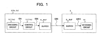
- FIG. 1 is a view of the overall configuration of a communication system 1 of a first embodiment of the present invention.
- the communication system 1 comprises, for example, an encoding apparatus 2 and a decoding apparatus 3.
- the encoding apparatus 2 corresponds to an encoding apparatus of a first invention
- the decoding apparatus 3 corresponds to a decoding destination of the present invention.
- the encoding apparatus 2 generates encoding data DBI and transmits the same to the decoding apparatus 3 via a network.
- the encoding apparatus 2 comprises, for example, an encoding circuit 10, a control circuit 11 and a transmission buffer E_BUF.
- the encoding circuit 10 corresponds to an encoding means of the first invention
- the control circuit 11 corresponds to a control means of the first invention
- the transmission buffer E_BUF corresponds to a memory means of the first invention.
- the encoding circuit 10 generates, for example, encoded video data EN composed of a plurality of frame data and outputs the same to the control circuit 11.
- the video data EN is composed of, for example, group data respectively including a plurality of frame data.
- the group data of the video data EN is composed of 5 frame data f(0) to f(4).
- the control circuit 11 writes as video data EBI the video data EN input from the encoding circuit 10 to the transmission buffer E_BUF.
- control circuit 11 designates initial offset delay time i_of, initial delay time i_d and delay time d for each of the group data composing the video data EN.
- the control circuit 11 reads the video data EBI as encoding stream data DBI from the transmission buffer E_BUF at timing designated by the initial offset delay time i_of and transmits the same to the decoding apparatus 3.
- control circuit 11 generates delay time information DTI indicating initial delay time i_d and delay time d of each of the frame data in the group data, adds the same to a position to be read first by the decoding apparatus 3 in each group data, and transmits as encoding stream data DBI to the decoding apparatus 3 at timing shown in FIG. 2 .
- the initial delay time i_d indicates timing of reading the first frame data f(0) among the plurality of frame data belonging to the group data from the receiving buffer D_BUF of the decoding apparatus 3 to the decoding circuit 14.
- the delay time i_d is designated by assuming that timing of starting an operation of writing the first frame data of the group data in the video data EBI to the transmission buffer E_BUF is 0 as shown in FIG. 2 .
- delay time d(1) to d(4) indicate time from reading of previous frame data of the frame data in the decoding order from the receiving buffer D_BUF till reading of the frame data from the receiving buffer D_BUF for the plurality of frame data belonging to the group data.
- the control circuit 11 adds the delay time information DTI indicating initial delay time i_d and delay time d of each of the group data to a position to be read prior to the frame data by the decoding apparatus 3 in the group data of the encoding stream data DBI and transmits the same to the decoding apparatus 3.
- control circuit 11 does not transmit the initial offset delay time i_of to the decoding apparatus 3.
- the control circuit 11 starts reading of the encoding stream data DBI from the transmission buffer E_BUF at a predetermined bit rate R at timing designated by the initial offset delay time i_of as shown in FIG. 2 .
- control circuit 11 suspends reading of the encoding stream data DBI from the transmission buffer E_BUF until the timing ti (3) that the frame data f(3) is written to the transmission buffer E_BUF, when a data amount stored in the transmission buffer E_BUF becomes 0 at the timing te(2) shown in FIG. 2 .
- control circuit 11 considers burst characteristics of the encoding stream data DBI to determine at least one of frame data initial offset delay time i_of and initial delay time i_d so as not to cause an overflow and underflow in the receiving buffer D_BUF of the decoding apparatus 3.
- the encoding circuit 10 generates, for example, encoded video data EN composed of a plurality of frame data and outputs the same to the control circuit 11.
- the control circuit 11 writes as video data EBI shown in FIG. 2 the video data EN to the transmission buffer E_BUF.
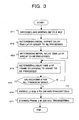
- the control circuit 11 determines initial offset delay time i_of of group data to be processed composing the video data EBI.
- the control circuit 11 determines initial delay time i_d of the group data to be processed.
- the control circuit 11 determines delay time d of frame data belonging to the group data to be processed.
- the control circuit 11 determines whether delay time d is calculated for all frame data belonging to the group data to be processed and, when determined that the calculation is completed, proceeds to the step ST6, while when determined the calculation is not completed, performs processing of the step ST4 on yet to be calculated frame data.
- the control circuit 11 adds the delay time information DTI indicating the initial delay time i_d of the group data to be processed determined in the step ST3 and the delay time d of all frame data belonging to the group data to be processed determined in the step ST4 to a position to be read prior to the frame data by the decoding apparatus 3 in the group data of the encoding stream data DBI and transmits the same to the decoding apparatus 3.
- control circuit 11 does not transmit the initial offset delay time i_of to the decoding apparatus 3.
- the control circuit 11 reads the frame data belonging to the group data to be processed from the transmission buffer E_BUF based on the initial offset delay time i_of determined in the step ST2 and transmits the same as encoding stream data DBI to the decoding apparatus 3.
- the encoding apparatus 2 does not store the initial offset delay time i_of in the delay time information DTI, so that an information amount to be transmitted from the encoding apparatus 2 to the decoding apparatus 3 can be reduced.
- the decoding apparatus 3 comprises, for example, a receiving buffer D_BUF and a decoding circuit 14.
- the decoding apparatus 3 writes video data DBI received from the encoding apparatus 2 to the receiving buffer D_BUF.
- timing of reading encoding stream data DBI from the transmission buffer E_BUF of the encoding apparatus 2 and timing of writing the same to the receiving buffer D_BUF of the decoding apparatus 3 are matched.
- the decoding circuit 14 Based on the delay time information DTI of the respective group data included in the encoding stream data EBI, the decoding circuit 14 reads frame data belonging to the group data to be processed from the transmission buffer E_BUF as video data DBO and outputs to the decoding circuit 14.
- the decoding circuit 14 starts reading of the first frame data f(0) of the above group data at timing designated by the initial delay time i_d in the delay time information DTI, then, reads frame data f(1) to (4) from the receiving buffer D_BUF based on the delay time d(1) to d(4).
- the decoding apparatus 3 can specify timing of starting reading of the first frame data f(0) of the group data without using the initial offset delay time i_of.
- the decoding circuit 14 decodes the video data DBO read from the receiving buffer D_BUF in unit of frame data.
- the decoding apparatus 3 can specify timing of reading the first frame data f(0) in the group data of the encoding stream data from the receiving buffer D_BUF based on the delay time i_d indicated by the delay time information DTI.
- the decoding apparatus 3 may decode preferentially from those having shorter initial delay time i_of among a plurality of received encoding stream data DBI successively.
- an encoding circuit 10 of the encoding apparatus 2 of the first embodiment explained above determines a data amount of the final frame data f(4) on the decoding order belonging to the group data G(0) to be processed at timing of starting writing to the receiving buffer D_BUF of the final frame data on the decoding order belonging to a sequential group data G(1) of the group data G(0) to be processed, as shown in FIG. 4 , so that the frame data belonging to the group G(0) to be processed is all read from the receiving buffer D_BUF to the decoding circuit 14 (a data amount stored in the receiving buffer D_BUF becomes 0).
- the encoding apparatus 2a in the present embodiment is the same as the encoding apparatus 2 in the first embodiment explained above except for the points below.
- the encoding circuit 10a of the encoding apparatus 2a of the present embodiment determines a data amount of the final frame data f(4) on the decoding order belonging to the group data G(0) to be processed, for example as shown in FIG. 5 , without the limitation that all frame data belonging to the group G(0) to be processed is read from the receiving buffer D_BUF to the decoding circuit 14 at timing of starting writing to the receiving buffer D BUF of the first frame data f(0) on the decoding order belonging to the sequential group data G(1) of the group data G(0) to be processed.
- frame data belonging to the group G(0) to be processed remains in the receiving buffer D_BUF at timing of starting to write to the receiving buffer D_BUF of the first frame data f(0) on the decoding order belonging to the sequential group data G(1) of the group data G(0) to be processed.
- the encoding circuit 10a does not have to insert stuffing data (for example, "0" data), which is not written to the receiving buffer D_BUF and causes deterioration of picture quality, into frame data f(4) to be decoded last belonging to the group data G(0) to be processed. Consequently, picture quality of the decoded image in accordance with the frame data f(4) can be improved.
- stuffing data for example, "0" data
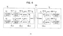
- FIG. 6 is a view of the overall configuration of a communication system 1b of the present embodiment.
- the communication system 1b comprises, for example, an encoding apparatus 2b and a decoding apparatus 3b.
- the encoding apparatus 2b multiplexes video data DBI_V and audio data DBI_A to generate encoding stream data STR and transmits the same to the decoding apparatus 3b.
- the decoding apparatus 3b demultiplexes the video data DBI_V and the audio data DBI_A from the encoding stream data STR and decodes them, respectively.
- the encoding apparatus 2 comprises, for example, an encoding circuit 10V, a control circuit 11V, a transmission buffer E_BUF_V, encoding circuit 10A, a control circuit 11A, a transmission buffer E_BUF_A and a multiplexing circuit 30 (MUX).
- the encoding circuit 10V and the transmission buffer E_BUF_V are the same as the encoding circuit 10 and the transmission buffer E_BUF shown in FIG. 1 explained in the first embodiment, respectively.
- video data EN_V corresponds to the video data EN in the first embodiment
- video data EBI_V corresponds to the video data EBI in the first embodiment
- encoding stream data DBI_V corresponds to the encoding stream data DBI in the first embodiment.
- the encoding circuit 10A generates encoded audio data EV_A.
- control circuit 11A and the transmission buffer E_BUF_A operate on audio data in the same way as operations of the control circuit 11 and the transmission buffer E_BUF on video data in the first embodiment.
- control circuit 11V in addition to the operation of the encoding circuit 10 in the first embodiment, outputs information i_of_D indicating initial offset delay time i_of to the control circuit 11A.
- the encoding circuit 11V outputs delay time information DTI indicating initial delay time i_d and delay time d of respective frame data in the group data to the control circuit 11A.
- the control circuit 11A determines initial offset delay time i of_A of video data audio data DBI_A, so that video encoding stream data DBI_V and audio encoding stream data DBI_A are synchronized based on the initial offset delay time i_of indicated by the information i_of_D input from the control circuit 11V.
- control circuit 11A reads from the transmission buffer E_BUF_A frame data at the top of the group data in the encoding stream data DBI_A based on the initial offset delay time i_of_A determined above, and outputs to the multiplexing circuit 30.
- control circuit 11A generates audio delay time DTI_A (initial delay time i_d_A) based on the video delay time DTI (initial delay time i_d) input from the control circuit 11V and adds the same to the encoding stream data DBI_A.
- control circuits 11A and 11V may determine the transfer bit rate of the encoding stream data DBI_V and DBI_A, so that the encoding stream data DBI_V and DBI_A are synchronized.
- control circuit 11A may determine a memory capacity required to store the encoding stream data DVI_A to the receiving buffer D_BUF_A of the decoding apparatus 3b based on at least one of the initial offset delay time i_of_A and video delay time DTI input from the control circuit 11V, add information indicating the memory capacity and output to the multiplexing circuit 30.
- the multiplexing circuit 30 multiplexes the video encoding stream data DBI_V input from the transmission buffer E_BUF_V and audio encoding stream data DBI_A input from the transmission buffer E_BUF_A to generate encoding stream data STR, and transmits the same to the decoding apparatus 3b.
- the decoding apparatus 3b comprises, for example, a demultiplexing circuit 31, a receiving buffer D_BUF_V, a decoding circuit 14V, a receiving buffer D_BUF_A and a decoding circuit 14A.
- a frame memory 31 demultiplexes the encoding stream data DBI_V and DVI_A from the encoding stream data STR, writes the encoding stream data DBI_V to the receiving buffer D_BUF_V, and writes the encoding stream data DBI_A to the receiving buffer D_BUF_A.
- the decoding circuit 14V reads from the receiving buffer D_BUF_V video data DBO_V based on the delay time information DTI stored in the encoding stream data DVI_V and decodes the same.
- the decoding circuit 14A reads from the receiving buffer D_BUF_A audio data DBO_A based on the delay time information DTI_A stored in the encoding stream data DVI_A and decodes the same.
- the encoding apparatus 2b by providing information i_of_D indicating initial offset delay time i_of generated by the control circuit 11V and the delay time information DTI to the control circuit 11A, video and audio can be synchronized.
- the encoding apparatus 2c of the present embodiment is the same as the encoding apparatus 2 in the first embodiment shown in FIG. 1 except for a part of processing of the control circuit 11.
- control circuit 11c of the encoding apparatus 2c of the present embodiment different processing of the control circuit 11c of the encoding apparatus 2c of the present embodiment from that of the control circuit 11 will be explained.
- FIG. 7 is a view for explaining timing of encoding stream data DBI designated by the control circuit 11c of the present embodiment.
- the control circuit 11c suspends an operation of transmitting the encoding stream data DBI to the decoding apparatus 3 before a data amount of frame data stored in the receiving buffer D_BUF becomes 0 and, after a predetermined suspension period STT, resumes transmission of the encoding stream data DBI to the decoding apparatus 3.
- control circuit 11c starts to read the first frame data f(0) on the decoding order in the group data at reference timing "0" as shown in FIG. 7 and, when coming to timing tx that the reading is completed, suspends transmission of the encoding stream data DBI (a reading operation from the transmission buffer E_BUF).
- control circuit 11c resumes transmission of the encoding stream data DBI at timing ty after a predetermined suspension period STT.
- the timing ty is designated as timing immediately before starting to decode the first frame data f(0) in the above group data in the decoding circuit 14 of the decoding apparatus 3.
- the encoding apparatus 2c by designating the timing of the encoding stream data DBI as shown in FIG. 7 , a memory capacity required by the receiving buffer D_BUF of the decoding apparatus can be reduced.
- the present invention can be applied to an encoding system for managing buffers.
Abstract
Description
- The present invention relates to an encoding apparatus and the method having a characteristic in a method of managing buffers.
- There are systems for providing content data, such as encoded video data and audio data, by transmitting to decoding apparatuses via a network, etc.
- An encoding apparatus of such systems writes encoded data to a transmission buffer and, after a predetermined initial offset delay time, reads the content data from the transmission buffer so as to transmit to an encoding apparatus.
- On the other hand, it starts by decoding.
- A
control circuit 11 suspends reading of encoding stream data DBI from a transmission buffer E_BUF until timing ti(3) that frame data f(3) is written to the transmission buffer E_BUF, when a data amount stored in the transmission buffer E_BUF becomes 0 at timing te(2) shown inFIG. 2 . - Also, the
control circuit 11 adds to the content data delay time information indicating an overflow and underflow, initial delay time until starting of the reading, and timing of reading respective frame data composing the content data from a receiving buffer and transmits the same to a receiving buffer D_BUF of adecoding apparatus 3. - A conventional encoding apparatus designates the above initial delay time by assuming that starting timing of the above initial offset delay time is 0. Therefore, the encoding apparatus adds the initial offset delay time information other than the above delay time information to the content data and transmits the same to the decoding apparatus.
- However, in the above conventional system, since the initial offset delay time information is added to the content data, there is a problem that a step for the adding processing arises and a load on processing of the encoding apparatus is heavy.
- Also, by adding the initial offset delay time information, there is a problem that an information amount of the content data becomes large.
- The present invention was made in consideration of the above related arts and has as an object thereof to provide an encoding apparatus and the method capable of reducing a processing load on the encoding apparatus and reducing a communication amount at a time.
- Also, an object of the present invention is to provide an encoding apparatus and the method capable of reducing a memory capacity required by a memory means for decoding.
-
-
FIG. 1 is a view of the overall configuration of a communication system of a first embodiment of the present invention; -
FIG. 2 is a view for explaining timing of video data EBI, encoding stream data DBI and video data DBO shown inFIG. 1 ; -
FIG. 3 is a flowchart for explaining an operation of a control circuit of the encoding apparatus shown inFIG. 1 ; -
FIG. 4 is a view for explaining limitation of a conventional encoding apparatus; -
FIG. 5 is a view for explaining an operation of a control circuit of an encoding apparatus of a second embodiment of the present invention; -
FIG. 6 is a view of the overall configuration of a communication system of a third embodiment of the present invention; and -
FIG. 7 is a view for explaining an operation of a control circuit of an encoding apparatus of a fourth embodiment of the present invention. - Below, a communication system according to embodiments of the present invention will be explained.
-
FIG. 1 is a view of the overall configuration of acommunication system 1 of a first embodiment of the present invention. - As shown in
FIG. 1 , thecommunication system 1 comprises, for example, anencoding apparatus 2 and adecoding apparatus 3. - The
encoding apparatus 2 corresponds to an encoding apparatus of a first invention, and thedecoding apparatus 3 corresponds to a decoding destination of the present invention. - The
encoding apparatus 2 generates encoding data DBI and transmits the same to thedecoding apparatus 3 via a network. - As shown in
FIG. 1 , theencoding apparatus 2 comprises, for example, anencoding circuit 10, acontrol circuit 11 and a transmission buffer E_BUF. - Here, the
encoding circuit 10 corresponds to an encoding means of the first invention, thecontrol circuit 11 corresponds to a control means of the first invention, and the transmission buffer E_BUF corresponds to a memory means of the first invention. - The
encoding circuit 10 generates, for example, encoded video data EN composed of a plurality of frame data and outputs the same to thecontrol circuit 11. - The video data EN is composed of, for example, group data respectively including a plurality of frame data.
- In the present embodiment, as an example, the group data of the video data EN is composed of 5 frame data f(0) to f(4).
- The
control circuit 11 writes as video data EBI the video data EN input from theencoding circuit 10 to the transmission buffer E_BUF. - Also, the
control circuit 11 designates initial offset delay time i_of, initial delay time i_d and delay time d for each of the group data composing the video data EN. - The
control circuit 11 reads the video data EBI as encoding stream data DBI from the transmission buffer E_BUF at timing designated by the initial offset delay time i_of and transmits the same to thedecoding apparatus 3. - Also, the
control circuit 11 generates delay time information DTI indicating initial delay time i_d and delay time d of each of the frame data in the group data, adds the same to a position to be read first by thedecoding apparatus 3 in each group data, and transmits as encoding stream data DBI to thedecoding apparatus 3 at timing shown inFIG. 2 . - The initial delay time i_d indicates timing of reading the first frame data f(0) among the plurality of frame data belonging to the group data from the receiving buffer D_BUF of the
decoding apparatus 3 to thedecoding circuit 14. Here, in the present embodiment, the delay time i_d is designated by assuming that timing of starting an operation of writing the first frame data of the group data in the video data EBI to the transmission buffer E_BUF is 0 as shown inFIG. 2 . - Also, delay time d(1) to d(4) indicate time from reading of previous frame data of the frame data in the decoding order from the receiving buffer D_BUF till reading of the frame data from the receiving buffer D_BUF for the plurality of frame data belonging to the group data.
- The
control circuit 11 adds the delay time information DTI indicating initial delay time i_d and delay time d of each of the group data to a position to be read prior to the frame data by thedecoding apparatus 3 in the group data of the encoding stream data DBI and transmits the same to thedecoding apparatus 3. - Namely, the
control circuit 11 does not transmit the initial offset delay time i_of to thedecoding apparatus 3. - The
control circuit 11 starts reading of the encoding stream data DBI from the transmission buffer E_BUF at a predetermined bit rate R at timing designated by the initial offset delay time i_of as shown inFIG. 2 . - Then, the
control circuit 11 suspends reading of the encoding stream data DBI from the transmission buffer E_BUF until the timing ti (3) that the frame data f(3) is written to the transmission buffer E_BUF, when a data amount stored in the transmission buffer E_BUF becomes 0 at the timing te(2) shown inFIG. 2 . - Also, the
control circuit 11 considers burst characteristics of the encoding stream data DBI to determine at least one of frame data initial offset delay time i_of and initial delay time i_d so as not to cause an overflow and underflow in the receiving buffer D_BUF of thedecoding apparatus 3. - Below, an operation example of the
encoding apparatus 2 shown inFIG. 1 will be explained. - The
encoding circuit 10 generates, for example, encoded video data EN composed of a plurality of frame data and outputs the same to thecontrol circuit 11. - The
control circuit 11 writes as video data EBI shown inFIG. 2 the video data EN to the transmission buffer E_BUF. - The
control circuit 11 determines initial offset delay time i_of of group data to be processed composing the video data EBI. - The
control circuit 11 determines initial delay time i_d of the group data to be processed. - The
control circuit 11 determines delay time d of frame data belonging to the group data to be processed. - The
control circuit 11 determines whether delay time d is calculated for all frame data belonging to the group data to be processed and, when determined that the calculation is completed, proceeds to the step ST6, while when determined the calculation is not completed, performs processing of the step ST4 on yet to be calculated frame data. - The
control circuit 11 adds the delay time information DTI indicating the initial delay time i_d of the group data to be processed determined in the step ST3 and the delay time d of all frame data belonging to the group data to be processed determined in the step ST4 to a position to be read prior to the frame data by thedecoding apparatus 3 in the group data of the encoding stream data DBI and transmits the same to thedecoding apparatus 3. - Namely, the
control circuit 11 does not transmit the initial offset delay time i_of to thedecoding apparatus 3. - The
control circuit 11 reads the frame data belonging to the group data to be processed from the transmission buffer E_BUF based on the initial offset delay time i_of determined in the step ST2 and transmits the same as encoding stream data DBI to thedecoding apparatus 3. - As explained above, according to the
communication system 1, theencoding apparatus 2 does not store the initial offset delay time i_of in the delay time information DTI, so that an information amount to be transmitted from theencoding apparatus 2 to thedecoding apparatus 3 can be reduced. - As shown in
FIG. 1 , thedecoding apparatus 3 comprises, for example, a receiving buffer D_BUF and adecoding circuit 14. - The
decoding apparatus 3 writes video data DBI received from theencoding apparatus 2 to the receiving buffer D_BUF. - In the present embodiment, timing of reading encoding stream data DBI from the transmission buffer E_BUF of the
encoding apparatus 2 and timing of writing the same to the receiving buffer D_BUF of thedecoding apparatus 3 are matched. - Based on the delay time information DTI of the respective group data included in the encoding stream data EBI, the
decoding circuit 14 reads frame data belonging to the group data to be processed from the transmission buffer E_BUF as video data DBO and outputs to thedecoding circuit 14. - Namely, the
decoding circuit 14 starts reading of the first frame data f(0) of the above group data at timing designated by the initial delay time i_d in the delay time information DTI, then, reads frame data f(1) to (4) from the receiving buffer D_BUF based on the delay time d(1) to d(4). - In the present embodiment, since the initial delay time i_d is designated by assuming that timing of starting writing of encoding stream data DBI to the receiving buffer D_BUF is 0, the
decoding apparatus 3 can specify timing of starting reading of the first frame data f(0) of the group data without using the initial offset delay time i_of. - The
decoding circuit 14 decodes the video data DBO read from the receiving buffer D_BUF in unit of frame data. - Also, according to the
communication system 1, as shown inFIG. 2 , by designating the delay time i_d by assuming that timing of starting an operation of writing the first frame data of the group data in the video data EBI to the transmission buffer E_BUF is 0, thedecoding apparatus 3 can specify timing of reading the first frame data f(0) in the group data of the encoding stream data from the receiving buffer D_BUF based on the delay time i_d indicated by the delay time information DTI. - Note that while the case of using
single encoding apparatus 2 was explained as an example inFIG. 1 , in the case of transmitting encoding stream data DBI from a plurality ofencoding apparatuses 2 tosingle decoding apparatus 3, thedecoding apparatus 3 may decode preferentially from those having shorter initial delay time i_of among a plurality of received encoding stream data DBI successively. - As a result, a highly responsive system can be realized.
- For example, an
encoding circuit 10 of theencoding apparatus 2 of the first embodiment explained above determines a data amount of the final frame data f(4) on the decoding order belonging to the group data G(0) to be processed at timing of starting writing to the receiving buffer D_BUF of the final frame data on the decoding order belonging to a sequential group data G(1) of the group data G(0) to be processed, as shown inFIG. 4 , so that the frame data belonging to the group G(0) to be processed is all read from the receiving buffer D_BUF to the decoding circuit 14 (a data amount stored in the receiving buffer D_BUF becomes 0). - The
encoding apparatus 2a in the present embodiment is the same as theencoding apparatus 2 in the first embodiment explained above except for the points below. - Namely, the
encoding circuit 10a of theencoding apparatus 2a of the present embodiment determines a data amount of the final frame data f(4) on the decoding order belonging to the group data G(0) to be processed, for example as shown inFIG. 5 , without the limitation that all frame data belonging to the group G(0) to be processed is read from the receiving buffer D_BUF to thedecoding circuit 14 at timing of starting writing to the receiving buffer D BUF of the first frame data f(0) on the decoding order belonging to the sequential group data G(1) of the group data G(0) to be processed. - Therefore, in the present embodiment, there are some cases where frame data belonging to the group G(0) to be processed remains in the receiving buffer D_BUF at timing of starting to write to the receiving buffer D_BUF of the first frame data f(0) on the decoding order belonging to the sequential group data G(1) of the group data G(0) to be processed.
- As a result, the
encoding circuit 10a does not have to insert stuffing data (for example, "0" data), which is not written to the receiving buffer D_BUF and causes deterioration of picture quality, into frame data f(4) to be decoded last belonging to the group data G(0) to be processed. Consequently, picture quality of the decoded image in accordance with the frame data f(4) can be improved. -
FIG. 6 is a view of the overall configuration of acommunication system 1b of the present embodiment. - As shown in
FIG. 6 , thecommunication system 1b comprises, for example, anencoding apparatus 2b and a decoding apparatus 3b. - The
encoding apparatus 2b multiplexes video data DBI_V and audio data DBI_A to generate encoding stream data STR and transmits the same to the decoding apparatus 3b. - The decoding apparatus 3b demultiplexes the video data DBI_V and the audio data DBI_A from the encoding stream data STR and decodes them, respectively.
- As shown in
FIG. 6 , theencoding apparatus 2 comprises, for example, anencoding circuit 10V, acontrol circuit 11V, a transmission buffer E_BUF_V, encodingcircuit 10A, a control circuit 11A, a transmission buffer E_BUF_A and a multiplexing circuit 30 (MUX). - The
encoding circuit 10V and the transmission buffer E_BUF_V are the same as theencoding circuit 10 and the transmission buffer E_BUF shown inFIG. 1 explained in the first embodiment, respectively. - Here, video data EN_V corresponds to the video data EN in the first embodiment, video data EBI_V corresponds to the video data EBI in the first embodiment, and encoding stream data DBI_V corresponds to the encoding stream data DBI in the first embodiment.
- The
encoding circuit 10A generates encoded audio data EV_A. - The control circuit 11A and the transmission buffer E_BUF_A operate on audio data in the same way as operations of the
control circuit 11 and the transmission buffer E_BUF on video data in the first embodiment. - In the present embodiment, the
control circuit 11V, in addition to the operation of theencoding circuit 10 in the first embodiment, outputs information i_of_D indicating initial offset delay time i_of to the control circuit 11A. - Also, the
encoding circuit 11V outputs delay time information DTI indicating initial delay time i_d and delay time d of respective frame data in the group data to the control circuit 11A. - The control circuit 11A determines initial offset delay time i of_A of video data audio data DBI_A, so that video encoding stream data DBI_V and audio encoding stream data DBI_A are synchronized based on the initial offset delay time i_of indicated by the information i_of_D input from the
control circuit 11V. - Then, the control circuit 11A reads from the transmission buffer E_BUF_A frame data at the top of the group data in the encoding stream data DBI_A based on the initial offset delay time i_of_A determined above, and outputs to the multiplexing circuit 30.
- Also, the control circuit 11A generates audio delay time DTI_A (initial delay time i_d_A) based on the video delay time DTI (initial delay time i_d) input from the
control circuit 11V and adds the same to the encoding stream data DBI_A. - Also, the
control circuits 11A and 11V may determine the transfer bit rate of the encoding stream data DBI_V and DBI_A, so that the encoding stream data DBI_V and DBI_A are synchronized. - Also, the control circuit 11A may determine a memory capacity required to store the encoding stream data DVI_A to the receiving buffer D_BUF_A of the decoding apparatus 3b based on at least one of the initial offset delay time i_of_A and video delay time DTI input from the
control circuit 11V, add information indicating the memory capacity and output to the multiplexing circuit 30. - The multiplexing circuit 30 multiplexes the video encoding stream data DBI_V input from the transmission buffer E_BUF_V and audio encoding stream data DBI_A input from the transmission buffer E_BUF_A to generate encoding stream data STR, and transmits the same to the decoding apparatus 3b.
- As shown in
FIG. 6 , the decoding apparatus 3b comprises, for example, ademultiplexing circuit 31, a receiving buffer D_BUF_V, a decoding circuit 14V, a receiving buffer D_BUF_A and a decoding circuit 14A. - A
frame memory 31 demultiplexes the encoding stream data DBI_V and DVI_A from the encoding stream data STR, writes the encoding stream data DBI_V to the receiving buffer D_BUF_V, and writes the encoding stream data DBI_A to the receiving buffer D_BUF_A. - Here, the decoding circuit 14V reads from the receiving buffer D_BUF_V video data DBO_V based on the delay time information DTI stored in the encoding stream data DVI_V and decodes the same.
- Also, the decoding circuit 14A reads from the receiving buffer D_BUF_A audio data DBO_A based on the delay time information DTI_A stored in the encoding stream data DVI_A and decodes the same.
- As explained above, according to the
communication system 1b of the present embodiment, even in the case of multiplexing video and audio for transmitting, the same effects as those in the first embodiment can be obtained. - Also, according to the
encoding apparatus 2b, by providing information i_of_D indicating initial offset delay time i_of generated by thecontrol circuit 11V and the delay time information DTI to the control circuit 11A, video and audio can be synchronized. - The
encoding apparatus 2c of the present embodiment is the same as theencoding apparatus 2 in the first embodiment shown inFIG. 1 except for a part of processing of thecontrol circuit 11. - Below, different processing of the
control circuit 11c of theencoding apparatus 2c of the present embodiment from that of thecontrol circuit 11 will be explained. -
FIG. 7 is a view for explaining timing of encoding stream data DBI designated by thecontrol circuit 11c of the present embodiment. - As shown in
FIG. 7 , thecontrol circuit 11c suspends an operation of transmitting the encoding stream data DBI to thedecoding apparatus 3 before a data amount of frame data stored in the receiving buffer D_BUF becomes 0 and, after a predetermined suspension period STT, resumes transmission of the encoding stream data DBI to thedecoding apparatus 3. - Specifically, the
control circuit 11c starts to read the first frame data f(0) on the decoding order in the group data at reference timing "0" as shown inFIG. 7 and, when coming to timing tx that the reading is completed, suspends transmission of the encoding stream data DBI (a reading operation from the transmission buffer E_BUF). - Then, the
control circuit 11c resumes transmission of the encoding stream data DBI at timing ty after a predetermined suspension period STT. - In the present embodiment, the timing ty is designated as timing immediately before starting to decode the first frame data f(0) in the above group data in the
decoding circuit 14 of thedecoding apparatus 3. - As explained above, according to the
encoding apparatus 2c, by designating the timing of the encoding stream data DBI as shown inFIG. 7 , a memory capacity required by the receiving buffer D_BUF of the decoding apparatus can be reduced. - The present invention can be applied to an encoding system for managing buffers.
- Particular aspects are:
- 1. An encoding apparatus, comprising
an encoding means for generating a plurality of encoding data to be decoded in a predetermined order,
a memory means for storing said encoding data generated by said encoding means, and
a control means for reading said encoding data from said memory means and transmitting to a decoding destination;
wherein said control means determines first delay time from writing of said encoding data being first on the decoding order among said plurality of encoding data generated by said encoding means till reading and transmitting the same to the decoding destination, determines second delay time from receiving of said encoding data being first on the decoding order among said plurality of encoding data at said decoding destination to decoding of the first encoding data, transmits delay time information indicating said second delay time to said decoding destination, and transmits said first encoding data being first on the decoding order to said decoding destination based on said determined first delay time. - 2. An encoding apparatus as set forth in example 1, wherein said encoding means determines said second delay time indicating timing of decoding said first encoding data by assuming that timing of starting an operation of reading said first encoding data from said memory means and transmitting the same to a decoding destination is reference timing.
- 3. An encoding apparatus as set forth in example 2, wherein said encoding means determines said second delay time by assuming that said reference timing is 0.
- 4. An encoding apparatus as set forth in example 1, wherein said control means determines third delay time from decoding previous encoding data of said encoding data on the decoding order at said decoding destination till decoding the encoding data for each of said plurality of encoding data, and transmits said delay time information further including the third delay time to said decoding destination.
- 5. An encoding apparatus as set forth in example 1, wherein said control means does not transmit information indicating said first delay time to said decoding destination.
- 6. An encoding apparatus as set forth in example 1, wherein,
when decoding said encoding data received at said decoding destination after holding it in a decoding memory means,
said encoding means determines said second delay time from writing of said first encoding data to said decoding memory means of said decoding destination till reading of the first encoding data from said decoding memory means and decoding. - 7. An encoding apparatus as set forth in example 6, wherein, for each group constituted by said plurality of encoding data, said control means determines said delay time information on said encoding data belonging to the group and transmits the delay time information to said decoding destination.
- 8. An encoding apparatus as set forth in example 7, wherein said control means approves that said encoding data belonging to a group to be processed remains in a decoding memory means to be stored at timing of starting to write said first encoding data on the decoding order belonging to a subsequent group of the group to be processed to said decoding memory means.
- 9. An encoding apparatus as set forth in example 1, wherein, when said encoding data of video and said encoding data of audio are multiplexed to be transmitted to said decoding destination, said control means determines at least one of a memory capacity of said memory means for storing said encoding data of said audio and said second delay time of said encoding data of said audio based on at least one of said first delay time and second delay time determined for said video encoding data.
- 10. An encoding apparatus as set forth in example 1, wherein, when said encoding data of video and said encoding data of audio are multiplexed to be transmitted to said decoding destination, said control means determines said first delay time of said encoding data of said video and said first delay time of said encoding data of said audio, so that said video and said audio are synchronized.
- 11. An encoding apparatus as set forth in example 1, wherein, when said encoding data of video and said encoding data of audio are multiplexed to be transmitted to said decoding destination, said control means determines a bit rate at the time of transmitting said encoding data of said video and a bit rate at the time of transmitting said encoding data of said audio, so that said video and said audio are synchronized.
- 12. An encoding apparatus as set forth in example 1, wherein said encoding means determines at least one of said first delay time and said second delay time by considering burst characteristics of said encoding data, so that an overflow and underflow are not caused in said second memory means.
- 13. An encoding apparatus, comprising
an encoding means for generating a plurality of encoding data to be decoded in a predetermined order,
a memory means for storing said encoding data generated by said encoding means, and
a control means for transmitting said encoding data read from said memory means together with information for designating timing of decoding said encoding data at a decoding destination to said decoding destination;
wherein said control means suspends reading of said encoding data from said memory means before a data amount of said encoding data stored in said memory means becomes 0 and, after a predetermined suspension period, reads said encoding data from said memory means to resume an operation of transmitting to said decoding destination. - 14. An encoding apparatus as set forth in example 13, wherein said control means starts said suspension period at timing of completing an operation of reading said first encoding data on the decoding order from said memory means and transmitting to said decoding destination, and ends said suspension period at timing immediately before the first encoding data is read from said decoding memory means at said decoding destination and decoded.
- 15. An encoding method, comprising:
- a first step of determining first delay time from writing of said encoding data being first on the decoding order among a plurality of encoding data to a memory means till reading and transmitting the same to a decoding destination,
- a second step of determining second delay time from receiving of said first encoding data among said plurality of encoding data at said decoding destination till decoding of the first encoding data, and
- a third step of transmitting delay time information indicating said second delay time determined in said second step to said decoding destination and transmitting said first encoding data on the decoding order to said decoding destination based on the first delay time determined in said first step.
- 16. An encoding method, comprising
a first step of writing a plurality of encoding data to be decoded in a predetermined order to a memory means, and
a second step of reading said encoding data from said memory means together with information for designating timing of decoding said encoding data at a decoding destination and transmitting the same to said decoding destination;
wherein said second step suspends reading of said encoding data from said memory means before a data amount of said encoding data stored in said memory means becomes 0 and, after a predetermined suspension period, resumes reading of said encoding data from said memory means. -
- 2, 2C... encoding apparatus
- 3... decoding apparatus
- 10, 10a, 10V, 10A... encoding circuit
- 11, 11c, 11V, 11A... control circuit
- E_BUF, E_BUF_V, E_BUF_A... transmission buffer
- D_BUF, D_BUF_V, D_BUF_A... receiving buffer
- 14, 14V, 14A... decoding circuit
Claims (4)
- An encoding method comprising steps of:encoding image data to generate a bitstream;generating delay offset information indicating delay time from providing the bitstream to an encoder buffer until providing the bit stream to a decoder buffer; andtransmitting the delay offset information generated in said generating step and the bit stream in said encoding step.
- The encoding method of claim 1, wherein
said transmitting step comprises transmitting the delay offset information generated in said generating step by adding the delay offset information into the bitstream generated in said encoding step. - An encoding apparatus comprising:encoding means configured to encode image data to generate a bitstream;control means configured to generate delay offset information indicating delay time from providing the bitstream to an encoder buffer until providing the bit stream to a decoder buffer; andwherein the control means is further configured to transmit the delay offset information generated by the control means and the bit stream encoded by the encoding means;
- The decoding apparatus according to claim 3, wherein
the transmitting means is configured to transmit the delay offset information generated in the control means by adding the delay offset information into the bitstream generated in said encoding means.
Applications Claiming Priority (3)
| Application Number | Priority Date | Filing Date | Title |
|---|---|---|---|
| JP2002349287A JP2004186840A (en) | 2002-11-29 | 2002-11-29 | Method for using non-initialized buffer model |
| JP2002356054A JP2004193687A (en) | 2002-12-06 | 2002-12-06 | Method using non-initialized buffer model |
| EP03775951.1A EP1581004B1 (en) | 2002-11-29 | 2003-11-28 | Encoder and its method |
Related Parent Applications (3)
| Application Number | Title | Priority Date | Filing Date |
|---|---|---|---|
| EP03775951.1 Division | 2003-11-28 | ||
| EP03775951.1A Division EP1581004B1 (en) | 2002-11-29 | 2003-11-28 | Encoder and its method |
| EP03775951.1A Division-Into EP1581004B1 (en) | 2002-11-29 | 2003-11-28 | Encoder and its method |
Publications (2)
| Publication Number | Publication Date |
|---|---|
| EP2557787A1 true EP2557787A1 (en) | 2013-02-13 |
| EP2557787B1 EP2557787B1 (en) | 2016-02-24 |
Family
ID=32473665
Family Applications (5)
| Application Number | Title | Priority Date | Filing Date |
|---|---|---|---|
| EP12184984.8A Expired - Fee Related EP2557786B1 (en) | 2002-11-29 | 2003-11-28 | Delay controlled decoding apparatus and method |
| EP12184986.3A Expired - Fee Related EP2557787B1 (en) | 2002-11-29 | 2003-11-28 | Encoding apparatus and the method |
| EP20120184978 Withdrawn EP2557785A1 (en) | 2002-11-29 | 2003-11-28 | Delay controlled decoding method and apparatus |
| EP03775951.1A Expired - Fee Related EP1581004B1 (en) | 2002-11-29 | 2003-11-28 | Encoder and its method |
| EP20120184992 Withdrawn EP2557788A1 (en) | 2002-11-29 | 2003-11-28 | Encoding apparatus and the method |
Family Applications Before (1)
| Application Number | Title | Priority Date | Filing Date |
|---|---|---|---|
| EP12184984.8A Expired - Fee Related EP2557786B1 (en) | 2002-11-29 | 2003-11-28 | Delay controlled decoding apparatus and method |
Family Applications After (3)
| Application Number | Title | Priority Date | Filing Date |
|---|---|---|---|
| EP20120184978 Withdrawn EP2557785A1 (en) | 2002-11-29 | 2003-11-28 | Delay controlled decoding method and apparatus |
| EP03775951.1A Expired - Fee Related EP1581004B1 (en) | 2002-11-29 | 2003-11-28 | Encoder and its method |
| EP20120184992 Withdrawn EP2557788A1 (en) | 2002-11-29 | 2003-11-28 | Encoding apparatus and the method |
Country Status (4)
| Country | Link |
|---|---|
| US (5) | US8798167B2 (en) |
| EP (5) | EP2557786B1 (en) |
| KR (3) | KR101001232B1 (en) |
| WO (1) | WO2004052015A1 (en) |
Families Citing this family (8)
| Publication number | Priority date | Publication date | Assignee | Title |
|---|---|---|---|---|
| JP4289138B2 (en) * | 2003-12-09 | 2009-07-01 | ソニー株式会社 | Data processing apparatus and method and encoding apparatus |
| JP5052220B2 (en) * | 2007-06-19 | 2012-10-17 | パナソニック株式会社 | Video encoding device |
| US7616133B2 (en) * | 2008-01-16 | 2009-11-10 | Micron Technology, Inc. | Data bus inversion apparatus, systems, and methods |
| US9116828B2 (en) | 2008-06-11 | 2015-08-25 | Micron Technology, Inc. | Data bus inversion usable in a memory system |
| RU2587467C2 (en) | 2011-06-30 | 2016-06-20 | МАЙКРОСОФТ ТЕКНОЛОДЖИ ЛАЙСЕНСИНГ, ЭлЭлСи | Reducing delays in video encoding and decoding |
| WO2014006921A1 (en) * | 2012-07-06 | 2014-01-09 | Sharp Kabushiki Kaisha | Electronic devices for signaling sub-picture based hypothetical reference decoder parameters |
| EP2920963A4 (en) * | 2012-11-14 | 2016-07-06 | California Inst Of Techn | Coding for real-time streaming under packet erasures |
| WO2016117964A1 (en) * | 2015-01-23 | 2016-07-28 | 엘지전자 주식회사 | Method and device for transmitting and receiving broadcast signal for restoring pulled-down signal |
Citations (4)
| Publication number | Priority date | Publication date | Assignee | Title |
|---|---|---|---|---|
| WO1997038532A1 (en) * | 1996-04-04 | 1997-10-16 | Nds Limited | Buffer control in a coded data transmission system |
| US6151359A (en) * | 1994-10-21 | 2000-11-21 | Lucent Technologies Inc. | Method of video buffer verification |
| WO2001080570A2 (en) * | 2000-04-19 | 2001-10-25 | General Instrument Corporation | Rate control and buffer protection for variable bit rate video programs over a constant rate channel |
| WO2002025951A2 (en) * | 2000-09-20 | 2002-03-28 | General Instrument Corporation | Method and apparatus for determining a transmission bit rate in a statistical multiplexer |
Family Cites Families (61)
| Publication number | Priority date | Publication date | Assignee | Title |
|---|---|---|---|---|
| US2307206A (en) * | 1940-03-14 | 1943-01-05 | Armour & Co | Spraying device |
| US3326470A (en) * | 1965-04-27 | 1967-06-20 | Babcock & Wilcox Co | Liquid atomizer |
| US4218221A (en) * | 1978-01-30 | 1980-08-19 | Cottell Eric Charles | Production of fuels |
| US4517670A (en) * | 1983-06-15 | 1985-05-14 | General Electric Company | Preemptive bid communication system |
| JPS61259781A (en) * | 1985-05-13 | 1986-11-18 | Toa Nenryo Kogyo Kk | Vibrator for ultrasonic pulverization having curved multistage edge part |
| AT389235B (en) * | 1987-05-19 | 1989-11-10 | Stuckart Wolfgang | METHOD FOR CLEANING LIQUIDS BY MEANS OF ULTRASOUND AND DEVICES FOR CARRYING OUT THIS METHOD |
| GB9012538D0 (en) * | 1990-06-05 | 1990-07-25 | Philips Nv | Coding of video signals |
| US5159447A (en) * | 1991-05-23 | 1992-10-27 | At&T Bell Laboratories | Buffer control for variable bit-rate channel |
| US5665383A (en) * | 1993-02-22 | 1997-09-09 | Vivorx Pharmaceuticals, Inc. | Methods for the preparation of immunostimulating agents for in vivo delivery |
| JP2550856B2 (en) * | 1993-05-17 | 1996-11-06 | 日本電気株式会社 | Video coding preprocessor |
| JP2580955B2 (en) * | 1993-06-23 | 1997-02-12 | 日本電気株式会社 | Data multiplexing device and separating device |
| US6020277A (en) * | 1994-06-23 | 2000-02-01 | Kimberly-Clark Corporation | Polymeric strands with enhanced tensile strength, nonwoven webs including such strands, and methods for making same |
| US6010592A (en) * | 1994-06-23 | 2000-01-04 | Kimberly-Clark Corporation | Method and apparatus for increasing the flow rate of a liquid through an orifice |
| US5543853A (en) * | 1995-01-19 | 1996-08-06 | At&T Corp. | Encoder/decoder buffer control for variable bit-rate channel |
| JP2770786B2 (en) * | 1995-06-05 | 1998-07-02 | 日本電気株式会社 | Multiplexed ATM / STM converter for structured data |
| US5868153A (en) * | 1995-12-21 | 1999-02-09 | Kimberly-Clark Worldwide, Inc. | Ultrasonic liquid flow control apparatus and method |
| ZA969680B (en) * | 1995-12-21 | 1997-06-12 | Kimberly Clark Co | Ultrasonic liquid fuel injection on apparatus and method |
| US6053424A (en) * | 1995-12-21 | 2000-04-25 | Kimberly-Clark Worldwide, Inc. | Apparatus and method for ultrasonically producing a spray of liquid |
| US6018765A (en) * | 1996-01-23 | 2000-01-25 | Storage Concepts, Inc. | Multi-channel multimedia data server |
| CA2196622C (en) * | 1996-02-06 | 2001-10-16 | Hiroshi Jinzenji | Network data distribution system |
| JP2872104B2 (en) | 1996-05-14 | 1999-03-17 | 株式会社グラフィックス・コミュニケーション・ラボラトリーズ | Time stamp adding apparatus and method, and moving image compression / expansion transmission system and method using the same |
| EP0925061B1 (en) * | 1996-08-22 | 2005-12-28 | Jagotec Ag | Compositions comprising microparticles of water-insoluble substances and method for preparing same |
| US6188700B1 (en) * | 1996-11-07 | 2001-02-13 | Sony Corporation | Method and apparatus for encoding MPEG signals using variable rate encoding and dynamically varying transmission buffers |
| EP0841820A3 (en) * | 1996-11-08 | 2005-11-09 | Matsushita Electric Industrial Co., Ltd. | Method and apparatus for encoding, multiplexing and transmitting a video signal |
| US6011868A (en) * | 1997-04-04 | 2000-01-04 | Hewlett-Packard Company | Bitstream quality analyzer |
| US6101195A (en) * | 1997-05-28 | 2000-08-08 | Sarnoff Corporation | Timing correction method and apparatus |
| US6282240B1 (en) * | 1997-09-03 | 2001-08-28 | Oki Electric Industry Co., Ltd. | Picture coder, picture decoder, and transmission system |
| US6366704B1 (en) * | 1997-12-01 | 2002-04-02 | Sharp Laboratories Of America, Inc. | Method and apparatus for a delay-adaptive rate control scheme for the frame layer |
| JP3642550B2 (en) * | 1998-03-12 | 2005-04-27 | 株式会社日立国際電気 | Video signal transmission method and apparatus |
| JPH11262001A (en) * | 1998-03-16 | 1999-09-24 | Hitachi Denshi Ltd | Method for calculating time stamp value in encoding transmission system |
| US6023233A (en) * | 1998-03-20 | 2000-02-08 | Craven; Peter G. | Data rate control for variable rate compression systems |
| US6091776A (en) * | 1998-05-26 | 2000-07-18 | C-Cube Microsystems, Inc. | Delay balanced video encoder system |
| JP3422686B2 (en) | 1998-06-12 | 2003-06-30 | 三菱電機株式会社 | Data decoding device and data decoding method |
| US6167084A (en) * | 1998-08-27 | 2000-12-26 | Motorola, Inc. | Dynamic bit allocation for statistical multiplexing of compressed and uncompressed digital video signals |
| US6804825B1 (en) * | 1998-11-30 | 2004-10-12 | Microsoft Corporation | Video on demand methods and systems |
| US6637031B1 (en) * | 1998-12-04 | 2003-10-21 | Microsoft Corporation | Multimedia presentation latency minimization |
| US6811813B1 (en) * | 1999-05-19 | 2004-11-02 | Sarnoff Corporation | Method of coating micrometer sized inorganic particles |
| EP1096804B1 (en) * | 1999-10-25 | 2006-12-13 | Matsushita Electric Industrial Co., Ltd. | Video decoding method, video decoding apparatus, and program storage media |
| US6700893B1 (en) * | 1999-11-15 | 2004-03-02 | Koninklijke Philips Electronics N.V. | System and method for controlling the delay budget of a decoder buffer in a streaming data receiver |
| US6481645B1 (en) * | 2000-05-22 | 2002-11-19 | Shurflo Pump Mfg. Company, Inc. | Condiment dispensing nozzle apparatus and method |
| JP2004505390A (en) * | 2000-07-31 | 2004-02-19 | コーニンクレッカ フィリップス エレクトロニクス エヌ ヴィ | Non-contact data carrier with controllable power supply voltage generating means |
| JP3668110B2 (en) * | 2000-08-31 | 2005-07-06 | 株式会社東芝 | Image transmission system and image transmission method |
| US6817541B2 (en) * | 2000-09-01 | 2004-11-16 | Del Industries, Inc. | Ozone systems and methods for agricultural applications |
| KR100357689B1 (en) * | 2000-11-13 | 2002-10-19 | 삼성전자 주식회사 | Apparatus for real time transmission of variable bit rate mpeg video traffic with consistent quality |
| US20020191116A1 (en) * | 2001-04-24 | 2002-12-19 | Damien Kessler | System and data format for providing seamless stream switching in a digital video recorder |
| US20030048692A1 (en) * | 2001-09-07 | 2003-03-13 | Bernard Cohen | Apparatus for mixing, atomizing, and applying liquid coatings |
| US6883724B2 (en) * | 2001-09-19 | 2005-04-26 | Nanomist Systems, Llc | Method and device for production, extraction and delivery of mist with ultrafine droplets |
| US6889528B2 (en) * | 2001-10-22 | 2005-05-10 | Council Of Scientific & Industrial Research | Process of making rare earth doped optical fiber |
| US7976855B2 (en) * | 2002-04-30 | 2011-07-12 | Kimberly-Clark Worldwide, Inc. | Metal ion modified high surface area materials for odor removal and control |
| CN1623347A (en) * | 2002-05-07 | 2005-06-01 | 三菱电机株式会社 | Base station for wireless communication, wireless communication method, and mobile station |
| US20040057446A1 (en) * | 2002-07-16 | 2004-03-25 | Nokia Corporation | Method for enabling packet transfer delay compensation in multimedia streaming |
| JP3534742B1 (en) * | 2002-10-03 | 2004-06-07 | 株式会社エヌ・ティ・ティ・ドコモ | Moving picture decoding method, moving picture decoding apparatus, and moving picture decoding program |
| US8582659B2 (en) * | 2003-09-07 | 2013-11-12 | Microsoft Corporation | Determining a decoding time stamp from buffer fullness |
| US7438875B2 (en) * | 2003-10-16 | 2008-10-21 | Kimberly-Clark Worldwide, Inc. | Method for reducing odor using metal-modified silica particles |
| JP4482322B2 (en) * | 2003-12-18 | 2010-06-16 | 浜松ホトニクス株式会社 | Fine particle production method and production apparatus |
| DE102004025836B3 (en) * | 2004-05-24 | 2005-12-22 | Dr. Hielscher Gmbh | Method and device for introducing ultrasound into a flowable medium |
| US7156201B2 (en) * | 2004-11-04 | 2007-01-02 | Advanced Ultrasonic Solutions, Inc. | Ultrasonic rod waveguide-radiator |
| US7703698B2 (en) * | 2006-09-08 | 2010-04-27 | Kimberly-Clark Worldwide, Inc. | Ultrasonic liquid treatment chamber and continuous flow mixing system |
| US7424883B2 (en) * | 2006-01-23 | 2008-09-16 | Kimberly-Clark Worldwide, Inc. | Ultrasonic fuel injector |
| US9283188B2 (en) * | 2006-09-08 | 2016-03-15 | Kimberly-Clark Worldwide, Inc. | Delivery systems for delivering functional compounds to substrates and processes of using the same |
| US20080069887A1 (en) * | 2006-09-15 | 2008-03-20 | 3M Innovative Properties Company | Method for nanoparticle surface modification |
-
2003
- 2003-11-28 EP EP12184984.8A patent/EP2557786B1/en not_active Expired - Fee Related
- 2003-11-28 KR KR1020057009697A patent/KR101001232B1/en active IP Right Grant
- 2003-11-28 KR KR1020107017887A patent/KR101022743B1/en active IP Right Grant
- 2003-11-28 US US10/536,022 patent/US8798167B2/en not_active Expired - Fee Related
- 2003-11-28 KR KR1020107017888A patent/KR101022744B1/en active IP Right Grant
- 2003-11-28 WO PCT/JP2003/015257 patent/WO2004052015A1/en active Application Filing
- 2003-11-28 EP EP12184986.3A patent/EP2557787B1/en not_active Expired - Fee Related
- 2003-11-28 EP EP20120184978 patent/EP2557785A1/en not_active Withdrawn
- 2003-11-28 EP EP03775951.1A patent/EP1581004B1/en not_active Expired - Fee Related
- 2003-11-28 EP EP20120184992 patent/EP2557788A1/en not_active Withdrawn
-
2011
- 2011-04-28 US US13/096,752 patent/US20110280320A1/en not_active Abandoned
- 2011-04-28 US US13/096,730 patent/US20110200096A1/en not_active Abandoned
- 2011-04-28 US US13/096,709 patent/US9516361B2/en not_active Expired - Lifetime
- 2011-04-28 US US13/096,787 patent/US9654812B2/en not_active Expired - Lifetime
Patent Citations (4)
| Publication number | Priority date | Publication date | Assignee | Title |
|---|---|---|---|---|
| US6151359A (en) * | 1994-10-21 | 2000-11-21 | Lucent Technologies Inc. | Method of video buffer verification |
| WO1997038532A1 (en) * | 1996-04-04 | 1997-10-16 | Nds Limited | Buffer control in a coded data transmission system |
| WO2001080570A2 (en) * | 2000-04-19 | 2001-10-25 | General Instrument Corporation | Rate control and buffer protection for variable bit rate video programs over a constant rate channel |
| WO2002025951A2 (en) * | 2000-09-20 | 2002-03-28 | General Instrument Corporation | Method and apparatus for determining a transmission bit rate in a statistical multiplexer |
Also Published As
| Publication number | Publication date |
|---|---|
| EP2557788A1 (en) | 2013-02-13 |
| KR20100097236A (en) | 2010-09-02 |
| EP1581004A1 (en) | 2005-09-28 |
| EP1581004A4 (en) | 2010-02-24 |
| WO2004052015A1 (en) | 2004-06-17 |
| US8798167B2 (en) | 2014-08-05 |
| KR101022743B1 (en) | 2011-03-22 |
| EP2557786B1 (en) | 2016-02-24 |
| US20110280320A1 (en) | 2011-11-17 |
| KR101001232B1 (en) | 2010-12-17 |
| US20110200118A1 (en) | 2011-08-18 |
| US9516361B2 (en) | 2016-12-06 |
| US20110200096A1 (en) | 2011-08-18 |
| US9654812B2 (en) | 2017-05-16 |
| EP2557787B1 (en) | 2016-02-24 |
| KR20050071714A (en) | 2005-07-07 |
| EP1581004B1 (en) | 2014-10-29 |
| EP2557786A1 (en) | 2013-02-13 |
| KR101022744B1 (en) | 2011-03-22 |
| US20060133474A1 (en) | 2006-06-22 |
| US20110200117A1 (en) | 2011-08-18 |
| KR20100097235A (en) | 2010-09-02 |
| EP2557785A1 (en) | 2013-02-13 |
Similar Documents
| Publication | Publication Date | Title |
|---|---|---|
| US9516361B2 (en) | Encoding apparatus and the method | |
| JP2787599B2 (en) | Image signal coding control method | |
| US9313488B2 (en) | Hypothetical reference decoder | |
| JP3762430B2 (en) | Method and apparatus for transmitting data packets | |
| JP2001359072A (en) | Data converter and method, data distributor and method, data distribution system | |
| JPH0998430A (en) | Dynamic image data storage system and dynamic image data decoding system | |
| EP0708566B1 (en) | Method and system for controlling a video data encoder buffer | |
| JP2002359818A (en) | Device for transmitting reproduced image | |
| JPH08237650A (en) | Synchronizing system for data buffer | |
| US5721590A (en) | Moving picture decoding control system | |
| JP4676331B2 (en) | Code conversion method and apparatus | |
| US8369456B2 (en) | Data processing apparatus and method and encoding device | |
| JP2003259315A (en) | Apparatus and method for transmitting image | |
| US7139241B1 (en) | Method for preventing buffer underflow during digital transport stream transmission, multiplexing and splicing | |
| CN100534177C (en) | Encoder and its method | |
| JP2001333427A (en) | Moving picture coder and moving picture decoding system | |
| JP2001223656A (en) | Multiplex transmitter | |
| JP2000350199A (en) | Video encoder | |
| JPH11164300A (en) | Image codec device, image decoder and image decoding method | |
| JP2002330111A (en) | Media data transmission system and media data transmission method | |
| JP2004158921A (en) | Data transmitter and data receiver | |
| JP2002084536A (en) | Compressed/encoded stream transmission device and method of controlling data flow in the same |
Legal Events
| Date | Code | Title | Description |
|---|---|---|---|
| PUAI | Public reference made under article 153(3) epc to a published international application that has entered the european phase |
Free format text: ORIGINAL CODE: 0009012 |
|
| 17P | Request for examination filed |
Effective date: 20120919 |
|
| AC | Divisional application: reference to earlier application |
Ref document number: 1581004 Country of ref document: EP Kind code of ref document: P |
|
| AK | Designated contracting states |
Kind code of ref document: A1 Designated state(s): DE FR GB |
|
| 17Q | First examination report despatched |
Effective date: 20131113 |
|
| GRAP | Despatch of communication of intention to grant a patent |
Free format text: ORIGINAL CODE: EPIDOSNIGR1 |
|
| INTG | Intention to grant announced |
Effective date: 20150709 |
|
| GRAS | Grant fee paid |
Free format text: ORIGINAL CODE: EPIDOSNIGR3 |
|
| INTG | Intention to grant announced |
Effective date: 20151209 |
|
| GRAA | (expected) grant |
Free format text: ORIGINAL CODE: 0009210 |
|
| AC | Divisional application: reference to earlier application |
Ref document number: 1581004 Country of ref document: EP Kind code of ref document: P |
|
| AK | Designated contracting states |
Kind code of ref document: B1 Designated state(s): DE FR GB |
|
| REG | Reference to a national code |
Ref country code: GB Ref legal event code: FG4D |
|
| REG | Reference to a national code |
Ref country code: DE Ref legal event code: R096 Ref document number: 60348601 Country of ref document: DE |
|
| REG | Reference to a national code |
Ref country code: FR Ref legal event code: PLFP Year of fee payment: 14 |
|
| REG | Reference to a national code |
Ref country code: DE Ref legal event code: R097 Ref document number: 60348601 Country of ref document: DE |
|
| PLBE | No opposition filed within time limit |
Free format text: ORIGINAL CODE: 0009261 |
|
| STAA | Information on the status of an ep patent application or granted ep patent |
Free format text: STATUS: NO OPPOSITION FILED WITHIN TIME LIMIT |
|
| 26N | No opposition filed |
Effective date: 20161125 |
|
| REG | Reference to a national code |
Ref country code: FR Ref legal event code: PLFP Year of fee payment: 15 |
|
| PGFP | Annual fee paid to national office [announced via postgrant information from national office to epo] |
Ref country code: GB Payment date: 20201119 Year of fee payment: 18 Ref country code: FR Payment date: 20201120 Year of fee payment: 18 Ref country code: DE Payment date: 20201119 Year of fee payment: 18 |
|
| REG | Reference to a national code |
Ref country code: DE Ref legal event code: R119 Ref document number: 60348601 Country of ref document: DE |
|
| GBPC | Gb: european patent ceased through non-payment of renewal fee |
Effective date: 20211128 |
|
| PG25 | Lapsed in a contracting state [announced via postgrant information from national office to epo] |
Ref country code: GB Free format text: LAPSE BECAUSE OF NON-PAYMENT OF DUE FEES Effective date: 20211128 Ref country code: DE Free format text: LAPSE BECAUSE OF NON-PAYMENT OF DUE FEES Effective date: 20220601 |
|
| PG25 | Lapsed in a contracting state [announced via postgrant information from national office to epo] |
Ref country code: FR Free format text: LAPSE BECAUSE OF NON-PAYMENT OF DUE FEES Effective date: 20211130 |