EP2557726A1 - Transmission system - Google Patents
Transmission system Download PDFInfo
- Publication number
- EP2557726A1 EP2557726A1 EP11765187A EP11765187A EP2557726A1 EP 2557726 A1 EP2557726 A1 EP 2557726A1 EP 11765187 A EP11765187 A EP 11765187A EP 11765187 A EP11765187 A EP 11765187A EP 2557726 A1 EP2557726 A1 EP 2557726A1
- Authority
- EP
- European Patent Office
- Prior art keywords
- line
- section
- switching
- frames
- message
- Prior art date
- Legal status (The legal status is an assumption and is not a legal conclusion. Google has not performed a legal analysis and makes no representation as to the accuracy of the status listed.)
- Granted
Links
Images




Classifications
-
- H—ELECTRICITY
- H04—ELECTRIC COMMUNICATION TECHNIQUE
- H04L—TRANSMISSION OF DIGITAL INFORMATION, e.g. TELEGRAPHIC COMMUNICATION
- H04L1/00—Arrangements for detecting or preventing errors in the information received
- H04L1/22—Arrangements for detecting or preventing errors in the information received using redundant apparatus to increase reliability
-
- H—ELECTRICITY
- H04—ELECTRIC COMMUNICATION TECHNIQUE
- H04L—TRANSMISSION OF DIGITAL INFORMATION, e.g. TELEGRAPHIC COMMUNICATION
- H04L1/00—Arrangements for detecting or preventing errors in the information received
- H04L1/004—Arrangements for detecting or preventing errors in the information received by using forward error control
- H04L1/0045—Arrangements at the receiver end
-
- H—ELECTRICITY
- H04—ELECTRIC COMMUNICATION TECHNIQUE
- H04L—TRANSMISSION OF DIGITAL INFORMATION, e.g. TELEGRAPHIC COMMUNICATION
- H04L1/00—Arrangements for detecting or preventing errors in the information received
- H04L1/20—Arrangements for detecting or preventing errors in the information received using signal quality detector
- H04L1/203—Details of error rate determination, e.g. BER, FER or WER
-
- H—ELECTRICITY
- H04—ELECTRIC COMMUNICATION TECHNIQUE
- H04L—TRANSMISSION OF DIGITAL INFORMATION, e.g. TELEGRAPHIC COMMUNICATION
- H04L49/00—Packet switching elements
- H04L49/55—Prevention, detection or correction of errors
- H04L49/557—Error correction, e.g. fault recovery or fault tolerance
-
- H—ELECTRICITY
- H04—ELECTRIC COMMUNICATION TECHNIQUE
- H04L—TRANSMISSION OF DIGITAL INFORMATION, e.g. TELEGRAPHIC COMMUNICATION
- H04L69/00—Network arrangements, protocols or services independent of the application payload and not provided for in the other groups of this subclass
- H04L69/14—Multichannel or multilink protocols
-
- H—ELECTRICITY
- H04—ELECTRIC COMMUNICATION TECHNIQUE
- H04L—TRANSMISSION OF DIGITAL INFORMATION, e.g. TELEGRAPHIC COMMUNICATION
- H04L69/00—Network arrangements, protocols or services independent of the application payload and not provided for in the other groups of this subclass
- H04L69/40—Network arrangements, protocols or services independent of the application payload and not provided for in the other groups of this subclass for recovering from a failure of a protocol instance or entity, e.g. service redundancy protocols, protocol state redundancy or protocol service redirection
Definitions
- the present invention relates to a transmission system in which communication devices are connected via a plurality of lines in order to improve the reliability of communication, and in particular, to a technique of switching lines to be used for communication.
- a 1:1 protection scheme is standardized by ITU-T (International Telecommunication Union) (ITU-T Recommendation G.8031).
- ITU-T International Telecommunication Union
- a transmission device and a reception device are connected via two lines in order to improve the reliability of communication, and in the initial state, communication is performed using one of the lines, while at the time of maintenance work or failure, communication is performed using the other line.
- a line can be switched to another line by the unit of VLAN traffic based on a switching request by a user.
- Patent Document 2 describes a technique of performing line switching for preventive maintenance based on the status of error correction of a line.
- the transmission side inputs, to a path, a multiframe pattern for detecting a transmission delay difference between the active system and the standby system at the reception side to generate a multiplexed SONET/SDH frame, encapsulates the SONET/SDH frame in a frame for FEC (Forward Error correction), and transmits the result to both the active system line and the standby system line.
- FEC Forward Error correction
- the reception side includes, in each of the active system and the standby system, an FEC function frame reproduction section which extracts the SONET/SDH frame from the received FEC frame, performs error-correction processing by the FEC function, and then transfers error correction information; a demultiplexing section which terminates the path from the generated SONET/SDH frame and establishes synchronization of the multiframe added at the transmission side; a B3 error detection section which compares, with respect to the frame from the demultiplexing section, a parity operation result for each path with the B3 byte of the next path to detect presence or absence of a B3 error; and a B3 error in which data from the B3 error detection section is written in order to offset a transmission path delay difference between the active system and the standby system and which is read at the timing extracted from multiframe synchronization. Further, the reception side includes a switching control section which switches, between the active system the standby system, data from a delay memory based on the B3 error the error correction information.
- a frame of the Ethernet (registered trademark) is simply called as a frame or a packet.
- the switching target line is a high-speed line having a smaller delay quantity compared with that of the switching source line, there is a problem that a packet loss is caused when switching lines.
- a transmission device transmits a packet 1, a packet 2, a packet 3, and a packet 4 in this order to the switching source line, and then transmits subsequent packets, namely, a packet 5, a packet 6, a packet 7, and a packet 8, in this order to the switching target line
- the switching target line is a higher-speed line compared with the switching source line
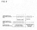
- the packets 5 and 6 reach the reception device before the packets 3 and 4 reach the device, as shown in Fig. 9 .
- An object of the present invention is to provide a transmission system capable of solving a problem that in the 1:1 protection, as a packet loss or a change in the sequence of packets is caused if there is any delay difference between the two lines, line switching for preventive maintenance cannot be performed.
- a transmission system is configured such that a first communication device and a second communication device are connected with each other via a first line and a second line which are used for transmission from the first communication device to the second communication device and a third line which is used for transmission from the second communication device to the first communication device, wherein when the first communication device receives a predetermined message from the third line in a state of transmitting frames of traffic to the first line while performing error-correction coding on the frames, the first communication device switches the line after transmitting a frame of a post-switching message to the first line to thereby transmit the frames of the traffic to the second line while performing error-correction coding on the frames, and the second communication device receives the frames from the first line and the second line and performs error correction on the frames, stores the frames on which error correction has been performed in a first buffer and a second buffer, and when determining that it is necessary to perform line switching from the first line to the second line based on a status of error correction with respect to
- the present invention has the configuration as described above, it is possible to perform line switching for preventive maintenance based on the statues of error correction of received frames without causing a packet loss or a change in the sequence of packets even if there is any delay difference between the first line and the second line. As such, switching can be performed during the time when error correction by the FEC is compensated, so that a frame loss will never be caused by an error, which enables hitless switching.
- a transmission system is configured such that a communication device 810 and a communication device 820 are connected with each other via a line 831 and a line 832 to be used for transmission from the communication device 810 to the communication device 820, and via a line 833 to be used for transmission from the communication device 820 to the communication devices 810.
- the communication device 810 has a function of, when receiving a predetermined message from the line 833 in a state of transmitting the frames of traffic 840 such as user traffic to the line 831 while performing error-correction coding on the frames, switching the line after transmitting a frame of a post-switching message to the line 831, and starting processing to perform error-correction coding on the frames of the traffic 840 and transmitting them to the line 832.
- the communication device 820 has a function of receiving the frames from the line 831 and the line 832 and performing error correction, storing the frames on which the error correction has been performed in buffers 885 and 886, and transmitting the predetermined message to the line 833 when determining that line switching is necessary based on the status of error correction with respect to the frames received from the line 831.
- the communication device 820 also has a function of, when receiving a frame of a post-switching message from the line 831, starting reading of the frames from the buffer 886 after reading all of the frames stored in the buffer 885.
- the transmission system of the present embodiment has the configuration as described above, even if there is a delay difference between the line 831 and the line 832, it is possible to switch the lines from the line 831 to the normal line 832 for preventive maintenance based on the status of error correction of the line 831, without causing a packet loss or a change in the sequence of packets.
- the communication device 810 receives a predetermined message from the line 833 after transmitting, to the line 831, a packet 1, a packet 2, a packet 3, and a packet 4 in this order.
- the communication device 810 switches the line to the line 832 and transmits subsequent packets, namely, a packet 5, a packet 6, a packet 7, and a packet 8 in this order to the line 832.
- the line 832 has a higher speed than the line 831, even if the packets 5 and 6 reach the communication device 820 earlier than the packets 3 and 4, the post-switching message has not reached the communication device 820.
- the packets 5 and 6 remain stored in the buffer 886.
- the packets 3 and 4 reach the communication device 820 later than the packets 5 and 6, the packets 3 and 4 are first stored in the buffer 885.
- the communication device 820 receives the post-switching message via the line 831, the communication device 820 performs line switching.
- the packets 3 and 4 stored in the buffer 885 are first read and output to the outside, and then the packets 5 and 6 stored in the buffer 886 are read.
- the packets 1, 2, 3, 4, 5, 6, 7, and 8 are output in this order from the communication device 820 to the outside, whereby a packet loss or a change in the sequence of the packets will not be caused.
- the communication device 810 may transmit a frame of a pre-switching message to the line 832 before starting transmission of the frames to the line 832.
- the communication device 810 may include a transmission section 850 connected with the lines 831 and 832, a reception section 852 connected with the line 833, and a control section 851.
- the transmission section 850 may include a switching section 871, message processing sections 872 and 873, an FEC frame generation section 874 connected with the line 831, and an FEC frame generation section 875 connected with the line 832. These sections may have the following functions.
- the control section 851 has a function of, when receiving a predetermined message from the line 833, outputting a pre-switching message transmission command signal to the message processing section 873, and after outputting a switching command, signal to the switching section 871, upon completion of switching by the switching section 871, outputting a post-switching message transmission command signal to the message processing section 872.
- the switching section 871 outputs the frames of the traffic to the message processing section 872 in the initial state, and when receiving the switching command signal, outputs the frames of the traffic to the message processing section 873.
- the message processing section 873 transmits a frame of a pre-switching message to the FEC frame generation section 875 based on the pre-switching message transmission command, and then outputs the frames of the traffic, input from the switching section 871, to the FEC frame generation section 875.
- the FEC frame generation section 875 encapsulates the input frames in an FEC frame, and outputs it to the line 832.
- the message processing section 872 outputs the frames of the traffic, input from the switching section 871, to the FEC frame generation section 874, and also outputs a frame of a post-switching message to the FEC frame generation section 874 based on the post-switching message transmission command.
- the FEC frame generation section 874 encapsulates the input frames into an FEC frame, and outputs it to the line 831.
- the communication device 820 may include a reception section 861 connected with the lines 831 and 832, a transmission section 863 connected with the line 833, and a control section 862.
- the reception section 861 may include a frame reproduction section 881 connected with the line 831, a frame reproduction section 882 connected with the line 832, message processing sections 883 and 884, bluffers 885 and 886, an FEC status determination section 888, and a switching section 889. These sections may have the following functions.
- the frame reproduction section 881 has a function of performing error-correction processing of the FEC frame received from the line 831 to reproduce the encapsulated frame and outputting it to the message processing section 883, and also notifying the FEC status determination section 888 of error correction information.
- the error correction information may include information such as presence or absence of occurrence of an FEC error, the size of an FEC error, presence or absence or FEC correction, and the magnitude of FEC correction.
- the frame reproduction section 882 has a function of performing error-correction processing of the FEC frame received from the line 832 to reproduce the encapsulated frame and outputting it to the message processing section 884, and notifying the FEC status determination section 888 of error correction information.
- the message processing section 883 outputs the input frame to the buffer 885 if the input frame is a frame of the traffic, while outputs the input frame to the control section 862 if the input frame is a frame of a post-switching message.
- the message processing section 884 outputs the input frame to the buffer 886 if the input frame is a frame of the traffic, while outputs the input frame to the control section 862 if the input frame is a frame of a pre-switching message.
- the FEC status determination section 888 determines the necessity of line switching from the line 831 to the line 832 based on the notified error correction information, and outputs a switching request signal to the control section 862.
- the control section 862 receives a pre-switching message
- the control section 862 notifies the buffer 886 to start buffering of the traffic.
- the control section 862 receives a post-switching message
- the control section 862 outputs a switching command signal to the switching section 889, and when receiving a switching request signal, transmits the predetermined message to the line 833 by the means of the transmission section 863.
- the predetermined message As the predetermined message, the pre-switching message, the post-switching message, or any other messages may be used.
- a transmission system includes transmission/reception devices 104 and 105, and four lines 200, 201, 202, and 203 connecting the devices 104 and 105.
- Each of the line 200 and the line 201 may be formed of one communication line or one transmission path, or formed of a plurality of communication lines or transmission paths connected via relay devices. Further, in the line 200 and the line 201, a delay time of a packet transmitted from the transmission/reception device 104 until it reaches the transmission/reception device 105 may be almost the same or different.
- Each of the line 202 and the line 203 may be formed of one communication line or one transmission path, or formed of a plurality of communication lines or transmission paths connected via relay devices. Further, in the line 202 and the line 203, a delay time of a packet transmitted from the transmission/reception device 105 until it reaches the transmission/reception device 104 may be almost the same or different.
- the transmission/reception device 104 includes a transmission section 100 which performs error-correction coding on user traffic 108 input from the outside, and transmits it to the transmission/reception device 105 using either the line 200 or the line 201. Further, the transmission/reception device 104 includes a reception section 102 which performs error correction on the user traffic 108 received from the line 202 or the line 203 and outputs it to the outside. Further, the transmission/reception device 104 includes a control section 1 which controls switching of lines used by the transmission section 100 and the reception section 102.
- the transmission/reception device 105 includes a transmission section 103 which performs error-correction coding on the user traffic 108 input from the outside, and transmits it to the transmission/reception device 104 using either the line 202 or the line 203. Further, the transmission/reception device 105 includes a reception section 101 which performs error correction on the user traffic 108 received from the line 200 or the line 201 and outputs it to the outside. Further, the transmission/reception device 105 includes a control section 18 which controls switching of lines used by the transmission section 103 and the reception section 101.
- the transmission system of the present embodiment transmits the user traffic 108 from the transmission/reception device 104 to the transmission/reception device 105 using the line 200, and transmits the user traffic 108 from the transmission/reception device 105 to the transmission/reception device 104 using the line 202.
- the transmission/reception device 105 determines that the state of the line 200 is deteriorated based on the status of error correction of the traffic received via the line 200, in order to request the transmission/reception device 104 to switch the line, the transmission/reception device 105 purposely switches the line, used to transmitting the traffic from the transmission/reception device 105 to the transmission/reception device 104, from the line 202 to the line 203.
- the transmission/reception device 104 When the transmission/reception device 104 detects that the transmission/reception device 104 switches the line used for transmission from the line 202 to the line 203, the transmission/reception device 104 switches the line used for receiving the traffic from the line 202 to the line 203, and also switches the line used for transmitting the traffic from the transmission/reception device 104 to the transmission/reception device 105, from the line 200 to the line 201. Thereby, the user traffic 108 is transmitted from the transmission/reception device 104 to the transmission/reception device 105 with use of the line 201 instead of the line 200 in which the state is deteriorated.
- the transmission/reception device 104 determines that the state of the line 202 is deteriorated based on the status of error correction of the traffic received via the line 202, in order to request the transmission/reception device 105 to switch the line, the transmission/reception device 104 purposely switches the line, used to transmit the traffic from the transmission/reception device 104 to the transmission/reception device 105, from the line 200 to the line 201.
- the transmission/reception device 105 When the transmission/reception device 105 detects that the transmission/reception device 105 switches the line used for transmission from the line 200 to the line 201, the transmission/reception device 105 switches the line used for receiving the traffic from the line 200 to the line 201, and also switches the line used for transmitting the traffic from the transmission/reception device 105 to the transmission/reception device 104, from the line 202 to the line 203. Thereby, the user traffic 108 is transmitted from the transmission/reception device 105 to the transmission/reception device 104 with use of the line 203 instead of the line 202 in which the state is deteriorated.
- reception section 101 the transmission section 103, and the control section 18, constituting the transmission/reception device 105, will be described in detail.
- the reception section 101 includes error detection sections 7 and 8, error correction sections 9 and 10, FEC decapsulating sections 11 and 12, message processing sections 13 and 14, bluffers 15 and 16, a switching section 17, and an FEC status determination section 106. These sections have the following functions, respectively.
- the error detection section 7 detects an FEC error in the FEC traffic received from the line 200, and transmits the FEC traffic to the error correction section 9. Further, the error detection section 7 transmits an FEC error detection signal to the FEC status determination section 106 upon detection of the FEC error.
- the error detection section 8 detects an FEC error in the FEC traffic received from the line 201, and transmits the FEC traffic to the error correction section 10. Further, the error detection section 8 transmits an FEC error detection signal to the FEC status determination section 106 upon detection of the FEC error.
- the error correction section 9 transmits the FEC traffic from the error detection section 7 to the FEC decapsulating section 11. When an FEC error is detected by the error detection section 7, the error correction section 9 corrects the FEC error and transmits it to the FEC decapsulating section 11.
- the error correction section 10 transmits the FEC traffic from the error detection section 8 to the FEC decapsulating section 12. When an FEC error is detected by the error detection section 8, the error correction section 10 corrects the FEC error and transmits it to the FEC decapsulating section 12.
- the FEC decapsulating section 11 decapsulates the FEC traffic from the error correction section 9 into a plurality of Ethernet frames. Then, the FEC decapsulating section 11 transmits the decapsulated Ethernet frames to the message processing section 13.
- the FEC decapsulating section 12 decapsulated the FEC traffic from the error correction section 10 into a plurality of Ethernet frames. Then, the FEC decapsulating section 12 transmits the decapsulated Ethernet frames to the message processing section 14.
- the message processing section 13 separates the user traffic and an event message from the traffic received from the FEC decapsulating section 11, transmits the user traffic to the bluffer 15, transmits the event message to the control section 18.
- the message processing section 14 separates the user traffic and an event message from the traffic received from the FEC decapsulating section 12, transmits the user traffic to the buffer 16, and transmits the event message to the control section 18.
- the buffer 15 is able to temporarily store the user traffic from the message processing section 13, and in accordance with a readout request from the switching section 17, transmits the user traffic to the switching section 17.
- the readout user traffic is deleted from the buffer 15.
- the buffer 16 is able to temporarily store the user traffic from the message processing section 14, and in accordance with a readout request from the switching section 17, transmits the user traffic to the switching section 17.
- the readout user traffic is deleted from the buffer 16.
- the switching section 17 reads the user traffic from the buffer 15 and transmits it to the outside in the initial state where the line 200 is used.
- the switching section 17 switches the buffer from which the user traffic is read, from the buffer 15 to the buffer 16 in accordance with a switching command signal from the control section 18.
- the FEC status determination section 106 records the occurrence times and the number of occurrences of FEC errors regarding the line 200, in accordance with error detection signals of the error detection section 7. Further, the FEC status determination section 106 records the occurrence times and the number of occurrences of FEC errors regarding the line 201, in accordance with error detection signals of the error detection section 8. Then, in the initial state using the line 200, if the FEC status determination section 106 determines that the FEC status of the line 200 is deteriorated to a level requiring line switching such that it has burst and multiple FEC errors have occurred, the FEC status determination section 106 transmits a switching request signal of the line 200 to the control section 18.
- the FEC status determination section 106 records the occurrence time of an FEC error each time the error occurs. As an FEC error is corrected by the error correction section in the latter stage, recording the occurrence time each time an FEC error occurs is equal to recording the correction time each time the FEC error is corrected. Each time the FEC status determination section 106 takes a new record, the FEC status determination section 106 compares the number of records per unit time immediately before, that is, the number of error occurrences (corrections), with a preset threshold.
- the FEC status determination section 106 determines that the possibility of occurrence of an error, which is uncorrectable by FEC, is low in the line 200. On the contrary, if the number of error occurrences (corrections) per unit time exceeds the threshold, the FEC status determination section 106 determines that the line state has been deteriorated such that it is highly likely that an error, which is uncorrectable by FEC, occurs in the line 200, and so transmits a switching request signal in order to perform line switching within the time that all errors can be compensated by FEC.
- the number of error occurrences (corrections), to be compared with the threshold by the FEC status determination section 106, may be the number of FEC error occurrences (corrections) of 1 bit or larger, or the number of FEC error occurrences (corrections) of 2 bits or larger. Further, determination may be performed not only using the number of FEC error occurrences (correction) but also the size of the error (the size of the corrected number of bits). For example, it is possible to obtain an evaluation value which becomes larger as the number of, FEC error occurrences (corrections) per unit time increases and as the number of bits of the error (correction) increases, and compare the evaluation value with a threshold to thereby determine the necessity of switching.
- the transmission section 103 includes a switching section 19, processing sections 20 and 21, and FEC encapsulating sections 22 and 23. These sections have the following functions, respectively.
- the switching section 19 transmits the user traffic 108 to the message processing section 20 in the initial state.
- the switching section 19 switches the transmission direction of the user traffic from the processing section 20 to the message processing section 21 in accordance with a switching command signal from the control section 18.
- the message processing section 20 transmits the user traffic from the switching section 19 to the FEC encapsulating section 22. Further, the message processing section 20 generates an event message in accordance with an event message transmission command signal from the control section 18, combines it with the user traffic, and transmits the result to the FEC encapsulating section 22.
- the message processing section 21 transmits the user traffic from the switching section 19 to the FEC encapsulating section 23. Further, the message processing section 21 generates an event message in accordance with an event message transmission command signal from the control section 18, combines it with the user traffic, and transmits the result to the FEC encapsulating section 23.
- the FEC encapsulating section 22 is able to temporarily store the user traffic from the message processing section 20 in the internal buffer, and encapsulates a plurality of Ethernet frames into one FEC frame.
- the FEC encapsulating section 22 deletes the Ethernet frames, which have been encapsulated, from the internal buffer, and transmits the generated FEC frame to the line 202.
- As a plurality of Ethernet frames are encapsulated in one FEC frame it is not necessary to apply a useless header to each frame, so that the band can be used effectively.
- the FEC encapsulating section 23 is able to temporarily store the user traffic from the processing section 21 in the internal buffer, and encapsulates a plurality of Ethernet frames into one FEC frame.
- the FEC encapsulating section 23 deletes the Ethernet frames, which have been encapsulated, from the internal buffer, and transmits the generated FEC frame to the line 203.
- the control section 18 controls switching of the lines used by the transmission section 103 and the reception section 101, in accordance with the state transition diagram shown in Fig. 2 .
- the control section 18 performs operation in a normal operation mode (state 35 in Fig. 2 ).
- the control section 18 receives a switching request signal of the line 200 from the FEC status determination section 106 because the FEC status determination section 106 has detected deterioration in the FEC status, the control section 18 performs transmission section switching (state 36), and allows the state of the control section 18 to be changed to a post-switching event message reception waiting state (state 37).
- the control section 18 transmits a pre-switching event message transmission command signal to the processing section 21, and transmits a switching command signal to the switching section 19. Then, upon completion of the switching, the control section 18 transmits a post-switching event message transmission command signal to the message processing section 20.
- the control section 18 performs reception section switching (state 38). In the reception section switching, the control section 18 transmits a switching command signal to the switching section 17. Then, the control section 18 returns to the normal operation mode (state 35).
- the control section 18 when the control section 18 receives a post-switching event message from the message processing section 13, the control section 18 performs reception section switching (state 39), and further performs transmission section switching (state 40), and returns to the normal operation mode (state 35).
- the control section 18 transmits a switching command signal to the switching section 17.
- the control section 18 transmits a pre-switching event message transmission command signal to the message processing section 21, and transmits a switching command signal to the switching section 19. Further, upon completion of the switching, the control section 18 transmits a post-switching event message transmission command signal to the processing section 20.
- reception section 102 the transmission section 100, and the control section 1, constituting the transmission/reception device 104, will be described in detail.
- the reception section 102 includes error detection sections 24 and 25, error correction sections 26 and 27, FEC decapsulating sections 28 and 29, message processing sections 30 and 31, bluffers 32 and 33, a switching section 34, and an FEC status determination section 107. These sections have the following functions, respectively.
- the error detection section 24 detects an FEC error in the FEC traffic received from the line 202, and transmits the FEC traffic to the error correction section 26. Further, the error detection section 24 transmits an FEC error detection signal to the FEC status determination section 107 upon detection of the FEC error.
- the error detection section 25 detects an FEC error in the FEC traffic received from the line 203, and transmits the FEC traffic to the error correction section 27. Further, the error detection section 25 transmits an FEC error detection signal to the FEC status determination section 107 upon detection of the FEC error.
- the error correction section 26 transmits the FEC traffic from the error detection section 24, to the FEC decapsulating section 28. Further, when an FEC error is detected by the error detection section 24, the error correction section 26 corrects the FEC error, and transmits the result to the FEC decapsulating section 28.
- the error correction section 27 transmits the FEC traffic from the error detection section 25, to the FEC decapsulating section 29. Further, when an FEC error is detected by the error detection section 25, the error correction section 27 corrects the FEC error, and transmits the result to the FEC decapsulating section 29.
- the FEC decapsulating section 28 decapsulates the FEC traffic from the error correction section 26 into a plurality of Ethernet frames. Then, the FEC decapsulating section 28 transmits the decapsulated Ethernet frames to the message processing section 30.
- the FEC decapsulating section 29 decapsulates the FEC traffic from the error correction section 27 into a plurality of Ethernet frames. Then, the FEC decapsulating section 29 transmits the decapsulated Ethernet frames to the message processing section 31.
- the message processing section 30 separates the user traffic and the event message from the traffic received from the FEC decapsulating section 28, transmits the user traffic to the bluffer 32, and transmits the event message to the control section 1.
- the message processing section 31 separates the user traffic and the event message from the traffic received from the FEC decapsulating section 29, transmits the user traffic to the bluffer 33, and transmits the event message to the control section 1.
- the buffer 32 is able to temporarily store the user traffic from the message processing section 30, and in accordance with a readout request from the switching section 34, transmits the user traffic to the switching section 34.
- the readout user traffic is deleted from the buffer.
- the buffer 33 is able to temporarily store the user traffic from the message processing section 31, and in accordance with a readout request from the switching section 34, transmits the user traffic to the switching section 34.
- the readout user traffic is deleted from the buffer.
- the switching section 34 reads the user traffic from the buffer 32 in the initial state, and transmits it to the outside. Further, the switching section 34 switches the buffer from which the user traffic is read, from the buffer 32 to the buffer 33 in accordance with a switching command signal from the control section 1.
- the FEC status determination section 107 records the occurrence times and the number of occurrences of FEC errors regarding the line 202, in accordance with error detection signals of the error detection section 24. Further, the FEC status determination section 107 records the occurrence times and the number of occurrences of FEC errors regarding the line 203, in accordance with error detection signals of the error detection section 25. Then, in the initial state using the line 202, if the FEC status determination section 107 determines that the FEC status of the line 202 is deteriorated to a level requiring line switching such that it has burst and multiple FEC errors have occurred, the FEC status determination section 107 transmits a switching request signal of the line 202 to the control section 1.
- the transmission section 100 includes a switching section 2, message processing sections 3 and 4, and FEC encapsulating sections 5 and 6. These sections have the following function, respectively.
- the processing section 3 transmits the user traffic from the switching section 2, to the FEC encapsulating section 5. Further, in accordance with an event transmission command signal from the control section 1, the processing section 3 generates an event message, combines it with the user traffic, and transmits the result to the FEC encapsulating section 5.
- the message processing section 4 transmits the user traffic from the switching section 2, to the FEC encapsulating section 6. Further, in accordance with an event message transmission command signal from the control section 1, the message processing section 4 generates an event message, combines it with the user traffic, and transmits the result to the FEC encapsulating section 6.
- the switching section 2 transmits the user traffic 108 to the message processing section 3 in the initial state. Then, the switching section 2 switches the transmission direction of the user traffic 108 from the message processing section 3 to the message processing section 4 in accordance with a switching command signal from the control section 1.
- the FEC encapsulating section 5 is able to temporarily store the user traffic from the message processing section 3 in the internal buffer, and encapsulates a plurality of Ethernet frames into one FEC frame.
- the FEC encapsulating section 5 deletes the encapsulated Ethernet frames from the internal buffer, and transmits the FEC frame to the line 200.
- the FEC encapsulating section 6 is able to temporarily store the user traffic from the message processing section 4 in the internal buffer, and encapsulates a plurality of Ethernet frames into one FEC frame.
- the FEC encapsulating section 6 deletes the encapsulated Ethernet frames from the internal buffer, and transmits the FEC frame to the line 201.
- the control section 1 controls switching of the lines used by the transmission section 100 and the reception section 102 in accordance with the transition diagram shown in Fig. 2 .
- the control section 1 performs operation in a normal operation mode (state 35 in Fig. 2 ).
- the control section 1 receives a switching request signal of the line 202 from the FEC status determination section 106 because the FEC status determination section 106 has detected deterioration in the FEC statues, the control section 1 performs transmission section switching (state 36), and allows the state of the control section to be changed to a post-switching event message reception waiting state (state 37).
- the control section 1 transmits a pre-switching event message transmission command signal to the message processing section 4, and transmits a switching command signal to the switching section 2.
- the control section 1 transmits a post-switching event message transmission command signal to the message processing section 3.
- the control section 1 performs reception section switching (state 38).
- the control section 1 transmits a switching command signal to the switching section 34. Then, the control section 1 returns to the normal operation mode (state 35).
- the control section 1 when the control section 1 receives a post-switching event message from the message processing section 30, the control section 1 performs a reception section switching (state 39), and further performs transmission section switching (state 40), and returns to the normal operation mode (state 35).
- the control section 1 transmits a switching command signal to the switching section 34.
- the control section 1 transmits a pre-switching event message transmission command signal to the message processing section 4, and transmits a switching command signal to the switching section 2. Further, upon completion of the switching, the control section 1 transmits a post-switching event message transmission command signal to the message processing section 3.
- the switching section 2, the switching section 17, the switching section 19, and the switching section 34 can be realized by blocks of switching section in the 1:1 scheme of the Ethernet Linear Protection (ITU-T Recommendation, G.8031).
- the control section 1, the message processing section 3, the message processing section 4, the message processing section 30, the message processing section 31, the control section 18, the message processing section 13, the message processing section 14, the message processing section 20, and the message processing section 21 can be realized by adding functions, based on the similar function blocks in the 1:1 scheme of the Ethernet Linear Protection.
- a pre-switching event message and a post-switching event message generated by the message processing section 3, the message processing section 4, the message processing section 20, and the message processing section 21, can be realized by a VSM (Vendor-Specific OAM Message) defined in the Ethernet OAM (ITU-T Recommendation, Y. 731).
- VSM Vehicle-Specific OAM Message
- a VSM to be used as a pre-switching event message and a VSM to be used as a post-switching event message can be distinguished from each other according to the value set to an operation code (OpCode), for example, in an Ethernet OAM frames.
- OpCode operation code
- Figs. 3 to 6 show sequences of switching a line from the line 200 to the line 201 for preventive maintenance because of the state of the line 200 being deteriorated to a level requiring line switching, during operation in the initial state. First, an outline of the operation will be described.
- the transmission system In the initial state, the transmission system is in the following state.
- the transmission/reception device 104 transmits user traffic to the transmission/reception device 105 via the line 200, and the transmission/reception device 105 receives the traffic via the line 200.
- the switching section 2 transmits the user traffic in the direction of the message processing section 3, and the switching section 17 reads the user traffic from the buffer 15.
- the transmission/reception device 105 transmits user traffic to the transmission/reception device 104 via the line 202, and the transmission/reception device 104 receives the traffic via the line 202.
- the switching section 19 transmits the user traffic in the direction of the message processing section 20, and the switching section 34 reads the user traffic from the buffer 32.
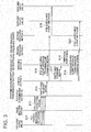
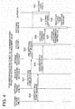
- the transmission/reception device 105 performs a switching sequence shown in Fig. 3 , and transmits a pre-switching event message and a post-switching event message to the transmission/reception device 104. Then, in accordance with the pre-switching event message and the post-switching event message from the transmission/reception device 105, the transmission/reception device 104 performs a switching sequence of the reception section 102 shown in Fig. 4 . Further, the transmission/reception device 104 performs a switching sequence of the transmission section 100 shown in Fig. 5 , in parallel with the switching sequence of the reception section 102, and transmits a pre-switching event message and a post-switching event message to the transmission/reception device 105.
- the transmission/reception device 105 performs a switching sequence of the reception device 101 shown in Fig. 6 , in accordance with the pre-switching event message and the post-switching event message from the transmission/reception device 104.
- the details of the sequences will be described.
- the error detection section 7 when the error detection section 7 receives traffic including an FEC error from the switching source line 200 (step S12 in Fig. 3 ), the error detection section 7 detects the FEC error, and transmits an FEC error detection signal to the FEC status determination section 16 (step S13).
- the FEC status determination section 16 determines that the switching source line 200 is deteriorated to a level requiring switching upon reception of the FEC error detection signal, the FEC status determination section 16 transmits a switching request signal to the control section 18 (step S14).
- the control section 18 transmits a pre-switching event message transmission command signal to the message processing section 21 (step S15).
- the message processing section 21 transmits a pre-switching event message to the switching target line 203 (step S16).
- the control section 18 outputs a switching command signal to the switching section 19 (step S17).
- the switching section 19 performs line switching according to the switching command signal from the control section 18, and changes the transmission direction of the user traffic from the direction of the message processing section 20 to the direction of the message processing section 21 (step S 18).
- control section 18 Upon completion of the switching, the control section 18 transmits a post-switching event message transmission command signal to the message processing section 20 (step S19). Then, the state of the control section 18 is changed to a post-switching event message reception waiting state. Upon reception of the post-switching event message transmission command signal from the control section 18, the message processing section 20 transmits a post-switching event message to the switching source line 202 (step S20).
- the message processing section 31 when the message processing section 31 receives a pre-switching event message from the switching target line 203 (step S21 in Fig. 4 ), the message processing section 31 transmits the pre-switching event message to the control section 1 (step S22). In accordance with the pre-switching event message from the message processing section 31, the control section 1 instructs the buffer 33 to start buffering of the user traffic 108.
- the buffer 33 stores the user traffic flowing subsequent to the pre-switching event message from the message processing section 31 (step S23). It should be noted that the buffer 33 may be adapted to constantly buffer the user traffic received by the message professing section 31.
- the message processing section 30 When the message processing section 30 receives a post-switching event message from the switching source line 202 (step S24), the message processing section 30 transmits the post-switching event message to the control section 1 (step S25).
- the control section 1 When the post-switching event message from the message processing section 30 is provided to the control section 1, as the control section 1 has received the post-switching event message in the normal operation mode, the control section 1 transmits a switching command signal to the switching section 34 in order to perform reception section switching (step S26). Further, upon reception of the post-switching event message from the message processing section 30, the control section 1 performs switching of the transmission section 100 in accordance with the switching sequence shown in Fig. 5 described below (step S29).
- the switching execution sequence of the transmission section 100 and the switching execution sequence of the reception section 102 are performed in parallel. It should be noted that upon reception of the pre-switching event message from the processing section 31, the control section 1 may perform switching of the transmission section 100 in accordance with the switching sequence shown in Fig. 5 described below.
- the switching section 34 When the switching section 34 receives the switching command signal from the control section 1, the switching section 34 performs line switching to switch the buffer, from which the user traffic is read, from the buffer 32 to the buffer 33 (step S27). Upon completion of the switching, the switching section 34 reads the user traffic stored in the buffer 33, and transmits it to the outside (step S28). The buffer 33 deletes the readout user traffic.
- the control section 1 performs switching of the reception section 102 (step S30), and then transmits a pre-switching event message transmission command signal to the message processing section 4 (step S31).
- the message processing section 4 receives the pre-switching event message transmission command signal from the control section 1, the message processing section 4 transmits a pre-switching event message to the switching target line 201 (step S32).
- the control section 1 transmits a switching command signal to the switching section 2 (step S33).
- the switching section 2 receives the switching command signal from the control section 1, the switching section 2 performs line switching to switch the transmission direction of the user traffic from the direction of the message processing section 3 to the direction of the message processing section 4 (step S34).
- the control section 1 Upon completion of the switching, the control section 1 transmits a post-switching event message transmission command signal to the message processing section 3 (step S35). Then, the control section 1 returns to the normal operation mode.
- the message processing section 3 receives the post-switching event message transmission command signal from the control section 1, the message processing section 3 transmits a post-switching event message to the switching source line 200 (step S36).
- Fig. 1 when the message processing section 14 receives a pre-switching event message from the switching target line 201 (step S37 in Fig. 6 ), the message processing section 14 transmits a pre-switching event message to the control section 18 (step S38).
- the control section 18 instructs the buffer 16 to start buffering of the user traffic in accordance with the pre-switching event message from the message processing section 14.
- the buffer 16 stores the user traffic, flowing subsequent to the pre-switching event message from the message processing section 14, in the buffer (step S39).
- the message processing section 13 When the message processing section 13 receives a post-switching event message from the switching source line 200 (step S40), the message processing section 13 transmits a post-switching event message to the control section 18 (step S41).
- the control section 18 transmits a switching command signal to the switching section 17 in order to perform reception section switching (step S42).
- the switching section 16 When the switching command signal from the control section 18 is provided to the switching section 17, the switching section 16 performs line switching to switch the buffer, from which the user traffic is read, from the buffer 15 to the buffer 16 (step S43).
- the switching section 17 Upon completion of the switching, the switching section 17 reads the user traffic stored in the buffer 16, and transmits it to the outside (step S44).
- the buffer 16 deletes the readout user traffic.
- the transmission/reception device 104 and the transmission/reception device 105 have performed switching of the transmission sections and the reception sections respectively, triggered by the deterioration in the state of the line 200, to thereby perform bidirectional switching from the switching source line 200 and the switching source line 202 to the switching target line 20 and the switching target line 203.
- the state of the transmission/reception device 105 is changed in the sequence of a normal operation mode (state 35), transmission section switching (state 36), post-switching event message reception waiting (state 37), reception section switching (state 38), and a normal operation mode (state 35), in accordance with the state transmission diagram of Fig. 2 .
- the state of the transmission/reception device 104 is changed in the sequence of a normal operation mode (state 35), reception section switching (state 39), transmission section switching (state 40), and a normal operation mode (state 35), in accordance with the transmission diagram of Fig. 2 .
- the transmission/reception device 104 and the transmission/reception device 105 perform switching of the transmission sections and the reception sections respectively, triggered by the deterioration in the state of the line 202, to thereby perform bidirectional switching from the switching source line 200 and the switching source line 202 to the switching target line 201 and the switching target line 203.
- the transmission/reception device 104 first performs switching of the transmission section 100, then the transmission/reception device 105 performs switching of the reception section 101 and the transmission section 103, and finally the transmission/reception device 104 switches the reception section 102.
- the state of the transmission/reception device 104 is changed in the sequence of a normal operation mode (state 35), transmission section switching (state 36), post-switching event message reception waiting (state 37), reception section switching (state 38), and a normal operation mode (state 35), in accordance with the state transition diagram of Fig. 2 .
- the state of the transmission/reception device 105 is changed in the sequence of a normal operation mode (state 35), reception section switching (state 39), transmission section switching (state 40), and a normal operation mode (state 35), in accordance with the state transition diagram of Fig. 2 .
- the transmission/reception device 104 and the transmission/reception device 105 perform switching of the transmission sections and the reception sections respectively, triggered by the deterioration in the states of the lines 200 and 202, to thereby perform bidirectional switching from the switching source line 200 and the switching source line 202 to the switching target line 201 and the switching target line 203.
- the states of the transmission/reception device 104 and the transmission/reception device 105 are changed in the sequence of a normal operation mode (state 35), transmission section switching (state 36), post-switching event message reception waiting (state 37), reception section switching (state 38), and a normal operation mode (state 35), in accordance with the state transition diagram of Fig. 2 .
- the present embodiment even if there is a delay difference between the switching source lines 200 and 202 and the switching target lines 201 and 203, it is possible to perform line switching for preventive maintenance based on the status of error correction of the lines, without causing a packet loss or a change in the sequence of packets.
- the transmission section 100 switches the line to the line 201 and transmits subsequent packets, namely, a packet 5, a packet 6, a packet 7, and a packet 8, of the user traffic to the line 201 in this order.
- the transmission section 100 transmits a pre-switching event message to the line 201 before transmitting the packet 5, and transmits a post-switching event message to the line 200 after transmitting the packet 4.
- the line 201 has a higher speed than the line 200, even if the packets 5 and 6 reach the reception section 101 earlier than the packets 3 and 4, the post-switching event message has not reached the reception section 101. As such, the packets 5 and 6 remain stored in the buffer 16.
- the packets 3 and 4 reach the reception section 101 after the packets 5 and 6, the packets 3 and 4 are first stored in the buffer 15. Then, when the reception section 101 receives the post-switching event message via the line 200, the reception section 101 performs line switching. Thereby, the packets 3 and 4 stored in the buffer 15 are first read and output to the outside, and then the packets 5 and 6 stored in the buffer 16 are read. As a result, the packets 1, 2, 3, 4, 5, 6, 7, and 8 are output in this order from the switching section 17 to the outside, whereby a packet loss or a change in the sequence of the packets will not be caused.
- the control section 18 transmits a switching notification message transmission command signal to the message processing section 20.
- the message processing section 20 combines a switching notification message using VSM of the Ethernet OAM with the user traffic, and transmits the result to the transmission/reception device 104 via the switching source line 202.
- the message processing section 30 separates the traffic into the user traffic and the switching notification message in accordance with the switching notification message from the switching source line 202, and transmits a switching command signal to the control section 1.
- the control section 1 receives the switching command signal, the control section 1 performs switching of the transmission section 100 in the same manner as that described in the first exemplary embodiment. Thereby, switching of the reception section 101 is performed subsequently in the same manner as that described in the second exemplary embodiment.
- line switching in a single direction can be performed, which is triggered by deterioration in the line state of one of the switching source lines 200 and 202.
- a fourth exemplary embodiment of the present invention while the basic configuration thereof is the same as that of the first to third exemplary embodiments, another effort is made to an event message.
- Fig. 7 shows the configuration of the fourth exemplary embodiment.
- the message processing section makes copies of a post-switching event message when transmitting the post-switching event message, and transmits a plurality of copies of the post-switching event message continuously.
- the present embodiment can achieve an advantageous effect that the line switching processing can be operated normally as long as at least one copy of the post-switching event message is normal.
- the present invention is also applicable to a communication device implementing both 1:1 protection and 1+1 protection.
- a pre-switching message as an instruction to start buffering of a switching target line in the 1+1 protection, it is possible to prevent generation of frame overlap when switching a line in the 1+1 protection.
- the present invention is applicable to line switching for preventive maintenance, and in particular, applicable to switching between lines having some delay difference.
Landscapes
- Engineering & Computer Science (AREA)
- Computer Networks & Wireless Communication (AREA)
- Signal Processing (AREA)
- Computer Security & Cryptography (AREA)
- Quality & Reliability (AREA)
- Detection And Prevention Of Errors In Transmission (AREA)
- Maintenance And Management Of Digital Transmission (AREA)
- Data Exchanges In Wide-Area Networks (AREA)
Abstract
Description
- The present invention relates to a transmission system in which communication devices are connected via a plurality of lines in order to improve the reliability of communication, and in particular, to a technique of switching lines to be used for communication.
- A 1:1 protection scheme is standardized by ITU-T (International Telecommunication Union) (ITU-T Recommendation G.8031). In this scheme, a transmission device and a reception device are connected via two lines in order to improve the reliability of communication, and in the initial state, communication is performed using one of the lines, while at the time of maintenance work or failure, communication is performed using the other line. In particular, in the 1:1 protection standardized by the ITU-T, a line can be switched to another line by the unit of VLAN traffic based on a switching request by a user.
- In the 1:1 protection standardized by the ITU-T Recommendation G.8031, the line switching sections of a transmission device and a reception device are synchronized with each other to switch a line. Meanwhile, another scheme is also proposed, in which a reception device regularly receives frames from the both lines, and 1:1 protection is realized by only switching the line of the transmission device side (see
Patent Document 1, for example). - On the other hand, regarding a 1+1 protection scheme rather than the 1:1 protection,
Patent Document 2 describes a technique of performing line switching for preventive maintenance based on the status of error correction of a line. Specifically, the transmission side inputs, to a path, a multiframe pattern for detecting a transmission delay difference between the active system and the standby system at the reception side to generate a multiplexed SONET/SDH frame, encapsulates the SONET/SDH frame in a frame for FEC (Forward Error correction), and transmits the result to both the active system line and the standby system line. The reception side includes, in each of the active system and the standby system, an FEC function frame reproduction section which extracts the SONET/SDH frame from the received FEC frame, performs error-correction processing by the FEC function, and then transfers error correction information; a demultiplexing section which terminates the path from the generated SONET/SDH frame and establishes synchronization of the multiframe added at the transmission side; a B3 error detection section which compares, with respect to the frame from the demultiplexing section, a parity operation result for each path with the B3 byte of the next path to detect presence or absence of a B3 error; and a B3 error in which data from the B3 error detection section is written in order to offset a transmission path delay difference between the active system and the standby system and which is read at the timing extracted from multiframe synchronization. Further, the reception side includes a switching control section which switches, between the active system the standby system, data from a delay memory based on the B3 error the error correction information. - It should be noted that in this description, a frame of the Ethernet (registered trademark) is simply called as a frame or a packet.
-
- Patent-Document 1:
JP 10-145374A - Patent Document 2:
JP 2005-260820 A - In the 1:1 protection standardized by the ITU-T, if the switching target line is a high-speed line having a smaller delay quantity compared with that of the switching source line, there is a problem that a packet loss is caused when switching lines. For example, when a transmission device transmits a
packet 1, apacket 2, apacket 3, and apacket 4 in this order to the switching source line, and then transmits subsequent packets, namely, apacket 5, apacket 6, apacket 7, and apacket 8, in this order to the switching target line, if the switching target line is a higher-speed line compared with the switching source line, thepackets packets Fig. 9 . As such, if line switching is performed immediately after thepacket 2 is received from the switching source line, thepackets packet 4 is received from the switching source line, thepackets - On the other hand, in the scheme described in Patent-
Document 1, as the reception device is able to receive not only thepackets 1 to 4 but also thepackets 5 to 8, a packet loss can be prevented. However, a state where thepackets packets - Further, although switching lines for preventive maintenance based on the status of error correction of the received frames is performed in the 1+1 protection scheme as described in
Patent Document 2, a case of applying such a technique to the 1:1 protection scheme has not been found. The grounds are as follows: as the status of error correction of the received frames is only detected by the reception side, it is considered difficult to apply the technique to the 1:1 protection in which path switching is performed at the transmission side; and as a packet loss or a change in the sequence of packets is caused if there is any delay difference between the two lines in the 1:1 protection as described above, preventive maintenance cannot be realized. - An object of the present invention is to provide a transmission system capable of solving a problem that in the 1:1 protection, as a packet loss or a change in the sequence of packets is caused if there is any delay difference between the two lines, line switching for preventive maintenance cannot be performed.
- A transmission system, according to an aspect of the present invention, is configured such that a first communication device and a second communication device are connected with each other via a first line and a second line which are used for transmission from the first communication device to the second communication device and a third line which is used for transmission from the second communication device to the first communication device, wherein
when the first communication device receives a predetermined message from the third line in a state of transmitting frames of traffic to the first line while performing error-correction coding on the frames, the first communication device switches the line after transmitting a frame of a post-switching message to the first line to thereby transmit the frames of the traffic to the second line while performing error-correction coding on the frames, and
the second communication device receives the frames from the first line and the second line and performs error correction on the frames, stores the frames on which error correction has been performed in a first buffer and a second buffer, and when determining that it is necessary to perform line switching from the first line to the second line based on a status of error correction with respect to the frames received from the first line, transmits the predetermined message to the third line, and when receiving the frame of the post-switching message from the first line, starts reading of the frames from the second buffer after reading all of the frames stored in the first buffer. - As the present invention has the configuration as described above, it is possible to perform line switching for preventive maintenance based on the statues of error correction of received frames without causing a packet loss or a change in the sequence of packets even if there is any delay difference between the first line and the second line. As such, switching can be performed during the time when error correction by the FEC is compensated, so that a frame loss will never be caused by an error, which enables hitless switching.
-
-
Fig. 1 is a block diagram showing a second exemplary embodiment of the present invention. -
Fig. 2 is a state transition diagram of a control section of a transmission/reception device according to the second exemplary embodiment of the present invention. -
Fig. 3 is a chart showing a transmission section switching sequence of one transmission/reception device according to the second exemplary embodiment of the present invention. -
Fig. 4 is a chart showing a reception section switching sequence of another transmission/reception device according to the second exemplary embodiment of the present invention. -
Fig. 5 is a chart showing a transmission section switching sequence of the other transmission/reception device according to the second exemplary embodiment of the present invention. -
Fig. 6 is a chart showing a reception section switching sequence of the one transmission/reception device according to the second exemplary embodiment of the present invention. -
Fig. 7 is a block diagram showing the main part of another exemplary embodiment of the present invention. -
Fig. 8 is a block diagram showing a first exemplary embodiment of the present invention. -
Fig. 9 is illustration showing the problem to be solved by the present invention. - Next, exemplary embodiments of the present invention will be described in detail with reference to the drawings.
- Referring to
Fig. 8 , a transmission system according to a first exemplary embodiment of the present invention is configured such that acommunication device 810 and acommunication device 820 are connected with each other via aline 831 and aline 832 to be used for transmission from thecommunication device 810 to thecommunication device 820, and via aline 833 to be used for transmission from thecommunication device 820 to thecommunication devices 810. - The
communication device 810 has a function of, when receiving a predetermined message from theline 833 in a state of transmitting the frames oftraffic 840 such as user traffic to theline 831 while performing error-correction coding on the frames, switching the line after transmitting a frame of a post-switching message to theline 831, and starting processing to perform error-correction coding on the frames of thetraffic 840 and transmitting them to theline 832. - The
communication device 820 has a function of receiving the frames from theline 831 and theline 832 and performing error correction, storing the frames on which the error correction has been performed inbuffers line 833 when determining that line switching is necessary based on the status of error correction with respect to the frames received from theline 831. Thecommunication device 820 also has a function of, when receiving a frame of a post-switching message from theline 831, starting reading of the frames from thebuffer 886 after reading all of the frames stored in thebuffer 885. - As the transmission system of the present embodiment has the configuration as described above, even if there is a delay difference between the
line 831 and theline 832, it is possible to switch the lines from theline 831 to thenormal line 832 for preventive maintenance based on the status of error correction of theline 831, without causing a packet loss or a change in the sequence of packets. - For example, it is assumed that the
communication device 810 receives a predetermined message from theline 833 after transmitting, to theline 831, apacket 1, apacket 2, apacket 3, and apacket 4 in this order. In this case, after transmitting a post-switching message to theline 831, thecommunication device 810 switches the line to theline 832 and transmits subsequent packets, namely, apacket 5, apacket 6, apacket 7, and apacket 8 in this order to theline 832. As theline 832 has a higher speed than theline 831, even if thepackets communication device 820 earlier than thepackets communication device 820. As such, thepackets buffer 886. When thepackets communication device 820 later than thepackets packets buffer 885. Then, when thecommunication device 820 receives the post-switching message via theline 831, thecommunication device 820 performs line switching. Thereby, thepackets buffer 885 are first read and output to the outside, and then thepackets buffer 886 are read. As a result, thepackets communication device 820 to the outside, whereby a packet loss or a change in the sequence of the packets will not be caused. - While the basic configuration of the present embodiment is as described above, various additions and changes can be made. For example, the
communication device 810 may transmit a frame of a pre-switching message to theline 832 before starting transmission of the frames to theline 832. - Further, as shown in
Fig. 8 , thecommunication device 810 may include atransmission section 850 connected with thelines reception section 852 connected with theline 833, and acontrol section 851. Further, thetransmission section 850 may include aswitching section 871,message processing sections frame generation section 874 connected with theline 831, and an FECframe generation section 875 connected with theline 832. These sections may have the following functions. - The
control section 851 has a function of, when receiving a predetermined message from theline 833, outputting a pre-switching message transmission command signal to themessage processing section 873, and after outputting a switching command, signal to theswitching section 871, upon completion of switching by theswitching section 871, outputting a post-switching message transmission command signal to themessage processing section 872. - The
switching section 871 outputs the frames of the traffic to themessage processing section 872 in the initial state, and when receiving the switching command signal, outputs the frames of the traffic to themessage processing section 873. Themessage processing section 873 transmits a frame of a pre-switching message to the FECframe generation section 875 based on the pre-switching message transmission command, and then outputs the frames of the traffic, input from theswitching section 871, to the FECframe generation section 875. The FECframe generation section 875 encapsulates the input frames in an FEC frame, and outputs it to theline 832. - The
message processing section 872 outputs the frames of the traffic, input from theswitching section 871, to the FECframe generation section 874, and also outputs a frame of a post-switching message to the FECframe generation section 874 based on the post-switching message transmission command. The FECframe generation section 874 encapsulates the input frames into an FEC frame, and outputs it to theline 831. - Further, the
communication device 820 may include areception section 861 connected with thelines transmission section 863 connected with theline 833, and acontrol section 862. Thereception section 861 may include aframe reproduction section 881 connected with theline 831, aframe reproduction section 882 connected with theline 832,message processing sections 883 and 884,bluffers status determination section 888, and aswitching section 889. These sections may have the following functions. - The
frame reproduction section 881 has a function of performing error-correction processing of the FEC frame received from theline 831 to reproduce the encapsulated frame and outputting it to themessage processing section 883, and also notifying the FECstatus determination section 888 of error correction information. The error correction information may include information such as presence or absence of occurrence of an FEC error, the size of an FEC error, presence or absence or FEC correction, and the magnitude of FEC correction. Theframe reproduction section 882 has a function of performing error-correction processing of the FEC frame received from theline 832 to reproduce the encapsulated frame and outputting it to the message processing section 884, and notifying the FECstatus determination section 888 of error correction information. - The
message processing section 883 outputs the input frame to thebuffer 885 if the input frame is a frame of the traffic, while outputs the input frame to thecontrol section 862 if the input frame is a frame of a post-switching message. The message processing section 884 outputs the input frame to thebuffer 886 if the input frame is a frame of the traffic, while outputs the input frame to thecontrol section 862 if the input frame is a frame of a pre-switching message. - The FEC
status determination section 888 determines the necessity of line switching from theline 831 to theline 832 based on the notified error correction information, and outputs a switching request signal to thecontrol section 862. When thecontrol section 862 receives a pre-switching message, thecontrol section 862 notifies thebuffer 886 to start buffering of the traffic. Further, when thecontrol section 862 receives a post-switching message, thecontrol section 862 outputs a switching command signal to theswitching section 889, and when receiving a switching request signal, transmits the predetermined message to theline 833 by the means of thetransmission section 863. - As the predetermined message, the pre-switching message, the post-switching message, or any other messages may be used.
- Referring to
Fig 1 , a transmission system according to a second exemplary embodiment of the present invention includes transmission/reception devices lines devices - Each of the
line 200 and theline 201 may be formed of one communication line or one transmission path, or formed of a plurality of communication lines or transmission paths connected via relay devices. Further, in theline 200 and theline 201, a delay time of a packet transmitted from the transmission/reception device 104 until it reaches the transmission/reception device 105 may be almost the same or different. - Each of the
line 202 and theline 203 may be formed of one communication line or one transmission path, or formed of a plurality of communication lines or transmission paths connected via relay devices. Further, in theline 202 and theline 203, a delay time of a packet transmitted from the transmission/reception device 105 until it reaches the transmission/reception device 104 may be almost the same or different. - The transmission/
reception device 104 includes atransmission section 100 which performs error-correction coding onuser traffic 108 input from the outside, and transmits it to the transmission/reception device 105 using either theline 200 or theline 201. Further, the transmission/reception device 104 includes areception section 102 which performs error correction on theuser traffic 108 received from theline 202 or theline 203 and outputs it to the outside. Further, the transmission/reception device 104 includes acontrol section 1 which controls switching of lines used by thetransmission section 100 and thereception section 102. - The transmission/
reception device 105 includes atransmission section 103 which performs error-correction coding on theuser traffic 108 input from the outside, and transmits it to the transmission/reception device 104 using either theline 202 or theline 203. Further, the transmission/reception device 105 includes areception section 101 which performs error correction on theuser traffic 108 received from theline 200 or theline 201 and outputs it to the outside. Further, the transmission/reception device 105 includes acontrol section 18 which controls switching of lines used by thetransmission section 103 and thereception section 101. - In the initial state, the transmission system of the present embodiment transmits the
user traffic 108 from the transmission/reception device 104 to the transmission/reception device 105 using theline 200, and transmits theuser traffic 108 from the transmission/reception device 105 to the transmission/reception device 104 using theline 202. When the transmission/reception device 105 determines that the state of theline 200 is deteriorated based on the status of error correction of the traffic received via theline 200, in order to request the transmission/reception device 104 to switch the line, the transmission/reception device 105 purposely switches the line, used to transmitting the traffic from the transmission/reception device 105 to the transmission/reception device 104, from theline 202 to theline 203. When the transmission/reception device 104 detects that the transmission/reception device 104 switches the line used for transmission from theline 202 to theline 203, the transmission/reception device 104 switches the line used for receiving the traffic from theline 202 to theline 203, and also switches the line used for transmitting the traffic from the transmission/reception device 104 to the transmission/reception device 105, from theline 200 to theline 201. Thereby, theuser traffic 108 is transmitted from the transmission/reception device 104 to the transmission/reception device 105 with use of theline 201 instead of theline 200 in which the state is deteriorated. - Further, in the initial state, when the transmission/
reception device 104 determines that the state of theline 202 is deteriorated based on the status of error correction of the traffic received via theline 202, in order to request the transmission/reception device 105 to switch the line, the transmission/reception device 104 purposely switches the line, used to transmit the traffic from the transmission/reception device 104 to the transmission/reception device 105, from theline 200 to theline 201. When the transmission/reception device 105 detects that the transmission/reception device 105 switches the line used for transmission from theline 200 to theline 201, the transmission/reception device 105 switches the line used for receiving the traffic from theline 200 to theline 201, and also switches the line used for transmitting the traffic from the transmission/reception device 105 to the transmission/reception device 104, from theline 202 to theline 203. Thereby, theuser traffic 108 is transmitted from the transmission/reception device 105 to the transmission/reception device 104 with use of theline 203 instead of theline 202 in which the state is deteriorated. - Next, the
reception section 101, thetransmission section 103, and thecontrol section 18, constituting the transmission/reception device 105, will be described in detail. - The
reception section 101 includeserror detection sections error correction sections FEC decapsulating sections message processing sections bluffers switching section 17, and an FECstatus determination section 106. These sections have the following functions, respectively. - The
error detection section 7 detects an FEC error in the FEC traffic received from theline 200, and transmits the FEC traffic to theerror correction section 9. Further, theerror detection section 7 transmits an FEC error detection signal to the FECstatus determination section 106 upon detection of the FEC error. - The
error detection section 8 detects an FEC error in the FEC traffic received from theline 201, and transmits the FEC traffic to theerror correction section 10. Further, theerror detection section 8 transmits an FEC error detection signal to the FECstatus determination section 106 upon detection of the FEC error. - The
error correction section 9 transmits the FEC traffic from theerror detection section 7 to theFEC decapsulating section 11. When an FEC error is detected by theerror detection section 7, theerror correction section 9 corrects the FEC error and transmits it to theFEC decapsulating section 11. - The
error correction section 10 transmits the FEC traffic from theerror detection section 8 to theFEC decapsulating section 12. When an FEC error is detected by theerror detection section 8, theerror correction section 10 corrects the FEC error and transmits it to theFEC decapsulating section 12. - The
FEC decapsulating section 11 decapsulates the FEC traffic from theerror correction section 9 into a plurality of Ethernet frames. Then, theFEC decapsulating section 11 transmits the decapsulated Ethernet frames to themessage processing section 13. - The
FEC decapsulating section 12 decapsulated the FEC traffic from theerror correction section 10 into a plurality of Ethernet frames. Then, theFEC decapsulating section 12 transmits the decapsulated Ethernet frames to themessage processing section 14. - The
message processing section 13 separates the user traffic and an event message from the traffic received from theFEC decapsulating section 11, transmits the user traffic to the bluffer 15, transmits the event message to thecontrol section 18. - The
message processing section 14 separates the user traffic and an event message from the traffic received from theFEC decapsulating section 12, transmits the user traffic to thebuffer 16, and transmits the event message to thecontrol section 18. - The
buffer 15 is able to temporarily store the user traffic from themessage processing section 13, and in accordance with a readout request from the switchingsection 17, transmits the user traffic to theswitching section 17. The readout user traffic is deleted from thebuffer 15. - The
buffer 16 is able to temporarily store the user traffic from themessage processing section 14, and in accordance with a readout request from the switchingsection 17, transmits the user traffic to theswitching section 17. The readout user traffic is deleted from thebuffer 16. - The switching
section 17 reads the user traffic from thebuffer 15 and transmits it to the outside in the initial state where theline 200 is used. The switchingsection 17 switches the buffer from which the user traffic is read, from thebuffer 15 to thebuffer 16 in accordance with a switching command signal from thecontrol section 18. - The FEC
status determination section 106 records the occurrence times and the number of occurrences of FEC errors regarding theline 200, in accordance with error detection signals of theerror detection section 7. Further, the FECstatus determination section 106 records the occurrence times and the number of occurrences of FEC errors regarding theline 201, in accordance with error detection signals of theerror detection section 8. Then, in the initial state using theline 200, if the FECstatus determination section 106 determines that the FEC status of theline 200 is deteriorated to a level requiring line switching such that it has burst and multiple FEC errors have occurred, the FECstatus determination section 106 transmits a switching request signal of theline 200 to thecontrol section 18. - The condition that the FEC
status determination section 106 transmits a switching request signal will be described in more detail (this also applies to the FECstatus determination section 107 describe below). For example, the FECstatus determination section 106 records the occurrence time of an FEC error each time the error occurs. As an FEC error is corrected by the error correction section in the latter stage, recording the occurrence time each time an FEC error occurs is equal to recording the correction time each time the FEC error is corrected. Each time the FECstatus determination section 106 takes a new record, the FECstatus determination section 106 compares the number of records per unit time immediately before, that is, the number of error occurrences (corrections), with a preset threshold. Then, if the number of error occurrences (corrections) per unit time does not exceed the threshold, the FECstatus determination section 106 determines that the possibility of occurrence of an error, which is uncorrectable by FEC, is low in theline 200. On the contrary, if the number of error occurrences (corrections) per unit time exceeds the threshold, the FECstatus determination section 106 determines that the line state has been deteriorated such that it is highly likely that an error, which is uncorrectable by FEC, occurs in theline 200, and so transmits a switching request signal in order to perform line switching within the time that all errors can be compensated by FEC. - The number of error occurrences (corrections), to be compared with the threshold by the FEC
status determination section 106, may be the number of FEC error occurrences (corrections) of 1 bit or larger, or the number of FEC error occurrences (corrections) of 2 bits or larger. Further, determination may be performed not only using the number of FEC error occurrences (correction) but also the size of the error (the size of the corrected number of bits). For example, it is possible to obtain an evaluation value which becomes larger as the number of, FEC error occurrences (corrections) per unit time increases and as the number of bits of the error (correction) increases, and compare the evaluation value with a threshold to thereby determine the necessity of switching. - The
transmission section 103 includes aswitching section 19,processing sections FEC encapsulating sections - The switching
section 19 transmits theuser traffic 108 to themessage processing section 20 in the initial state. The switchingsection 19 switches the transmission direction of the user traffic from theprocessing section 20 to themessage processing section 21 in accordance with a switching command signal from thecontrol section 18. - The
message processing section 20 transmits the user traffic from the switchingsection 19 to theFEC encapsulating section 22. Further, themessage processing section 20 generates an event message in accordance with an event message transmission command signal from thecontrol section 18, combines it with the user traffic, and transmits the result to theFEC encapsulating section 22. - The
message processing section 21 transmits the user traffic from the switchingsection 19 to theFEC encapsulating section 23. Further, themessage processing section 21 generates an event message in accordance with an event message transmission command signal from thecontrol section 18, combines it with the user traffic, and transmits the result to theFEC encapsulating section 23. - The
FEC encapsulating section 22 is able to temporarily store the user traffic from themessage processing section 20 in the internal buffer, and encapsulates a plurality of Ethernet frames into one FEC frame. TheFEC encapsulating section 22 deletes the Ethernet frames, which have been encapsulated, from the internal buffer, and transmits the generated FEC frame to theline 202. In the present embodiment, as a plurality of Ethernet frames are encapsulated in one FEC frame, it is not necessary to apply a useless header to each frame, so that the band can be used effectively. - The
FEC encapsulating section 23 is able to temporarily store the user traffic from theprocessing section 21 in the internal buffer, and encapsulates a plurality of Ethernet frames into one FEC frame. TheFEC encapsulating section 23 deletes the Ethernet frames, which have been encapsulated, from the internal buffer, and transmits the generated FEC frame to theline 203. - The
control section 18 controls switching of the lines used by thetransmission section 103 and thereception section 101, in accordance with the state transition diagram shown inFig. 2 . In the initial state, thecontrol section 18 performs operation in a normal operation mode (state 35 inFig. 2 ). In the normal operation mode (state 35), when thecontrol section 18 receives a switching request signal of theline 200 from the FECstatus determination section 106 because the FECstatus determination section 106 has detected deterioration in the FEC status, thecontrol section 18 performs transmission section switching (state 36), and allows the state of thecontrol section 18 to be changed to a post-switching event message reception waiting state (state 37). In the transmission section switching in thestate 36, thecontrol section 18 transmits a pre-switching event message transmission command signal to theprocessing section 21, and transmits a switching command signal to theswitching section 19. Then, upon completion of the switching, thecontrol section 18 transmits a post-switching event message transmission command signal to themessage processing section 20. In the post-switching event messagereception waiting state 37, when thecontrol section 18 is notified from themessage processing section 13 that the post-switching event message has been received, thecontrol section 18 performs reception section switching (state 38). In the reception section switching, thecontrol section 18 transmits a switching command signal to theswitching section 17. Then, thecontrol section 18 returns to the normal operation mode (state 35). - On the other hand, in the normal operation mode (state 35), when the
control section 18 receives a post-switching event message from themessage processing section 13, thecontrol section 18 performs reception section switching (state 39), and further performs transmission section switching (state 40), and returns to the normal operation mode (state 35). In the reception section switching in thestate 39, thecontrol section 18 transmits a switching command signal to theswitching section 17. Further, in the transmission section switching in thestate 40, thecontrol section 18 transmits a pre-switching event message transmission command signal to themessage processing section 21, and transmits a switching command signal to theswitching section 19. Further, upon completion of the switching, thecontrol section 18 transmits a post-switching event message transmission command signal to theprocessing section 20. - Next, the
reception section 102, thetransmission section 100, and thecontrol section 1, constituting the transmission/reception device 104, will be described in detail. - The
reception section 102 includeserror detection sections error correction sections FEC decapsulating sections message processing sections bluffers switching section 34, and an FECstatus determination section 107. These sections have the following functions, respectively. - The
error detection section 24 detects an FEC error in the FEC traffic received from theline 202, and transmits the FEC traffic to theerror correction section 26. Further, theerror detection section 24 transmits an FEC error detection signal to the FECstatus determination section 107 upon detection of the FEC error. - The
error detection section 25 detects an FEC error in the FEC traffic received from theline 203, and transmits the FEC traffic to theerror correction section 27. Further, theerror detection section 25 transmits an FEC error detection signal to the FECstatus determination section 107 upon detection of the FEC error. - The
error correction section 26 transmits the FEC traffic from theerror detection section 24, to theFEC decapsulating section 28. Further, when an FEC error is detected by theerror detection section 24, theerror correction section 26 corrects the FEC error, and transmits the result to theFEC decapsulating section 28. - The
error correction section 27 transmits the FEC traffic from theerror detection section 25, to theFEC decapsulating section 29. Further, when an FEC error is detected by theerror detection section 25, theerror correction section 27 corrects the FEC error, and transmits the result to theFEC decapsulating section 29. - The
FEC decapsulating section 28 decapsulates the FEC traffic from theerror correction section 26 into a plurality of Ethernet frames. Then, theFEC decapsulating section 28 transmits the decapsulated Ethernet frames to themessage processing section 30. - The
FEC decapsulating section 29 decapsulates the FEC traffic from theerror correction section 27 into a plurality of Ethernet frames. Then, theFEC decapsulating section 29 transmits the decapsulated Ethernet frames to themessage processing section 31. - The
message processing section 30 separates the user traffic and the event message from the traffic received from theFEC decapsulating section 28, transmits the user traffic to the bluffer 32, and transmits the event message to thecontrol section 1. - The
message processing section 31 separates the user traffic and the event message from the traffic received from theFEC decapsulating section 29, transmits the user traffic to the bluffer 33, and transmits the event message to thecontrol section 1. - The
buffer 32 is able to temporarily store the user traffic from themessage processing section 30, and in accordance with a readout request from the switchingsection 34, transmits the user traffic to theswitching section 34. The readout user traffic is deleted from the buffer. - The
buffer 33 is able to temporarily store the user traffic from themessage processing section 31, and in accordance with a readout request from the switchingsection 34, transmits the user traffic to theswitching section 34. The readout user traffic is deleted from the buffer. - The switching
section 34 reads the user traffic from thebuffer 32 in the initial state, and transmits it to the outside. Further, the switchingsection 34 switches the buffer from which the user traffic is read, from thebuffer 32 to thebuffer 33 in accordance with a switching command signal from thecontrol section 1. - The FEC
status determination section 107 records the occurrence times and the number of occurrences of FEC errors regarding theline 202, in accordance with error detection signals of theerror detection section 24. Further, the FECstatus determination section 107 records the occurrence times and the number of occurrences of FEC errors regarding theline 203, in accordance with error detection signals of theerror detection section 25. Then, in the initial state using theline 202, if the FECstatus determination section 107 determines that the FEC status of theline 202 is deteriorated to a level requiring line switching such that it has burst and multiple FEC errors have occurred, the FECstatus determination section 107 transmits a switching request signal of theline 202 to thecontrol section 1. - The
transmission section 100 includes aswitching section 2,message processing sections FEC encapsulating sections - The
processing section 3 transmits the user traffic from theswitching section 2, to theFEC encapsulating section 5. Further, in accordance with an event transmission command signal from thecontrol section 1, theprocessing section 3 generates an event message, combines it with the user traffic, and transmits the result to theFEC encapsulating section 5. - The
message processing section 4 transmits the user traffic from theswitching section 2, to theFEC encapsulating section 6. Further, in accordance with an event message transmission command signal from thecontrol section 1, themessage processing section 4 generates an event message, combines it with the user traffic, and transmits the result to theFEC encapsulating section 6. - The
switching section 2 transmits theuser traffic 108 to themessage processing section 3 in the initial state. Then, theswitching section 2 switches the transmission direction of theuser traffic 108 from themessage processing section 3 to themessage processing section 4 in accordance with a switching command signal from thecontrol section 1. - The
FEC encapsulating section 5 is able to temporarily store the user traffic from themessage processing section 3 in the internal buffer, and encapsulates a plurality of Ethernet frames into one FEC frame. TheFEC encapsulating section 5 deletes the encapsulated Ethernet frames from the internal buffer, and transmits the FEC frame to theline 200. - The
FEC encapsulating section 6 is able to temporarily store the user traffic from themessage processing section 4 in the internal buffer, and encapsulates a plurality of Ethernet frames into one FEC frame. TheFEC encapsulating section 6 deletes the encapsulated Ethernet frames from the internal buffer, and transmits the FEC frame to theline 201. - The
control section 1 controls switching of the lines used by thetransmission section 100 and thereception section 102 in accordance with the transition diagram shown inFig. 2 . In the initial state, thecontrol section 1 performs operation in a normal operation mode (state 35 inFig. 2 ). In the normal operation mode (state 35), when thecontrol section 1 receives a switching request signal of theline 202 from the FECstatus determination section 106 because the FECstatus determination section 106 has detected deterioration in the FEC statues, thecontrol section 1 performs transmission section switching (state 36), and allows the state of the control section to be changed to a post-switching event message reception waiting state (state 37). In the transmission section switching in thestate 36, thecontrol section 1 transmits a pre-switching event message transmission command signal to themessage processing section 4, and transmits a switching command signal to theswitching section 2. Upon completion of the switching, thecontrol section 1 transmits a post-switching event message transmission command signal to themessage processing section 3. In the post-switching event messagereception waiting state 37, when thecontrol section 1 is notified that the post-switching event message is received from themessage processing section 30, thecontrol section 1 performs reception section switching (state 38). In the reception section switching, thecontrol section 1 transmits a switching command signal to theswitching section 34. Then, thecontrol section 1 returns to the normal operation mode (state 35). - On the other hand, in the normal operation mode (state 35), when the
control section 1 receives a post-switching event message from themessage processing section 30, thecontrol section 1 performs a reception section switching (state 39), and further performs transmission section switching (state 40), and returns to the normal operation mode (state 35). In the reception section switching in thestate 39, thecontrol section 1 transmits a switching command signal to theswitching section 34. Further, in the transmission section switching in thestate 40, thecontrol section 1 transmits a pre-switching event message transmission command signal to themessage processing section 4, and transmits a switching command signal to theswitching section 2. Further, upon completion of the switching, thecontrol section 1 transmits a post-switching event message transmission command signal to themessage processing section 3. - In
Fig. 1 , theswitching section 2, the switchingsection 17, the switchingsection 19, and theswitching section 34 can be realized by blocks of switching section in the 1:1 scheme of the Ethernet Linear Protection (ITU-T Recommendation, G.8031). Thecontrol section 1, themessage processing section 3, themessage processing section 4, themessage processing section 30, themessage processing section 31, thecontrol section 18, themessage processing section 13, themessage processing section 14, themessage processing section 20, and themessage processing section 21 can be realized by adding functions, based on the similar function blocks in the 1:1 scheme of the Ethernet Linear Protection. Further, a pre-switching event message and a post-switching event message, generated by themessage processing section 3, themessage processing section 4, themessage processing section 20, and themessage processing section 21, can be realized by a VSM (Vendor-Specific OAM Message) defined in the Ethernet OAM (ITU-T Recommendation, Y. 731). A VSM to be used as a pre-switching event message and a VSM to be used as a post-switching event message can be distinguished from each other according to the value set to an operation code (OpCode), for example, in an Ethernet OAM frames. - Next, operation of the present embodiment will be described with reference to
Figs. 3 to 6. Figs. 3 to 6 show sequences of switching a line from theline 200 to theline 201 for preventive maintenance because of the state of theline 200 being deteriorated to a level requiring line switching, during operation in the initial state. First, an outline of the operation will be described. - In the initial state, the transmission system is in the following state. The transmission/
reception device 104 transmits user traffic to the transmission/reception device 105 via theline 200, and the transmission/reception device 105 receives the traffic via theline 200. As such, theswitching section 2 transmits the user traffic in the direction of themessage processing section 3, and theswitching section 17 reads the user traffic from thebuffer 15. Further, the transmission/reception device 105 transmits user traffic to the transmission/reception device 104 via theline 202, and the transmission/reception device 104 receives the traffic via theline 202. As such, the switchingsection 19 transmits the user traffic in the direction of themessage processing section 20, and theswitching section 34 reads the user traffic from thebuffer 32. - In the initial state as described above, when the
reception section 101 of the transmission/reception device 105 detects deterioration in the FEC status of theline 200, the following operation will be performed. - First, the transmission/
reception device 105 performs a switching sequence shown inFig. 3 , and transmits a pre-switching event message and a post-switching event message to the transmission/reception device 104. Then, in accordance with the pre-switching event message and the post-switching event message from the transmission/reception device 105, the transmission/reception device 104 performs a switching sequence of thereception section 102 shown inFig. 4 . Further, the transmission/reception device 104 performs a switching sequence of thetransmission section 100 shown inFig. 5 , in parallel with the switching sequence of thereception section 102, and transmits a pre-switching event message and a post-switching event message to the transmission/reception device 105. Finally, the transmission/reception device 105 performs a switching sequence of thereception device 101 shown inFig. 6 , in accordance with the pre-switching event message and the post-switching event message from the transmission/reception device 104. Hereinafter, the details of the sequences will be described. - First, the switching operation of the
transmission section 103 in the transmission/reception device 105 shown inFig. 1 will be described with reference to the sequence chart ofFig. 3 . - In
Fig. 1 , when theerror detection section 7 receives traffic including an FEC error from the switching source line 200 (step S12 inFig. 3 ), theerror detection section 7 detects the FEC error, and transmits an FEC error detection signal to the FEC status determination section 16 (step S13). When the FECstatus determination section 16 determines that the switchingsource line 200 is deteriorated to a level requiring switching upon reception of the FEC error detection signal, the FECstatus determination section 16 transmits a switching request signal to the control section 18 (step S14). - As the
control section 18 has received the switching request signal in the normal operation mode, thecontrol section 18 transmits a pre-switching event message transmission command signal to the message processing section 21 (step S15). Upon reception of the pre-switching event message transmission command signal from thecontrol section 18, themessage processing section 21 transmits a pre-switching event message to the switching target line 203 (step S16). Then, thecontrol section 18 outputs a switching command signal to the switching section 19 (step S17). The switchingsection 19 performs line switching according to the switching command signal from thecontrol section 18, and changes the transmission direction of the user traffic from the direction of themessage processing section 20 to the direction of the message processing section 21 (step S 18). Upon completion of the switching, thecontrol section 18 transmits a post-switching event message transmission command signal to the message processing section 20 (step S19). Then, the state of thecontrol section 18 is changed to a post-switching event message reception waiting state. Upon reception of the post-switching event message transmission command signal from thecontrol section 18, themessage processing section 20 transmits a post-switching event message to the switching source line 202 (step S20). - Next, the switching operation of the
reception section 102 in the transmission/reception device 104 shown inFig. 1 will be described with reference to the sequence chart ofFig. 4 . - In
Fig. 1 , when themessage processing section 31 receives a pre-switching event message from the switching target line 203 (step S21 inFig. 4 ), themessage processing section 31 transmits the pre-switching event message to the control section 1 (step S22). In accordance with the pre-switching event message from themessage processing section 31, thecontrol section 1 instructs thebuffer 33 to start buffering of theuser traffic 108. Thebuffer 33 stores the user traffic flowing subsequent to the pre-switching event message from the message processing section 31 (step S23). It should be noted that thebuffer 33 may be adapted to constantly buffer the user traffic received by themessage professing section 31. - When the
message processing section 30 receives a post-switching event message from the switching source line 202 (step S24), themessage processing section 30 transmits the post-switching event message to the control section 1 (step S25). When the post-switching event message from themessage processing section 30 is provided to thecontrol section 1, as thecontrol section 1 has received the post-switching event message in the normal operation mode, thecontrol section 1 transmits a switching command signal to theswitching section 34 in order to perform reception section switching (step S26). Further, upon reception of the post-switching event message from themessage processing section 30, thecontrol section 1 performs switching of thetransmission section 100 in accordance with the switching sequence shown inFig. 5 described below (step S29). After this step, the switching execution sequence of thetransmission section 100 and the switching execution sequence of thereception section 102 are performed in parallel. It should be noted that upon reception of the pre-switching event message from theprocessing section 31, thecontrol section 1 may perform switching of thetransmission section 100 in accordance with the switching sequence shown inFig. 5 described below. - When the
switching section 34 receives the switching command signal from thecontrol section 1, the switchingsection 34 performs line switching to switch the buffer, from which the user traffic is read, from thebuffer 32 to the buffer 33 (step S27). Upon completion of the switching, the switchingsection 34 reads the user traffic stored in thebuffer 33, and transmits it to the outside (step S28). Thebuffer 33 deletes the readout user traffic. - Next, the switching operation of the
transmission section 100 in the transmission/reception device 104 shown inFig. 1 will be described with reference to the sequence chart ofFig. 5 . - In
Fig. 1 , thecontrol section 1 performs switching of the reception section 102 (step S30), and then transmits a pre-switching event message transmission command signal to the message processing section 4 (step S31). When themessage processing section 4 receives the pre-switching event message transmission command signal from thecontrol section 1, themessage processing section 4 transmits a pre-switching event message to the switching target line 201 (step S32). Then, thecontrol section 1 transmits a switching command signal to the switching section 2 (step S33). When theswitching section 2 receives the switching command signal from thecontrol section 1, theswitching section 2 performs line switching to switch the transmission direction of the user traffic from the direction of themessage processing section 3 to the direction of the message processing section 4 (step S34). Upon completion of the switching, thecontrol section 1 transmits a post-switching event message transmission command signal to the message processing section 3 (step S35). Then, thecontrol section 1 returns to the normal operation mode. When themessage processing section 3 receives the post-switching event message transmission command signal from thecontrol section 1, themessage processing section 3 transmits a post-switching event message to the switching source line 200 (step S36). - Next, the switching operation of the
reception section 101 in the transmission/reception device 105 shown inFig. 1 will be described with reference to the sequence chart ofFig. 6 . - In
Fig. 1 , when themessage processing section 14 receives a pre-switching event message from the switching target line 201 (step S37 inFig. 6 ), themessage processing section 14 transmits a pre-switching event message to the control section 18 (step S38). Thecontrol section 18 instructs thebuffer 16 to start buffering of the user traffic in accordance with the pre-switching event message from themessage processing section 14. Thebuffer 16 stores the user traffic, flowing subsequent to the pre-switching event message from themessage processing section 14, in the buffer (step S39). - When the
message processing section 13 receives a post-switching event message from the switching source line 200 (step S40), themessage processing section 13 transmits a post-switching event message to the control section 18 (step S41). When the post-switching event message from themessage processing section 13 is provided to thecontrol section 18, as thecontrol section 18 is in the post-switching event message reception waiting state, thecontrol section 18 transmits a switching command signal to theswitching section 17 in order to perform reception section switching (step S42). When the switching command signal from thecontrol section 18 is provided to theswitching section 17, the switchingsection 16 performs line switching to switch the buffer, from which the user traffic is read, from thebuffer 15 to the buffer 16 (step S43). Upon completion of the switching, the switchingsection 17 reads the user traffic stored in thebuffer 16, and transmits it to the outside (step S44). Thebuffer 16 deletes the readout user traffic. - Consequently, the transmission/
reception device 104 and the transmission/reception device 105 have performed switching of the transmission sections and the reception sections respectively, triggered by the deterioration in the state of theline 200, to thereby perform bidirectional switching from the switchingsource line 200 and the switchingsource line 202 to theswitching target line 20 and the switchingtarget line 203. - In above description, the case where the state of the
line 200 is deteriorated to a level requiring line switching during operation in the initial state has been described. In this case, the state of the transmission/reception device 105 is changed in the sequence of a normal operation mode (state 35), transmission section switching (state 36), post-switching event message reception waiting (state 37), reception section switching (state 38), and a normal operation mode (state 35), in accordance with the state transmission diagram ofFig. 2 . Further, the state of the transmission/reception device 104 is changed in the sequence of a normal operation mode (state 35), reception section switching (state 39), transmission section switching (state 40), and a normal operation mode (state 35), in accordance with the transmission diagram ofFig. 2 . - On the other hand, even in the case where the state of the
line 202 is deteriorated to a level requiring line switching during operation in the initial state, the transmission/reception device 104 and the transmission/reception device 105 perform switching of the transmission sections and the reception sections respectively, triggered by the deterioration in the state of theline 202, to thereby perform bidirectional switching from the switchingsource line 200 and the switchingsource line 202 to theswitching target line 201 and the switchingtarget line 203. In that case, however, the transmission/reception device 104 first performs switching of thetransmission section 100, then the transmission/reception device 105 performs switching of thereception section 101 and thetransmission section 103, and finally the transmission/reception device 104 switches thereception section 102. As such, the state of the transmission/reception device 104 is changed in the sequence of a normal operation mode (state 35), transmission section switching (state 36), post-switching event message reception waiting (state 37), reception section switching (state 38), and a normal operation mode (state 35), in accordance with the state transition diagram ofFig. 2 . Further, the state of the transmission/reception device 105 is changed in the sequence of a normal operation mode (state 35), reception section switching (state 39), transmission section switching (state 40), and a normal operation mode (state 35), in accordance with the state transition diagram ofFig. 2 . - Similarly, even in the case where the states of the
line 200 and theline 202 are deteriorated to a level requiring line switching simultaneously during operation in the initial state, the transmission/reception device 104 and the transmission/reception device 105 perform switching of the transmission sections and the reception sections respectively, triggered by the deterioration in the states of thelines source line 200 and the switchingsource line 202 to theswitching target line 201 and the switchingtarget line 203. In that case, however, the states of the transmission/reception device 104 and the transmission/reception device 105 are changed in the sequence of a normal operation mode (state 35), transmission section switching (state 36), post-switching event message reception waiting (state 37), reception section switching (state 38), and a normal operation mode (state 35), in accordance with the state transition diagram ofFig. 2 . - As described above, according to the present embodiment, even if there is a delay difference between the switching
source lines target lines - For example, it is assumed that after the
transmission section 100 transmits, to theline 200, apacket 1, apacket 2, apacket 3, and apacket 4 of the user traffic in this order, thetransmission section 100 switches the line to theline 201 and transmits subsequent packets, namely, apacket 5, apacket 6, apacket 7, and apacket 8, of the user traffic to theline 201 in this order. In this case, thetransmission section 100 transmits a pre-switching event message to theline 201 before transmitting thepacket 5, and transmits a post-switching event message to theline 200 after transmitting thepacket 4. As theline 201 has a higher speed than theline 200, even if thepackets reception section 101 earlier than thepackets reception section 101. As such, thepackets buffer 16. When thepackets reception section 101 after thepackets packets buffer 15. Then, when thereception section 101 receives the post-switching event message via theline 200, thereception section 101 performs line switching. Thereby, thepackets buffer 15 are first read and output to the outside, and then thepackets buffer 16 are read. As a result, thepackets section 17 to the outside, whereby a packet loss or a change in the sequence of the packets will not be caused. - While the second exemplary embodiment described above is configured such that the lines in both directions are switched simultaneously triggered by deterioration in the line state of one or both of the switching
source lines Fig. 1 , after the FECstatus determination section 106 of the transmission/reception device 105 receives a switching request signal (step S14 inFig. 3 ), thecontrol section 18 transmits a switching notification message transmission command signal to themessage processing section 20. In accordance with the switching notification message transmission command signal from thecontrol section 18, themessage processing section 20 combines a switching notification message using VSM of the Ethernet OAM with the user traffic, and transmits the result to the transmission/reception device 104 via theswitching source line 202. Themessage processing section 30 separates the traffic into the user traffic and the switching notification message in accordance with the switching notification message from the switchingsource line 202, and transmits a switching command signal to thecontrol section 1. When thecontrol section 1 receives the switching command signal, thecontrol section 1 performs switching of thetransmission section 100 in the same manner as that described in the first exemplary embodiment. Thereby, switching of thereception section 101 is performed subsequently in the same manner as that described in the second exemplary embodiment. - As described above, according to the present embodiment, line switching in a single direction can be performed, which is triggered by deterioration in the line state of one of the switching
source lines - In a fourth exemplary embodiment of the present invention, while the basic configuration thereof is the same as that of the first to third exemplary embodiments, another effort is made to an event message.
Fig. 7 shows the configuration of the fourth exemplary embodiment. InFig. 7 , the message processing section makes copies of a post-switching event message when transmitting the post-switching event message, and transmits a plurality of copies of the post-switching event message continuously. - In this way, as the post-switching event message is transmitted multiple times in the present embodiment, even if any copy of the post-switching event message is destroyed for some reasons, the present embodiment can achieve an advantageous effect that the line switching processing can be operated normally as long as at least one copy of the post-switching event message is normal.
- While description has been given on the post-switching event message in the above, it is also possible to transmit a plurality of copies of a pre-switching event message continuously in a similar manner.
- In the above exemplary embodiments, while switching is performed by limiting to user traffic, it is possible to separate the user traffic on a VLAN basis, and perform line switching by a unit of VLAN traffic. By performing line switching by a unit of VLAN traffic, it is possible to perform switching in preference to traffic having higher priority.
- While description has been given on the exemplary embodiments in which the present invention is applied to 1:1 protection, the present invention is also applicable to a communication device implementing both 1:1 protection and 1+1 protection. In that case, by using a pre-switching message as an instruction to start buffering of a switching target line in the 1+1 protection, it is possible to prevent generation of frame overlap when switching a line in the 1+1 protection.
- The present application is based upon and claims the benefit of priority from Japanese patent application No.
2010-090257, filed on April 9, 2010 - The present invention is applicable to line switching for preventive maintenance, and in particular, applicable to switching between lines having some delay difference.
-
- 1
- control section
- 2
- switching section
- 3
- message processing section
- 4
- message processing section
- 5
- FEC encapsulating section
- 6
- FEC encapsulating section
- 7
- error detection section
- 8
- error detection section
- 9
- error correction section
- 10
- error correction section
- 11
- FEC decapsulating section
- 12
- FEC decapsulating section
- 13
- message processing section
- 14
- message processing section
- 15
- buffer
- 16
- buffer
- 17
- switching section
- 18
- control section
- 19
- switching section
- 20
- message processing section
- 21
- message processing section
- 22
- FEC encapsulating section
- 23
- FEC encapsulating section
- 24
- error detection section
- 25
- error detection section
- 26
- error correction section
- 27
- error correction section
- 28
- FEC decapsulating section
- 29
- FEC decapsulating section
- 30
- message processing section
- 31
- message processing section
- 32
- buffer
- 33
- buffer
- 34
- switching section
Claims (13)
- A transmission system comprising a first communication device and a second communication device, the first communication device and the second communication device being connected with each other via a first line and a second line which are used for transmission from the first communication device to the second communication device, and a third line which is used for transmission from the second communication device to the first communication device, wherein
when the first communication device receives a predetermined message from the third line in a state of transmitting frames of traffic to the first line while performing error-correction coding on the frames, the first communication device switches the line after transmitting a frame of a post-switching message to the first line to thereby transmit the frames of the traffic to the second line while performing error-correction coding on the frames, and
the second communication device receives the frames from the first line and the second line and performs error correction on the frames, stores the framers, on which error correction has been performed, in a first buffer and a second buffer, and when determining that it is necessary to perform line switching from the first line to the second line based on a status of error correction with respect to the frames received from the first line, transmits the predetermined message to the third line, and when receiving the frame of the post-switching message from the first line, starts reading of the frames from the second buffer after reading all of the frames stored in the first buffer. - The transmission system according to Claim 1, wherein
before starting transmission of the frames to the second line, the first communication device transmits a frame of a pre-switching message to the second line. - The transmission system according to Claim 1 or 2, wherein
the first communication device includes a first transmission section connected with the first line and the second line, a first reception section connected with the third line, and a first control section,
the first transmission section includes a first switching section, a first message processing section, a first FEC frame generation section connected with the first line, a second message processing section, and a second FEC frame generation section connected with the second line,
when the first control section receives a predetermined message from the third line, the first control section outputs a pre-switching message transmission command signal to the second message processing section and outputs a switching command signal to the first switching section, and then outputs a post-switching message transmission command signal to the first message processing section upon completion of switching by the first switching section,
the first switching section outputs the frames of the traffic to the first message processing section in an initial state, and when receiving the switching signal, outputs the frames of the traffic to the second message processing section,
the second message processing section outputs the frames of the traffic, input from the first switching section, to the second FEC frame generation section after transmitting a frame of the pre-switching message to the second FEC frame generation section based on the pre-switching transmission command,
the second FEC frame generation section encapsulates a plurality of the input frames into an FEC frame and outputs the FEC frame to the second line,
the first message processing section outputs the frames of the traffic, input from the first switching section, to the first FEC frame generation section, and outputs a frame of the post-switching message to the first FEC frame generation section based on the post-switching message transmission command, and
the first FEC frame generation section encapsulates a plurality of the input frames into an FEC frame, and outputs the FEC frame to the first line. - The transmission system according to any of Clams 1 to 3, wherein
the second communication device includes a second reception section connected with the first line and the second line, a second transmission section connected with the third line, and a second control section,
the second reception section includes a first frame reproduction section connected with the first line, a third message processing section, the first buffer, a second frame reproduction section connected with the second line, a fourth message processing section, the second buffer, a first FEC status determination section, and a second switching section,
the first frame reproduction section performs error-correction processing on an FEC frame received from the first line to reproduce the encapsulated frame and outputs the frame to the third message processing section, and notifies the first FEC status determination section of error correction information,
the second frame reproduction section performs error-correction processing on an FEC frame received from the second line to reproduce the encapsulated frame and outputs the frame to the fourth message processing section, and notifies the first FEC status determination section of error correction information,
the third message processing section outputs an input frame to the first buffer if the input frame is a frame of the traffic, while outputting the input frame to the second control section if the input frame is a frame of the post-switching message,
the fourth message processing section outputs an input frame to the second buffer if the input frame is a frame of the traffic, while outputting the input frame to the second control section if the input frame is a frame of the pre-switching message,
the first FEC status determination section determines necessity of line switching from the first line to the second line based on the notified error-correction information, and outputs a switching request signal to the second control section, and
the second control section notifies the second buffer to start buffering of the traffic when the pre-switching message is input, outputs a switching command signal to the second switching section when the post-switching message is input, and transmits, by the second transmission section, the predetermined message to the third line when the switching request signal is input. - A transmission system in which the first reception section of the first communication device and the second transmission section of the second communication device are further connected with each other via a fourth line to be used for transmission from the second communication device to the first communication device, wherein
when the second communication device receives a predetermined message from the first line in a state of transmitting frames of traffic to the third line while performing error-correction coding on the framers, the second communication device switches the line after transmitting a frame of a post-switching message to the third line, and starts processing to transmit the frames of the traffic to the fourth line while performing error-correction coding on the frames, and
the first communication device receives the frames from the third line and the fourth line and performs error correction on the frames, stores the frames, on which error correction has been performed, in a third buffer and a fourth buffer, and when determining that it is necessary to perform line switching from the third line to the fourth line based on a status of error correction with respect to the frames received from the third line, transmits the predetermined message to the first line, and when receiving the frame of the post-switching message from the third line, starts reading of the frames from the fourth buffer after reading all of the frames stored in the third buffer. - The transmission system according to Claim 5, wherein
the second communication device is adapted to
when determining that it is necessary to perform line switching from the first line to the second line based on a status of error correction with respect to the frames received from the first line in a normal operation state, perform transmission section switching in which the second communication device switches the line after transmitting the frame of the post-switching message to the third line and starts processing to transmit the frames of the traffic to the fourth line while performing error-correction coding on the frames, and then allow the state of the second communication device to be changed to a post-switching event message reception waiting state, and when receiving the post-switching message from the first line in the post-switching event message reception waiting state, perform reception section switching in which the second communication device starts reading of the frames from the second buffer after reading all of the frames stored in the first buffer, and then allow the state of the second communication device to be changed to the normal operation state, and
when receiving the post-switching message from the first line in the normal operation state, perform reception section switching in which the second communication device starts reading of the frames from the second buffer after reading all of the frames stored in the first buffer, and perform transmission section switching in which the second communication device switches the line after transmitting the frame of the post-switching message to the third line and starts processing to transmit the frames of the traffic to the fourth line while performing error-correction coding on the frames, and allow the state of the second communication device to be changed to the normal operation state, and
the first communication device is adapted to
when determining that it is necessary to perform line switching from the third line to the fourth line based on a status of error correction with respect to the frames received from the third line in a normal operation state, perform transmission section switching in which the first communication device switches the line after transmitting the frame of the post-switching message to the first line and starts processing to transmit the frames of the traffic to the second line while performing error-correction coding on the frames, and then allow the state of the first communication device to be changed to a post-switching event message reception waiting state, and when receiving the post-switching message from the third line in the post-switching event message reception waiting state, perform reception section switching in which the first communication device starts reading of the frames from the fourth buffer after reading all of the frames stored in the third buffer, and then allow the state of the first communication device to be changed to the normal operation state and
when receiving the post-switching message from the third line in the normal operation state, perform reception section switching in which the first communication device starts reading of the frames from the fourth buffer after reading all of the frames stored in the third buffer, and perform transmission section switching in which the first communication device switches the line after transmitting the frame of the post-switching message to the first line and starts processing to transmit the frames of the traffic to the second line while performing error-correction coding on the frames, and allow the state of the first communication device to be changed to the normal operation state. - The transmission system according to any of claims 1 to 6, wherein
as the frames of the post-switching message and the predetermined message, a vendor-specific OAM message frame is used. - The transmission system according to any of Claims 1 to 7, wherein
a plurality of frames of the post-switching messages are continuously transmitted. - A transmission method in a transmission system in which a first communication device and a second communication device are connected with each other via a first line and a second line which are used for transmission from the first communication device to the second communication device and a third line used for transmission from the second communication device to the first communication device, the method comprising:by the first communication device, when receiving a predetermined message from the third line in a state of transmitting frames of traffic to the first line while performing error-correction coding on the frames, switching the line after transmitting a frame of a post-switching message to the first line to thereby transmit the frames of the traffic to the second line while performing error-correction coding on the frames, andby the second communication device, receiving the frames from the first line and the second line and performing error correction on the frames, storing the frames, on which error correction has been performed, in a first buffer and a second buffer, and when determining that it is necessary to perform line switching from the first line to the second line based on a status of error correction with respect to the frames received from the first line, transmitting the predetermined message to the third line, and when receiving the frame of the post-switching message from the first line, starting reading of the frames from the second buffer after reading all of the frames stored in the first buffer.
- A communication device connected with another communication device via a first line and a second line which are used for transmission and a third line which is used for reception, wherein
when the communication device receives a predetermined message from the third line in a state of transmitting frames of traffic to the first line while performing error-correction coding on the frames, the communication device switches the line after transmitting a frame of a post-switching message to the first line to thereby transmit the frames of the traffic to the second line while performing error-correction coding on the frames. - The communication device according to Claim 10, wherein
the communication device includes a transmission section connected with the first line and the second line, a reception section connected with the third line, and a control section,
the transmission section includes a switching section, a first message processing section, a first FEC frame generation section connected with the first line, a second message processing section, and a second FEC frame generation section connected with the second line,
when the control section receives a predetermined message from the third line, the control section outputs a pre-switching message transmission command signal to the second message processing section and outputs a switching command signal to the switching section, and then outputs a post-switching message transmission command signal to the first message processing section upon completion of switching by the switching section,
the switching section outputs the frames of the traffic to the first message processing section in an initial state, and when receiving the switching signal, outputs the frames of the traffic to the second processing section,
the second message processing section outputs the frames of the traffic, input from the switching section, to the second FEC frame generation section after transmitting the frame of the pre-switching message to the second FEC frame generation section based on the pre-switching, message transmission command,
the second FEC frame generation section encapsulates a plurality of the input frames into an FEC frame and outputs the FEC frame to the second line,
the first message processing section outputs the frames of the traffic, input from the switching section, to the first FEC frame generation section, and outputs the frame of the post-switching message to the first FEC frame generation section based on the post-switching message transmission command, and
the first FEC frame generation section encapsulates a plurality of the input frames into an FEC frame, and outputs the FEC frame to the first line. - A communication device connected with another communication device via a first line and a second line which are used for reception and a third line which is used for transmission, wherein
the communication device receives frames from the first line and the second line and performs error correction on the frames, stores the frames, on which error correction has been performed, in a first buffer and a second buffer, and when determining that it is necessary to perform line switching from the first line to the second line based on a status of error correction with respect to the frames received from the first line, transmits a predetermined message to the third line, and when receiving the frame of the post-switching message from the first line, starts reading of the frames from the second buffer after reading all of the frames stored in the first buffer. - The communication device according to Claim 12, wherein
the communication device includes a reception section connected with the first line and the second line, a transmission section connected with the third line, and a control section,
the reception section includes a first frame reproduction section connected with the first line, a first message processing section, the first buffer, a second frame reproduction section connected with the second line, a second message processing section, the second buffer, an FEC status determination section, and a switching section,
the first frame reproduction section performs error-correction processing on an FEC frame received from the first line to reproduce the encapsulated frame and outputs the frame to the first message processing section, and notifies the FEC status determination section of error correction information,
the second frame reproduction section performs error-correction processing on an FEC frame received from the second line to reproduce the encapsulated frame and outputs the frame to the second message processing section, and notifies the FEC status determination section of error correction information,
the first message processing section outputs an input frame to the first buffer if the input frame is a frame of the traffic, while outputting the input frame to the control section if the input frame is a frame of the post-switching message,
the second message processing section outputs an input frame to the second buffer if the input frame is a frame of the traffic, while outputting the input frame to the control section if the input frame is a frame of the pre-switching message,
the FEC status determination section determines necessity of line switching from the first line to the second line based on the notified error-correction information, and outputs a switching request signal to the control section, and
the control section notifies the second buffer to start buffering of the traffic when the pre-switching message is input, outputs a switching command signal to the switching section when the post-switching message is input, and transmits, by the transmission section, the predetermined message to the third line when the switching request signal is input.
Applications Claiming Priority (2)
| Application Number | Priority Date | Filing Date | Title |
|---|---|---|---|
| JP2010090257 | 2010-04-09 | ||
| PCT/JP2011/001317 WO2011125285A1 (en) | 2010-04-09 | 2011-03-07 | Transmission system |
Publications (3)
| Publication Number | Publication Date |
|---|---|
| EP2557726A1 true EP2557726A1 (en) | 2013-02-13 |
| EP2557726A4 EP2557726A4 (en) | 2017-12-06 |
| EP2557726B1 EP2557726B1 (en) | 2021-04-28 |
Family
ID=44762256
Family Applications (1)
| Application Number | Title | Priority Date | Filing Date |
|---|---|---|---|
| EP11765187.7A Active EP2557726B1 (en) | 2010-04-09 | 2011-03-07 | Transmission system |
Country Status (5)
| Country | Link |
|---|---|
| US (1) | US8788914B2 (en) |
| EP (1) | EP2557726B1 (en) |
| JP (1) | JP5700038B2 (en) |
| CN (1) | CN102823185B (en) |
| WO (1) | WO2011125285A1 (en) |
Families Citing this family (3)
| Publication number | Priority date | Publication date | Assignee | Title |
|---|---|---|---|---|
| JP2014027332A (en) * | 2012-07-24 | 2014-02-06 | Fujitsu Ltd | Transmission equipment |
| JP2018191166A (en) * | 2017-05-09 | 2018-11-29 | 富士通株式会社 | Transmission device, reception device, transmission method, and reception method |
| JP7323226B1 (en) | 2022-06-09 | 2023-08-08 | Necプラットフォームズ株式会社 | Terminal device, analysis method, and program |
Family Cites Families (14)
| Publication number | Priority date | Publication date | Assignee | Title |
|---|---|---|---|---|
| JP2868609B2 (en) * | 1990-11-09 | 1999-03-10 | 富士通株式会社 | Route switching method in communication network |
| JPH06164557A (en) * | 1992-11-17 | 1994-06-10 | Fujitsu Ltd | Wireless line switching method |
| JP2546507B2 (en) * | 1993-07-05 | 1996-10-23 | 日本電気株式会社 | Redundant line system switching method |
| FI95637C (en) | 1994-02-28 | 1996-02-26 | Nokia Telecommunications Oy | Procedure for route switching on a packet data connection |
| JP2576793B2 (en) * | 1994-07-15 | 1997-01-29 | 日本電気株式会社 | Instantaneous interruption path switching method |
| DE69532939T2 (en) * | 1994-07-18 | 2005-06-16 | Nippon Telegraph And Telephone Corp. | A trouble-free path switching arrangement and method |
| JP2972544B2 (en) * | 1995-03-28 | 1999-11-08 | エヌイーシーテレネットワークス株式会社 | Line switching method |
| JPH10145374A (en) | 1996-11-11 | 1998-05-29 | Hitachi Ltd | Packet connection system switching method and asynchronous transfer mode communication device |
| JP4300720B2 (en) * | 2001-06-29 | 2009-07-22 | Kddi株式会社 | Optical transmission system and line switching method |
| CN1826821A (en) * | 2003-06-10 | 2006-08-30 | 日本电气株式会社 | Image data communication system and image data communication method |
| JP4411111B2 (en) | 2004-03-15 | 2010-02-10 | Necエンジニアリング株式会社 | Non-instantaneous switching device |
| JP5139907B2 (en) * | 2008-07-25 | 2013-02-06 | 株式会社日立製作所 | Communication system, optical multiple termination device, and congestion control method |
| JP5806797B2 (en) | 2008-10-07 | 2015-11-10 | Jx日鉱日石エネルギー株式会社 | Lubricating oil base oil and method for producing the same, lubricating oil composition |
| CN101552650A (en) * | 2009-04-29 | 2009-10-07 | 北京亿兆未来宽带网络技术有限公司 | Optical interface method with lossless switch function and system thereof |
-
2011
- 2011-03-07 JP JP2012509290A patent/JP5700038B2/en active Active
- 2011-03-07 WO PCT/JP2011/001317 patent/WO2011125285A1/en not_active Ceased
- 2011-03-07 EP EP11765187.7A patent/EP2557726B1/en active Active
- 2011-03-07 CN CN201180014271.7A patent/CN102823185B/en active Active
- 2011-03-07 US US13/639,675 patent/US8788914B2/en active Active
Non-Patent Citations (1)
| Title |
|---|
| See references of WO2011125285A1 * |
Also Published As
| Publication number | Publication date |
|---|---|
| EP2557726B1 (en) | 2021-04-28 |
| US8788914B2 (en) | 2014-07-22 |
| CN102823185A (en) | 2012-12-12 |
| JPWO2011125285A1 (en) | 2013-07-08 |
| HK1177847A1 (en) | 2013-08-30 |
| JP5700038B2 (en) | 2015-04-15 |
| US20130024750A1 (en) | 2013-01-24 |
| WO2011125285A1 (en) | 2011-10-13 |
| CN102823185B (en) | 2015-08-26 |
| EP2557726A4 (en) | 2017-12-06 |
Similar Documents
| Publication | Publication Date | Title |
|---|---|---|
| RU2635263C2 (en) | Method of reservation for communication networks | |
| US8780918B2 (en) | Data processing apparatus and redundancy switching method | |
| JP2008178060A (en) | Redundant gateway system | |
| EP2557726B1 (en) | Transmission system | |
| EP2503740B1 (en) | Transmission system, transmission method, and communication apparatus | |
| HK1177847B (en) | Transmission system | |
| JP4797705B2 (en) | Voice data relay method and system | |
| JP3577008B2 (en) | Data guarantee circuit and data guarantee method for hot standby wireless device | |
| JP4679090B2 (en) | Transmission end switching method and set spare terminal equipment | |
| JP4685852B2 (en) | System switching device and switching method | |
| JP3285009B2 (en) | Route switching control system, switching control method, and recording medium | |
| JPH05344104A (en) | Transmission path switching device | |
| JP2003032234A (en) | Frame synchronization system | |
| WO2012133635A1 (en) | Relay device, relay method, and relay processing program | |
| JP4108675B2 (en) | Data transfer apparatus and failure recovery method used for the data transfer apparatus | |
| JP4793117B2 (en) | COMMUNICATION DEVICE, LINE PROTECTION CONTROL SYSTEM, AND LINE PROTECTION CONTROL METHOD | |
| JP2009200744A (en) | Communication device, fec control information judgement and detection method | |
| JP2007067887A (en) | Communications system, communication device, and line control method | |
| JPH037439A (en) | Monitoring system for digital communication channel | |
| JP2682378B2 (en) | ATM transmission line switching device | |
| JP4506452B2 (en) | Line switching apparatus and line switching method | |
| JPH08149114A (en) | Data receiver | |
| JP3279051B2 (en) | Multipoint communication controller | |
| JP2009246678A (en) | Hit-less switching method and hit-less switching system in optical network | |
| JPWO2011125217A1 (en) | Transmission apparatus and method |
Legal Events
| Date | Code | Title | Description |
|---|---|---|---|
| PUAI | Public reference made under article 153(3) epc to a published international application that has entered the european phase |
Free format text: ORIGINAL CODE: 0009012 |
|
| 17P | Request for examination filed |
Effective date: 20121109 |
|
| AK | Designated contracting states |
Kind code of ref document: A1 Designated state(s): AL AT BE BG CH CY CZ DE DK EE ES FI FR GB GR HR HU IE IS IT LI LT LU LV MC MK MT NL NO PL PT RO RS SE SI SK SM TR |
|
| DAX | Request for extension of the european patent (deleted) | ||
| RA4 | Supplementary search report drawn up and despatched (corrected) |
Effective date: 20171108 |
|
| RIC1 | Information provided on ipc code assigned before grant |
Ipc: H04L 29/14 20060101ALI20171102BHEP Ipc: H04L 12/26 20060101ALI20171102BHEP Ipc: H04L 1/20 20060101ALI20171102BHEP Ipc: H04L 29/04 20060101ALI20171102BHEP Ipc: H04L 1/22 20060101AFI20171102BHEP Ipc: H04L 1/00 20060101ALI20171102BHEP Ipc: H04L 29/06 20060101ALI20171102BHEP |
|
| STAA | Information on the status of an ep patent application or granted ep patent |
Free format text: STATUS: EXAMINATION IS IN PROGRESS |
|
| 17Q | First examination report despatched |
Effective date: 20200609 |
|
| GRAP | Despatch of communication of intention to grant a patent |
Free format text: ORIGINAL CODE: EPIDOSNIGR1 |
|
| STAA | Information on the status of an ep patent application or granted ep patent |
Free format text: STATUS: GRANT OF PATENT IS INTENDED |
|
| RIC1 | Information provided on ipc code assigned before grant |
Ipc: H04L 1/20 20060101ALI20201030BHEP Ipc: H04L 29/14 20060101ALI20201030BHEP Ipc: H04L 12/26 20060101ALI20201030BHEP Ipc: H04L 29/06 20060101ALI20201030BHEP Ipc: H04L 1/22 20060101AFI20201030BHEP Ipc: H04L 12/939 20130101ALI20201030BHEP Ipc: H04L 29/04 20060101ALI20201030BHEP Ipc: H04L 1/00 20060101ALI20201030BHEP |
|
| INTG | Intention to grant announced |
Effective date: 20201208 |
|
| GRAS | Grant fee paid |
Free format text: ORIGINAL CODE: EPIDOSNIGR3 |
|
| GRAA | (expected) grant |
Free format text: ORIGINAL CODE: 0009210 |
|
| STAA | Information on the status of an ep patent application or granted ep patent |
Free format text: STATUS: THE PATENT HAS BEEN GRANTED |
|
| AK | Designated contracting states |
Kind code of ref document: B1 Designated state(s): AL AT BE BG CH CY CZ DE DK EE ES FI FR GB GR HR HU IE IS IT LI LT LU LV MC MK MT NL NO PL PT RO RS SE SI SK SM TR |
|
| REG | Reference to a national code |
Ref country code: GB Ref legal event code: FG4D |
|
| REG | Reference to a national code |
Ref country code: CH Ref legal event code: EP |
|
| REG | Reference to a national code |
Ref country code: AT Ref legal event code: REF Ref document number: 1388350 Country of ref document: AT Kind code of ref document: T Effective date: 20210515 |
|
| REG | Reference to a national code |
Ref country code: DE Ref legal event code: R096 Ref document number: 602011070822 Country of ref document: DE |
|
| REG | Reference to a national code |
Ref country code: IE Ref legal event code: FG4D |
|
| REG | Reference to a national code |
Ref country code: LT Ref legal event code: MG9D |
|
| REG | Reference to a national code |
Ref country code: AT Ref legal event code: MK05 Ref document number: 1388350 Country of ref document: AT Kind code of ref document: T Effective date: 20210428 |
|
| PG25 | Lapsed in a contracting state [announced via postgrant information from national office to epo] |
Ref country code: FI Free format text: LAPSE BECAUSE OF FAILURE TO SUBMIT A TRANSLATION OF THE DESCRIPTION OR TO PAY THE FEE WITHIN THE PRESCRIBED TIME-LIMIT Effective date: 20210428 Ref country code: LT Free format text: LAPSE BECAUSE OF FAILURE TO SUBMIT A TRANSLATION OF THE DESCRIPTION OR TO PAY THE FEE WITHIN THE PRESCRIBED TIME-LIMIT Effective date: 20210428 Ref country code: NL Free format text: LAPSE BECAUSE OF FAILURE TO SUBMIT A TRANSLATION OF THE DESCRIPTION OR TO PAY THE FEE WITHIN THE PRESCRIBED TIME-LIMIT Effective date: 20210428 Ref country code: AT Free format text: LAPSE BECAUSE OF FAILURE TO SUBMIT A TRANSLATION OF THE DESCRIPTION OR TO PAY THE FEE WITHIN THE PRESCRIBED TIME-LIMIT Effective date: 20210428 Ref country code: BG Free format text: LAPSE BECAUSE OF FAILURE TO SUBMIT A TRANSLATION OF THE DESCRIPTION OR TO PAY THE FEE WITHIN THE PRESCRIBED TIME-LIMIT Effective date: 20210728 Ref country code: HR Free format text: LAPSE BECAUSE OF FAILURE TO SUBMIT A TRANSLATION OF THE DESCRIPTION OR TO PAY THE FEE WITHIN THE PRESCRIBED TIME-LIMIT Effective date: 20210428 |
|
| PG25 | Lapsed in a contracting state [announced via postgrant information from national office to epo] |
Ref country code: RS Free format text: LAPSE BECAUSE OF FAILURE TO SUBMIT A TRANSLATION OF THE DESCRIPTION OR TO PAY THE FEE WITHIN THE PRESCRIBED TIME-LIMIT Effective date: 20210428 Ref country code: SE Free format text: LAPSE BECAUSE OF FAILURE TO SUBMIT A TRANSLATION OF THE DESCRIPTION OR TO PAY THE FEE WITHIN THE PRESCRIBED TIME-LIMIT Effective date: 20210428 Ref country code: LV Free format text: LAPSE BECAUSE OF FAILURE TO SUBMIT A TRANSLATION OF THE DESCRIPTION OR TO PAY THE FEE WITHIN THE PRESCRIBED TIME-LIMIT Effective date: 20210428 Ref country code: IS Free format text: LAPSE BECAUSE OF FAILURE TO SUBMIT A TRANSLATION OF THE DESCRIPTION OR TO PAY THE FEE WITHIN THE PRESCRIBED TIME-LIMIT Effective date: 20210828 Ref country code: GR Free format text: LAPSE BECAUSE OF FAILURE TO SUBMIT A TRANSLATION OF THE DESCRIPTION OR TO PAY THE FEE WITHIN THE PRESCRIBED TIME-LIMIT Effective date: 20210729 Ref country code: ES Free format text: LAPSE BECAUSE OF FAILURE TO SUBMIT A TRANSLATION OF THE DESCRIPTION OR TO PAY THE FEE WITHIN THE PRESCRIBED TIME-LIMIT Effective date: 20210428 Ref country code: PT Free format text: LAPSE BECAUSE OF FAILURE TO SUBMIT A TRANSLATION OF THE DESCRIPTION OR TO PAY THE FEE WITHIN THE PRESCRIBED TIME-LIMIT Effective date: 20210830 Ref country code: NO Free format text: LAPSE BECAUSE OF FAILURE TO SUBMIT A TRANSLATION OF THE DESCRIPTION OR TO PAY THE FEE WITHIN THE PRESCRIBED TIME-LIMIT Effective date: 20210728 Ref country code: PL Free format text: LAPSE BECAUSE OF FAILURE TO SUBMIT A TRANSLATION OF THE DESCRIPTION OR TO PAY THE FEE WITHIN THE PRESCRIBED TIME-LIMIT Effective date: 20210428 |
|
| REG | Reference to a national code |
Ref country code: NL Ref legal event code: MP Effective date: 20210428 |
|
| PG25 | Lapsed in a contracting state [announced via postgrant information from national office to epo] |
Ref country code: RO Free format text: LAPSE BECAUSE OF FAILURE TO SUBMIT A TRANSLATION OF THE DESCRIPTION OR TO PAY THE FEE WITHIN THE PRESCRIBED TIME-LIMIT Effective date: 20210428 Ref country code: EE Free format text: LAPSE BECAUSE OF FAILURE TO SUBMIT A TRANSLATION OF THE DESCRIPTION OR TO PAY THE FEE WITHIN THE PRESCRIBED TIME-LIMIT Effective date: 20210428 Ref country code: CZ Free format text: LAPSE BECAUSE OF FAILURE TO SUBMIT A TRANSLATION OF THE DESCRIPTION OR TO PAY THE FEE WITHIN THE PRESCRIBED TIME-LIMIT Effective date: 20210428 Ref country code: DK Free format text: LAPSE BECAUSE OF FAILURE TO SUBMIT A TRANSLATION OF THE DESCRIPTION OR TO PAY THE FEE WITHIN THE PRESCRIBED TIME-LIMIT Effective date: 20210428 Ref country code: SK Free format text: LAPSE BECAUSE OF FAILURE TO SUBMIT A TRANSLATION OF THE DESCRIPTION OR TO PAY THE FEE WITHIN THE PRESCRIBED TIME-LIMIT Effective date: 20210428 Ref country code: SM Free format text: LAPSE BECAUSE OF FAILURE TO SUBMIT A TRANSLATION OF THE DESCRIPTION OR TO PAY THE FEE WITHIN THE PRESCRIBED TIME-LIMIT Effective date: 20210428 |
|
| REG | Reference to a national code |
Ref country code: DE Ref legal event code: R097 Ref document number: 602011070822 Country of ref document: DE |
|
| PLBE | No opposition filed within time limit |
Free format text: ORIGINAL CODE: 0009261 |
|
| STAA | Information on the status of an ep patent application or granted ep patent |
Free format text: STATUS: NO OPPOSITION FILED WITHIN TIME LIMIT |
|
| 26N | No opposition filed |
Effective date: 20220131 |
|
| PG25 | Lapsed in a contracting state [announced via postgrant information from national office to epo] |
Ref country code: IS Free format text: LAPSE BECAUSE OF FAILURE TO SUBMIT A TRANSLATION OF THE DESCRIPTION OR TO PAY THE FEE WITHIN THE PRESCRIBED TIME-LIMIT Effective date: 20210828 Ref country code: AL Free format text: LAPSE BECAUSE OF FAILURE TO SUBMIT A TRANSLATION OF THE DESCRIPTION OR TO PAY THE FEE WITHIN THE PRESCRIBED TIME-LIMIT Effective date: 20210428 |
|
| PG25 | Lapsed in a contracting state [announced via postgrant information from national office to epo] |
Ref country code: MC Free format text: LAPSE BECAUSE OF FAILURE TO SUBMIT A TRANSLATION OF THE DESCRIPTION OR TO PAY THE FEE WITHIN THE PRESCRIBED TIME-LIMIT Effective date: 20210428 |
|
| REG | Reference to a national code |
Ref country code: CH Ref legal event code: PL |
|
| REG | Reference to a national code |
Ref country code: BE Ref legal event code: MM Effective date: 20220331 |
|
| PG25 | Lapsed in a contracting state [announced via postgrant information from national office to epo] |
Ref country code: LU Free format text: LAPSE BECAUSE OF NON-PAYMENT OF DUE FEES Effective date: 20220307 Ref country code: LI Free format text: LAPSE BECAUSE OF NON-PAYMENT OF DUE FEES Effective date: 20220331 Ref country code: IE Free format text: LAPSE BECAUSE OF NON-PAYMENT OF DUE FEES Effective date: 20220307 Ref country code: CH Free format text: LAPSE BECAUSE OF NON-PAYMENT OF DUE FEES Effective date: 20220331 |
|
| PG25 | Lapsed in a contracting state [announced via postgrant information from national office to epo] |
Ref country code: BE Free format text: LAPSE BECAUSE OF NON-PAYMENT OF DUE FEES Effective date: 20220331 |
|
| PG25 | Lapsed in a contracting state [announced via postgrant information from national office to epo] |
Ref country code: HU Free format text: LAPSE BECAUSE OF FAILURE TO SUBMIT A TRANSLATION OF THE DESCRIPTION OR TO PAY THE FEE WITHIN THE PRESCRIBED TIME-LIMIT; INVALID AB INITIO Effective date: 20110307 |
|
| PG25 | Lapsed in a contracting state [announced via postgrant information from national office to epo] |
Ref country code: MK Free format text: LAPSE BECAUSE OF FAILURE TO SUBMIT A TRANSLATION OF THE DESCRIPTION OR TO PAY THE FEE WITHIN THE PRESCRIBED TIME-LIMIT Effective date: 20210428 Ref country code: CY Free format text: LAPSE BECAUSE OF FAILURE TO SUBMIT A TRANSLATION OF THE DESCRIPTION OR TO PAY THE FEE WITHIN THE PRESCRIBED TIME-LIMIT Effective date: 20210428 |
|
| PG25 | Lapsed in a contracting state [announced via postgrant information from national office to epo] |
Ref country code: TR Free format text: LAPSE BECAUSE OF FAILURE TO SUBMIT A TRANSLATION OF THE DESCRIPTION OR TO PAY THE FEE WITHIN THE PRESCRIBED TIME-LIMIT Effective date: 20210428 |
|
| PG25 | Lapsed in a contracting state [announced via postgrant information from national office to epo] |
Ref country code: MT Free format text: LAPSE BECAUSE OF FAILURE TO SUBMIT A TRANSLATION OF THE DESCRIPTION OR TO PAY THE FEE WITHIN THE PRESCRIBED TIME-LIMIT Effective date: 20210428 |
|
| PGFP | Annual fee paid to national office [announced via postgrant information from national office to epo] |
Ref country code: GB Payment date: 20260324 Year of fee payment: 16 |
|
| PGFP | Annual fee paid to national office [announced via postgrant information from national office to epo] |
Ref country code: DE Payment date: 20260319 Year of fee payment: 16 |
|
| PGFP | Annual fee paid to national office [announced via postgrant information from national office to epo] |
Ref country code: IT Payment date: 20260324 Year of fee payment: 16 |
|
| PGFP | Annual fee paid to national office [announced via postgrant information from national office to epo] |
Ref country code: FR Payment date: 20260320 Year of fee payment: 16 |