EP2557485A1 - Pressure detection unit and information input device provided with pressure detection unit - Google Patents
Pressure detection unit and information input device provided with pressure detection unit Download PDFInfo
- Publication number
- EP2557485A1 EP2557485A1 EP11765920A EP11765920A EP2557485A1 EP 2557485 A1 EP2557485 A1 EP 2557485A1 EP 11765920 A EP11765920 A EP 11765920A EP 11765920 A EP11765920 A EP 11765920A EP 2557485 A1 EP2557485 A1 EP 2557485A1
- Authority
- EP
- European Patent Office
- Prior art keywords
- substrate
- detection unit
- electrode
- pressure sensitive
- pressure detection
- Prior art date
- Legal status (The legal status is an assumption and is not a legal conclusion. Google has not performed a legal analysis and makes no representation as to the accuracy of the status listed.)
- Withdrawn
Links
Images









Classifications
-
- G—PHYSICS
- G06—COMPUTING OR CALCULATING; COUNTING
- G06F—ELECTRIC DIGITAL DATA PROCESSING
- G06F3/00—Input arrangements for transferring data to be processed into a form capable of being handled by the computer; Output arrangements for transferring data from processing unit to output unit, e.g. interface arrangements
- G06F3/01—Input arrangements or combined input and output arrangements for interaction between user and computer
- G06F3/03—Arrangements for converting the position or the displacement of a member into a coded form
- G06F3/041—Digitisers, e.g. for touch screens or touch pads, characterised by the transducing means
-
- G—PHYSICS
- G06—COMPUTING OR CALCULATING; COUNTING
- G06F—ELECTRIC DIGITAL DATA PROCESSING
- G06F3/00—Input arrangements for transferring data to be processed into a form capable of being handled by the computer; Output arrangements for transferring data from processing unit to output unit, e.g. interface arrangements
- G06F3/01—Input arrangements or combined input and output arrangements for interaction between user and computer
- G06F3/03—Arrangements for converting the position or the displacement of a member into a coded form
- G06F3/041—Digitisers, e.g. for touch screens or touch pads, characterised by the transducing means
- G06F3/045—Digitisers, e.g. for touch screens or touch pads, characterised by the transducing means using resistive elements, e.g. a single continuous surface or two parallel surfaces put in contact
-
- G—PHYSICS
- G06—COMPUTING OR CALCULATING; COUNTING
- G06F—ELECTRIC DIGITAL DATA PROCESSING
- G06F2203/00—Indexing scheme relating to G06F3/00 - G06F3/048
- G06F2203/041—Indexing scheme relating to G06F3/041 - G06F3/045
- G06F2203/04105—Pressure sensors for measuring the pressure or force exerted on the touch surface without providing the touch position
-
- G—PHYSICS
- G06—COMPUTING OR CALCULATING; COUNTING
- G06F—ELECTRIC DIGITAL DATA PROCESSING
- G06F3/00—Input arrangements for transferring data to be processed into a form capable of being handled by the computer; Output arrangements for transferring data from processing unit to output unit, e.g. interface arrangements
- G06F3/01—Input arrangements or combined input and output arrangements for interaction between user and computer
- G06F3/03—Arrangements for converting the position or the displacement of a member into a coded form
- G06F3/041—Digitisers, e.g. for touch screens or touch pads, characterised by the transducing means
- G06F3/0414—Digitisers, e.g. for touch screens or touch pads, characterised by the transducing means using force sensing means to determine a position
Definitions
- the present invention relates to a pressure detection unit for an information input device enabling input of information through detection of a press operation to a panel member and relates also to the information input device having the pressure detection unit.
- a device having a touch panel disposed on a liquid crystal display As an information input device including a panel member having an information input functions, a device having a touch panel disposed on a liquid crystal display is being widely used.
- a digital camera having a liquid crystal monitor there is known one configured such that on an upper face of the liquid crystal monitor there is disposed a panel member capable of detecting a contact position and a press force, so that in accordance with the strengths of the press at the time of contact, different instructions are given (see e.g. Patent Document 1, Fig. 36 ).
- a pressure detection unit 20 to be mounted on the information input device described above for example, as shown in Fig. 37 , between the first substrate 21 and the second substrate 22, from the side of the second substrate 22, there are arranged a second electrode 22A, a carbon layer 22B, a pressure sensitive ink layer 23a and a first electrode 21A in this mentioned order, so that the detection unit determines a pressure when the touch panel or the like is pressed down, and information in accordance with a determined pressure value is instructed for its input.
- Patent Document 1 Japanese Unexamined Patent Application Publication No. 11-355617
- the carbon layer 22B is printed as being superposed thereon, a pressure sensitive ink layer 23a is coated on the carbon layer 22B, and the first electrode 21A is provided on the other side of the first substrate 21.
- the electrode portions 21A, 22B have more unevenness in their thicknesses and on their surfaces thereof. So, it sometimes happens that the surface of the carbon layer 22B contacting the pressure sensitive ink layer 23a is not smooth and flat. This results in instability in the condition of contact between the pressure sensitive ink layer 23a and the electrode layers 22A, 22B. As a result, this can also be a cause of irregularity in the sensitivity of the pressure detection unit.
- a load transmission member 25 is disposed on the side of the second substrate 22 opposite the second electrode 22A, with the load transmission member 25 being located immediately below the pressure sensitive layer 23.
- the object of the present invention is to obtain a pressure detection unit having improved accuracy in sensitivity and an information input device having the pressure detection unit, so that the information input device may effect more reliable information input with a press operation.
- a pressure detection unit disposed in a peripheral portion of a panel member of an information input device in order to detect a press operation to the panel member, the pressure detection unit comprises: a first substrate; a second substrate disposed to face the first substrate; pressure sensitive layers disposed between the first substrate and the second substrate; and a first electrode provided on the first substrate and a second electrode provided on the second substrate for detecting resistance change via the pressure sensitive layers, respectively; wherein the first electrode and the second electrode are provided at positions not facing each other on normal lines of the first substrate and the second substrate.
- a pressure detection unit in an information input device, for instance, pressure sensitive layers are formed on the first electrode, and these respective layers are formed by applying an amount of layer forming material.
- the electrode portion since the electrode portion has unevenness in its thickness and/or its surface, the surface of the finished pressure sensitive layer is not always formed flat and smooth.
- a pressure sensitive layer will be formed if necessary.
- the pressure sensitive layers or the pressure sensitive layer and the electrode fail to come into contact with each other through the flat surfaces, but convex portions thereof come into contact with each other. As a result, the electrical conduction state between the contacting components is not stable, so the pressure detection unit functions in an unstable manner.
- the first electrode and the second electrode are provided at positions not facing each other on normal lines of the first substrate and the second substrate, the influence of the irregularity in the thickness or surface of the electrode portion affecting the pressure sensitive layers can be alleviated.
- a pressure detection unit having improved contact state between the pressure sensitive layers and the electrodes.
- this does not result in direct pressing of the first electrode and second electrode against each other. Therefore, such inconvenience of mutual pressing between electrodes leading to damage thereof can be restricted and the durability of the pressure detection unit can be improved.
- At least one of the first electrode and the second electrode is provided at a position not overlapped with a pressure sensitive area where the pressure sensitive layers are compressed when the pressure detection unit is pressed.
- the pressure sensitive area can be free from the influence of the irregularity in the thickness or surface of the electrode portion. Therefore, the possibility of the surface of a least one of the pressure sensitive layers in this area being smooth and flat becomes higher. As a result, the contact state between the pressure sensitive layers and the electrodes is improved and the pressure detection characteristics becomes stable, so that a pressure detection unit having even higher reliability can be obtained. Consequently, it has become possible for the information input device to achieve reliable information input with a press operation.
- the first electrode and the second electrode are provided at positions not overlapped with the pressure sensitive area.
- both electrodes being provided at positions not overlapped with the pressure sensitive area, it becomes possible to provide the surfaces of both components, i.e. the first electrode and the second electrode, with smooth and flat finish. Therefore, the contact of the pressure sensitive layers in the pressure sensitive area becomes even more reliable, so that a pressure detection unit with even higher reliability can be obtained.
- At least one of the fast electrode and the second electrode is coated with an electrically conductive layer.
- the electrode of the pressure detection unit is coated directly with the pressure sensitive layer, depending on the characteristics of the material used in the electrode, the electrode may be damaged by the compressed pressure sensitive layer.
- the electrode since the electrode is protected as being coated with an electrically conductive layer, the electrode can be less vulnerable to damage or the like. As a result, the durability of the pressure detection unit is improved.
- the pressure detection unit further comprises: a first electrically conductive layer coating the first electrode and a second electrically conductive layer coating the second electrode; wherein the first electrically conductive layer includes a first extension portion extending laterally relative to the first electrode, the second electrically conductive layer includes a second extension portion extending laterally relative to the second electrode; the pressure sensitive layers coat at least one of the first extension portion and the second extension portion; and when the pressure detection unit is pressed, the pressure sensitive layers are compressed only by the first electrically conductive layer relating to the first extension portion and the second electrically conductive layer relating to the second extension portion.
- first electrically conductive layer and the second electrically conductive layer electrically conductive layers having extremely smooth and flat surfaces can be formed in the region where the first electrode and the second electrode which per se are projections are not existent. Also, when the pressure sensitive layer is formed on the surface of one of these electrically conductive layers, since the electrically conductive layer as the base therefor is smooth and flat, a pressure sensitive layer having substantially same smoothness as the electrically conductive layer can be obtained. Therefore, with the arrangement of the pressure sensitive layers being compressed only in the regions of the first extension portion and the second extension portion, the contact may be rendered appropriate over a larger area, so that a pressure detection unit having stable detection characteristics can be obtained.
- the first electrically conductive layer and the second electrically conductive layer are comprised of carbon layers containing carbon particles mixed with binder .
- carbon particles are available in variety of particle sizes. Then, by mixing such carbon particles in the binder and applying the resultant mixture, it is possible to obtain smooth electrically conductive layers having fine surface characteristics. Therefore, since it becomes possible to obtain a large contact area in compressing the pressure sensitive layers, it is possible to obtain a pressure detection unit having superior electrical conductivity characteristics.
- the pressure detection unit further comprises a load transmission member provided on the outer face of at least one of the first substrate and the second substrate for applying a concentrated load to the pressure sensitive layers.
- the load transmission member supports the pressure detection unit
- the external load can be received in a concentrated manner without dissipation thereof and this load can be transmitted reliably to the pressure sensitive layers.
- the detection accuracy of the pressure detection unit can be improved.
- a pressure detection unit disposed in a peripheral portion of a panel member of an information input device in order to detect a press operation to the panel member, the pressure detection unit comprises: a first substrate; a second substrate disposed to face the first substrate; pressure sensitive layers disposed between the first substrate and the second substrate; and a first electrode provided on the first substrate and a second electrode provided on the second substrate for detecting resistance change via the pressure sensitive layers, respectively; and a load transmission member provided on the outer face of at least one of the first substrate and the second substrate for applying a concentrated load to the pressure sensitive layers: and wherein relative to a pressure sensitive area formed by compression of the pressure sensitive layers when the pressure detection unit is pressed, as seen along the direction of normal line of the panel member, a portion of the edge of the load transmission member is overlapped with the pressure sensitive area and the rest of the edge is not overlapped with the pressure sensitive area.
- the first substrate or the second substrate When the pressure detection unit is pressed, the first substrate or the second substrate receives a local load from the load transmission member. Then, there occurs a certain amount of bending deformation in the panel member and in the periphery of the panel member also, there occurs a change in the posture of the panel member sideways as seen in the cross section. In association with this, there occurs a change also in the posture of the first substrate or the second substrate. As a result, the contact posture of the load transmission member relative to the first substrate or the second substrate will change.
- an arrangement is provided such that a portion of the edge of the load transmission member is overlapped with the pressure sensitive area and the rest of the edge is not overlapped with the pressure sensitive area as seen along the direction of normal line of the panel member. That is, when the first substrate or the second substrate contacting the load transmission member is inclined, the edge of the load transmission member functions as a corner portion, thus applying a localized press force to the first substrate or the like. With this, it becomes possible for the pressure detection unit to detect even a small and weak press force in a reliable manner. Hence, the detection characteristics of the pressure detection unit can be improved.
- the first substrate and the second substrate are connected with each other via a connecting portion at a position different from the pressure sensitive area, as seen along the direction of the normal line of the panel member, a portion of the rest of the edge of the load transmission member is overlapped with the connecting portion.
- the first substrate and the second substrate are connected with each other via a connecting portion at a position different from the pressure sensitive area.
- the connecting portion functions like a "knot". More particularly, it may become difficult for the first substrate and the second substrate to come closer to each other at the area of the connecting portion. Hence, there arises the possibility of the press force to the pressure detection unit being not sufficiently transmitted to the pressure sensitive area.
- the edge of the load transmission member is overlapped with the pressure sensitive area, the edge of the load transmission member functions as a corner portion, so that via this portion, the pressure sensitive layers can be pressed in a reliable manner.
- the amount of change in the distance between the first substrate and the second substrate is smaller than e.g. the amount of change in the pressure sensitive area. Then, when the panel member is deformed as receiving a press force, a greater load will be applied to a portion where mutual approaching between the first substrate and the second substrate is easier, that is, at a portion corresponding to the pressure sensitive area.
- the above arrangement wherein the position of one edge of the load transmission member is provided as the portion of the connecting portion so that the first substrate or the second substrate may be flexed relative to this position as the pivot will be most reasonable. That is, this will eliminate the necessity of extending the load transmission member from the position of the contacting portion toward the side of the pressure sensitive area and extending it even further. Rather, by avoiding excessive extension of the load transmission member, there will be no component that would restrict the first substrate or the second substrate, so that there is obtained greater freedom in the deformation at this portion. As a result, it becomes possible for the first substrate or the like to be bent or flexed even greatly, thus increasing the press-in amount of the pressure sensitive area by the portion of the edge of the load transmission member. In this way, there can be obtained a pressure detection unit having even superior detection characteristics.
- a portion of the rest of the edge of the load transmission member is located on the outer edge side of the panel member relative to the pressure sensitive area; and at the outer edge of the panel member, the edge of the first substrate, the connecting portion, the edge of the second substrate and a potion of the rest of the edge are overlapped with each other.
- the edge of the first substrate, the connecting portion, the edge of the second substrate and a potion of the rest of the edge are overlapped with each other at the outer edge of the panel member.
- this portion functions as a reaction force receiving portion when a press force is applied to the panel member. Then, the panel member will be flexed and deformed with the center portion thereof being pushed in, relative to this edge portion as the pivot thereof.
- reaction force receiving portion in the outermost edge of the panel member and resultant increase of the distance from the center position of the panel member, it becomes possible to cause the panel member to be deformed maximally in response to application of a same press force.
- the other edge thereof is located at the position in the pressure sensitive area, so that this edge portion will press the pressure sensitive area in a concentrated manner.
- the arrangement is provided for allowing maximal flexing deformation of the panel member as described above, the amount of pressing to the pressure sensitive layers will be increased and the detection sensitivity of the pressure detection unit will be improved.
- the first electrode and the second electrodes are provided at positions not facing each other on the normal lines of the first substrate and the second substrate.
- a pressure detection unit in an information input device, for instance, pressure sensitive layers are formed on the first electrode, and these respective layers are formed by applying an amount of layer forming material.
- the electrode portion since the electrode portion has unevenness in its thickness and/or its surface, the surface of the finished pressure sensitive layer is not always formed flat and smooth.
- a pressure sensitive layer will be formed if necessary.
- the pressure sensitive layers or the pressure sensitive layer and the electrode fail to come into contact with each other through the flat surfaces, but convex portions thereof come into contact with each other. As a result, the electrical conduction state between the contacting components is not stable, so the pressure detection unit functions in an unstable manner.
- the first electrode and the second electrode are provided at positions not facing each other on normal lines of the first substrate and the second substrate, the influence of the irregularity in the thickness or surface of the electrode portion affecting the pressure sensitive layers can be alleviated.
- a pressure detection unit having improved contact state between the pressure sensitive layers and the electrodes.
- this does not result in direct pressing of the first electrode and second electrode against each other. Therefore, such inconvenience of mutual pressing between electrodes leading to damage thereof can be restricted and the durability of the pressure detection unit can be improved.
- the pressure sensitive sensor comprises: the pressure detection unit according to any one of the above-described first through eleventh characterizing features, the pressure detection unit being provided in a peripheral portion of a panel which peripheral portion is fixed to a housing body in order to detect a press operation to the panel member; and a floating prevention mechanism for preventing floating of the corner portion of the panel member off the housing body when a press operation is effected to the panel member.
- the floating prevention mechanism comprises a bonding portion of the corner portion formed wider than a bonding area in the peripheral portion excluding the corner portion.
- the pressure detection unit is provided only in the area excluding the corner portion.
- the pressure detection unit is not present at the corner portion where the floating of the panel member tends to occur. Therefore, even if the floating of the corner portion should occur, it is possible to restrict the deterioration in the sensor accuracy due to its influence. Further, in case a plurality of sensor detection units are provided separately, the number thereof can be reduced. In case the pressure detection unit is provided over the entire area of the peripheral portion, a portion thereof becomes unnecessary. So that, cost reduction is made possible at the same time.
- the information input device comprises: a panel member capable of receiving input instruction by a press operation; a support portion provided in a device body for supporting the peripheral portion of the panel member; and the pressure detection unit according to any one of the first through eleventh features provided between the panel member and the support portion.
- the pressure sensitive sensor according to any one of the first through third characterizing features is sandwiched between the housing body and the panel member.
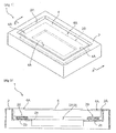
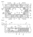
- an information input device 1 includes a housing body 2 forming an opening 2A or the like in its front face which mounts therein a display device 3 having a display portion 3A formed of liquid crystal, organic EL, etc. and mounts also a panel member 4 having a touch type information input function.
- the opening 2A of the housing body 2 is formed by cutting out the upper face of the housing body 2 so as to form a step for allowing fitting-in of the panel member 4. And, on the bottom face thereof, there are provided a display device opening 2a for exposing the display portion 3A of the display device 3 mounted inside the housing body 2 to the outside, and a frame-like support portion 2b for supporting a peripheral portion 4A of the panel member 4.
- the shape and dimension of the opening 2A can vary in many ways, in accordance with the shape and size of the panel member 4. Further, the mounting depth of the opening 2A too can vary in many ways in accordance with e.g. the thickness of the panel member 4. Moreover, the shape and size of the display device opening 2a of the opening 2A can vary in many ways, in accordance with the shape and size or the like of the display portion 3A. In this embodiment, the opening 2A, the display device opening 2a, the display portion 3A and the panel member 4 each have a rectangular or approximately rectangular shape. However, the shapes of the panel member 4, etc. are not particularly limited, but can be circular, for example. The mounting depth of the opening 2A can be set so that the surface of the housing body 2 may be in substantially same level as the surface of the panel member 4.
- the information input device 1 includes a pressure detection unit 20 (or "a pressure detection portion") capable of detecting a press operation to the panel member 4.
- the pressure detection unit 20 is disposed between the panel member 4 and the support portion 2b of the housing body 2 and includes e.g. an unillustrated signal processing circuit for processing output signals.
- the configuration of the pressure detection unit 20 is not particularly limited as long as it is capable of detecting a pressing pressure.
- As shown in Fig. 1 and Fig. 3 as the pressure detection unit 20, at least one thereof is provided in the peripheral portion 4A of the panel member 4.
- the panel member 4 may have the so-called touch input function for detecting X-Y coordinates of an operational position, based on a touch operation to the panel member 4. Of the member having the touch input function, it can be selected from the resistive film type, the electrostatic capacitance type, electromagnetic induction type, etc.
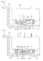
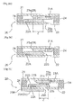
- a frame-like first substrate 21 is disposed and on the side of the support portion 2b, there is disposed a frame-like second substrate 22 facing the first substrate 21.
- a first electrode 21A is disposed relatively on the side of the inner side of the panel member 4.
- the first electrode 21A is coated or covered with an upper pressure sensitive ink layer (or "an upper pressure sensitive ink”) 23a as a pressure sensitive layer 23.
- a second electrode 22A is disposed relatively on the side of the outer side of the panel member 4 and is coated or covered with a lower pressure sensitive ink layer (or "a lower pressure sensitive ink”) 23b as another pressure sensitive layer 23.
- the first electrode 21A and the second electrode 22A are disposed at positions not facing each other on the normal lines of the first substrate 21 and the second substrate 22.
- the second electrode 22A does not hinder the pressing of the first electrode 21A.
- the first electrode 21A does not hinder the pressing of the second electrode 22A.
- a pressure detection unit 20 having improved contact conditions between the pressure sensitive layers 23 and the first and second electrodes 21A, 22A.
- the pressure detection unit 20 is pressed, there occurs no direct mutual pressing between the first electrode 21A and the second electrode 22A. Therefore, it is possible to restrict occurrence of frictional wear of the electrodes which could occur with repeated mutual pressing between the electrodes, so that the durability of the pressure detection unit 20 is improved.
- the inner sizes of the frame-like first substrate 21 and second substrate 22 are matched with the size of the opening 2A, and the outer sizes thereof are matched with an X-Y coordinates detection device (not shown) provided separately.
- the first electrode 21A is disposed in the form of a frame
- the second electrode 22A is disposed in the form of a frame
- the second electrode 22A is disposed to face the position on the opposite side of the center of the panel member relative to the first electrode 21A. That is, as the first electrode 21A and the second electrode 22A are disposed with a spacing therebetween in the horizontal direction, insulating treatment of the first electrode 21A and the second electrode 22A at the portion where the pressure detection unit 20 is not provided can be lessened.
- the pressure detection unit 20 is attached to the opening 2A as the second substrate 22 is bonded on the support portion 2b by means of e.g. an adhesive agent (not shown).
- This connecting portion 24 may comprise e.g. an adhesive bonding agent or a double-face bonding material having elasticity and is formed in a thickness substantially equal to or greater than the combined thickness of the second electrode 22A, the lower pressure sensitive ink layer 23b, the upper pressure sensitive ink layer 23a and the first electrode 21A.
- the electrodes and the pressure sensitive ink layers are spaced apart from the connecting portion 24. However, the pressure sensitive ink layers may be partially in contact with the connecting portion 24.
- the first electrode 21A and the second electrode 22A are connected to a connector (not shown) and this connector is connected to a load detection unit (not shown) incorporated in the information input device 1.
- the pressure detection unit 20 detects change in resistance between the first electrode 21A and the second electrode 22A via the upper pressure sensitive ink layer 23a and the lower pressure sensitive ink layer 23b which occurs in the pressure sensitive layers 23 at the time of a press operation to the panel member 4. Through detection of this resistance change, the external force applied to the pressure sensitive layer 23 can be detected and the load to the panel member 4 can be detected.
- the first substrate 21 and the second substrate 22 of the pressure detection unit 20 can be e.g. films or the like and material forming the same can be one usable for flexible substrates, e.g. general-purpose engineering resin such as polyethylene terephthalate, polystyrene resin, polyolefin resin, ABS resin, AS resin, acrylic resin, AN resin, general-engineering resin such as polystyrene resin, polycarbonate resin, polyacetal resin, polycarbonate modified polyphenylene ether resin, polybutylene terephthalate resin, ultrahigh molecular weight polyethylene resin, or a super-engineering resin such as polysulfone resin, polyphenylene sulfide resin, polyphenylene oxide resin, polyarylate resin, polyetherimide resin, polyimide resin, liquid crystal polyester resin, polyallyl heat resistant resin, etc.
- general-purpose engineering resin such as polyethylene terephthalate, polystyrene resin, polyolefin resin, ABS resin, AS resin, acrylic
- the material for forming the first electrode 21A and the second electrode 22A of the pressure detection unit 20 it is possible to employ a metal such as gold, silver, copper, nickel, etc. or a paste having electrical conductivity containing carbon or a plurality of species of material above.
- a printing method such as screen printing, offset printing, gravure printing, or flexo printing or a photoresist method can be cited.
- the first electrode 21A and the second electrode 22A can be formed by affixing a metal foil of copper, gold, or the like.
- first electrode 21A and the second electrode 22A can be formed also by forming electrode patterns with using a resist on an FPC plated with a metal such as copper and then effecting an etching treatment on the portion of the metal foil not protected with the resist.
- the electrodes can be formed and laminated with any desired combination of the forming methods and materials mentioned above.
- the composition constituting the upper pressure sensitive ink layer 23a and the lower pressure sensitive ink layer 23b of the pressure detection unit 20 comprises a material whose electrical characteristics such as the electrical resistance value varies in response to an external force.
- a material whose electrical characteristics such as the electrical resistance value varies in response to an external force.
- QTC quantum tunnel phenomenon material
- the upper pressure sensitive ink layer 23a and the lower pressure sensitive ink layer 23b can be provided on the first substrate 21 and the second substrate 22 by means of applying thereof.
- a printing method such as screen printing, offset printing, gravure printing, or flexo printing can be employed.
- At least one pressure detection unit 20 is provided, and the unit 20 is respectively bonded to the lower face of the panel member 4 of the information input device 1 by means of an adhesive agent such as paste, or an adhesive layer such as a double-sided bonding tape. And, the pressure detection unit 20 is provided so as to be covered by the ornamental portion in the peripheral portion 4A of the panel member 4. Therefore, the respective components constituting the pressure detection unit 20 need not be formed of a transparent material, but may be formed of a colored material.
- the housing body 2 of the information input device 1, as shown in Fig. 5 may be of a shape having a bezel 2c upwardly of the panel member 4. If such bezel 2c is provided in the housing body 2, the peripheral portion 4A of the panel member 4 and the pressure detection unit 20 disposed in this peripheral portion 4A can be clamped and fixed by the support portion 2b and the bezel 2c of the housing body 2.
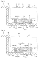
- a frame-like first substrate 21 is disposed and on the side of the support portion 2b, there is disposed a frame-like second substrate 22 on the side of the support portion 2b facing the first substrate 21.
- a first electrode 21A is disposed relatively on the side of the inner side of the panel member 4.
- the first electrode 21A is coated or covered with a first electrically conductive layer 21B.
- a second electrode 22A is disposed relatively on the side of the outer side of the panel member 4 and is coated or covered with a second electrically conductive layer 22B.
- second electrically conductive layer 22B is coated with a pressure sensitive ink layer 23a as another pressure sensitive layer 23.
- the surface of the pressure sensitive ink layer 23a coating the second electrode 22B faces the first electrically conductive layer 21B. Therefore, when the pressure detection unit 20 is pressed by the panel member 4, there is formed, between the first electrically conductive layer 21B and the second electrically conductive layer 22B, an area (pressure sensitive area) Z where the pressure sensitive layers 23 are compressed.
- the first electrode 21A is disposed at a position disposed relatively on the side of the center of the panel member 4 (to the right side in Fig. 6 ) from the pressure sensitive area Z (a position not overlapped with the pressure sensitive area Z).
- the first electrically conductive layer 21B alone is present, so that the possibility of the surface of this first electrically conductive layer 21B being flat and smooth may be higher.
- the contact state between the first electrically conductive layer 21B and the pressure sensitive ink layer 23a in the pressure sensitive area Z is improved, so that the pressure detection characteristics may be stable.
- the material for forming the first electrically conductive layer 21B and the second electrically conductive layer 22B of the pressure detection unit 20 a substantially same or similar material as/to the material forming the first electrode 21A and the second electrode 22B may be employed.
- the electrically conductive paste it is preferred that the paste have particle size smaller than that of the material forming the first electrode 21A and the second electrode 22A. With use of such material having smaller particle size for forming the electrically conductive layers, flat and smooth electrically conductive layers can be readily formed.
- the carbon particles materials having various particle sizes are available. Therefore, by mixing carbon particles of smaller size in the binder and applying the resultant mixture, it is possible to obtain smooth and flat electrically conductive layers having fine surface characteristics.
- the pressure detection unit 20 is configured such that the first electrically conductive layer 21B is coated or covered with a pressure sensitive layer 23.
- the pressure sensitive area Z of the pressure sensitive layer 23 is located between the first electrically conductive layer 21B and the second electrically conductive layer 22B and the first electrode 21A is provided at a position offset from the pressure sensitive area Z in the direction along the first substrate 21.
- a bump 25a which contacts with the support portion 2b as a load transmission member 25 for applying a concentrated load to the pressure sensitive layer 23.
- the bump 25a is disposed to be overlapped with the pressure sensitive area Z, such that when a load is applied to the pressure detection unit 20 from the panel member 4, the bump 25a supports the pressure detection unit 20 from the lower side thereof, thereby to transmit this load in a concentrated manner to the pressure sensitive layer 23 ( Fig. 8 ).
- this can be formed by printing or applying an amount of thermosetting resin or UV setting resin and allowing it to be set, cutting a film or resin plate to a size matching the pressure detection unit and then affixing thereto, a foam member such as PE foam, urethane foam etc., or adhesive bonding agent or double-sided bonding member, a double-side bonding tape, etc.
- a foam member such as PE foam, urethane foam etc., or adhesive bonding agent or double-sided bonding member, a double-side bonding tape, etc.
- the bump 25a will be provided on the back side of the first substrate 21 to contact the panel member 4.
- the height dimension of the bump 25a will range from 50 ⁇ m to 200 ⁇ m for example (including the thickness of the bonding layer for bonding to the second substrate 22).
- a convex portion may be formed at the portion of the housing body 2 corresponding to the pressure sensitive area Z. With provision of such convex portion in the housing body 2 per se, this convex portion functions as the load transmission member 25.
- the pressure detection unit 20 may be configured such that the second electrically conductive layer 22B is coated with the pressure sensitive layer 23, and in reverse arrangement to that in the foregoing embodiment, the second electrode 22A can be provided at a position not overlapped with the pressure sensitive area Z.
- the pressure detection unit 20 includes a first electrode 21A disposed relatively on the side of the center of the panel member 4, a second electrode 22A disposed relatively on the side of the counter-center side of the panel member 4.
- a first electrically conductive layer 21B coating the first electrode 21A includes a first extension portion 21b extending toward the counter-center side
- a second electrically conductive layer 22B includes a second extension portion 22b extending toward the center side.
- the first electrically conductive layer 21B and the second electrically conductive layer 22B are disposed substantially parallel in the vertical direction, and a portion of the second extension portion 22b is coated with the pressure sensitive layer 23, and the pressure sensitive layer 23 is disposed between the first extension portion 21b and the second extension portion 22 to form the pressure sensitive area Z therein.
- the first electrode 21A and the second electrode 22A are provided at positions not overlapped with the pressure sensitive area Z.
- first electrode 21A and the second electrode 22A at positions not overlapped with the pressure sensitive area Z as described above, it becomes possible to provide the component surfaces of the first electrically conductive layer 21B and the second electrically conductive layer 22B with smooth and flat finish. Hence, the contact between the pressure sensitive layer 23 and the first and second electrically conductive layer 21B, 22B becomes more reliable, so that there is obtained a pressure detection unit 20 having high reliability.
- the pressure sensitive ink layer 23a coats only the second extension portion 22b in the second electrically conductive layer 22B. Therefore, even when the pressure sensitive layer 23 is compressed, the second electrode 22A is not pressed directly. Hence, the second electrode 22A is less vulnerable to damage in the case of excessive press operation on the panel member, so that the durability of the pressure detection unit 20 is improved.
- the pressure detection unit 20 includes a first electrode 21A disposed relatively on the side of the center of the panel member 4, a second electrode 22A disposed relatively on the counter-center side of the panel member 4.
- a first electrically conductive layer 21B coating the first electrode 21A includes a first extension portion 21b extending toward the counter-center side and the second electrically conductive layer 22B includes a second extension portion 22b extending toward the center side.
- the first electrically conductive layer 21B and the second electrically conductive layer 22B are disposed such that only the respective extension portions 21b, 22b thereof are overlapped with each other, and a portion of the second extension portion 22b is coated with the pressure sensitive layer 23, and the pressure sensitive layer 23 is provided between the first extension portion 21b and the second extension portion 22b to form the pressure sensitive area Z therein.
- both electrodes 21A, 22A are provided at positions not overlapped with the pressure sensitive area Z.
- the second electrically conductive layer 22B is not present at the position where the first electrode 21A is located on the normal line relative to the second substrate 22. And, at the position where the second electrode 22A is located on the normal line relative to the first substrate 21, the first electrically conductive layer 21B is not present. Therefore, as contacts between the first electrode 21A and the second electrically conductive layer 22B and between the second electrode 22A and the first electrically conductive layer 21B are avoided reliably. As a result, the detection accuracy of the pressure detection unit 20 is improved. Further, as shown in Fig.
- a frame-like first substrate 21 is disposed and on the side of the support portion 2b, there is disposed a frame-like second substrate 22 facing the first substrate 21.
- a first electrode 21A is disposed and on the second substrate 22, a second electrode 22A is disposed.
- the first electrode 21A is coated or covered with an upper pressure sensitive ink layer 23a and the second electrode 22A is coated or covered with a lower pressure sensitive ink layer 23b.
- the electrodes 21A, 22A may be coated with the electrically conductive layers 21B, 22B, respectively.
- the pressure sensitive layers 23 may be a single layer of pressure sensitive ink.
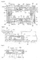
- a first electrode 21A is disposed in the form of a frame.
- a second electrode 22A facing the first electrode 21A.
- upper pressure sensitive ink layers 23a in the form of dots covering the first electrode 21A.
- lower pressure sensitive ink layers 23b in the form of dots covering the second electrode 22A and facing the upper pressure sensitive ink layers 23a.
- the electrodes at the pressure sensitive ink layer portions are sized to be slightly smaller than the printing sizes of the pressure sensitive ink layers and are attached to the opening 2A as being affixed thereto.
- the pressure sensitive unit 20 further includes a bump 25a between the second substrate 22 and a support portion 2b of the housing body, the bump acting as a load transmission member 25 which contacts the support portion 2b to apply a concentrated load to the pressure sensitive layer 23.
- the first electrode 21A and the second electrode 22A compress the pressure sensitive layers 23, thus forming a pressure sensitive area Z.
- the bump 25a forms a load transmission area A between the second substrate 22 and the support portion 2b of the housing body.
- the load transmission member 25 is configured such that a portion of the edge thereof is overlapped with the pressure sensitive area Z and the other edge portion thereof is not overlapped with the pressure sensitive area Z, as seen along the direction of the normal line of the panel member 4.
- the bump 25a supports the pressure detection unit 20 from the lower side thereof, thus transmitting this load in a concentrated manner to the pressure sensitive unit 20 ( Fig. 14 ). Further, as the edge portion 25A on the center side of the panel member 4 acts as a "corner portion", a local press force is applied to the second substrate 22. With this, the pressure detection unit 20 can detect even a small press force in a reliable manner.
- this can be formed by printing or applying an amount of thermosetting resin or UV setting resin and allowing it to be set, cutting a film or resin plate to a size matching the pressure detection unit and then affixing thereto, a foam member such as PE foam, urethane foam etc., or adhesive bonding agent or double-sided bonding member, a double-aide bonding tape, etc.
- the bump 25a may be provided either between the first substrate 21 and the panel member 4 alone or may be provided between the first substrate 21 and the panel member 4 as well as between the second substrate 22 and the support portion 2b of the housing body. In this, the height dimension of the bump 25a will range from 50 ⁇ m to 200 ⁇ m for example (including the thickness of the bonding layer for bonding to the second substrate 22).
- a convex portion may be formed at the portion of the housing body 2 corresponding to the pressure sensitive area Z. With provision of such convex portion in the housing body 2 per se, this convex portion functions as the load transmission member 25.
- the connecting portion 24 functions like a "knot", which makes it difficult for the first substrate and the second substrate to approach each other.
- a portion 25A of the edge of the load transmission member 25 is overlapped with the pressure sensitive area Z, and the other edge portion 25B is overlapped with the connecting portion 24.
- the amount of change in the distance between the first substrate 21 and the second substrate 22 is smaller than e.g. the amount of change in the pressure sensitive area Z. Then, when the panel member 4 is deformed as receiving a press force, a greater load will be applied to a portion where mutual approaching between the first substrate 21 and the second substrate 22 is easier, that is, at a portion corresponding to the pressure sensitive area Z.
- a portion of the edge 25A of the load transmission member 25 is overlapped with the pressure sensitive area Z and a portion of the other edge 25B is located on the outer edge side of the panel member 4 relative to the pressure sensitive area Z; and at the outer edge of the panel member 4, the edge of the first substrate 21, the connecting portion 24, the edge of the second substrate 22 and a potion of the rest edge 25B of the load transmission member 25 are overlapped with each other.
- the area from the edge of the first substrate 21 to the edge 25B of the load transmission member 25 is disposed on the outermost side of the panel member 4.
- this portion the outer edge of the panel member 4, functions as a "reaction force receiving portion" when a press force is applied to the panel member 4. Then, the panel member 4 will be flexed and deformed with the center portion thereof being pushed in relative to this edge portion as the pivot thereof. With the provision of such reaction force receiving portion in the outermost edge of the panel member 4 and resultant increase of the distance from the center position of the panel member 4, it becomes possible to cause the panel member 4 to be deformed maximally in response to application of a same amount of press force.
- the edge 25A thereof is located at the position in the pressure sensitive area Z, so that this edge portion 25A will press the pressure sensitive area Z in a concentrated manner.
- the arrangement is provided for allowing maximal flexing deformation of the panel member 4 as described above, the amount of pressing to the pressure sensitive layers 23 will be increased and the detection sensitivity of the pressure detection unit 20 will be improved.
- the connecting portion from the edge of the first substrate 21 to the load transmission member 25 is disposed on the outermost side of the panel member 4 and the load transmission member 25 is constituted of an adhesive member and this adhesive member is provided along the entire periphery of the panel member 4, it is possible to prevent intrusion of foreign substance or water from the outer peripheral side of the panel member 4.
- the first electrode 21A is disposed relatively on the side of the inner side of the panel member 4 and on the second substrate 22, the second electrode 22A is disposed relatively on the side of the outer side of the panel member 4. More particularly, the first electrode 21A and the second electrode 22A are disposed at positions not facing each other on the normal lines of the first substrate 21 and the second substrate 22.
- the first electrode 21A is coated or covered with an upper pressure sensitive ink layer 23a as a pressure sensitive layer 23 and the second electrode is coated or covered with a lower pressure sensitive ink layer 23b as another pressure sensitive layer 23.
- the first electrode 21A and the second electrode 22A are disposed at positions not facing each other on the normal lines of the first substrate 21 and the second substrate 22. With this, it is possible to alleviate the influence from unevenness in the thickness or surface of the electrode portions 21A, 22A which may affect the pressure sensitive layers 23.
- the first electrode 21A is pressed against the pressure sensitive layer 23, the second electrode 22A does not hinder the pressing of the first electrode 21A.
- the second electrode 22A is pressed against the pressure sensitive layer 23, the first electrode 21A does not hinder the pressing of the second electrode 22A.
- a pressure detection unit 20 having improved contact conditions between the pressure sensitive layers 23 and the first and second electrodes 21A, 22A.
- the first electrode 21A may be disposed on the counter-center side of the panel member 4 on the first substrate 21 and the second electrode 22A may be disposed on the center side of the panel member 4 on the second substrate 22.
- the first electrode 21A is disposed on the inner side of the panel member 4 and the first electrode 21A is coated with the first electrically conductive layer 21B.
- the second electrode 22A is disposed on the outer side of the panel member 4 and the second electrode 22A is coated with the second electrically conductive layer 22B. That is, in this embodiment too, the first electrode 21A and the second electrode 22A are provided at positions not facing each other on the normal lines of the first substrate 21 and the second substrate 22. Further, the first electrically conductive layer 21B is coated with a pressure sensitive ink layer 23a as a pressure sensitive layer 23.
- the surface of the pressure sensitive ink layer 23a coating the first electrically conductive layer 21B faces the second electrically conductive layer 22B.
- a pressure sensitive area Z where the pressure sensitive layer 23 is compressed.
- the first electrode 21A is disposed at position offset from the pressure sensitive area Z toward the center side of the panel member 4 (the right side in Fig. 18 ). That is, the first electrode 21A is provided at a position not overlapped with the pressure sensitive area Z.
- the first electrically conductive layer 21B alone is present.
- the first electrode 21A may be disposed on the counter-center side of the panel member 4 on the first substrate 21 and the second electrode 22A may be disposed on the center side of the panel member 4 on the second substrate 22.
- the information input device 1 when the panel member 4 whose peripheral portion 4A is fixed is pressed, the peripheral portion 4A tends to float due to flexure of the panel member 4. This floating action can cause reduction in the accuracy of the pressure detection unit 20 disposed in the peripheral portion 4A. Then, the information input device 1 shown in Fig. 19 includes a floating prevention mechanism for preventing floating of a corner portion 4B of the panel member 4 off the housing body 2. Three pressure detection units 20 are provided on the long side of the peripheral portion 4A of the rectangular panel member 4 and one pressure detection unit 20 is provided on the short side thereof, excluding the corner portion 4b, However, the disposing layout and the disposing number of the pressure detection units 20 are not limited to the above.
- the pressure detection unit 20 may be provided in the corner portion 4B.
- corner portion 4B refers to a predetermined area from the corner of the panel member 4. For example, this can be the area of 1/4 distance of the straight distance connecting between the center of the panel member 4 and the pressure detection unit 20 disposed closest to this center.
- Fig. 21 is a plane view showing the arrangement of the floating prevention mechanism.
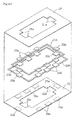
- the floating prevention mechanism in this embodiment is constituted by providing the projection 21a of the first substrate 21 and the projection 22a of the second substrate 22 with a wide bonding member 24a, a wide upper bonding portion 31a and a wide lower bending portion 32a.
- the areas of the first substrate 21 and the second substrate 22 covering the wide upper bonding member 31a and the wide lower bonding portion 32a need not be constituted as the projections 21a, 22a. Instead, these may be constituted of portions of the first substrate 21 and second substrate 22 in the form of frames with a predetermined width, not having the projections 21a, 22a.
- Fig. 22 is a section along XXII-XXII in Fig. 21 , that is, a section of the peripheral portion 4A where the pressure detection unit 20 is formed.
- the lower face of the panel member 4 and the upper face of the first substrate 21 are bonded to each other via an upper bonding portion 31 and the upper face of the support portion 2b of the housing body 2 and the lower face of the second substrate 22 are bonded via a bump 25a comprising a double-sided adhesive tape.
- adhesive agent such as paste, a double-sided adhesive tape, etc. can be employed.
- Fig. 23 is a section along XXIII-XXIII in Fig. 21 , that is, a section of the corner portion 4B where the pressure detection unit 20 is not formed.
- the corner portion 4B there are provided projections 21a, 22a projecting from the inner frame of the first substrate 21 and the second substrate 22 toward the inner side.
- a wide bonding member 24a, a wide upper bonding portion 31a and a wide lower bonding portion 32a can be provided, so that the bonding area in the corner portion 4B can be larger.
- the bonding force in the corner portion 4B is increased and it becomes possible to prevent the floating of the panel member 4.
- the pressure sensitive ink layers 23a, 23b are not provided, so that this portion does not function as the pressure detection unit 20. Therefore, even if the corner portion 4B of the panel member 4 should float, as no pressure is detected in this corner portion 4B, the detection accuracy of the pressure detection unit 20 can be improved.
- No projections may be provided in the first substrate 21 and the second substrate 22.
- bonding portions 33 for directly bonding between the panel member 4 and the support portion 2b of the housing body 2 may be provided as the floating prevention mechanism.
- the bonding portion 33 With provision of the bonding portion 33, the bonding area in the corner portion 4B is increased, so that the floating of the corner portion 4B of the panel member 4 can be prevented.
- the bonding portion 33 can be e.g. an adhesive bonding agent or a double-sided adhesive member having elasticity. Incidentally, it is not absolutely needed for the bonding portion 33 to be in contact with the first substrate 21 and the second substrate 22.
- the bonding portion 33 and the fast and second substrate 21, 22 can be partially spaced from each other.
- a concave portion 4C may be provided in a lateral face of the corner portion 4B of the panel member 4 and a convex portion 2d engageable with the concave portion 4C may be provided in the housing body 2.
- the convex portion 2d prevents floating of the corner portion 4B of the panel member 4
- reduction in the detection accuracy of the pressure detection unit 20 due to the floating phenomenon can be prevented.
- the convex portion 2d can be replaced by a concave portion and the concave portion 4C can be replaced by a convex portion.
- an initial load may be applied in advance to the pressure sensitive layers 23.
- the connecting portion 24 is comprised of a non-elastic spacer (including the bonding layers to the substrates 21, 22, this can be an adhesive bonding agent alone) whose thickness is smaller than the thickness of the pressure sensitive portion (electrodes, electrically conductive layers, and pressure sensitive layers). With this, in case deformation of the first substrate 21 or the second substrate 22 is allowed, the first substrate 21 or the second substrate 22 applies a preset pressure as an initial load to the pressure detection unit 20.
- the connecting portion 24 can be an adhesive bonding agent or double-sided bonding member having elasticity or various kinds of elastic members such as rubber, a tension coil spring, a plate spring in a condition for exerting a tensile force.
- the thickness of the pressure sensitive portion may be increased to be greater than the thickness of the connecting portion 24, thereby to apply an initial load to the pressure sensitive layers 23.
- this may be realized for instance by printing or applying the electrode 21A, 22A, the electrically conductive layer 22A or 22B or the pressure sensitive layer 23 in a thickness greater than the normal thickness or recoating the same.
- the first electrically conductive layer 21B may be coated with the upper pressure sensitive ink layer 23a and the second electrically conductive layer 22B may be coated with the lower pressure sensitive ink layer 23b, and the first electrode 21A and the second electrode 22A are provided at positions not overlapped with the pressure sensitive area Z.
- the pressure detection unit 20, as shown in Fig. 29 may be configured such that the first electrode 21A and the second electrode 22A are not coated with the electrically conductive layers 21B, 22B, but are coated directly with the upper pressure sensitive ink layer 23a and the lower pressure sensitive ink layer 23b, and the first electrode 21A and the second electrode 22A are provided at positions not overlapped with the pressure sensitive area Z:
- the pressure detection unit 20 may be configured such that either one of the first electrode 21A and the second electrode 22A (the second electrode 22A in the case of the illustration in Fig. 30 ) is coated with an electrically conductive layer (the second electrically conductive layer 22B in the case of the illustration in Fig. 30 ) and either the other of the first electrode 21A and the second electrode 22A (the first electrode 21A in the case of the illustration in Fig. 30 ) is coated directly with the pressure sensitive layer 23.
- the load transmission member 25 provided in the pressure detection unit 20 may be disposed such that one edge 25A thereof is overlapped with the pressure sensitive area Z and the other edge 25B thereof is not overlapped with the pressure sensitive area Z.
- the other edge 25B may be disposed on the counter-center side of the panel member 4 relative to the pressure sensitive area Z or conversely this may be on the center side of the panel member 4 relative to the pressure sensitive area Z.
- the bump 25a is formed of an adhesive material, as shown in Fig. 31 , by disposing the area from the edge of the first substrate 21 to the edge 25B of the load transmission member 25 on the outermost side of the panel member 4, it is possible to prevent intrusion of foreign substance or water from the outer peripheral side of the panel member 4. Hence, the reliability and durability of the device can be improved. Further, since unnecessary edge portions of the pressure detection unit 20 and the load transmission member 25 can be eliminated, the pressure detection unit 20 can be manufactured easily.
- the load transmission member 25 may be configured such that as seen in the direction of the normal line of the panel member 4, the counter-center side edge of the panel member 4 is overlapped with the pressure sensitive area Z and the center side edge of the panel member 4 is not overlapped with the pressure sensitive area Z.
- the first electrode 21A was provided at a position not overlapped with the pressure sensitive area Z.
- the second electrode 22A may be provided at a position not overlapped with the pressure sensitive area Z.
- both the first electrode 21A and the second electrode 22A may be provided at positions not overlapped with the pressure sensitive area Z.
- the first electrically conductive layer 21B will include a first extension portion 21b extending laterally relative to the first electrode 21A and the second electrically conductive layer 22B will include a second extension portion 22b extending laterally relative to the second electrode 22A.
- the pressure sensitive ink layer 23a coats only the first extension portion 21b of the first electrically conductive layer 21B and the pressure sensitive layer 23 is disposed between the first extension portion21b and the second extension portion 22b, in the course of a press operation to the panel member 4, the pressure sensitive layer 23 will be compressed by the first extension portion 21b and the second extension portion 22b. That is, even when the pressure sensitive layer 23 is compressed, the first electrode 21A and the second electrode 22A are not directly pressed. Hence, with the above arrangement, the first electrode 21A and the second electrode 22A will be less vulnerable to damage to an excessive press operation to the panel member 4, so that the durability of the pressure detection unit 20 can be improved.
- the pressure detection unit 20 having the bump 25a can be configured such that a pair of electrodes provided in either the first substrate 21 or the second substrate 22, and the other one of the first substrate 21 and the second substrate 22 is disposed to coat the pair of electrodes. With this, the electrode layer becomes a single layer, so that the thickness of the pressure detection unit 20 is further reduced. As a result, the information input device 1 can be formed thinner. In this case, if the pair of electrodes are provided in the form of comb teeth or coils, or the like for controlling the area of contact with the pressure sensitive ink members, it is possible to obtain signals in favorable detection range.
- a pressure detection unit 20 shown in Fig. 34 is identical to the pressure detection unit 20 shown in Fig. 22 except that a bump member 25 is disposed between the panel member 4 and the first substrate 21. If an arrangement is made such that of the edges of the bump 25a, the edge 25A on the center side of the panel member 4 is located between the first electrode 21A and the second electrode 22A, when the panel member 4 is pressed, the press force will be transmitted in a concentrated manner from the edge 25A of the bump 25a to the upper pressure sensitive ink layer 23a and the lower pressure sensitive ink layer 23b. Therefore, such arrangement is preferred.
- the bump 25a was provided on the outer half of the pressure detection unit 20. Instead, a bump 25a having a smaller width than the pressure sensitive ink layer 24a, 24b may be provided downwardly of the pressure sensitive ink layer 23a, 23b. Further, the bump 25a may be disposed between the second substrate 22 and the lower pressure sensitive ink layer 23b or between the first substrate 21 and the upper pressure sensitive ink layer 23a. Further alternatively, the dumps 25a may be provided at plural positions of these.
- the connecting portion 24 of the pressure detection unit 20 may be provided only on one side of either the counter-center side or the center side of the panel member 4.
- the connecting portion 24 is disposed on the counter-acenter side (outer side) of the panel member 4, it is possible to prevent intrusion of foreign substance or water through the gap between the panel member 4 and the device main body. Hence, there is no possibility of foreign substance getting stuck between the panel member 4 and the support portion 2b. Further, the chance of damage to the first electrode 21A, the second electrode 22A or the pressure sensitive layer 23 can be reduced. So that the durability of the device will be improved significantly.
- the first electrode 21A is disposed on the center side of the panel member 4 and the second electrode 22A is disposed on the counter-center side of the panel member 4. Conversely, the first electrode 21A may be disposed on the counter-center side of the panel member 4 and the second electrode 22A may be disposed on the center side of the panel member 4.
- the pressure sensitive layer 23 may be provided on at least a part of the peripheral portion 4A of the panel member 4.
- the connecting portion 24 may be provided only in the vicinity of the pressure sensitive layer 23. If the connecting portion 24 is provided on a part of the peripheral portion 4A of the panel member 4 as described above, the connecting portion 24 can be provided only at position where it is needed. Hence, when e.g. the number of pressure detection units 20 to be disposed in the panel member 4 is small, the above-mentioned configurations will be advantageous in the manufacture of the information input device 1.
- the pressure detection unit relating to the present invention may be effectively used in various electronic devices or instruments such as a mobile telephone, a smart phone, a PDA, a car navigation device, a digital camera, a digital video camera, a game machine, a tablet, etc., and can be utilized for realization of multiple functions and improvement of the operability of the electronic device or instrument.
Landscapes
- Engineering & Computer Science (AREA)
- General Engineering & Computer Science (AREA)
- Theoretical Computer Science (AREA)
- Human Computer Interaction (AREA)
- Physics & Mathematics (AREA)
- General Physics & Mathematics (AREA)
- Force Measurement Appropriate To Specific Purposes (AREA)
- Push-Button Switches (AREA)
- Position Input By Displaying (AREA)
Abstract
Description
- The present invention relates to a pressure detection unit for an information input device enabling input of information through detection of a press operation to a panel member and relates also to the information input device having the pressure detection unit.
- As an information input device including a panel member having an information input functions, a device having a touch panel disposed on a liquid crystal display is being widely used. In the case of a digital camera having a liquid crystal monitor, there is known one configured such that on an upper face of the liquid crystal monitor there is disposed a panel member capable of detecting a contact position and a press force, so that in accordance with the strengths of the press at the time of contact, different instructions are given (see
e.g. Patent Document 1,Fig. 36 ). - In a
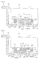
pressure detection unit 20 to be mounted on the information input device described above, for example, as shown inFig. 37 , between thefirst substrate 21 and thesecond substrate 22, from the side of thesecond substrate 22, there are arranged asecond electrode 22A, acarbon layer 22B, a pressuresensitive ink layer 23a and afirst electrode 21A in this mentioned order, so that the detection unit determines a pressure when the touch panel or the like is pressed down, and information in accordance with a determined pressure value is instructed for its input. - Patent Document 1: Japanese Unexamined Patent Application Publication No.
11-355617 - In the pressure detection unit shown in
Fig. 37 , on thesecond electrode 22A on the side of thesecond substrate 22, thecarbon layer 22B is printed as being superposed thereon, a pressuresensitive ink layer 23a is coated on thecarbon layer 22B, and thefirst electrode 21A is provided on the other side of thefirst substrate 21. In this case, as compared with thecarbon layer 22B, theelectrode portions carbon layer 22B contacting the pressuresensitive ink layer 23a is not smooth and flat. This results in instability in the condition of contact between the pressuresensitive ink layer 23a and theelectrode layers - In the case of a pressure detection unit shown in
Fig. 38 , for enabling effective transmission of a load inputted from the outside to the pressuresensitive ink layer 23a, aload transmission member 25 is disposed on the side of thesecond substrate 22 opposite thesecond electrode 22A, with theload transmission member 25 being located immediately below the pressuresensitive layer 23. - However, in the case of the arrangement wherein the pressure detection unit is disposed in a peripheral portion of the
panel member 4, in response to a press operation to the center portion of thepanel member 4, a certain amount of bending deformation will occur in thepanel member 4, which leads to a change in the posture of thepanel member 4 also in the periphery of thepanel member 4 as seen in the side view in section. With such change in the posture of thepanel member 4, the postures of thefirst substrate 21 and thesecond substrate 22 will also change. Therefore, even if theload transmission member 25 is provided on thesecond substrate 22, a load inputted form the outside may sometimes be not transmitted sufficiently to the pressuresensitive layer 23. - The object of the present invention is to obtain a pressure detection unit having improved accuracy in sensitivity and an information input device having the pressure detection unit, so that the information input device may effect more reliable information input with a press operation.
- According to a first characterizing feature of a pressure detection unit relating to the present invention, a pressure detection unit disposed in a peripheral portion of a panel member of an information input device in order to detect a press operation to the panel member, the pressure detection unit comprises: a first substrate; a second substrate disposed to face the first substrate; pressure sensitive layers disposed between the first substrate and the second substrate; and a first electrode provided on the first substrate and a second electrode provided on the second substrate for detecting resistance change via the pressure sensitive layers, respectively; wherein the first electrode and the second electrode are provided at positions not facing each other on normal lines of the first substrate and the second substrate.
- In forming a pressure detection unit in an information input device, for instance, pressure sensitive layers are formed on the first electrode, and these respective layers are formed by applying an amount of layer forming material. In this, since the electrode portion has unevenness in its thickness and/or its surface, the surface of the finished pressure sensitive layer is not always formed flat and smooth. Similarly, on the second electrode too, a pressure sensitive layer will be formed if necessary. In this case, when the pressure sensitive layers are pressed between and by the first substrate and the second substrate by applying a press force to the panel member, it may sometimes happen that the pressure sensitive layers or the pressure sensitive layer and the electrode fail to come into contact with each other through the flat surfaces, but convex portions thereof come into contact with each other. As a result, the electrical conduction state between the contacting components is not stable, so the pressure detection unit functions in an unstable manner.
- However, with the above-described arrangement, since the first electrode and the second electrode are provided at positions not facing each other on normal lines of the first substrate and the second substrate, the influence of the irregularity in the thickness or surface of the electrode portion affecting the pressure sensitive layers can be alleviated. As a result, there can be obtained a pressure detection unit having improved contact state between the pressure sensitive layers and the electrodes. Further, even when the pressure detection unit is pressed, this does not result in direct pressing of the first electrode and second electrode against each other. Therefore, such inconvenience of mutual pressing between electrodes leading to damage thereof can be restricted and the durability of the pressure detection unit can be improved.
- According to a second characterizing feature of the pressure detection unit according to the present invention, at least one of the first electrode and the second electrode is provided at a position not overlapped with a pressure sensitive area where the pressure sensitive layers are compressed when the pressure detection unit is pressed.
- With this arrangement, since either one of the electrodes is provided at a position not overlapped with the pressure sensitive area, the pressure sensitive area can be free from the influence of the irregularity in the thickness or surface of the electrode portion. Therefore, the possibility of the surface of a least one of the pressure sensitive layers in this area being smooth and flat becomes higher. As a result, the contact state between the pressure sensitive layers and the electrodes is improved and the pressure detection characteristics becomes stable, so that a pressure detection unit having even higher reliability can be obtained. Consequently, it has become possible for the information input device to achieve reliable information input with a press operation.
- According to a third characterizing feature of the pressure detection unit according to the present invention, the first electrode and the second electrode are provided at positions not overlapped with the pressure sensitive area.
- With the above arrangement of both electrodes being provided at positions not overlapped with the pressure sensitive area, it becomes possible to provide the surfaces of both components, i.e. the first electrode and the second electrode, with smooth and flat finish. Therefore, the contact of the pressure sensitive layers in the pressure sensitive area becomes even more reliable, so that a pressure detection unit with even higher reliability can be obtained.
- According to a fourth characterizing feature of the pressure detection unit relating to the present invention, at least one of the fast electrode and the second electrode is coated with an electrically conductive layer.
- In case the electrode of the pressure detection unit is coated directly with the pressure sensitive layer, depending on the characteristics of the material used in the electrode, the electrode may be damaged by the compressed pressure sensitive layer. With the above-described arrangement, however, since the electrode is protected as being coated with an electrically conductive layer, the electrode can be less vulnerable to damage or the like. As a result, the durability of the pressure detection unit is improved.
- According to a fifth characterizing feature of the pressure detection unit relating to the present invention, the pressure detection unit further comprises: a first electrically conductive layer coating the first electrode and a second electrically conductive layer coating the second electrode; wherein the first electrically conductive layer includes a first extension portion extending laterally relative to the first electrode, the second electrically conductive layer includes a second extension portion extending laterally relative to the second electrode; the pressure sensitive layers coat at least one of the first extension portion and the second extension portion; and when the pressure detection unit is pressed, the pressure sensitive layers are compressed only by the first electrically conductive layer relating to the first extension portion and the second electrically conductive layer relating to the second extension portion.
- With the above arrangement, in forming the first electrically conductive layer and the second electrically conductive layer, electrically conductive layers having extremely smooth and flat surfaces can be formed in the region where the first electrode and the second electrode which per se are projections are not existent. Also, when the pressure sensitive layer is formed on the surface of one of these electrically conductive layers, since the electrically conductive layer as the base therefor is smooth and flat, a pressure sensitive layer having substantially same smoothness as the electrically conductive layer can be obtained. Therefore, with the arrangement of the pressure sensitive layers being compressed only in the regions of the first extension portion and the second extension portion, the contact may be rendered appropriate over a larger area, so that a pressure detection unit having stable detection characteristics can be obtained.
- According to a sixth characterizing feature of the pressure detection unit relating to the present invention, the first electrically conductive layer and the second electrically conductive layer are comprised of carbon layers containing carbon particles mixed with binder .
- Normally, carbon particles are available in variety of particle sizes. Then, by mixing such carbon particles in the binder and applying the resultant mixture, it is possible to obtain smooth electrically conductive layers having fine surface characteristics. Therefore, since it becomes possible to obtain a large contact area in compressing the pressure sensitive layers, it is possible to obtain a pressure detection unit having superior electrical conductivity characteristics.
- According to a seventh characterizing feature of the pressure detection unit relating to the present invention, the pressure detection unit further comprises a load transmission member provided on the outer face of at least one of the first substrate and the second substrate for applying a concentrated load to the pressure sensitive layers.
- With the above arrangement, when a load is applied from the outside to the pressure detection unit, as the load transmission member supports the pressure detection unit, the external load can be received in a concentrated manner without dissipation thereof and this load can be transmitted reliably to the pressure sensitive layers. As the pressure sensitive layers are pressed reliably as described above, the detection accuracy of the pressure detection unit can be improved.
- According to an eighth characterizing feature of the pressure detection unit relating to the present invention, a pressure detection unit disposed in a peripheral portion of a panel member of an information input device in order to detect a press operation to the panel member, the pressure detection unit comprises: a first substrate; a second substrate disposed to face the first substrate; pressure sensitive layers disposed between the first substrate and the second substrate; and a first electrode provided on the first substrate and a second electrode provided on the second substrate for detecting resistance change via the pressure sensitive layers, respectively; and a load transmission member provided on the outer face of at least one of the first substrate and the second substrate for applying a concentrated load to the pressure sensitive layers: and wherein relative to a pressure sensitive area formed by compression of the pressure sensitive layers when the pressure detection unit is pressed, as seen along the direction of normal line of the panel member, a portion of the edge of the load transmission member is overlapped with the pressure sensitive area and the rest of the edge is not overlapped with the pressure sensitive area.
- When the pressure detection unit is pressed, the first substrate or the second substrate receives a local load from the load transmission member. Then, there occurs a certain amount of bending deformation in the panel member and in the periphery of the panel member also, there occurs a change in the posture of the panel member sideways as seen in the cross section. In association with this, there occurs a change also in the posture of the first substrate or the second substrate. As a result, the contact posture of the load transmission member relative to the first substrate or the second substrate will change.
- According to the present invention, in order to utilize such change in the relative posture between the first or the second substrate and the load transmission member, an arrangement is provided such that a portion of the edge of the load transmission member is overlapped with the pressure sensitive area and the rest of the edge is not overlapped with the pressure sensitive area as seen along the direction of normal line of the panel member. That is, when the first substrate or the second substrate contacting the load transmission member is inclined, the edge of the load transmission member functions as a corner portion, thus applying a localized press force to the first substrate or the like. With this, it becomes possible for the pressure detection unit to detect even a small and weak press force in a reliable manner. Hence, the detection characteristics of the pressure detection unit can be improved.
- According to a ninth characterizing feature of the pressure detection unit relating to the present invention, the first substrate and the second substrate are connected with each other via a connecting portion at a position different from the pressure sensitive area, as seen along the direction of the normal line of the panel member, a portion of the rest of the edge of the load transmission member is overlapped with the connecting portion.
- According to the ninth arrangement of the pressure detection unit relating to the present invention, the first substrate and the second substrate are connected with each other via a connecting portion at a position different from the pressure sensitive area. In the case of this arrangement, when the first substrate and the second substrate are pressed against each other in response to pressing of the pressure detection unit, the connecting portion functions like a "knot". More particularly, it may become difficult for the first substrate and the second substrate to come closer to each other at the area of the connecting portion. Hence, there arises the possibility of the press force to the pressure detection unit being not sufficiently transmitted to the pressure sensitive area.
Then, with the above-described arrangement that as seen along the direction of the normal line of the panel member, the edge of the load transmission member is overlapped with the pressure sensitive area, the edge of the load transmission member functions as a corner portion, so that via this portion, the pressure sensitive layers can be pressed in a reliable manner. - When the first substrate and the second substrate approach each other and are deformed when the pressure detection unit is pressed, at the portion of the connecting portion, the amount of change in the distance between the first substrate and the second substrate is smaller than e.g. the amount of change in the pressure sensitive area. Then, when the panel member is deformed as receiving a press force, a greater load will be applied to a portion where mutual approaching between the first substrate and the second substrate is easier, that is, at a portion corresponding to the pressure sensitive area.
- In view of the above, the above arrangement wherein the position of one edge of the load transmission member is provided as the portion of the connecting portion so that the first substrate or the second substrate may be flexed relative to this position as the pivot will be most reasonable. That is, this will eliminate the necessity of extending the load transmission member from the position of the contacting portion toward the side of the pressure sensitive area and extending it even further. Rather, by avoiding excessive extension of the load transmission member, there will be no component that would restrict the first substrate or the second substrate, so that there is obtained greater freedom in the deformation at this portion. As a result, it becomes possible for the first substrate or the like to be bent or flexed even greatly, thus increasing the press-in amount of the pressure sensitive area by the portion of the edge of the load transmission member. In this way, there can be obtained a pressure detection unit having even superior detection characteristics.
- According a tenth characterizing feature of the pressure detection unit relating to the present invention, as seen along the direction of normal line of the panel member, a portion of the rest of the edge of the load transmission member is located on the outer edge side of the panel member relative to the pressure sensitive area; and at the outer edge of the panel member, the edge of the first substrate, the connecting portion, the edge of the second substrate and a potion of the rest of the edge are overlapped with each other.
- With the above arrangement, the edge of the first substrate, the connecting portion, the edge of the second substrate and a potion of the rest of the edge are overlapped with each other at the outer edge of the panel member. With this, this portion functions as a reaction force receiving portion when a press force is applied to the panel member. Then, the panel member will be flexed and deformed with the center portion thereof being pushed in, relative to this edge portion as the pivot thereof. With the provision of such reaction force receiving portion in the outermost edge of the panel member and resultant increase of the distance from the center position of the panel member, it becomes possible to cause the panel member to be deformed maximally in response to application of a same press force.
- On the other hand, of the load transmission member, the other edge thereof is located at the position in the pressure sensitive area, so that this edge portion will press the pressure sensitive area in a concentrated manner. In this, since the arrangement is provided for allowing maximal flexing deformation of the panel member as described above, the amount of pressing to the pressure sensitive layers will be increased and the detection sensitivity of the pressure detection unit will be improved.
- According to an eleventh characterizing feature of the pressure detection unit relating to the present invention, the first electrode and the second electrodes are provided at positions not facing each other on the normal lines of the first substrate and the second substrate.
- In forming a pressure detection unit in an information input device, for instance, pressure sensitive layers are formed on the first electrode, and these respective layers are formed by applying an amount of layer forming material. In this, since the electrode portion has unevenness in its thickness and/or its surface, the surface of the finished pressure sensitive layer is not always formed flat and smooth. Similarly, on the second electrode too, a pressure sensitive layer will be formed if necessary. In this case, when the pressure sensitive layers are pressed between and by the first substrate and the second substrate by applying a press force to the panel member, it may sometimes happen that the pressure sensitive layers or the pressure sensitive layer and the electrode fail to come into contact with each other through the flat surfaces, but convex portions thereof come into contact with each other. As a result, the electrical conduction state between the contacting components is not stable, so the pressure detection unit functions in an unstable manner.
- However, with the above-described arrangement, since the first electrode and the second electrode are provided at positions not facing each other on normal lines of the first substrate and the second substrate, the influence of the irregularity in the thickness or surface of the electrode portion affecting the pressure sensitive layers can be alleviated. As a result, there can be obtained a pressure detection unit having improved contact state between the pressure sensitive layers and the electrodes. Further, even when the pressure detection unit is pressed, this does not result in direct pressing of the first electrode and second electrode against each other. Therefore, such inconvenience of mutual pressing between electrodes leading to damage thereof can be restricted and the durability of the pressure detection unit can be improved.
- According to a first characterizing feature of a pressure sensitive sensor relating to the present invention, the pressure sensitive sensor comprises: the pressure detection unit according to any one of the above-described first through eleventh characterizing features, the pressure detection unit being provided in a peripheral portion of a panel which peripheral portion is fixed to a housing body in order to detect a press operation to the panel member; and a floating prevention mechanism for preventing floating of the corner portion of the panel member off the housing body when a press operation is effected to the panel member.
- With the above-described arrangement, since there is provided a floating prevention mechanism for preventing floating of the corner portion of the panel member off the housing body, it is possible to prevent floating of the corner portion, which floating leads to inaccuracy in the output of the pressure detection unit, which leads in turn to deterioration in the accuracy of the pressure sensitive sensor. Further, with prevention of floating of the corner portion, the flexion of the panel member can be smaller, so that it becomes possible to render uniform the in-plane sensitivity distribution. As a result, it becomes possible to restrict variation in the accuracy of the pressure sensitive sensor, depending on the position of the press operation.
- According to a second characterizing feature of the pressure sensitive sensor relating to the present invention, the floating prevention mechanism comprises a bonding portion of the corner portion formed wider than a bonding area in the peripheral portion excluding the corner portion.
- With the above-described configuration of the floating prevention mechanism by forming the bonding portion of the corner portion with greater width, in manufacturing the pressure sensitive sensor, there is no need to provide any separate member or to add any new manufacturing step. Hence, it is possible to prevent deterioration in the accuracy of the pressure sensitive sensor with restriction of cost increase.
- According to a third characterizing feature of the pressure sensitive sensor relating to the present invention, the pressure detection unit is provided only in the area excluding the corner portion.
- With the above-described arrangement, the pressure detection unit is not present at the corner portion where the floating of the panel member tends to occur. Therefore, even if the floating of the corner portion should occur, it is possible to restrict the deterioration in the sensor accuracy due to its influence. Further, in case a plurality of sensor detection units are provided separately, the number thereof can be reduced. In case the pressure detection unit is provided over the entire area of the peripheral portion, a portion thereof becomes unnecessary. So that, cost reduction is made possible at the same time.
- According to a first characterizing feature of an information input device relating to the present invention, the information input device comprises: a panel member capable of receiving input instruction by a press operation; a support portion provided in a device body for supporting the peripheral portion of the panel member; and the pressure detection unit according to any one of the first through eleventh features provided between the panel member and the support portion.
- According to a second characterizing feature of the information input device relating to the present invention, the pressure sensitive sensor according to any one of the first through third characterizing features is sandwiched between the housing body and the panel member.
- With the above-described arrangements, with the pressure detection unit having improved detection characteristics, information input by a press operation to a panel member in the information input device can be effected in a stable manner.
-
- [
Fig. 1 ] is a perspective view of an information input device including a pressure detection unit relating to the present invention, - [
Fig. 2 ] is a section along II-II inFig. 1 , - [
Fig. 3 ] is a view showing layout of the pressure detection unit in the information input device, - [
Fig. 4 ] is an enlarged section showing the vicinity of the pressure detection unit ofFig. 2 , - [
Fig. 5 ] is a section showing a different configuration of an information input device, - [
Fig. 6 ] is an enlarged section showing the vicinity of a pressure detection unit according toEmbodiment 2, - [
Fig. 7 ] is an enlarged section showing the vicinity of a pressure detection unit according toEmbodiment 3, - [
Fig. 8 ] is an enlarged section showing operational condition of the pressure detection unit according toEmbodiment 3, - [
Fig. 9 ] is an enlarged section showing the vicinity of a pressure detection unit according toEmbodiment 4, - [
Fig. 10 ] is an enlarged section showing the vicinity of a pressure detection unit according to Embodiment 5, - [
Fig.11 ] is an enlarged section showing the vicinity of a pressure detection unit according to Embodiment 6, - [
Fig. 12 ] is an enlarged section showing operational condition of the pressure detection unit according to Embodiment 6, - [
Fig.13 ] is an enlarged section showing the vicinity of a pressure detection unit according toEmbodiment 7, - [
Fig. 14 ] is an enlarged section showing operational condition of the pressure detection unit according toEmbodiment 7, - [
Fig.15 ] is an enlarged section showing the vicinity of a pressure detection unit according to Embodiment 8, - [
Fig.16 ] is an enlarged section showing the vicinity of a pressure detection unit according to Embodiment 9, - [
Fig. 17 ] is an enlarged section showing operational condition of the pressure detection unit according to Embodiment 10, - [
Fig.18 ] is an enlarged section showing the vicinity of a pressure detection unit according to Embodiment 11, - [
Fig. 19 ] is a perspective view showing an information input device according to a further embodiment, - [
Fig. 20 ] is an exploded perspective view showing a pressure detection unit according to a further embodiment, - [
Fig. 21 ] is a plane view showing layout of a floating prevention mechanism according to a further embodiment, - [
Fig. 22 ] is a section along XXII-XXII inFig. 21 , - [
Fig. 23 ] is a section along XXIII-XXIII inFig. 21 , - [
Fig. 24 ] is a plane view showing layout of a floating prevention mechanism according to a further embodiment, - [
Fig. 25 ] is a section along inFig. 24 , - [
Fig. 26 ] is a plane view showing layout of a floating prevention mechanism according to a further embodiment, - [
Fig. 27 ] is a section along XXVII-XXVII inFig. 26 , - [
Fig.28 ] is an enlarged section showing the vicinity of a pressure detection unit according to a further embodiment, - [
fig.29 ] is an enlarged section showing the vicinity of a pressure detection unit according to a further embodiment, - [
Fig.30 ] is an enlarged section showing the vicinity of a pressure detection unit according to a further embodiment, - [
Fig.31 ] is an enlarged section showing the vicinity of a pressure detection unit according to a further embodiment, - [
Fig.32 ] is an enlarged section showing the vicinity of a pressure detection unit according to a further embodiment, - [
Fig.33 ] is an enlarged section showing the vicinity of a pressure detection unit according to a further embodiment, - [
Fig.34 ] is an enlarged section showing the vicinity of a pressure detection unit according to a further embodiment, - [
Fig.35 ] is view showing layout of a pressure detection unit in an information input device according to a further embodiment of the present invention, - [
Fig. 36 ] is a section view showing an information input device relating to the prior art, - [
Fig. 37 ] is a section view showing a pressure detection unit relating to the prior art, and - [
Fig. 38 ] is a section view showing a pressure detection unit relating to the prior art. - Next, embodiments of an
information input device 1 relating to the present invention will be described with reference to the accompanying drawings. - As shown in
Fig. 1 and Fig. 2 , aninformation input device 1 includes ahousing body 2 forming anopening 2A or the like in its front face which mounts therein adisplay device 3 having adisplay portion 3A formed of liquid crystal, organic EL, etc. and mounts also apanel member 4 having a touch type information input function. - In the present invention, the
opening 2A of thehousing body 2, as shown inFig. 2 , is formed by cutting out the upper face of thehousing body 2 so as to form a step for allowing fitting-in of thepanel member 4. And, on the bottom face thereof, there are provided adisplay device opening 2a for exposing thedisplay portion 3A of thedisplay device 3 mounted inside thehousing body 2 to the outside, and a frame-like support portion 2b for supporting aperipheral portion 4A of thepanel member 4. - The shape and dimension of the
opening 2A can vary in many ways, in accordance with the shape and size of thepanel member 4. Further, the mounting depth of theopening 2A too can vary in many ways in accordance with e.g. the thickness of thepanel member 4. Moreover, the shape and size of the display device opening 2a of theopening 2A can vary in many ways, in accordance with the shape and size or the like of thedisplay portion 3A. In this embodiment, theopening 2A, thedisplay device opening 2a, thedisplay portion 3A and thepanel member 4 each have a rectangular or approximately rectangular shape. However, the shapes of thepanel member 4, etc. are not particularly limited, but can be circular, for example. The mounting depth of theopening 2A can be set so that the surface of thehousing body 2 may be in substantially same level as the surface of thepanel member 4. - The
information input device 1 includes a pressure detection unit 20 (or "a pressure detection portion") capable of detecting a press operation to thepanel member 4. Thepressure detection unit 20 is disposed between thepanel member 4 and thesupport portion 2b of thehousing body 2 and includes e.g. an unillustrated signal processing circuit for processing output signals. The configuration of thepressure detection unit 20 is not particularly limited as long as it is capable of detecting a pressing pressure. As shown inFig. 1 andFig. 3 , as thepressure detection unit 20, at least one thereof is provided in theperipheral portion 4A of thepanel member 4. Thepanel member 4 may have the so-called touch input function for detecting X-Y coordinates of an operational position, based on a touch operation to thepanel member 4. Of the member having the touch input function, it can be selected from the resistive film type, the electrostatic capacitance type, electromagnetic induction type, etc. - Referring to the
pressure detection unit 20, as shown inFig. 4 , on the side of thepanel member 4, a frame-likefirst substrate 21 is disposed and on the side of thesupport portion 2b, there is disposed a frame-likesecond substrate 22 facing thefirst substrate 21. On thefirst substrate 21, afirst electrode 21A is disposed relatively on the side of the inner side of thepanel member 4. Thefirst electrode 21A is coated or covered with an upper pressure sensitive ink layer (or "an upper pressure sensitive ink") 23a as a pressuresensitive layer 23. On the other hand, on thesecond substrate 22, asecond electrode 22A is disposed relatively on the side of the outer side of thepanel member 4 and is coated or covered with a lower pressure sensitive ink layer (or "a lower pressure sensitive ink") 23b as another pressuresensitive layer 23. - More particularly, the
first electrode 21A and thesecond electrode 22A are disposed at positions not facing each other on the normal lines of thefirst substrate 21 and thesecond substrate 22. Hence, when thefirst electrode 21A is pressed against the pressuresensitive layer 23, thesecond electrode 22A does not hinder the pressing of thefirst electrode 21A. Further, conversely, when thesecond electrode 22A is pressed against the pressuresensitive layer 23, thefirst electrode 21A does not hinder the pressing of thesecond electrode 22A. As a result, there can be obtained apressure detection unit 20 having improved contact conditions between the pressuresensitive layers 23 and the first andsecond electrodes pressure detection unit 20 is pressed, there occurs no direct mutual pressing between thefirst electrode 21A and thesecond electrode 22A. Therefore, it is possible to restrict occurrence of frictional wear of the electrodes which could occur with repeated mutual pressing between the electrodes, so that the durability of thepressure detection unit 20 is improved. - As shown in
Fig. 3 and Fig. 4 , the inner sizes of the frame-likefirst substrate 21 andsecond substrate 22 are matched with the size of theopening 2A, and the outer sizes thereof are matched with an X-Y coordinates detection device (not shown) provided separately. On the face of thefirst substrate 21 facing thesecond substrate 22, thefirst electrode 21A is disposed in the form of a frame, and on the face of thesecond substrate 22 facing thefirst substrate 21, thesecond electrode 22A is disposed in the form of a frame, and thesecond electrode 22A is disposed to face the position on the opposite side of the center of the panel member relative to thefirst electrode 21A. That is, as thefirst electrode 21A and thesecond electrode 22A are disposed with a spacing therebetween in the horizontal direction, insulating treatment of thefirst electrode 21A and thesecond electrode 22A at the portion where thepressure detection unit 20 is not provided can be lessened. - The
pressure detection unit 20 is attached to theopening 2A as thesecond substrate 22 is bonded on thesupport portion 2b by means of e.g. an adhesive agent (not shown). - In the area where the
first substrate 21 and thesecond substrate 22 face each other and on the opposite sides of the pressuresensitive layer 23, there is provided a connectingportion 24. This connectingportion 24 may comprise e.g. an adhesive bonding agent or a double-face bonding material having elasticity and is formed in a thickness substantially equal to or greater than the combined thickness of thesecond electrode 22A, the lower pressuresensitive ink layer 23b, the upper pressuresensitive ink layer 23a and thefirst electrode 21A. In the illustration ofFig. 4 , the electrodes and the pressure sensitive ink layers are spaced apart from the connectingportion 24. However, the pressure sensitive ink layers may be partially in contact with the connectingportion 24. - Next, operations of the
pressure detection unit 20 mounted in theinformation input device 1 will be described. Inside theinformation input device 1, thefirst electrode 21A and thesecond electrode 22A are connected to a connector (not shown) and this connector is connected to a load detection unit (not shown) incorporated in theinformation input device 1. - The
pressure detection unit 20 detects change in resistance between thefirst electrode 21A and thesecond electrode 22A via the upper pressuresensitive ink layer 23a and the lower pressuresensitive ink layer 23b which occurs in the pressuresensitive layers 23 at the time of a press operation to thepanel member 4. Through detection of this resistance change, the external force applied to the pressuresensitive layer 23 can be detected and the load to thepanel member 4 can be detected. - The
first substrate 21 and thesecond substrate 22 of thepressure detection unit 20 can be e.g. films or the like and material forming the same can be one usable for flexible substrates, e.g. general-purpose engineering resin such as polyethylene terephthalate, polystyrene resin, polyolefin resin, ABS resin, AS resin, acrylic resin, AN resin, general-engineering resin such as polystyrene resin, polycarbonate resin, polyacetal resin, polycarbonate modified polyphenylene ether resin, polybutylene terephthalate resin, ultrahigh molecular weight polyethylene resin, or a super-engineering resin such as polysulfone resin, polyphenylene sulfide resin, polyphenylene oxide resin, polyarylate resin, polyetherimide resin, polyimide resin, liquid crystal polyester resin, polyallyl heat resistant resin, etc. - As the material for forming the
first electrode 21A and thesecond electrode 22A of thepressure detection unit 20, it is possible to employ a metal such as gold, silver, copper, nickel, etc. or a paste having electrical conductivity containing carbon or a plurality of species of material above. As the method for forming these, a printing method such as screen printing, offset printing, gravure printing, or flexo printing or a photoresist method can be cited. Further, thefirst electrode 21A and thesecond electrode 22A can be formed by affixing a metal foil of copper, gold, or the like. Further alternatively, thefirst electrode 21A and thesecond electrode 22A can be formed also by forming electrode patterns with using a resist on an FPC plated with a metal such as copper and then effecting an etching treatment on the portion of the metal foil not protected with the resist. The electrodes can be formed and laminated with any desired combination of the forming methods and materials mentioned above. - The composition constituting the upper pressure
sensitive ink layer 23a and the lower pressuresensitive ink layer 23b of thepressure detection unit 20 comprises a material whose electrical characteristics such as the electrical resistance value varies in response to an external force. As this composition, e.g. a quantum tunnel phenomenon material (commercial name "QTC") available from Peratech Limited in U.K. can be employed. The upper pressuresensitive ink layer 23a and the lower pressuresensitive ink layer 23b can be provided on thefirst substrate 21 and thesecond substrate 22 by means of applying thereof. As the method for applying the upper pressuresensitive ink layer 23a and the lower pressuresensitive ink layer 23b, a printing method such as screen printing, offset printing, gravure printing, or flexo printing can be employed. - At least one
pressure detection unit 20 is provided, and theunit 20 is respectively bonded to the lower face of thepanel member 4 of theinformation input device 1 by means of an adhesive agent such as paste, or an adhesive layer such as a double-sided bonding tape. And, thepressure detection unit 20 is provided so as to be covered by the ornamental portion in theperipheral portion 4A of thepanel member 4. Therefore, the respective components constituting thepressure detection unit 20 need not be formed of a transparent material, but may be formed of a colored material. - Incidentally, the
housing body 2 of theinformation input device 1, as shown inFig. 5 , may be of a shape having a bezel 2c upwardly of thepanel member 4. If such bezel 2c is provided in thehousing body 2, theperipheral portion 4A of thepanel member 4 and thepressure detection unit 20 disposed in thisperipheral portion 4A can be clamped and fixed by thesupport portion 2b and the bezel 2c of thehousing body 2. - In this embodiment, as shown in
Fig. 6 , on the side of thepanel member 4, a frame-likefirst substrate 21 is disposed and on the side of thesupport portion 2b, there is disposed a frame-likesecond substrate 22 on the side of thesupport portion 2b facing thefirst substrate 21. On thefirst substrate 21, afirst electrode 21A is disposed relatively on the side of the inner side of thepanel member 4. Thefirst electrode 21A is coated or covered with a first electricallyconductive layer 21B. On the other hand, on thesecond substrate 22, asecond electrode 22A is disposed relatively on the side of the outer side of thepanel member 4 and is coated or covered with a second electricallyconductive layer 22B. Further second electricallyconductive layer 22B is coated with a pressuresensitive ink layer 23a as another pressuresensitive layer 23. - The surface of the pressure
sensitive ink layer 23a coating thesecond electrode 22B faces the first electricallyconductive layer 21B. Therefore, when thepressure detection unit 20 is pressed by thepanel member 4, there is formed, between the first electricallyconductive layer 21B and the second electricallyconductive layer 22B, an area (pressure sensitive area) Z where the pressuresensitive layers 23 are compressed. Here, thefirst electrode 21A is disposed at a position disposed relatively on the side of the center of the panel member 4 (to the right side inFig. 6 ) from the pressure sensitive area Z (a position not overlapped with the pressure sensitive area Z). That is, on thefirst substrate 21 side of the pressure sensitive area Z, the first electricallyconductive layer 21B alone is present, so that the possibility of the surface of this first electricallyconductive layer 21B being flat and smooth may be higher. As a result, when thepressure detection unit 20 is pressed, the contact state between the first electricallyconductive layer 21B and the pressuresensitive ink layer 23a in the pressure sensitive area Z is improved, so that the pressure detection characteristics may be stable. - As the material for forming the first electrically
conductive layer 21B and the second electricallyconductive layer 22B of thepressure detection unit 20, a substantially same or similar material as/to the material forming thefirst electrode 21A and thesecond electrode 22B may be employed. In the case of employing the electrically conductive paste, it is preferred that the paste have particle size smaller than that of the material forming thefirst electrode 21A and thesecond electrode 22A. With use of such material having smaller particle size for forming the electrically conductive layers, flat and smooth electrically conductive layers can be readily formed. Of the above-cited kinds of material, as the carbon particles, materials having various particle sizes are available. Therefore, by mixing carbon particles of smaller size in the binder and applying the resultant mixture, it is possible to obtain smooth and flat electrically conductive layers having fine surface characteristics. - In the instant embodiment, as shown in
Fig. 7 , thepressure detection unit 20 is configured such that the first electricallyconductive layer 21B is coated or covered with a pressuresensitive layer 23. The pressure sensitive area Z of the pressuresensitive layer 23 is located between the first electricallyconductive layer 21B and the second electricallyconductive layer 22B and thefirst electrode 21A is provided at a position offset from the pressure sensitive area Z in the direction along thefirst substrate 21. In thepressure detection unit 20, on the outer face of thesecond substrate 22, there is provided abump 25a which contacts with thesupport portion 2b as aload transmission member 25 for applying a concentrated load to the pressuresensitive layer 23. Thebump 25a is disposed to be overlapped with the pressure sensitive area Z, such that when a load is applied to thepressure detection unit 20 from thepanel member 4, thebump 25a supports thepressure detection unit 20 from the lower side thereof, thereby to transmit this load in a concentrated manner to the pressure sensitive layer 23 (Fig. 8 ). - As some examples of possible configuration of the
bump 25a, this can be formed by printing or applying an amount of thermosetting resin or UV setting resin and allowing it to be set, cutting a film or resin plate to a size matching the pressure detection unit and then affixing thereto, a foam member such as PE foam, urethane foam etc., or adhesive bonding agent or double-sided bonding member, a double-side bonding tape, etc. Incidentally, in case the pressuresensitive layer 23 is provided in the second electricallyconductive layer 22B, thebump 25a will be provided on the back side of thefirst substrate 21 to contact thepanel member 4. In this, the height dimension of thebump 25a will range from 50 µm to 200 µm for example (including the thickness of the bonding layer for bonding to the second substrate 22). - Instead of forming the
bump 25a, a convex portion may be formed at the portion of thehousing body 2 corresponding to the pressure sensitive area Z. With provision of such convex portion in thehousing body 2 per se, this convex portion functions as theload transmission member 25. - As shown in
Fig. 9 , thepressure detection unit 20 may be configured such that the second electricallyconductive layer 22B is coated with the pressuresensitive layer 23, and in reverse arrangement to that in the foregoing embodiment, thesecond electrode 22A can be provided at a position not overlapped with the pressure sensitive area Z. - In this embodiment, as shown in
Fig. 10 , thepressure detection unit 20 includes afirst electrode 21A disposed relatively on the side of the center of thepanel member 4, asecond electrode 22A disposed relatively on the side of the counter-center side of thepanel member 4. A first electricallyconductive layer 21B coating thefirst electrode 21A includes afirst extension portion 21b extending toward the counter-center side, a second electricallyconductive layer 22B includes asecond extension portion 22b extending toward the center side. The first electricallyconductive layer 21B and the second electricallyconductive layer 22B are disposed substantially parallel in the vertical direction, and a portion of thesecond extension portion 22b is coated with the pressuresensitive layer 23, and the pressuresensitive layer 23 is disposed between thefirst extension portion 21b and thesecond extension portion 22 to form the pressure sensitive area Z therein. As a result, in thepressure detection unit 20, thefirst electrode 21A and thesecond electrode 22A are provided at positions not overlapped with the pressure sensitive area Z. - By providing the
first electrode 21A and thesecond electrode 22A at positions not overlapped with the pressure sensitive area Z as described above, it becomes possible to provide the component surfaces of the first electricallyconductive layer 21B and the second electricallyconductive layer 22B with smooth and flat finish. Hence, the contact between the pressuresensitive layer 23 and the first and second electricallyconductive layer pressure detection unit 20 having high reliability. - In particular, the pressure
sensitive ink layer 23a coats only thesecond extension portion 22b in the second electricallyconductive layer 22B. Therefore, even when the pressuresensitive layer 23 is compressed, thesecond electrode 22A is not pressed directly. Hence, thesecond electrode 22A is less vulnerable to damage in the case of excessive press operation on the panel member, so that the durability of thepressure detection unit 20 is improved. - In this embodiment, as shown in
Fig. 11 , thepressure detection unit 20 includes afirst electrode 21A disposed relatively on the side of the center of thepanel member 4, asecond electrode 22A disposed relatively on the counter-center side of thepanel member 4. A first electricallyconductive layer 21B coating thefirst electrode 21A includes afirst extension portion 21b extending toward the counter-center side and the second electricallyconductive layer 22B includes asecond extension portion 22b extending toward the center side. In the above, the first electricallyconductive layer 21B and the second electricallyconductive layer 22B are disposed such that only therespective extension portions second extension portion 22b is coated with the pressuresensitive layer 23, and the pressuresensitive layer 23 is provided between thefirst extension portion 21b and thesecond extension portion 22b to form the pressure sensitive area Z therein. Hence, bothelectrodes - With the above-described arrangement of the
pressure detection unit 20, at the position where thefirst electrode 21A is located on the normal line relative to thesecond substrate 22, the second electricallyconductive layer 22B is not present. And, at the position where thesecond electrode 22A is located on the normal line relative to thefirst substrate 21, the first electricallyconductive layer 21B is not present. Therefore, as contacts between thefirst electrode 21A and the second electricallyconductive layer 22B and between thesecond electrode 22A and the first electricallyconductive layer 21B are avoided reliably. As a result, the detection accuracy of thepressure detection unit 20 is improved.
Further, as shown inFig. 12 , with the arrangement of the pressuresensitive layers 23 being not disposed on either the opposing face of thefirst electrode 21A or the opposing face of thesecond electrode 22A, contacts between thefirst electrode 21A and the second electricallyconductive layer 22B and between thesecond electrode 22A and the first electricallyconductive layer 21B are avoided even more reliably. - Referring to the
pressure detection unit 20, as shown inFig. 13 , on the side of thepanel member 4, a frame-likefirst substrate 21 is disposed and on the side of thesupport portion 2b, there is disposed a frame-likesecond substrate 22 facing thefirst substrate 21. On thefirst substrate 21, afirst electrode 21A is disposed and on thesecond substrate 22, asecond electrode 22A is disposed. Thefirst electrode 21A is coated or covered with an upper pressuresensitive ink layer 23a and thesecond electrode 22A is coated or covered with a lower pressuresensitive ink layer 23b. Theelectrodes conductive layers sensitive layers 23 may be a single layer of pressure sensitive ink. - As shown in
Fig. 13 , on the face of thefirst substrate 21 facing thesecond substrate 22, afirst electrode 21A is disposed in the form of a frame. On the face of thesecond substrate 22 facing thefirst substrate 21, there is disposed asecond electrode 22A facing thefirst electrode 21A. In the corner portions or peripheral portions of thefirst substrate 21, there are disposed upper pressuresensitive ink layers 23a in the form of dots covering thefirst electrode 21A. In the corner portions or peripheral portions of thesecond substrate 22, there are disposed lower pressure sensitive ink layers 23b in the form of dots covering thesecond electrode 22A and facing the upper pressuresensitive ink layers 23a. The electrodes at the pressure sensitive ink layer portions are sized to be slightly smaller than the printing sizes of the pressure sensitive ink layers and are attached to theopening 2A as being affixed thereto. - The pressure
sensitive unit 20 further includes abump 25a between thesecond substrate 22 and asupport portion 2b of the housing body, the bump acting as aload transmission member 25 which contacts thesupport portion 2b to apply a concentrated load to the pressuresensitive layer 23. When thepanel member 4 is pressed, thefirst electrode 21A and thesecond electrode 22A compress the pressuresensitive layers 23, thus forming a pressure sensitive area Z. Thebump 25a forms a load transmission area A between thesecond substrate 22 and thesupport portion 2b of the housing body. Here, as seen along the direction of the normal line of thepanel member 4, relative to the pressure sensitive area Z, of the edge of thebump 25a, anedge portion 25A on the side of the center of thepanel member 4 is overlapped therewith, whereas anedge portion 25B on the counter-center side of thepanel member 4 is not overlapped with the same. That is, theload transmission member 25 is configured such that a portion of the edge thereof is overlapped with the pressure sensitive area Z and the other edge portion thereof is not overlapped with the pressure sensitive area Z, as seen along the direction of the normal line of thepanel member 4. - When a load is applied from the
panel member 4 to thepressure detection unit 20, thebump 25a supports thepressure detection unit 20 from the lower side thereof, thus transmitting this load in a concentrated manner to the pressure sensitive unit 20 (Fig. 14 ). Further, as theedge portion 25A on the center side of thepanel member 4 acts as a "corner portion", a local press force is applied to thesecond substrate 22. With this, thepressure detection unit 20 can detect even a small press force in a reliable manner. - As some examples of possible configuration of the
bump 25a, this can be formed by printing or applying an amount of thermosetting resin or UV setting resin and allowing it to be set, cutting a film or resin plate to a size matching the pressure detection unit and then affixing thereto, a foam member such as PE foam, urethane foam etc., or adhesive bonding agent or double-sided bonding member, a double-aide bonding tape, etc. Thebump 25a may be provided either between thefirst substrate 21 and thepanel member 4 alone or may be provided between thefirst substrate 21 and thepanel member 4 as well as between thesecond substrate 22 and thesupport portion 2b of the housing body. In this, the height dimension of thebump 25a will range from 50 µm to 200 µm for example (including the thickness of the bonding layer for bonding to the second substrate 22). - Instead of forming the
bump 25a, a convex portion may be formed at the portion of thehousing body 2 corresponding to the pressure sensitive area Z. With provision of such convex portion in thehousing body 2 per se, this convex portion functions as theload transmission member 25. - In the case of the configuration of the
pressure detection unit 20 wherein thefirst substrate 21 and thesecond substrate 22 are connected to each other via a connectingportion 24 at position different from the pressure sensitive area Z, when thefirst substrate 21 and thesecond substrate 22 are pressed against each other in association with application of a press force to thepanel member 4, the connecting portion functions like a "knot", which makes it difficult for the first substrate and the second substrate to approach each other. - Then, in the case of the
pressure detection unit 20 according to this embodiment, as shown inFig. 15 , as seen along the direction of the normal line of thepanel member 4, aportion 25A of the edge of theload transmission member 25 is overlapped with the pressure sensitive area Z, and theother edge portion 25B is overlapped with the connectingportion 24. - When the
first substrate 21 and thesecond substrate 22 approach each other and are deformed when thepanel member 4 is pressed, at the portion of the connectingportion 24, the amount of change in the distance between thefirst substrate 21 and thesecond substrate 22 is smaller than e.g. the amount of change in the pressure sensitive area Z. Then, when thepanel member 4 is deformed as receiving a press force, a greater load will be applied to a portion where mutual approaching between thefirst substrate 21 and thesecond substrate 22 is easier, that is, at a portion corresponding to the pressure sensitive area Z. - There is no necessity of extending the
load transmission member 25 from the position of the contactingportion 24 toward the side of the pressure sensitive area Z and extending it even further. By avoiding excessive extension of theload transmission member 25, there will be no component that would restrict thefirst substrate 21 or thesecond substrate 22, so that there is obtained greater freedom in the deformation at this portion. As a result, it becomes possible for thefirst substrate 21 or the like to be bent or flexed even more greatly, thus increasing the press-in amount of the pressure sensitive area Z by the portion of theedge 25A of theload transmission member 25. - In this embodiment, as shown in
Fig. 16 , as seen along the direction of normal line of thepanel member 4, a portion of theedge 25A of theload transmission member 25 is overlapped with the pressure sensitive area Z and a portion of theother edge 25B is located on the outer edge side of thepanel member 4 relative to the pressure sensitive area Z; and at the outer edge of thepanel member 4, the edge of thefirst substrate 21, the connectingportion 24, the edge of thesecond substrate 22 and a potion of therest edge 25B of theload transmission member 25 are overlapped with each other. The area from the edge of thefirst substrate 21 to theedge 25B of theload transmission member 25 is disposed on the outermost side of thepanel member 4. - With this, this portion, the outer edge of the
panel member 4, functions as a "reaction force receiving portion" when a press force is applied to thepanel member 4. Then, thepanel member 4 will be flexed and deformed with the center portion thereof being pushed in relative to this edge portion as the pivot thereof. With the provision of such reaction force receiving portion in the outermost edge of thepanel member 4 and resultant increase of the distance from the center position of thepanel member 4, it becomes possible to cause thepanel member 4 to be deformed maximally in response to application of a same amount of press force. - On the other hand, of the
load transmission member 25, theedge 25A thereof is located at the position in the pressure sensitive area Z, so that thisedge portion 25A will press the pressure sensitive area Z in a concentrated manner. In this, since the arrangement is provided for allowing maximal flexing deformation of thepanel member 4 as described above, the amount of pressing to the pressuresensitive layers 23 will be increased and the detection sensitivity of thepressure detection unit 20 will be improved. - Incidentally, in case the connecting portion from the edge of the
first substrate 21 to theload transmission member 25 is disposed on the outermost side of thepanel member 4 and theload transmission member 25 is constituted of an adhesive member and this adhesive member is provided along the entire periphery of thepanel member 4, it is possible to prevent intrusion of foreign substance or water from the outer peripheral side of thepanel member 4. - In this embodiment, as shown in
Fig. 17 , in thepressure detection unit 20, on thefirst substrate 21, thefirst electrode 21A is disposed relatively on the side of the inner side of thepanel member 4 and on thesecond substrate 22, thesecond electrode 22A is disposed relatively on the side of the outer side of thepanel member 4. More particularly, thefirst electrode 21A and thesecond electrode 22A are disposed at positions not facing each other on the normal lines of thefirst substrate 21 and thesecond substrate 22. Thefirst electrode 21A is coated or covered with an upper pressuresensitive ink layer 23a as a pressuresensitive layer 23 and the second electrode is coated or covered with a lower pressuresensitive ink layer 23b as another pressuresensitive layer 23. - That is, the
first electrode 21A and thesecond electrode 22A are disposed at positions not facing each other on the normal lines of thefirst substrate 21 and thesecond substrate 22. With this, it is possible to alleviate the influence from unevenness in the thickness or surface of theelectrode portions first electrode 21A is pressed against the pressuresensitive layer 23, thesecond electrode 22A does not hinder the pressing of thefirst electrode 21A. Further, conversely, when thesecond electrode 22A is pressed against the pressuresensitive layer 23, thefirst electrode 21A does not hinder the pressing of thesecond electrode 22A. As a result, there can be obtained apressure detection unit 20 having improved contact conditions between the pressuresensitive layers 23 and the first andsecond electrodes pressure detection unit 20 is pressed, there occurs no direct mutual pressing between thefirst electrode 21A and thesecond electrode 22A. Therefore, it is possible to restrict occurrence of frictional wear of the electrodes which could occur with repeated mutual pressing between the electrodes, so that the durability of thepressure detection unit 20 is improved. Incidentally, thefirst electrode 21A may be disposed on the counter-center side of thepanel member 4 on thefirst substrate 21 and thesecond electrode 22A may be disposed on the center side of thepanel member 4 on thesecond substrate 22. - As shown in
Fig. 18 , in thepressure detection unit 20, on thefirst substrate 21, thefirst electrode 21A is disposed on the inner side of thepanel member 4 and thefirst electrode 21A is coated with the first electricallyconductive layer 21B. On the other hand, on thesecond substrate 22, thesecond electrode 22A is disposed on the outer side of thepanel member 4 and thesecond electrode 22A is coated with the second electricallyconductive layer 22B. That is, in this embodiment too, thefirst electrode 21A and thesecond electrode 22A are provided at positions not facing each other on the normal lines of thefirst substrate 21 and thesecond substrate 22. Further, the first electricallyconductive layer 21B is coated with a pressuresensitive ink layer 23a as a pressuresensitive layer 23. - The surface of the pressure
sensitive ink layer 23a coating the first electricallyconductive layer 21B faces the second electricallyconductive layer 22B. Hence, when thepanel member 4 is pressed, between the first electricallyconductive layer 21B and the second electricallyconductive layer 22B, there is formed a pressure sensitive area Z where the pressuresensitive layer 23 is compressed. Here, thefirst electrode 21A is disposed at position offset from the pressure sensitive area Z toward the center side of the panel member 4 (the right side inFig. 18 ). That is, thefirst electrode 21A is provided at a position not overlapped with the pressure sensitive area Z. Hence, on thefirst substrate 21 side of the pressure sensitive area Z, the first electricallyconductive layer 21B alone is present. Thus, it is possible to eliminate influence of unevenness in the thickness or surface of thefirst electrode 21A in the pressure sensitive area Z. Thus, the possibility of the surface of the first electricallyconductive layer 21B being formed flat and smooth is increased. As a result, when thepanel member 4 is pressed, in the pressure sensitive area Z, the contact condition between the first electricallyconductive layer 21B and the pressuresensitive ink layer 23a is improved and the pressure detection characteristics becomes stable. Incidentally, thefirst electrode 21A may be disposed on the counter-center side of thepanel member 4 on thefirst substrate 21 and thesecond electrode 22A may be disposed on the center side of thepanel member 4 on thesecond substrate 22. - (1) In the
information input device 1, when thepanel member 4 whoseperipheral portion 4A is fixed is pressed, theperipheral portion 4A tends to float due to flexure of thepanel member 4. This floating action can cause reduction in the accuracy of thepressure detection unit 20 disposed in theperipheral portion 4A. Then, theinformation input device 1 shown inFig. 19 includes a floating prevention mechanism for preventing floating of acorner portion 4B of thepanel member 4 off thehousing body 2. Threepressure detection units 20 are provided on the long side of theperipheral portion 4A of therectangular panel member 4 and onepressure detection unit 20 is provided on the short side thereof, excluding the corner portion 4b, However, the disposing layout and the disposing number of thepressure detection units 20 are not limited to the above. For instance, thepressure detection unit 20 may be provided in thecorner portion 4B. Incidentally, the term "corner portion 4B" refers to a predetermined area from the corner of thepanel member 4. For example, this can be the area of 1/4 distance of the straight distance connecting between the center of thepanel member 4 and thepressure detection unit 20 disposed closest to this center. - As shown in
Fig. 20 , downwardly of thepanel member 4, in the order from the top side thereof, there are disposed thefirst substrate 21, thefirst electrode 21A, the upper pressuresensitive ink layer 23a, the lower pressuresensitive ink layer 23b, thesecond electrode 22A, thesecond substrate 22 and thebump 25a. On the lower face of the frame-likefirst substrate 21, there is disposed thefirst electrode 21A in the form of a frame and on the upper face of the frame-likesecond substrate 22, there is disposed thesecond electrode 22A in the form of a frame. -
Fig. 21 is a plane view showing the arrangement of the floating prevention mechanism. In the instant embodiment, from the four corners inside the frames of thefirst substrate 21 and thesecond substrate 22, there are respectively providedprojections Fig. 20 ). The floating prevention mechanism in this embodiment is constituted by providing theprojection 21a of thefirst substrate 21 and theprojection 22a of thesecond substrate 22 with awide bonding member 24a, a wideupper bonding portion 31a and a widelower bending portion 32a. Incidentally, the areas of thefirst substrate 21 and thesecond substrate 22 covering the wideupper bonding member 31a and the widelower bonding portion 32a need not be constituted as theprojections first substrate 21 andsecond substrate 22 in the form of frames with a predetermined width, not having theprojections -
Fig. 22 is a section along XXII-XXII inFig. 21 , that is, a section of theperipheral portion 4A where thepressure detection unit 20 is formed. In thepressure detection unit 20, the lower face of thepanel member 4 and the upper face of thefirst substrate 21 are bonded to each other via anupper bonding portion 31 and the upper face of thesupport portion 2b of thehousing body 2 and the lower face of thesecond substrate 22 are bonded via abump 25a comprising a double-sided adhesive tape. As theupper bonding portion 31 and thelower bonding portion 32 to be described later, adhesive agent such as paste, a double-sided adhesive tape, etc. can be employed. -
Fig. 23 is a section along XXIII-XXIII inFig. 21 , that is, a section of thecorner portion 4B where thepressure detection unit 20 is not formed. In thecorner portion 4B, there are providedprojections first substrate 21 and thesecond substrate 22 toward the inner side. With provision ofsuch projections wide bonding member 24a, a wideupper bonding portion 31a and a widelower bonding portion 32a can be provided, so that the bonding area in thecorner portion 4B can be larger. As a result, the bonding force in thecorner portion 4B is increased and it becomes possible to prevent the floating of thepanel member 4. - In the
corner portion 4B, the pressuresensitive ink layers pressure detection unit 20. Therefore, even if thecorner portion 4B of thepanel member 4 should float, as no pressure is detected in thiscorner portion 4B, the detection accuracy of thepressure detection unit 20 can be improved. - No projections may be provided in the
first substrate 21 and thesecond substrate 22. In this case, as shown inFig. 24 and Fig. 25 , in thecorner portion 4B of thepanel member 4, in the area on the inner sides of the inner frames of thefirst substrate 21 and thesecond substrate 22,bonding portions 33 for directly bonding between thepanel member 4 and thesupport portion 2b of thehousing body 2 may be provided as the floating prevention mechanism. - With provision of the
bonding portion 33, the bonding area in thecorner portion 4B is increased, so that the floating of thecorner portion 4B of thepanel member 4 can be prevented. Thebonding portion 33 can be e.g. an adhesive bonding agent or a double-sided adhesive member having elasticity. Incidentally, it is not absolutely needed for thebonding portion 33 to be in contact with thefirst substrate 21 and thesecond substrate 22. Thebonding portion 33 and the fast andsecond substrate - Further, as the floating prevention mechanism, as shown in
Fig. 26 and Fig. 27 , aconcave portion 4C may be provided in a lateral face of thecorner portion 4B of thepanel member 4 and aconvex portion 2d engageable with theconcave portion 4C may be provided in thehousing body 2. With this arrangement, as theconvex portion 2d prevents floating of thecorner portion 4B of thepanel member 4, reduction in the detection accuracy of thepressure detection unit 20 due to the floating phenomenon can be prevented. Incidentally, theconvex portion 2d can be replaced by a concave portion and theconcave portion 4C can be replaced by a convex portion. - (2) In the
pressure detection unit 20 relating to the present invention, an initial load may be applied in advance to the pressure sensitive layers 23.
The connectingportion 24 is comprised of a non-elastic spacer (including the bonding layers to thesubstrates first substrate 21 or thesecond substrate 22 is allowed, thefirst substrate 21 or thesecond substrate 22 applies a preset pressure as an initial load to thepressure detection unit 20. The connectingportion 24 can be an adhesive bonding agent or double-sided bonding member having elasticity or various kinds of elastic members such as rubber, a tension coil spring, a plate spring in a condition for exerting a tensile force. - In case it is not possible to render the thickness of the connecting
portion 24 smaller than the thickness of the pressure sensitive portion, due to the material forming this connectingportion 24, conversely, the thickness of the pressure sensitive portion may be increased to be greater than the thickness of the connectingportion 24, thereby to apply an initial load to the pressure sensitive layers 23. Incidentally, for increasing the thickness of the pressure sensitive portion, this may be realized for instance by printing or applying theelectrode conductive layer sensitive layer 23 in a thickness greater than the normal thickness or recoating the same. - With the above-described arrangements of the connecting
portion 24 of thepressure detection unit 20, under the condition when thepressure detection unit 20 is disposed between thepanel member 4 and thesupport portion 2b of theinformation input device 1, a force is applied to the connectingportion 24 which force tends to retain the original thickness. And, this force acts in the direction for bringing thefirst substrate 21 sand thesecond substrate 22 closer to each other. That is, by decreasing the distance between thefirst substrate 21 and thesecond substrate 22, thereby to reduce the thickness of the pressuresensitive layer 23 under the non-pressed state thereof, a preset pressure as an initial load is applied to the pressuresensitive layer 23. - (3) In the
pressure detection unit 20, as shown nFig. 28 , the first electricallyconductive layer 21B may be coated with the upper pressuresensitive ink layer 23a and the second electricallyconductive layer 22B may be coated with the lower pressuresensitive ink layer 23b, and thefirst electrode 21A and thesecond electrode 22A are provided at positions not overlapped with the pressure sensitive area Z. - (4) The
pressure detection unit 20, as shown inFig. 29 , may be configured such that thefirst electrode 21A and thesecond electrode 22A are not coated with the electricallyconductive layers sensitive ink layer 23a and the lower pressuresensitive ink layer 23b, and thefirst electrode 21A and thesecond electrode 22A are provided at positions not overlapped with the pressure sensitive area Z: - (5) The
pressure detection unit 20 may be configured such that either one of thefirst electrode 21A and thesecond electrode 22A (thesecond electrode 22A in the case of the illustration inFig. 30 ) is coated with an electrically conductive layer (the second electricallyconductive layer 22B in the case of the illustration inFig. 30 ) and either the other of thefirst electrode 21A and thesecond electrode 22A (thefirst electrode 21A in the case of the illustration inFig. 30 ) is coated directly with the pressuresensitive layer 23. - (6) In the foregoing embodiments, in the
pressure detection units 20 of some of the embodiments alone, thebump 25a overlapped with the pressure sensitive area Z was provide. However, in thepressure detection units 20 of the other embodiments too, thepump 25a may be provided to be overlapped with the pressure sensitive area Z. - (7) As shown in
Fig. 31 , theload transmission member 25 provided in thepressure detection unit 20 may be disposed such that oneedge 25A thereof is overlapped with the pressure sensitive area Z and theother edge 25B thereof is not overlapped with the pressure sensitive area Z. Theother edge 25B may be disposed on the counter-center side of thepanel member 4 relative to the pressure sensitive area Z or conversely this may be on the center side of thepanel member 4 relative to the pressure sensitive area Z. In case thebump 25a is formed of an adhesive material, as shown inFig. 31 , by disposing the area from the edge of thefirst substrate 21 to theedge 25B of theload transmission member 25 on the outermost side of thepanel member 4, it is possible to prevent intrusion of foreign substance or water from the outer peripheral side of thepanel member 4. Hence, the reliability and durability of the device can be improved. Further, since unnecessary edge portions of thepressure detection unit 20 and theload transmission member 25 can be eliminated, thepressure detection unit 20 can be manufactured easily. - (8) As shown in
Fig. 32 , theload transmission member 25 may be configured such that as seen in the direction of the normal line of thepanel member 4, the counter-center side edge of thepanel member 4 is overlapped with the pressure sensitive area Z and the center side edge of thepanel member 4 is not overlapped with the pressure sensitive area Z. - (9) In Embodiment 11 described above, the
first electrode 21A was provided at a position not overlapped with the pressure sensitive area Z. Instead, thesecond electrode 22A may be provided at a position not overlapped with the pressure sensitive area Z. Or, both thefirst electrode 21A and thesecond electrode 22A may be provided at positions not overlapped with the pressure sensitive area Z. In case both thefirst electrode 21A and thesecond electrode 22A are provided at positions not overlapped with the pressure sensitive area Z, the first electricallyconductive layer 21B will include afirst extension portion 21b extending laterally relative to thefirst electrode 21A and the second electricallyconductive layer 22B will include asecond extension portion 22b extending laterally relative to thesecond electrode 22A. - If the upper pressure
sensitive ink layer 23a coats only thefirst extension portion 21b of the first electricallyconductive layer 21B and the pressuresensitive layer 23 is disposed between the first extension portion21b and thesecond extension portion 22b, in the course of a press operation to thepanel member 4, the pressuresensitive layer 23 will be compressed by thefirst extension portion 21b and thesecond extension portion 22b. That is, even when the pressuresensitive layer 23 is compressed, thefirst electrode 21A and thesecond electrode 22A are not directly pressed. Hence, with the above arrangement, thefirst electrode 21A and thesecond electrode 22A will be less vulnerable to damage to an excessive press operation to thepanel member 4, so that the durability of thepressure detection unit 20 can be improved. - (10) The
pressure detection unit 20 having thebump 25a can be configured such that a pair of electrodes provided in either thefirst substrate 21 or thesecond substrate 22, and the other one of thefirst substrate 21 and thesecond substrate 22 is disposed to coat the pair of electrodes. With this, the electrode layer becomes a single layer, so that the thickness of thepressure detection unit 20 is further reduced. As a result, theinformation input device 1 can be formed thinner. In this case, if the pair of electrodes are provided in the form of comb teeth or coils, or the like for controlling the area of contact with the pressure sensitive ink members, it is possible to obtain signals in favorable detection range. - (11) A
pressure detection unit 20 shown inFig. 34 is identical to thepressure detection unit 20 shown inFig. 22 except that abump member 25 is disposed between thepanel member 4 and thefirst substrate 21. If an arrangement is made such that of the edges of thebump 25a, theedge 25A on the center side of thepanel member 4 is located between thefirst electrode 21A and thesecond electrode 22A, when thepanel member 4 is pressed, the press force will be transmitted in a concentrated manner from theedge 25A of thebump 25a to the upper pressuresensitive ink layer 23a and the lower pressuresensitive ink layer 23b. Therefore, such arrangement is preferred. - (12) In the foregoing embodiment, the
bump 25a was provided on the outer half of thepressure detection unit 20. Instead, abump 25a having a smaller width than the pressuresensitive ink layer 24a, 24b may be provided downwardly of the pressuresensitive ink layer bump 25a may be disposed between thesecond substrate 22 and the lower pressuresensitive ink layer 23b or between thefirst substrate 21 and the upper pressuresensitive ink layer 23a. Further alternatively, thedumps 25a may be provided at plural positions of these. - (13) The connecting
portion 24 of thepressure detection unit 20 may be provided only on one side of either the counter-center side or the center side of thepanel member 4. In particular, if the connectingportion 24 is disposed on the counter-acenter side (outer side) of thepanel member 4, it is possible to prevent intrusion of foreign substance or water through the gap between thepanel member 4 and the device main body. Hence, there is no possibility of foreign substance getting stuck between thepanel member 4 and thesupport portion 2b. Further, the chance of damage to thefirst electrode 21A, thesecond electrode 22A or the pressuresensitive layer 23 can be reduced. So that the durability of the device will be improved significantly. - (14) In the
pressure detection unit 20 in the foregoing embodiment, thefirst electrode 21A is disposed on the center side of thepanel member 4 and thesecond electrode 22A is disposed on the counter-center side of thepanel member 4. Conversely, thefirst electrode 21A may be disposed on the counter-center side of thepanel member 4 and thesecond electrode 22A may be disposed on the center side of thepanel member 4. - (15) The pressure
sensitive layer 23 may be provided on at least a part of theperipheral portion 4A of thepanel member 4. The connectingportion 24 may be provided only in the vicinity of the pressuresensitive layer 23. If the connectingportion 24 is provided on a part of theperipheral portion 4A of thepanel member 4 as described above, the connectingportion 24 can be provided only at position where it is needed. Hence, when e.g. the number ofpressure detection units 20 to be disposed in thepanel member 4 is small, the above-mentioned configurations will be advantageous in the manufacture of theinformation input device 1. - The pressure detection unit relating to the present invention may be effectively used in various electronic devices or instruments such as a mobile telephone, a smart phone, a PDA, a car navigation device, a digital camera, a digital video camera, a game machine, a tablet, etc., and can be utilized for realization of multiple functions and improvement of the operability of the electronic device or instrument.
Claims (16)
- A pressure detection unit disposed in a peripheral portion of a panel member of an information input device in order to detect a press operation to the panel member, the pressure detection unit comprising:a first substrate;a second substrate disposed to face the first substrate;pressure sensitive layers disposed between the first substrate and the second substrate; anda first electrode provided on the first substrate and a second electrode provided on the second substrate for detecting resistance change via the pressure sensitive layers, respectively;wherein the first electrode and the second electrode are provided at positions not facing each other on normal lines of the first substrate and the second substrate.
- The pressure detection unit according to clam 1, wherein at least one of the first electrode and the second electrode is provided at a position not overlapped with a pressure sensitive area where the pressure sensitive layers are compressed when the pressure detection unit is pressed.
- The pressure detection unit according to claim 2, wherein the first electrode and the second electrode are provided at positions not overlapped with the pressure sensitive area.
- The pressure detection unit according to any one of claims 1-3, wherein at least one of the first electrode and the second electrode is coated with an electrically conductive layer.
- The pressure detection unit according to claim 1, further comprising:a first electrically conductive layer coating the first electrode; anda second electrically conductive layer coating the second electrode;wherein the first electrically conductive layer includes a first extension portion extending laterally relative to the first electrode,the second electrically conductive layer includes a second extension portion extending laterally relative to the second electrode;the pressure sensitive layers coat at least one of the first extension portion and the second extension portion; andwhen the pressure detection unit is pressed, the pressure sensitive layers are compressed only by the first electrically conductive layer relating to the first extension portion and the second electrically conductive layer relating to the second extension portion.
- The pressure detection unit according to claim 4 or 5, wherein the electrically conductive layers are comprised of carbon layers containing carbon particles mixed with binder .
- The pressure detection unit according to any one of claims 1-6, further comprising a load transmission member provided on the outer face of at least one of the first substrate and the second substrate for applying a concentrated load to the pressure sensitive layers.
- A pressure detection unit disposed in a peripheral portion of a panel member of an information input device in order to detect a press operation to the panel member, the pressure detection unit comprising:a first substrate;a second substrate disposed to face the first substrate;pressure sensitive layers disposed between the first substrate and the second substrate;a first electrode provided on the first substrate and a second electrode provided on the second substrate for detecting resistance change via the pressure sensitive layers, respectively; anda load transmission member provided on the outer face of at least one of the first substrate and the second substrate for applying a concentrated load to the pressure sensitive layers:wherein relative to a pressure sensitive area formed by compression of the pressure sensitive layers when the pressure detection unit is pressed, as seen along the direction of normal line of the panel member, a portion of the edge of the load transmission member is overlapped with the pressure sensitive area and the rest of the edge is not overlapped with the pressure sensitive area.
- The pressure detection unit according to claim 8, wherein the first substrate and the second substrate are connected with each other via a connecting portion at a position different from the pressure sensitive area; and
as seen along the direction of the normal line of the panel member, a portion of the rest of the edge of the load transmission member is overlapped with the connecting portion. - The pressure detection unit according to claim 8 or 9, wherein as seen along the direction of normal line of the panel member, a portion of the rest of the edge of the load transmission member is located on the outer edge side of the panel member relative to the pressure sensitive area; and
at the outer edge of the panel member, the edge of the first substrate, the connecting portion, the edge of the second substrate and a potion of the rest of the edge are overlapped with each other. - The pressure detection unit according to any one of claims 8-10, wherein the first electrode and the second electrodes are provided at positions not facing each other on the normal lines of the first substrate and the second substrate.
- A pressure sensitive sensor, comprising:the pressure detection unit according to any one of claims 1-11, the pressure detection unit being provided in a peripheral portion of a panel which peripheral portion is fixed to a housing body in order to detect a press operation to the panel member; anda floating prevention mechanism for preventing floating of the corner portion of the panel member off the housing body when a press operation is effected to the panel member.
- The pressure sensitive sensor according to claim 12, wherein the floating prevention mechanism comprises a bonding portion of the corner portion formed wider than a bonding area in the peripheral portion excluding the corner portion.
- The pressure sensitive sensor according to claim 12 or 13, wherein the pressure detection unit is provided only in the area excluding the corner portion.
- An information input device comprising:a panel member capable of receiving input instruction by a press operation;a support portion provided in a device body for supporting the peripheral portion of the panel member; andthe pressure detection unit according to any one of claims 1-11 provided between the panel member and the support portion.
- An information input device wherein the pressure sensitive sensor according to any one claims 12-14 is sandwiched between the housing body and the panel member.
Applications Claiming Priority (4)
| Application Number | Priority Date | Filing Date | Title |
|---|---|---|---|
| JP2010089588 | 2010-04-08 | ||
| JP2010093508 | 2010-04-14 | ||
| JP2010093509 | 2010-04-14 | ||
| PCT/JP2011/058629 WO2011126020A1 (en) | 2010-04-08 | 2011-04-05 | Pressure detection unit and information input device provided with pressure detection unit |
Publications (2)
| Publication Number | Publication Date |
|---|---|
| EP2557485A1 true EP2557485A1 (en) | 2013-02-13 |
| EP2557485A4 EP2557485A4 (en) | 2016-08-31 |
Family
ID=44762956
Family Applications (1)
| Application Number | Title | Priority Date | Filing Date |
|---|---|---|---|
| EP11765920.1A Withdrawn EP2557485A4 (en) | 2010-04-08 | 2011-04-05 | Pressure detection unit and information input device provided with pressure detection unit |
Country Status (7)
| Country | Link |
|---|---|
| US (1) | US20130169589A1 (en) |
| EP (1) | EP2557485A4 (en) |
| JP (1) | JP5269250B2 (en) |
| KR (1) | KR101420038B1 (en) |
| CN (2) | CN102834794B (en) |
| TW (1) | TWI545472B (en) |
| WO (1) | WO2011126020A1 (en) |
Families Citing this family (20)
| Publication number | Priority date | Publication date | Assignee | Title |
|---|---|---|---|---|
| JP2011047893A (en) * | 2009-08-28 | 2011-03-10 | Nissha Printing Co Ltd | Pressure detection unit |
| TWI474235B (en) * | 2012-10-03 | 2015-02-21 | Giantplus Technology Co Ltd | A?touch panel with a single electrode layer. |
| JP5567734B1 (en) * | 2013-11-29 | 2014-08-06 | 株式会社フジクラ | Input device |
| EP2904936B1 (en) | 2014-02-06 | 2016-07-20 | The Procter and Gamble Company | Device for providing bristles for brush production and providing method |
| CN106662492B (en) * | 2014-07-14 | 2019-12-13 | 罗杰斯公司 | foam pressure sensor |
| CN105068602B (en) * | 2015-07-27 | 2018-10-30 | 业成光电(深圳)有限公司 | Electronic device |
| CN106406588B (en) * | 2015-07-27 | 2024-07-12 | 安徽精卓光显技术有限责任公司 | Touch display device |
| CN105117072A (en) * | 2015-09-25 | 2015-12-02 | 上海和辉光电有限公司 | Organic light-emitting display device and manufacturing method thereof |
| CN105573555B (en) * | 2016-01-28 | 2018-06-29 | 京东方科技集团股份有限公司 | A kind of pressure touch structure, touch-control display panel, display device |
| CN106269756B (en) * | 2016-08-10 | 2018-09-25 | 京东方科技集团股份有限公司 | Pressure detection method, device and glass cleaning equipment between hairbrush and glass substrate |
| CN107818284B (en) * | 2016-09-12 | 2022-12-02 | 中兴通讯股份有限公司 | A fingerprint identification module and terminal |
| WO2018052096A1 (en) * | 2016-09-14 | 2018-03-22 | ソニー株式会社 | Sensor, input device, and electronic device |
| CN107195667B (en) * | 2017-06-30 | 2020-02-21 | 武汉天马微电子有限公司 | A flexible organic light-emitting display panel and electronic device |
| JP6755216B2 (en) * | 2017-07-05 | 2020-09-16 | 株式会社デンソーテン | Input device and input system |
| TWI622916B (en) * | 2017-09-07 | 2018-05-01 | 凌巨科技股份有限公司 | Touch display panel and operating method thereof |
| CN109917945A (en) * | 2017-12-13 | 2019-06-21 | 南昌欧菲显示科技有限公司 | Integrated touch control assembly, touch control display screen and touch control electronic equipment |
| WO2019221536A1 (en) * | 2018-05-18 | 2019-11-21 | 동우화인켐 주식회사 | Pressure sensor and image display device including same |
| US20230008926A1 (en) * | 2019-12-13 | 2023-01-12 | Innovationlab Gmbh | Sensor |
| KR20220140083A (en) * | 2021-04-08 | 2022-10-18 | 삼성디스플레이 주식회사 | Lamination device |
| CN114679836B (en) * | 2022-03-30 | 2025-10-03 | 绵阳惠科光电科技有限公司 | Display device, bonding adhesive and detection method |
Family Cites Families (16)
| Publication number | Priority date | Publication date | Assignee | Title |
|---|---|---|---|---|
| US4503416A (en) * | 1982-12-13 | 1985-03-05 | General Electric Company | Graphite fiber tactile sensor |
| JPH1078357A (en) * | 1996-09-04 | 1998-03-24 | Alps Electric Co Ltd | Pressure sensitive resistance element |
| JP3987182B2 (en) * | 1998-01-26 | 2007-10-03 | Idec株式会社 | Information display device and operation input device |
| JPH11355617A (en) | 1998-06-05 | 1999-12-24 | Fuji Photo Film Co Ltd | Camera with image display device |
| JP3664622B2 (en) * | 1999-12-06 | 2005-06-29 | アルプス電気株式会社 | Pressure sensitive device |
| US6771327B2 (en) * | 2000-09-18 | 2004-08-03 | Citizen Watch Co., Ltd. | Liquid crystal display device with an input panel |
| JP4055378B2 (en) * | 2001-07-06 | 2008-03-05 | 松下電器産業株式会社 | Touch panel switch |
| JP2004028883A (en) * | 2002-06-27 | 2004-01-29 | Denso Corp | Pressure sensor |
| US7593004B2 (en) * | 2005-06-02 | 2009-09-22 | Eastman Kodak Company | Touchscreen with conductive layer comprising carbon nanotubes |
| KR100942720B1 (en) * | 2007-10-24 | 2010-02-16 | 한국표준과학연구원 | Thin touch screen using contact resistance type tactile sensor and manufacturing method and realization method of the touch screen |
| ATE495485T1 (en) * | 2007-11-16 | 2011-01-15 | Research In Motion Ltd | TOUCH SCREEN FOR AN ELECTRONIC DEVICE |
| JP2009134473A (en) * | 2007-11-29 | 2009-06-18 | Sony Corp | Press detection sensor, input device, and electronic device |
| JP2009244206A (en) * | 2008-03-31 | 2009-10-22 | Nissha Printing Co Ltd | Pressure sensitive sensor |
| KR100943989B1 (en) * | 2008-04-02 | 2010-02-26 | (주)엠아이디티 | Capacitive touch screen |
| JP4553031B2 (en) * | 2008-04-25 | 2010-09-29 | ソニー株式会社 | Touch panel and manufacturing method thereof |
| JP5350725B2 (en) * | 2008-09-22 | 2013-11-27 | 日本写真印刷株式会社 | Pressure sensor |
-
2011
- 2011-04-05 KR KR1020127029345A patent/KR101420038B1/en not_active Expired - Fee Related
- 2011-04-05 US US13/639,386 patent/US20130169589A1/en not_active Abandoned
- 2011-04-05 JP JP2012509668A patent/JP5269250B2/en not_active Expired - Fee Related
- 2011-04-05 CN CN201180017440.2A patent/CN102834794B/en not_active Expired - Fee Related
- 2011-04-05 WO PCT/JP2011/058629 patent/WO2011126020A1/en not_active Ceased
- 2011-04-05 EP EP11765920.1A patent/EP2557485A4/en not_active Withdrawn
- 2011-04-05 CN CN201510122664.XA patent/CN104714694A/en active Pending
- 2011-04-08 TW TW100112328A patent/TWI545472B/en not_active IP Right Cessation
Also Published As
| Publication number | Publication date |
|---|---|
| CN102834794A (en) | 2012-12-19 |
| JP5269250B2 (en) | 2013-08-21 |
| JPWO2011126020A1 (en) | 2013-07-11 |
| WO2011126020A1 (en) | 2011-10-13 |
| EP2557485A4 (en) | 2016-08-31 |
| TWI545472B (en) | 2016-08-11 |
| CN102834794B (en) | 2015-08-19 |
| KR20130018863A (en) | 2013-02-25 |
| CN104714694A (en) | 2015-06-17 |
| KR101420038B1 (en) | 2014-07-15 |
| US20130169589A1 (en) | 2013-07-04 |
| TW201209664A (en) | 2012-03-01 |
Similar Documents
| Publication | Publication Date | Title |
|---|---|---|
| US20130169589A1 (en) | Pressure Detection Unit and Information Input Device Having the Pressure Detection Unit | |
| US9007338B2 (en) | Pressure detection unit and information input device having the pressure detection unit | |
| KR101725563B1 (en) | Information input device and pressure detection unit used for information input device | |
| JP5885865B2 (en) | Pressure detection device and information input device | |
| JP5026486B2 (en) | Mounting structure of touch input device with pressure sensitive sensor | |
| US8857276B2 (en) | Pressure detection unit | |
| KR20160076298A (en) | Touch input device | |
| JP5546327B2 (en) | Information input device | |
| JP5350861B2 (en) | Pressure detection unit | |
| JP2003208257A (en) | Tablet |
Legal Events
| Date | Code | Title | Description |
|---|---|---|---|
| PUAI | Public reference made under article 153(3) epc to a published international application that has entered the european phase |
Free format text: ORIGINAL CODE: 0009012 |
|
| 17P | Request for examination filed |
Effective date: 20121018 |
|
| AK | Designated contracting states |
Kind code of ref document: A1 Designated state(s): AL AT BE BG CH CY CZ DE DK EE ES FI FR GB GR HR HU IE IS IT LI LT LU LV MC MK MT NL NO PL PT RO RS SE SI SK SM TR |
|
| DAX | Request for extension of the european patent (deleted) | ||
| RIC1 | Information provided on ipc code assigned before grant |
Ipc: G06F 3/041 20060101AFI20160506BHEP |
|
| RA4 | Supplementary search report drawn up and despatched (corrected) |
Effective date: 20160728 |
|
| RIC1 | Information provided on ipc code assigned before grant |
Ipc: G06F 3/041 20060101AFI20160722BHEP |
|
| STAA | Information on the status of an ep patent application or granted ep patent |
Free format text: STATUS: THE APPLICATION HAS BEEN WITHDRAWN |
|
| 18W | Application withdrawn |
Effective date: 20170911 |