EP2557283A1 - Exhaust gas purification system for internal combustion engine - Google Patents
Exhaust gas purification system for internal combustion engine Download PDFInfo
- Publication number
- EP2557283A1 EP2557283A1 EP10849436A EP10849436A EP2557283A1 EP 2557283 A1 EP2557283 A1 EP 2557283A1 EP 10849436 A EP10849436 A EP 10849436A EP 10849436 A EP10849436 A EP 10849436A EP 2557283 A1 EP2557283 A1 EP 2557283A1
- Authority
- EP
- European Patent Office
- Prior art keywords
- exhaust gas
- sensor
- trapped
- particulate filter
- peripheral portion
- Prior art date
- Legal status (The legal status is an assumption and is not a legal conclusion. Google has not performed a legal analysis and makes no representation as to the accuracy of the status listed.)
- Granted
Links
Images





Classifications
-
- F—MECHANICAL ENGINEERING; LIGHTING; HEATING; WEAPONS; BLASTING
- F01—MACHINES OR ENGINES IN GENERAL; ENGINE PLANTS IN GENERAL; STEAM ENGINES
- F01N—GAS-FLOW SILENCERS OR EXHAUST APPARATUS FOR MACHINES OR ENGINES IN GENERAL; GAS-FLOW SILENCERS OR EXHAUST APPARATUS FOR INTERNAL-COMBUSTION ENGINES
- F01N13/00—Exhaust or silencing apparatus characterised by constructional features
- F01N13/008—Mounting or arrangement of exhaust sensors in or on exhaust apparatus
-
- F—MECHANICAL ENGINEERING; LIGHTING; HEATING; WEAPONS; BLASTING
- F01—MACHINES OR ENGINES IN GENERAL; ENGINE PLANTS IN GENERAL; STEAM ENGINES
- F01N—GAS-FLOW SILENCERS OR EXHAUST APPARATUS FOR MACHINES OR ENGINES IN GENERAL; GAS-FLOW SILENCERS OR EXHAUST APPARATUS FOR INTERNAL-COMBUSTION ENGINES
- F01N2240/00—Combination or association of two or more different exhaust treating devices, or of at least one such device with an auxiliary device, not covered by indexing codes F01N2230/00 or F01N2250/00, one of the devices being
- F01N2240/36—Combination or association of two or more different exhaust treating devices, or of at least one such device with an auxiliary device, not covered by indexing codes F01N2230/00 or F01N2250/00, one of the devices being an exhaust flap
-
- F—MECHANICAL ENGINEERING; LIGHTING; HEATING; WEAPONS; BLASTING
- F01—MACHINES OR ENGINES IN GENERAL; ENGINE PLANTS IN GENERAL; STEAM ENGINES
- F01N—GAS-FLOW SILENCERS OR EXHAUST APPARATUS FOR MACHINES OR ENGINES IN GENERAL; GAS-FLOW SILENCERS OR EXHAUST APPARATUS FOR INTERNAL-COMBUSTION ENGINES
- F01N2290/00—Movable parts or members in exhaust systems for other than for control purposes
-
- F—MECHANICAL ENGINEERING; LIGHTING; HEATING; WEAPONS; BLASTING
- F01—MACHINES OR ENGINES IN GENERAL; ENGINE PLANTS IN GENERAL; STEAM ENGINES
- F01N—GAS-FLOW SILENCERS OR EXHAUST APPARATUS FOR MACHINES OR ENGINES IN GENERAL; GAS-FLOW SILENCERS OR EXHAUST APPARATUS FOR INTERNAL-COMBUSTION ENGINES
- F01N2560/00—Exhaust systems with means for detecting or measuring exhaust gas components or characteristics
- F01N2560/05—Exhaust systems with means for detecting or measuring exhaust gas components or characteristics the means being a particulate sensor
Definitions
- the present invention relates to a technology for determining a quantity of particulate matter (PM) trapped in a particulate filter arranged in an exhaust system of an internal combustion engine.
- PM particulate matter
- the technology is known such that when the quantity of the particulate matter (PM) trapped in the particulate filter exceeds a certain quantity, the particulate filter is heated, thereby the PM trapped in the particulate filter is oxidized and removed (PM regeneration process).
- PM particulate matter
- the above-mentioned fore-and-aft pressure varies according to a temperature and a flow rate of the exhaust gas.
- a method of correcting a detected value of the fore-and-aft differential pressure by using the exhaust gas temperature and the exhaust gas flow rate as parameters can be considered.
- the correlation between the corrected fore-and-aft differential pressure and the actual PM trapped quantity becomes low.
- the Patent Document 2 proposes a method in which a PM sensor which detects a PM quantity flowing into the particulate filter is mounted on the exhaust system, and the PM trapped quantity of the particulate filter is obtained from a detected value of the PM sensor.
- the PM trapped quantity differs between the central portion and the peripheral portion of the particulate filter in a radial direction thereof. Because of this, when the timing of the PM regeneration process is determined based on the detected value of the PM sensor, there may possibly occur such situation where the PM has not been removed but remains in the central portion or the peripheral portion of the particulate filter, or the situation where the PM regeneration process would be continued even after removing the PM.
- the present invention has been made in view of the above-described various circumstances, and its object is to provide a technology that can specify the deviation in the PM trapped quantity between the central portion and the peripheral portion of the particulate filter in the radial direction thereof.
- the present invention is to measure a quantity of particulate matter (PM) contained in the exhaust gas flowing out from the central portion of the particular filter in the radial direction thereof and a quantity of PM contained in the exhaust gas flowing out from the peripheral portion of the particulate filter in the radial direction thereof, by a PM sensor, and the PM trapped quantity of the central portion and the PM tapped quantity of the peripheral portion are obtained from the results of these measurements.
- PM particulate matter
- the exhaust gas purification system for an internal combustion engine of the present invention comprises:
- the PM trapping ability of the particulate filter becomes high, as compared to when the quantity of PM trapped in the particulate filter is small. This is due to the fact that when the quantity of PM trapped in the particulate filer is large, a cross-sectional area of a flow passage in the particulate filter becomes small as compared to when the quantity of PM trapped in the particulate filter is small.
- the PM trapped quantity of the particulate filter when the PM trapped quantity of the particulate filter is large, the quantity of PM flowing out from the particulate filter (namely, the quantity of PM that passes through the filter) is small as compared to when the PM trapped quantity is small. Consequently, when the PM quantity detected by the PM sensor is small, it means that the PM trapped quantity of the particulate filer is large, as compared to when the PM quantity detected by the PM sensor is large. Thereby, the PM trapped quantity of the particulate filter can be calculated from the value detected by the PM sensor.
- the quantity of PM flowing out from the central portion of the particulate filer in the radial direction thereof, and the quantity of PM flowing out from the peripheral portion of the particulate filter in the radial direction thereof, can be detected individually.
- the PM trapped quantity of the central portion (first trapped quantity) and the PM trapped quantity of the peripheral portion (second trapped quantity) can be specified, respectively.
- the exhaust gas purification system for the internal combustion engine of the present invention may further comprises a regeneration processing unit for performing a PM regeneration process which is the process of raising the temperature of the particulate filter for oxidizing and removing the PM trapped in the particulate filter.
- the regeneration processing unit may finish the PM regeneration process when the first trapped quantity and the second trapped quantity becomes equal to or less than a target quantity.
- the target quantity is a quantity determined by the specifications of the internal combustion engine and the specifications of the particulate filter. Such the target quantity may be zero or a value which is larger than zero.
- the PM regeneration process is executed by such method, it is possible to avoid a situation where the quantity of PM un-oxidized at the central portion or the peripheral portion of the particulate filter becomes large, and a situation where the PM regeneration process will be continued even after the first trapped quantity and the second trapped quantity become equal to or less than the target quantity. As a result, the PM trapped at the central portion and the peripheral portion can be oxidized and removed properly.
- the exhaust gas purification system for the internal combustion engine of the present invention may further comprises a regeneration processing unit for performing the PM regeneration process which is the process of raising the temperature of the particulate filter in order to oxidize and remove the PM trapped in the particulate filter, and a heater for heating the peripheral portion locally. And, if a decreasing rate of the second trapped quantity is low as compared to a decreasing rate of the first trapped quantity during execution of the PM regeneration process, the heater may be operated.
- the heater may be adapted to be not operated if the second trapped quantity is less than the first trapped quantity.
- the heater may be adapted to be not operated even when the decreasing rate of the second trapped quantity is low with respect to the decreasing rate of the first trapped quantity, if the regeneration at the periphery portion is predicted to be finished by the time of finishing the regeneration at the central portion.
- the regeneration finishing time (or a period of time required for regeneration) at the central portion is calculated from the PM oxidation rate at the central portion and the first trapped quantity, and also the regeneration finishing time (or a period of time required for regeneration) at the peripheral portion is calculated from the PM oxidation rate at the peripheral portion and the second trapped quantity, and to compare these calculations.
- a mechanism which switches between a mode wherein the flow of the exhaust gas flowing out from the central portion is directed to the PM sensor, and a mode wherein the flow of the exhaust gas flowing out from the peripheral portion is directed to the PM sensor, may be used.
- a valve mechanism having a butterfly type valve body may be used. In that case, when the state of the valve body is in parallel to a virtual straight line connecting the central portion of the particulate filter and the PM sensor, the exhaust gas flowing out from the central portion is led to the PM sensor by the valve body.
- the exhaust gas flowing out from the peripheral portion is lead to the PM sensor by the valve body.
- the PM sensor When the valve body is parallel to the virtual line connecting the central portion of the particulate filter with the PM sensor or when the valve body is parallel to the virtual line connecting the peripheral portion of the particulate filter with the PM sensor, the PM sensor may be arranged so that the degree of opening of the valve body is fully open. In this case, the valve body is fully open either in the first mode or in the second mode, increase of a pressure loss caused by providing the valve body can be kept to a minimum.
- the switching mechanism of the present invention a mechanism which changes the position of the PM sensor may be used.
- the switching mechanism may be a mechanism which switches between a mode wherein the PM sensor is moved onto the path of the exhaust gas flowing out from the central portion, and a mode wherein the PM sensor is moved onto the path of the exhaust gas flowing out from the peripheral portion.
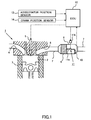
- Fig. 1 is a diagram showing a schematic structure of an internal combustion engine to which the present invention is applied and an exhaust system thereof.
- An internal combustion engine 1 shown in Fig. 1 is a compression ignition internal combustion engine (diesel engine).
- the internal combustion engine 1 includes cylinders 2.
- a piston 3 is slidably mounted in the cylinder.
- the internal combustion engine 1 comprises an intake port 4 for guiding new air (air) into the cylinder 2, a fuel injection valve 5 for injecting fuel into the cylinder 2, and an exhaust port 6 for discharging gas (burnt gas) from the cylinder 2.
- the exhaust port 6 is connected to an exhaust pipe 7.
- a casing 8 of the exhaust gas purification apparatus is provided at the middle of the exhaust pipe 7.
- a particulate filter 9, which traps particulate matter (PM) in the exhaust gas, is provided inside the casing 8.
- a PM sensor 10 is provided at the downstream of the particulate filter 9. The PM sensor 10 is a sensor which outputs an electric signal corresponding to a quantity of PM contained in the exhaust gas.
- a valve mechanism 11 is provided between the particulate filter 9 and the PM sensor 10 in the casing 8.
- the valve mechanism 11 includes a butterfly valve body 11 a and an actuator 11 b for changing an opening degree of the valve body 11 a.
- an ECU 12 is provided as an annex to the internal combustion engine 1.
- the ECU 12 is an electronic control unit comprising CPU, ROM, RAM, back-up RAM, etc.
- output signals from an accelerator position sensor 13 and a crank position sensor 14 are inputted into the ECU 12.
- the ECU 12 controls the fuel injection valve 5 and the actuator 11 b based on output signals from the above-mentioned various sensors.
- the ECU 12 performs controlling (fuel injection control) of a valve opening timing (fuel injection timing) of the fuel injection valve 5 and a period of time of valve opening (fuel injection quantity) of the fuel injection valve 5 by using output signals from the accelerator position sensor 13 and the crank position sensor 14, as parameters. Moreover, the ECU 12 executes the PM trapped quantity calculation process and the PM regeneration process which are the gist of the present invention, by using the output signal of the PM sensor 10 as the parameter.
- the ECU 12 calculates the quantity of PM trapped in the particulate filter 9 (PM trapped quantity) from the output signal of the PM sensor 10.
- the particulate filter 9 has the property that its PM trapping ability is increased when the PM trapped quantity is large, rather than when the PM trapped quantity is small. As a result, when the PM trapped quantity of the particulate filter 9 is large, the quantity of PM flowing out from the particulate filter 9 (hereinafter referred to as "the PM outflow quantity”) decreases in comparison to when the PM trapped quantity of the particulate filter 9 is small.
- the output signal (the PM outflow quantity) of the PM sensor 10 becomes a smaller value as shown in Fig. 2 , when the PM trapped quantity of the particulate filter 9 is large, rather than when it is small.
- the correlation as shown in Fig. 2 experimentally in advance it is possible to convert the output signal value of the PM sensor 10 into the PM trapped quantity. According to this method, the PM trapped quantity of the particulate filter 9 can be obtained more accurately.
- the starting time and the finishing time of the PM regeneration process can be determined based on the specified PM trapped quantity.
- the ECU 12 can start the PM regeneration process when the PM trapped quantity becomes equal to or exceeding the upper limit quantity. Further, the ECU 12 can finish the PM regeneration process when the PM trapped quantity, which is sought during the execution of the PM regeneration process, becomes equal to or less than the lower limit quantity.
- the above-mentioned upper limit quantity corresponds to the PM trapped quantity, for which it is thought that the magnitude of a back pressure caused by increase of the pressure loss of the particulate filter 9 exceeds the acceptable value.
- the above-mentioned lower limit quantity is the PM trapped quantity, for which it is thought that an interval between the PM regeneration process finishing time and the starting time of the next PM regeneration process does not become excessively short.
- the lower limit quantity is zero.
- the degree of increase of the PM trapped quantity while the PM regeneration process is not executed, or the degree of decrease of the PM trapped quantity while the PM regeneration process is executed may differ depending on the part of the particulate filter 9.
- the degree of change in the PM trapped quantity of the central portion and the degree of change in the PM trapped quantity of the peripheral portion may differ from one another.
- the PM regeneration process is carried out based on the PM trapped quantity of either at the central portion or the peripheral portion of the particulate filter 9, there may occur a situation where the PM quantity remaining in the particulate filter 9 at the time of finishing the PM regeneration process becomes excessive, or a situation where the PM regeneration process is continued even after the PM quantity remaining in the particulate filter has been decreased to less than the lower limit quantity.
- the ECU 12 calculates the PM trapped quantity at the central portion and the PM trapped quantity at the peripheral portion of the particulate filter 9 respectively, thereby to determine the starting timing and the finishing timing of the PM regeneration process based on these calculation results.
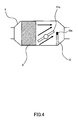
- a measuring part 10a of the PM sensor 10 is disposed on the path of the exhaust gas flowing out from the central portion of the particulate filter 9. That is, the measuring part 10a of the PM sensor 10 is located on a line extending from the central portion in the direction of the flow of the exhaust gas.
- the ECU 12 can calculate the quantity of PM trapped at the central portion of the particulate filter 9 (first trapped quantity), using a measured value of the PM sensor 10 at the time of fully open of the valve body 11 a, as the parameter.
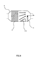
- the ECU 12 controls the valve mechanism 11 so that the valve body 11 a is caused to rotate counter-clockwise in Fig. 3 . At that time, the valve body 11 a is to rotate until the opening degree of the valve body 11 a becomes substantially parallel to the virtual straight line connecting the peripheral portion of the particulate filter 9 and the measuring part 10a (hereinafter will be called "the reference opening degree").
- the reference opening degree the opening degree of the valve body 11 a becomes substantially parallel to the virtual straight line connecting the peripheral portion of the particulate filter 9 and the measuring part 10a.
- the ECU 12 can calculate the second trapped quantity by using the measured value of the PM sensor 10 at the time when the opening degree of the valve body 11 a is made the reference opening degree, as the parameter.
- the second trapped quantity obtained by the above-mentioned method is the PM trapped quantity of a specified area (the area located in the lower part of Figs. 3 and 4 ) of the peripheral portion. Consequently, in the case where the PM trapped quantity of the entire area of the peripheral portion is specified, the second trapped quantity may be corrected based on a ratio (proportion) of the specified area to the entire area of the peripheral portion.
- a ratio proportion
- Fig. 5 is a flowchart showing a PM trapped quantity calculation process routine.
- This routine is a routine is stored in the ROM of the ECU 12 in advance, and executed at intervals by the ECU 12.
- the ECU 12 controls, in S101, the valve mechanism 11 so that the opening degree of the valve body 11a is fully opened.
- the opening degree of the valve body 11 a is preferably maintained fully opened, except the case where the second trapped quantity is obtained.
- the valve mechanism 11 also has the function as the known exhaust gas throttle valve.
- the ECU 12 reads the measured value of the PM sensor 10. Subsequently the ECU 12 proceeds to S103 where the ECU 12 calculates the first trapped quantity ⁇ PM1 from the measured value read in the S102 and the map as shown in Fig. 2 .
- the ECU 12 controls the valve mechanism 11 so that the opening degree of the valve body 11 a becomes the reference opening degree. Subsequently, the ECU proceeds to S105 where the ECU 12 reads the measured value of the PM sensor. In S106, the ECU 12 calculates the second trapped quantity ⁇ PM2 from the measured value read in the S105 and the above-mentioned map shown in Fig. 2 .
- the ECU 12 stores the first trapped quantity ⁇ PM1 and the second trapped quantity ⁇ PM2 calculated in the S103 and the S105 in the backup RAM.
- the ECU 12 controls the valve mechanism 11 so as to return the opening degree of the valve body 11 a to fully open.
- the calculation unit according to the present invention is implemented by the execution of the PM trapped quantity calculation process routine by the ECU12.
- the distribution of the PM trapped quantity in the radial direction of the particulate filter 9 in other words, the deviation between the PM trapped quantity at the central portion and the PM trapped quantity at the peripheral portion can be specified.
- the process of the S102 and the process of the S105 are preferably performed under the same engine operation state as much as possible. This is because the PM quantity discharged from the internal combustion engine 1 varies according to the engine operation state. Further, when the process of the S104 is executed, the back pressure acting on the internal combustion engine 1 rises. Because of this, it is preferable that the process of the S104 is performed at the time of low load operation state. Hence, the PM trapped quantity calculation process routine is executed when the internal combustion engine 1 is in the stationary operation state, preferably in the idling operation state.
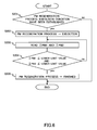
- Fig. 6 is a flowchart showing the PM regeneration process routine in the present embodiment. This routine is stored in the ROM of the ECU 12 in advance, and executed at intervals by the ECU12.
- the ECU 12 determines, in S201, whether or not the conditions for execution of the PM regeneration process have been established.
- the conditions for execution of the PM regeneration process the fact that the PM trapped quantity of the entire particulate filter 9 is equal to or more than the upper limit quantity may be exemplified.
- the PM regeneration process is executed under the condition that the above-stated first trapped quantity ⁇ PM1 is equal to or more than the upper limit quantity. This is due to the fact that the magnitude of the pressure loss of the particulate filter 9 mainly depends on the PM trapped quantity of the central portion.
- the ECU 12 reads the first trapped quantity ⁇ PM1 obtained by the above-mentioned PM trapped quantity calculation process routine, and determines whether the read out first trapped quantity ⁇ PM1 is equal to or more than the upper limit quantity.
- the ECU 12 executes the PM regeneration process.
- the ECU 12 raises the temperature of the particulate filter 9 up to the temperature region where the PM is oxidized.
- a method of raising the temperature of the particulate filter 9 a method of raising the temperature of the exhaust gas flowing into the particulate filter 9, or a method of generating heat of oxidation reaction in the particulate filter 9, may be used.
- a method which oxidizes the fuel in the exhaust gas, by injecting the fuel (secondary injection) from the fuel injection valve 5 during a period from the latter half of the expansion stroke to the first half of the exhaust stroke may be used.
- a method wherein an oxidization catalyst is disposed at the upstream of the particulate filter 9 thereby the fuel injected from the fuel injection valve 5 during the exhaust stroke is oxidized by the oxidization catalyst may be used.
- the reducing agent adding valve is disposed at the upstream of the oxidization catalyst, it is possible to use a method in which the reducing agent added into the exhaust gas from the reducing agent adding valve is oxidized in the oxidization catalyst.
- a method in which the particulate filter 9 carries thereon the oxidization catalyst, and the fuel or the reducing agent supplied to the exhaust gas from the fuel injection valve 5 or the reducing agent adding valve is oxidized in the particulate filter 9, may be used.
- the ECU 12 proceeds to S203.
- the ECU 12 reads out from the backup RAM the latest first trapped quantity ⁇ PM1 and the second trapped quantity ⁇ PM2 which were calculated by the PM trapped quantity calculation process routine.
- the ECU 12 determines whether or not the first trapped quantity ⁇ PM1 and the second trapped quantity ⁇ PM2 which were read out in the S203 are equal to or less than the lower limit quantity. When the negative determination is made in S204, the ECU 12 returns to S203. On the other hand, when the affirmative determination is made in S204, the ECU 12 proceeds to S205 where the ECU 12 terminates the PM regeneration process.
- the point of difference between the present embodiment and the above-described first embodiment is that the PM oxidization rate at the central portion and the PM oxidation rate at the peripheral portion of the particulate filter 9 are made uniform during the execution of the PM regeneration process in the present embodiment.
- Fig. 7 is a cross-sectional diagram showing a structure of an exhaust gas purification apparatus in a second embodiment.
- a cylindrical shape heater 90 is provided between the inner wall of the casing 8 and the outer wall of the particulate filter 9.
- the heater 90 heats the peripheral portion of the particulate filter 9 by, for example, converting the electric energy supplied from a battery (not shown) into the heat energy.
- the switching between an operation state and a non-operation state of the heater 90 is controlled by the ECU 12.
- Fig. 8 is a flowchart showing the PM regeneration process routine in the second embodiment.
- the same reference numerals are used for denoting the same processes as the PM regeneration process routine of the above-described first embodiment.
- the ECU 12 proceeds to S301 after having executed the process of S202.
- the ECU 12 calculates the decreasing rate v1 of the first trapped quantity ⁇ PM1 and the decreasing rate v2 of the second rapped quantity ⁇ PM2.
- the ECU 12 may use the above-mentioned difference ⁇ PM1 as a substitute value of the decreasing rate v1 of the first trapped quantity ⁇ PM1, and the ECU 12 may also use the above-mentioned difference ⁇ PM2 as a substitute value of the decreasing rate v2 of the second trapped quantity ⁇ PM2.
- the ECU 12 compares the decreasing rates v1 and v2 obtained in the S301. Specifically, the ECU 12 determines whether or not the decreasing rate v2 of the second trapped quantity ⁇ PM2 is lower than the decreasing rate v1 of the first trapped quantity ⁇ PM1.
- the ECU 12 proceeds to S303 to operate the heater 90. In that case, the temperature of the peripheral portion of the particulate filter 9 rises, thereby the PM oxidation rate at the peripheral portion is increased. As a result, the PM oxidation rate at the peripheral portion and the PM oxidation rate at the central portion become uniform.
- the ECU 12 proceeds to S304 to stop operation of the heater 90. Then, execution of the process of the S303 or the S304 has been finished, the ECU 12 executes the process of S203 and the subsequent processes.
- the PM oxidation rate at the central portion and the PM oxidation rate at the peripheral portion of the particulate filter 9 become substantially uniform. Consequently, the period of time of execution of the PM regeneration process can be shortened. Further, it is possible to avoid occurrence of the situation where the heater 90 is operated unnecessarily when the PM oxidation rate at the peripheral portion is equal to or greater than the PM oxidation rate at the central portion.
- valve mechanism 11 including the butterfly valve body 11 a was exemplified as the switching mechanism according to the present invention.
- any mechanism so long as it enables to perform measurement individually of the quantity of PM flowing out from the central portion and the quantity of PM flowing out from the peripheral portion of the particulate filter 9.
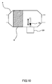
- a flap 110 which is rotatably supported on the inner wall surface of the casing 8, may be used.
- a driving mechanism 100 which displaces the measurement part 10a of the PM sensor 10 to be in parallel to the radial direction of the particulate filter 9, may be used.
- PM sensors may be disposed respectively on the path of the exhaust gas flowing out from the central portion and on the path of the exhaust gas flowing out from the peripheral portion of the particulate filter 9.
- the internal combustion engine of the compression ignition engine was exemplified as the internal combustion engine to which the present invention is applied, but the present invention can be applied also to the internal combustion engine of the spark ignition type (gasoline engine).
Landscapes
- Engineering & Computer Science (AREA)
- Chemical & Material Sciences (AREA)
- Analytical Chemistry (AREA)
- Combustion & Propulsion (AREA)
- Mechanical Engineering (AREA)
- General Engineering & Computer Science (AREA)
- Processes For Solid Components From Exhaust (AREA)
- Exhaust Gas After Treatment (AREA)
Abstract
Description
- The present invention relates to a technology for determining a quantity of particulate matter (PM) trapped in a particulate filter arranged in an exhaust system of an internal combustion engine.
- In the structure, in which the particulate filter is arranged in the exhaust system of the internal combustion engine, the technology is known such that when the quantity of the particulate matter (PM) trapped in the particulate filter exceeds a certain quantity, the particulate filter is heated, thereby the PM trapped in the particulate filter is oxidized and removed (PM regeneration process).
- For the method of determining whether or not the quantity of PM trapped in the particulate filter exceeds a certain quantity, there has been proposed a method which determines that the PM trapped quantity has exceeded a certain quantity when a differential pressure between the upstream and the downstream of the particulate filter (hereinafter will be referred to as the "fore-and-aft differential pressure") has exceeded a predetermined value (see, for example, the Patent Document 1).
-
- Patent Document 1: Japanese Patent Application Laid-Open Publication No.
2008-106698 - Patent Document 2: Japanese Patent Application Laid-Open Publication No.
2008-190470 - Patent Document 3: Japanese Patent Application Laid-Open Publication No.
2008-082199 - Patent Document 4: Japanese Patent Application Laid-Open Publication No.
08(1996)-028248 - Patent Document 5: Japanese Patent Application Laid-Open Publication No.
05(1993)-026029 - Patent Document 6: Japanese Patent Application Laid-Open Publication No.
2009-512814 - Patent Document 7: Japanese Patent Application Laid-Open Publication No.
2009-513870 - Patent Document 8: Japanese Patent Application Laid-Open Publication No.
2009-197718 - It should be noted that the above-mentioned fore-and-aft pressure varies according to a temperature and a flow rate of the exhaust gas. To deal with this, a method of correcting a detected value of the fore-and-aft differential pressure by using the exhaust gas temperature and the exhaust gas flow rate as parameters, can be considered. However, there may be a possibility that the correlation between the corrected fore-and-aft differential pressure and the actual PM trapped quantity becomes low.
- Further, the
Patent Document 2 proposes a method in which a PM sensor which detects a PM quantity flowing into the particulate filter is mounted on the exhaust system, and the PM trapped quantity of the particulate filter is obtained from a detected value of the PM sensor. However, there is a possibility that the PM trapped quantity differs between the central portion and the peripheral portion of the particulate filter in a radial direction thereof. Because of this, when the timing of the PM regeneration process is determined based on the detected value of the PM sensor, there may possibly occur such situation where the PM has not been removed but remains in the central portion or the peripheral portion of the particulate filter, or the situation where the PM regeneration process would be continued even after removing the PM. - The present invention has been made in view of the above-described various circumstances, and its object is to provide a technology that can specify the deviation in the PM trapped quantity between the central portion and the peripheral portion of the particulate filter in the radial direction thereof.
- In order to solve the above-described problems, the present invention is to measure a quantity of particulate matter (PM) contained in the exhaust gas flowing out from the central portion of the particular filter in the radial direction thereof and a quantity of PM contained in the exhaust gas flowing out from the peripheral portion of the particulate filter in the radial direction thereof, by a PM sensor, and the PM trapped quantity of the central portion and the PM tapped quantity of the peripheral portion are obtained from the results of these measurements.
- In detail, the exhaust gas purification system for an internal combustion engine of the present invention comprises:
- a particulate filter which is arranged in an exhaust passage of the internal combustion engine and traps particulate matter in an exhaust gas;
- a PM sensor which is arranged in the exhaust passage at the downstream of the particulate filter and measures a quantity of particulate matter contained in the exhaust gas;
- a switching mechanism for switching between a first mode in which the quantity of particulate matter contained in the exhaust gas flowing out from the central portion of the particulate filter in the radial direction thereof is measured by the PM sensor, and a second mode in which the quantity of particulate matter contained in the exhaust gas flowing out from the peripheral portion of the particulate filer in the radial direction thereof is measured by the PM sensor; and
- a calculation unit for calculating a first trapped quantity which is the PM trapped quantity of the central portion from the value measured by the PM sensor when the switching mechanism is in the first mode, and also calculating a second trapped quantity which is the PM trapped quantity of the peripheral portion from the value measured by the PM sensor when the switching mechanism is in the second mode.
- When the quantity of PM trapped in the particulate filter is large, the PM trapping ability of the particulate filter becomes high, as compared to when the quantity of PM trapped in the particulate filter is small. This is due to the fact that when the quantity of PM trapped in the particulate filer is large, a cross-sectional area of a flow passage in the particulate filter becomes small as compared to when the quantity of PM trapped in the particulate filter is small.
- According to the above-described characteristics, when the PM trapped quantity of the particulate filter is large, the quantity of PM flowing out from the particulate filter (namely, the quantity of PM that passes through the filter) is small as compared to when the PM trapped quantity is small. Consequently, when the PM quantity detected by the PM sensor is small, it means that the PM trapped quantity of the particulate filer is large, as compared to when the PM quantity detected by the PM sensor is large. Thereby, the PM trapped quantity of the particulate filter can be calculated from the value detected by the PM sensor.
- Further, according to the present invention, the quantity of PM flowing out from the central portion of the particulate filer in the radial direction thereof, and the quantity of PM flowing out from the peripheral portion of the particulate filter in the radial direction thereof, can be detected individually. As a result, the PM trapped quantity of the central portion (first trapped quantity) and the PM trapped quantity of the peripheral portion (second trapped quantity) can be specified, respectively.
- When the first trapped quantity and the second trapped quantity are specified respectively, the PM trapped in the central portion and the PM trapped in the peripheral portion can be oxidized and removed properly, that is, neither too much nor too little. For example, the exhaust gas purification system for the internal combustion engine of the present invention may further comprises a regeneration processing unit for performing a PM regeneration process which is the process of raising the temperature of the particulate filter for oxidizing and removing the PM trapped in the particulate filter. And, the regeneration processing unit may finish the PM regeneration process when the first trapped quantity and the second trapped quantity becomes equal to or less than a target quantity. The target quantity is a quantity determined by the specifications of the internal combustion engine and the specifications of the particulate filter. Such the target quantity may be zero or a value which is larger than zero.
- When the PM regeneration process is executed by such method, it is possible to avoid a situation where the quantity of PM un-oxidized at the central portion or the peripheral portion of the particulate filter becomes large, and a situation where the PM regeneration process will be continued even after the first trapped quantity and the second trapped quantity become equal to or less than the target quantity. As a result, the PM trapped at the central portion and the peripheral portion can be oxidized and removed properly.
- Further, the exhaust gas purification system for the internal combustion engine of the present invention may further comprises a regeneration processing unit for performing the PM regeneration process which is the process of raising the temperature of the particulate filter in order to oxidize and remove the PM trapped in the particulate filter, and a heater for heating the peripheral portion locally. And, if a decreasing rate of the second trapped quantity is low as compared to a decreasing rate of the first trapped quantity during execution of the PM regeneration process, the heater may be operated.
- When the heater is controlled in this manner, an oxidation rate of the PM at the central portion and an oxidation rate of the PM at the peripheral portion become substantially uniform. Thus, a period of time of execution of the PM regeneration process can be shortened. Further, it is possible to avoid a situation where the heater is operated unnecessarily when the PM oxidation rate at the peripheral portion is equal to or greater than the PM oxidation rate at the central portion.
- Even when the decreasing rate of the second trapped quantity is low with respect to the decreasing rate of the first trapped quantity, the heater may be adapted to be not operated if the second trapped quantity is less than the first trapped quantity. Preferably, the heater may be adapted to be not operated even when the decreasing rate of the second trapped quantity is low with respect to the decreasing rate of the first trapped quantity, if the regeneration at the periphery portion is predicted to be finished by the time of finishing the regeneration at the central portion. When the heater is controlled in this manner, the PM trapped at the central portion and the peripheral portion can be oxidized and removed, without operating the heater unnecessarily.
- Here, as a method for predicting whether or not the regeneration of the peripheral portion will finish by the time of finishing the regeneration of the central portion, the regeneration finishing time (or a period of time required for regeneration) at the central portion is calculated from the PM oxidation rate at the central portion and the first trapped quantity, and also the regeneration finishing time (or a period of time required for regeneration) at the peripheral portion is calculated from the PM oxidation rate at the peripheral portion and the second trapped quantity, and to compare these calculations.
- In the present invention, for the switching mechanism, a mechanism, which switches between a mode wherein the flow of the exhaust gas flowing out from the central portion is directed to the PM sensor, and a mode wherein the flow of the exhaust gas flowing out from the peripheral portion is directed to the PM sensor, may be used. For such a switching mechanism, a valve mechanism having a butterfly type valve body, may be used. In that case, when the state of the valve body is in parallel to a virtual straight line connecting the central portion of the particulate filter and the PM sensor, the exhaust gas flowing out from the central portion is led to the PM sensor by the valve body. Further, when the state of the valve body is in parallel to a virtual straight line connecting the peripheral portion of the particulate filter and the PM sensor, the exhaust gas flowing out from the peripheral portion is lead to the PM sensor by the valve body. By switching the state of the valve body in this manner, the first trapped quantity and the second trapped quantity can be obtained by a single PM sensor.
- When the valve body is parallel to the virtual line connecting the central portion of the particulate filter with the PM sensor or when the valve body is parallel to the virtual line connecting the peripheral portion of the particulate filter with the PM sensor, the PM sensor may be arranged so that the degree of opening of the valve body is fully open. In this case, the valve body is fully open either in the first mode or in the second mode, increase of a pressure loss caused by providing the valve body can be kept to a minimum.
- Further, for the switching mechanism of the present invention, a mechanism which changes the position of the PM sensor may be used. In more detail, the switching mechanism may be a mechanism which switches between a mode wherein the PM sensor is moved onto the path of the exhaust gas flowing out from the central portion, and a mode wherein the PM sensor is moved onto the path of the exhaust gas flowing out from the peripheral portion.
- According to the present invention, it is possible to accurately obtain the PM trapped quantity of the particulate filter arranged in the exhaust system of the internal combustion engine
-
-
Fig. 1 is a diagram showing a schematic structure of an internal combustion engine to which the present invention is applied and an exhaust system thereof. -
Fig. 2 is a diagram showing the relationship between the PM trapped quantity of the particulate filter and the PM outflow quantity. -
Fig. 3 is a diagram showing a state of a valve body when detecting the quantity of PM flowing out from the central portion of the particulate filter. -
Fig. 4 is a diagram showing a state of the valve body when detecting the quantity of PM flowing out from the peripheral portion of the particulate filter. -
Fig. 5 is a flowchart showing a PM trapped quantity calculation process routine in a first embodiment. -
Fig. 6 is a flowchart showing a PM regeneration process routine in the first embodiment. -
Fig. 7 is a diagram showing a structure of an exhaust gas purification apparatus in a second embodiment. -
Fig. 8 is a flowchart showing the PM regeneration process routine in the second embodiment. -
Fig. 9 is a diagram showing another structural example of the switching mechanism according to the present invention. -
Fig. 10 is a diagram showing still another structural example of the switching mechanism according to the present invention. - Hereinafter, a description will be made of specific embodiments of the present invention with reference to the accompanying drawings. Regarding the dimensions, materials, shapes and relative arrangements, etc. of the components to be described in the embodiments are not intended to limit the technical scope of the present invention unless specifically described.
- First, a description will be made of a first embodiment of the present invention based on
Fig. 1 to Fig. 6 .Fig. 1 is a diagram showing a schematic structure of an internal combustion engine to which the present invention is applied and an exhaust system thereof. Aninternal combustion engine 1 shown inFig. 1 is a compression ignition internal combustion engine (diesel engine). - The
internal combustion engine 1 includescylinders 2. Apiston 3 is slidably mounted in the cylinder. Theinternal combustion engine 1 comprises anintake port 4 for guiding new air (air) into thecylinder 2, a fuel injection valve 5 for injecting fuel into thecylinder 2, and anexhaust port 6 for discharging gas (burnt gas) from thecylinder 2. Theexhaust port 6 is connected to anexhaust pipe 7. - A
casing 8 of the exhaust gas purification apparatus is provided at the middle of theexhaust pipe 7. Aparticulate filter 9, which traps particulate matter (PM) in the exhaust gas, is provided inside thecasing 8. Inside thecasing 8, aPM sensor 10 is provided at the downstream of theparticulate filter 9. ThePM sensor 10 is a sensor which outputs an electric signal corresponding to a quantity of PM contained in the exhaust gas. - A
valve mechanism 11 is provided between theparticulate filter 9 and thePM sensor 10 in thecasing 8. Thevalve mechanism 11 includes abutterfly valve body 11 a and anactuator 11 b for changing an opening degree of thevalve body 11 a. - Further, an
ECU 12 is provided as an annex to theinternal combustion engine 1. TheECU 12 is an electronic control unit comprising CPU, ROM, RAM, back-up RAM, etc. In addition to the above-mentionedPM sensor 10, output signals from anaccelerator position sensor 13 and a crankposition sensor 14 are inputted into theECU 12. TheECU 12 controls the fuel injection valve 5 and theactuator 11 b based on output signals from the above-mentioned various sensors. - For example, the
ECU 12 performs controlling (fuel injection control) of a valve opening timing (fuel injection timing) of the fuel injection valve 5 and a period of time of valve opening (fuel injection quantity) of the fuel injection valve 5 by using output signals from theaccelerator position sensor 13 and the crankposition sensor 14, as parameters. Moreover, theECU 12 executes the PM trapped quantity calculation process and the PM regeneration process which are the gist of the present invention, by using the output signal of thePM sensor 10 as the parameter. - Hereinafter, a description will be made of the PM trapped quantity calculation process and the PM regeneration process in the present embodiment. First, in the PM trapped quantity calculation process, the
ECU 12 calculates the quantity of PM trapped in the particulate filter 9 (PM trapped quantity) from the output signal of thePM sensor 10. - Here, the
particulate filter 9 has the property that its PM trapping ability is increased when the PM trapped quantity is large, rather than when the PM trapped quantity is small. As a result, when the PM trapped quantity of theparticulate filter 9 is large, the quantity of PM flowing out from the particulate filter 9 (hereinafter referred to as "the PM outflow quantity") decreases in comparison to when the PM trapped quantity of theparticulate filter 9 is small. - Accordingly, the output signal (the PM outflow quantity) of the
PM sensor 10 becomes a smaller value as shown inFig. 2 , when the PM trapped quantity of theparticulate filter 9 is large, rather than when it is small. Hence, by obtaining the correlation as shown inFig. 2 experimentally in advance, it is possible to convert the output signal value of thePM sensor 10 into the PM trapped quantity. According to this method, the PM trapped quantity of theparticulate filter 9 can be obtained more accurately. - When the PM trapped quantity of the
particulate filter 9 is specified, the starting time and the finishing time of the PM regeneration process can be determined based on the specified PM trapped quantity. For example, theECU 12 can start the PM regeneration process when the PM trapped quantity becomes equal to or exceeding the upper limit quantity. Further, theECU 12 can finish the PM regeneration process when the PM trapped quantity, which is sought during the execution of the PM regeneration process, becomes equal to or less than the lower limit quantity. - Note that the above-mentioned upper limit quantity corresponds to the PM trapped quantity, for which it is thought that the magnitude of a back pressure caused by increase of the pressure loss of the
particulate filter 9 exceeds the acceptable value. Further, the above-mentioned lower limit quantity is the PM trapped quantity, for which it is thought that an interval between the PM regeneration process finishing time and the starting time of the next PM regeneration process does not become excessively short. Preferably, the lower limit quantity is zero. - Note that there may be a case where the degree of increase of the PM trapped quantity while the PM regeneration process is not executed, or the degree of decrease of the PM trapped quantity while the PM regeneration process is executed, may differ depending on the part of the
particulate filter 9. For example, in the radial direction of theparticulate filter 9, the degree of change in the PM trapped quantity of the central portion and the degree of change in the PM trapped quantity of the peripheral portion may differ from one another. - In the above-mentioned case, if the PM regeneration process is carried out based on the PM trapped quantity of either at the central portion or the peripheral portion of the
particulate filter 9, there may occur a situation where the PM quantity remaining in theparticulate filter 9 at the time of finishing the PM regeneration process becomes excessive, or a situation where the PM regeneration process is continued even after the PM quantity remaining in the particulate filter has been decreased to less than the lower limit quantity. - Thus, in the PM trapped quantity calculation process of the present embodiment, the
ECU 12 calculates the PM trapped quantity at the central portion and the PM trapped quantity at the peripheral portion of theparticulate filter 9 respectively, thereby to determine the starting timing and the finishing timing of the PM regeneration process based on these calculation results. - Here, a method of obtaining the PM trapped quantity at the central portion and the PM trapped quantity at the peripheral portion of the
particulate filter 9 will be described, based onFigs. 3 and4 . A measuringpart 10a of thePM sensor 10 is disposed on the path of the exhaust gas flowing out from the central portion of theparticulate filter 9. That is, the measuringpart 10a of thePM sensor 10 is located on a line extending from the central portion in the direction of the flow of the exhaust gas. - According to this arrangement, when the
valve body 11 a of thevalve mechanism 11 is fully opened (when thevalve body 11 a is parallel to the direction of the flow of the exhaust gas flowing out from the particulate filter 9), the exhaust gas flowing out from the central portion of theparticulate filter 9 is to flow via the measuringpart 10a of thePM sensor 10, as shown inFig. 3 . Hence, theECU 12 can calculate the quantity of PM trapped at the central portion of the particulate filter 9 (first trapped quantity), using a measured value of thePM sensor 10 at the time of fully open of thevalve body 11 a, as the parameter. - Further, in the case where the quantity of PM trapped at the peripheral portion of the particulate filter 9 (second trapped quantity) is obtained, the
ECU 12 controls thevalve mechanism 11 so that thevalve body 11 a is caused to rotate counter-clockwise inFig. 3 . At that time, thevalve body 11 a is to rotate until the opening degree of thevalve body 11 a becomes substantially parallel to the virtual straight line connecting the peripheral portion of theparticulate filter 9 and the measuringpart 10a (hereinafter will be called "the reference opening degree"). When thevalve mechanism 11 is controlled in this manner, the exhaust gas flowing out from the peripheral portion of theparticulate filter 9 is to flow via the measuringpart 10a of thePM sensor 10. Hence, theECU 12 can calculate the second trapped quantity by using the measured value of thePM sensor 10 at the time when the opening degree of thevalve body 11 a is made the reference opening degree, as the parameter. - Note that the second trapped quantity obtained by the above-mentioned method is the PM trapped quantity of a specified area (the area located in the lower part of
Figs. 3 and4 ) of the peripheral portion. Consequently, in the case where the PM trapped quantity of the entire area of the peripheral portion is specified, the second trapped quantity may be corrected based on a ratio (proportion) of the specified area to the entire area of the peripheral portion. However, with the present embodiment, it is sufficient that a relative relation (ratio or deviation) between the PM trapped quantity at the central portion and the PM trapped quantity at the peripheral portion is specified. Hence, there is no need to obtain the PM trapped quantity of the entire area of the peripheral portion. - Here, procedures for obtaining the PM trapped quantity at the central portion and the PM trapped quantity at the peripheral portion of the
particulate filter 9 will be described with reference toFig. 5. Fig. 5 is a flowchart showing a PM trapped quantity calculation process routine. This routine is a routine is stored in the ROM of theECU 12 in advance, and executed at intervals by theECU 12. - Firstly, in the PM trapped quantity calculation process routine, the
ECU 12 controls, in S101, thevalve mechanism 11 so that the opening degree of thevalve body 11a is fully opened. Note that the opening degree of thevalve body 11 a is preferably maintained fully opened, except the case where the second trapped quantity is obtained. However, this is not a limitation to the case where thevalve mechanism 11 also has the function as the known exhaust gas throttle valve. - In S102, the
ECU 12 reads the measured value of thePM sensor 10. Subsequently theECU 12 proceeds to S103 where theECU 12 calculates the first trapped quantity ΣPM1 from the measured value read in the S102 and the map as shown inFig. 2 . - In S104, the
ECU 12 controls thevalve mechanism 11 so that the opening degree of thevalve body 11 a becomes the reference opening degree. Subsequently, the ECU proceeds to S105 where theECU 12 reads the measured value of the PM sensor. In S106, theECU 12 calculates the second trapped quantity ΣPM2 from the measured value read in the S105 and the above-mentioned map shown inFig. 2 . - In S107, the
ECU 12 stores the first trapped quantity ΣPM1 and the second trapped quantity ΣPM2 calculated in the S103 and the S105 in the backup RAM. In S108, theECU 12 controls thevalve mechanism 11 so as to return the opening degree of thevalve body 11 a to fully open. - As described above, the calculation unit according to the present invention is implemented by the execution of the PM trapped quantity calculation process routine by the ECU12. As result, the distribution of the PM trapped quantity in the radial direction of the
particulate filter 9, in other words, the deviation between the PM trapped quantity at the central portion and the PM trapped quantity at the peripheral portion can be specified. - Also, the process of the S102 and the process of the S105 are preferably performed under the same engine operation state as much as possible. This is because the PM quantity discharged from the
internal combustion engine 1 varies according to the engine operation state. Further, when the process of the S104 is executed, the back pressure acting on theinternal combustion engine 1 rises. Because of this, it is preferable that the process of the S104 is performed at the time of low load operation state. Hence, the PM trapped quantity calculation process routine is executed when theinternal combustion engine 1 is in the stationary operation state, preferably in the idling operation state. - Next, procedures for execution of the PM regeneration process will be described with reference to
Fig. 6. Fig. 6 is a flowchart showing the PM regeneration process routine in the present embodiment. This routine is stored in the ROM of theECU 12 in advance, and executed at intervals by the ECU12. - Firstly, in the PM regeneration process routine, the
ECU 12 determines, in S201, whether or not the conditions for execution of the PM regeneration process have been established. As the conditions for execution of the PM regeneration process, the fact that the PM trapped quantity of the entireparticulate filter 9 is equal to or more than the upper limit quantity may be exemplified. However, with the present embodiment, the PM regeneration process is executed under the condition that the above-stated first trapped quantity ΣPM1 is equal to or more than the upper limit quantity. This is due to the fact that the magnitude of the pressure loss of theparticulate filter 9 mainly depends on the PM trapped quantity of the central portion. Hence, theECU 12 reads the first trapped quantity ΣPM1 obtained by the above-mentioned PM trapped quantity calculation process routine, and determines whether the read out first trapped quantity ΣPM1 is equal to or more than the upper limit quantity. - When the negative determination is made in the S201, the
ECU 12 terminates temporarily the execution of this routine. On the other hand, when the affirmative determination is made in the S201, theECU 12 proceeds to S202. - In S202, the
ECU 12 executes the PM regeneration process. In detail, theECU 12 raises the temperature of theparticulate filter 9 up to the temperature region where the PM is oxidized. For the method of raising the temperature of theparticulate filter 9, a method of raising the temperature of the exhaust gas flowing into theparticulate filter 9, or a method of generating heat of oxidation reaction in theparticulate filter 9, may be used. - For the method of raising the temperature of the exhaust gas, a method which oxidizes the fuel in the exhaust gas, by injecting the fuel (secondary injection) from the fuel injection valve 5 during a period from the latter half of the expansion stroke to the first half of the exhaust stroke, may be used. For the other method of raising the temperature of the exhaust gas, a method wherein an oxidization catalyst is disposed at the upstream of the
particulate filter 9 thereby the fuel injected from the fuel injection valve 5 during the exhaust stroke is oxidized by the oxidization catalyst, may be used. Note that, in the case where the reducing agent adding valve is disposed at the upstream of the oxidization catalyst, it is possible to use a method in which the reducing agent added into the exhaust gas from the reducing agent adding valve is oxidized in the oxidization catalyst. - For the method of generating heat of oxidation reaction in the
particulate filer 9, a method in which theparticulate filter 9 carries thereon the oxidization catalyst, and the fuel or the reducing agent supplied to the exhaust gas from the fuel injection valve 5 or the reducing agent adding valve is oxidized in theparticulate filter 9, may be used. - When the process of S202 is executed using the above-mentioned various methods, the
ECU 12 proceeds to S203. In S203, theECU 12 reads out from the backup RAM the latest first trapped quantity ΣPM1 and the second trapped quantity ΣPM2 which were calculated by the PM trapped quantity calculation process routine. - In S204, the
ECU 12 determines whether or not the first trapped quantity ΣPM1 and the second trapped quantity ΣPM2 which were read out in the S203 are equal to or less than the lower limit quantity. When the negative determination is made in S204, theECU 12 returns to S203. On the other hand, when the affirmative determination is made in S204, theECU 12 proceeds to S205 where theECU 12 terminates the PM regeneration process. - When the PM regeneration process of the
particulate filter 9 is executed according to the PM regeneration process routine in such manner as described above, occurrence of the situation in which the PM quantity remaining at the central portion or at the peripheral portion is excessive at the time of termination of the PM regeneration process, and occurrence of the situation in which the PM regeneration process is continued even after the PM quantity remaining in theparticulate filter 9 has been decreased to equal to or less than the lower limit quantity, can be avoided. - Next, a second embodiment of the present invention will be described based on
Fig. 7 andFig. 8 .
Here, a description will be made of the structures which are different from that of the above-described first embodiment, and regarding the same structures, the description will be omitted. - The point of difference between the present embodiment and the above-described first embodiment is that the PM oxidization rate at the central portion and the PM oxidation rate at the peripheral portion of the
particulate filter 9 are made uniform during the execution of the PM regeneration process in the present embodiment. -
Fig. 7 is a cross-sectional diagram showing a structure of an exhaust gas purification apparatus in a second embodiment. InFig. 7 , acylindrical shape heater 90 is provided between the inner wall of thecasing 8 and the outer wall of theparticulate filter 9. Theheater 90 heats the peripheral portion of theparticulate filter 9 by, for example, converting the electric energy supplied from a battery (not shown) into the heat energy. The switching between an operation state and a non-operation state of theheater 90 is controlled by theECU 12. -
Fig. 8 is a flowchart showing the PM regeneration process routine in the second embodiment. The same reference numerals are used for denoting the same processes as the PM regeneration process routine of the above-described first embodiment. - In the PM regeneration process routine of
Fig. 8 , theECU 12 proceeds to S301 after having executed the process of S202. In S301, theECU 12 calculates the decreasing rate v1 of the first trapped quantity ΣPM1 and the decreasing rate v2 of the second rapped quantity ΣPM2. - For example, the
ECU 12 obtains the decreasing rate v1 of the first trapped quantity ΣPM1 by dividing the difference ΣPM1 (= ΣPM1old - ΣPM1) between the latest first trapped quantity ΣPM1 obtained in the PM trapped quantity calculation process routine and the previously obtained first trapped quantity ΣPM1old by the execution interval t of the PM trapped quantity calculation process routine, that is, v1 (= ΔΣPM1/t). - Similarly, the
ECU 12 obtains the decreasing rate v2 of the second trapped quantity ΣPM2 by dividing the difference ΔΣPM2 (= ΣPM2old - ΣPM2) between the latest second trapped quantity ΣPM21 obtained in the PM trapped quantity calculation process routine and the previously obtained second trapped quantity ΣPM2old by the execution interval t, that is, v2 (= ΔΣPM2/t). - Note that the
ECU 12 may use the above-mentioned difference ΔΣPM1 as a substitute value of the decreasing rate v1 of the first trapped quantity ΣPM1, and theECU 12 may also use the above-mentioned difference ΔΣPM2 as a substitute value of the decreasing rate v2 of the second trapped quantity ΣPM2. - In S302, the
ECU 12 compares the decreasing rates v1 and v2 obtained in the S301. Specifically, theECU 12 determines whether or not the decreasing rate v2 of the second trapped quantity ΣPM2 is lower than the decreasing rate v1 of the first trapped quantity ΣPM1. - When the affirmative determination (v2 < v1) is made in the S302, the
ECU 12 proceeds to S303 to operate theheater 90. In that case, the temperature of the peripheral portion of theparticulate filter 9 rises, thereby the PM oxidation rate at the peripheral portion is increased. As a result, the PM oxidation rate at the peripheral portion and the PM oxidation rate at the central portion become uniform. On the other hand, when the negative determination (v2 ≥ v1) is made in the S303, theECU 12 proceeds to S304 to stop operation of theheater 90. Then, execution of the process of the S303 or the S304 has been finished, theECU 12 executes the process of S203 and the subsequent processes. - When the PM regeneration process is executed according to the PM oxidation process routine in such manner as described above, the PM oxidation rate at the central portion and the PM oxidation rate at the peripheral portion of the
particulate filter 9 become substantially uniform. Consequently, the period of time of execution of the PM regeneration process can be shortened. Further, it is possible to avoid occurrence of the situation where theheater 90 is operated unnecessarily when the PM oxidation rate at the peripheral portion is equal to or greater than the PM oxidation rate at the central portion. - With the above-described first and the second embodiments, the
valve mechanism 11 including thebutterfly valve body 11 a was exemplified as the switching mechanism according to the present invention. However, any mechanism, so long as it enables to perform measurement individually of the quantity of PM flowing out from the central portion and the quantity of PM flowing out from the peripheral portion of theparticulate filter 9. - For example, as shown in
Fig. 9 , aflap 110 which is rotatably supported on the inner wall surface of thecasing 8, may be used. Further, as shown inFig. 10 , adriving mechanism 100 which displaces themeasurement part 10a of thePM sensor 10 to be in parallel to the radial direction of theparticulate filter 9, may be used. Still further, PM sensors may be disposed respectively on the path of the exhaust gas flowing out from the central portion and on the path of the exhaust gas flowing out from the peripheral portion of theparticulate filter 9. - Moreover, with the above-described first and the second embodiments, the internal combustion engine of the compression ignition engine was exemplified as the internal combustion engine to which the present invention is applied, but the present invention can be applied also to the internal combustion engine of the spark ignition type (gasoline engine).
-
- 1.
- internal combustion engine
- 2.
- cylinder
- 3.
- piston
- 4.
- intake port
- 5.
- fuel injection valve
- 6.
- exhaust port
- 7.
- exhaust pipe
- 8.
- casing
- 9.
- particulate filter
- 10.
- PM sensor
- 10a
- measurement part
- 11.
- valve mechanism
- 11a
- valve body
- 11b
- actuator
- 13.
- accelerator position sensor
- 14.
- crank position sensor
- 90.
- heater
- 100.
- driving mechanism
- 110.
- flap
Claims (7)
- An exhaust gas purification system for an internal combustion engine comprising:a particulate filter which is arranged in an exhaust passage of the internal combustion engine and traps particulate matter in an exhaust gas;a PM sensor which is arranged in the exhaust passage at the downstream of the particulate filter and measures a quantity of particulate matter contained in the exhaust gas;switching mechanism for switching between a first mode in which the quantity of particulate matter contained in the exhaust gas flowing out from the central portion of the particulate filter in the radial direction thereof is measured by the PM sensor and a second mode in which the quantity of particulate matter contained in the exhaust gas flowing out from the peripheral portion of the particulate filer in the radial direction thereof is measured by the PM sensor; anda calculation unit for calculating a first trapped quantity which is the PM trapped quantity of the central portion from the value measured by the PM sensor when the switching mechanism is in the first mode, and also calculating a second trapped quantity which is the PM trapped quantity of the peripheral portion from the value measured by the PM sensor when the switching mechanism is in the second mode.
- The exhaust gas purification system according to claim 1,
wherein the switching mechanism is arranged in the exhaust passage at the downstream of the particulate filter and at the upstream of the PM sensor, and switches between a first mode where the flow of the exhaust gas flowing out from the central portion is directed to the PM sensor and a second mode where the flow of the exhaust gas flowing out from the peripheral portion is directed to the PM sensor. - The exhaust gas purification system according to claim 2,
wherein the switching mechanism is equipped with a butterfly valve body, and adjust an opening degree of the valve body so that in the first mode the valve body is in parallel to a virtual straight line connecting the central portion and the PM sensor, and adjust the opening degree of the valve body so that in the second mode the valve body is in parallel to a virtual straight line connecting the peripheral portion and the PM sensor. - The exhaust gas purification system according to claim 3,
wherein the PM sensor is arranged so that the valve body is fully open when the valve body is parallel to the virtual straight line connecting the central portion and the PM sensor, or when the said valve body is parallel to the virtual straight line connecting the peripheral portion and the PM sensor. - The exhaust gas purification system according to claim 1,
wherein the switching mechanism is a mechanism that switches between a first mode where the PM sensor is moved onto a path of the exhaust gas flowing out from the central portion, and a second mode where the PM sensor is moved onto a path of the exhaust gas flowing out from the peripheral portion. - The exhaust gas purification system according to any one of claims 1 to 5, further comprising:a regeneration processing unit for performing a PM regeneration process which is a process of raising a temperature of the particulate filter for oxidizing and removing the particulate matter trapped in the particulate filter;wherein the regeneration processing unit finishes the PM regeneration process when the first trapped quantity and the second trapped quantity become equal to or less than a predetermined target quantity.
- The exhaust gas purification system according to claim 4, further comprising:a heater which heats the peripheral portion locally;wherein the regeneration processing unit operates the heater when a decreasing rate of the second trapped quantity is small with respect to a decreasing rate of the first trapped quantity, during the execution of the PM regeneration process.
Applications Claiming Priority (1)
| Application Number | Priority Date | Filing Date | Title |
|---|---|---|---|
| PCT/JP2010/056323 WO2011125192A1 (en) | 2010-04-07 | 2010-04-07 | Exhaust gas purification system for internal combustion engine |
Publications (4)
| Publication Number | Publication Date |
|---|---|
| EP2557283A1 true EP2557283A1 (en) | 2013-02-13 |
| EP2557283A8 EP2557283A8 (en) | 2013-04-10 |
| EP2557283A4 EP2557283A4 (en) | 2014-04-23 |
| EP2557283B1 EP2557283B1 (en) | 2015-09-23 |
Family
ID=44762178
Family Applications (1)
| Application Number | Title | Priority Date | Filing Date |
|---|---|---|---|
| EP10849436.0A Not-in-force EP2557283B1 (en) | 2010-04-07 | 2010-04-07 | Exhaust gas purification system for internal combustion engine |
Country Status (3)
| Country | Link |
|---|---|
| EP (1) | EP2557283B1 (en) |
| JP (1) | JP5360293B2 (en) |
| WO (1) | WO2011125192A1 (en) |
Cited By (2)
| Publication number | Priority date | Publication date | Assignee | Title |
|---|---|---|---|---|
| FR3007454A1 (en) * | 2013-06-24 | 2014-12-26 | Peugeot Citroen Automobiles Sa | EXHAUST SYSTEM FOR INTERNAL COMBUSTION ENGINE OF MOTOR VEHICLE |
| CN109989812A (en) * | 2017-11-24 | 2019-07-09 | 铃木株式会社 | The arrangement and emission control of Abgassensor |
Families Citing this family (2)
| Publication number | Priority date | Publication date | Assignee | Title |
|---|---|---|---|---|
| CN106150636B (en) * | 2016-08-26 | 2018-06-22 | 广西玉柴机器股份有限公司 | A kind of device for improving sensor measurement accuracy |
| FR3130882B1 (en) * | 2021-12-21 | 2025-05-30 | Renault Sas | Internal combustion engine unit comprising an exhaust circuit with a nitrogen oxide concentration sensor |
Family Cites Families (11)
| Publication number | Priority date | Publication date | Assignee | Title |
|---|---|---|---|---|
| JPH0526029A (en) | 1991-07-22 | 1993-02-02 | Toyota Motor Corp | Exhaust gas purification device for internal combustion engine |
| JP3589308B2 (en) | 1994-07-14 | 2004-11-17 | イビデン株式会社 | Exhaust gas purification device |
| JPH08296426A (en) * | 1995-04-24 | 1996-11-12 | Nippondenso Co Ltd | Exhaust particulates purifying device |
| US7765792B2 (en) | 2005-10-21 | 2010-08-03 | Honeywell International Inc. | System for particulate matter sensor signal processing |
| FR2892641B1 (en) | 2005-10-27 | 2008-07-11 | Saint Gobain Ct Recherches | MEASURING THE HOMOGENICITY OF DEPOSITING SOIL IN A PARTICLE FILTER AND CONTROLLING THE REGENERATION OF SAID FILTER |
| JP2008082199A (en) | 2006-09-26 | 2008-04-10 | Toyota Motor Corp | Exhaust gas purification device for internal combustion engine |
| JP4844349B2 (en) | 2006-10-26 | 2011-12-28 | トヨタ自動車株式会社 | Exhaust gas purification system for internal combustion engine |
| JP2008190470A (en) | 2007-02-06 | 2008-08-21 | Nissan Motor Co Ltd | Exhaust purification filter regeneration device |
| JP2008261322A (en) * | 2007-04-13 | 2008-10-30 | Toyota Motor Corp | The present invention relates to an exhaust particulate measurement device for an internal combustion engine. |
| JP2009041417A (en) * | 2007-08-08 | 2009-02-26 | Mazda Motor Corp | Particulate collector failure diagnosis device |
| JP2009197718A (en) | 2008-02-22 | 2009-09-03 | Toyota Motor Corp | Exhaust emission control device of internal combustion engine |
-
2010
- 2010-04-07 EP EP10849436.0A patent/EP2557283B1/en not_active Not-in-force
- 2010-04-07 JP JP2012509237A patent/JP5360293B2/en not_active Expired - Fee Related
- 2010-04-07 WO PCT/JP2010/056323 patent/WO2011125192A1/en not_active Ceased
Non-Patent Citations (2)
| Title |
|---|
| No further relevant documents disclosed * |
| See also references of WO2011125192A1 * |
Cited By (3)
| Publication number | Priority date | Publication date | Assignee | Title |
|---|---|---|---|---|
| FR3007454A1 (en) * | 2013-06-24 | 2014-12-26 | Peugeot Citroen Automobiles Sa | EXHAUST SYSTEM FOR INTERNAL COMBUSTION ENGINE OF MOTOR VEHICLE |
| CN109989812A (en) * | 2017-11-24 | 2019-07-09 | 铃木株式会社 | The arrangement and emission control of Abgassensor |
| DE102018220131B4 (en) | 2017-11-24 | 2024-03-14 | Suzuki Motor Corporation | Exhaust gas sensor arrangement structure and exhaust gas control system |
Also Published As
| Publication number | Publication date |
|---|---|
| EP2557283A8 (en) | 2013-04-10 |
| EP2557283B1 (en) | 2015-09-23 |
| JPWO2011125192A1 (en) | 2013-07-08 |
| WO2011125192A1 (en) | 2011-10-13 |
| EP2557283A4 (en) | 2014-04-23 |
| JP5360293B2 (en) | 2013-12-04 |
Similar Documents
| Publication | Publication Date | Title |
|---|---|---|
| EP1882088B1 (en) | Exhaust gas purification system for internal combustion engine | |
| CN101578435B (en) | Catalyst aging diagnostic device | |
| EP1544432B1 (en) | Regeneration control of diesel particulate filter | |
| US8845783B2 (en) | Failure detection apparatus and failure detection method for a particulate filter | |
| JP2005315198A (en) | Exhaust gas purification device for internal combustion engine | |
| US10125707B2 (en) | Control apparatus for exhaust gas purification system | |
| JP5168089B2 (en) | Catalyst diagnostic device | |
| JP2008267178A (en) | Exhaust gas purification device for internal combustion engine | |
| KR101034020B1 (en) | CCA control device and method of diesel engine | |
| EP2557283B1 (en) | Exhaust gas purification system for internal combustion engine | |
| JP2006161718A (en) | Exhaust gas purification system for internal combustion engine | |
| US20080125953A1 (en) | Method and Device for Controlling an Internal Combustion Engine | |
| CN101473127A (en) | Exhaust gas purification system for internal combustion engine | |
| EP2324219B1 (en) | Malfunction diagnostic device for exhaust gas control device | |
| JP2009264225A (en) | Error reduction device of differential pressure sensor | |
| KR102283605B1 (en) | Method for the detection and description of a transient driving situation | |
| US8387364B2 (en) | Exhaust gas purifying apparatus for internal combustion engine | |
| US8554444B2 (en) | Method for operating an internal combustion engine | |
| EP3819482B1 (en) | Control device, exhaust gas purification system, and control method | |
| US10563604B2 (en) | Control apparatus for internal combustion engine | |
| JP5515918B2 (en) | Control device for internal combustion engine | |
| JP2011241752A (en) | Exhaust emission control system of internal combustion engine | |
| CN107013345A (en) | Device for controlling explosive motor | |
| WO2008105544A1 (en) | Exhaust purification system for internal combustion engine | |
| CN105937429A (en) | Catalyst degradation diagnosing device |
Legal Events
| Date | Code | Title | Description |
|---|---|---|---|
| PUAI | Public reference made under article 153(3) epc to a published international application that has entered the european phase |
Free format text: ORIGINAL CODE: 0009012 |
|
| 17P | Request for examination filed |
Effective date: 20121029 |
|
| AK | Designated contracting states |
Kind code of ref document: A1 Designated state(s): AT BE BG CH CY CZ DE DK EE ES FI FR GB GR HR HU IE IS IT LI LT LU LV MC MK MT NL NO PL PT RO SE SI SK SM TR |
|
| RAP1 | Party data changed (applicant data changed or rights of an application transferred) |
Owner name: TOYOTA JIDOSHA KABUSHIKI KAISHA |
|
| RIN1 | Information on inventor provided before grant (corrected) |
Inventor name: HIRANO, TAKAHIRO |
|
| DAX | Request for extension of the european patent (deleted) | ||
| A4 | Supplementary search report drawn up and despatched |
Effective date: 20140321 |
|
| RIC1 | Information provided on ipc code assigned before grant |
Ipc: F01N 13/00 20100101ALI20140317BHEP Ipc: F01N 3/02 20060101AFI20140317BHEP |
|
| RIN1 | Information on inventor provided before grant (corrected) |
Inventor name: HIRANO, TAKAHIRO |
|
| GRAP | Despatch of communication of intention to grant a patent |
Free format text: ORIGINAL CODE: EPIDOSNIGR1 |
|
| RIC1 | Information provided on ipc code assigned before grant |
Ipc: F01N 3/02 20060101AFI20150121BHEP Ipc: F01N 13/00 20100101ALI20150121BHEP |
|
| INTG | Intention to grant announced |
Effective date: 20150224 |
|
| GRAP | Despatch of communication of intention to grant a patent |
Free format text: ORIGINAL CODE: EPIDOSNIGR1 |
|
| GRAS | Grant fee paid |
Free format text: ORIGINAL CODE: EPIDOSNIGR3 |
|
| GRAA | (expected) grant |
Free format text: ORIGINAL CODE: 0009210 |
|
| INTG | Intention to grant announced |
Effective date: 20150807 |
|
| AK | Designated contracting states |
Kind code of ref document: B1 Designated state(s): AT BE BG CH CY CZ DE DK EE ES FI FR GB GR HR HU IE IS IT LI LT LU LV MC MK MT NL NO PL PT RO SE SI SK SM TR |
|
| REG | Reference to a national code |
Ref country code: GB Ref legal event code: FG4D |
|
| REG | Reference to a national code |
Ref country code: CH Ref legal event code: EP |
|
| REG | Reference to a national code |
Ref country code: AT Ref legal event code: REF Ref document number: 751381 Country of ref document: AT Kind code of ref document: T Effective date: 20151015 |
|
| REG | Reference to a national code |
Ref country code: IE Ref legal event code: FG4D |
|
| REG | Reference to a national code |
Ref country code: DE Ref legal event code: R096 Ref document number: 602010027807 Country of ref document: DE |
|
| REG | Reference to a national code |
Ref country code: DE Ref legal event code: R084 Ref document number: 602010027807 Country of ref document: DE |
|
| REG | Reference to a national code |
Ref country code: NL Ref legal event code: MP Effective date: 20150923 |
|
| PG25 | Lapsed in a contracting state [announced via postgrant information from national office to epo] |
Ref country code: FI Free format text: LAPSE BECAUSE OF FAILURE TO SUBMIT A TRANSLATION OF THE DESCRIPTION OR TO PAY THE FEE WITHIN THE PRESCRIBED TIME-LIMIT Effective date: 20150923 Ref country code: LT Free format text: LAPSE BECAUSE OF FAILURE TO SUBMIT A TRANSLATION OF THE DESCRIPTION OR TO PAY THE FEE WITHIN THE PRESCRIBED TIME-LIMIT Effective date: 20150923 Ref country code: GR Free format text: LAPSE BECAUSE OF FAILURE TO SUBMIT A TRANSLATION OF THE DESCRIPTION OR TO PAY THE FEE WITHIN THE PRESCRIBED TIME-LIMIT Effective date: 20151224 Ref country code: NO Free format text: LAPSE BECAUSE OF FAILURE TO SUBMIT A TRANSLATION OF THE DESCRIPTION OR TO PAY THE FEE WITHIN THE PRESCRIBED TIME-LIMIT Effective date: 20151223 Ref country code: LV Free format text: LAPSE BECAUSE OF FAILURE TO SUBMIT A TRANSLATION OF THE DESCRIPTION OR TO PAY THE FEE WITHIN THE PRESCRIBED TIME-LIMIT Effective date: 20150923 |
|
| REG | Reference to a national code |
Ref country code: LT Ref legal event code: MG4D |
|
| REG | Reference to a national code |
Ref country code: AT Ref legal event code: MK05 Ref document number: 751381 Country of ref document: AT Kind code of ref document: T Effective date: 20150923 |
|
| PG25 | Lapsed in a contracting state [announced via postgrant information from national office to epo] |
Ref country code: HR Free format text: LAPSE BECAUSE OF FAILURE TO SUBMIT A TRANSLATION OF THE DESCRIPTION OR TO PAY THE FEE WITHIN THE PRESCRIBED TIME-LIMIT Effective date: 20150923 Ref country code: SE Free format text: LAPSE BECAUSE OF FAILURE TO SUBMIT A TRANSLATION OF THE DESCRIPTION OR TO PAY THE FEE WITHIN THE PRESCRIBED TIME-LIMIT Effective date: 20150923 |
|
| REG | Reference to a national code |
Ref country code: FR Ref legal event code: PLFP Year of fee payment: 7 |
|
| PG25 | Lapsed in a contracting state [announced via postgrant information from national office to epo] |
Ref country code: NL Free format text: LAPSE BECAUSE OF FAILURE TO SUBMIT A TRANSLATION OF THE DESCRIPTION OR TO PAY THE FEE WITHIN THE PRESCRIBED TIME-LIMIT Effective date: 20150923 |
|
| PG25 | Lapsed in a contracting state [announced via postgrant information from national office to epo] |
Ref country code: IS Free format text: LAPSE BECAUSE OF FAILURE TO SUBMIT A TRANSLATION OF THE DESCRIPTION OR TO PAY THE FEE WITHIN THE PRESCRIBED TIME-LIMIT Effective date: 20160123 Ref country code: SK Free format text: LAPSE BECAUSE OF FAILURE TO SUBMIT A TRANSLATION OF THE DESCRIPTION OR TO PAY THE FEE WITHIN THE PRESCRIBED TIME-LIMIT Effective date: 20150923 Ref country code: EE Free format text: LAPSE BECAUSE OF FAILURE TO SUBMIT A TRANSLATION OF THE DESCRIPTION OR TO PAY THE FEE WITHIN THE PRESCRIBED TIME-LIMIT Effective date: 20150923 Ref country code: ES Free format text: LAPSE BECAUSE OF FAILURE TO SUBMIT A TRANSLATION OF THE DESCRIPTION OR TO PAY THE FEE WITHIN THE PRESCRIBED TIME-LIMIT Effective date: 20150923 Ref country code: CZ Free format text: LAPSE BECAUSE OF FAILURE TO SUBMIT A TRANSLATION OF THE DESCRIPTION OR TO PAY THE FEE WITHIN THE PRESCRIBED TIME-LIMIT Effective date: 20150923 |
|
| PG25 | Lapsed in a contracting state [announced via postgrant information from national office to epo] |
Ref country code: PL Free format text: LAPSE BECAUSE OF FAILURE TO SUBMIT A TRANSLATION OF THE DESCRIPTION OR TO PAY THE FEE WITHIN THE PRESCRIBED TIME-LIMIT Effective date: 20150923 Ref country code: AT Free format text: LAPSE BECAUSE OF FAILURE TO SUBMIT A TRANSLATION OF THE DESCRIPTION OR TO PAY THE FEE WITHIN THE PRESCRIBED TIME-LIMIT Effective date: 20150923 Ref country code: PT Free format text: LAPSE BECAUSE OF FAILURE TO SUBMIT A TRANSLATION OF THE DESCRIPTION OR TO PAY THE FEE WITHIN THE PRESCRIBED TIME-LIMIT Effective date: 20160125 Ref country code: RO Free format text: LAPSE BECAUSE OF FAILURE TO SUBMIT A TRANSLATION OF THE DESCRIPTION OR TO PAY THE FEE WITHIN THE PRESCRIBED TIME-LIMIT Effective date: 20150923 |
|
| PGFP | Annual fee paid to national office [announced via postgrant information from national office to epo] |
Ref country code: FR Payment date: 20160309 Year of fee payment: 7 |
|
| REG | Reference to a national code |
Ref country code: DE Ref legal event code: R097 Ref document number: 602010027807 Country of ref document: DE |
|
| PGFP | Annual fee paid to national office [announced via postgrant information from national office to epo] |
Ref country code: DE Payment date: 20160330 Year of fee payment: 7 |
|
| PLBE | No opposition filed within time limit |
Free format text: ORIGINAL CODE: 0009261 |
|
| STAA | Information on the status of an ep patent application or granted ep patent |
Free format text: STATUS: NO OPPOSITION FILED WITHIN TIME LIMIT |
|
| 26N | No opposition filed |
Effective date: 20160624 |
|
| PG25 | Lapsed in a contracting state [announced via postgrant information from national office to epo] |
Ref country code: DK Free format text: LAPSE BECAUSE OF FAILURE TO SUBMIT A TRANSLATION OF THE DESCRIPTION OR TO PAY THE FEE WITHIN THE PRESCRIBED TIME-LIMIT Effective date: 20150923 Ref country code: BE Free format text: LAPSE BECAUSE OF NON-PAYMENT OF DUE FEES Effective date: 20160430 |
|
| PGFP | Annual fee paid to national office [announced via postgrant information from national office to epo] |
Ref country code: IT Payment date: 20160418 Year of fee payment: 7 |
|
| PG25 | Lapsed in a contracting state [announced via postgrant information from national office to epo] |
Ref country code: SI Free format text: LAPSE BECAUSE OF FAILURE TO SUBMIT A TRANSLATION OF THE DESCRIPTION OR TO PAY THE FEE WITHIN THE PRESCRIBED TIME-LIMIT Effective date: 20150923 |
|
| REG | Reference to a national code |
Ref country code: CH Ref legal event code: PL |
|
| GBPC | Gb: european patent ceased through non-payment of renewal fee |
Effective date: 20160407 |
|
| PG25 | Lapsed in a contracting state [announced via postgrant information from national office to epo] |
Ref country code: BE Free format text: LAPSE BECAUSE OF FAILURE TO SUBMIT A TRANSLATION OF THE DESCRIPTION OR TO PAY THE FEE WITHIN THE PRESCRIBED TIME-LIMIT Effective date: 20150923 Ref country code: LU Free format text: LAPSE BECAUSE OF FAILURE TO SUBMIT A TRANSLATION OF THE DESCRIPTION OR TO PAY THE FEE WITHIN THE PRESCRIBED TIME-LIMIT Effective date: 20160407 |
|
| REG | Reference to a national code |
Ref country code: IE Ref legal event code: MM4A |
|
| PG25 | Lapsed in a contracting state [announced via postgrant information from national office to epo] |
Ref country code: LI Free format text: LAPSE BECAUSE OF NON-PAYMENT OF DUE FEES Effective date: 20160430 Ref country code: GB Free format text: LAPSE BECAUSE OF NON-PAYMENT OF DUE FEES Effective date: 20160407 Ref country code: CH Free format text: LAPSE BECAUSE OF NON-PAYMENT OF DUE FEES Effective date: 20160430 |
|
| PG25 | Lapsed in a contracting state [announced via postgrant information from national office to epo] |
Ref country code: IE Free format text: LAPSE BECAUSE OF NON-PAYMENT OF DUE FEES Effective date: 20160407 |
|
| REG | Reference to a national code |
Ref country code: DE Ref legal event code: R119 Ref document number: 602010027807 Country of ref document: DE |
|
| REG | Reference to a national code |
Ref country code: FR Ref legal event code: ST Effective date: 20171229 |
|
| PG25 | Lapsed in a contracting state [announced via postgrant information from national office to epo] |
Ref country code: FR Free format text: LAPSE BECAUSE OF NON-PAYMENT OF DUE FEES Effective date: 20170502 Ref country code: DE Free format text: LAPSE BECAUSE OF NON-PAYMENT OF DUE FEES Effective date: 20171103 |
|
| PG25 | Lapsed in a contracting state [announced via postgrant information from national office to epo] |
Ref country code: HU Free format text: LAPSE BECAUSE OF FAILURE TO SUBMIT A TRANSLATION OF THE DESCRIPTION OR TO PAY THE FEE WITHIN THE PRESCRIBED TIME-LIMIT; INVALID AB INITIO Effective date: 20100407 Ref country code: SM Free format text: LAPSE BECAUSE OF FAILURE TO SUBMIT A TRANSLATION OF THE DESCRIPTION OR TO PAY THE FEE WITHIN THE PRESCRIBED TIME-LIMIT Effective date: 20150923 Ref country code: IT Free format text: LAPSE BECAUSE OF NON-PAYMENT OF DUE FEES Effective date: 20170407 Ref country code: CY Free format text: LAPSE BECAUSE OF FAILURE TO SUBMIT A TRANSLATION OF THE DESCRIPTION OR TO PAY THE FEE WITHIN THE PRESCRIBED TIME-LIMIT Effective date: 20150923 |
|
| PG25 | Lapsed in a contracting state [announced via postgrant information from national office to epo] |
Ref country code: MC Free format text: LAPSE BECAUSE OF FAILURE TO SUBMIT A TRANSLATION OF THE DESCRIPTION OR TO PAY THE FEE WITHIN THE PRESCRIBED TIME-LIMIT Effective date: 20150923 Ref country code: MK Free format text: LAPSE BECAUSE OF FAILURE TO SUBMIT A TRANSLATION OF THE DESCRIPTION OR TO PAY THE FEE WITHIN THE PRESCRIBED TIME-LIMIT Effective date: 20150923 Ref country code: MT Free format text: LAPSE BECAUSE OF NON-PAYMENT OF DUE FEES Effective date: 20160430 Ref country code: TR Free format text: LAPSE BECAUSE OF FAILURE TO SUBMIT A TRANSLATION OF THE DESCRIPTION OR TO PAY THE FEE WITHIN THE PRESCRIBED TIME-LIMIT Effective date: 20150923 |
|
| PG25 | Lapsed in a contracting state [announced via postgrant information from national office to epo] |
Ref country code: BG Free format text: LAPSE BECAUSE OF FAILURE TO SUBMIT A TRANSLATION OF THE DESCRIPTION OR TO PAY THE FEE WITHIN THE PRESCRIBED TIME-LIMIT Effective date: 20150923 |