EP2557208B1 - Opener for fibre in tufts on a carding preparation line - Google Patents
Opener for fibre in tufts on a carding preparation line Download PDFInfo
- Publication number
- EP2557208B1 EP2557208B1 EP12189700.3A EP12189700A EP2557208B1 EP 2557208 B1 EP2557208 B1 EP 2557208B1 EP 12189700 A EP12189700 A EP 12189700A EP 2557208 B1 EP2557208 B1 EP 2557208B1
- Authority
- EP
- European Patent Office
- Prior art keywords
- roller
- opener
- fibre
- compartment
- flows
- Prior art date
- Legal status (The legal status is an assumption and is not a legal conclusion. Google has not performed a legal analysis and makes no representation as to the accuracy of the status listed.)
- Active
Links
Images




Classifications
-
- D—TEXTILES; PAPER
- D01—NATURAL OR MAN-MADE THREADS OR FIBRES; SPINNING
- D01G—PRELIMINARY TREATMENT OF FIBRES, e.g. FOR SPINNING
- D01G9/00—Opening or cleaning fibres, e.g. scutching cotton
- D01G9/06—Opening or cleaning fibres, e.g. scutching cotton by means of toothed members
-
- D—TEXTILES; PAPER
- D01—NATURAL OR MAN-MADE THREADS OR FIBRES; SPINNING
- D01G—PRELIMINARY TREATMENT OF FIBRES, e.g. FOR SPINNING
- D01G9/00—Opening or cleaning fibres, e.g. scutching cotton
- D01G9/04—Opening or cleaning fibres, e.g. scutching cotton by means of beater arms
Definitions
- the present invention relates to an opener for processing fibre in tufts on a carding preparation line.
- the treatments are performed on different machines, in that, to obtain best results, they need to be repeated a number of times in an increasingly thorough manner.
- the fibres are picked from bales by a picker, so as to obtain tufts transported by currents of air.
- the fibre in tufts is subsequently processed in a device for removing impurities, such as stones or nonferrous materials mixed with the tufts, before passing to an opener, where the tufts undergo a first opening of the fibres and a first separation from the impurities.
- impurities such as stones or nonferrous materials mixed with the tufts
- the fibres undergo further cleaning, alignment and drawing operations in openers and carding machines to obtain the fibre web.
- One embodiment is the opener B39N "Duocleaner” manufactured and marketed by the Applicant, illustrated in the brochure “Nova - Blowroom Machinery”.
- the purpose of the present invention is to make an opener for fibre in tufts on a carding preparation line able to satisfy the above requirements, and in particular to process large quantities of fibre while maintaining high quality and homogeneous characteristics of the processed tufts.
- reference numeral 1 globally denotes an assembly for processing fibres in tufts, constituting a section of a fibre processing line, and in particular a section of a carding preparation line.
- the assembly 1 comprises a feed pipe 2 for the transport of the fibre F to be processed, for example coming from a picker.
- the pipe 2 positioned at a predefined height from the ground plane T, extends along a substantially rectilinear feed axis A preferably parallel to the ground plane T.
- the assembly 1 further comprises a feed device 4 suitable for separating the dusty air from the fibre and, preferably for feeding the fibre in tufts downstream.
- the feed device 4 is suitable for deviating the fibre in a feed direction downstream V, for example vertical and perpendicular to the ground plane T (and therefore preferably, perpendicular to the feed axis A).
- the assembly 1 comprises a separator device 6, positioned downstream of the feed device 4, suitable for separating the fibre flow F coming out of the feed device 4 into a plurality of separate fibre flows, for example into two fibre flows (F1, F2).
- a separator device 6 positioned downstream of the feed device 4, suitable for separating the fibre flow F coming out of the feed device 4 into a plurality of separate fibre flows, for example into two fibre flows (F1, F2).
- the separator device 6 comprises a separation pipe 8 which the fibre traverses, for example of a shape converging in the direction of advancement of the fibre, and a separator element 10 suitable for separating the fibre F into flows F1, F2.
- the separator element 10 is a wall fitted with a separator edge 12 struck by the fibre flow F, housed in the separation pipe 8.
- the separator element 10 comprises a separation wall 14 which extends downstream of the separator edge 12 to keep the fibre flows separate.
- the separator device 6 comprises blower means 20, for example comprising a fan, suitable for blowing a flow of air in the direction of the separator element 10, to facilitate the separation of the fibre flows F1, F2.
- blower means 20 for example comprising a fan, suitable for blowing a flow of air in the direction of the separator element 10, to facilitate the separation of the fibre flows F1, F2.
- the assembly 1 comprises an opener device 30 positioned downstream of the feed device 4, or of the separator device 6,fed with the fibre flows, preferably with the two separated fibre flows F1, F2.
- the opener device 30 has a first compartment 31, for example single, and a first opener roller 32, housed in said first compartment; the first opener roller 32 is motorised and rotatable around a first transversal rotation axis X', that is orthogonal to the feed axis A and the vertical axis V.
- the first roller 32 extends between a first end 32' and a second end 32".
- the separator device 6 is suitable for transversally separating the fibre flow F into flows F1, F2.
- the separation wall 14 extends as far as to lap the outer surface of the first opener roller 32, dividing said roller into portions placed side by side along the rotation axis X' of the first opener roller, joined in rotation, separated, for example imaginarily, by an imaginary first separation line I'.
- the first opener roller 32 is divided into a first portion 32a and a second portion 32b alongside each other along the rotation axis X'.
- the first roller 32 is provided with opening means distributed on its outer surface, suitable for entangling the tufts to open them when pulled.
- the first portion 32a is fitted with a plurality of pegs 34a, projecting from the outer surface of the first portion 32a of the roller 32, in a rectilinear, broken or ramified direction to have multiple tips.
- the pegs 34a are positioned along an imaginary helical line traced on the outer surface of the roller, from the first separation line I' identified by the separation wall 14 towards the first transversal end 32', according to a first winding angle.
- the second portion 32b is fitted with a plurality of pegs 34b, projecting from the outer surface of the second portion 32b of the roller 32, in a rectilinear, broken or ramified direction to have multiple tips.
- the pegs 34b are positioned along an imaginary helical line traced on the outer surface of the roller, from the first separation line I' identified by the separation wall 14 towards the second end 32', according to a second winding angle.
- the two winding angles are equal and opposite.
- the helical lines are symmetrical in relation to the first separation line I'.
- the opener device 30 comprises at least one partition 40 (or a plurality of transversally separate partitions placed side by side) for each portion 32a, 32b of the first roller 32.
- the partition 40 is fixed in relation to the rotation of the first roller 32 and encompasses at least partially the outer surface, preferably lapping it without interference.
- the partitions 40 form centrifugal conduits 42 around the roller, from the centre towards the ends 32', 32", preferably having a helical direction, along the outer surface of the roller, at least partially encompassing it.
- said conduits are positioned on the upper half of the first roller.
- the fibre in tufts is therefore forced to move in the conduits, transversally from the centre towards the ends 32', 32" of the roller, dragged by the negative pressure air flow and by the pegs, which move in said conduits.
- the opener device 30 also envisages a second compartment 51, beside the first compartment 31 along the feed axis A, and a second opener roller 52, housed in said second compartment; the second opener roller 52 is motorised and rotatable around a second transversal rotation axis X", that is orthogonal to the feed axis A and the vertical axis V, parallel to the first rotation axis X'.
- first roller 32 and the second roller 52 can be driven in rotation at different rotation speeds.
- the second roller 52 extends between a first end 52' and a second end 52".
- the opener device 30 comprise a second separation wall 14" which extends as far as to lap the outer surface of the second opener roller 52, dividing said roller into portions placed side by side along the rotation axis X", joined in rotation, separated, for example imaginarily, by an imaginary second separation line I".
- the second opener roller 52 is divided into a first portion 52a and a second portion 52b alongside each other along the rotation axis X".
- the second roller 52 is also provided with opener means distributed on the outer surface, and in particular with a plurality of pegs 54a, 54b positioned along imaginary helical lines.
- the opener device 30 comprises at least one partition 60 (or a plurality of transversally separate partitions placed side by side) for each portion 52a, 52b of the roller 52, which form centripetal conduits 72, that is axially converging from the ends 52', 52", towards the centre of the second roller, preferably having a helical direction, along the outer surface of the roller, at least partially encompassing it.
- said conduits are positioned on the upper half of the second roller.
- the fibre in tufts enters the second compartment 51 through the entrances 62', 62", divided into two flows F1, F2, and is forced to move in the centripetal conduits, moving axially towards the centre of the second roller 52.
- the second compartment 51 further envisages an exit 80', 80" for each portion 52a, 52b, placed axially inside the respective entrances 62', 62", for example at the second separation line I", in communication with an exit mouth 82.
- the two fibre flows F1, F2 come out of the opener device separately, and according to a preferred embodiment are merged into a single flow of processed fibre F'.
- the opener device 30 comprises, associated with each roller 32, 52, a fixed grid 90, fitted with mobile bars, positioned around the respective opener roller 32, 52, preferably in the area under the roller, suitable for removing husks and dirt from the fibre transported in rotation.
- the assembly according to the present invention makes it possible to achieve high quality of the processed fibre, higher than the level which can be achieved processing a single fibre flow, and at the same time to reduce the space occupied compared to the use of separate machines.
- the two fibre flows F1, F2 are merged at the exit of the second roller, so as to come out of the opener device in a single flow of processed fibre.
- the assembly envisages feeding by means of two or more feed ducts; in such variant, the fibre flows are therefore already separate.
- the entrance of the separated fibre flows to the first opener roller takes place at the ends and the flows proceed on said roller axially towards the centre thereof, while the entrance of the separated fibre flows to the second opener roller takes place at an intermediate position and the flows proceed on said roller axially towards the ends.
Landscapes
- Engineering & Computer Science (AREA)
- Textile Engineering (AREA)
- Preliminary Treatment Of Fibers (AREA)
Description
- The present invention relates to an opener for processing fibre in tufts on a carding preparation line.
- As is known, to obtain a textile yarn from a fibre, multiple processing treatments of the fibre are required to free it of impurities and dirt, align the fibres and draw them. Such treatments produce a fibre web, subsequently processed, for example on a drawing machine, to obtain a yarn.
- The treatments are performed on different machines, in that, to obtain best results, they need to be repeated a number of times in an increasingly thorough manner.
- In particular, on an exemplary fibre processing line, the fibres are picked from bales by a picker, so as to obtain tufts transported by currents of air.
- The fibre in tufts is subsequently processed in a device for removing impurities, such as stones or nonferrous materials mixed with the tufts, before passing to an opener, where the tufts undergo a first opening of the fibres and a first separation from the impurities.
- Subsequently, the fibres undergo further cleaning, alignment and drawing operations in openers and carding machines to obtain the fibre web.
- One embodiment is the opener B39N "Duocleaner" manufactured and marketed by the Applicant, illustrated in the brochure "Nova - Blowroom Machinery".
- Further examples of embodiments are illustrated in the documents
WO-A1-2009/084056 ,WO-A1-2011/001379 andEP-A1-0818566 in the name of the Applicant, and in documentWO2007/048262 . - In the specific sector, the need is felt however to improve the processing of fibre in tufts in the opener, and in particular to ensure a high quality level of the processing performed, that is to say a high level of opening and cleaning of the fibres, even in the presence of large quantities of fibre to be processed.
- In particular, it has been observed how if large quantities of fibre are fed to the opener the outgoing fibre tufts still contain impurities and are very entangled, in an unsatisfactory condition for good results from the further processing downline. It has been observed, at the same time, that the outgoing tufts do not have homogeneous physical characteristics when large quantities are used.
- Vice versa, it has been seen that smaller quantities of fibres in the openers gives better quality of the tufts processed, which also have homogeneous characteristics.
- The purpose of the present invention is to make an opener for fibre in tufts on a carding preparation line able to satisfy the above requirements, and in particular to process large quantities of fibre while maintaining high quality and homogeneous characteristics of the processed tufts.
- Such purpose is achieved by an opener made according to
claim 1. - The characteristics and advantages of the opener according to the invention will be evident from the description below, made by way of a non-limiting example according to the attached figures, wherein:
- -
figure 1 shows a schematic side view of an opener according to the invention; - - -
figure 2 shows a cross section view of the opener infigure 1 , along the section line II-II infigure 1 ; - - -
figure 3 shows a cross section view of the opener infigure 1 , along the section line III-III infigure 1 ; - -
figure 4 schematically shows two main rollers of the opener infigure 1 and the schematic path of the fibre flow; - - -
figure 5 shows a ground view from above offigure 4 ; and - -
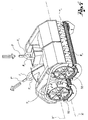
figure 6 shows a cover casing and roller of the opener infigure 1 . - With reference to the appended drawings,
reference numeral 1 globally denotes an assembly for processing fibres in tufts, constituting a section of a fibre processing line, and in particular a section of a carding preparation line. - The
assembly 1 comprises afeed pipe 2 for the transport of the fibre F to be processed, for example coming from a picker. - The
pipe 2, positioned at a predefined height from the ground plane T, extends along a substantially rectilinear feed axis A preferably parallel to the ground plane T. - The
assembly 1 further comprises afeed device 4 suitable for separating the dusty air from the fibre and, preferably for feeding the fibre in tufts downstream. In particular, thefeed device 4 is suitable for deviating the fibre in a feed direction downstream V, for example vertical and perpendicular to the ground plane T (and therefore preferably, perpendicular to the feed axis A). - Preferably, the
assembly 1 comprises aseparator device 6, positioned downstream of thefeed device 4, suitable for separating the fibre flow F coming out of thefeed device 4 into a plurality of separate fibre flows, for example into two fibre flows (F1, F2). - For example, the
separator device 6 comprises aseparation pipe 8 which the fibre traverses, for example of a shape converging in the direction of advancement of the fibre, and aseparator element 10 suitable for separating the fibre F into flows F1, F2. - According to one embodiment the
separator element 10 is a wall fitted with aseparator edge 12 struck by the fibre flow F, housed in theseparation pipe 8. - Preferably, in addition, the
separator element 10 comprises aseparation wall 14 which extends downstream of theseparator edge 12 to keep the fibre flows separate. - Preferably, in addition, the
separator device 6 comprises blower means 20, for example comprising a fan, suitable for blowing a flow of air in the direction of theseparator element 10, to facilitate the separation of the fibre flows F1, F2. - In addition, the
assembly 1 comprises anopener device 30 positioned downstream of thefeed device 4, or of theseparator device 6,fed with the fibre flows, preferably with the two separated fibre flows F1, F2. - The
opener device 30 has afirst compartment 31, for example single, and afirst opener roller 32, housed in said first compartment; thefirst opener roller 32 is motorised and rotatable around a first transversal rotation axis X', that is orthogonal to the feed axis A and the vertical axis V. - Along said rotation axis X', the
first roller 32 extends between a first end 32' and asecond end 32". - The
separator device 6 is suitable for transversally separating the fibre flow F into flows F1, F2. - In addition, preferably, the
separation wall 14 extends as far as to lap the outer surface of thefirst opener roller 32, dividing said roller into portions placed side by side along the rotation axis X' of the first opener roller, joined in rotation, separated, for example imaginarily, by an imaginary first separation line I'. - In particular, in the embodiment shown , the
first opener roller 32 is divided into afirst portion 32a and asecond portion 32b alongside each other along the rotation axis X'. - The
first roller 32 is provided with opening means distributed on its outer surface, suitable for entangling the tufts to open them when pulled. - In particular, the
first portion 32a is fitted with a plurality ofpegs 34a, projecting from the outer surface of thefirst portion 32a of theroller 32, in a rectilinear, broken or ramified direction to have multiple tips. - Preferably, the
pegs 34a are positioned along an imaginary helical line traced on the outer surface of the roller, from the first separation line I' identified by theseparation wall 14 towards the first transversal end 32', according to a first winding angle. - In addition, the
second portion 32b is fitted with a plurality ofpegs 34b, projecting from the outer surface of thesecond portion 32b of theroller 32, in a rectilinear, broken or ramified direction to have multiple tips. - Preferably, the
pegs 34b are positioned along an imaginary helical line traced on the outer surface of the roller, from the first separation line I' identified by theseparation wall 14 towards the second end 32', according to a second winding angle. - Preferably, the two winding angles are equal and opposite.
- In other words, the helical lines are symmetrical in relation to the first separation line I'.
- Preferably, in addition, the
opener device 30 comprises at least one partition 40 (or a plurality of transversally separate partitions placed side by side) for eachportion first roller 32. - The
partition 40 is fixed in relation to the rotation of thefirst roller 32 and encompasses at least partially the outer surface, preferably lapping it without interference. - For each
portion partitions 40 formcentrifugal conduits 42 around the roller, from the centre towards theends 32', 32", preferably having a helical direction, along the outer surface of the roller, at least partially encompassing it. - Preferably, said conduits are positioned on the upper half of the first roller.
- During processing the fibre in tufts is therefore forced to move in the conduits, transversally from the centre towards the
ends 32', 32" of the roller, dragged by the negative pressure air flow and by the pegs, which move in said conduits. - The
opener device 30 also envisages asecond compartment 51, beside thefirst compartment 31 along the feed axis A, and asecond opener roller 52, housed in said second compartment; thesecond opener roller 52 is motorised and rotatable around a second transversal rotation axis X", that is orthogonal to the feed axis A and the vertical axis V, parallel to the first rotation axis X'. - According to one embodiment the
first roller 32 and thesecond roller 52 can be driven in rotation at different rotation speeds. - Along said second rotation axis X", the
second roller 52 extends between a first end 52' and asecond end 52". - For each
portion first roller 32, respective entrances 62', 622 open along the first rotation axis X' between thefirst compartment 31 and thesecond compartment 51. - In particular, in the embodiment shown, the
conduits 42 of thefirst compartment 31, at theends 31', 32" of thefirst roller 32, come out in thesecond compartment 51. - Preferably, the
opener device 30 comprise asecond separation wall 14" which extends as far as to lap the outer surface of thesecond opener roller 52, dividing said roller into portions placed side by side along the rotation axis X", joined in rotation, separated, for example imaginarily, by an imaginary second separation line I". - In particular, in the embodiment shown, the
second opener roller 52 is divided into afirst portion 52a and asecond portion 52b alongside each other along the rotation axis X". - Similarly to the
first roller 32, thesecond roller 52 is also provided with opener means distributed on the outer surface, and in particular with a plurality ofpegs - Preferably, in addition, the
opener device 30 comprises at least one partition 60 (or a plurality of transversally separate partitions placed side by side) for eachportion roller 52, which formcentripetal conduits 72, that is axially converging from theends 52', 52", towards the centre of the second roller, preferably having a helical direction, along the outer surface of the roller, at least partially encompassing it. - Preferably, said conduits are positioned on the upper half of the second roller.
- During processing the fibre in tufts enters the
second compartment 51 through theentrances 62', 62", divided into two flows F1, F2, and is forced to move in the centripetal conduits, moving axially towards the centre of thesecond roller 52. - The
second compartment 51 further envisages anexit 80', 80" for eachportion respective entrances 62', 62", for example at the second separation line I", in communication with anexit mouth 82. - Preferably, the two fibre flows F1, F2 come out of the opener device separately, and according to a preferred embodiment are merged into a single flow of processed fibre F'.
- According to a preferred embodiment the
opener device 30 comprises, associated with eachroller fixed grid 90, fitted with mobile bars, positioned around therespective opener roller - Innovatively, the assembly according to the present invention makes it possible to achieve high quality of the processed fibre, higher than the level which can be achieved processing a single fibre flow, and at the same time to reduce the space occupied compared to the use of separate machines.
- Clearly a person skilled in the art may make modifications to the assembly described above.
- For example, according to one embodiment variation, the two fibre flows F1, F2 are merged at the exit of the second roller, so as to come out of the opener device in a single flow of processed fibre.
- According to a further embodiment variation, the assembly envisages feeding by means of two or more feed ducts; in such variant, the fibre flows are therefore already separate.
- According to yet a further embodiment variation, the entrance of the separated fibre flows to the first opener roller takes place at the ends and the flows proceed on said roller axially towards the centre thereof, while the entrance of the separated fibre flows to the second opener roller takes place at an intermediate position and the flows proceed on said roller axially towards the ends.
- Such variants are also contained within the sphere of protection as defined by the following claims.
Claims (10)
- Opener for fibre in tufts on a carding preparation line, comprising an opener device (30) comprising:- a first compartment (31) and a first opener roller (32), housed in said first compartment, rotatable around a first rotation axis (X'), wherein the first roller (32) extends along said axis between a first end (32') and a second end (32") and presents a plurality of portions (32a,32b) placed side by side and joined in rotation;- a centrifugal conduit (42) for each portion (32a,32b), which winds continuously around the roller (32) from the centre towards its ends (32',32");- a second compartment (51), beside the first compartment (31), and a second opener roller (52), housed in said second compartment, rotatable around a second rotation axis (X''), beside the first rotation axis (X'), wherein the second roller (52) extends along said axis between a first end (62') and a second end (62") and presents a plurality of portions (52a, 52b) placed side by side and joined in rotation;- a centripetal conduit (72) for each portion (52a,52b), which winds around the roller (52) from the respective ends (52', 52") towards its centre;- wherein each centrifugal conduit (42) comes out in the respective centripetal conduit (72).
- Opener according to claim 1, wherein the portions (32a, 32b) of the first compartment (31) and the portions (52a, 52b) of the second compartment (51) are provided with a set of pegs (34a,34b;54a,54b), the pegs of each set being respectively positioned along axially symmetric imaginary helical lines.
- opener according to claim 1 or 2, wherein the first opener roller (32) is fed by a plurality of transversally separate fibre flows (F1,F2), one on each portion (32a, 32b).
- Opener according to any of the previous claims, wherein the second opener roller (52) is fed by a plurality of fibre flows (F1,F2), through entrances (62',62") positioned at the ends (52', 52") of the second roller (52).
- Opener according to any of the previous claims, comprising at least a first partition (40) for each portion (32a, 32b) of the first roller (32), fixed in relation to it, which forms, together with the outer surface of the roller (32), a centrifugal conduit (42), which winds around the roller (32) from the centre towards its ends (32', 32"), preferably in a helical pattern.
- Opener according to any of the previous claims, comprising at least one second partition (60) for each portion (52a,52b) of the second roller (52), fixed in relation to it, which forms, together with the outer surface of the roller (52), a centripetal conduit (62), which winds around the roller (52) from the ends (52',52") of the roller towards the centre, preferably in a helical pattern.
- Opener according to any of the previous claims, comprising a separator device (6) suitable to separate the individual fibre flow (F) from the plurality of transversally separate fibre flows (F1,F2), upstream of the first roller (32).
- Opener according to any of the previous claims, comprising a fixed grid (90), positioned around the respective opener roller (32, 52), preferably in the area under the roller, suitable for removing husks and dirt from the fibre transported in rotation.
- Opener according to any one of the previous claims, wherein the first opener roller (32) and the second opener roller (52) can be activated in rotation at different rotation speeds.
- Method of processing fibre in tufts on a carding preparation line, comprising the steps of:- separating an individual fibre flow (F) from a plurality of separate fibre flows (F1, F2);- feeding both fibre flows (F1, F2), to a single opener roller (32), in an intermediate position between the ends (32', 32") of the roller (32);- making the fibre flows (F1, F2) advance on the opener roller (32) centrifugally from the centre towards the ends (32',32") to perform processing of said fibres;- separately feeding both fibre flows (F1,F2), to a second opener roller (52), through entrances (62',62");- making the fibre flows (F1,F2) advance on the second opener roller (52) centripetally from the entrances (62',62") towards the centre to perform further processing of said fibres.
Applications Claiming Priority (2)
| Application Number | Priority Date | Filing Date | Title |
|---|---|---|---|
| IT000114A ITBS20110114A1 (en) | 2011-08-05 | 2011-08-05 | OPENING FOR FIBER IN FLAKES OF A CARDING PREPARATION LINE |
| EP12176932.7A EP2554726B1 (en) | 2011-08-05 | 2012-07-18 | Opener for fibre in tufts on a carding preparation line |
Related Parent Applications (3)
| Application Number | Title | Priority Date | Filing Date |
|---|---|---|---|
| EP12176932.7A Division EP2554726B1 (en) | 2011-08-05 | 2012-07-18 | Opener for fibre in tufts on a carding preparation line |
| EP12176932.7A Division-Into EP2554726B1 (en) | 2011-08-05 | 2012-07-18 | Opener for fibre in tufts on a carding preparation line |
| EP12176932.7 Division | 2012-07-18 |
Publications (3)
| Publication Number | Publication Date |
|---|---|
| EP2557208A2 EP2557208A2 (en) | 2013-02-13 |
| EP2557208A3 EP2557208A3 (en) | 2014-09-24 |
| EP2557208B1 true EP2557208B1 (en) | 2016-03-16 |
Family
ID=44800101
Family Applications (2)
| Application Number | Title | Priority Date | Filing Date |
|---|---|---|---|
| EP12176932.7A Active EP2554726B1 (en) | 2011-08-05 | 2012-07-18 | Opener for fibre in tufts on a carding preparation line |
| EP12189700.3A Active EP2557208B1 (en) | 2011-08-05 | 2012-07-18 | Opener for fibre in tufts on a carding preparation line |
Family Applications Before (1)
| Application Number | Title | Priority Date | Filing Date |
|---|---|---|---|
| EP12176932.7A Active EP2554726B1 (en) | 2011-08-05 | 2012-07-18 | Opener for fibre in tufts on a carding preparation line |
Country Status (4)
| Country | Link |
|---|---|
| EP (2) | EP2554726B1 (en) |
| CN (1) | CN102912479B (en) |
| BR (1) | BR102012019398B1 (en) |
| IT (1) | ITBS20110114A1 (en) |
Cited By (1)
| Publication number | Priority date | Publication date | Assignee | Title |
|---|---|---|---|---|
| EP3431641A1 (en) | 2017-07-17 | 2019-01-23 | Maschinenfabrik Rieter AG | Cleaning device |
Families Citing this family (9)
| Publication number | Priority date | Publication date | Assignee | Title |
|---|---|---|---|---|
| CN110055627B (en) * | 2019-03-25 | 2021-07-09 | 丹阳市永泰纺织有限公司 | A novel opener for silver is opened |
| CN110184688A (en) * | 2019-05-31 | 2019-08-30 | 河南七彩虹农业科技股份有限公司 | A kind of anticlogging cotton opener |
| CN110042511A (en) * | 2019-05-31 | 2019-07-23 | 河南七彩虹农业科技股份有限公司 | A kind of cotton opener of adjustable clearance |
| DE202020107466U1 (en) | 2020-12-22 | 2022-03-25 | Trützschler GmbH & Co Kommanditgesellschaft | Device on or in a textile machine and textile machine equipped therewith |
| DE102020134590A1 (en) * | 2020-12-22 | 2022-06-23 | Trützschler GmbH & Co Kommanditgesellschaft | Waste removal on a textile machine with several opening rollers, textile machine and installation equipped therewith |
| DE102020134592A1 (en) | 2020-12-22 | 2022-06-23 | Trützschler GmbH & Co Kommanditgesellschaft | Method for operating a device on or in a textile machine and textile machine operated therewith |
| DE102020134589A1 (en) | 2020-12-22 | 2022-06-23 | Trützschler GmbH & Co Kommanditgesellschaft | spinning preparation machine |
| CN116623323A (en) * | 2023-06-27 | 2023-08-22 | 山东天鹅棉业机械股份有限公司 | Nailer Roller and Cotton Cleaner |
| CN117403353A (en) * | 2023-10-17 | 2024-01-16 | 江苏康溢臣生命科技有限公司 | An opening device for flake production equipment |
Family Cites Families (6)
| Publication number | Priority date | Publication date | Assignee | Title |
|---|---|---|---|---|
| DE8712602U1 (en) * | 1987-09-18 | 1989-01-19 | Hergeth Hollingsworth GmbH i.K., 48249 Dülmen | Device for producing a mixture of at least two fibre streams from fibre material, in particular spun material |
| IT1283424B1 (en) | 1996-07-11 | 1998-04-21 | Marzoli & C Spa | DOUBLE DRUM OPENER AND RELATED PROGRESSIVE ACTION OPENING AND CLEANING PROCEDURE FOR STOCK FIBERS |
| WO2007048262A2 (en) * | 2005-10-28 | 2007-05-03 | Maschinenfabrik Rieter Ag | Opening roller and chute feed for a carding machine |
| BRPI0722127A2 (en) * | 2007-12-31 | 2014-04-08 | Marzoli Spa | AXIAL AND ASSEMBLY OPENER FOR TUF FIBER TREATMENT |
| IT1395044B1 (en) | 2009-06-30 | 2012-09-05 | Marzoli Spa | AXIAL OPENING OPTION |
| ITBS20090120A1 (en) * | 2009-06-30 | 2011-01-01 | Marzoli Spa | FEEDER DEVICE FOR A MACHINE FOR FIBER PROCESSING FOR CARDING PREPARATION |
-
2011
- 2011-08-05 IT IT000114A patent/ITBS20110114A1/en unknown
-
2012
- 2012-07-18 EP EP12176932.7A patent/EP2554726B1/en active Active
- 2012-07-18 EP EP12189700.3A patent/EP2557208B1/en active Active
- 2012-08-02 BR BR102012019398-1A patent/BR102012019398B1/en active IP Right Grant
- 2012-08-03 CN CN201210276227.XA patent/CN102912479B/en active Active
Cited By (1)
| Publication number | Priority date | Publication date | Assignee | Title |
|---|---|---|---|---|
| EP3431641A1 (en) | 2017-07-17 | 2019-01-23 | Maschinenfabrik Rieter AG | Cleaning device |
Also Published As
| Publication number | Publication date |
|---|---|
| EP2557208A3 (en) | 2014-09-24 |
| CN102912479B (en) | 2016-08-03 |
| EP2554726B1 (en) | 2014-09-17 |
| EP2554726A2 (en) | 2013-02-06 |
| EP2557208A2 (en) | 2013-02-13 |
| BR102012019398B1 (en) | 2020-12-29 |
| EP2554726A3 (en) | 2013-03-27 |
| ITBS20110114A1 (en) | 2013-02-06 |
| BR102012019398A2 (en) | 2013-11-12 |
| CN102912479A (en) | 2013-02-06 |
Similar Documents
| Publication | Publication Date | Title |
|---|---|---|
| EP2557208B1 (en) | Opener for fibre in tufts on a carding preparation line | |
| JP2009013563A5 (en) | ||
| CN101333702A (en) | Apparatus and method for the fibre-sorting or fibre-selection of a fibre bundle comprising textile fibres | |
| EP2295620A1 (en) | Feeding device of a fibre preparation line for carding | |
| CN101979729B (en) | Seed cotton foreign fiber cleaner | |
| CN102691174A (en) | Production equipment for glass fiber and polypropylene nonwovens | |
| JPS6123286B2 (en) | ||
| US20120149272A1 (en) | Non-woven laying machine and a method for laying a non-woven fabric | |
| EP2225411A1 (en) | Axial opener for the treatment of fiber tufts | |
| EP2449156B1 (en) | Axial opener | |
| CN202576852U (en) | Production equipment for glass fiber and polypropylene fiber non-woven fabric | |
| KR100555188B1 (en) | Fiber bundle collecting device of a spinning machine | |
| CN109208179A (en) | Method and apparatus for pneumatically forming nonwovens | |
| US3443372A (en) | Production of yarn and apparatus for use therein | |
| CN118480886A (en) | High-efficiency production method of polyphenylene sulfide staple yarn | |
| US6058567A (en) | Apparatus and methods for purifying and sorting textile fibers by length using focused energy fields | |
| CN105316811A (en) | Method for producing an air spun yarn | |
| CN101619511A (en) | Feeding device | |
| CN101173387B (en) | Apparatus for the sorting or selection of a fibre sliver comprising textile fibres, especially for combing | |
| WO2017075675A1 (en) | Method and apparatus for production of staple fiber yarn in a single process | |
| US20140173854A1 (en) | Method and apparatus for separating sewing threads and carbon fibers | |
| CN102517695B (en) | Yarn catcher | |
| CN205603752U (en) | Drafting arrangement and spinning machine | |
| CN117468132B (en) | A device for continuously recovering fibers from yarn | |
| EP2499284B1 (en) | Fibers feeding device for feeding tuft to a working machine, like a carding machine |
Legal Events
| Date | Code | Title | Description |
|---|---|---|---|
| PUAI | Public reference made under article 153(3) epc to a published international application that has entered the european phase |
Free format text: ORIGINAL CODE: 0009012 |
|
| AC | Divisional application: reference to earlier application |
Ref document number: 2554726 Country of ref document: EP Kind code of ref document: P |
|
| AK | Designated contracting states |
Kind code of ref document: A2 Designated state(s): AL AT BE BG CH CY CZ DE DK EE ES FI FR GB GR HR HU IE IS IT LI LT LU LV MC MK MT NL NO PL PT RO RS SE SI SK SM TR |
|
| AX | Request for extension of the european patent |
Extension state: BA ME |
|
| PUAL | Search report despatched |
Free format text: ORIGINAL CODE: 0009013 |
|
| AK | Designated contracting states |
Kind code of ref document: A3 Designated state(s): AL AT BE BG CH CY CZ DE DK EE ES FI FR GB GR HR HU IE IS IT LI LT LU LV MC MK MT NL NO PL PT RO RS SE SI SK SM TR |
|
| AX | Request for extension of the european patent |
Extension state: BA ME |
|
| RIC1 | Information provided on ipc code assigned before grant |
Ipc: D01G 9/04 20060101ALI20140818BHEP Ipc: D01G 9/06 20060101AFI20140818BHEP |
|
| 17P | Request for examination filed |
Effective date: 20150317 |
|
| RBV | Designated contracting states (corrected) |
Designated state(s): AL AT BE BG CH CY CZ DE DK EE ES FI FR GB GR HR HU IE IS IT LI LT LU LV MC MK MT NL NO PL PT RO RS SE SI SK SM TR |
|
| GRAP | Despatch of communication of intention to grant a patent |
Free format text: ORIGINAL CODE: EPIDOSNIGR1 |
|
| INTG | Intention to grant announced |
Effective date: 20150827 |
|
| GRAS | Grant fee paid |
Free format text: ORIGINAL CODE: EPIDOSNIGR3 |
|
| RAP1 | Party data changed (applicant data changed or rights of an application transferred) |
Owner name: MARZOLI MACHINES TEXTILE S.R.L. |
|
| GRAA | (expected) grant |
Free format text: ORIGINAL CODE: 0009210 |
|
| AC | Divisional application: reference to earlier application |
Ref document number: 2554726 Country of ref document: EP Kind code of ref document: P |
|
| AK | Designated contracting states |
Kind code of ref document: B1 Designated state(s): AL AT BE BG CH CY CZ DE DK EE ES FI FR GB GR HR HU IE IS IT LI LT LU LV MC MK MT NL NO PL PT RO RS SE SI SK SM TR |
|
| REG | Reference to a national code |
Ref country code: GB Ref legal event code: FG4D |
|
| REG | Reference to a national code |
Ref country code: CH Ref legal event code: EP |
|
| REG | Reference to a national code |
Ref country code: IE Ref legal event code: FG4D |
|
| REG | Reference to a national code |
Ref country code: AT Ref legal event code: REF Ref document number: 781344 Country of ref document: AT Kind code of ref document: T Effective date: 20160415 Ref country code: CH Ref legal event code: NV Representative=s name: JACOBACCI AND PARTNERS SA, CH |
|
| REG | Reference to a national code |
Ref country code: DE Ref legal event code: R096 Ref document number: 602012015609 Country of ref document: DE |
|
| REG | Reference to a national code |
Ref country code: NL Ref legal event code: MP Effective date: 20160316 |
|
| REG | Reference to a national code |
Ref country code: LT Ref legal event code: MG4D |
|
| PG25 | Lapsed in a contracting state [announced via postgrant information from national office to epo] |
Ref country code: HR Free format text: LAPSE BECAUSE OF FAILURE TO SUBMIT A TRANSLATION OF THE DESCRIPTION OR TO PAY THE FEE WITHIN THE PRESCRIBED TIME-LIMIT Effective date: 20160316 Ref country code: NO Free format text: LAPSE BECAUSE OF FAILURE TO SUBMIT A TRANSLATION OF THE DESCRIPTION OR TO PAY THE FEE WITHIN THE PRESCRIBED TIME-LIMIT Effective date: 20160616 Ref country code: GR Free format text: LAPSE BECAUSE OF FAILURE TO SUBMIT A TRANSLATION OF THE DESCRIPTION OR TO PAY THE FEE WITHIN THE PRESCRIBED TIME-LIMIT Effective date: 20160617 Ref country code: FI Free format text: LAPSE BECAUSE OF FAILURE TO SUBMIT A TRANSLATION OF THE DESCRIPTION OR TO PAY THE FEE WITHIN THE PRESCRIBED TIME-LIMIT Effective date: 20160316 |
|
| REG | Reference to a national code |
Ref country code: AT Ref legal event code: MK05 Ref document number: 781344 Country of ref document: AT Kind code of ref document: T Effective date: 20160316 |
|
| PG25 | Lapsed in a contracting state [announced via postgrant information from national office to epo] |
Ref country code: LT Free format text: LAPSE BECAUSE OF FAILURE TO SUBMIT A TRANSLATION OF THE DESCRIPTION OR TO PAY THE FEE WITHIN THE PRESCRIBED TIME-LIMIT Effective date: 20160316 Ref country code: LV Free format text: LAPSE BECAUSE OF FAILURE TO SUBMIT A TRANSLATION OF THE DESCRIPTION OR TO PAY THE FEE WITHIN THE PRESCRIBED TIME-LIMIT Effective date: 20160316 Ref country code: NL Free format text: LAPSE BECAUSE OF FAILURE TO SUBMIT A TRANSLATION OF THE DESCRIPTION OR TO PAY THE FEE WITHIN THE PRESCRIBED TIME-LIMIT Effective date: 20160316 Ref country code: RS Free format text: LAPSE BECAUSE OF FAILURE TO SUBMIT A TRANSLATION OF THE DESCRIPTION OR TO PAY THE FEE WITHIN THE PRESCRIBED TIME-LIMIT Effective date: 20160316 Ref country code: SE Free format text: LAPSE BECAUSE OF FAILURE TO SUBMIT A TRANSLATION OF THE DESCRIPTION OR TO PAY THE FEE WITHIN THE PRESCRIBED TIME-LIMIT Effective date: 20160316 |
|
| PG25 | Lapsed in a contracting state [announced via postgrant information from national office to epo] |
Ref country code: PL Free format text: LAPSE BECAUSE OF FAILURE TO SUBMIT A TRANSLATION OF THE DESCRIPTION OR TO PAY THE FEE WITHIN THE PRESCRIBED TIME-LIMIT Effective date: 20160316 Ref country code: IS Free format text: LAPSE BECAUSE OF FAILURE TO SUBMIT A TRANSLATION OF THE DESCRIPTION OR TO PAY THE FEE WITHIN THE PRESCRIBED TIME-LIMIT Effective date: 20160716 Ref country code: EE Free format text: LAPSE BECAUSE OF FAILURE TO SUBMIT A TRANSLATION OF THE DESCRIPTION OR TO PAY THE FEE WITHIN THE PRESCRIBED TIME-LIMIT Effective date: 20160316 |
|
| PG25 | Lapsed in a contracting state [announced via postgrant information from national office to epo] |
Ref country code: RO Free format text: LAPSE BECAUSE OF FAILURE TO SUBMIT A TRANSLATION OF THE DESCRIPTION OR TO PAY THE FEE WITHIN THE PRESCRIBED TIME-LIMIT Effective date: 20160316 Ref country code: ES Free format text: LAPSE BECAUSE OF FAILURE TO SUBMIT A TRANSLATION OF THE DESCRIPTION OR TO PAY THE FEE WITHIN THE PRESCRIBED TIME-LIMIT Effective date: 20160316 Ref country code: PT Free format text: LAPSE BECAUSE OF FAILURE TO SUBMIT A TRANSLATION OF THE DESCRIPTION OR TO PAY THE FEE WITHIN THE PRESCRIBED TIME-LIMIT Effective date: 20160718 Ref country code: AT Free format text: LAPSE BECAUSE OF FAILURE TO SUBMIT A TRANSLATION OF THE DESCRIPTION OR TO PAY THE FEE WITHIN THE PRESCRIBED TIME-LIMIT Effective date: 20160316 Ref country code: SM Free format text: LAPSE BECAUSE OF FAILURE TO SUBMIT A TRANSLATION OF THE DESCRIPTION OR TO PAY THE FEE WITHIN THE PRESCRIBED TIME-LIMIT Effective date: 20160316 Ref country code: SK Free format text: LAPSE BECAUSE OF FAILURE TO SUBMIT A TRANSLATION OF THE DESCRIPTION OR TO PAY THE FEE WITHIN THE PRESCRIBED TIME-LIMIT Effective date: 20160316 Ref country code: CZ Free format text: LAPSE BECAUSE OF FAILURE TO SUBMIT A TRANSLATION OF THE DESCRIPTION OR TO PAY THE FEE WITHIN THE PRESCRIBED TIME-LIMIT Effective date: 20160316 |
|
| REG | Reference to a national code |
Ref country code: DE Ref legal event code: R097 Ref document number: 602012015609 Country of ref document: DE |
|
| PG25 | Lapsed in a contracting state [announced via postgrant information from national office to epo] |
Ref country code: IT Free format text: LAPSE BECAUSE OF FAILURE TO SUBMIT A TRANSLATION OF THE DESCRIPTION OR TO PAY THE FEE WITHIN THE PRESCRIBED TIME-LIMIT Effective date: 20160316 Ref country code: BE Free format text: LAPSE BECAUSE OF FAILURE TO SUBMIT A TRANSLATION OF THE DESCRIPTION OR TO PAY THE FEE WITHIN THE PRESCRIBED TIME-LIMIT Effective date: 20160316 |
|
| PLBE | No opposition filed within time limit |
Free format text: ORIGINAL CODE: 0009261 |
|
| STAA | Information on the status of an ep patent application or granted ep patent |
Free format text: STATUS: NO OPPOSITION FILED WITHIN TIME LIMIT |
|
| PG25 | Lapsed in a contracting state [announced via postgrant information from national office to epo] |
Ref country code: DK Free format text: LAPSE BECAUSE OF FAILURE TO SUBMIT A TRANSLATION OF THE DESCRIPTION OR TO PAY THE FEE WITHIN THE PRESCRIBED TIME-LIMIT Effective date: 20160316 |
|
| 26N | No opposition filed |
Effective date: 20161219 |
|
| PG25 | Lapsed in a contracting state [announced via postgrant information from national office to epo] |
Ref country code: BG Free format text: LAPSE BECAUSE OF FAILURE TO SUBMIT A TRANSLATION OF THE DESCRIPTION OR TO PAY THE FEE WITHIN THE PRESCRIBED TIME-LIMIT Effective date: 20160616 |
|
| GBPC | Gb: european patent ceased through non-payment of renewal fee |
Effective date: 20160718 |
|
| PG25 | Lapsed in a contracting state [announced via postgrant information from national office to epo] |
Ref country code: MC Free format text: LAPSE BECAUSE OF FAILURE TO SUBMIT A TRANSLATION OF THE DESCRIPTION OR TO PAY THE FEE WITHIN THE PRESCRIBED TIME-LIMIT Effective date: 20160316 |
|
| PG25 | Lapsed in a contracting state [announced via postgrant information from national office to epo] |
Ref country code: FR Free format text: LAPSE BECAUSE OF NON-PAYMENT OF DUE FEES Effective date: 20160801 |
|
| REG | Reference to a national code |
Ref country code: FR Ref legal event code: ST Effective date: 20170331 |
|
| REG | Reference to a national code |
Ref country code: IE Ref legal event code: MM4A |
|
| PG25 | Lapsed in a contracting state [announced via postgrant information from national office to epo] |
Ref country code: SI Free format text: LAPSE BECAUSE OF FAILURE TO SUBMIT A TRANSLATION OF THE DESCRIPTION OR TO PAY THE FEE WITHIN THE PRESCRIBED TIME-LIMIT Effective date: 20160316 Ref country code: GB Free format text: LAPSE BECAUSE OF NON-PAYMENT OF DUE FEES Effective date: 20160718 |
|
| PG25 | Lapsed in a contracting state [announced via postgrant information from national office to epo] |
Ref country code: IE Free format text: LAPSE BECAUSE OF NON-PAYMENT OF DUE FEES Effective date: 20160718 |
|
| PG25 | Lapsed in a contracting state [announced via postgrant information from national office to epo] |
Ref country code: LU Free format text: LAPSE BECAUSE OF NON-PAYMENT OF DUE FEES Effective date: 20160718 |
|
| PG25 | Lapsed in a contracting state [announced via postgrant information from national office to epo] |
Ref country code: HU Free format text: LAPSE BECAUSE OF FAILURE TO SUBMIT A TRANSLATION OF THE DESCRIPTION OR TO PAY THE FEE WITHIN THE PRESCRIBED TIME-LIMIT; INVALID AB INITIO Effective date: 20120718 Ref country code: CY Free format text: LAPSE BECAUSE OF FAILURE TO SUBMIT A TRANSLATION OF THE DESCRIPTION OR TO PAY THE FEE WITHIN THE PRESCRIBED TIME-LIMIT Effective date: 20160316 |
|
| PG25 | Lapsed in a contracting state [announced via postgrant information from national office to epo] |
Ref country code: TR Free format text: LAPSE BECAUSE OF FAILURE TO SUBMIT A TRANSLATION OF THE DESCRIPTION OR TO PAY THE FEE WITHIN THE PRESCRIBED TIME-LIMIT Effective date: 20160316 Ref country code: MK Free format text: LAPSE BECAUSE OF FAILURE TO SUBMIT A TRANSLATION OF THE DESCRIPTION OR TO PAY THE FEE WITHIN THE PRESCRIBED TIME-LIMIT Effective date: 20160316 Ref country code: MT Free format text: LAPSE BECAUSE OF NON-PAYMENT OF DUE FEES Effective date: 20160731 |
|
| PG25 | Lapsed in a contracting state [announced via postgrant information from national office to epo] |
Ref country code: AL Free format text: LAPSE BECAUSE OF FAILURE TO SUBMIT A TRANSLATION OF THE DESCRIPTION OR TO PAY THE FEE WITHIN THE PRESCRIBED TIME-LIMIT Effective date: 20160316 |
|
| P01 | Opt-out of the competence of the unified patent court (upc) registered |
Effective date: 20230523 |
|
| PGFP | Annual fee paid to national office [announced via postgrant information from national office to epo] |
Ref country code: DE Payment date: 20250725 Year of fee payment: 14 |
|
| PGFP | Annual fee paid to national office [announced via postgrant information from national office to epo] |
Ref country code: CH Payment date: 20250801 Year of fee payment: 14 |