EP2556939A1 - Flap device with a sealing element overmoulded onto the flap, method and semi-finished product for the production of same - Google Patents
Flap device with a sealing element overmoulded onto the flap, method and semi-finished product for the production of same Download PDFInfo
- Publication number
- EP2556939A1 EP2556939A1 EP11177437A EP11177437A EP2556939A1 EP 2556939 A1 EP2556939 A1 EP 2556939A1 EP 11177437 A EP11177437 A EP 11177437A EP 11177437 A EP11177437 A EP 11177437A EP 2556939 A1 EP2556939 A1 EP 2556939A1
- Authority
- EP
- European Patent Office
- Prior art keywords
- flap
- housing
- relative
- geometry
- flow channel
- Prior art date
- Legal status (The legal status is an assumption and is not a legal conclusion. Google has not performed a legal analysis and makes no representation as to the accuracy of the status listed.)
- Withdrawn
Links
Images

Classifications
-
- B—PERFORMING OPERATIONS; TRANSPORTING
- B29—WORKING OF PLASTICS; WORKING OF SUBSTANCES IN A PLASTIC STATE IN GENERAL
- B29C—SHAPING OR JOINING OF PLASTICS; SHAPING OF MATERIAL IN A PLASTIC STATE, NOT OTHERWISE PROVIDED FOR; AFTER-TREATMENT OF THE SHAPED PRODUCTS, e.g. REPAIRING
- B29C45/00—Injection moulding, i.e. forcing the required volume of moulding material through a nozzle into a closed mould; Apparatus therefor
- B29C45/0053—Injection moulding, i.e. forcing the required volume of moulding material through a nozzle into a closed mould; Apparatus therefor combined with a final operation, e.g. shaping
- B29C45/0055—Shaping
-
- B—PERFORMING OPERATIONS; TRANSPORTING
- B29—WORKING OF PLASTICS; WORKING OF SUBSTANCES IN A PLASTIC STATE IN GENERAL
- B29C—SHAPING OR JOINING OF PLASTICS; SHAPING OF MATERIAL IN A PLASTIC STATE, NOT OTHERWISE PROVIDED FOR; AFTER-TREATMENT OF THE SHAPED PRODUCTS, e.g. REPAIRING
- B29C45/00—Injection moulding, i.e. forcing the required volume of moulding material through a nozzle into a closed mould; Apparatus therefor
- B29C45/0017—Injection moulding, i.e. forcing the required volume of moulding material through a nozzle into a closed mould; Apparatus therefor moulding interconnected elements which are movable with respect to one another, e.g. chains or hinges
-
- B—PERFORMING OPERATIONS; TRANSPORTING
- B29—WORKING OF PLASTICS; WORKING OF SUBSTANCES IN A PLASTIC STATE IN GENERAL
- B29C—SHAPING OR JOINING OF PLASTICS; SHAPING OF MATERIAL IN A PLASTIC STATE, NOT OTHERWISE PROVIDED FOR; AFTER-TREATMENT OF THE SHAPED PRODUCTS, e.g. REPAIRING
- B29C45/00—Injection moulding, i.e. forcing the required volume of moulding material through a nozzle into a closed mould; Apparatus therefor
- B29C45/0081—Injection moulding, i.e. forcing the required volume of moulding material through a nozzle into a closed mould; Apparatus therefor of objects with parts connected by a thin section, e.g. hinge, tear line
-
- B—PERFORMING OPERATIONS; TRANSPORTING
- B29—WORKING OF PLASTICS; WORKING OF SUBSTANCES IN A PLASTIC STATE IN GENERAL
- B29C—SHAPING OR JOINING OF PLASTICS; SHAPING OF MATERIAL IN A PLASTIC STATE, NOT OTHERWISE PROVIDED FOR; AFTER-TREATMENT OF THE SHAPED PRODUCTS, e.g. REPAIRING
- B29C45/00—Injection moulding, i.e. forcing the required volume of moulding material through a nozzle into a closed mould; Apparatus therefor
- B29C45/14—Injection moulding, i.e. forcing the required volume of moulding material through a nozzle into a closed mould; Apparatus therefor incorporating preformed parts or layers, e.g. injection moulding around inserts or for coating articles
- B29C45/14754—Injection moulding, i.e. forcing the required volume of moulding material through a nozzle into a closed mould; Apparatus therefor incorporating preformed parts or layers, e.g. injection moulding around inserts or for coating articles being in movable or releasable engagement with the coating, e.g. bearing assemblies
-
- B—PERFORMING OPERATIONS; TRANSPORTING
- B29—WORKING OF PLASTICS; WORKING OF SUBSTANCES IN A PLASTIC STATE IN GENERAL
- B29L—INDEXING SCHEME ASSOCIATED WITH SUBCLASS B29C, RELATING TO PARTICULAR ARTICLES
- B29L2031/00—Other particular articles
- B29L2031/748—Machines or parts thereof not otherwise provided for
- B29L2031/7506—Valves
Definitions
- the present invention relates to a method for casting, in particular injection-molding production of a flap device, in particular throttle device, preferably for use in motor vehicles, wherein the flap device comprises a housing which surrounds a flow channel section, and further comprises a flap so movably received on the housing relative to this in that the effective flow cross-section of the flow channel section can be changed by relative displacement of the flap relative to the housing.
- the present invention further relates to a semi-finished product for producing the above-mentioned flap device and the flap device itself.
- the above-mentioned flap device which may have one or more flaps and typically one flap channel per flap, is preferably suitable for use in motor vehicles to provide gas flows there all types, such as a fresh gas supply to the internal combustion engine, flow rate by relative displacement of the at least one flap relative to the housing to change. It is also known, components of such a flap device, such as the flap on the one hand and the housing on the other hand, inexpensive injection molding manufacture.
- annular gap can form between an outer flap edge and a housing section surrounding this outer flap edge in the blocking position of the flap described above. Through this annular gap can continue to flow gas through the flow channel section, although actually a complete shut-off of the flow channel section is desired.
- this object is achieved by a method of the type mentioned, in which the housing and the valve already recorded flap are formed in a mold in a common casting step of a flowable casting molding shaping, namely with integral formation of a compared with the wall thicknesses of the housing and the flap thin G confusematerialphaseutens together with the flap and the housing, wherein the G confusematerialphaseutchen between an outer flap portion and the flap portion is provided in a blocking position of the flap relative to the housing housing portion, in which blocking position the flow cross-section of the flow channel portion in the rule is minimal.
- a semi-finished product is formed by the common casting step in a common mold, in which preferably at least the outer flap edge, but also any other suitable portion of the flap, with the housing section surrounding it in the blocking position of the flap by a comparison with the thickness dimension of the flap thin G cummaterialphaseutchen or a thin G manmaterialgrad is connected.
- the housing and flap are thus preferably produced in the casting step such that the flap is in the blocking position with respect to the housing, that is to say in a position in which the effective flow cross section of the flow channel section is generally minimal.
- This G tellmaterialnosutchen is thin compared to the material thickness of immediately adjacent to it flap portion, in particular flap edge, so that the G collectmaterialnosutchen can be cut with a tool, such as a blade, the flap with the same Tool can not be penetrated or only with disproportionately high power.
- the G hasslematerialkorchen may have about 1% to 40%, preferably 5% to 20%, more preferably 5% to 15%, the wall thickness or average wall thickness of the flap to ensure the above-described property.
- This G hasslestoffputchen integrally connecting the flap and the housing can be essentially the only difference between the demolded after the common casting step semi-finished and the finished, because functional, flap device.
- the method described here preferably comprises the step of severing the G stealmaterialphaseutchens.
- This cutting can, as already explained above, by a tool, in particular cutting tool occur.
- sufficiently thin G cummaterialphaseutchen also be thought to tear the G stealmaterialphaseutchen by forced relative movement of the flap and housing.
- the flap is provided on the finished flap device about a flap axis rotatable relative to the housing on this, if the method is a method step an insertion of a flap shaft component in the mold comprises.
- the flap shaft component can be, for example, a metal component or a component made of another material, which is more dimensionally stable than the cured casting material.
- the flap shaft member is not completely surrounded by casting material contributing to the formation of the flap, while in the case of overmolding the flap shaft component is completely surrounded by casting material contributing to the formation of the flap.
- a bearing means can be provided directly in the mold, which separates the material of the flap of the material of the housing after the casting process, that the flap is indeed received in the housing and supported on this, but in the area this holder casting material of the flap and casting material of the housing are separated by the bearing bush, so that it can come despite the geometric partial penetration of the housing through the flap to a relative movement of flap and housing.
- both the at least one bearing bush and the flap shaft component is inserted into the mold before the casting process, wherein it is advantageous if the method comprises the step of threading the flap shaft component in a bearing bush, preferably in all of the flap of the flap shaft component associated bearing bushes. Then namely the flap shaft component can enforce the bushing and provide not only between the bearing points of the flap on the housing, but especially in the bearing points of the flap on the housing for increased stability of the flap and thus the entire flap device.
- a semifinished product of a flap device in particular throttle device, preferably for use in motor vehicles
- the finished flap device comprises a housing which surrounds a flow channel section
- the finished flap device comprises a housing on the housing relative to this movably received flap, that is adjustable by a relative displacement of the flap relative to the housing, the effective flow cross-section of the flow channel section, in particular manufactured according to the method described above, wherein at least one Klappenabshnitt, in particular an outer flap edge , and a housing portion surrounding the flap in an operative state of the flap device, is connected via a thin material to be skinned compared with the wall thicknesses of the housing and the flap nd are thus integrally formed.
- Such a semi-finished product can be marketed as an independently tradable good on the market, for example from automotive suppliers, which deliver the semi-finished product with intact G stealmaterialphaseutchen to a motor vehicle manufacturer and this the date of commissioning of the semifinished product, ie the production of the flap device from the semifinished product by separation the G fauxmaterialphaseutchens, left.
- the flap on the finished flap device about a damper axis relative to the housing is rotatably provided on this, - may alternatively be thought of a translationally movable flap - it is advantageous if the flap a flap body and at least one with this for common movement having connected flap shaft portion.
- the flap body is then preferably that portion of the flap, with which the above-described change of the flow cross-section is effected by changing the relative arrangement and which is designed for this purpose.
- the flap shaft portion which is preferably integrally formed with the flap body for reasons of dimensional stability and dimensional stability and to avoid unwanted assembly work, is then adapted to receive the flap with the flap body rotatably mounted on the housing.
- the adjacent to the G confusematerialkorutchen flap edge is part of the valve body. In that case, it can then be ensured that the casting material pellet can in fact seal the undesired leakage gap described above.
- a particularly stable bearing of the flap relative rotation relative to the housing can be obtained in that the flap two with respect to the flap axis substantially collinear flap shaft sections wherein the flap body is provided axially between the flap shaft sections. Due to the arrangement of the valve body axially between the valve shaft sections also resulting from operational possibly occurring loads flap bend can be avoided or at least significantly reduced, which could otherwise affect the relative twistability of the flap relative to the housing.
- the flap device or the semifinished product made for the production thereof can have a plurality of flaps, for example if a plurality of identical flow channels lead to each cylinder of a multi-cylinder internal combustion engine and if the gas flow rate in each of the flow channels is to be variable.
- the flaps which are connected to one another at the finished flap relative to the housing relative to the housing, individually, d. H. separately from each other, produced and coupled together only after their production. Therefore, the individual of a plurality of flaps on the semifinished product can still be uncoupled, but can be coupled to one another by form fit geometries or can already be coupled to one another for joint movement.
- the housing may also consist of several housing parts, such as a housing part per flap.
- a housing part per flap it is also conceivable to combine several or even all of the flow channel sections substantially in a common housing part and to supplement this merely by further mounting parts in order to enable a relatively movable attachment of the flaps to the housing part.
- a structurally simple and the following assembly work considerably simplifying solution may be such that one of two connected to a valve body flap shaft portion, preferably at a free axial end thereof, has a coupling geometry and that the respective other flap shaft portion has a coupling counter-geometry, wherein the coupling geometry and the coupling counter-geometry can be positively coupled to a common rotational movement about the valve axis.
- each flap preferably has at one end a coupling geometry and at the other a coupling counter-geometry, so that only one type of flap needs to be manufactured and this flap can be axially lined up as often as required by coupling geometry and coupling counter-geometry so as to provide the desired number of flaps of the respective flap assembly reach.
- a safe and reliable torque transmission from a flap to each their axially adjacent which may be a prerequisite for joint movement, can be obtained in a simple manner that a geometry of coupling geometry and coupling counter-geometry a recess and the other geometry a torque transmitting in the recess insertable projection, preferably a complementary to at least a portion of the recess circumference projection has.
- the projection for torque transmission, the projection, as well as the recess, have a cross-sectional shape when viewing a valve axis orthogonal cross-section, which is bounded by a polygon.
- the projection can be formed prismatic be protrusion and recess for ease of installation can have insertion bevels. This means that the projection tapers with increasing axial distance from the valve body, while the recess tapers with increasing approach to the valve body.
- the preferred complementary configuration of recess and projection should not mean that in the coupled state of recess and projection no voids in the coupling structure more, because usually the recess must always be performed axially a little longer than the projection. Rather, it should be stated that the majority of the recess is taken after the coupling of material of the projection.
- a flap device in particular throttle device, preferably for use in motor vehicles, which comprises a housing which surrounds a flow channel portion, and further comprises a housing on the housing so relative to this movably received flap that a relative displacement of the flap relative to the housing of the effective flow cross section of the flow channel section is variable, in which flap device, a flap portion, preferably an outer flap edge, the at least one flap and / or a flap surrounding portion of the housing as a gap seal at maximum reduced by the flap flow cross-section between the flap portion, in particular flap edge of the flap, and the housing remaining gap has a, preferably completely, circumferential ridge of the same casting material, from which the flap portion, in particular flap edge of the flap, preferably the entire flap, and the housing portion are made.
- the flap device As described above, having a plurality of separately manufactured flaps, it is advantageous if the flap device comprises an actuating member, with which by an actuating device, such as an actuator, an actuating torque for relative rotation of flaps and housing in the Damper device can be introduced so that it can operate at a single actuation site, the entire flap device.
- an actuating device such as an actuator
- the actuation component can already be connected to the at least one flap of the flap device or can still be connected to it. Then it is to simplify the assembly work, but also to the usability of a substantially "universal" flap not only for coupling to another flap, but also for coupling to the operating member advantageous if the actuating member has a geometry of coupling geometry and coupling counter-geometry.
- the coupling ability of a plurality of individually produced flaps by the above-mentioned form-fit geometries should not exclude that these are additionally connected by material connection, such as by the low-distortion laser welding, or by gluing or otherwise operationally inextricably linked to an operation of the flap device with the most accurate change to ensure the flowing through the flow channel section gas flow.
- the above-described flap axis may be arranged such that it passes through the flap body substantially, that is, as in known butterfly flaps. It can also be thought that the flap axis is provided at a distance from the valve body, in which case the valve body is advantageously curved, so that the valve body in a passage position, in which the flow cross-section of the flow channel section is maximum, can rest against the wall of the housing or can cling to them at a short distance.
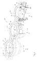
- a first embodiment of a flap device according to the invention is generally designated 10.
- the flap device 10 comprises three channel systems 12, 14 and 16, which are arranged side by side.
- the flap device 10 may have an over-housing 18, which is preferably designed as an integral component and in which further components of the flap device 10 may be accommodated.
- the flap device 10 comprises a housing 20 assigned to the channel system 12, a housing 22 assigned to the channel system 14, and a housing 24 assigned to the channel system 16.
- the flap device 10 has three flow channel sections 26, 28 and 30, in each channel system preferably one, so can be provided three housings 20, 22 and 24, which, as in the in Fig. 1 As shown, for example, the outer housing 18 in the illustrated example.
- the flap device 10 may include a seal assembly 31 around the flap assembly 10 in the direction of the flow channel sections 26, 28 and 30 to seal against a connector, not shown.
- the seal assembly 31 may serve to seal a gap that may exist between a housing 20, 22 or 24 and the housing 18.
- the flap device 10 may also have only one housing 20, two housings 20 and 22, or four or five or six or more housings with or without correspondingly configured housing or housing sections.
- the housing 20 with the flap 32 accommodated therein is described below, it being expressly pointed out that the flaps 34 and 36 are housed in the housings 22 and 22, respectively 24 may be identical, so that this description given for the housing 20 and its interior also applies to the housings 22 and 24.
- the above-mentioned sealing arrangement 31 is preferably a one-piece sealing element with housing seal portions 38, 40 and 42, which may be connected by webs 44 to form an integral component.
- seal assembly 31 preferably integrally connected, have end sealing loops 46 which can serve to seal end-side stub shaft recesses 48 on the housing 18 for receiving end-side stub shafts of the flaps 32, 34 and 36 to a connection piece.
- the seal assembly 31 is formed from a particularly suitable for sealing soft elastic material, for example by injection molding, in any case by a soft elastic material than the outer housing 18, which should show no or only the smallest possible deformation in the intended load case straight.
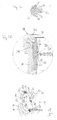
- the housing 20 and the flap 32 provided therein for relative rotation relative to the housing 20 about a valve axis K have been produced in a common molding tool in a common casting step from an identical casting material by casting, preferably by injection molding.
- a flap shaft component 50 which is formed of wear-resistant material than the flap 32 and the housing 20, threaded into bearing bushes 52 and inserted together with them in corresponding cavities and receptacles in the mold.
- the flap 32 which preferably has a flap body 32a and flap shaft sections 32b, is preferably mounted in the housing 20 with two bearing bushes 52 spaced apart in the axial direction with respect to the flap axis K. Axially between the bushings 52, the flap body 32a is preferably arranged so that operationally occurring forces, such as a gas flow along the flow channel section 26, no significant deflection of the flap 32 in the region of the channel axis K is to be feared, which the reliability of the flap device 10 considerably elevated.
- the flap shaft sections 32b which are preferably integrally formed on the flap body 32a, fill a region located radially inside the bushing 52 and contact the bearing bush 52 on a radially inner surface which is in support of the Drehlagerung the flap 32 is preferably cylindrical.
- the inner surface of the bushing 52 may additionally have undercut geometries, such as circumferential projections about the channel axis K and the like, to improve the support of the bearing bush 52 at the flap shaft portion 32 b.
- the housing 20 is at the receiving bushes 52 receiving points preferably radially outwardly encapsulated around the bushings 52, so that the housing 20 is materially separated by the bushes 52 of the flap 32, in particular of the flap shaft portions 32b, so that at the bearing a Relative mobility between the flap 32 and housing 20 is possible.
- Fig. 2 is the storage situation in the partial section well on the channel system 16 recognizable.
- the housing 24, as well as the other housing 20 and / or 22 of the flap device 10, may have a bearing extension 24a, which may rest on a radially outer surface 52a of the bearing bush 52 after removal of the flap device 10.
- the radially outer surface 52a of the bushing 52 may have an undercut geometry to improve the retention of the bushing 52 on the housing.
- the individual housings 20, 22 and 24 are inserted into corresponding staging spaces of the housing 18.
- the seal assembly 31 seals an annular gap between the housings 20, 22 and 24 and the housing 18.
- An anchoring profile 31 b may be formed on the sealing arrangement 31 at the end face opposite its sealing surface 31 a in order to ensure anchoring of the seal 31 to the housings 22, 22 or 24 and / or on the housing 18.
- the coupling shaft component 50 is preferably designed as a prism, for example as a cuboid, in order to facilitate the introduction or / and transmission of a torque acting around the valve axis K.
- the in Fig. 1 identifiable end portions 50a and 50b as positive locking geometries for coupling for example, in the Fig. 1 to 3c Serving components not shown serve, with which a the flaps 32, 34 and 36 actuated actuator for adjusting the flaps 32, 34 and 36 can act on this.
- the flap 32 in particular the flap body 32a of the flap device 10 illustrated in the presently discussed example, can be mirror-symmetrical to a plane of symmetry containing the flap axis K and in particular can extend along a plane.
- annular gap 54 between the flap body 32a and the associated housing 20 to recognize, which exists even if the flap 32 in its in Fig. 3a shown blocking position is located.
- the annular gap 54 extends more exactly along the circumference of the flap body 32a between the flap shaft portions 32b, respectively.
- the G hasslematerialkorutchen 60 is generated in the common casting step, in which both the flap 32 and the housing 20 is formed.
- Fig. 3b thus shows a semifinished state of the flap device 10.
- FIG. 3b IIIc which contains the annular gap 54, is in FIG Fig. 3c shown enlarged.
- the material 60 has a substantially lower material thickness, for example a material thickness of 1 to 20% of the material thickness or middle material thickness of the flap body 32a.
- the G tellmaterialphaseutchen 60 Prior to start-up of the valve device 10, the G tellmaterialphaseutchen 60 is severed with a suitable tool, such as a blade. This can be done on the valve body 32a, then the G stealmaterialphaseutchen 60 remains as a ridge on the housing 20, or can be done on the housing 20, then the G collectmaterialphaseutchen 60 remains as a ridge on the valve body 32a. The latter is preferred due to the thus occurring flow conditions in the associated flow channel section.
- the G mandiotchen 60 After transection, the G mandiol 60 forms as a ridge or
- the G hasslematerialphasechen 60 is produced during common casting, in particular injection molding of flap 32 and housing 20 without significant costs by manufacturing costs and assembly costs and provides below a very effective annular gap seal ready.
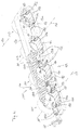
- a second embodiment of the present invention is shown.
- the same components and component portions are provided with the same reference numerals as in the first embodiment of Fig. 1 to 3c , but increased by the number 100.
- the channel device 110 shown here has four substantially parallel flow channel sections 126, 128, 130 and 133, which are formed in a common housing 120.
- the housing 120 may be subdivided in such a way that one or more subgroups of flow channel sections are formed in a housing part. It can also be thought to form a separate housing for each flow channel section.
- the housing 120 may be designed in several parts to facilitate the assembly of the embodiment of a flap device 110 shown here.
- the flaps 132, 134, 136 and 137 may be formed with flap bodies 132a, 134a, 136a and 137a curved according to the shape of the associated flow channel portion, which are then preferably spaced from the flap axis K, around which the entire flap assembly 139 relative to Housing 120 can be rotated. In the in Fig. 4 shown passage position are the valve body 132a, 134a, 136a, and 137a then preferably closely attaches to housing 120 to form a thin gap 141.
- valve bodies can then be in the in Fig. 4 shown passage position in which the respective flow channel sections in the housing 120 substantially have a maximum flow cross-section, create a conforming to the respective wall sections of the housing 120.
- the flap arrangement 139 preferably no flap component protrudes into the flow channel section assigned to it.
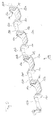
- the flap 137 comprises the already mentioned flap body 137a, from which project to both, with respect to the flap axis K, axial sides flap shaft portions 137b.
- the flap shaft portions 137b are integrally formed with the flap body 137a via land portions 137c.
- Both longitudinal ends of the flap shaft sections 137b which are remote from the flap body 137a can have form fit geometries, which can serve for the torque-transmitting connection with the respectively adjacent flap, here for example flap 136, or / and with an actuating component 162.
- both positive locking geometries can be formed as projections 164.
- the flaps 137 and 134 may be formed substantially identically, and the flaps 136 and 132 may be formed substantially identically, with the difference between adjacent flaps 137 and 136 (see FIGS Fig. 6 ) may consist in that the flap 136 instead of projections 164 coupling recesses 166 has.
- the flap 136 has recesses 166 at both longitudinal ends of the flap shaft sections 136b, remote from the flap body 136a, into which the projections 164 of adjacent flaps can be inserted to connect the flaps to transmit torque.
- each flap has a projection 164 at one longitudinal end of a flap shaft section and a corresponding recess 166 at the respective other longitudinal end. If then, based on the position to the valve body, always the same flap shaft sections have a projection and the other have a recess, it is sufficient to produce a kind of flaps. Essentially identical flaps can thus be put together to form a flap arrangement 139.
- the torque-transmitting components may be non-detachably connected by gluing, welding, or any other suitable method when used as intended.
- a laser welding method is recommended here, which minimizes the thermal distortion occurring and thus ensures the highest possible dimensional stability, combined with a smooth relative rotatability of the flap arrangement 139 relative to the housing 120.
- the coupling projections 164 are preferably constructed prismatic, so that they can transmit torque when combined with the corresponding coupling recesses 166 on the sides of their lateral surfaces.
- the coupling projections 164 are designed as a cuboid.
- flap projections 164 and flap recesses 166 are essentially complementary in the mounted state, that is to say they are complementary to one another, although this is not intended to mean that the coupling recess 166 is in one with a coupling projection 166 United state is completely filled by the coupling projection 164.
- the coupling recess 166 is formed axially longer than the coupling projection 164 already for manufacturing reasons.
- the coupling projection 164 and coupling recess 166 have at least one axial section in which almost the entire circumference of a coupling projection 164 rests on the circumference of the coupling recess 166. In this way, the flaps can be made individually and mounted with little effort to a flap assembly 139 of any length.
- the flap assembly 139 which in the Fig. 4 and 5 four flaps and an operating member 162 may, in alternative embodiments, comprise only one flap 137 and one operating member 162, or may, as in FIG Fig. 6 shown, only two flaps 137 and 136 and an actuating member 162 or may have only three, five, six or more flaps, each with or without operating member 162nd
- the actuating component also has a corresponding form-fit geometry, in this case a coupling recess 166.
- each flap shaft portion is surrounded by a housing extension member 121 and 123, respectively.
- the housing supplemental components 121 and 123 may be substantially identical and differ only in terms of their direction of curvature.
- the housing supplemental components 121 and 123 may be mirror-inverted with respect to a game mirror symmetry plane orthogonal to the channel axis K.
- the flaps required to form a flap arrangement 139 can be combined with one another via the form-fit geometries described above, and preferably fixed in a non-detachable manner.
- an actuating member 162 which can be connected to the flap assembly 139 to transmit torque end.
- the thus formed flap assembly 139 in the housing base member 125 which in Fig. 4 is shown, being used then the respective housing supplement components 121 and 123 complement the housing base member 125 to a housing with complete flow channel sections.
- a bearing bushing 152 can be provided between the housing extension components 121 or 123 and the flap shaft sections 137b, 136b, 134b, 132b passing through them.
- the flaps for example the flap 137
- the flaps may have been cast in a common casting step with the housing supplemental components 121 and 123 in a common mold, for example by injection molding.
- a set of bearing bushes 152 which after demolding the housing extension members 121 and 123 geometrically separated from the flap shaft portions 137b, etc., placed at corresponding locations in the mold and cast around casting material, in particular encapsulated.
- the supplemental components abut an outer surface 152a of the bushing 152, while the flap shaft portions 137b engage an inner surface 152b (see FIG Fig. 6 ) of the bushings 152 abut.
- a flap with the associated housing storage can be produced in a single casting step with high accuracy and substantially constant low bearing clearance without much effort.
- the casting material skin 160 cast in the casting process between the housing extension components 121 and 123 and the associated flap body is only connected to the respective flap body.
Abstract
Description
Die vorliegende Erfindung betrifft ein Verfahren zur gießtechnischen, insbesondere spritzgießtechnischen Herstellung einer Klappenvorrichtung, insbesondere Drosselvorrichtung, bevorzugt zum Einsatz in Kraftfahrzeugen, wobei die Klappenvorrichtung ein Gehäuse umfasst, welches einen Strömungskanalabschnitt umgibt, und weiter eine am Gehäuse derart relativ zu diesem beweglich aufgenommene Klappe umfasst, dass durch eine Relativverstellung der Klappe relativ zum Gehäuse der wirksame Strömungsquerschnitt des Strömungskanalabschnitts veränderbar ist.The present invention relates to a method for casting, in particular injection-molding production of a flap device, in particular throttle device, preferably for use in motor vehicles, wherein the flap device comprises a housing which surrounds a flow channel section, and further comprises a flap so movably received on the housing relative to this in that the effective flow cross-section of the flow channel section can be changed by relative displacement of the flap relative to the housing.
Die vorliegende Erfindung betrifft weiter ein Halbzeug zur Herstellung der oben genannten Klappenvorrichtung sowie die Klappenvorrichtung selbst. Die oben genannte Klappenvorrichtung, die eine oder mehrere Klappen und in der Regel pro Klappe einen Strömungskanalabschnitt aufweisen kann, ist bevorzugt zur Verwendung in Kraftfahrzeugen geeignet, um dort Gasströmungen aller Arten, wie etwa eine Frischgaszufuhr zu der Brennkraftmaschine, mengenstrommäßig durch Relativverstellung der wenigstens einen Klappe relativ zum Gehäuse zu verändern. Es ist überdies bekannt, Komponenten einer derartigen Klappenvorrichtung, wie beispielsweise die Klappe einerseits und das Gehäuse andererseits, kostengünstig spritzgießtechnisch herzustellen.The present invention further relates to a semi-finished product for producing the above-mentioned flap device and the flap device itself. The above-mentioned flap device, which may have one or more flaps and typically one flap channel per flap, is preferably suitable for use in motor vehicles to provide gas flows there all types, such as a fresh gas supply to the internal combustion engine, flow rate by relative displacement of the at least one flap relative to the housing to change. It is also known, components of such a flap device, such as the flap on the one hand and the housing on the other hand, inexpensive injection molding manufacture.
Allerdings kann gerade bei spritzgegossenen Komponenten der Klappenvorrichtung ein Dichtigkeitsproblem auftreten.However, especially with injection-molded components of the flap device, a leakage problem may occur.
Aufgrund von Schwindungsvorgängen oder/und Expansionsvorgängen des Gießmaterials nach der Erstarrung in der Gießform, insbesondere nach der Entformung, kann es zu Leckageproblemen im Spaltbereich zwischen Klappe und Gehäuse kommen. Diese Spaltleckage ist insbesondere dann von Bedeutung, wenn die Klappe den Strömungskanalabschnitt des ihm zugeordneten Gehäuses in einer Sperrstellung im Wesentlichen vollständig verschließen soll.Due to shrinkage processes and / or expansion processes of the casting material after solidification in the casting mold, in particular after demolding, there may be leakage problems in the gap area between the flap and the housing. This gap leakage is particularly of Significance if the flap is to completely close the flow channel section of the associated housing substantially in a blocking position.
Dann kann es aufgrund von fertigungsverfahrensbedingten Ungenauigkeiten zur Ausbildung eines unerwünschten Ringspalts zwischen einem äußeren Klappenrand und einem diesen äußeren Klappenrand in der oben beschriebenen Sperrstellung der Klappe umgebenden Gehäuseabschnitt kommen. Durch diesen Ringspalt kann weiter Gas durch den Strömungskanalabschnitt strömen, obwohl eigentlich eine vollständige Absperrung des Strömungskanalabschnitts gewünscht ist.Then, due to production-related inaccuracies, an undesirable annular gap can form between an outer flap edge and a housing section surrounding this outer flap edge in the blocking position of the flap described above. Through this annular gap can continue to flow gas through the flow channel section, although actually a complete shut-off of the flow channel section is desired.
Zur Abdichtung dieses unerwünschten Ringspalts wird daher im Stand der Technik häufig eine gesondert hergestellte Dichtung in einem Montageschritt an die Klappe anmontiert, was jedoch aufwendig und teuer ist.For sealing this unwanted annular gap, therefore, a separately produced seal is often mounted in an assembly step on the flap in the prior art, but this is complicated and expensive.
Es ist daher Aufgabe der vorliegenden Erfindung, eine technische Lehre anzugeben, mit welcher die eingangs genannte Klappenvorrichtung weiterhin kostengünstig und in großen Stückzahlen herstellbar ist und welche eine Verminderung oder gar Beseitigung des oben beschriebenen Leckageproblems ermöglicht.It is therefore an object of the present invention to provide a technical teaching, with which the above-mentioned flap device is still inexpensive and can be produced in large quantities and which allows a reduction or even elimination of the leakage problem described above.
Gemäß einem ersten Aspekt der vorliegenden Erfindung wird diese Aufgabe gelöst durch ein Verfahren der eingangs genannten Art, bei welchem das Gehäuse und die daran bereits aufgenommene Klappe in einem Formwerkzeug in einem gemeinsamen Gießschritt aus einer fließfähigen Gießmasse formgebend gebildet werden, und zwar unter einstückiger Ausbildung eines verglichen mit den Wandstärken des Gehäuses und der Klappe dünnen Gießmaterialhäutchens zusammen mit der Klappe und dem Gehäuse, wobei das Gießmaterialhäutchen zwischen einem äußeren Klappenabschnitt und einem den Klappenabschnitt in einer Sperrstellung der Klappe relativ zum Gehäuse umgebenden Gehäuseabschnitt vorgesehen wird, in welcher Sperrstellung der Strömungsquerschnitt des Strömungskanalabschnitts in der Regel minimal ist.According to a first aspect of the present invention, this object is achieved by a method of the type mentioned, in which the housing and the valve already recorded flap are formed in a mold in a common casting step of a flowable casting molding shaping, namely with integral formation of a compared with the wall thicknesses of the housing and the flap thin Gießmaterialhäutens together with the flap and the housing, wherein the Gießmaterialhäutchen between an outer flap portion and the flap portion is provided in a blocking position of the flap relative to the housing housing portion, in which blocking position the flow cross-section of the flow channel portion in the rule is minimal.
Wenngleich im Rahmen der vorliegenden Anmeldung stets bevorzugt an ein spritzgießtechnisches Verfahren gedacht ist, sollen andere Gießverfahren nicht ausgeschlossen sein.Although in the context of the present application is always preferred to an injection molding process, other casting methods should not be excluded.
Durch das Ausbilden des Gehäuses und der daran bereits aufgenommenen Klappe in einem einzigen gemeinsamen Gießschritt und in einem gemeinsamen Formwerkzeug mit gemeinsamen Gießmaterial wird zum einen sichergestellt, dass die Materialkenngrößen, wie etwa Schwindung, thermischer Ausdehnungskoeffizient und dergleichen, welche auf die Maßhaltigkeit der Komponenten der Klappenvorrichtung eine Auswirkung haben, für Klappe und für Gehäuse im Wesentlichen identisch sind, so dass einmal erreichte Genauigkeiten und Abmessungen auch im Betrieb unter welchselnden Temperaturen im Wesentlichen beibehalten werden können.By forming the housing and the flap already received in a single common casting step and in a common mold with a common casting material is on the one hand ensures that the material characteristics, such as shrinkage, thermal expansion coefficient and the like, which on the dimensional stability of the components of the flap device have an effect, are substantially identical for the flap and housing, so once achieved accuracies and dimensions can be maintained even in operation under changing temperatures substantially.
Weiterhin wird durch den gemeinsamen Gießschritt in einem gemeinsamen Formwerkzeug ein Halbzeug gebildet, bei welchem bevorzugt wenigstens der äußere Klappenrand, aber auch ein beliebiger anderer geeigneter Abschnitt der Klappe, mit dem ihn in der Sperrstellung der Klappe umgebenden Gehäuseabschnitt durch ein verglichen mit der Dickenabmessung der Klappe dünnes Gießmaterialhäutchen oder einen dünnen Gießmaterialgrad verbunden ist.Furthermore, a semi-finished product is formed by the common casting step in a common mold, in which preferably at least the outer flap edge, but also any other suitable portion of the flap, with the housing section surrounding it in the blocking position of the flap by a comparison with the thickness dimension of the flap thin Gießmaterialhäutchen or a thin Gießmaterialgrad is connected.
Bevorzugt wird also Gehäuse und Klappe in dem Gießschritt derart hergestellt, dass sich die Klappe bezüglich des Gehäuses in der Sperrstellung befindet, also in einer Stellung, in welcher der wirksame Strömungsquerschnitt des Strömungskanalabschnitts in der Regel minimal ist.The housing and flap are thus preferably produced in the casting step such that the flap is in the blocking position with respect to the housing, that is to say in a position in which the effective flow cross section of the flow channel section is generally minimal.
Dieses Gießmaterialhäutchen ist verglichen mit der Materialdicke des unmittelbar an ihn angrenzenden Klappenabschnitts, insbesondere Klappenrandes, dünn ausgebildet, damit das Gießmaterialhäutchen mit einem Werkzeug, wie etwa einer Klinge, durchtrennt werden kann, die Klappe mit demselben Werkzeug jedoch nicht oder nur mit unverhältnismäßig hoher Kraft durchdrungen werden kann.This Gießmaterialhäutchen is thin compared to the material thickness of immediately adjacent to it flap portion, in particular flap edge, so that the Gießmaterialhäutchen can be cut with a tool, such as a blade, the flap with the same Tool can not be penetrated or only with disproportionately high power.
Dann kann nämlich das beim gemeinsamen Gießschritt von Gehäuse und Klappe gebildete Gießmaterialhäutchen als Spaltdichtung wirken. Damit wird eine Anbringung einer gesonderten Dichtung überflüssig. Vielmehr kann eine ansonsten im Stand der Technik zur Vermeidung der oben beschriebenen Leckageverluste notwendige zusätzliche, also gesondert von Klappe und Gehäuse ausgebildete, Dichtung vermieden werden.Then, namely, the Gießmaterialhäutchen formed during the common casting step of the housing and flap can act as a gap seal. This makes it unnecessary to attach a separate seal. Rather, an otherwise necessary in the prior art to avoid the leakage losses described above additional, so separately formed by flap and housing, seal can be avoided.
Das Gießmaterialhäutchen kann zur Gewährleistung der oben beschriebenen Eigenschaft etwa 1 % bis 40 %, bevorzugt 5 % bis 20 %, besonders bevorzugt 5 % bis 15 %, der Wandstärke oder mittleren Wandstärke der Klappe aufweisen.The Gießmaterialhäutchen may have about 1% to 40%, preferably 5% to 20%, more preferably 5% to 15%, the wall thickness or average wall thickness of the flap to ensure the above-described property.
Dies bedeutet, dass ein derart in einem Gießschritt erzeugtes Halbzeug aus Gehäuse und Klappe zwar die Klappe bereits drehbar im Gehäuse gelagert aufweist, eine Relativdrehung der Klappe relativ zum Gehäuse unmittelbar nach dem Entformen jedoch durch das Gießmaterialhäutchen verhindert ist.This means that a semifinished product of housing and flap thus produced in a casting step has the flap already rotatably mounted in the housing, however, a relative rotation of the flap relative to the housing is prevented immediately after demolding by the Gießmaterialhäutchen.
Dieses die Klappe und das Gehäuse einstückig verbindende Gießmaterialhäutchen kann im Wesentlichen der einzige Unterschied zwischen dem nach dem gemeinsamen Gießschritt entformten Halbzeug und der fertiggestellten, weil funktionstüchtigen, Klappenvorrichtung sein.This Gießstoffhäutchen integrally connecting the flap and the housing can be essentially the only difference between the demolded after the common casting step semi-finished and the finished, because functional, flap device.
Zur Herstellung der Funktionstüchigkeit der Klappenvorrichtung umfasst daher das hier beschriebene Verfahren vorzugsweise den Schritt eines Durchtrennens des Gießmaterialhäutchens. Dieses Durchtrennen kann, wie oben bereits dargelegt wurde, durch ein Werkzeug, insbesondere Schneidwerkzeug, erfolgen. Grundsätzlich kann jedoch bei ausreichend dünnem Gießmaterialhäutchen auch daran gedacht sein, das Gießmaterialhäutchen durch Zwangsrelativbewegung von Klappe und Gehäuse zu zerreißen.To produce the functionality of the flap device, therefore, the method described here preferably comprises the step of severing the Gießmaterialhäutchens. This cutting can, as already explained above, by a tool, in particular cutting tool occur. In principle, however, with sufficiently thin Gießmaterialhäutchen also be thought to tear the Gießmaterialhäutchen by forced relative movement of the flap and housing.
Letzteres, wenngleich es von der vorliegenden Erfindung umfasst sein soll, ist jedoch nicht bevorzugt, da es bei einem derartigen Reißvorgang zu einer unerwünschten Dehnung des Gießmaterials im Gießmaterialhäutchen kommen kann, so dass es im späteren Betrieb der Klappenvorrichtung zu einer unerwünschten Reibung des aus dem gedehnten und gerissenen Gießmaterialhäutchen hervorgehenden Grats am äußeren Klappenabschnitt, insbesondere Klappenrand, oder/und an dem betreffenden Gehäuseabschnitt kommen kann.The latter, although it is intended to be encompassed by the present invention, is not preferred, however, since in such a rupture process undesirable elongation of the casting material in the pellicle may occur, resulting in unwanted friction from the stretched pellicle during subsequent operation of the valve device and cracked Gießmaterialhäutchen forth ridge on the outer flap portion, in particular flap edge, and / or come to the respective housing portion.
Zur Bereitstellung einer möglichst genauen, also form- oder/und maßhaltigen, Relativbewegung zwischen Klappe und Gehäuse kann es dann, wenn die Klappe an der fertigen Klappenvorrichtung um eine Klappenachse relativ zum Gehäuse verdrehbar an diesem vorgesehen ist, vorteilhaft sein, wenn das Verfahren einen Verfahrensschritt eines Einlegens eines Klappenwellenbauteils in das Formwerkzeug umfasst.To provide the most accurate, so dimensional or / and dimensional, relative movement between the flap and the housing, it may be advantageous if the flap is provided on the finished flap device about a flap axis rotatable relative to the housing on this, if the method is a method step an insertion of a flap shaft component in the mold comprises.
Das Klappenwellenbauteil kann beispielsweise ein Metallbauteil oder ein Bauteil aus einem sonstigen Material, welches formstabiler als das ausgehärtete Gießmaterial ist, sein.The flap shaft component can be, for example, a metal component or a component made of another material, which is more dimensionally stable than the cured casting material.
Dann ist es nämlich möglich, die Klappe an das Klappenwellenbauteil anzugießen, insbesondere anzuspritzen, oder das Klappenwellenbauteil mit der Klappe zu umgießen, insbesondere zu umspritzen.In that case it is possible to apply the flap to the flap shaft component, in particular to inject it, or to encase the flap shaft component with the flap, in particular to overmold it.
Im erstgenannten Fall des Angießens ist das Klappenwellenbauteil nicht vollständig von zur Bildung der Klappe beitragendem Gießmaterial umgeben, während im Falle des Umgießens das Klappenwellenbauteil vollständig von zur Bildung der Klappe beitragenden Gießmaterial umgeben ist.In the former case of the casting, the flap shaft member is not completely surrounded by casting material contributing to the formation of the flap, while in the case of overmolding the flap shaft component is completely surrounded by casting material contributing to the formation of the flap.
Das Umgießen ist dabei bevorzugt, da das umgossene Klappenwellenbauteil zum einen durch das Gießmaterial der Klappe weitgehend geschützt ist und überdies an der Außenfläche der mit dem Klappenwellenbauteil verstärkten Klappe keine unerwünschte Materialpaarung auftritt, die bei Relativbewegung von Klappe und Gehäuse zu unerwünschtem Verschleiß führen kann.The Umgießen is preferred because the encapsulated Klappenwellenbauteil is largely protected by the casting material of the flap on the one hand and also on the outer surface of the flap shaft member reinforced flap no unwanted material pairing occurs, the relative movement from flap and housing can lead to unwanted wear.
Weiterhin kann für den oben genannten Fall einer um eine Klappenachse verdrehbaren Klappe relativ zum Gehäuse vorgesehen sein, dass das Verfahren folgende weitere Verfahrensschritte aufweist:
- Einlegen wenigstens einer Lagerbuchse in das Formwerkzeug, vorzugsweise von zwei Lagerbuchsen, besonders bevorzugt derart, dass zwischen zwei derselben Klappe zugeordneten Lagerbuchsen ein Abschnitt einer Klappenkavität des Formwerkzeugs gelegen ist, und
- Angießen, insbesondere Anspritzen, von zur Bildung der Klappe beitragendem Gießmaterial an eine erste, der Klappe zugeordnete Klappenlagerfläche der Lagerbuchse, und
- Angießen, insbesondere Anspritzen, von zur Bildung des Gehäuses beitragendem Gießmaterial an eine von der ersten verschiedene zweite, dem Gehäuse zugeordnete Gehäuselagerfläche der Lagerbuchse.
- Inserting at least one bearing bush in the mold, preferably of two bushings, particularly preferably such that between two of the same flap associated bushings, a portion of a Klappenkavität the mold is located, and
- Casting, in particular injection molding, from casting material contributing to the formation of the flap to a first flap bearing surface of the bearing bush associated with the flap, and
- Casting, in particular injection molding, of casting material contributing to the formation of the housing to a second housing housing surface of the bearing bush, which is different from the first housing and is associated with the housing.
Durch das Einlegen der Lagerbuchse in das Formwerkzeug kann also ein Lagermittel unmittelbar im Formwerkzeug bereitgestellt werden, welches nach erfolgtem Gießvorgang das Material der Klappe vom Material des Gehäuses derart trennt, dass die Klappe zwar im Gehäuse aufgenommen und an diesem gehaltert ist, dass aber im Bereich dieser Halterung Gießmaterial der Klappe und Gießmaterial des Gehäuses durch die Lagerbuchse voneinander getrennt sind, so dass es trotz geometrischer Teildurchdringung des Gehäuses durch die Klappe zu einer Relativbewegung von Klappe und Gehäuse kommen kann.By inserting the bearing bush into the mold so a bearing means can be provided directly in the mold, which separates the material of the flap of the material of the housing after the casting process, that the flap is indeed received in the housing and supported on this, but in the area this holder casting material of the flap and casting material of the housing are separated by the bearing bush, so that it can come despite the geometric partial penetration of the housing through the flap to a relative movement of flap and housing.
Dabei soll nicht ausgeschlossen sein, dass an anderer Stelle, etwa in einem axial außerhalb des Gehäuses liegenden Bereich, Gießmaterial des Gehäuses und Gießmaterial der Klappe miteinander verströmt sind und dieser Strömungsbereich erst vom entformten Halbzeug abgetrennt werden muss, bevor nach Trennung des Gießmaterialhäutchens eine Relativbeweglichkeit von Klappe und Gehäuse hergestellt ist. In diesem Falle würde ein derartiger Zusammenströmungsbereich einen weiteren Unterschied, zusätzlich zum Gießmaterialhäutchen, zwischen dem Halbzeug und der fertigen Klappenvorrichtung darstellen.In this case, it should not be ruled out that casting material of the housing and casting material of the flap are leaked to one another at a different location, for example in an area located axially outside the housing, and this flow area must first be separated from the demoulded semi-finished product before a relative mobility of the material after separation of the casting material Flap and housing is made. In this case, such would Confluent area another difference, in addition to Gießmaterialhäutchen, between the semifinished product and the finished flap device represent.
Bevorzugt wird ein derartiger Zusammenströmungsbereich jedoch vermieden, um die erforderliche Nacharbeit des gegossenen Halbzeugs in ihrem Umfang so gering wie möglich zu halten.Preferably, however, such a confluence region is avoided in order to minimize the required reworking of the cast semifinished product in its circumference.
Vorzugsweise wird sowohl die wenigstens eine Lagerbuchse als auch das Klappenwellenbauteil vor dem Gießvorgang in das Formwerkzeug eingelegt, wobei es dann vorteilhaft ist, wenn das Verfahren den Schritt eines Einfädelns des Klappenwellenbauteils in eine Lagerbuchse, vorzugsweise in alle der Klappe des Klappenwellenbauteils zugeordnete Lagerbuchsen, umfasst. Dann nämlich kann das Klappenwellenbauteil die Lagerbuchse durchsetzen und nicht nur zwischen den Lagerstellen der Klappe am Gehäuse, sondern vor allem in den Lagerstellen der Klappe am Gehäuse für eine erhöhte Stabilität der Klappe und somit der gesamten Klappenvorrichtung sorgen.Preferably, both the at least one bearing bush and the flap shaft component is inserted into the mold before the casting process, wherein it is advantageous if the method comprises the step of threading the flap shaft component in a bearing bush, preferably in all of the flap of the flap shaft component associated bearing bushes. Then namely the flap shaft component can enforce the bushing and provide not only between the bearing points of the flap on the housing, but especially in the bearing points of the flap on the housing for increased stability of the flap and thus the entire flap device.
Wie der obigen Beschreibung unschwer zu entnehmen ist, wird die eingangs erläuterte, der vorliegenden Erfindung zugrunde liegende technische Aufgabe auch gelöst durch ein Halbzeug einer Klappenvorrichtung, insbesondere Drosselvorrichtung, bevorzugt zum Einsatz in Kraftfahrzeugen, wobei die fertiggestellte Klappenvorrichtung ein Gehäuse umfasst, welches einen Strömungskanalabschnitt umgibt, und weiter eine am Gehäuse derart relativ zu diesem beweglich aufgenommene Klappe umfasst, dass durch eine Relativverstellung der Klappe relativ zum Gehäuse der wirksame Strömungsquerschnitt des Strömungskanalabschnitts veränderbar ist, insbesondere hergestellt nach dem oben beschriebenen Verfahren, bei welchem wenigstens ein Klappenabshnitt, insbesondere ein äußerer Klappenrand, und ein in betriebsmäßigem Zustand der Klappenvorrichtung die Klappe umgebender Gehäuseabschnitt über ein verglichen mit den Wandstärken des Gehäuses und der Klappe dünnes Gießmaterialhäutchen verbunden und somit einstückig ausgebildet sind.As the above description is readily apparent, the technical problem underlying the present invention is also solved by a semifinished product of a flap device, in particular throttle device, preferably for use in motor vehicles, wherein the finished flap device comprises a housing which surrounds a flow channel section , And further comprises a housing on the housing relative to this movably received flap, that is adjustable by a relative displacement of the flap relative to the housing, the effective flow cross-section of the flow channel section, in particular manufactured according to the method described above, wherein at least one Klappenabshnitt, in particular an outer flap edge , and a housing portion surrounding the flap in an operative state of the flap device, is connected via a thin material to be skinned compared with the wall thicknesses of the housing and the flap nd are thus integrally formed.
Ein derartiges Halbzeug kann als selbständig handelbares Gut am Markt vertrieben werden, etwa von Kfz-Zulieferbetrieben, welche das Halbzeug mit intaktem Gießmaterialhäutchen an einen Kfz-Hersteller liefern und diesem den Zeitpunkt der Inbetriebnahme des Halbzeugs, also der Herstellung der Klappenvorrichtung aus dem Halbzeug durch Trennung des Gießmaterialhäutchens, überlassen.Such a semi-finished product can be marketed as an independently tradable good on the market, for example from automotive suppliers, which deliver the semi-finished product with intact Gießmaterialhäutchen to a motor vehicle manufacturer and this the date of commissioning of the semifinished product, ie the production of the flap device from the semifinished product by separation the Gießmaterialhäutchens, left.
Dann, wenn die Klappe an der fertigen Klappenvorrichtung um eine Klappenachse relativ zum Gehäuse verdrehbar an diesem vorgesehen ist, - alternativ kann auch an eine translatorisch bewegbare Klappe gedacht sein - ist es vorteilhaft, wenn die Klappe einen Klappenkörper und wenigstens einen mit diesem zur gemeinsamen Bewegung verbundenen Klappenwellenabschnitt aufweist. Der Klappenkörper ist dann bevorzugt jener Abschnitt der Klappe, mit welchem die oben beschriebene Veränderung des Strömungsquerschnitts durch Änderung der Relativanordnung bewirkt wird und welcher hierfür ausgebildet ist.Then, when the flap on the finished flap device about a damper axis relative to the housing is rotatably provided on this, - may alternatively be thought of a translationally movable flap - it is advantageous if the flap a flap body and at least one with this for common movement having connected flap shaft portion. The flap body is then preferably that portion of the flap, with which the above-described change of the flow cross-section is effected by changing the relative arrangement and which is designed for this purpose.
Der Klappenwellenabschnitt, welcher aus Gründen der Maßhaltigkeit und Formstabilität sowie zur Vermeidung unerwünschten Montageaufwands bevorzugt einstückig mit dem Klappenkörper ausgebildet ist, ist dann dazu ausgebildet, die Klappe mit dem Klappenkörper drehbar am Gehäuse aufzunehmen.The flap shaft portion, which is preferably integrally formed with the flap body for reasons of dimensional stability and dimensional stability and to avoid unwanted assembly work, is then adapted to receive the flap with the flap body rotatably mounted on the housing.
Um die Dichtungswirkung des Gießmaterialhäutchens gewährleisten zu können, ist es vorteilhaft, wenn der an das Gießmaterialhäutchen angrenzende Klappenrand Teil des Klappenkörpers ist. Dann kann nämlich gewährleistet werden, dass das Gießmaterialhäutchen tatsächlich den eingangs beschriebenen unerwünschten Leckagespalt abdichten kann.In order to be able to ensure the sealing effect of the Gießmaterialhäutchens, it is advantageous if the adjacent to the Gießmaterialhäutchen flap edge is part of the valve body. In that case, it can then be ensured that the casting material pellet can in fact seal the undesired leakage gap described above.
Eine besonders stabile Lagerung der Klappe zur Relativverdrehung relativ zum Gehäuse kann dadurch erhalten werden, dass die Klappe zwei bezüglich der Klappenachse im Wesentlichen kollineare Klappenwellenabschnitte aufweist, wobei der Klappenkörper axial zwischen den Klappenwellenabschnitten vorgesehen ist. Durch die Anordnung des Klappenkörpers axial zwischen den Klappenwellenabschnitten kann überdies eine aus betriebsbedingt möglicherweise auftretenden Lasten resultierende Klappenbiegung vermieden oder wenigstens erheblich reduziert werden, welche ansonsten die Relativverdrehbarkeit der Klappe relativ zum Gehäuse beeinträchtigen könnte.A particularly stable bearing of the flap relative rotation relative to the housing can be obtained in that the flap two with respect to the flap axis substantially collinear flap shaft sections wherein the flap body is provided axially between the flap shaft sections. Due to the arrangement of the valve body axially between the valve shaft sections also resulting from operational possibly occurring loads flap bend can be avoided or at least significantly reduced, which could otherwise affect the relative twistability of the flap relative to the housing.
In vielen Fällen kann die Klappenvorrichtung oder das zu ihrer Herstellung angefertigte Halbzeug mehrere Klappen aufweisen, etwa wenn mehrere gleichartige Strömungskanäle zu jedem Zylinder einer Mehrzylinder-Brennkraftmaschine führen und der Gasmengenstrom in jedem der Strömungskanäle veränderbar sein soll.In many cases, the flap device or the semifinished product made for the production thereof can have a plurality of flaps, for example if a plurality of identical flow channels lead to each cylinder of a multi-cylinder internal combustion engine and if the gas flow rate in each of the flow channels is to be variable.
Dann ist es zur Erhöhung der Fertigungs- und Montagegenauigkeit und damit zur Genauigkeit der Gasmengenstromsteuerung oder -regelung äußerst vorteilhaft, wenn benachbarte Klappen durch Formschlussgeometrien zur gemeinsamen Bewegung miteinander koppelbar oder gekoppelt sind.Then it is extremely advantageous for increasing the manufacturing and assembly accuracy and thus for the accuracy of the gas flow rate control or regulation when adjacent flaps can be coupled or coupled to each other by form fit geometries for common movement.
Dies bedeutet, dass die Klappen, die an der fertiggestellten Klappenvorrichtung zur gemeinsamen Relativverstellung relativ zum Gehäuse miteinander verbunden sind, einzeln, d. h. gesondert voneinander, hergestellt und erst nach ihrer Herstellung miteinander gekoppelt werden. Deshalb können die einzelnen einer Mehrzahl von Klappen am Halbzeug noch ungekoppelt, aber miteinander durch Formschlussgeometrien koppelbar sein oder können bereits miteinander zur gemeinsamen Bewegung gekoppelt sein.This means that the flaps, which are connected to one another at the finished flap relative to the housing relative to the housing, individually, d. H. separately from each other, produced and coupled together only after their production. Therefore, the individual of a plurality of flaps on the semifinished product can still be uncoupled, but can be coupled to one another by form fit geometries or can already be coupled to one another for joint movement.
Dabei kann das Gehäuse ebenfalls aus mehreren Gehäuseteilen bestehen, etwa aus einem Gehäuseteil pro Klappe. Ebenso ist es jedoch denkbar, mehrere oder sogar alle Strömungskanalabschnitte im Wesentlichen in einem gemeinsamen Gehäuseteil zusammenzufassen und dieses lediglich um weitere Montageteile zu ergänzen, um eine relativbewegliche Anbringung der Klappen an dem Gehäuseteil zu ermöglichen.In this case, the housing may also consist of several housing parts, such as a housing part per flap. However, it is also conceivable to combine several or even all of the flow channel sections substantially in a common housing part and to supplement this merely by further mounting parts in order to enable a relatively movable attachment of the flaps to the housing part.
Eine konstruktiv einfache und die folgende Montagearbeit erheblich vereinfachende Lösung kann dergestalt sein, dass der eine von zwei mit einem Klappenkörper verbundene Klappenwellenabschnitt, vorzugsweise an einem freien axialen Ende desselben, eine Kopplungsgeometrie aufweist und dass der jeweils andere Klappenwellenabschnitt eine Kopplungsgegengeometrie aufweist, wobei die Kopplungsgeometrie und die Kopplungsgegengeometrie formschlüssig zu einer gemeinsamen Drehbewegung um die Klappenachse koppelbar sind.A structurally simple and the following assembly work considerably simplifying solution may be such that one of two connected to a valve body flap shaft portion, preferably at a free axial end thereof, has a coupling geometry and that the respective other flap shaft portion has a coupling counter-geometry, wherein the coupling geometry and the coupling counter-geometry can be positively coupled to a common rotational movement about the valve axis.
Somit weist jede Klappe bevorzugt einenends eine Kopplungsgeometrie und andernends eine Kopplungsgegengeometrie auf, so dass nur eine Art von Klappe hergestellt zu werden braucht und diese Klappe beliebig oft durch Kopplungsgeometrie und Kopplungsgegengeometrie axial aneinander gereiht werden kann, um so zu der gewünschten Klappenanzahl der jeweiligen Klappenanordnung zu gelangen.Thus, each flap preferably has at one end a coupling geometry and at the other a coupling counter-geometry, so that only one type of flap needs to be manufactured and this flap can be axially lined up as often as required by coupling geometry and coupling counter-geometry so as to provide the desired number of flaps of the respective flap assembly reach.
Eine sichere und zuverlässige Drehmomentübertragung von einer Klappe zu der ihr jeweils axial benachbarten, was eine Voraussetzung für eine gemeinsame Bewegung sein kann, kann in einfacher Weise dadurch erhalten werden, dass eine Geometrie aus Kopplungsgeometrie und Kopplungsgegengeometrie eine Ausnehmung und die jeweils andere Geometrie einen drehmomentübertragend in die Ausnehmung einführbaren Vorsprung, vorzugsweise einen zu wenigstens einem Abschnitt des Ausnehmungsumfangs komplementären Vorsprung, aufweist. Durch entsprechende Wahl der axialen Länge von Ausnehmung und Vorsprung kann die an der drehmomentübertragenden Kopplungsstelle auftretende Flächenbelastung von Kopplungsgeometrie und Kopplungsgegengeometrie gering gehalten werden.A safe and reliable torque transmission from a flap to each their axially adjacent, which may be a prerequisite for joint movement, can be obtained in a simple manner that a geometry of coupling geometry and coupling counter-geometry a recess and the other geometry a torque transmitting in the recess insertable projection, preferably a complementary to at least a portion of the recess circumference projection has. By appropriate choice of the axial length of the recess and projection, the surface loading of coupling geometry and coupling counter-geometry occurring at the torque-transmitting coupling point can be kept low.
Beispielsweise kann zur Drehmomentübertragung der Vorsprung, ebenso wie die Ausnehmung, eine Querschnittsgestalt bei Betrachtung eines zur Klappenachse orthogonalen Querschnitts aufweisen, welche durch einen Polygonzug berandet ist. Allgemein kann der Vorsprung prismatisch ausgebildet sein, wobei Vorsprung und Ausnehmung zur erleichterten Montage Einführschrägen aufweisen können. Dies bedeutet, dass sich der Vorsprung mit zunehmender axialer Entfernung vom Klappenkörper verjüngt, während sich die Ausnehmung mit zunehmender Annäherung an den Klappenkörper verjüngt.For example, for torque transmission, the projection, as well as the recess, have a cross-sectional shape when viewing a valve axis orthogonal cross-section, which is bounded by a polygon. In general, the projection can be formed prismatic be protrusion and recess for ease of installation can have insertion bevels. This means that the projection tapers with increasing axial distance from the valve body, while the recess tapers with increasing approach to the valve body.
Die bevorzugte komplementäre Ausgestaltung von Ausnehmung und Vorsprung soll nicht bedeuten, dass im gekoppelten Zustand von Ausnehmung und Vorsprung keine Leerräume in dem Kopplungsgebilde mehr bestehen, denn üblicherweise muss die Ausnehmung stets axial ein wenig länger ausgeführt werden als der Vorsprung. Vielmehr soll damit ausgesagt sein, dass der überwiegende Teil der Ausnehmung nach der Kopplung von Material des Vorsprungs eingenommen ist.The preferred complementary configuration of recess and projection should not mean that in the coupled state of recess and projection no voids in the coupling structure more, because usually the recess must always be performed axially a little longer than the projection. Rather, it should be stated that the majority of the recess is taken after the coupling of material of the projection.
Die oben genannten Vorteile zum Halbzeug treffen mutatis mutandis auch auf die Klappenvorrichtung zu, deren wesentlichster oder sogar einziger Unterschied darin besteht, dass das Gießmaterialhäutchen, welches ursprünglich Klappe und Gehäuse miteinander verbindet, bei der Klappenvorrichtung bereits durchtrennt wurde, so dass aus dem verbleibenden Restmaterial des Gießmaterialhäutchens ein Grat zurückbleibt. Daher wird die eingangs genannte Aufgabe der vorliegenden Erfindung auch gelöst durch eine Klappenvorrichtung, insbesondere Drosselvorrichtung, bevorzugt zum Einsatz in Kraftfahrzeugen, welche ein Gehäuse umfasst, das einen Strömungskanalabschnitt umgibt, und weiter eine am Gehäuse derart relativ zu diesem beweglich aufgenommene Klappe umfasst, dass durch eine Relativverstellung der Klappe relativ zum Gehäuse der wirksame Strömungsquerschnitt des Strömungskanalabschnitts veränderbar ist, bei welcher Klappenvorrichtung ein Klappenabschnitt, vorzugsweise ein äußerer Klappenrand, der wenigstens einen Klappe oder/und ein die Klappe umgebender Abschnitt des Gehäuses als Spaltdichtung des bei maximal durch die Klappe reduzierten Strömungsquerschnitts zwischen dem Klappenabschnitt, insbesondere Klappenrand der Klappe, und dem Gehäuse verbleibenden Spalt einen, vorzugsweise vollständig, umlaufenden Grat aus demselben Gießmaterial aufweist, aus dem der Klappenabschnitt, insbesondere Klappenrand der Klappe, vorzugsweise die gesamte Klappe, und der Gehäuseabschnitt hergestellt sind.The above-mentioned advantages for semifinished products apply mutatis mutandis to the valve device, the most significant or even only difference being that the Gießmaterialhäutchen, which originally connects flap and housing together, was already severed at the flap device, so that from the remaining material of the Gießmaterialhäutchens a ridge remains. Therefore, the above-mentioned object of the present invention is also achieved by a flap device, in particular throttle device, preferably for use in motor vehicles, which comprises a housing which surrounds a flow channel portion, and further comprises a housing on the housing so relative to this movably received flap that a relative displacement of the flap relative to the housing of the effective flow cross section of the flow channel section is variable, in which flap device, a flap portion, preferably an outer flap edge, the at least one flap and / or a flap surrounding portion of the housing as a gap seal at maximum reduced by the flap flow cross-section between the flap portion, in particular flap edge of the flap, and the housing remaining gap has a, preferably completely, circumferential ridge of the same casting material, from which the flap portion, in particular flap edge of the flap, preferably the entire flap, and the housing portion are made.
Das oben zum Halbzeug Gesagte, insbesondere die Weiterbildungen des die eingangs genannte Aufgabe lösenden erfindungsgemäßen Halbzeugs, gilt ebenso für die obige, ebenfalls erfindungsgemäße Klappenvorrichtung als Lösung der obigen Aufgabe, welche also in gleicher Weise wie das obige Halbzeug weitergebildet sein kann. Die obigen Weiterbildungen des Halbzeugs sind daher auch auf die Klappenvorrichtung zu lesen und anwendbar.The above for semi-finished, in particular the developments of the above-mentioned object solving semifinished product according to the invention also applies to the above, likewise inventive flap device as a solution to the above problem, which can therefore be developed in the same manner as the above semifinished product. The above developments of the semifinished product are therefore also to be read and applicable to the flap device.
Wenn die Klappenvorrichtung, wie oben bereits beschrieben, eine Mehrzahl von gesondert voneinander gefertigten Klappen aufweist, ist es vorteilhaft, wenn die Klappenvorrichtung ein Betätigungsbauteil aufweist, mit welchem durch ein Betätigungsgerät, etwa durch einen Aktuator, ein Betätigungsdrehmoment zur Relativverdrehung von Klappen und Gehäuse in die Klappenvorrichtung einleitbar ist, um somit an einer einzigen Betätigungsstelle die gesamte Klappenvorrichtung betätigen zu können.When the flap device, as described above, having a plurality of separately manufactured flaps, it is advantageous if the flap device comprises an actuating member, with which by an actuating device, such as an actuator, an actuating torque for relative rotation of flaps and housing in the Damper device can be introduced so that it can operate at a single actuation site, the entire flap device.
Das Betätigungsbauteil kann bereits mit der wenigstens einen Klappe der Klappenvorrichtung verbunden oder noch mit dieser verbindbar sein. Dann ist es zur Vereinfachung der Montagearbeit, aber auch zur Verwendbarkeit einer im Wesentlichen "universellen" Klappe nicht nur zur Ankopplung an eine andere Klappe, sondern auch zur Ankopplung an das Betätigungsbauteil vorteilhaft, wenn auch das Betätigungsbauteil eine Geometrie aus Kopplungsgeometrie und Kopplungsgegengeometrie aufweist.The actuation component can already be connected to the at least one flap of the flap device or can still be connected to it. Then it is to simplify the assembly work, but also to the usability of a substantially "universal" flap not only for coupling to another flap, but also for coupling to the operating member advantageous if the actuating member has a geometry of coupling geometry and coupling counter-geometry.
Die Koppelbarkeit einer Mehrzahl von einzeln hergestellten Klappen durch die zuvor genannten Formschlussgeometrien soll nicht ausschließen, dass diese zusätzlich durch Stoffschluss, etwa durch das besonders verzugsarme Laserschweißen, oder durch Klebung oder sonstwie betriebsmäßig unlösbar miteinander verbunden sind, um einen Betrieb der Klappenvorrichtung mit möglichst genauer Veränderung des durch den Strömungskanalabschnitt strömenden Gasmengenstroms sicherstellen zu können.The coupling ability of a plurality of individually produced flaps by the above-mentioned form-fit geometries should not exclude that these are additionally connected by material connection, such as by the low-distortion laser welding, or by gluing or otherwise operationally inextricably linked to an operation of the flap device with the most accurate change to ensure the flowing through the flow channel section gas flow.
Die oben bezeichnete Klappenachse kann derart angeordnet sein, dass sie den Klappenkörper im Wesentlichen durchsetzt, also etwa wie bei bekannten Schmetterlingsklappen. Ebenso kann daran gedacht sein, dass die Klappenachse mit Abstand vom Klappenkörper vorgesehen ist, wobei dann der Klappenkörper vorteilhafterweise gekrümmt ausgebildet ist, so dass der Klappenkörper in einer Durchlassstellung, in welcher der Strömungsquerschnitt des Strömungskanalabschnitts maximal ist, an die Wandung des Gehäuses anliegen kann oder sich an diese in geringer Entfernung anschmiegen kann.The above-described flap axis may be arranged such that it passes through the flap body substantially, that is, as in known butterfly flaps. It can also be thought that the flap axis is provided at a distance from the valve body, in which case the valve body is advantageously curved, so that the valve body in a passage position, in which the flow cross-section of the flow channel section is maximum, can rest against the wall of the housing or can cling to them at a short distance.
Im erstgenannten Fall der Schmetterlingsklappe ist diese aus Gründen einer möglichst einfachen Fertigung vorteilhafterweise eben, also erstreckt sich längs einer Ebene.In the former case of the butterfly flap this is advantageously flat for reasons of simplest possible production, that extends along a plane.
Die vorliegende Erfindung wird nachfolgend anhand der beiliegenden Figuren näher erläutert. Es stellt dar:
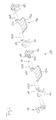
- Fig. 1
- eine perspektivische Explosionsansicht einer ersten erfindungsgemäßen Ausführungsform einer Klappenvorrichtung,
- Fig. 2
- die Klappenvorrichtung von
Fig. 1 im Teilschnitt im montierten Zustand, - Fig. 3a
- eine Querschnittsansicht durch die
Klappenanordnung 12 vonFig. 2 mit einer zur Klappenachse orthogonalen Querschnittsebene, - Fig. 3b
- eine vergrößerte Detailansicht des Bereichs IIIb aus
Fig. 3a und - Fig. 3c
- eine vergrößerte Detailansicht des Ausschnitts IIIc aus
Fig. 3b , - Fig. 4
- eine zweite Ausführungsform einer erfindungsgemäßen Klappen-vorrichtung in perspektivischer Ansicht im Teilschnitt,
- Fig. 5
- eine perspektivische Darstellung der Klappen, Lagerbuchsen und des Betätigungsbauteils der Klappenvorrichtung der zweiten Ausführungsform von
Fig. 4 , und - Fig. 6
- die beiden dem Betätigungsbauteil axial am nächsten liegenden Klappen der Klappenanordnung von
Fig. 5 in der Explosionsansicht.
- Fig. 1
- an exploded perspective view of a first embodiment of a flap device according to the invention,
- Fig. 2
- the flap device of
Fig. 1 in partial section in the assembled state, - Fig. 3a
- a cross-sectional view through the
flap assembly 12 ofFig. 2 with a cross-sectional plane orthogonal to the valve axis, - Fig. 3b
- an enlarged detail view of the area IIIb
Fig. 3a and - Fig. 3c
- an enlarged detail view of the section IIIc
Fig. 3b . - Fig. 4
- A second embodiment of a flap device according to the invention in a perspective view in partial section,
- Fig. 5
- a perspective view of the flaps, bushings and the actuating member of the flap device of the second embodiment of
Fig. 4 , and - Fig. 6
- the two axially closest to the actuating member flaps of the flap assembly of
Fig. 5 in the exploded view.
In
Die Klappenvorrichtung 10 umfasst drei Kanalsysteme 12, 14 und 16, welche nebeneinander angeordnet sind.The
Hierzu kann die Klappenvorrichtung 10 ein Übergehäuse 18 aufweisen, welches vorzugsweise als ein integrales Bauteil ausgebildet ist und in welchem weitere Bauteile der Klappenvorrichtung 10 aufgenommen sein können.For this purpose, the
Weiter umfasst die Klappenvorrichtung 10 im dargestellten Beispiel ein dem Kanalsystem 12 zugeordnetes Gehäuse 20, ein dem Kanalsystem 14 zugeordnetes Gehäuse 22 und ein dem Kanalsystem 16 zugeordnetes Gehäuse 24.Furthermore, in the illustrated example, the
Im dargestellten Beispiel, in welchem die Klappenvorrichtung 10 drei Strömungskanalabschnitte 26, 28 und 30 aufweist, in jedem Kanalsystem vorzugsweise eines, können also drei Gehäuse 20, 22 und 24 vorgesehen sein, welche, wie in dem in
Weiter kann die Klappenvorrichtung 10 eine Dichtungsanordnung 31 aufweisen, um die Klappenanordnung 10 in Richtung der Strömungskanalabschnitte 26, 28 und 30 gegen ein nicht dargestelltes Anschlussstück dichtend anzuschließen. Überdies kann die Dichtungsanordnung 31 dazu dienen, einen möglicherweise zwischen einem Gehäuse 20, 22 oder 24 und dem Übergehäuse 18 bestehenden Spalt abzudichten.Furthermore, the
Es sei ausdrücklich darauf hingewiesen, dass abweichend von der Darstellung der
Da die Gehäuse 20, 22 und 24 in dem in
Die zuvor angesprochene Dichtungsanordnung 31 ist vorzugsweise ein einstückiges Dichtungselement mit Gehäusedichtungsabschnitten 38, 40 und 42, welche durch Stege 44 zu einem integralen Bauteil verbunden sein können.The above-mentioned
Weiterhin kann die Dichtungsanordnung 31, bevorzugt integral angebunden, endseitige Dichtungsschlaufen 46 aufweisen, welche dazu dienen können, endseitige Wellenstumpfausnehmungen 48 an dem Übergehäuse 18 zur Aufnahme endseitiger Wellenstümpfe der Klappen 32, 34 und 36 zu einem Anschlussstück hin abzudichten.Furthermore, the
Vorzugsweise ist die Dichtungsanordnung 31 aus einem für eine Abdichtung besonders gut geeigneten weichelastischen Material gebildet, beispielsweise durch Spritzgießen, jedenfalls durch ein weicherelastisches Material als das Übergehäuse 18, welches gerade keine oder nur eine möglichst geringe Verformung im bestimmungsgemäßen Belastungsfall zeigen soll.Preferably, the
Das Gehäuse 20 und die darin zur Relativverdrehung relativ zum Gehäuse 20 um eine Klappenachse K vorgesehene Klappe 32 sind in einem gemeinsamen Formwerkzeug in einem gemeinsamen Gießschritt aus einem identischen Gießmaterial gießtechnisch, bevorzugt spritzgießtechnisch, hergestellt worden.The
Hierzu wurde bevorzugt vor dem Gießschritt ein Klappenwellenbauteil 50, welches aus verschleißfesterem Material gebildet ist als die Klappe 32 und das Gehäuse 20, in Lagerbuchsen 52 eingefädelt und zusammen mit diesen in entsprechende Kavitäten und Aufnahmen im Formwerkzeug eingelegt.For this purpose, preferably before the casting step, a
Dadurch war es vorteilhafterweise möglich, das Klappenwellenbauteil 50 mit Gießmaterial zur Bildung der Klappe 32 zu umgießen, insbesondere zu umspritzen.As a result, it was advantageously possible to encase the
Die Klappe 32, welche vorzugsweise einen Klappenkörper 32a und Klappenwellenabschnitte 32b aufweist, ist vorzugsweise mit zwei in axialer Richtung bezüglich der Klappenachse K mit Abstand voneinander angeordneten Lagerbuchsen 52 im Gehäuse 20 gelagert. Axial zwischen den Lagerbuchsen 52 ist bevorzugt der Klappenkörper 32a angeordnet, so dass durch betriebsmäßig auftretende Kräfte, etwa durch eine Gasströmung entlang des Strömungskanalabschnitts 26, keine wesentliche Durchbiegung der Klappe 32 im Bereich der Kanalachse K zu befürchten ist, was die Betriebssicherheit der Klappenvorrichtung 10 erheblich erhöht.The
Die vorzugsweise integral an den Klappenkörper 32a angeformten Klappenwellenabschnitte 32b füllen in dem dargestellten Beispiel einen radial innerhalb der Lagerbuchse 52 gelegenen Bereich aus und berühren die Lagerbuchse 52 an einer radial inneren Fläche, welche zur Unterstützung der Drehlagerung der Klappe 32 vorzugsweise zylindrisch ausgebildet ist. Die Innenfläche der Lagerbuchse 52 kann zusätzlich Hinterschneidungsgeometrien, etwa um die Kanalachse K umlaufende Vorsprünge und dergleichen, aufweisen, um den Halt der Lagerbuchse 52 am Klappenwellenabschnitt 32b zu verbessern.In the example shown, the
Dagegen ist das Gehäuse 20 an den die Lagerbuchsen 52 aufnehmenden Stellen vorzugsweise radial außen um die Lagerbuchsen 52 umspritzt, so dass das Gehäuse 20 durch die Lagerbuchsen 52 von der Klappe 32, insbesondere von den Klappenwellenabschnitten 32b materialmäßig getrennt ist, so dass an der Lagerstelle eine Relativbeweglichkeit zwischen Klappe 32 und Gehäuse 20 ermöglicht ist.In contrast, the
In
Hier ist insbesondere zu sehen, dass das Gehäuse 24, ebenso wie die anderen Gehäuse 20 oder/und 22 der Klappenvorrichtung 10, einen Lagerfortsatz 24a aufweisen kann, welcher nach dem Entformen der Klappenvorrichtung 10 an einer radial äußeren Fläche 52a der Lagerbuchse 52 anliegen kann. Auch die radial äußere Fläche 52a der Lagerbuchse 52 kann eine Hinterschneidungsgeometrie aufweisen, um den Halt der Lagerbuchse 52 am Gehäuse zu verbessern.Here it can be seen in particular that the
Durch die Verwendung des identischen Gießmaterials zur Herstellung der Gehäuse einerseits und der Klappen andererseits kann überdies ein im Wesentlichen gleichförmiges und einheitliches Lagerspiel an der Relativverdrehlagerung der Klappen an den Gehäusen erreicht werden.Moreover, by using the identical casting material for producing the housings on the one hand and the flaps on the other hand, a substantially uniform and uniform bearing play can be achieved on the relative rotational mounting of the flaps on the housings.
Wie weiter in
An dem seiner Dichtflläche 31 a gegenüberliegenden Endfläche kann an der Dichtungsanordnung 31 ein Verankerungsprofil 31 b ausgebildet sein, um eine Verankerung der Dichtung 31 an den Gehäusen 22, 22 bzw. 24 oder/und am Übergehäuse 18 zu gewährleisten.An anchoring profile 31 b may be formed on the sealing
Das Kopplungswellenbauteil 50 ist im vorliegenden Fall vorzugsweise als Prisma, beispielsweise als Quader, ausgebildet, um die Einleitung oder/und Übertragung eines um die Klappenachse K wirkenden Drehmoments zu erleichtern. Beispielsweise können die in
In der Querschnittsdarstellung von
Weiter ist in
Der in
Dort ist zu erkennen, wie zwischen einem Außenrand 56 des Klappenkörpers 32a und einer dem Außenrand 56 gegenüberliegenden Innenwandung 58 des Gehäuses 20 ein Gießmaterialhäutchen 60 den Ringspalt 54 überbrückend sowohl mit dem Klappenkörper 32a als auch mit dem Gehäuse 20 verbunden ist.It can be seen there, as between an
Das Gießmaterialhäutchen 60 wird bei dem gemeinsamen Gießschritt, in welchem sowohl die Klappe 32 als auch das Gehäuse 20 gebildet wird, erzeugt.The
Der in
Dort ist zu erkennen, dass das Gießmaterialhäutchen 60 verglichen mit der Materialstärke des Klappenkörpers 32a, insbesondere in dessen äußerem Randbereich 56, eine wesentlich geringere Materialstärke aufweist, etwa eine Materialstärke von 1 bis 20 % der Materialstärke bzw. mittleren Materialstärke des Klappenkörpers 32a.There, it can be seen that compared to the material thickness of the
Vor der Inbetriebnahme der Klappenvorrichtung 10 wird das Gießmaterialhäutchen 60 mit einem geeigneten Werkzeug, etwa einer Klinge, durchtrennt. Dies kann am Klappenkörper 32a geschehen, dann verbleibt das Gießmaterialhäutchen 60 als Grat am Gehäuse 20, oder kann am Gehäuse 20 geschehen, dann verbleibt das Gießmaterialhäutchen 60 als Grat am Klappenkörper 32a. Letzteres ist aufgrund der damit eintretenden Strömungsverhältnisse im zugeordneten Strömungskanalabschnitt bevorzugt.Prior to start-up of the
Grundsätzlich soll jedoch auch nicht ausgeschlossen sein, dass das Gießmaterialhäutchen 60 in einem Bereich zwischen den beiden Bauteilen: Klappenkörper 32a und Gehäuse 20, durchtrennt wird, so dass das Gießmaterialhäutchen 60 als Teilgrat zu einem Teil am Klappenkörper 32a und zum anderen Teil am Gehäuse 20 verbleibt.Basically, however, should not be ruled out that the
Nach der Durchtrennung bildet das Gießmaterialhäutchen 60 als Grat oderAfter transection, the
Teilgrat eine exakt passende Dichtung des Ringspalts 54, so dass Leckageströmungen durch den Ringspalt 54 hindurch in der Sperrstellung der Klappe 32 vermieden oder zumindest stark reduziert werden können.Teilgrat a precisely fitting seal of the
Das Gießmaterialhäutchen 60 wird beim gemeinsamen Gießen, insbesondere Spritzgießen, von Klappe 32 und Gehäuse 20 ohne nennenswerte Kosten durch Fertigungsaufwand und Montageaufwand hergestellt und stellt nachfolgend eine sehr wirksame Ringspaltdichtung bereit.The
In den
Die hier gezeigte Kanalvorrichtung 110 weist vier im Wesentlichen parallele Strömungskanalabschnitte 126, 128, 130 und 133 auf, welche in einem gemeinsamen Gehäuse 120 ausgebildet sind.The channel device 110 shown here has four substantially parallel
Alternativ hierzu kann das Gehäuse 120 auf die Art unterteilt sein, dass ein oder mehrere Untergruppen von Strömungskanalabschnitten in einem Gehäuseteil ausgebildet sind. Dabei kann ebenfalls daran gedacht sein, für jeden Strömungskanalabschnitt ein gesondertes Gehäuse auszubilden.Alternatively, the
Wie weiter unten noch ausgeführt werden wird, kann das Gehäuse 120 zur Erleichterung der Montage des hier gezeigten Ausführungsbeispiels einer Klappenvorrichtung 110 mehrteilig ausgeführt sein.As will be explained below, the
Die Klappen 132, 134, 136 und 137 können mit entsprechend der Gestalt des zugeordneten Strömungskanalabschnitts gekrümmten Klappenkörpern 132a, 134a, 136a und 137a ausgebildet sein, welche dann vorzugsweise mit Abstand von der Klappenachse K angeordnet sind, um welche herum die gesamte Klappenanordnung 139 relativ zum Gehäuse 120 verdrehbar sein kann. In der in
Die Klappenkörper können dann in der in
Die hier diskutierte zweite Ausführungsform einer erfindungsgemäßen Klappenvorrichtung 110 soll nachfolgend anhand der in
Die Klappe 137 umfasst den bereits genannten Klappenkörper 137a, von welchem zu beiden, bezogen auf die Klappenachse K, axialen Seiten Klappenwellenabschnitte 137b abstehen.The
Vorzugsweise sind die Klappenwellenabschnitte 137b über Stegabschnitte 137c integral mit dem Klappenkörper 137a ausgeformt.Preferably, the
Beide vom Klappenkörper 137a fern liegenden Längsenden der Klappenwellenabschnitte 137b können Formschlussgeometrien aufweisen, welche zur drehmomentübertragenden Verbindung mit der jeweils benachbarten Klappe, hier beispielsweise Klappe 136, oder/und mit einem Betätigungsbauteil 162 dienen können.Both longitudinal ends of the
In dem in
Dann können die Klappen 137 und 134 im Wesentlichen identisch ausgebildet sein, und können die Klappen 136 und 132 im Wesentlichen identisch ausgebildet sein, wobei der Unterschied zwischen benachbarten Klappen 137 und 136 (siehe
In dem dargestellten Beispiel weist die Klappe 136 an beiden vom Klappenkörper 136a fern liegenden Längsenden der Klappenwellenabschnitte 136b Ausnehmungen 166 auf, in welche die Vorsprünge 164 benachbarter Klappen eingeführt werden können, um die Klappen drehmomentübertragend miteinander zu verbinden.In the illustrated example, the
Die in den
Nach dem Zusammenstecken benachbarter Klappen oder/und eines Betätigungsbauteils 162 können die zur Drehmomentübertragung gesteckten Komponenten zusätzlich durch Kleben, Schweißen oder ein beliebiges anderes geeignetes Verfahren bei bestimmungsgemäßem Gebrauch unlösbar verbunden werden.Additionally, after mating adjacent flaps or / and an operating
Bevorzugt wird hier ein Laserschweißverfahren empfohlen, welches den auftretenden thermischen Verzug minimiert und damit eine möglichst hohe Maßhaltigkeit, verbunden mit einer leichtgängigen Relativverdrehbarkeit der Klappenanordnung 139 relativ zum Gehäuse 120, gewährleistet.Preferably, a laser welding method is recommended here, which minimizes the thermal distortion occurring and thus ensures the highest possible dimensional stability, combined with a smooth relative rotatability of the
Ebenfalls denkbar, wenngleich aufgrund des erhöhten Montageaufwands nicht bevorzugt, ist es, alle Klappen mit Kopplungsausnehmungen 166 auszubilden und gesondert ausgebildete Verbindungssteine in Form der Kopplungsvorsprünge 164 in die Kopplungsausnehmungen 166 benachbarter Klappen einzuführen. Zwar sind dann auch bei dieser Lösung alle Klappen im Wesentlichen geometrisch identisch, jedoch ist der Montageaufwand durch die einzuführenden Kopplungssteine unerwünscht hoch.It is also conceivable, although not preferred due to the increased assembly effort, to form all the flaps with
Die Kopplungsvorsprünge 164 sind vorzugsweise prismatisch aufgebaut, so dass sie bei Vereinigung mit den entsprechenden Kopplungsausnehmungen 166 an den Seiten ihrer Mantelflächen Drehmoment übertragen können. Im dargestellten Beispiel sind die Kopplungsvorsprünge 164 als Quader gestaltet. Jedoch ist ebenso denkbar, die Kopplungsvorsprünge 164 als Dreiecksprisma, Fünfecksprisma oder als unregelmäßiges Prisma zu gestalten.The
Ebenso reicht es aus, die Ausnehmungen 166 derart auszubilden, dass Abschnitte der Innenmantelfläche einer Ausnehmung 166 an Abschnitte der Mantelfläche der Kopplungsvorsprünge 164 zur Anlage kommen und an dieser Anlage ein Drehmoment um die Klappenachse K zwischen zwei derart gekoppelten Klappen übertragbar ist.It is also sufficient to form the
Bevorzugt ist jedoch zur Erzielung einer möglichst exakten Geometrie der zusammengebauten Klappenanordnung 139, dass sich Klappenvorsprünge 164 und Klappenausnehmungen 166 im montierten Zustand im Wesentlichen ergänzen, also komplementär zueinander ausgebildet sind, wobei dies nicht bedeuten soll, dass die Kopplungsausnehmung 166 in einem mit einem Kopplungsvorsprung 166 vereinigten Zustand vollständig von dem Kopplungsvorsprung 164 ausgefüllt ist. Üblicherweise ist bereits aus fertigungstechnischen Gründen die Kopplungsausnehmung 166 axial länger ausgebildet als der Kopplungsvorsprung 164. Jedoch ist es vorteilhaft, wenn Kopplungsvorsprung 164 und Kopplungsausnehmung 166 wenigstens einen Axialabschnitt aufweisen, in welchem nahezu der gesamte Umfang eines Kopplungsvorsprungs 164 am Umfang der Kopplungsausnehmung 166 anliegt. Auf diese Art und Weise können die Klappen einzeln gefertigt und mit geringem Aufwand zu einer Klappenanordnung 139 mit beliebiger Länge montiert werden.However, in order to achieve the most exact possible geometry of the assembled
Die Klappenanordnung 139, welche in den
Wie ebenso in den Figuren gezeigt ist, weist auch das Betätigungsbauteil eine entsprechende Formschlussgeometrie auf, hier eine Kopplungsausnehmung 166.As also shown in the figures, the actuating component also has a corresponding form-fit geometry, in this case a
Wie in den
Die Gehäuseergänzungsbauteile 121 bzw. 123 können im Wesentlichen identisch sein und sich lediglich in hinsichtlich ihrer Krümmungsrichtung unterscheiden. Beispielsweise können die Gehäuseergänzungsbauteile 121 und 123 bezüglich einer zur Kanalachse K orthogonalen Spielgelsymmetrieebene spiegelbildlich aufgebaut sein.The housing
Dann, wenn jede Klappe die ihr zugeordneten Ergänzungsbauteile 121 und 123 aufweist, können die zur Bildung einer Klappenanordnung 139 benötigten Klappen über die oben beschriebenen Formschlussgeometrien drehmomentübertragend miteinander vereinigt und vorzugsweise unlösbar fixiert werden. Gleiches gilt für ein Betätigungsbauteil 162, welches endseitig an die Klappenanordnung 139 drehmomentübertragend anschließbar sein kann. Dann kann die so gebildete Klappenanordnung 139 in das Gehäusegrundbauteil 125, welches in
Wiederum kann zwischen den Gehäuseergänzungsbauteilen 121 bzw. 123 und den sie durchsetzenden Klappenwellenabschnitten 137b, 136b, 134b, 132b eine Lagerbuchse 152 vorgesehen sein.Again, a bearing
Im vorliegenden Fall können die Klappen, beispielsweise die Klappe 137, in einem gemeinsamen Gießschritt mit den Gehäuseergänzungsbauteilen 121 und 123 in einem gemeinsamen Formwerkzeug gegossen worden sein, beispielsweise durch Spritzgießen. Hierzu wurde bevorzugt vor dem Gießschritt in das Formwerkzeug ein Satz an Lagerbuchsen 152, welche nach dem Entformen die Gehäuseergänzungsbauteile 121 und 123 geometrisch von den Klappenwellenabschnitten 137b usw. trennen, an entsprechende Stellen im Formwerkzeug eingelegt und mit Gießmaterial umgossen, insbesondere umspritzt.In the present case, the flaps, for example the
Somit liegen die Ergänzungsbauteile an einer Außenfläche 152a der Lagerbuchse 152 an, während die Klappenwellenabschnitte 137b an einer innenfläche 152b (siehe
Daher kann eine Klappe mit der zugehörigen Gehäuselagerung in einem einzigen Gießschritt mit hoher Genauigkeit und im Wesentlichen gleichbleibendem geringem Lagerspiel ohne großen Aufwand erzeugt werden.Therefore, a flap with the associated housing storage can be produced in a single casting step with high accuracy and substantially constant low bearing clearance without much effort.
Da in den
Claims (15)
dadurch gekennzeichnet, dass das Gehäuse (20, 22, 24; 120) und die daran bereits aufgenommene Klappe (32, 34, 36; 132, 134, 136, 137) in einem Formwerkzeug in einem gemeinsamen Gießschritt aus einer fließfähigen Gießmasse formgebend gebildet werden, und zwar unter einstückiger Ausbildung eines verglichen mit den Wandstärken des Gehäuses (20, 22, 24; 120) und der Klappe (32, 34, 36; 132, 134, 136, 137) dünnen Gießmaterialhäutchens (60; 160) zusammen mit der Klappe (32, 34, 36; 132, 134, 136, 137) und dem Gehäuse (20, 22, 24; 120), wobei das Gießmaterialhäutchen (60; 160) zwischen einem äußeren Klappenabschnitt, bevorzugt genauer zwischen einem äußeren Klappenrand (56), und einem den Klappenabschnitt, bevorzugt den Klappenrand (56), in einer Sperrstellung der Klappe (32, 34, 36; 132, 134, 136, 137) relativ zum Gehäuse (20, 22, 24; 120) umgebenden Gehäuseabschnitt vorgesehen wird, in welcher Sperrstellung der Strömungsquerschnitt des Strömungskanalabschnitts (26, 28, 30; 126, 128, 130, 133) in der Regel minimal ist.Method for casting-technical, in particular injection-molding, production of a flap device (10, 110), in particular a throttle device, preferably for use in motor vehicles, wherein the flap device (10, 110) comprises a housing (20, 22, 24, 120) which has a flow channel section (26 , 28, 30, 126, 128, 130, 133), and further a flap (32, 34, 36, 132, 134, 136, 137) movably received relative to said housing (20, 22, 24, 120) in that by relative displacement of the flap (32, 34, 36, 132, 134, 136, 137) relative to the housing (20, 22, 24, 120), the effective flow area of the flow channel section (26, 28, 30; 128, 130, 133) is changeable,
characterized in that the housing (20, 22, 24; 120) and the flap (32, 34, 36; 132, 134, 136, 137) already received thereon are formed in a molding tool in a common casting step from a flowable casting compound with the integral formation of a thin material web (60; 160), compared with the wall thicknesses of the housing (20, 22, 24, 120) and the flap (32, 34, 36; 132, 134, 136, 137) together with the Flap (32, 34, 36; 132, 134, 136, 137) and the housing (20, 22, 24; 120), the puddle (60; 160) being defined between an outer flap portion, more preferably between an outer flap edge (56; ), and a housing portion surrounding the flap portion, preferably the flap edge (56), in a blocking position of the flap (32, 34, 36; 132, 134, 136, 137) relative to the housing (20, 22, 24; in which blocking position the flow cross section of the flow channel section (26, 28, 30, 126, 128, 130, 133) is usually minimal.
dadurch gekennzeichnet, dass es den Schritt eines Durchtrennens des Gießmaterialhäutchens (60; 160) umfasst.Method according to claim 1,
characterized in that it comprises the step of severing the cast material skin (60; 160).
dadurch gekennzeichnet, dass die Klappe (32, 34, 36; 132, 134, 136, 137) an der fertigen Klappenvorrichtung (10; 110) um eine Klappenachse (K) relativ zum Gehäuse (20, 22, 24; 120) verdrehbar an diesem vorgesehen ist, wobei das Verfahren folgende Verfahrensschritte aufweist:
characterized in that the flap (32, 34, 36, 132, 134, 136, 137) on the finished flap device (10, 110) is rotatable about a flap axis (K) relative to the housing (20, 22, 24; this is provided, the method comprising the following method steps:
dadurch gekennzeichnet, dass es den Schritt eines Einfädelns des Klappenwellenbauteils (50) in eine Lagerbuchse (52) umfasst.Method according to one of claims 3 and 4,
characterized in that it comprises the step of threading the flap shaft member (50) into a bearing bush (52).
dadurch gekennzeichnet, dass die Klappe (32, 34, 36; 132, 134, 136, 137) wenigstens einen Klappenwellenabschnitt (32b, 34b, 36b; 132b, 134b, 136b, 137b) aufweist, mit welchem die Klappe (32, 34, 36; 132, 134, 136, 137) drehbar am Gehäuse (20, 22, 24; 120) gelagert ist, und einen Klappenkörper (32a, 34a, 36a; 132a, 134a, 136a, 137a) aufweist, welcher zur Veränderung des Strömungsquerschnitts im Strömungskanalabschnitt (26, 28, 30; 126, 128, 130, 133) aufgenommen ist, wobei der wenigstens eine Klappenwellenabschnitt (32b, 34b, 36b; 132b, 134b, 136b, 137b) einstückig mit dem Klappenkörper (32a, 34a, 36a; 132a, 134a, 136a, 137a) ausgebildet ist.Semifinished product according to claim 6,
characterized in that the flap (32, 34, 36; 132, 134, 136, 137) comprises at least one flap shaft section (32b, 34b, 36b; 132b, 134b, 136b, 137b), with which the flap (32, 34, 36; 132, 134, 136, 137) is rotatably mounted on the housing (20, 22, 24, 120), and a flap body (32a, 34a, 36a, 132a, 134a, 136a, 137a) received to alter the flow area in the flow channel section (26, 28, 30, 126, 128, 130, 133), the at least one flap shaft section (32b, 34b, 36b, 132b , 134b, 136b, 137b) is formed integrally with the flap body (32a, 34a, 36a, 132a, 134a, 136a, 137a).
dadurch gekennzeichnet, dass die Klappe (32, 34, 36; 132, 134, 136, 137) zwei bezüglich der Klappenachse (K) im Wesentlichen koaxiale Klappenwellenabschnitte (32b, 34b, 36b; 132b, 134b, 136b, 137b) aufweist, wobei der Klappenkörper (32a, 34a, 36a; 132a, 134a, 136a, 137a) axial zwischen den Klappenwellenabschnitten (32b, 34b, 36b; 132b, 134b, 136b, 137b) vorgesehen ist.Semifinished product according to claim 6 or 7,
characterized in that the flap (32, 34, 36; 132, 134, 136, 137) has two flap shaft sections (32b, 34b, 36b; 132b, 134b, 136b, 137b) substantially coaxial with respect to the flap axis (K), wherein the flap body (32a, 34a, 36a; 132a, 134a, 136a, 137a) is provided axially between the flap shaft portions (32b, 34b, 36b; 132b, 134b, 136b, 137b).
dadurch gekennzeichnet, dass es mehrere Klappen (32, 34, 36; 132, 134, 136, 137) aufweist, wobei benachbarte Klappen (32, 34, 36; 132, 134, 136, 137) durch Formschlussgeometrien (164, 166) zur gemeinsamen Bewegung miteinander koppelbar oder gekoppelt sind.Semifinished product according to one of claims 5 to 8,
characterized in that it comprises a plurality of flaps (32, 34, 36; 132, 134, 136, 137), adjacent flaps (32, 34, 36; 132, 134, 136, 137) being interconnected by interlocking geometries (164, 166) common motion coupled or coupled together.
dadurch gekennzeichnet, dass der eine von zwei mit einem Klappenkörper (32a, 34a, 36a; 132a, 134a, 136a, 137a) verbundene Klappenwellenabschnitt (32b, 34b, 36b; 132b, 134b, 136b, 137b), vorzugsweise an einem freien axialen Ende desselben, eine Kopplungsgeometrie (164 oder 166) aufweist und dass der jeweils andere Klappenwellenabschnitt (32b, 34b, 36b; 132b, 134b, 136b, 137b) eine Kopplungsgegengeometrie (166 oder 164) aufweist, wobei die Kopplungsgeometrie (164 oder 166) und die Kopplungsgegengeometrie (166 oder 164) formschlüssig zu einer gemeinsamen Drehbewegung um die Klappenachse (K) koppelbar sind.Semifinished product according to claim 9, including claim 8,
characterized in that the one of two flap shaft sections (32b, 34b, 36b; 132b, 134b, 136b, 137b) connected to a flap body (32a, 34a, 36a; 132a, 134a, 136a, 137a), preferably at a free axial end the same, has a coupling geometry (164 or 166) and that the respective other flap shaft portion (32b, 34b, 36b; 132b, 134b, 136b, 137b) has a coupling counter-geometry (166 or 164), wherein the coupling geometry (164 or 166) and the Coupling Counter Geometry (166 or 164) positively to a common rotational movement about the flap axis (K) can be coupled.
dadurch gekennzeichnet, dass eine Geometrie (166) aus Kopplungsgeometrie (164 oder 166) und Kopplungsgegengeometrie (166 oder 164) eine Ausnehmung (166) und die jeweils andere Geometrie (164) einen drehmomentübertragend in die Ausnehmung (166) einführbaren Vorsprung (164), vorzugsweise einen zu wenigstens einem Abschnitt des Ausnehmungsumfangs komplementären Vorsprung, aufweist.Semifinished product according to claim 10,
characterized in that a geometry (166) of coupling geometry (164 or 166) and coupling counter-geometry (166 or 164) has a recess (166) and the respective other geometry (164) has a projection (164) which can be introduced into the recess (166) to transmit torque, preferably has a complementary to at least a portion of the recess circumference projection.
dadurch gekennzeichnet, dass die Klappe (32, 34, 36; 132, 134, 136, 137), insbesondere ein äußerer Klappenrand (56) der wenigstens einen Klappe (32, 34, 36; 132, 134, 136, 137), oder/und ein die Klappe (32, 34, 36; 132, 134, 136, 137) umgebender Abschnitt des Gehäuses (20, 22, 24; 120) als Spaltdichtung des bei maximal durch die Klappe (32, 34, 36; 132, 134, 136, 137) reduziertem Strömungsquerschnitt zwischen der Klappe (32, 34, 36; 132, 134, 136, 137) und dem Gehäuse (20, 22, 24; 120) verbleibenden Spalts einen, vorzugsweise vollständig, umlaufenden Grat (60; 160) aus demselben Gießmaterial aufweist, aus dem der Klappenabschnitt, insbesondere der Klappenrand der Klappe (32, 34, 36; 132, 134, 136, 137), vorzugsweise die gesamte Klappe (32, 34, 36; 132, 134, 136, 137), und der Gehäuseabschnitt hergestellt sind.A flap device, in particular a throttle device, preferably for use in motor vehicles, wherein the flap device (10, 110) comprises (20, 22, 24, 120) surrounding a flow channel section (26, 28, 30, 126, 128, 130, 133) and further comprising a flap (32, 34, 36, 132, 134, 136, 137) movably received on the housing (20, 22, 24, 120) in such a way that relative displacement of the flap (32, 34, 36, 132, 134, 136, 137) relative to the housing (20, 22, 24, 120) the effective flow area of the flow channel section (26, 28, 30, 126, 128, 130, 133) is variable, preferably made by a method according to one of claims 1 to 4 or / and from a semifinished product according to one of claims 5 to 11,
characterized in that the flap (32, 34, 36; 132, 134, 136, 137), in particular an outer flap edge (56) of the at least one flap (32, 34, 36; 132, 134, 136, 137), or and a portion of the housing (20, 22, 24, 120) surrounding the flap (32, 34, 36, 132, 134, 136, 137) as a gap seal of the housing at maximum through the flap (32, 34, 36; 134, 136, 137) having a reduced flow cross-section between the flap (32, 34, 36; 132, 134, 136, 137) and the housing (20, 22, 24, 120) remaining gap has a, preferably completely, circumferential ridge (60; 160) of the same casting material from which the flap portion, in particular the flap edge of the flap (32, 34, 36, 132, 134, 136, 137), preferably the entire flap (32, 34, 36; 132, 134, 136, 137), and the housing portion are made.
Priority Applications (3)
| Application Number | Priority Date | Filing Date | Title |
|---|---|---|---|
| EP11177437A EP2556939A1 (en) | 2011-08-12 | 2011-08-12 | Flap device with a sealing element overmoulded onto the flap, method and semi-finished product for the production of same |
| CN2012102831265A CN102922652A (en) | 2011-08-12 | 2012-08-09 | Valve device with gap seal injection-moulded onto valve, method and semi-finished product for the production thereof |
| US13/572,923 US20130037734A1 (en) | 2011-08-12 | 2012-08-13 | Valve device with gap seal injection-moulded onto valve, method and semi-finished product for the production thereof |
Applications Claiming Priority (1)
| Application Number | Priority Date | Filing Date | Title |
|---|---|---|---|
| EP11177437A EP2556939A1 (en) | 2011-08-12 | 2011-08-12 | Flap device with a sealing element overmoulded onto the flap, method and semi-finished product for the production of same |
Publications (1)
| Publication Number | Publication Date |
|---|---|
| EP2556939A1 true EP2556939A1 (en) | 2013-02-13 |
Family
ID=44582391
Family Applications (1)
| Application Number | Title | Priority Date | Filing Date |
|---|---|---|---|
| EP11177437A Withdrawn EP2556939A1 (en) | 2011-08-12 | 2011-08-12 | Flap device with a sealing element overmoulded onto the flap, method and semi-finished product for the production of same |
Country Status (3)
| Country | Link |
|---|---|
| US (1) | US20130037734A1 (en) |
| EP (1) | EP2556939A1 (en) |
| CN (1) | CN102922652A (en) |
Cited By (4)
| Publication number | Priority date | Publication date | Assignee | Title |
|---|---|---|---|---|
| DE102013006196A1 (en) * | 2013-04-11 | 2014-10-16 | Mann + Hummel Gmbh | Suction pipe for gas of an internal combustion engine with a flap unit |
| DE102015219724A1 (en) * | 2015-10-12 | 2017-04-13 | Mahle International Gmbh | Throttle flap adjusting device |
| DE102016201078A1 (en) * | 2016-01-26 | 2017-07-27 | Mahle International Gmbh | Fresh air system for an internal combustion engine of a motor vehicle |
| WO2022221769A1 (en) * | 2021-04-16 | 2022-10-20 | Zephyros, Inc. | Flexible structural reinforcement |
Families Citing this family (2)
| Publication number | Priority date | Publication date | Assignee | Title |
|---|---|---|---|---|
| GB2534954B (en) * | 2015-07-21 | 2018-10-17 | Ford Global Tech Llc | Automated treatment process and apparatus |
| US10215105B1 (en) * | 2017-10-12 | 2019-02-26 | Continental Automotive Systems, Inc. | Integrated VDA housing with anti-rotation feature |
Citations (3)
| Publication number | Priority date | Publication date | Assignee | Title |
|---|---|---|---|---|
| US5794591A (en) * | 1997-03-17 | 1998-08-18 | Ford Motor Company | Throttle valve for an internal combustion engine |
| JP2000210983A (en) * | 1999-01-21 | 2000-08-02 | Ge Plastics Japan Ltd | Air flow rate control device, and molding method and mold therefor |
| US20040163703A1 (en) * | 2001-08-31 | 2004-08-26 | Siemens Ag | Process for producing a throttle-valve housing and a throttle valve |
Family Cites Families (4)
| Publication number | Priority date | Publication date | Assignee | Title |
|---|---|---|---|---|
| DE69020567C5 (en) * | 1990-10-24 | 2007-08-16 | Volvo Car Corp. | Valve assembly. |
| DE19918777A1 (en) * | 1999-04-24 | 2000-10-26 | Mann & Hummel Filter | Flap valve arrangement as throttles in intake channels in IC engines has power transmission shaft connecting flap valve wings, and injection-molded valve modules |
| DE10226594A1 (en) * | 2002-06-14 | 2004-01-08 | Robert Bosch Gmbh | Control flap with injected shaft |
| JP4211574B2 (en) * | 2003-11-07 | 2009-01-21 | 株式会社デンソー | Method of forming throttle device for internal combustion engine |
-
2011
- 2011-08-12 EP EP11177437A patent/EP2556939A1/en not_active Withdrawn
-
2012
- 2012-08-09 CN CN2012102831265A patent/CN102922652A/en active Pending
- 2012-08-13 US US13/572,923 patent/US20130037734A1/en not_active Abandoned
Patent Citations (3)
| Publication number | Priority date | Publication date | Assignee | Title |
|---|---|---|---|---|
| US5794591A (en) * | 1997-03-17 | 1998-08-18 | Ford Motor Company | Throttle valve for an internal combustion engine |
| JP2000210983A (en) * | 1999-01-21 | 2000-08-02 | Ge Plastics Japan Ltd | Air flow rate control device, and molding method and mold therefor |
| US20040163703A1 (en) * | 2001-08-31 | 2004-08-26 | Siemens Ag | Process for producing a throttle-valve housing and a throttle valve |
Cited By (5)
| Publication number | Priority date | Publication date | Assignee | Title |
|---|---|---|---|---|
| DE102013006196A1 (en) * | 2013-04-11 | 2014-10-16 | Mann + Hummel Gmbh | Suction pipe for gas of an internal combustion engine with a flap unit |
| DE102013006196B4 (en) * | 2013-04-11 | 2016-07-07 | Mann + Hummel Gmbh | Suction pipe for gas of an internal combustion engine with a flap unit |
| DE102015219724A1 (en) * | 2015-10-12 | 2017-04-13 | Mahle International Gmbh | Throttle flap adjusting device |
| DE102016201078A1 (en) * | 2016-01-26 | 2017-07-27 | Mahle International Gmbh | Fresh air system for an internal combustion engine of a motor vehicle |
| WO2022221769A1 (en) * | 2021-04-16 | 2022-10-20 | Zephyros, Inc. | Flexible structural reinforcement |
Also Published As
| Publication number | Publication date |
|---|---|
| CN102922652A (en) | 2013-02-13 |
| US20130037734A1 (en) | 2013-02-14 |
Similar Documents
| Publication | Publication Date | Title |
|---|---|---|
| EP2556939A1 (en) | Flap device with a sealing element overmoulded onto the flap, method and semi-finished product for the production of same | |
| EP2622244B1 (en) | Gear wheel arrangement and method for producing a bayonet catch | |
| EP3459706B1 (en) | Spur gear for use in a spur gear transmission, gear pairing for spur gear transmission, spur gear transmission with such a gear pairing and method for producing a spur gear | |
| WO2013083526A1 (en) | Connection between two components and method for connecting two components | |
| EP2557298B1 (en) | Flap device with at least two separately produced flaps fitted together for joint motion | |
| WO2003022554A1 (en) | Method for the production of a throttle valve connection piece housing and a throttle valve | |
| EP1826375B1 (en) | Switching valve and method of manufacturing the same | |
| DE102021111839A1 (en) | Apparatus for handling fluid of an at least partially electrically powered vehicle | |
| DE102017109003A1 (en) | Two pressure valve | |
| DE102005041874A1 (en) | Throttle valve unit manufacturing method for automotive industry, involves filling circular slot between throttle valve blank and support with plastic material, and adjusting slot dimension by predetermined shrinkage of material | |
| EP1270904B1 (en) | Method of manufacturing a control valve assembly | |
| DE102004061057A1 (en) | Ball joint connection for journal and fixing part has ball fitted at one end of shaft of fixing part, and housing connected to journal | |
| WO2008052782A1 (en) | Non-return valve | |
| DE102021133871A1 (en) | METHOD OF MAKING A GASKET, GASKET AND USE OF A GASKET MADE BY SUCH METHOD | |
| DE102008024200B4 (en) | shift shaft | |
| DE102013006196B4 (en) | Suction pipe for gas of an internal combustion engine with a flap unit | |
| EP2756198B1 (en) | End of stroke stopper for the retracted piston rod of a master cylinder | |
| EP2746631A1 (en) | Valve insert element | |
| DE102015222843A1 (en) | flap device | |
| EP1517776B1 (en) | Method for producing a throttle valve in a continuous throttle body by plastic injection molding | |
| DE102022114373B3 (en) | Coupling unit for coupling and decoupling two drive elements of a drive train | |
| EP3888870B1 (en) | Method for manufacturing a hinge part of a spectacle hinge | |
| EP1394391A2 (en) | Valve element and valve assembly | |
| EP3212913B1 (en) | Flap device for an internal combustion engine and method for manufacturing such a flap | |
| EP2064047B1 (en) | Method and injection mould for the production of an intake system composed of plastic for internal combustion engines and intake system produced |
Legal Events
| Date | Code | Title | Description |
|---|---|---|---|
| PUAI | Public reference made under article 153(3) epc to a published international application that has entered the european phase |
Free format text: ORIGINAL CODE: 0009012 |
|
| AK | Designated contracting states |
Kind code of ref document: A1 Designated state(s): AL AT BE BG CH CY CZ DE DK EE ES FI FR GB GR HR HU IE IS IT LI LT LU LV MC MK MT NL NO PL PT RO RS SE SI SK SM TR |
|
| AX | Request for extension of the european patent |
Extension state: BA ME |
|
| 17P | Request for examination filed |
Effective date: 20130308 |
|
| STAA | Information on the status of an ep patent application or granted ep patent |
Free format text: STATUS: THE APPLICATION HAS BEEN WITHDRAWN |
|
| 18W | Application withdrawn |
Effective date: 20130422 |