EP2556851B1 - Drug solution injection device - Google Patents
Drug solution injection device Download PDFInfo
- Publication number
- EP2556851B1 EP2556851B1 EP11765887.2A EP11765887A EP2556851B1 EP 2556851 B1 EP2556851 B1 EP 2556851B1 EP 11765887 A EP11765887 A EP 11765887A EP 2556851 B1 EP2556851 B1 EP 2556851B1
- Authority
- EP
- European Patent Office
- Prior art keywords
- medical fluid
- mixture ratio
- injection rate
- input
- injection
- Prior art date
- Legal status (The legal status is an assumption and is not a legal conclusion. Google has not performed a legal analysis and makes no representation as to the accuracy of the status listed.)
- Active
Links
Images


Classifications
-
- A—HUMAN NECESSITIES
- A61—MEDICAL OR VETERINARY SCIENCE; HYGIENE
- A61M—DEVICES FOR INTRODUCING MEDIA INTO, OR ONTO, THE BODY; DEVICES FOR TRANSDUCING BODY MEDIA OR FOR TAKING MEDIA FROM THE BODY; DEVICES FOR PRODUCING OR ENDING SLEEP OR STUPOR
- A61M5/00—Devices for bringing media into the body in a subcutaneous, intra-vascular or intramuscular way; Accessories therefor, e.g. filling or cleaning devices, arm-rests
- A61M5/007—Devices for bringing media into the body in a subcutaneous, intra-vascular or intramuscular way; Accessories therefor, e.g. filling or cleaning devices, arm-rests for contrast media
-
- A—HUMAN NECESSITIES
- A61—MEDICAL OR VETERINARY SCIENCE; HYGIENE
- A61M—DEVICES FOR INTRODUCING MEDIA INTO, OR ONTO, THE BODY; DEVICES FOR TRANSDUCING BODY MEDIA OR FOR TAKING MEDIA FROM THE BODY; DEVICES FOR PRODUCING OR ENDING SLEEP OR STUPOR
- A61M5/00—Devices for bringing media into the body in a subcutaneous, intra-vascular or intramuscular way; Accessories therefor, e.g. filling or cleaning devices, arm-rests
- A61M5/14—Infusion devices, e.g. infusing by gravity; Blood infusion; Accessories therefor
- A61M5/142—Pressure infusion, e.g. using pumps
- A61M5/145—Pressure infusion, e.g. using pumps using pressurised reservoirs, e.g. pressurised by means of pistons
- A61M5/1452—Pressure infusion, e.g. using pumps using pressurised reservoirs, e.g. pressurised by means of pistons pressurised by means of pistons
- A61M5/14546—Front-loading type injectors
-
- A—HUMAN NECESSITIES
- A61—MEDICAL OR VETERINARY SCIENCE; HYGIENE
- A61M—DEVICES FOR INTRODUCING MEDIA INTO, OR ONTO, THE BODY; DEVICES FOR TRANSDUCING BODY MEDIA OR FOR TAKING MEDIA FROM THE BODY; DEVICES FOR PRODUCING OR ENDING SLEEP OR STUPOR
- A61M5/00—Devices for bringing media into the body in a subcutaneous, intra-vascular or intramuscular way; Accessories therefor, e.g. filling or cleaning devices, arm-rests
- A61M5/14—Infusion devices, e.g. infusing by gravity; Blood infusion; Accessories therefor
- A61M5/142—Pressure infusion, e.g. using pumps
- A61M5/145—Pressure infusion, e.g. using pumps using pressurised reservoirs, e.g. pressurised by means of pistons
- A61M5/1452—Pressure infusion, e.g. using pumps using pressurised reservoirs, e.g. pressurised by means of pistons pressurised by means of pistons
- A61M5/14566—Pressure infusion, e.g. using pumps using pressurised reservoirs, e.g. pressurised by means of pistons pressurised by means of pistons with a replaceable reservoir for receiving a piston rod of the pump
-
- A—HUMAN NECESSITIES
- A61—MEDICAL OR VETERINARY SCIENCE; HYGIENE
- A61M—DEVICES FOR INTRODUCING MEDIA INTO, OR ONTO, THE BODY; DEVICES FOR TRANSDUCING BODY MEDIA OR FOR TAKING MEDIA FROM THE BODY; DEVICES FOR PRODUCING OR ENDING SLEEP OR STUPOR
- A61M5/00—Devices for bringing media into the body in a subcutaneous, intra-vascular or intramuscular way; Accessories therefor, e.g. filling or cleaning devices, arm-rests
- A61M5/14—Infusion devices, e.g. infusing by gravity; Blood infusion; Accessories therefor
- A61M5/168—Means for controlling media flow to the body or for metering media to the body, e.g. drip meters, counters ; Monitoring media flow to the body
- A61M5/16804—Flow controllers
- A61M5/16827—Flow controllers controlling delivery of multiple fluids, e.g. sequencing, mixing or via separate flow-paths
-
- A—HUMAN NECESSITIES
- A61—MEDICAL OR VETERINARY SCIENCE; HYGIENE
- A61M—DEVICES FOR INTRODUCING MEDIA INTO, OR ONTO, THE BODY; DEVICES FOR TRANSDUCING BODY MEDIA OR FOR TAKING MEDIA FROM THE BODY; DEVICES FOR PRODUCING OR ENDING SLEEP OR STUPOR
- A61M5/00—Devices for bringing media into the body in a subcutaneous, intra-vascular or intramuscular way; Accessories therefor, e.g. filling or cleaning devices, arm-rests
- A61M5/14—Infusion devices, e.g. infusing by gravity; Blood infusion; Accessories therefor
- A61M5/142—Pressure infusion, e.g. using pumps
- A61M2005/14208—Pressure infusion, e.g. using pumps with a programmable infusion control system, characterised by the infusion program
-
- A—HUMAN NECESSITIES
- A61—MEDICAL OR VETERINARY SCIENCE; HYGIENE
- A61M—DEVICES FOR INTRODUCING MEDIA INTO, OR ONTO, THE BODY; DEVICES FOR TRANSDUCING BODY MEDIA OR FOR TAKING MEDIA FROM THE BODY; DEVICES FOR PRODUCING OR ENDING SLEEP OR STUPOR
- A61M2205/00—General characteristics of the apparatus
- A61M2205/18—General characteristics of the apparatus with alarm
-
- A—HUMAN NECESSITIES
- A61—MEDICAL OR VETERINARY SCIENCE; HYGIENE
- A61M—DEVICES FOR INTRODUCING MEDIA INTO, OR ONTO, THE BODY; DEVICES FOR TRANSDUCING BODY MEDIA OR FOR TAKING MEDIA FROM THE BODY; DEVICES FOR PRODUCING OR ENDING SLEEP OR STUPOR
- A61M2205/00—General characteristics of the apparatus
- A61M2205/33—Controlling, regulating or measuring
- A61M2205/3331—Pressure; Flow
- A61M2205/3334—Measuring or controlling the flow rate
-
- A—HUMAN NECESSITIES
- A61—MEDICAL OR VETERINARY SCIENCE; HYGIENE
- A61M—DEVICES FOR INTRODUCING MEDIA INTO, OR ONTO, THE BODY; DEVICES FOR TRANSDUCING BODY MEDIA OR FOR TAKING MEDIA FROM THE BODY; DEVICES FOR PRODUCING OR ENDING SLEEP OR STUPOR
- A61M2205/00—General characteristics of the apparatus
- A61M2205/50—General characteristics of the apparatus with microprocessors or computers
- A61M2205/502—User interfaces, e.g. screens or keyboards
- A61M2205/505—Touch-screens; Virtual keyboard or keypads; Virtual buttons; Soft keys; Mouse touches
-
- A—HUMAN NECESSITIES
- A61—MEDICAL OR VETERINARY SCIENCE; HYGIENE
- A61M—DEVICES FOR INTRODUCING MEDIA INTO, OR ONTO, THE BODY; DEVICES FOR TRANSDUCING BODY MEDIA OR FOR TAKING MEDIA FROM THE BODY; DEVICES FOR PRODUCING OR ENDING SLEEP OR STUPOR
- A61M2205/00—General characteristics of the apparatus
- A61M2205/60—General characteristics of the apparatus with identification means
Definitions
- the present invention relates to devices which injects a patient with medical fluid at various concentrations provided by mixing a plurality of medical fluids, and more particularly, to a medical fluid injector device capable of facilitating programming injection conditions for the mixed medical fluid.
- a medical fluid such as a contrast medium and physiological saline (hereinafter also referred to simply as a medical fluid) is often injected into the patient.
- WO2007/116840 has disclosed apparatus in which a contrast medium and a physiological saline are injected simultaneously to perform injection of the contrast medium diluted at a predetermined concentration (hereinafter referred to as a "diluted contrast medium") into a patient.
- a contrast medium and a physiological saline are injected simultaneously to perform injection of the contrast medium diluted at a predetermined concentration (hereinafter referred to as a "diluted contrast medium") into a patient.
- injection rate of the contrast medium is set to 1.8 ml/sec
- the volume thereof is set to 12 ml
- the injection rate of the physiological saline is set to 1.2 ml/sec
- the volume thereof is set to 8 ml.
- WO2006/058280 shows a fluid injector device which calculates the ratio of contrasting agent to non-contrasting agent based upon a number of input parameters.
- the conventional configuration requires the input relating to an injection rate and an injection volume for the contrast medium and the input relating to an injection rate and volume of the physiological saline to set the injection conditions for the diluted contrast medium. This involves considerable time and effort. Furthermore, in the conventional configuration, it is necessary to adjust the injection rate and the like for each medical fluid precisely to provide a desired dilution rate (i.e. mixture ratio.) For these reasons, there is a need to develop an easy-to-use medical fluid injector device capable of setting the injection conditions more simply.
- the present invention has been made in view of the abovementioned problems, and it is an object thereof to provide a medical fluid injector device injecting a mixed medical fluid provided by mixing medical fluids into a patient and capable of facilitating programming injection conditions for the mixed medical fluid.
- the present invention provides a medical fluid injector device according to claim 1.
- the "controller unit” may be provided as an independent apparatus or may be provided as part of the function of another device.
- the operator may manually input the injection rate, or information about the injection rate may be read from an information storage medium such as an IC tag and may be input automatically.
- programming injection conditions can be completed by inputting the injection rate and the mixture ratio or the like of the mixed medical fluid.
- the monitor is of a touch panel type, and in the process of receiving an input relating to a mixture ratio, an image button for changing the mixture ratio is displayed on the monitor, and the mixture ratio is changed by the operator moving his fingertip or an input pen while he touches the image button with his fingertip or the input pen.
- the controller unit further performs:
- the mixture ratio can be changed during the injection operation, so that the medical fluid can be injected under appropriate conditions (concentrations) for each region of interest (ROI) within a patient's body in an angiographic examination, for example.
- the present invention can provide the medical fluid injector device injecting the patient with the mixed medical fluid provided by mixing medical fluids and capable of facilitating programming injection conditions for the mixed medical fluid.
- an imaging diagnostic system includes a medical fluid injector device 100 and an imaging diagnostic apparatus 300 interconnected thereto.
- the injector device 100 includes an injector head 110 for injecting a contrast medium into a patient and a controller unit 50 for programming conditions for the injection.
- a known injector head can be used as the injector head 110.
- a dual-type injector head may be used on which a syringe A (first syringe) filled with the contrast medium and a syringe B (second syringe) filled with physiological saline are configured to be mounted.
- the injector head 110 is supported rotatably on a caster stand.
- the injector head 110 has piston driving mechanisms for pushing a piston member of each syringe.
- the piston driving mechanism is provided for each of syringes A and B.
- the piston driving mechanism has a motor serving as a driving source, a link mechanism for transferring force from the motor, and a member moving forward or rearward in response to the force transferred by the link mechanism.
- the injector head 110 may also have a tag reader for reading information stored on an IC tag attached to the syringe or a protective cover (not shown) thereof.
- the IC tag can store information about the syringe and information about the medical fluid in the syringe when the syringe is a pre-filled type.
- the information about the syringe may include, for example, identification data of a syringe (for example, a lot number), data of pressure limit of a cylinder member, data of an inner diameter of the cylinder member, and data of the stroke of the piston member.
- the information about medical fluid may include, for example, name of medical fluid (product name), content data including an iodine amount, viscosity, and expiration date.
- the controller unit 50 has a monitor 51 of a touch panel type. For example, images used for setting injection conditions are displayed on the monitor 51 (described later in detail). Information about medical fluid in the syringe, information about injection pressure of the medical fluid during medical fluid injection (force to push the piston member) and the like may also be displayed on the monitor 51.
- the controller unit 50 contains a computer component (not shown) which may perform: a process of receiving input of various information through the touch panel, a process of performing various calculations based on the input information, a process of controlling operations of the injector head 110, and the like.
- the computer component may be a so-called one-chip microcomputer and may have hardware such as a CPU (Central Processing Unit), a ROM (Read Only Memory), a RAM (Random Access Memory), and an I/F (interface).
- CPU Central Processing Unit
- ROM Read Only Memory
- RAM Random Access Memory
- I/F interface
- the injector head 110 may be provided with a sub-monitor (not shown) of a touch panel type.
- a hand controller (not shown) may be connected to the controller unit 50, such that an operator can manipulate it for example to input some information.
- the imaging diagnostic apparatus 300 includes a bed 303 movable horizontally with a patient lying thereon, an apparatus body 302 for taking diagnostic images of a patient, and a control unit (not shown) having a monitor, a keyboard and the like, by way of example.
- Fig. 2 shows a screen for setting injection conditions displayed on the monitor 51.
- an image 20A representing the first syringe (contrast medium) is displayed in an upper portion of a central area on the screen.
- An image 20B representing the second syringe (physiological saline) is displayed in a lower portion of the central area on the screen.
- Three images 31, 33, and 35 are displayed side by side horizontally between two syringe images 20A and 20B.
- the injection rate of a diluted contrast medium is displayed in the image 31, in this example, "3.0" (ml/sec) is displayed in a window. This means that the diluted contrast medium will be injected into a patient at a rate of 3.0 ml/sec.
- the image 31 functions as a button. As described later, when the image 31 is pressed, a numeric keypad 41 will appear (see Fig. 4 ). Numeric values can be input through the numeric keypad 41.
- the volume of the diluted contrast medium is displayed in the image 33, in this example, "20" (ml) is displayed in a window. This means that 20 ml of the diluted contrast medium will be injected into the patient.
- the image 33 also functions as a button. When the image 33 is pressed, a numeric keypad similar to the abovementioned one will appear.
- a mixture ratio of the contrast medium and the physiological saline is displayed in the image 35, in this example, "50/50" is displayed. This means that the mixture ratio of the contrast medium and the physiological saline is 50:50 (1:1).
- the image 35 also functions as a button. Specifically, an operator can move his fingertip up or down (by way of example) while touching a portion of image 35, to thereby change the mixture ratio (described later in detail).
- a section 24 for displaying an injection time shows a scheduled injection time, in this example, "0:07" (sec) is displayed. This means that medical fluid injection will be performed for 7 seconds.
- An information button 25 is displayed at the right on the screen. As shown in Fig. 3 , when the button 25 is pressed, an image 37a showing the injection rate and the volume of the contrast medium, and an image 37b showing the injection rate and the volume of the physiological saline are displayed.
- the injection rate of the contrast medium is 1.5 ml/sec and the volume thereof is 10 ml.
- the injection rate of the physiological saline is 1.5 ml/sec and the volume thereof is 10 ml.
- these information items (the injection rate and the volume of each medical fluid) will not be displayed unless the information button 25 is pressed, by way of example.
- the screen can be simplified such that only items relating to important information are displayed on the screen (see Fig. 2 ). This allows the operator to check the information on the screen easily.
- a circular indicator image 28 showing a pressure limit value is displayed at the lower left on the screen.
- "800" PSI is shown as the pressure limit value.
- a button 29 displaying "stand-by" is displayed at the upper right on the screen.
- the injection rate (3.0 mL/sec in this example) of the diluted contrast medium is input (see Fig. 2 ).
- this input may be performed by the operator selecting the image 31 to show numeric keypad 41 and inputting the numeric value through the numeric keypad 41.
- the injector head 110 may read the information stored on the IC tag attached to the syringe or the protective cover (not shown) thereof, and the information may be transmitted and automatically input to the controller unit 50.
- magnet(s) and/or metal piece(s) that can represent predetermined information may be provided for the syringe or the protective cover.
- the volume of the diluted contrast medium (20 ml in this example) may be input.
- the input may be performed by the operator inputting the numeric value through the numeric keypad 41 as shown in Fig. 4 , similarly to the abovementioned input.
- the injector head 110 may read the information stored on the IC tag attached to the syringe or the protective cover, and the information may be transmitted and automatically input to the controller unit 50.
- the mixture ratio (50:50 in this case) may be input.
- the input may be performed through automatic setting of a predetermined mixture ratio (50:50) as a default value.
- the operator can change the mixture ratio as required. To change the ratio, the operator can touch a part of image 35 with his fingertip as shown in Fig. 5 and move his fingertip up or down to change the mixture ratio. On a screen shown in Fig. 5 , the mixture ratio is then changed to "60/40," by way of example.
- the controller unit 50 After the input for the injection rate, the injection volume, and the mixture ratio is completed as described above, the controller unit 50 performs:
- the controller unit 50 When the mixture ratio is changed, the controller unit 50 performs:
- a stand-by button 29 (see Fig. 2 ) at the upper right on the screen. Then a screen as shown in Fig. 6 will appear.
- Fig. 6 shows an example of the screen in which the mixture ratio is 50:50.
- an indicator 31a for visually displaying the injection rate is also displayed in the image 31 showing the injection rate.
- "START OK" is displayed on button 29 at the upper right on the screen.
- each piston driving mechanism of the injector head 110 operates to inject each medical fluid at a predetermined injection rate (for example, 1.5 ml/sec) calculated through the abovementioned steps.
- a predetermined injection rate for example, 1.5 ml/sec
- the same volume of the medical fluids are pushed out from syringes A and B simultaneously to inject the patient with the diluted contrast medium provided by mixing the contrast medium and the physiological saline at the ratio of 1:1.
- a programming for injection conditions can be completed by inputting three numeric values, that is, the injection rate, the injection volume, and the mixture ratio of the diluted contrast medium.
- injection conditions can be set more simply than an input method in which an injection rate and an injection volume need to be set respectively for each medical fluid.
- a system will inject a contrast medium at predetermined mixture at a predetermined injection rate after inputting an injection rate of diluted contrast medium or a mixture ratio of the diluted contrast medium.
- contrast medium and the physiological saline are injected
- present invention is not limited thereto.
- two types of contrast medium may be mixed, or an anticancer drug may be diluted with physiological saline.
- the mixture ratio may be changed during the medical operation (step S3a), after injection conditions for diluted contrast medium have been programmed (step S1) similarly to the above embodiment and then the injection (i.e. medical operation) has started (step S2).
- the following procedure may be performed.
- a catheter is inserted into a predetermined region of interest (ROI) in a patient's body.
- the diluted contrast medium of a certain concentration will be injected to examine the region.
- a tip of the catheter will be moved into a different region of interest, and a diluted contrast medium at a different concentration will be injected to examine the region.
- diluted contrast medium at suitable concentration for each region of interest can be injected.
- an injection rate of diluted contrast medium may be changed during medical operation (step S3b).
- the operator can manipulate the hand controller of controller unit 50. Only the injection rate may be changed, while the mixture ratio is kept constant.
- the contrast medium can be injected under conditions suitable for each region of interest similarly to the above case.
- the device according to the present invention may have only one of the functions described at step S3a and S3b.
- an image button may be displayed on the monitor of controller unit 50, and when the button is pressed, the completion of the injection of the diluted contrast medium may be followed by subsequent injection of a predetermined volume of physiological saline.
- the contrast medium remaining in a tube or a catheter can be pushed by the saline.
- the contrast medium remaining in the tube or the catheter can be injected into the patient at a desired pressure until all contrast medium is used, therefore the favorable visualization effect can be achieved to the end.
- an ANGIO button displayed at the upper left on the screen in Fig. 2 it is possible to press an ANGIO button displayed at the upper left on the screen in Fig. 2 to switch between a mode (A mode) in which only the contrast medium in syringe A is injected and a mode (B mode) in which only the physiological saline in syringe B is injected. More specifically, it is possible to press the button to switch A mode, B mode, and A+B mode in which the medical fluids in both syringes A and B are injected sequentially.
- screens as shown in Fig. 8 and Fig. 9 may be displayed on the medical fluid injector device according to the present invention.
- two syringe images 220A and 220B are displayed on the screen, similarly to the above embodiment.
- a scale for example from 0 ml to 150 ml, showing a volume of medical fluid in the syringe is displayed between syringe images 220A and 220B.
- an image 231 corresponding to the image 31 in the above embodiment is displayed.
- An injection rate of diluted contrast medium is displayed in the image 231, in this example, "3.0" (ml/sec) is displayed.
- the image 231 also functions as a button.
- a numeric keypad (not shown) appears. The numeric keypad can be manipulated to change the injection rate.
- An indicator 231a including a plurality of segments arranged horizontally is displayed in the image 231.
- the indicator 231a refers to a range of rates within which the system can be programmed. For example, assume that an upper limit of rate is 10 ml/sec, when a rate of 3.0 ml/sec is selected, 30% of all the segments will be displayed in a predetermined color. Such indicators 231a allow the operator to know intuitively a level of a currently set value relative to the upper limit value of rate.
- an image 233 corresponding to the image 33 in the above embodiment is displayed on the screen.
- the injection volume of diluted contrast medium is displayed in image 233, in this example, "20" (ml) is displayed.
- the image 233 also functions as a button similarly to the image 231.
- a numeric keypad similar to the abovementioned one appears.
- An indicator similar to the indicator 231a described above is also displayed in the image 233.
- An image 235 ( Fig. 8 ) shows a mixture ratio of a contrast medium and a physiological saline.
- the image 235 is pressed by the operator to display a window 255 as shown in Fig. 9 .
- a plurality of (10 in this example) color segments 255a arranged vertically are displayed in window 255 in addition to a numeric keypad and the like.
- Each segment 255a functions as a button. For example, if the operator selects the segment 255a at the second from the top, then the mixture ratio will be programmed at 90:10.
- a slider 256 capable of sliding vertically on the screen is also displayed in the window 255.
- the mixture ratio can also be changed by moving the slider 256 vertically.
- a plurality of image buttons 237 for setting a pressure limit value of medical fluid are displayed below the syringe image 220B, by way of example.
- the plurality of image buttons 237 are arranged in a line horizontally in this example. Twelve image buttons 237 may be displayed and correspond to 1200, 1100, 1000, 900, 800, 700, 600, 500, 400, 300, 200, and 100 PSI in order from the left.
- the numerals of the pressure limit values are displayed only on image buttons 237 for 1200, 800, and 400 PSI, and no numerals are displayed on the other buttons.
- the operator selects one of the image buttons 237 to set the pressure limit value of medical fluid.
- an alarm may be generated when a pressure of medical fluid during medical fluid injection exceeds a predetermined pressure limit, for example.
- the system may control its operation so that the medical fluid pressure can be reduced.
- a screen as shown in Fig. 10 may be displayed in the medical fluid injector device which screen is not a part of the present invention.
- injections conditions can be programmed by using a "mixture factor” instead of the "mixture ratio” as shown in Fig. 2 .
- a factor display portion 351 extending vertically is displayed in a window 355 as shown in Fig. 10 .
- Numbers from 1 to 9 are displayed on the side of the display portion 351 (Number 6 to 8 are displayed by dots). The numbers represent mixture factors.
- the mixture factor "one” means that a contrast medium should be injected without dilution.
- the mixture factor “two” means that a contrast medium should be diluted by a factor of two (that is, the mixture ratio 50:50).
- the number "2" is displayed substantially at the center of vertically extending display portion 351.
- the mixture factor "three” means that the contrast medium should be diluted by a factor of three (that is, the mixture ratio 1:2). To allow intuitive understanding of this, the number “3” is displayed at a position which divides the vertically extending display portion at a proportion of 1:2 (2 for the contrast medium). For mixture factors 4 to 9, the numbers are also displayed at positions defined in the same manner.
- Horizontal lines 351a to 351h are displayed in association with the respective positions from the numbers 2 to 9.
- a vertically slidable slider 356 is displayed at the right of vertically extending display portion 351. The operator can touch and move the slider 356 vertically to select a desired mixture factor. The slider may be moved by touch with a finger or by an input pen or the like.
- the selected mixture factor is displayed as a character in an image 235.
- “ 2 " is selected with slider 356, and "two-fold dilution" is displayed in the image 335.
- the doctor can use various setting methods, and a device with more favorable usability can be provided.
- the embodiment in which the mixture factor is input as shown in Fig. 10 can be combined with other embodiments described above as appropriate.
- the mixture factor may be input through voice input means.
- Processes after inputting the mixture factor may be similar to those in the above embodiment. For example, when "three" is input as the mixture factor, an injection rate of contrast medium is calculated based on the mixture factor (by way of example, 1.0 ml/sec), whereas injection rate of physiological saline is calculated based on the mixture factor (by way of example, 2.0 ml/sec).
- the volume of contrast medium may be calculated based on that mixture factor (20 x 0.333 ... ml), whereas the injection rate of physiological saline may be calculated based on that mixture factor (20 x 0.666 ... ml).
- Each medical fluid will be injected based on the injection rate and the injection volume calculated as described above.
- numeric keypad might also be displayed in the window 355 in Fig. 10 .
- the mixture factor can also be set by directly inputting a numeric value through the numeric keypad.
- Numeric values of the concentration for diluted medical fluid may be important in some situation in which contrast medium diluted with the physiological saline is injected. For example, a doctor sometimes needs specific concentration such as an iodine concentration of 370 mgI/ml to inject diluted contrast medium into a region of interest of the patient.
- a system is configured to display a plurality of options for iodine concentration (for example, 400, 370, 350, 320, 300, 250, and 200 mgI/ml) on its screen.
- iodine concentration for example, 400, 370, 350, 320, 300, 250, and 200 mgI/ml
- a specific injection rate of medical fluid will be automatically programmed so as to provide the diluted contrast medium having the selected iodine concentration.
- a contrast medium has an iodine concentration of 400 mgI/ml.
- the operator selects 400 mgI/ml of the plurality of options, no dilution is needed and only the contrast medium is injected (that is, the injection at a mixture ratio of 0:100).
- the injection rate and the injection volume of each medical fluid will be automatically changed so as to provide a mixture ratio of 50:50. The medical fluid injection will be performed under the reset conditions.
- the medical fluid injector device can be provided with more favorable usability.
- the hand controller of the controller unit may be manipulated to perform the following medical fluid injection.
- the hand controller can be used so as to change only the injection rate with the mixture ratio maintained. This allows favorable imaging suitable for each region of interest within the patient's body.
- controller unit 50 may be connected to a network, and the information such as the injection rate and the injection volume of the diluted contrast medium may be input to controller unit 50 through the network.
- Fig. 11 shows an example of other screen displayed on the monitor. On this screen, a button 238 "repeat” is displayed. Other icons (for example, images 231 and 233) are basically identical to those in Fig. 8 , but "stand-by” is displayed on button 229 in Fig. 11 .
- the repeat button 238 is used for repeatedly performing injections under the same conditions as the previous conditions.
- 20 ml of contrast medium is injected at a rate of 3.0 ml/sec in the previous injection and that a sufficient volume of medical fluid remains in the syringe after that injection.
- the repeat button 238 is pressed, and then the stand-by button 229 and a button, not shown, on the injector head are pressed to execute the injection under the same conditions as the previous conditions (at a rate of 3.0 ml/sec and a volume of 20 ml).
- Such a repeat injection is particularly useful for the procedure such as an angiography evaluation in which a relatively small volume of contrast medium is repeatedly injected.
- the repeat injection can be performed as long as the volume of medical fluid in the syringe is larger than a predetermined limit (20 ml in this example).
- a predetermined button “BACK” may be displayed on the screen when the repeat button 238 and the stand-by button 229 are pressed (the image "stand-by” is changed to "start OK”). This button can be pressed to return to the setting screen, and the injection conditions can be changed again on the setting screen.
- Fig. 12 shows an example of yet other screen displayed on the monitor.
- injection rate 231b of the medical fluid by way of example, A: 1.5 ml/sec, B: 1.5 ml/sec
- injection volume 233b of the medical fluid by way of example, A: 10.0 ml, B: 10 ml
- A: 10.0 ml, B: 10 ml may be displayed in the image 233.
- switching may be made between the display mode as shown in Fig. 12 and the mode using information button 25 as shown in Fig. 2 .
Description
- The present invention relates to devices which injects a patient with medical fluid at various concentrations provided by mixing a plurality of medical fluids, and more particularly, to a medical fluid injector device capable of facilitating programming injection conditions for the mixed medical fluid.
- Currently known medical imaging diagnostic apparatuses include CT (Computed Tomography) scanners, MRI (Magnetic Resonance Imaging) apparatuses, PET (Positron Emission Tomography) apparatuses, DSA (Digital Subtraction Angiography) apparatuses and the like. In using such apparatus, a medical fluid such as a contrast medium and physiological saline (hereinafter also referred to simply as a medical fluid) is often injected into the patient.
- Various medical fluid injector devices for automatic injection have been conventionally proposed. For example,
WO2007/116840 has disclosed apparatus in which a contrast medium and a physiological saline are injected simultaneously to perform injection of the contrast medium diluted at a predetermined concentration (hereinafter referred to as a "diluted contrast medium") into a patient. - For performing such injections, it is necessary to program the injection rate and the volume for both medical fluids in advance. By way of example, for injecting 20 ml of diluted contrast medium at 3.0 ml/sec, injection rate of the contrast medium is set to 1.8 ml/sec, the volume thereof is set to 12 ml, whereas the injection rate of the physiological saline is set to 1.2 ml/sec, and the volume thereof is set to 8 ml. Then, the injection of 20 ml diluted contrast medium at 3.0 ml/sec will be executed by simultaneously injecting both of the contrast medium and the saline under the injection condition.
-
WO2006/058280 shows a fluid injector device which calculates the ratio of contrasting agent to non-contrasting agent based upon a number of input parameters. - The conventional configuration, however, requires the input relating to an injection rate and an injection volume for the contrast medium and the input relating to an injection rate and volume of the physiological saline to set the injection conditions for the diluted contrast medium. This involves considerable time and effort. Furthermore, in the conventional configuration, it is necessary to adjust the injection rate and the like for each medical fluid precisely to provide a desired dilution rate (i.e. mixture ratio.) For these reasons, there is a need to develop an easy-to-use medical fluid injector device capable of setting the injection conditions more simply.
- The present invention has been made in view of the abovementioned problems, and it is an object thereof to provide a medical fluid injector device injecting a mixed medical fluid provided by mixing medical fluids into a patient and capable of facilitating programming injection conditions for the mixed medical fluid.
- To solve the abovementioned problems, the present invention provides a medical fluid injector device according to
claim 1. - The "controller unit" may be provided as an independent apparatus or may be provided as part of the function of another device.
- In the "process of receiving input of an injection rate of the mixed medical fluid," the operator may manually input the injection rate, or information about the injection rate may be read from an information storage medium such as an IC tag and may be input automatically.
- According to the present invention, programming injection conditions can be completed by inputting the injection rate and the mixture ratio or the like of the mixed medical fluid.
- In the medical fluid injector device according to another aspect of the present invention, the monitor is of a touch panel type, and
in the process of receiving an input relating to a mixture ratio, an image button for changing the mixture ratio is displayed on the monitor, and the mixture ratio is changed by the operator moving his fingertip or an input pen while he touches the image button with his fingertip or the input pen. - With the configuration in which the input is performed with the touch panel, more intuitive and simpler input can be achieved.
- In the medical fluid injector device according to another aspect of the present invention, the controller unit further performs:
- a process of receiving a change, made by the operator, relating to the mixture ratio injection of the mixed medical fluid;
- a process of calculating an injection rate of the first medical fluid based on the new mixture ratio; and
- a process of calculating an injection rate of the second medical fluid based on the new mixture ratio and
- the injector head injects the first medical fluid and the second medical fluid at the calculated new injection rate of the first medical fluid and the calculated new injection rate of the second medical fluid, respectively.
- With the configuration, the mixture ratio can be changed during the injection operation, so that the medical fluid can be injected under appropriate conditions (concentrations) for each region of interest (ROI) within a patient's body in an angiographic examination, for example.
- As described above, the present invention can provide the medical fluid injector device injecting the patient with the mixed medical fluid provided by mixing medical fluids and capable of facilitating programming injection conditions for the mixed medical fluid..
-
-
Fig. 1 is a schematic diagram of a medical fluid injector device and a system including the same according to an embodiment of the present invention. -
Fig. 2 is a diagram showing an image displayed on a monitor of a controller unit. -
Fig. 3 is a diagram showing images displayed when an information button is pressed on the screen ofFig. 2 . -
Fig. 4 is a diagram showing images displayed when an image button for an injection rate is pressed on the screen ofFig. 2 . -
Fig. 5 is a diagram showing how to change a mixture ratio by touching an image button. -
Fig. 6 is a diagram showing images displayed when a stand-by button is pressed on the screen ofFig. 2 . -
Fig. 7 is a flow chart for describing another example of operation according to the present invention. -
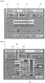
Fig. 8 is a diagram showing an example of other screen displayed on the monitor. -
Fig. 9 is a diagram showing an example of another screen displayed on the monitor. -
Fig. 10 is a diagram showing an example of condition setting with a mixture factor. -
Fig. 11 is a diagram showing an example of another screen displayed on the monitor. -
Fig. 12 is a diagram showing an example of yet another screen displayed on the monitor. - An embodiment of the present invention will hereinafter be described with reference to the drawings. As shown in
Fig. 1 , an imaging diagnostic system according to the present embodiment includes a medicalfluid injector device 100 and an imagingdiagnostic apparatus 300 interconnected thereto. Theinjector device 100 includes aninjector head 110 for injecting a contrast medium into a patient and acontroller unit 50 for programming conditions for the injection. - A known injector head can be used as the
injector head 110. In this example, a dual-type injector head may be used on which a syringe A (first syringe) filled with the contrast medium and a syringe B (second syringe) filled with physiological saline are configured to be mounted. - By way of example, the
injector head 110 is supported rotatably on a caster stand. Although not shown in detail, theinjector head 110 has piston driving mechanisms for pushing a piston member of each syringe. The piston driving mechanism is provided for each of syringes A and B. The piston driving mechanism has a motor serving as a driving source, a link mechanism for transferring force from the motor, and a member moving forward or rearward in response to the force transferred by the link mechanism. - The
injector head 110 may also have a tag reader for reading information stored on an IC tag attached to the syringe or a protective cover (not shown) thereof. The IC tag can store information about the syringe and information about the medical fluid in the syringe when the syringe is a pre-filled type. The information about the syringe may include, for example, identification data of a syringe (for example, a lot number), data of pressure limit of a cylinder member, data of an inner diameter of the cylinder member, and data of the stroke of the piston member. The information about medical fluid may include, for example, name of medical fluid (product name), content data including an iodine amount, viscosity, and expiration date. - As shown in
Fig. 1 , thecontroller unit 50 has amonitor 51 of a touch panel type. For example, images used for setting injection conditions are displayed on the monitor 51 (described later in detail). Information about medical fluid in the syringe, information about injection pressure of the medical fluid during medical fluid injection (force to push the piston member) and the like may also be displayed on themonitor 51. - The
controller unit 50 contains a computer component (not shown) which may perform: a process of receiving input of various information through the touch panel, a process of performing various calculations based on the input information, a process of controlling operations of theinjector head 110, and the like. The computer component may be a so-called one-chip microcomputer and may have hardware such as a CPU (Central Processing Unit), a ROM (Read Only Memory), a RAM (Random Access Memory), and an I/F (interface). In the computer component, some programs are stored on an information storage medium such as the ROM and the CPU performs various types of processing based on the program. - The
injector head 110 may be provided with a sub-monitor (not shown) of a touch panel type. A hand controller (not shown) may be connected to thecontroller unit 50, such that an operator can manipulate it for example to input some information. - The imaging
diagnostic apparatus 300 includes abed 303 movable horizontally with a patient lying thereon, anapparatus body 302 for taking diagnostic images of a patient, and a control unit (not shown) having a monitor, a keyboard and the like, by way of example. -
Fig. 2 shows a screen for setting injection conditions displayed on themonitor 51. On the screen, animage 20A representing the first syringe (contrast medium) is displayed in an upper portion of a central area on the screen. Animage 20B representing the second syringe (physiological saline) is displayed in a lower portion of the central area on the screen. - Three
images syringe images image 31, in this example, "3.0" (ml/sec) is displayed in a window. This means that the diluted contrast medium will be injected into a patient at a rate of 3.0 ml/sec. Theimage 31 functions as a button. As described later, when theimage 31 is pressed, anumeric keypad 41 will appear (seeFig. 4 ). Numeric values can be input through thenumeric keypad 41. - The volume of the diluted contrast medium is displayed in the
image 33, in this example, "20" (ml) is displayed in a window. This means that 20 ml of the diluted contrast medium will be injected into the patient. Similarly to theimage 31, theimage 33 also functions as a button. When theimage 33 is pressed, a numeric keypad similar to the abovementioned one will appear. - A mixture ratio of the contrast medium and the physiological saline is displayed in the
image 35, in this example, "50/50" is displayed. This means that the mixture ratio of the contrast medium and the physiological saline is 50:50 (1:1). Theimage 35 also functions as a button. Specifically, an operator can move his fingertip up or down (by way of example) while touching a portion ofimage 35, to thereby change the mixture ratio (described later in detail). - As shown in
Fig. 2 , the following images are displayed on the screen in addition to the abovementioned ones. Asection 24 for displaying an injection time shows a scheduled injection time, in this example, "0:07" (sec) is displayed. This means that medical fluid injection will be performed for 7 seconds. - An
information button 25 is displayed at the right on the screen. As shown inFig. 3 , when thebutton 25 is pressed, animage 37a showing the injection rate and the volume of the contrast medium, and animage 37b showing the injection rate and the volume of the physiological saline are displayed. In this example, the injection rate of the contrast medium is 1.5 ml/sec and the volume thereof is 10 ml. The injection rate of the physiological saline is 1.5 ml/sec and the volume thereof is 10 ml. - In the present embodiment, these information items (the injection rate and the volume of each medical fluid) will not be displayed unless the
information button 25 is pressed, by way of example. According to this configuration, the screen can be simplified such that only items relating to important information are displayed on the screen (seeFig. 2 ). This allows the operator to check the information on the screen easily. - Returning to the description of the images, as shown in
Fig. 2 , acircular indicator image 28 showing a pressure limit value is displayed at the lower left on the screen. In this example, "800" PSI is shown as the pressure limit value. Abutton 29 displaying "stand-by" is displayed at the upper right on the screen. - Operation of the medical
fluid injector device 100 of the present embodiment configured as above will be described below specifically. It should be noted that steps described below are merely illustrative and that the present invention is not limited to the order of the steps and the like. - First, the injection rate (3.0 mL/sec in this example) of the diluted contrast medium is input (see
Fig. 2 ). By way of example, this input may be performed by the operator selecting theimage 31 to shownumeric keypad 41 and inputting the numeric value through thenumeric keypad 41. Alternatively, theinjector head 110 may read the information stored on the IC tag attached to the syringe or the protective cover (not shown) thereof, and the information may be transmitted and automatically input to thecontroller unit 50. - Instead of the IC tag, magnet(s) and/or metal piece(s) that can represent predetermined information may be provided for the syringe or the protective cover.
- Simultaneously with or subsequently to (by way of example) the input of the injection rate, the volume of the diluted contrast medium (20 ml in this example) may be input. The input may be performed by the operator inputting the numeric value through the
numeric keypad 41 as shown inFig. 4 , similarly to the abovementioned input. Alternatively, theinjector head 110 may read the information stored on the IC tag attached to the syringe or the protective cover, and the information may be transmitted and automatically input to thecontroller unit 50. - Simultaneously with or subsequently to (by way of example) the input of the injection rate and the like, the mixture ratio (50:50 in this case) may be input. The input may be performed through automatic setting of a predetermined mixture ratio (50:50) as a default value. The operator can change the mixture ratio as required. To change the ratio, the operator can touch a part of
image 35 with his fingertip as shown inFig. 5 and move his fingertip up or down to change the mixture ratio. On a screen shown inFig. 5 , the mixture ratio is then changed to "60/40," by way of example. - After the input for the injection rate, the injection volume, and the mixture ratio is completed as described above, the
controller unit 50 performs: - a process of calculating the injection rate of the contrast medium (1.5 ml/sec) based on the input mixture ratio;
- a process of calculating the injection rate of the physiological saline (1.5 ml/sec) based on the input mixture ratio;
- a process of calculating the injection volume of the contrast medium (10 ml) based on the input mixture ratio; and
- a process of calculating the injection volume of the physiological saline (10 ml) based on the input mixture ratio.
- When the mixture ratio is changed, the
controller unit 50 performs: - a process of calculating the injection rate (1.8 ml/sec) of the contrast medium based on the changed mixture ratio;
- a process of calculating the injection rate (1.2 ml/sec) of the physiological saline based on the changed mixture ratio;
- a process of calculating the injection volume (12 ml) of the contrast medium based on the changed mixture ratio; and
- a process of calculating the injection volume (8 ml/sec) of the physiological saline based on the changed mixture ratio.
- After the setting of the injection conditions is completed through the abovementioned steps, the operator presses a stand-by button 29 (see
Fig. 2 ) at the upper right on the screen. Then a screen as shown inFig. 6 will appear.Fig. 6 shows an example of the screen in which the mixture ratio is 50:50. On the screen, anindicator 31a for visually displaying the injection rate is also displayed in theimage 31 showing the injection rate. "START OK" is displayed onbutton 29 at the upper right on the screen. - Next, the operator presses
button 29 of "START OK" or presses a certain button, not shown, on the injector head to start a medical fluid injection. Specifically, each piston driving mechanism of theinjector head 110 operates to inject each medical fluid at a predetermined injection rate (for example, 1.5 ml/sec) calculated through the abovementioned steps. In this example, the same volume of the medical fluids are pushed out from syringes A and B simultaneously to inject the patient with the diluted contrast medium provided by mixing the contrast medium and the physiological saline at the ratio of 1:1. - When the injection of 20 ml of diluted contrast medium is completed, the operation of the injector will be automatically finished.
- According to the medical fluid injector device of the present embodiment described above, a programming for injection conditions can be completed by inputting three numeric values, that is, the injection rate, the injection volume, and the mixture ratio of the diluted contrast medium. With such a configuration, injection conditions can be set more simply than an input method in which an injection rate and an injection volume need to be set respectively for each medical fluid.
- In the present invention, it is conceivable that a system will inject a contrast medium at predetermined mixture at a predetermined injection rate after inputting an injection rate of diluted contrast medium or a mixture ratio of the diluted contrast medium.
- The above embodiment has been described with the example in which the contrast medium and the physiological saline are injected, however, the present invention is not limited thereto. For example, two types of contrast medium may be mixed, or an anticancer drug may be diluted with physiological saline.
- Although the above embodiment has been described with the example in which the mixture ratio is changed by manipulating the screen (in
Fig. 2 , for example), such a change may additionally be performed through a voice input. This can be achieved by providing the medical fluid injector device with the unit of receiving voice input. According to the configuration, a doctor can change a mixture ratio without touching apparatus even during medical operation. - The present invention is not limited to the above embodiment, various modifications may be made. For example, as shown in
Fig. 7 , the mixture ratio may be changed during the medical operation (step S3a), after injection conditions for diluted contrast medium have been programmed (step S1) similarly to the above embodiment and then the injection (i.e. medical operation) has started (step S2). - In an angiography evaluation, the following procedure may be performed. A catheter is inserted into a predetermined region of interest (ROI) in a patient's body. Then, the diluted contrast medium of a certain concentration will be injected to examine the region. A tip of the catheter will be moved into a different region of interest, and a diluted contrast medium at a different concentration will be injected to examine the region. In such an examination, it is necessary to inject diluted contrast mediums at different concentrations during the medical operation. According to the configuration in which the mixture ratio can be changed during the procedure as in the present embodiment, diluted contrast medium at suitable concentration for each region of interest can be injected.
- As shown in
Fig. 7 , an injection rate of diluted contrast medium may be changed during medical operation (step S3b). For example, in order to change the injection rate the operator can manipulate the hand controller ofcontroller unit 50. Only the injection rate may be changed, while the mixture ratio is kept constant. - According to the configuration in which the injection rate can be changed during the medical injection, the contrast medium can be injected under conditions suitable for each region of interest similarly to the above case. It should be noted that the device according to the present invention may have only one of the functions described at step S3a and S3b.
- As other example, an image button may be displayed on the monitor of
controller unit 50, and when the button is pressed, the completion of the injection of the diluted contrast medium may be followed by subsequent injection of a predetermined volume of physiological saline. - According to this configuration, the contrast medium remaining in a tube or a catheter can be pushed by the saline. Specifically, the contrast medium remaining in the tube or the catheter can be injected into the patient at a desired pressure until all contrast medium is used, therefore the favorable visualization effect can be achieved to the end.
- As yet another example, it is possible to press an ANGIO button displayed at the upper left on the screen in
Fig. 2 to switch between a mode (A mode) in which only the contrast medium in syringe A is injected and a mode (B mode) in which only the physiological saline in syringe B is injected. More specifically, it is possible to press the button to switch A mode, B mode, and A+B mode in which the medical fluids in both syringes A and B are injected sequentially. - If a system does not have a mode for injecting only the medical fluid from one of the syringes, it would be necessary to program the mixture ratio from 50:50 (by way of example) to 100:0 (by way of example) in order to inject a contrast medium without dilution. Furthermore, after the injection, it would be necessary to program 50:50 (by way of example) to perform dilution injection. On the other hand, according to the system in which the modes are changeable described above, such an operation for changing the mixture ratio does not need to be performed, so that favorable usability is provided.
- It is conceivable that screens as shown in
Fig. 8 andFig. 9 may be displayed on the medical fluid injector device according to the present invention. In this example, twosyringe images 220A and 220B are displayed on the screen, similarly to the above embodiment. A scale, for example from 0 ml to 150 ml, showing a volume of medical fluid in the syringe is displayed betweensyringe images 220A and 220B. - On the screen, an
image 231 corresponding to theimage 31 in the above embodiment is displayed. An injection rate of diluted contrast medium is displayed in theimage 231, in this example, "3.0" (ml/sec) is displayed. Theimage 231 also functions as a button. When theimage 231 is pressed, a numeric keypad (not shown) appears. The numeric keypad can be manipulated to change the injection rate. - An
indicator 231a including a plurality of segments arranged horizontally is displayed in theimage 231. Theindicator 231a refers to a range of rates within which the system can be programmed. For example, assume that an upper limit of rate is 10 ml/sec, when a rate of 3.0 ml/sec is selected, 30% of all the segments will be displayed in a predetermined color.Such indicators 231a allow the operator to know intuitively a level of a currently set value relative to the upper limit value of rate. - As shown in
Fig. 8 , animage 233 corresponding to theimage 33 in the above embodiment is displayed on the screen. The injection volume of diluted contrast medium is displayed inimage 233, in this example, "20" (ml) is displayed. Theimage 233 also functions as a button similarly to theimage 231. When theimage 233 is pressed, a numeric keypad similar to the abovementioned one appears. An indicator similar to theindicator 231a described above is also displayed in theimage 233. - An image 235 (
Fig. 8 ) shows a mixture ratio of a contrast medium and a physiological saline. To change the mixture ratio, theimage 235 is pressed by the operator to display awindow 255 as shown inFig. 9 . A plurality of (10 in this example)color segments 255a arranged vertically are displayed inwindow 255 in addition to a numeric keypad and the like. Eachsegment 255a functions as a button. For example, if the operator selects thesegment 255a at the second from the top, then the mixture ratio will be programmed at 90:10. - A
slider 256 capable of sliding vertically on the screen is also displayed in thewindow 255. The mixture ratio can also be changed by moving theslider 256 vertically. - On the screen shown in
Fig. 8 , a plurality ofimage buttons 237 for setting a pressure limit value of medical fluid are displayed below the syringe image 220B, by way of example. The plurality ofimage buttons 237 are arranged in a line horizontally in this example. Twelveimage buttons 237 may be displayed and correspond to 1200, 1100, 1000, 900, 800, 700, 600, 500, 400, 300, 200, and 100 PSI in order from the left. Although not limited particularly, the numerals of the pressure limit values are displayed only onimage buttons 237 for 1200, 800, and 400 PSI, and no numerals are displayed on the other buttons. - The operator selects one of the
image buttons 237 to set the pressure limit value of medical fluid. As in a known control method, an alarm may be generated when a pressure of medical fluid during medical fluid injection exceeds a predetermined pressure limit, for example. Alternatively, the system may control its operation so that the medical fluid pressure can be reduced. - A screen as shown in
Fig. 10 may be displayed in the medical fluid injector device which screen is not a part of the present invention. In this example, injections conditions can be programmed by using a "mixture factor" instead of the "mixture ratio" as shown inFig. 2 . - A
factor display portion 351 extending vertically is displayed in awindow 355 as shown inFig. 10 . Numbers from 1 to 9 are displayed on the side of the display portion 351 (Number 6 to 8 are displayed by dots). The numbers represent mixture factors. - For example, the mixture factor "one" means that a contrast medium should be injected without dilution. The mixture factor "two" means that a contrast medium should be diluted by a factor of two (that is, the mixture ratio 50:50). To allow intuitive understanding of this, the number "2" is displayed substantially at the center of vertically extending
display portion 351. - The mixture factor "three" means that the contrast medium should be diluted by a factor of three (that is, the mixture ratio 1:2). To allow intuitive understanding of this, the number "3" is displayed at a position which divides the vertically extending display portion at a proportion of 1:2 (2 for the contrast medium). For
mixture factors 4 to 9, the numbers are also displayed at positions defined in the same manner. -
Horizontal lines 351a to 351h are displayed in association with the respective positions from thenumbers 2 to 9. A verticallyslidable slider 356 is displayed at the right of vertically extendingdisplay portion 351. The operator can touch and move theslider 356 vertically to select a desired mixture factor. The slider may be moved by touch with a finger or by an input pen or the like. - Although not limited particularly, the selected mixture factor is displayed as a character in an
image 235. In the example ofFig. 10 , "2 " is selected withslider 356, and "two-fold dilution" is displayed in theimage 335. - According to the configuration as shown in
Fig. 10 , since mixture conditions can be programmed based on the mixture factor , the doctor can use various setting methods, and a device with more favorable usability can be provided. - It goes without saying that the embodiment in which the mixture factor is input as shown in
Fig. 10 can be combined with other embodiments described above as appropriate. For example, the mixture factor may be input through voice input means. - Processes after inputting the mixture factor may be similar to those in the above embodiment. For example, when "three" is input as the mixture factor, an injection rate of contrast medium is calculated based on the mixture factor (by way of example, 1.0 ml/sec), whereas injection rate of physiological saline is calculated based on the mixture factor (by way of example, 2.0 ml/sec).
- With respect to a volume of mixed medical fluid being displayed as 20 ml in
Fig. 10 , for instance, when "three" is input as the mixture factor, the volume of contrast medium may be calculated based on that mixture factor (20 x 0.333 ... ml), whereas the injection rate of physiological saline may be calculated based on that mixture factor (20 x 0.666 ... ml). - Each medical fluid will be injected based on the injection rate and the injection volume calculated as described above.
- It should be noted that a numeric keypad might also be displayed in the
window 355 inFig. 10 . The mixture factor can also be set by directly inputting a numeric value through the numeric keypad. - Numeric values of the concentration for diluted medical fluid may be important in some situation in which contrast medium diluted with the physiological saline is injected. For example, a doctor sometimes needs specific concentration such as an iodine concentration of 370 mgI/ml to inject diluted contrast medium into a region of interest of the patient.
- To achieve this, it is conceivable that a system is configured to display a plurality of options for iodine concentration (for example, 400, 370, 350, 320, 300, 250, and 200 mgI/ml) on its screen. In response to selection of one of them, a specific injection rate of medical fluid will be automatically programmed so as to provide the diluted contrast medium having the selected iodine concentration.
- For example, assume that a contrast medium has an iodine concentration of 400 mgI/ml. In this case, when the operator selects 400 mgI/ml of the plurality of options, no dilution is needed and only the contrast medium is injected (that is, the injection at a mixture ratio of 0:100). When the operator selects 200 mgI/ml, for example, the injection rate and the injection volume of each medical fluid will be automatically changed so as to provide a mixture ratio of 50:50. The medical fluid injection will be performed under the reset conditions.
- According to the abovementioned configuration, since the injection conditions can be programmed by using the numeric value of the iodine concentration as a parameter, the medical fluid injector device can be provided with more favorable usability.
- It is conceivable that the hand controller of the controller unit may be manipulated to perform the following medical fluid injection. For example, during medical fluid injection at a certain mixture ratio (by way of example, 50:50), the hand controller can be used so as to change only the injection rate with the mixture ratio maintained. This allows favorable imaging suitable for each region of interest within the patient's body.
- Alternatively, it is possible to manipulate the hand controller during medical fluid injection to change only the mixture ratio with the injection rate maintained.
- Although the example of the present invention has been described, the present invention is not limited thereto, for example, input means such as a mouse and a keyboard may be used instead of the touch panel to input the predetermined information to
controller unit 50.Controller unit 50 may be connected to a network, and the information such as the injection rate and the injection volume of the diluted contrast medium may be input tocontroller unit 50 through the network. -
Fig. 11 shows an example of other screen displayed on the monitor. On this screen, abutton 238 "repeat" is displayed. Other icons (for example,images 231 and 233) are basically identical to those inFig. 8 , but "stand-by" is displayed onbutton 229 inFig. 11 . - The
repeat button 238 is used for repeatedly performing injections under the same conditions as the previous conditions. By way of example, assume that 20 ml of contrast medium is injected at a rate of 3.0 ml/sec in the previous injection and that a sufficient volume of medical fluid remains in the syringe after that injection. In this case, therepeat button 238 is pressed, and then the stand-by button 229 and a button, not shown, on the injector head are pressed to execute the injection under the same conditions as the previous conditions (at a rate of 3.0 ml/sec and a volume of 20 ml). Such a repeat injection is particularly useful for the procedure such as an angiography evaluation in which a relatively small volume of contrast medium is repeatedly injected. The repeat injection can be performed as long as the volume of medical fluid in the syringe is larger than a predetermined limit (20 ml in this example). - With respect to
Fig. 11 , it is conceived that a predetermined button "BACK" may be displayed on the screen when therepeat button 238 and the stand-by button 229 are pressed (the image "stand-by" is changed to "start OK"). This button can be pressed to return to the setting screen, and the injection conditions can be changed again on the setting screen. -
Fig. 12 shows an example of yet other screen displayed on the monitor. Although the injection rate and the injection volume are displayed by pressing theinformation button 25 in the mode shown inFig. 2 and the like, the present invention is not limited thereto. As shown inFig. 12 ,injection rate 231b of the medical fluid (by way of example, A: 1.5 ml/sec, B: 1.5 ml/sec) may be displayed in theimage 231, whereasinjection volume 233b of the medical fluid (by way of example, A: 10.0 ml, B: 10 ml) may be displayed in theimage 233. - In this case, switching may be made between the display mode as shown in
Fig. 12 and the mode usinginformation button 25 as shown inFig. 2 . -
- 25
- INFORMATION BUTTON
- 28
- INDICATOR IMAGE
- 31, 32, 33
- IMAGE BUTTON
- 35
- IMAGE (MIXTURE RATIO)
- 41
- NUMERIC KEYPAD
- 50
- CONTROLLER UNIT
- 51
- DISPLAY
- 110
- INJECTOR HEAD
- 231, 233
- IMAGE BUTTON
- 238
- REPEAT BUTTON
- 255
- WINDOW
- 300
- IMAGING DIAGNOSTIC APPARATUS
- 302
- APPARATUS BODY
- 303
- BED
- 355
- WINDOW
Claims (7)
- A medical fluid injector device, comprising:an injector head (110) injecting a patient with a mixed medical fluid provided by mixing a first medical fluid and a second medical fluid;a controller unit (50) having a monitor (51), screens for programming an injection condition for the mixed medical fluid displayed on the monitor,wherein the controller unit performs:a process of displaying a window (255) on the monitor that includes a plurality of color segments (255a) arranged vertically, wherein each color segment (255a) functions as a button to set a mixture ratio between the first medical fluid and the second medical fluid, and
a slider (256) being capable of sliding vertically to change the mixture ratio;a process of receiving an input relating to an injection rate of the mixed medical fluid;a process of receiving an input relating to the mixture ratio between the first medical fluid and the second medical fluid performed by an operator, wherein the input is performed by pressing a color segment (255a) or moving the slider (256) to select predetermined mixture ratio;a process of calculating the injection rate of the first medical fluid based on said input mixture ratio;a process of calculating the injection rate of the second medical fluid based on said input mixture ratio;and wherein the injector head injects the first medical fluid at the calculated injection rate of the first medical fluid and the second medical fluid at the calculated injection rate of the second medical fluid. - The medical fluid injector device according to claim 1, wherein the monitor is of a touch panel type, and
in the process of receiving an input relating to a mixture ratio, an image button for changing the mixture ratio is displayed on the monitor, and the mixture ratio is changed by the operator moving his fingertip or an input pen while he touches the image button with his fingertip or the input pen. - The medical fluid injector device according to claim 1 or 2, wherein the controller unit further performs:a process of receiving an input relating the volume of mixed medical fluid;a process of calculating the volume of the first medical fluid based on the input mixture ratio; anda process of calculating the volume of the second medical fluid based on the input mixture ratio.
- The medical fluid injector device according to any one of claims 1 to 3, wherein the controller further performs:a process of receiving a change, made by the operator, relating to the mixture ratioduring injection of the mixed medical fluid;a process of calculating an injection rate of the first medical fluid based on the new mixture ratio; anda process of calculating an injection rate of the second medical fluid based on the new mixture ratio, andthe injector head injects the first medical fluid and the second medical fluid at the calculated new injection rate of the first medical fluid and the calculated new injection rate of the second medical fluid, respectively.
- The medical fluid injector device according to claim 3, wherein the controller unit further performs a process of displaying the injection rate of the mixed medical fluid and the injection volume of the mixed medical fluid on the monitor.
- The medical fluid injector device according to claim 5, wherein, when a predetermined image button displayed on the monitor is pressed, the controller unit performs a process of displaying, on the monitor:the calculated injection rate and the calculated volume of the first medical fluid; andthe calculated injection rate and the calculated volume of the second medical fluid.
- The medical fluid injector device according to any one of claims 1 to 6, wherein the controller unit includes a voice input function, to allow the operator to input a mixture ratio with voice.
Priority Applications (1)
| Application Number | Priority Date | Filing Date | Title |
|---|---|---|---|
| EP21154528.0A EP3851137A1 (en) | 2010-04-06 | 2011-04-04 | Medical fluid injector device |
Applications Claiming Priority (2)
| Application Number | Priority Date | Filing Date | Title |
|---|---|---|---|
| JP2010087882 | 2010-04-06 | ||
| PCT/JP2011/058557 WO2011125987A1 (en) | 2010-04-06 | 2011-04-04 | Drug solution injection device |
Related Child Applications (1)
| Application Number | Title | Priority Date | Filing Date |
|---|---|---|---|
| EP21154528.0A Division EP3851137A1 (en) | 2010-04-06 | 2011-04-04 | Medical fluid injector device |
Publications (3)
| Publication Number | Publication Date |
|---|---|
| EP2556851A1 EP2556851A1 (en) | 2013-02-13 |
| EP2556851A4 EP2556851A4 (en) | 2016-11-09 |
| EP2556851B1 true EP2556851B1 (en) | 2021-02-24 |
Family
ID=44762922
Family Applications (2)
| Application Number | Title | Priority Date | Filing Date |
|---|---|---|---|
| EP21154528.0A Pending EP3851137A1 (en) | 2010-04-06 | 2011-04-04 | Medical fluid injector device |
| EP11765887.2A Active EP2556851B1 (en) | 2010-04-06 | 2011-04-04 | Drug solution injection device |
Family Applications Before (1)
| Application Number | Title | Priority Date | Filing Date |
|---|---|---|---|
| EP21154528.0A Pending EP3851137A1 (en) | 2010-04-06 | 2011-04-04 | Medical fluid injector device |
Country Status (5)
| Country | Link |
|---|---|
| US (2) | US9675749B2 (en) |
| EP (2) | EP3851137A1 (en) |
| JP (1) | JP6093178B2 (en) |
| CN (2) | CN106110431B (en) |
| WO (1) | WO2011125987A1 (en) |
Families Citing this family (15)
| Publication number | Priority date | Publication date | Assignee | Title |
|---|---|---|---|---|
| US11369739B2 (en) * | 2013-01-21 | 2022-06-28 | Medline Industries, Lp | Method to provide injection system parameters for injecting fluid into patient |
| JP6792104B2 (en) * | 2015-06-24 | 2020-11-25 | 株式会社根本杏林堂 | Chemical injection device |
| WO2017152036A1 (en) | 2016-03-03 | 2017-09-08 | Bayer Healthcare Llc | System and method for improved fluid delivery in multi-fluid injector systems |
| JP7051076B2 (en) * | 2016-08-26 | 2022-04-11 | 株式会社根本杏林堂 | Chemical injection device |
| US20200030524A1 (en) * | 2017-04-12 | 2020-01-30 | Nemoto Kyorindo Co., Ltd. | Chemical liquid injector |
| CN110869071B (en) * | 2017-08-31 | 2023-05-02 | 拜耳医药保健有限公司 | Method of dynamic pressure control in a fluid injector system |
| US11598664B2 (en) | 2017-08-31 | 2023-03-07 | Bayer Healthcare Llc | Injector pressure calibration system and method |
| CA3067740A1 (en) | 2017-08-31 | 2019-03-07 | Bayer Healthcare Llc | Method for drive member position and fluid injection system mechanical calibration |
| WO2019046299A1 (en) | 2017-08-31 | 2019-03-07 | Bayer Healthcare Llc | Fluid path impedance assessment for improving fluid delivery performance |
| JP7201245B2 (en) * | 2017-11-24 | 2023-01-10 | 株式会社根本杏林堂 | Injection head and chemical injection device provided with the same |
| WO2019111995A1 (en) * | 2017-12-08 | 2019-06-13 | 株式会社根本杏林堂 | Drug solution infusion device |
| JP7007178B2 (en) * | 2017-12-25 | 2022-01-24 | 日本光電工業株式会社 | Anesthetic machine |
| JPWO2020162596A1 (en) * | 2019-02-08 | 2021-12-09 | 株式会社サーキュラス | Chemical injection device and chemical injection system |
| CN112007239B (en) * | 2020-09-24 | 2021-06-04 | 浙江迈帝康医疗器械有限公司 | Injection pump |
| DE102021104411A1 (en) * | 2021-02-24 | 2022-08-25 | B. Braun Melsungen Aktiengesellschaft | Device and method for administering liquids |
Citations (1)
| Publication number | Priority date | Publication date | Assignee | Title |
|---|---|---|---|---|
| US20060079768A1 (en) * | 2004-10-13 | 2006-04-13 | Liebel-Flarsheim Company | Powerhead control in a power injection system |
Family Cites Families (25)
| Publication number | Priority date | Publication date | Assignee | Title |
|---|---|---|---|---|
| US5840026A (en) | 1994-09-21 | 1998-11-24 | Medrad, Inc. | Patient specific dosing contrast delivery systems and methods |
| US5881723A (en) * | 1997-03-14 | 1999-03-16 | Nellcor Puritan Bennett Incorporated | Ventilator breath display and graphic user interface |
| JP2001149360A (en) * | 1999-11-25 | 2001-06-05 | Toshiba Corp | X-ray diagnostic system |
| JP3949912B2 (en) * | 2000-08-08 | 2007-07-25 | 株式会社エヌ・ティ・ティ・ドコモ | Portable electronic device, electronic device, vibration generator, notification method by vibration and notification control method |
| JP4975208B2 (en) * | 2000-10-03 | 2012-07-11 | 株式会社根本杏林堂 | Automatic injection equipment |
| US7553294B2 (en) | 2002-05-30 | 2009-06-30 | Medrad, Inc. | Syringe plunger sensing mechanism for a medical injector |
| JP4417621B2 (en) * | 2002-12-16 | 2010-02-17 | 株式会社根本杏林堂 | Chemical injection device |
| CN1738656A (en) * | 2002-12-23 | 2006-02-22 | M2医药有限公司 | Disposable, wearable insulin dispensing device, a combination of such a device and a programming controller and a method of controlling the operation of such a device |
| JP4731795B2 (en) * | 2003-02-18 | 2011-07-27 | 株式会社根本杏林堂 | Chemical injection device |
| EP1647291A4 (en) * | 2003-07-18 | 2007-06-06 | Nemoto Kyorindo Co Ltd | Medicine infuser for displaying image of entered infusion condition |
| JP2005131007A (en) * | 2003-10-29 | 2005-05-26 | Nemoto Kyorindo:Kk | Medical fluid injection system |
| US7552731B2 (en) * | 2003-11-14 | 2009-06-30 | Remcore, Inc. | Remote control gas regulation system |
| ITMO20040028A1 (en) * | 2004-02-06 | 2004-05-06 | Sidam Di Azzolini Graziano E C | SYRINGE INFUSION PUMP |
| WO2005118031A1 (en) | 2004-05-27 | 2005-12-15 | E-Z-Em, Inc. | System, method, and computer program product for handling, mixing, dispensing, and injecting radiopharmaceutical agents |
| JP5232473B2 (en) | 2004-11-24 | 2013-07-10 | メドラッド インコーポレーテッド | System and apparatus for modeling the pressure generated during an injection process |
| US7766883B2 (en) * | 2007-10-30 | 2010-08-03 | Medrad, Inc. | System and method for proportional mixing and continuous delivery of fluids |
| CN101400325A (en) * | 2006-02-01 | 2009-04-01 | 脊柱修复公司 | Fibrin sealant delivery device including pressure monitoring, and methods and kits thereof |
| WO2007116840A1 (en) | 2006-04-04 | 2007-10-18 | Nemoto Kyorindo Co., Ltd. | Drug solution injector |
| US7674244B2 (en) * | 2006-05-23 | 2010-03-09 | Medrad, Inc. | Devices, systems and methods for detecting increase fluid levels in tissue |
| EP3376504A1 (en) * | 2006-12-29 | 2018-09-19 | Bayer Healthcare, LLC | Patient-based parameter generation systems for medical injection procedures |
| US9056164B2 (en) * | 2007-01-01 | 2015-06-16 | Bayer Medical Care Inc. | Radiopharmaceutical administration methods, fluid delivery systems and components thereof |
| KR20080079007A (en) * | 2007-02-26 | 2008-08-29 | 삼성전자주식회사 | Electronic device for inputting user command |
| JP2009089817A (en) * | 2007-10-05 | 2009-04-30 | Nemoto Kyorindo:Kk | Medical solution injector |
| JP5815241B2 (en) * | 2007-11-19 | 2015-11-17 | リーベル−フラーシャイム カンパニー エルエルシー | Power injector with status messaging |
| CN201168125Y (en) * | 2008-03-20 | 2008-12-24 | 王素云 | Disposal emergency infusion bag |
-
2011
- 2011-04-04 WO PCT/JP2011/058557 patent/WO2011125987A1/en active Application Filing
- 2011-04-04 EP EP21154528.0A patent/EP3851137A1/en active Pending
- 2011-04-04 CN CN201610570632.0A patent/CN106110431B/en active Active
- 2011-04-04 US US13/639,657 patent/US9675749B2/en active Active
- 2011-04-04 EP EP11765887.2A patent/EP2556851B1/en active Active
- 2011-04-04 JP JP2012509657A patent/JP6093178B2/en active Active
- 2011-04-04 CN CN2011800279283A patent/CN102933241A/en active Pending
-
2017
- 2017-05-16 US US15/596,591 patent/US20170246378A1/en not_active Abandoned
Patent Citations (1)
| Publication number | Priority date | Publication date | Assignee | Title |
|---|---|---|---|---|
| US20060079768A1 (en) * | 2004-10-13 | 2006-04-13 | Liebel-Flarsheim Company | Powerhead control in a power injection system |
Also Published As
| Publication number | Publication date |
|---|---|
| CN106110431B (en) | 2020-08-04 |
| EP3851137A1 (en) | 2021-07-21 |
| JPWO2011125987A1 (en) | 2013-07-11 |
| CN102933241A (en) | 2013-02-13 |
| EP2556851A1 (en) | 2013-02-13 |
| US20130030290A1 (en) | 2013-01-31 |
| US9675749B2 (en) | 2017-06-13 |
| JP6093178B2 (en) | 2017-03-08 |
| CN106110431A (en) | 2016-11-16 |
| EP2556851A4 (en) | 2016-11-09 |
| WO2011125987A1 (en) | 2011-10-13 |
| US20170246378A1 (en) | 2017-08-31 |
Similar Documents
| Publication | Publication Date | Title |
|---|---|---|
| EP2556851B1 (en) | Drug solution injection device | |
| JP6844867B2 (en) | Chemical injection device | |
| JP7010513B2 (en) | Chemical injection device and chemical injection system | |
| US9827368B2 (en) | Liquid injector with appropriate operating conditions set by selecting displayed image | |
| US7844328B2 (en) | Liquid injector for controlling injection of liquid in real-time according to injection graph | |
| US20070083152A1 (en) | Method and System for Implementing a Graphical User Interface for a Multi-Fluid Injection Device | |
| CA2722991A1 (en) | Workflow driven user interface for medical fluid delivery systems | |
| JP5770638B2 (en) | Chemical injection system | |
| WO2020158809A1 (en) | Liquid medicine injection device for angiograms | |
| JP2020124598A (en) | Chemical injection device |
Legal Events
| Date | Code | Title | Description |
|---|---|---|---|
| PUAI | Public reference made under article 153(3) epc to a published international application that has entered the european phase |
Free format text: ORIGINAL CODE: 0009012 |
|
| 17P | Request for examination filed |
Effective date: 20121106 |
|
| AK | Designated contracting states |
Kind code of ref document: A1 Designated state(s): AL AT BE BG CH CY CZ DE DK EE ES FI FR GB GR HR HU IE IS IT LI LT LU LV MC MK MT NL NO PL PT RO RS SE SI SK SM TR |
|
| DAX | Request for extension of the european patent (deleted) | ||
| RA4 | Supplementary search report drawn up and despatched (corrected) |
Effective date: 20161011 |
|
| RIC1 | Information provided on ipc code assigned before grant |
Ipc: A61M 5/142 20060101ALI20161005BHEP Ipc: A61M 5/145 20060101ALI20161005BHEP Ipc: A61M 5/00 20060101AFI20161005BHEP Ipc: A61M 5/168 20060101ALI20161005BHEP |
|
| STAA | Information on the status of an ep patent application or granted ep patent |
Free format text: STATUS: EXAMINATION IS IN PROGRESS |
|
| 17Q | First examination report despatched |
Effective date: 20181009 |
|
| GRAP | Despatch of communication of intention to grant a patent |
Free format text: ORIGINAL CODE: EPIDOSNIGR1 |
|
| STAA | Information on the status of an ep patent application or granted ep patent |
Free format text: STATUS: GRANT OF PATENT IS INTENDED |
|
| INTG | Intention to grant announced |
Effective date: 20200916 |
|
| GRAS | Grant fee paid |
Free format text: ORIGINAL CODE: EPIDOSNIGR3 |
|
| GRAA | (expected) grant |
Free format text: ORIGINAL CODE: 0009210 |
|
| STAA | Information on the status of an ep patent application or granted ep patent |
Free format text: STATUS: THE PATENT HAS BEEN GRANTED |
|
| AK | Designated contracting states |
Kind code of ref document: B1 Designated state(s): AL AT BE BG CH CY CZ DE DK EE ES FI FR GB GR HR HU IE IS IT LI LT LU LV MC MK MT NL NO PL PT RO RS SE SI SK SM TR |
|
| REG | Reference to a national code |
Ref country code: GB Ref legal event code: FG4D |
|
| REG | Reference to a national code |
Ref country code: CH Ref legal event code: EP |
|
| REG | Reference to a national code |
Ref country code: AT Ref legal event code: REF Ref document number: 1363675 Country of ref document: AT Kind code of ref document: T Effective date: 20210315 |
|
| REG | Reference to a national code |
Ref country code: IE Ref legal event code: FG4D |
|
| REG | Reference to a national code |
Ref country code: DE Ref legal event code: R096 Ref document number: 602011070225 Country of ref document: DE |
|
| REG | Reference to a national code |
Ref country code: LT Ref legal event code: MG9D |
|
| REG | Reference to a national code |
Ref country code: NL Ref legal event code: MP Effective date: 20210224 |
|
| PG25 | Lapsed in a contracting state [announced via postgrant information from national office to epo] |
Ref country code: FI Free format text: LAPSE BECAUSE OF FAILURE TO SUBMIT A TRANSLATION OF THE DESCRIPTION OR TO PAY THE FEE WITHIN THE PRESCRIBED TIME-LIMIT Effective date: 20210224 Ref country code: GR Free format text: LAPSE BECAUSE OF FAILURE TO SUBMIT A TRANSLATION OF THE DESCRIPTION OR TO PAY THE FEE WITHIN THE PRESCRIBED TIME-LIMIT Effective date: 20210525 Ref country code: HR Free format text: LAPSE BECAUSE OF FAILURE TO SUBMIT A TRANSLATION OF THE DESCRIPTION OR TO PAY THE FEE WITHIN THE PRESCRIBED TIME-LIMIT Effective date: 20210224 Ref country code: LT Free format text: LAPSE BECAUSE OF FAILURE TO SUBMIT A TRANSLATION OF THE DESCRIPTION OR TO PAY THE FEE WITHIN THE PRESCRIBED TIME-LIMIT Effective date: 20210224 Ref country code: PT Free format text: LAPSE BECAUSE OF FAILURE TO SUBMIT A TRANSLATION OF THE DESCRIPTION OR TO PAY THE FEE WITHIN THE PRESCRIBED TIME-LIMIT Effective date: 20210624 Ref country code: BG Free format text: LAPSE BECAUSE OF FAILURE TO SUBMIT A TRANSLATION OF THE DESCRIPTION OR TO PAY THE FEE WITHIN THE PRESCRIBED TIME-LIMIT Effective date: 20210524 Ref country code: NO Free format text: LAPSE BECAUSE OF FAILURE TO SUBMIT A TRANSLATION OF THE DESCRIPTION OR TO PAY THE FEE WITHIN THE PRESCRIBED TIME-LIMIT Effective date: 20210524 |
|
| REG | Reference to a national code |
Ref country code: AT Ref legal event code: MK05 Ref document number: 1363675 Country of ref document: AT Kind code of ref document: T Effective date: 20210224 |
|
| PG25 | Lapsed in a contracting state [announced via postgrant information from national office to epo] |
Ref country code: SE Free format text: LAPSE BECAUSE OF FAILURE TO SUBMIT A TRANSLATION OF THE DESCRIPTION OR TO PAY THE FEE WITHIN THE PRESCRIBED TIME-LIMIT Effective date: 20210224 Ref country code: NL Free format text: LAPSE BECAUSE OF FAILURE TO SUBMIT A TRANSLATION OF THE DESCRIPTION OR TO PAY THE FEE WITHIN THE PRESCRIBED TIME-LIMIT Effective date: 20210224 Ref country code: RS Free format text: LAPSE BECAUSE OF FAILURE TO SUBMIT A TRANSLATION OF THE DESCRIPTION OR TO PAY THE FEE WITHIN THE PRESCRIBED TIME-LIMIT Effective date: 20210224 Ref country code: PL Free format text: LAPSE BECAUSE OF FAILURE TO SUBMIT A TRANSLATION OF THE DESCRIPTION OR TO PAY THE FEE WITHIN THE PRESCRIBED TIME-LIMIT Effective date: 20210224 Ref country code: LV Free format text: LAPSE BECAUSE OF FAILURE TO SUBMIT A TRANSLATION OF THE DESCRIPTION OR TO PAY THE FEE WITHIN THE PRESCRIBED TIME-LIMIT Effective date: 20210224 |
|
| PG25 | Lapsed in a contracting state [announced via postgrant information from national office to epo] |
Ref country code: IS Free format text: LAPSE BECAUSE OF FAILURE TO SUBMIT A TRANSLATION OF THE DESCRIPTION OR TO PAY THE FEE WITHIN THE PRESCRIBED TIME-LIMIT Effective date: 20210624 |
|
| PG25 | Lapsed in a contracting state [announced via postgrant information from national office to epo] |
Ref country code: SM Free format text: LAPSE BECAUSE OF FAILURE TO SUBMIT A TRANSLATION OF THE DESCRIPTION OR TO PAY THE FEE WITHIN THE PRESCRIBED TIME-LIMIT Effective date: 20210224 Ref country code: AT Free format text: LAPSE BECAUSE OF FAILURE TO SUBMIT A TRANSLATION OF THE DESCRIPTION OR TO PAY THE FEE WITHIN THE PRESCRIBED TIME-LIMIT Effective date: 20210224 Ref country code: CZ Free format text: LAPSE BECAUSE OF FAILURE TO SUBMIT A TRANSLATION OF THE DESCRIPTION OR TO PAY THE FEE WITHIN THE PRESCRIBED TIME-LIMIT Effective date: 20210224 Ref country code: EE Free format text: LAPSE BECAUSE OF FAILURE TO SUBMIT A TRANSLATION OF THE DESCRIPTION OR TO PAY THE FEE WITHIN THE PRESCRIBED TIME-LIMIT Effective date: 20210224 |
|
| REG | Reference to a national code |
Ref country code: DE Ref legal event code: R097 Ref document number: 602011070225 Country of ref document: DE |
|
| PG25 | Lapsed in a contracting state [announced via postgrant information from national office to epo] |
Ref country code: RO Free format text: LAPSE BECAUSE OF FAILURE TO SUBMIT A TRANSLATION OF THE DESCRIPTION OR TO PAY THE FEE WITHIN THE PRESCRIBED TIME-LIMIT Effective date: 20210224 Ref country code: ES Free format text: LAPSE BECAUSE OF FAILURE TO SUBMIT A TRANSLATION OF THE DESCRIPTION OR TO PAY THE FEE WITHIN THE PRESCRIBED TIME-LIMIT Effective date: 20210224 Ref country code: DK Free format text: LAPSE BECAUSE OF FAILURE TO SUBMIT A TRANSLATION OF THE DESCRIPTION OR TO PAY THE FEE WITHIN THE PRESCRIBED TIME-LIMIT Effective date: 20210224 Ref country code: SK Free format text: LAPSE BECAUSE OF FAILURE TO SUBMIT A TRANSLATION OF THE DESCRIPTION OR TO PAY THE FEE WITHIN THE PRESCRIBED TIME-LIMIT Effective date: 20210224 Ref country code: MC Free format text: LAPSE BECAUSE OF FAILURE TO SUBMIT A TRANSLATION OF THE DESCRIPTION OR TO PAY THE FEE WITHIN THE PRESCRIBED TIME-LIMIT Effective date: 20210224 |
|
| PG25 | Lapsed in a contracting state [announced via postgrant information from national office to epo] |
Ref country code: LU Free format text: LAPSE BECAUSE OF NON-PAYMENT OF DUE FEES Effective date: 20210404 |
|
| PLBE | No opposition filed within time limit |
Free format text: ORIGINAL CODE: 0009261 |
|
| STAA | Information on the status of an ep patent application or granted ep patent |
Free format text: STATUS: NO OPPOSITION FILED WITHIN TIME LIMIT |
|
| REG | Reference to a national code |
Ref country code: BE Ref legal event code: MM Effective date: 20210430 |
|
| PG25 | Lapsed in a contracting state [announced via postgrant information from national office to epo] |
Ref country code: AL Free format text: LAPSE BECAUSE OF FAILURE TO SUBMIT A TRANSLATION OF THE DESCRIPTION OR TO PAY THE FEE WITHIN THE PRESCRIBED TIME-LIMIT Effective date: 20210224 Ref country code: CH Free format text: LAPSE BECAUSE OF NON-PAYMENT OF DUE FEES Effective date: 20210430 Ref country code: LI Free format text: LAPSE BECAUSE OF NON-PAYMENT OF DUE FEES Effective date: 20210430 |
|
| 26N | No opposition filed |
Effective date: 20211125 |
|
| PG25 | Lapsed in a contracting state [announced via postgrant information from national office to epo] |
Ref country code: SI Free format text: LAPSE BECAUSE OF FAILURE TO SUBMIT A TRANSLATION OF THE DESCRIPTION OR TO PAY THE FEE WITHIN THE PRESCRIBED TIME-LIMIT Effective date: 20210224 |
|
| PG25 | Lapsed in a contracting state [announced via postgrant information from national office to epo] |
Ref country code: IT Free format text: LAPSE BECAUSE OF FAILURE TO SUBMIT A TRANSLATION OF THE DESCRIPTION OR TO PAY THE FEE WITHIN THE PRESCRIBED TIME-LIMIT Effective date: 20210224 Ref country code: IE Free format text: LAPSE BECAUSE OF NON-PAYMENT OF DUE FEES Effective date: 20210404 |
|
| PG25 | Lapsed in a contracting state [announced via postgrant information from national office to epo] |
Ref country code: IS Free format text: LAPSE BECAUSE OF FAILURE TO SUBMIT A TRANSLATION OF THE DESCRIPTION OR TO PAY THE FEE WITHIN THE PRESCRIBED TIME-LIMIT Effective date: 20210624 |
|
| PG25 | Lapsed in a contracting state [announced via postgrant information from national office to epo] |
Ref country code: BE Free format text: LAPSE BECAUSE OF NON-PAYMENT OF DUE FEES Effective date: 20210430 |
|
| PGFP | Annual fee paid to national office [announced via postgrant information from national office to epo] |
Ref country code: FR Payment date: 20230330 Year of fee payment: 13 |
|
| PG25 | Lapsed in a contracting state [announced via postgrant information from national office to epo] |
Ref country code: HU Free format text: LAPSE BECAUSE OF FAILURE TO SUBMIT A TRANSLATION OF THE DESCRIPTION OR TO PAY THE FEE WITHIN THE PRESCRIBED TIME-LIMIT; INVALID AB INITIO Effective date: 20110404 Ref country code: CY Free format text: LAPSE BECAUSE OF FAILURE TO SUBMIT A TRANSLATION OF THE DESCRIPTION OR TO PAY THE FEE WITHIN THE PRESCRIBED TIME-LIMIT Effective date: 20210224 |
|
| PGFP | Annual fee paid to national office [announced via postgrant information from national office to epo] |
Ref country code: DE Payment date: 20230408 Year of fee payment: 13 |
|
| PGFP | Annual fee paid to national office [announced via postgrant information from national office to epo] |
Ref country code: GB Payment date: 20230424 Year of fee payment: 13 |