EP2556265B1 - Getriebe mit kupplung - Google Patents
Getriebe mit kupplung Download PDFInfo
- Publication number
- EP2556265B1 EP2556265B1 EP11710701.1A EP11710701A EP2556265B1 EP 2556265 B1 EP2556265 B1 EP 2556265B1 EP 11710701 A EP11710701 A EP 11710701A EP 2556265 B1 EP2556265 B1 EP 2556265B1
- Authority
- EP
- European Patent Office
- Prior art keywords
- switching
- gear mechanism
- cam
- switching element
- switching cam
- Prior art date
- Legal status (The legal status is an assumption and is not a legal conclusion. Google has not performed a legal analysis and makes no representation as to the accuracy of the status listed.)
- Active
Links
Images


Classifications
-
- F—MECHANICAL ENGINEERING; LIGHTING; HEATING; WEAPONS; BLASTING
- F16—ENGINEERING ELEMENTS AND UNITS; GENERAL MEASURES FOR PRODUCING AND MAINTAINING EFFECTIVE FUNCTIONING OF MACHINES OR INSTALLATIONS; THERMAL INSULATION IN GENERAL
- F16D—COUPLINGS FOR TRANSMITTING ROTATION; CLUTCHES; BRAKES
- F16D11/00—Clutches in which the members have interengaging parts
- F16D11/14—Clutches in which the members have interengaging parts with clutching members movable only axially
-
- F—MECHANICAL ENGINEERING; LIGHTING; HEATING; WEAPONS; BLASTING
- F16—ENGINEERING ELEMENTS AND UNITS; GENERAL MEASURES FOR PRODUCING AND MAINTAINING EFFECTIVE FUNCTIONING OF MACHINES OR INSTALLATIONS; THERMAL INSULATION IN GENERAL
- F16D—COUPLINGS FOR TRANSMITTING ROTATION; CLUTCHES; BRAKES
- F16D11/00—Clutches in which the members have interengaging parts
- F16D2011/002—Clutches in which the members have interengaging parts using an external and axially slidable sleeve for coupling the teeth of both coupling components together
Definitions
- the invention relates to a transmission with a clutch, a trolley and a monorail.
- the invention has the object of developing a transmission with clutch, the clutch safely switches, is easy to operate and compact builds.
- the clutch has a switching cam, a switching element and a spring element, wherein the switching element by rotating the switching cam about the axis of rotation of the switching cam between at least two switching positions against or with a force acting on the switching element spring force of the spring element and is movable forth, wherein the switching cam two Buttons, and the buttons with the switching element cooperate such that the amount of force acting on the switching element spring force in response to the rotation angle of rotation in each switching position assumes a local minimum.
- the advantage here is that the switching positions are kept safe, the clutch is easy to operate and can also be installed in compact gear.
- the switching cam interacts with the switching element such that upon rotation of the switching cam on the switching element between the at least two switching positions at least one rotational position of the switching cam, a maximum spring force acts, which is greater than the local minimums of the spring force of the switching positions.
- the two buttons correspond to a surface of the switching element, wherein in one of the at least two switching states presses the corresponding button against the surface.
- the associated button in a second of the at least two switching states, is spaced parallel to approximately parallel from the surface.
- the two buttons are arranged on an end portion of the switching cam.
- the advantage here is that the coupling is easy to assemble.
- the switching cam is substantially cylindrical.
- the advantage here is that the coupling is very compact.
- buttons are arranged flat and / or parallel to the axis of rotation.
- the advantage here is that the coupling is easy to manufacture.
- buttons are arranged at an angle to each other, preferably arranged substantially perpendicular to each other.
- the end region forms a cylinder section, from which two disk segments are excluded to form the buttons at a free end of the end region.
- a lead-through region of the switching cam adjoins the end region, which has a groove extending radially around the rotational axis for receiving a sealing element, in particular an O-ring.
- the switching element by the rotation of the switching cam in a direction perpendicular to the rotational axis of the switching cam between a Einkuppelposition and a disengaged position is movable back and forth.
- the advantage here is that the clutch is compact and easy to assemble.
- the switching element is rotatably and axially displaceable connected to a shaft of the transmission.
- the advantage here is that the clutch switches safely because the switching element is guided safely.
- the switching element with a gear of the transmission preferably form-fitting, rotatably connected and released again.
- the advantage here is that the coupling is easy and safe to install in a transmission.
- the switching cam in particular with its feedthrough section, in a housing wall a housing of the transmission is held, wherein the buttons and the switching element are arranged in an interior of the housing.
- the advantage here is that the coupling is easily integrated into the transmission and safely switches.
- the transmission rotatably and axially slidably disposed, wherein the spring force, the switching element in the direction of a gear which is rotatably mounted on the shaft, presses, wherein the switching element rotatably connected in the engaged state with the gear is, in particular claws of the switching element and corresponding claws in an end face of the gear mesh with each other.
- a shift lever is arranged on the control cam outside of the transmission housing, with which the switching cam is rotated, in particular wherein a force component from the switching cam on the switching element, which is caused by the weight of the shift lever, in each position of the transmission is smaller than the spring force on the switching element.
- a trolley for a monorail system with a transmission that the transmission is driven by a motor of the trolley and an impeller of the trolley is rotatably connected to the shaft of the transmission.
- the advantage here is that the transmission is easy to operate by hand.
- a trolley described above is used.
- the advantage here is that the electric monorail system is safe to operate.
- a further advantage is that a conveyor unit of the electric monorail system with a trolley, which has a transmission described above with a clutch according to the invention in a power failure safely remains in the position and is freely displaced only by operating the clutch.
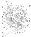
- a clutch 12 according to the invention is shown in a transmission 10.
- the transmission 10 comprises a housing 48, which encloses an interior space 50.
- the housing 48 has a cover 58, a Eintriebsflansch 60 and a driven flange 62.
- At Eintriebsflansch 60 for example, a not shown electric motor is flanged.
- At the output flange 62 for example, a drive wheel unit, not shown, for an overhead monorail can be attached.
- the transmission 10 further includes a pinion which meshes with a gear 44 of the transmission 10.
- the pinion and the gear 44 are arranged in the housing 48.
- the shaft 42 is designed in particular as an output shaft.
- a stub shaft 64 of the output shaft protrudes through the output flange 62 out of the housing 48.
- the gear 44 is rotatably mounted on the shaft 42 of the transmission 10. To switch between a rotationally fixed state and a mutually rotatable state of the shaft 42 relative to the gear 44, the transmission 10, the clutch 12 on.
- the clutch 12 has a switching cam 14, a switching element 16 and a spring element 18.
- the switching element 16 is rotatably, but axially displaceably arranged on the shaft 42.
- the switching element 16 is preferably designed as a pipe section 68 which surrounds the shaft 42.
- the pipe section 68 for example an internal toothing, which engages in a toothing on the shaft 42, so that thereby the switching element 16 on the shaft 42 is axially displaceable.
- the internal teeth and the teeth are designed so that they remain in any possible axial position of the switching element 16 at least partially engaged.
- the toothed ridges of the toothing and the internal toothing extend in the axial direction.
- the pipe section 68 has a flange-like collar 66, which is designed in one piece with the pipe section 68.
- the flange-like collar forms an executed to gear 44 surface 22 and is preferably perpendicular to the axis of the shaft 42.
- the surface 22 has in the in FIG. 1 embodiment shown in the form of a ring.
- the gear 44 directed to the front side of the pipe section 68 has jaws 52. At the end face 56 of the toothed wheel 44 directed to the switching element 16, corresponding claws 54 are formed. By axially pushing the switching element 16 back and forth, the clutch 12 switches between a engaged shift position in which the claws 52 engage the corresponding claws 54 and a disengaged position in which the claws 52 and the corresponding claws 54 are spaced apart.
- the switching element 16 with the gear 44 of the transmission 10 preferably form-fitting, rotatably connected and is releasable.
- the switching cam 14 advantageously has a cylindrical basic shape.
- the movement of the switching element 16 in the axial direction is effected by rotating the switching cam 14 about an axis of rotation 26 of the switching cam 14.
- the switching cam 14 is held rotatably in a housing wall 46 of the housing 48 with a lead-through region 32.
- the lead-through region 32 has, in particular, a groove 34 which rotates radially and in which a sealing element, such as an O-ring, is held.
- a sealing element such as an O-ring
- the spring element 18 presses with a spring force on the switching element 16 in the direction of the gear 44, ie towards the engaged switching position.
- the spring element 18 is preferably arranged as a spiral compression spring between the switching element 16 and an output bearing, which rotatably supports the shaft 42 in the housing 48.
- the helical compression spring surrounds the shaft 42 and is advantageously supported on an outer ring of the output bearing.
- the switching cam 14 has two buttons 20.
- the buttons 20 cooperate with the switching element 16 such that the spring force acting on the switching element 16 in response to the rotational angle of rotation of the switching cam 14 in each switching position assumes a local minimum.
- buttons 20 are formed on the end portion 24 of the control cam 14.
- the end region 24 adjoins the lead-through region 32 and lies within the housing 48.
- two disc segments 30 are recessed in a section 28 of the otherwise cylindrical end region 24. These disc segment-like recesses connect directly to the end face of the control cam 14.
- the disk segments 30 have different segment heights and are arranged so that the, advantageously chamfered, end edge 72 of the end portion 24 between the disk segments 30 at at least one point corresponds to the actual circumference of the cylindrical end portion 24.
- buttons 20 are the buttons 20 as planes parallel to the axis of rotation 26.
- the buttons 20 form a right angle to each other.
- the abutting edge 74, on which the two buttons 20 abut each other, is advantageously rounded.
- the switching cam 14 projects so far into the housing 48 and is arranged relative to the switching element 16 such that a peripheral surface portion of the end portion 24, which comprises the buttons 20, overlaps with a portion of the surface 22.
- the axis of rotation 26 is perpendicular to the axis of the shaft 42, or to the direction of movement of the switching element 16th
- the button of the two buttons 20, which is formed by the disk segment of the two disk segments 30 with the larger segment height, faces the surface 22 of the switching element 18 substantially plane-parallel.
- the surface 22 only insignificantly rubs on the switching cam 14 with slight rotation of the switching cam 14 and on the other hand, the spring force fully on the switching element 16 to the gear 44 is.
- the claws 52 and the corresponding claws 54 securely engage each other.
- the claw profile of the claws 52 and the corresponding claws 54 are designed to be self-locking against rotation.
- the claw profile and the spring force can be chosen so that from a certain transmitted torque, the clutch 12 slips.
- the spring presses the switching element 16 again in the direction of the gear 44 until the surface 22 presses against the other of the two buttons 20. Now, the switching element 16 has reached the disengaged switching position.
- the spring force is via the switching element 16 and the switching cam 14 from the housing 48th added. Now, when the shaft 42 is rotated, the surface 22 rubs on that button of the two buttons 20, which is formed by the disk segment of the disk segments 30 with the lower segment height.
- the switching element 16 by rotating the switching cam 14 about the axis of rotation 26 of the switching cam 14 between at least two switching positions against or with the force acting on the switching element 16 spring force of the spring element 18 back and forth.
- the compression coil spring is the most deflected within the permitted movement and thus the spring force is minimal.
- the switching element 16 is pushed away from the gear 44 and the helical compression spring compressed.
- the spring force increases until the region of the circumferential surface section which is in contact with the surface 22 corresponds to a first maximum radial extent of the switching cam 14 or of the peripheral surface section.
- the spring force decreases again until the surface 22 is pressed against the button corresponding to the disengaged shift position.
- the switching cam 14 presses the switching element 16 again away from the gear 44.
- the spring force increases again until a second maximum radial extent of the switching cam 14 and the peripheral surface portion is achieved.
- the first maximum radial extent is in particular equal to the second maximum radial extent.
- the clutch 12 is switchable in two different ways. Either by turning the control cam completely by 360 degrees or by turning back and forth between the two determined by the buttons 20 switching positions specific rotational positions of the switching cam 14 switchable. The latter possibility is divided into the two possible directions of rotation.
- the local minima are preferably true local minima, i. the functional values in the environment of the minima are larger and not equal to the value of the local minima.
- a fastening device 38 is formed for a shift lever 40.
- the fastening device 38 is designed as a continuous recess in the end portion 36.
- the continuous recess has an internal thread. In the internal thread a matching external thread of the shift lever 40 can be screwed.
- a lock nut is provided on the external thread of the shift lever 40, which presses against a flattened region of the substantially cylindrical end portion 36. As a result, an independent unscrewing of the shift lever 40 is prevented from the internal thread.
- the shift lever 40 is configured such that a force component of the weight force of the shift lever 40, which acts on the shift element 16 via the shift cam 14, is smaller than the spring force. In particular, this condition is met in every position or installation position of the transmission 10. This has the further advantage that a stop for the shift lever 40 is unnecessary.
- the clutch 12 can also be actuated by completely turning over the shift lever 40.
- the transmission 10 is used in a trolley for a monorail system.
- the gear 10 is connected to a motor of the trolley.
- the output shaft of the transmission 10 is driven by the engine.
- An impeller of the trolley is rotatably connected to the output shaft of the transmission 10.
- the rotatable connection of the output shaft and the engine with the clutch 12 can be separated by hand. This prevents the conveying element from moving on its own, but nevertheless being able to be moved in a targeted manner. Thus, the safety of the electric monorail is increased.
Landscapes
- Engineering & Computer Science (AREA)
- General Engineering & Computer Science (AREA)
- Mechanical Engineering (AREA)
- Mechanical Operated Clutches (AREA)
Description
- Die Erfindung betrifft ein Getriebe mit Kupplung, eine Laufkatze und eine Elektrohängebahn.
- Aus der
DE 195 00 503 A1 ist ein Transportsystem mit elektrischen Fördereinheiten bekannt, deren angetriebene Laufkatze aus einem Rumpf, einem ungebremsten Motor, einem Treibrad, kleinen Leitrollen und einem Stromabnehmer besteht. Bei Unterbrechung der Stromversorgung des Motors ist jede Fördereinheit frei verschiebbar. - Aus der
US 6 401 560 A1 ist als nächstliegender Stand der Technik ein Schiebemechanismus für einen Außenbordmotor bekannt. - Aus der
US 4 945 780 A1 ist ein Antriebsmechanismus für einen Einschienenbahnwagen bekannt. - Aus der
US 6 817 461 B1 ist ein Kupplungsmechanismus bekannt. - Der Erfindung liegt die Aufgabe zugrunde, ein Getriebe mit Kupplung weiterzubilden, wobei die Kupplung sicher schaltet, einfach zu betätigen ist und kompakt baut.
- Erfindungsgemäß wird die Aufgabe bei dem Getriebe nach den in Anspruch 1 angegebenen Merkmalen gelöst.
- Merkmale der Erfindung bei dem Getriebe sind, dass die Kupplung einen Schaltnocken, ein Schaltelement und ein Federelement aufweist, wobei das Schaltelement durch Drehen des Schaltnockens um die Drehachse des Schaltnockens zwischen mindestens zwei Schaltpositionen gegen oder mit einer auf das Schaltelement wirkenden Federkraft des Federelementes hin und her bewegbar ist, wobei der Schaltnocken zwei Schaltflächen aufweist, und die Schaltflächen mit dem Schaltelement derart zusammenwirken, dass der Betrag der auf das Schaltelement wirkenden Federkraft in Abhängigkeit vom Drehwinkel des Drehens in jeder Schaltposition ein lokales Minimum annimmt. Von Vorteil dabei ist, dass die Schaltpositionen sicher gehalten werden, die Kupplung einfach zu betätigen ist und auch in kompakte Getriebe einbaubar ist.
- Bei einer vorteilhaften Ausgestaltung wirkt der Schaltnocken mit dem Schaltelement derart zusammen, dass beim Drehen des Schaltnockens auf das Schaltelement zwischen den mindestens zwei Schaltpositionen bei mindestens einer Drehposition des Schaltnockens eine maximale Federkraft wirkt, welche größer ist als die lokalen Minima der Federkraft der Schaltpositionen. Von Vorteil dabei ist, dass die Kupplung nicht selbsttätig schaltet und somit die Sicherheit erhöht ist.
- Bei einer vorteilhaften Ausgestaltung korrespondieren die zwei Schaltflächen zu einer Fläche des Schaltelements, wobei in einem der mindestens zwei Schaltzustände die entsprechende Schaltfläche gegen die Fläche drückt. Von Vorteil dabei ist, dass die Kupplung kompakt ist und die Schaltpositionen gehalten werden.
- Bei einer vorteilhaften Ausgestaltung ist in einem zweiten der mindestens zwei Schaltzustände die zugehörige Schaltfläche parallel bis annähernd parallel von der Fläche beabstandet. Von Vorteil dabei ist, dass insbesondere im eingekuppelten Zustand die Kupplung reibungsfrei oder zumindest reibungsarm ist.
- Bei einer vorteilhaften Ausgestaltung sind die zwei Schaltflächen an einem Endbereich des Schaltnockens angeordnet. Von Vorteil dabei ist, dass die Kupplung einfach zu montieren ist.
- Bei einer vorteilhaften Ausgestaltung ist der Schaltnocken im Wesentlichen zylinderförmig. Von Vorteil dabei ist, dass die Kupplung sehr kompakt ist.
- Erfindungsgemäß sind die Schaltflächen eben und/oder parallel zur Drehachse angeordnet. Von Vorteil dabei ist, dass die Kupplung einfach zu fertigen ist.
- Erfindungsgemäß sind die Schaltflächen zueinander in einem Winkel angeordnet, vorzugsweise im Wesentlichen senkrecht zueinander angeordnet. Von Vorteil dabei ist, dass eine wohldefinierte, einfache Bewegung zum Schalten der Kupplung genügt.
- Bei einer vorteilhaften Ausgestaltung bildet der Endbereich einen Zylinderabschnitt, aus welchem zwei Scheibensegmente zur Bildung der Schaltflächen an einem freien Ende des Endbereiches ausgenommen sind. Von Vorteil dabei ist, dass die Kupplung kompakt ist und einfach zu fertigen ist.
- Bei einer vorteilhaften Ausgestaltung schließt sich an den Endbereich ein Durchführungsbereich des Schaltnockens an, welcher eine zur Drehachse radial umlaufende Nut zur Aufnahme eines Dichtungselementes, insbesondere eines O-Ringes, aufweist. Von Vorteil dabei ist, dass das Gehäuse gut abgedichtet ist und die Kupplung einfach zu montieren und kompakt ist.
- Bei einer vorteilhaften Ausgestaltung weist der dem Endbereich gegenüberliegende Endabschnitt des Schaltnockens eine Befestigungseinrichtung für einen Betätigungshebel auf. Von Vorteil dabei ist, dass die Kupplung kompakt baut und einfach zu schalten ist.
- Bei einer vorteilhaften Ausgestaltung ist das Schaltelement durch das Drehen des Schaltnockens in einer Richtung senkrecht zur Drehachse des Schaltnockens zwischen einer Einkuppelposition und einer Auskuppelposition hin und her bewegbar. Von Vorteil dabei ist, dass die Kupplung kompakt baut und einfach zu montieren ist.
- Bei einer vorteilhaften Ausgestaltung ist das Schaltelement drehfest und axial verschiebbar mit einer Welle des Getriebes verbindbar. Von Vorteil dabei ist, dass die Kupplung sicher schaltet, da das Schaltelement sicher geführt ist.
- Erfindungsgemäß ist das Schaltelement mit einem Zahnrad des Getriebes, vorzugsweise formschlüssig, drehfest verbindbar und wieder lösbar. Von Vorteil dabei ist, dass die Kupplung einfach und sicher in ein Getriebe einbaubar ist.
- Merkmale des Getriebes mit einer oben beschriebenen Kupplung sind, dass der Schaltnocken, insbesondere mit seinem Durchführungsabschnitt, in einer Gehäusewand eines Gehäuses des Getriebes gehalten ist, wobei die Schaltflächen und das Schaltelement in einem Innenraum des Gehäuses angeordnet sind. Von Vorteil dabei ist, dass die Kupplung einfach in das Getriebe integrierbar ist und sicher schaltet.
- Erfindungsgemäß ist das Schaltelement auf einer Welle, insbesondere Abtriebswelle, des Getriebes drehfest und axial verschiebbar angeordnet, wobei die Federkraft das Schaltelement in Richtung eines Zahnrades, welches drehbar auf der Welle angeordnet ist, drückt, wobei das Schaltelement im eingekuppelten Zustand drehfest mit dem Zahnrad verbunden ist, insbesondere Klauen des Schaltelementes und dazu korrespondierende Klauen in einer Stirnfläche des Zahnrades gegenseitig ineinandergreifen. Von Vorteil dabei ist, dass die Kupplung einfach und sicher schaltbar ist.
- Erfindungsgemäß ist am Schaltnocken außerhalb des Getriebegehäuses ein Schalthebel angeordnet, mit welchem der Schaltnocken gedreht wird, insbesondere wobei eine Kraftkomponente vom Schaltnocken auf das Schaltelement, welche durch die Gewichtskraft des Schalthebels hervorgerufen ist, in jeder Lage des Getriebes kleiner ist, als die Federkraft auf das Schaltelement. Von Vorteil dabei ist, dass die Kupplung einfach zu betätigen ist und sicher in der geschaltete Schaltposition verbleibt.
- Merkmale einer Laufkatze für eine Elektrohängebahn mit einem oben beschriebenen Getriebe sind, dass das Getriebe von einem Motor der Laufkatze angetrieben ist und ein Laufrad der Laufkatze mit der Welle des Getriebes drehfest verbunden ist. Von Vorteil dabei ist, dass das Getriebe einfach per Hand zu betätigen ist.
- Merkmale einer Elektrohängebahn sind, dass eine oben beschriebene Laufkatze verwendet wird. Von Vorteil ist dabei, dass die Elektrohängebahn sicher betreibbar ist. Als weiterer Vorteil ergibt sich, dass eine Fördereinheit der Elektrohängebahn mit einer Laufkatze, welche eine oben beschriebenes Getriebe mit einer erfindungsgemäßen Kupplung aufweist bei einem Stromausfall sicher in der Position verbleibt und erst durch Betätigen der Kupplung frei verschiebbar ist.
- Weitere Vorteile ergeben sich aus den Unteransprüchen. Die Erfindung ist nicht auf die Merkmalskombination der Ansprüche beschränkt. Für den Fachmann ergeben sich weitere sinnvolle Kombinationsmöglichkeiten von Ansprüchen und/oder einzelnen Anspruchsmerkmalen und/oder Merkmalen der Beschreibung und/oder der Figuren, insbesondere aus der Aufgabenstellung und/oder der sich durch Vergleich mit dem Stand der Technik stellenden Aufgabe.
- Die Erfindung wird nun anhand eines Ausführungsbeispiels mit Bezugnahme auf die Zeichnung näher erläutert. Es zeigen rein schematisch:
- Fig.1:
- eine dreidimensionale Ansicht mit Teilschnitt eines Getriebes mit einer erfindungsgemäßen Kupplung;
- Fig. 2:
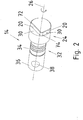
- eine dreidimensionale Ansicht eines Schaltnockens für eine erfindungsgemäße Kupplung;
- Fig. 3:
- eine weitere dreidimensionale Ansicht des in
Figur 2 gezeigten Schaltnockens; - Fig. 4:
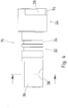
- eine Seitenansicht des in
Figur 2 gezeigten Schaltnockens; - Fig. 5:
- einen Schnitt durch den in
Figur 2 gezeigten Schaltnocken; - In der
Figur 1 ist eine erfindungsgemäße Kupplung 12 in einem Getriebe 10 gezeigt. Das Getriebe 10 umfasst ein Gehäuse 48, welches einen Innenraum 50 umschließt. Das Gehäuse 48 weist einen Deckel 58, einen Eintriebsflansch 60 und einen Abtriebsflansch 62 auf. Am Eintriebsflansch 60 ist zum Beispiel ein nicht gezeigter Elektromotor anflanschbar. Am Abtriebsflansch 62 ist beispielsweise eine nicht gezeigte Treibrad-Einheit für eine Elektrohängebahn anbringbar. - Das Getriebe 10 umfasst weiter ein Ritzel welches mit einem Zahnrad 44 des Getriebes 10 kämmt. Das Ritzel und das Zahnrad 44 sind im Gehäuse 48 angeordnet. Die Welle 42 ist insbesondere als Abtriebswelle ausgeführt. Einen Wellenstumpf 64 der Abtriebswelle ragt durch den Abtriebsflansch 62 aus dem Gehäuse 48 heraus.
- Das Zahnrad 44 ist drehbar auf der Welle 42 des Getriebes 10 angeordnet. Um zwischen einem drehfesten Zustand und einem gegeneinander drehbaren Zustand der Welle 42 relativ zum Zahnrad 44 zu schalten, weist das Getriebe 10 die Kupplung 12 auf.
- Dazu weist die Kupplung 12 einen Schaltnocken 14, ein Schaltelement 16 und ein Federelement 18 auf.
- Das Schaltelement 16 ist drehfest, aber axial verschiebbar auf der Welle 42 angeordnet. Das Schaltelement 16 ist vorzugsweise als Rohrabschnitt 68 ausgeführt, welches die Welle 42 umgibt. Zur drehfesten Verbindung mit der Welle 42 weist der Rohrabschnitt 68 zum Beispiel eine Innenverzahnung auf, welche in eine Verzahnung auf der Welle 42 eingreift, so dass dadurch das Schaltelement 16 auf der Welle 42 axial verschiebbar ist. Die Innenverzahnung und die Verzahnung sind so ausgeführt, dass diese in jeder möglichen axialen Stellung des Schaltelementes 16 zumindest teilweise in Eingriff bleiben. Dazu verlaufen die Zahnkämme der Verzahnung und der Innenverzahnung in axialer Richtung.
- An seinem zum Abtriebsflansch 62 hingerichteten Endstück weist der Rohrabschnitt 68 einen flanschartigen Kragen 66 auf, welcher einstückig mit dem Rohrabschnitt 68 ausgeführt ist. Der Flanschartige Kragen bildet eine zum Zahnrad 44 hingerichtete Fläche 22 und steht vorzugsweise senkrecht zur Achse der Welle 42. Die Fläche 22 weist bei dem in
Figur 1 gezeigten Ausführungsbeispiel die Form eines Rings auf. - Die zum Zahnrad 44 gerichtete Stirnseite des Rohrabschnitts 68 weist Klauen 52 auf. An der zum Schaltelement 16 gerichteten Stirnfläche 56 des Zahnrads 44 sind korrespondierende Klauen 54 ausgeformt. Durch axiales hin- und herschieben des Schaltelementes 16 schaltet die Kupplung 12 zwischen einer eingekuppelten Schaltposition, bei welcher die Klauen 52 in die korrespondierenden Klauen 54 eingreifen und einer ausgekuppelten Position , bei welcher die Klauen 52 und die korrespondierenden Klauen 54 voneinander beabstandet sind. Somit ist das Schaltelement 16 mit dem Zahnrad 44 des Getriebes 10, vorzugsweise formschlüssig, drehfest verbindbar und wieder lösbar ist.
- Der Schaltnocken 14 weist vorteilhafterweise eine zylindrische Grundform auf. Die Bewegung des Schaltelementes 16 in axialer Richtung wird durch Drehen des Schaltnockens 14 um eine Drehachse 26 des Schaltnockens 14 bewirkt. Dazu ist der Schaltnocken 14 mit einem Durchführungsbereich 32 drehbar in einer Gehäusewand 46 des Gehäuses 48 gehalten.
- Der Durchführungsbereich 32 weist insbesondere eine Nut 34 auf, welche radial umläuft und in welcher ein Abdichtungselement, wie zum Beispiel ein O-Ring, gehalten ist. Dadurch ist die Durchführung in der Gehäusewand 46, in welcher der Durchführungsbereich 32 gehalten ist abgedichtet. Bei der in
Figur 1 gezeigten Ausführungsform ist die Durchführung durch eine zylindrische Ausstülpung der Gehäusewand 46 nach außen verlängert ausgeführt. Dadurch ist der Schaltnocken 14 sicherer in der Gehäusewand 46 gehalten. - In axialer Richtung der Drehachse 26 ist der Schaltnocken 14 in der Gehäusewand 46 fixiert. Dies ist zum Beispiel bei der in
Figur 1 gezeigten Ausführungsform dadurch realisiert, dass der Endbereich 24 dicker ausgeführt ist als der Durchführungsbereich 32, insbesondere dicker als die Durchführung. Außerhalb des Gehäuses 48 ist am Schaltnocken 14 ein Sicherungselement, vorzugsweise ein Sicherungsring 70, angeordnet. Es sind aber auch andere Sicherungselemente, wie beispielsweise Splinte, Sicherungsscheiben oder Keile denkbar. - Das Federelement 18 drückt mit einer Federkraft auf das Schaltelement 16 in Richtung zum Zahnrad 44, also hin zur eingekuppelten Schaltposition. Dazu ist das Federelement 18 vorzugsweise als Spiraldruckfeder zwischen dem Schaltelement 16 und einem Abtriebslager, welches die Welle 42 drehbar im Gehäuse 48 lagert, angeordnet. Die Spiraldruckfeder umschließt die Welle 42 und stützt sich vorteilhafterweise auf einem Außenring des Abtriebslagers ab.
- Der Schaltnocken 14 weist zwei Schaltflächen 20 auf. Die Schaltflächen 20 wirken derart mit dem Schaltelement 16 zusammen, dass die auf das Schaltelement 16 wirkende Federkraft in Abhängigkeit vom Drehwinkel des Drehens des Schaltnockens 14 in jeder Schaltposition ein lokales Minimum annimmt.
- Dazu sind zum Beispiel die beiden Schaltflächen 20 an dem Endbereich 24 des Schaltnockens 14 ausgeformt. Der Endbereich 24 schließt sich an den Durchführungsbereich 32 an und liegt innerhalb des Gehäuses 48. Zur Ausbildung der Schaltflächen 20 sind in einem Abschnitt 28 des ansonsten zylinderförmigen Endbereichs 24 zwei Scheibensegmente 30 ausgenommen. Diese scheibensegmentartigen Ausnehmungen schließen sich direkt an die Stirnseite des Schaltnockens 14 an. Die Scheibensegmente 30 weisen unterschiedliche Segmenthöhen auf und sind so angeordnet, dass die, vorteilhafterweise abgefaste, Stirnkante 72 des Endbereiches 24 zwischen den Scheibensegmenten 30 an jeweils mindestens einer Stelle dem eigentlichen Kreisumfang des zylinderförmigen Endbereiches 24 entspricht.
- Bei der in den
Figuren 2 bis 5 gezeigten Ausführungsform des Schaltnockens 14 liegen die Schaltflächen 20 als Ebenen parallel zur Drehachse 26. Die Schaltflächen 20 bilden einen rechten Winkel zueinander. Die Stoßkante 74, an welcher die zwei Schaltflächen 20 aneinander stoßen, ist vorteilhafterweise abgerundet ausgeführt. - Der Schaltnocken 14 ragt so weit in das Gehäuse 48 hinein und ist relativ zum Schaltelement 16 derart angeordnet, dass sich ein Umfangsflächenabschnitt des Endbereiches 24, welcher die Schaltflächen 20 umfasst, mit einem Teilbereich der Fläche 22 überlappt. Vorzugsweise steht die Drehachse 26 senkrecht zur Achse der Welle 42, beziehungsweise zur Bewegungsrichtung des Schaltelementes 16.
- Im eingekuppelten Zustand liegt die Schaltfläche der zwei Schaltflächen 20, welche durch das Scheibensegment der zwei Scheibensegmente 30 mit der größeren Segmenthöhe gebildet ist, der Fläche 22 des Schaltelementes 18 im Wesentlichen planparallel gegenüber. Zwischen dieser Schaltfläche und der Fläche 22 ist insbesondere in der eingekuppelten Schaltposition Spiel vorhanden, so dass zum einen die Fläche 22 nur bei leichter Verdrehung des Schaltnockens 14 unerheblich am Schaltnocken 14 reibt und zum anderen die Federkraft voll über das Schaltelement 16 auf das Zahnrad 44 geleitet ist. Dazu greifen die Klauen 52 und die korrespondierenden Klauen 54 sicher ineinander.
- Das Klauenprofil der Klauen 52 und der korrespondierenden Klauen 54 sind so ausgeführt, dass sie selbsthemmend gegen eine Verdrehung wirken. Andererseits können bei anderen Ausführungsbeispielen das Klauenprofil und die Federkraft so gewählt werde, dass ab einem bestimmten übertragenen Drehmoment die Kupplung 12 durchrutscht.
- Beim Drehen des Schaltnockens 14 tritt nun zwangsläufig ein Teilabschnitt des Umfangsflächenabschnitts in Kontakt mit der Fläche 22 und der Schaltnocken 14 drückt das Schaltelemente 16 beim Weiterdrehen aus der eingekuppelten Schaltposition gegen die Federkraft in eine Position in welcher die Klauen 52 und die korrespondierenden Klauen 54 nicht mehr in Eingriff stehen. Somit besteht keine drehfeste Verbindung zwischen dem Zahnrad 44 und der Welle 42 mehr. Beim Weiterdrehen wird eine Position des Schaltelementes 16 erreicht, in welcher die Federkraft in Bezug auf die Bewegung des Schaltelementes 16 maximal ist.
- Nach dieser Position mit maximaler Kraft drückt die Feder das Schaltelement 16 wieder in Richtung des Zahnrades 44, bis die Fläche 22 gegen die andere der zwei Schaltflächen 20 drückt. Nun hat das Schaltelement 16 die ausgekuppelte Schaltposition erreicht. Die Federkraft wird über das Schaltelement 16 und den Schaltnocken 14 vom Gehäuse 48 aufgenommen. Wird nun die Welle 42 gedreht, so reibt die Fläche 22 auf derjenigen Schaltfläche der zwei Schaltflächen 20, welche durch das Scheibensegment der Scheibensegmente 30 mit der geringeren Segmenthöhe gebildet ist.
- Somit ist das Schaltelement 16 durch Drehen des Schaltnockens 14 um die Drehachse 26 des Schaltnockens 14 zwischen mindestens zwei Schaltpositionen gegen oder mit der auf das Schaltelement 16 wirkenden Federkraft des Federelementes 18 hin und her bewegbar.
- Ausgehend von der eingekuppelten Schaltposition entsteht bei einer vollständigen Umdrehung des Schaltnockens 14 folgender Kraftverlauf. Zuerst ist die Spiraldruckfeder innerhalb der zugelassenen Bewegung am weitesten ausgelenkt und somit die Federkraft minimal. Beim Drehen des Schaltnockens 14 wird das Schaltelement 16 vom Zahnrad 44 weggedrückt und die Schraubendruckfeder gestaucht.
- Die Federkraft steigt bis der mit der Fläche 22 in Kontakt stehende Bereich des Umfangsflächenabschnitts einer ersten maximalen radialen Erstreckung des Schaltnockens 14 beziehungsweise des Umfangsflächenabschnitts entspricht.
- Danach nimmt die Federkraft wieder ab bis die Fläche 22 gegen die Schaltfläche, welcher der ausgekuppelten Schaltposition entspricht, gedrückt wird. Beim Weiterdrehen drückt der Schaltnocken 14 das Schaltelement 16 wieder weg vom Zahnrad 44. Dadurch nimmt die Federkraft wieder zu bis eine zweite maximale radiale Erstreckung des Schaltnockens 14 beziehungsweise des Umfangsflächenabschnitts erreicht wird. Bei einem Zylinderförmigen Endbereich 24 ist die erste maximale radiale Erstreckung insbesondere gleich der zweiten maximalen radialen Erstreckung. Durch diese Ausführungsart liegt die ausgekuppelte Schaltposition in Abhängigkeit des Drehwinkels in einem lokalen Minimum der Federkraft.
- Die Kupplung 12 ist auf zwei verschiedene Arten schaltbar. Entweder durch vollständiges Drehen des Schaltnockens 14 um 360 Grad oder durch hin und her drehen zwischen den beiden durch die Schaltflächen 20 bestimmten Schaltpositionen bestimmten Drehpositionen des Schaltnockens 14 schaltbar. Letztere Möglichkeit unterteilt sich noch in die zwei möglichen Richtungen der Drehung.
- Die lokalen Minima sind vorzugsweise echte lokale Minima, d.h. die Funktionswerte in der Umgebung der Minima sind größer und nicht gleich dem Wert der lokalen Minima.
- Zur leichteren Betätigung des Schaltnockens 14 ist ein dem Endbereich 24 gegenüberliegende Endabschnitt 36 des Schaltnockens 14 eine Befestigungseinrichtung 38 für einen Schalthebel 40 ausgeformt. Vorzugsweise ist die Befestigungseinrichtung 38 als eine durchgehende Ausnehmung im Endabschnitt 36 ausgeführt. Die durchgehende Ausnehmung weist ein Innengewinde auf. In das Innengewinde ist ein passendes Außengewinde des Schalthebels 40 einschraubbar.
- Vorzugsweise ist an dem Außengewinde des Schalthebels 40 eine Kontermutter vorgesehen, welche gegen einen abgeplatteten Bereich des im Wesentlichen zylinderförmigen Endabschnitts 36 drückt. Dadurch wird ein selbstständiges herausdrehen des Schalthebels 40 aus dem Innengewinde verhindert.
- Um ein selbsttätiges Schalten der Kupplung 12 zu verhindern, ist der Schalthebel 40 derart ausgeführt, dass eine Kraftkomponente der Gewichtskraft des Schalthebels 40, welche über den Schaltnocken 14 auf das Schaltelement 16 wirkt, kleiner als die Federkraft ist. Insbesondere ist diese Bedingung bei jeder Lage beziehungsweise Einbaulage des Getriebes 10 erfüllt. Dies hat den weiteren Vorteil, dass ein Anschlag für den Schalthebel 40 unnötig ist. Die Kupplung 12 lässt sich auch durch ein vollständiges umdrehen des Schalthebels 40 betätigen.
- Vorteilhafterweise ist das Getriebe 10 bei einer Laufkatze für eine Elektrohängebahn eingesetzt. Das Getriebe 10 ist dafür mit einem Motor der Laufkatze verbunden. Die Abtriebswelle des Getriebes 10 wird von dem Motor angetrieben. Ein Laufrad der Laufkatze ist mit der Abtriebswelle des Getriebes 10 drehfest verbunden. Bei einem Störfall ist es wichtig, dass die Förderelemente der Elektrohängebahn frei beweglich sind. Dazu lässt sich per Hand die drehfeste Verbindung der Abtriebswelle und dem Motor mit der Kupplung 12 trennen. So wird verhindert, dass sich das Förderelement von alleine bewegt, aber trotzdem gezielt bewegbar ist. Somit ist die Sicherheit der Elektrohängebahn erhöht.
-
- 10
- Getriebe
- 12
- Kupplung
- 14
- Schaltnocken
- 16
- Schaltelement
- 18
- Federelement
- 20
- Schaltflächen
- 22
- Fläche
- 24
- Endbereich
- 26
- Drehachse
- 28
- Abschnitt
- 30
- Scheibensegment
- 32
- Durchführungsbereich
- 34
- Nut
- 36
- Endabschnitt
- 38
- Befestigungseinrichtung
- 40
- Schalthebel
- 42
- Welle
- 44
- Zahnrad
- 46
- Gehäusewand
- 48
- Gehäuse
- 50
- Innenraum
- 52
- Klauen
- 54
- korrespondierende Klauen
- 56
- Stirnfläche
- 58
- Deckel
- 60
- Eintriebsflansch
- 62
- Abtriebsflansch
- 64
- Wellenstumpf
- 66
- flanschartiger Kragen
- 68
- Rohrabschnitt
- 70
- Sicherungsring
- 72
- Stirnkante
- 74
- Stoßkante
Claims (10)
- Getriebe mit Kupplung,
wobei die Kupplung einen Schaltnocken (14), ein Schaltelement (16) und ein Federelement (18) aufweist,
wobei das Schaltelement (16) durch Drehen des Schaltnockens (14) um die Drehachse des Schaltnockens (14) zwischen mindestens zwei Schaltpositionen gegen oder mit einer auf das Schaltelement (16) wirkenden Federkraft des Federelementes (18) hin und her bewegbar ist,
wobei der Schaltnocken (14) zwei Schaltflächen aufweist, und
die Schaltflächen mit dem Schaltelement (16) derart zusammenwirken, dass die auf das Schaltelement (16) wirkende Federkraft in Abhängigkeit vom Drehwinkel des Drehens in jeder Schaltposition ein lokales Minimum annimmt,
wobei das Schaltelement (16) mit einem Zahnrad (44) des Getriebes, vorzugsweise formschlüssig, drehfest verbindbar und wieder lösbar ist,
der Schaltnocken (14), insbesondere mit seinem Durchführungsabschnitt, in einer Gehäusewand eines Gehäuses des Getriebes gehalten ist,
wobei die Schaltflächen und das Schaltelement (16) in einem Innenraum des Gehäuses angeordnet sind,
wobei das Schaltelement (16) auf einer Welle, insbesondere Abtriebswelle, des Getriebes drehfest und axial verschiebbar angeordnet ist,
wobei die Federkraft das Schaltelement (16) in Richtung eines Zahnrades, welches drehbar auf der Welle (42)angeordnet ist, drückt, wobei das Schaltelement (16) im eingekuppelten Zustand drehfest mit dem Zahnrad verbunden ist, insbesondere Klauen (52) des Mitnehmers und dazu korrespondierende Klauen (54) in einer Stirnfläche des Zahnrades gegenseitig ineinandergreifen,
wobei am Schaltnocken (14) außerhalb der Getriebegehäuses ein Schalthebel angeordnet ist, mit welchem der Schaltnocken (14) gedreht wird, insbesondere wobei ein Kraftkomponente vom Schaltnocken (14) auf das Schaltelement (16), welche durch die Gewichtskraft des Schalthebels hervorgerufen ist, in jeder Lage des Getriebes kleiner ist als die Federkraft auf das Schaltelement (16),
dadurch gekennzeichnet, dass
die Schaltflächen eben sind und parallel zur Drehachse angeordnet sind,- wobei die Schaltflächen zueinander in einem Winkel angeordnet sind, vorzugsweise im Wesentlichen senkrecht zueinander angeordnet sind,- und/oder wobei ein Endbereich einen Abschnitt aufweist, aus welchem zwei Scheibensegmente zur Bildung der Schaltflächen an einem freien Ende des Endbereiches ausgenommen sind. - Getriebe nach Anspruch 1,
dadurch gekennzeichnet, dass
der Schaltnocken (14) mit dem Schaltelement (16) derart zusammenwirkt, dass beim Drehen des Schaltnockens (14) auf das Schaltelement (16) zwischen den mindestens zwei Schaltpositionen bei mindestens einer Drehposition des Schaltnockens (14) eine maximale Federkraft wirkt. - Getriebe nach Anspruch 1 oder 2,
dadurch gekennzeichnet, dass
die zwei Schaltflächen zu einer Fläche des Schaltelements korrespondieren, wobei in einem der mindestens zwei Schaltzustände die entsprechende Schaltfläche gegen die Fläche drückt. - Getriebe nach Anspruch 1, 2 oder 3,
dadurch gekennzeichnet, dass
in einem zweiten der mindestens zwei Schaltzustände die zugehörige Schaltfläche parallel bis annähernd parallel von der Fläche beabstandet ist,
und/oder
die zwei Schaltflächen an dem Endbereich des Schaltnockens (14) angeordnet sind. - Getriebe nach einem der vorrangegangenen Ansprüche,
dadurch gekennzeichnet, dass
der Schaltnocken (14) zylinderförmig ist. - Getriebe nach einem der vorrangegangenen Ansprüche,
dadurch gekennzeichnet, dass
sich an den Endbereich ein Durchführungsbereich des Schaltnockens (14) anschließt, welcher eine zur Drehachse radial umlaufende Nut zur Aufnahme eines Dichtungselementes, insbesondere eines O-Ringes, aufweist,
und/oder
der dem Endbereich gegenüberliegende Endabschnitt das Schaltnockens (14) eine Befestigungseinrichtung für einen Betätigungshebel aufweist. - Getriebe nach einem der vorrangegangenen Ansprüche,
dadurch gekennzeichnet, dass
das Schaltelement (16) durch das Drehen des Schaltnockens (14) in einer Richtung senkrecht zur Drehachse des Schaltnockens (14) zwischen einer Einkuppelposition und einer Auskuppelposition hin und her bewegbar ist. - Getriebe nach einem der vorrangegangenen Ansprüche,
dadurch gekennzeichnet, dass
das Schaltelement (16) drehfest und axial verschiebbar mit einer Welle (42) des Getriebes verbindbar ist. - Laufkatze für eine Elektrohängebahn mit einem Getriebe nach einem der Ansprüche 1 bis 8, wobei das Getriebe von einem Motor der Laufkatze angetrieben ist und ein Laufrad der Laufkatze mit der Welle des Getriebes drehfest verbunden ist.
- Elektrohängebahn mit einer Laufkatze nach Anspruch 9.
Applications Claiming Priority (2)
| Application Number | Priority Date | Filing Date | Title |
|---|---|---|---|
| DE201010014582 DE102010014582B4 (de) | 2010-04-09 | 2010-04-09 | Kupplung für ein Getriebe |
| PCT/EP2011/001371 WO2011124324A1 (de) | 2010-04-09 | 2011-03-21 | Kupplung für ein getriebe |
Publications (2)
| Publication Number | Publication Date |
|---|---|
| EP2556265A1 EP2556265A1 (de) | 2013-02-13 |
| EP2556265B1 true EP2556265B1 (de) | 2018-12-19 |
Family
ID=44065342
Family Applications (1)
| Application Number | Title | Priority Date | Filing Date |
|---|---|---|---|
| EP11710701.1A Active EP2556265B1 (de) | 2010-04-09 | 2011-03-21 | Getriebe mit kupplung |
Country Status (3)
| Country | Link |
|---|---|
| EP (1) | EP2556265B1 (de) |
| DE (1) | DE102010014582B4 (de) |
| WO (1) | WO2011124324A1 (de) |
Families Citing this family (2)
| Publication number | Priority date | Publication date | Assignee | Title |
|---|---|---|---|---|
| DE102011103104B4 (de) * | 2011-05-25 | 2019-03-28 | Sew-Eurodrive Gmbh & Co Kg | Kupplung für ein Getriebe, Getriebe mit einer Kupplung, Laufkatze für eine Elektrohängebahn mit einem Getriebe |
| EP3096037A1 (de) * | 2015-05-22 | 2016-11-23 | Goodrich Actuation Systems SAS | Stellantriebs-trennungssystem |
Family Cites Families (7)
| Publication number | Priority date | Publication date | Assignee | Title |
|---|---|---|---|---|
| DE1497261A1 (de) * | 1966-12-31 | 1969-04-03 | Standard Elek K Lorenz Ag | Ausrueckbare,axial wirkende Zahnkupplung fuer feinwerktechnische Geraete |
| US4789366A (en) * | 1987-06-24 | 1988-12-06 | Outboard Marine Corporation | Marine propulsion device ball clutch transmission |
| US4945780A (en) * | 1989-04-10 | 1990-08-07 | Bosma Machine And Tool Corporation | Drive unit for a monorail carrier |
| JP3414484B2 (ja) * | 1994-04-14 | 2003-06-09 | 株式会社ダイフク | 電車利用の搬送装置 |
| JP2001097281A (ja) * | 1999-09-30 | 2001-04-10 | Suzuki Motor Corp | 船外機のシフト構造 |
| US6817461B1 (en) * | 2003-03-24 | 2004-11-16 | Brunswick Corporation | Clutch mechanism with overtravel capability |
| JP2007120684A (ja) * | 2005-10-31 | 2007-05-17 | Yamaha Motor Co Ltd | クラッチおよびそれを備えた車両 |
-
2010
- 2010-04-09 DE DE201010014582 patent/DE102010014582B4/de active Active
-
2011
- 2011-03-21 WO PCT/EP2011/001371 patent/WO2011124324A1/de not_active Ceased
- 2011-03-21 EP EP11710701.1A patent/EP2556265B1/de active Active
Non-Patent Citations (1)
| Title |
|---|
| None * |
Also Published As
| Publication number | Publication date |
|---|---|
| WO2011124324A1 (de) | 2011-10-13 |
| DE102010014582A1 (de) | 2011-12-15 |
| DE102010014582B4 (de) | 2012-04-12 |
| EP2556265A1 (de) | 2013-02-13 |
Similar Documents
| Publication | Publication Date | Title |
|---|---|---|
| EP3516249B1 (de) | Mehrfachkupplungseinrichtung und hybridmodul für ein kraftfahrzeug | |
| EP2708768B1 (de) | Antriebseinheit für ein kraftfahrzeug mit einer elektrischen maschine und einer kupplung | |
| EP2145118B1 (de) | Drehmomenten-/drehzahldifferenzabhängige kupplungsbetätigungseinheit für motorangetriebene fahrzeuge | |
| EP3094840B1 (de) | Drehschieberanordnung mit einer verstellanordnung | |
| EP3478992A1 (de) | Parksperreneinheit und elektroantriebsanordnung mit einer parksperre | |
| DE102015220920B4 (de) | Baugruppe mit einer Reibeinrichtung | |
| DE102014209939A1 (de) | Getriebeanordnung mit Sperrfunktion | |
| EP1388682B1 (de) | Drehmomentübertragungsvorrichtung in einem Kraftfahrzeug | |
| DE102015217164A1 (de) | Baugruppe mit einer Reibeinrichtung | |
| WO2019015711A1 (de) | Hybridmodul | |
| DE112018006711T5 (de) | Bremsvorrichtung | |
| EP2228157A1 (de) | Elektromotorisch angetriebenes Schraub- oder Bohrwerkzeug | |
| EP2715173B1 (de) | Kupplung für ein getriebe | |
| DE102010014582B4 (de) | Kupplung für ein Getriebe | |
| DE10155146B4 (de) | Vorrichtung zur automatischen Verschleißnachstellung in einer Reibungskupplung, insbesondere für Kraftfahrzeuge | |
| DE102015220680A1 (de) | Baugruppe mit einer Reibeinrichtung | |
| DE102015100906A1 (de) | Synchronisiereinrichtung, Kupplungsanordnung und Antriebsanordnung | |
| DE102011086985A1 (de) | Selbstnachstellende Kupplung | |
| WO2019101565A1 (de) | Einheit, bestehend aus einem getriebe und einer bremse, und elektromotorisch angetriebenes fahrzeug mit einer solchen einheit | |
| DE102019206659B3 (de) | Parksperrenanordnung mit redundanter Betätigungsvorrichtung und Verfahren einer solchen | |
| WO2018060221A1 (de) | Stellantrieb mit einem zweiteiligen doppelzahnrad mit freilauf zum mechanischen schutz des getriebes und gehäuses des stellantriebs | |
| WO2016128010A1 (de) | Bremsanordnung mit einem bremsbelagträger und einem mitnehmer | |
| DE102014218359B3 (de) | Reibungskupplung mit einer Verschleißnachstelleinrichtung | |
| DE102015207082B4 (de) | Aktor mit einer Reibeinrichtung unter Verwendung eines Schlingfederelementes | |
| DE102015206786A1 (de) | Aktorsystem |
Legal Events
| Date | Code | Title | Description |
|---|---|---|---|
| PUAI | Public reference made under article 153(3) epc to a published international application that has entered the european phase |
Free format text: ORIGINAL CODE: 0009012 |
|
| 17P | Request for examination filed |
Effective date: 20121109 |
|
| AK | Designated contracting states |
Kind code of ref document: A1 Designated state(s): AL AT BE BG CH CY CZ DE DK EE ES FI FR GB GR HR HU IE IS IT LI LT LU LV MC MK MT NL NO PL PT RO RS SE SI SK SM TR |
|
| DAX | Request for extension of the european patent (deleted) | ||
| STAA | Information on the status of an ep patent application or granted ep patent |
Free format text: STATUS: EXAMINATION IS IN PROGRESS |
|
| 17Q | First examination report despatched |
Effective date: 20170403 |
|
| GRAP | Despatch of communication of intention to grant a patent |
Free format text: ORIGINAL CODE: EPIDOSNIGR1 |
|
| STAA | Information on the status of an ep patent application or granted ep patent |
Free format text: STATUS: GRANT OF PATENT IS INTENDED |
|
| INTG | Intention to grant announced |
Effective date: 20180730 |
|
| GRAS | Grant fee paid |
Free format text: ORIGINAL CODE: EPIDOSNIGR3 |
|
| GRAA | (expected) grant |
Free format text: ORIGINAL CODE: 0009210 |
|
| STAA | Information on the status of an ep patent application or granted ep patent |
Free format text: STATUS: THE PATENT HAS BEEN GRANTED |
|
| AK | Designated contracting states |
Kind code of ref document: B1 Designated state(s): AL AT BE BG CH CY CZ DE DK EE ES FI FR GB GR HR HU IE IS IT LI LT LU LV MC MK MT NL NO PL PT RO RS SE SI SK SM TR |
|
| REG | Reference to a national code |
Ref country code: GB Ref legal event code: FG4D Free format text: NOT ENGLISH |
|
| REG | Reference to a national code |
Ref country code: CH Ref legal event code: EP Ref country code: CH Ref legal event code: NV Representative=s name: HEPP WENGER RYFFEL AG, CH |
|
| REG | Reference to a national code |
Ref country code: DE Ref legal event code: R096 Ref document number: 502011015175 Country of ref document: DE |
|
| REG | Reference to a national code |
Ref country code: IE Ref legal event code: FG4D Free format text: LANGUAGE OF EP DOCUMENT: GERMAN |
|
| REG | Reference to a national code |
Ref country code: AT Ref legal event code: REF Ref document number: 1079061 Country of ref document: AT Kind code of ref document: T Effective date: 20190115 |
|
| REG | Reference to a national code |
Ref country code: NL Ref legal event code: FP |
|
| PG25 | Lapsed in a contracting state [announced via postgrant information from national office to epo] |
Ref country code: LV Free format text: LAPSE BECAUSE OF FAILURE TO SUBMIT A TRANSLATION OF THE DESCRIPTION OR TO PAY THE FEE WITHIN THE PRESCRIBED TIME-LIMIT Effective date: 20181219 Ref country code: HR Free format text: LAPSE BECAUSE OF FAILURE TO SUBMIT A TRANSLATION OF THE DESCRIPTION OR TO PAY THE FEE WITHIN THE PRESCRIBED TIME-LIMIT Effective date: 20181219 Ref country code: NO Free format text: LAPSE BECAUSE OF FAILURE TO SUBMIT A TRANSLATION OF THE DESCRIPTION OR TO PAY THE FEE WITHIN THE PRESCRIBED TIME-LIMIT Effective date: 20190319 Ref country code: BG Free format text: LAPSE BECAUSE OF FAILURE TO SUBMIT A TRANSLATION OF THE DESCRIPTION OR TO PAY THE FEE WITHIN THE PRESCRIBED TIME-LIMIT Effective date: 20190319 Ref country code: LT Free format text: LAPSE BECAUSE OF FAILURE TO SUBMIT A TRANSLATION OF THE DESCRIPTION OR TO PAY THE FEE WITHIN THE PRESCRIBED TIME-LIMIT Effective date: 20181219 Ref country code: FI Free format text: LAPSE BECAUSE OF FAILURE TO SUBMIT A TRANSLATION OF THE DESCRIPTION OR TO PAY THE FEE WITHIN THE PRESCRIBED TIME-LIMIT Effective date: 20181219 |
|
| REG | Reference to a national code |
Ref country code: LT Ref legal event code: MG4D |
|
| PG25 | Lapsed in a contracting state [announced via postgrant information from national office to epo] |
Ref country code: SE Free format text: LAPSE BECAUSE OF FAILURE TO SUBMIT A TRANSLATION OF THE DESCRIPTION OR TO PAY THE FEE WITHIN THE PRESCRIBED TIME-LIMIT Effective date: 20181219 Ref country code: RS Free format text: LAPSE BECAUSE OF FAILURE TO SUBMIT A TRANSLATION OF THE DESCRIPTION OR TO PAY THE FEE WITHIN THE PRESCRIBED TIME-LIMIT Effective date: 20181219 Ref country code: AL Free format text: LAPSE BECAUSE OF FAILURE TO SUBMIT A TRANSLATION OF THE DESCRIPTION OR TO PAY THE FEE WITHIN THE PRESCRIBED TIME-LIMIT Effective date: 20181219 Ref country code: GR Free format text: LAPSE BECAUSE OF FAILURE TO SUBMIT A TRANSLATION OF THE DESCRIPTION OR TO PAY THE FEE WITHIN THE PRESCRIBED TIME-LIMIT Effective date: 20190320 |
|
| PG25 | Lapsed in a contracting state [announced via postgrant information from national office to epo] |
Ref country code: PL Free format text: LAPSE BECAUSE OF FAILURE TO SUBMIT A TRANSLATION OF THE DESCRIPTION OR TO PAY THE FEE WITHIN THE PRESCRIBED TIME-LIMIT Effective date: 20181219 Ref country code: PT Free format text: LAPSE BECAUSE OF FAILURE TO SUBMIT A TRANSLATION OF THE DESCRIPTION OR TO PAY THE FEE WITHIN THE PRESCRIBED TIME-LIMIT Effective date: 20190419 Ref country code: ES Free format text: LAPSE BECAUSE OF FAILURE TO SUBMIT A TRANSLATION OF THE DESCRIPTION OR TO PAY THE FEE WITHIN THE PRESCRIBED TIME-LIMIT Effective date: 20181219 Ref country code: CZ Free format text: LAPSE BECAUSE OF FAILURE TO SUBMIT A TRANSLATION OF THE DESCRIPTION OR TO PAY THE FEE WITHIN THE PRESCRIBED TIME-LIMIT Effective date: 20181219 |
|
| PG25 | Lapsed in a contracting state [announced via postgrant information from national office to epo] |
Ref country code: RO Free format text: LAPSE BECAUSE OF FAILURE TO SUBMIT A TRANSLATION OF THE DESCRIPTION OR TO PAY THE FEE WITHIN THE PRESCRIBED TIME-LIMIT Effective date: 20181219 Ref country code: SK Free format text: LAPSE BECAUSE OF FAILURE TO SUBMIT A TRANSLATION OF THE DESCRIPTION OR TO PAY THE FEE WITHIN THE PRESCRIBED TIME-LIMIT Effective date: 20181219 Ref country code: IS Free format text: LAPSE BECAUSE OF FAILURE TO SUBMIT A TRANSLATION OF THE DESCRIPTION OR TO PAY THE FEE WITHIN THE PRESCRIBED TIME-LIMIT Effective date: 20190419 Ref country code: EE Free format text: LAPSE BECAUSE OF FAILURE TO SUBMIT A TRANSLATION OF THE DESCRIPTION OR TO PAY THE FEE WITHIN THE PRESCRIBED TIME-LIMIT Effective date: 20181219 Ref country code: SM Free format text: LAPSE BECAUSE OF FAILURE TO SUBMIT A TRANSLATION OF THE DESCRIPTION OR TO PAY THE FEE WITHIN THE PRESCRIBED TIME-LIMIT Effective date: 20181219 |
|
| REG | Reference to a national code |
Ref country code: DE Ref legal event code: R097 Ref document number: 502011015175 Country of ref document: DE |
|
| PLBE | No opposition filed within time limit |
Free format text: ORIGINAL CODE: 0009261 |
|
| STAA | Information on the status of an ep patent application or granted ep patent |
Free format text: STATUS: NO OPPOSITION FILED WITHIN TIME LIMIT |
|
| PG25 | Lapsed in a contracting state [announced via postgrant information from national office to epo] |
Ref country code: DK Free format text: LAPSE BECAUSE OF FAILURE TO SUBMIT A TRANSLATION OF THE DESCRIPTION OR TO PAY THE FEE WITHIN THE PRESCRIBED TIME-LIMIT Effective date: 20181219 Ref country code: MC Free format text: LAPSE BECAUSE OF FAILURE TO SUBMIT A TRANSLATION OF THE DESCRIPTION OR TO PAY THE FEE WITHIN THE PRESCRIBED TIME-LIMIT Effective date: 20181219 |
|
| 26N | No opposition filed |
Effective date: 20190920 |
|
| PG25 | Lapsed in a contracting state [announced via postgrant information from national office to epo] |
Ref country code: LU Free format text: LAPSE BECAUSE OF NON-PAYMENT OF DUE FEES Effective date: 20190321 |
|
| REG | Reference to a national code |
Ref country code: BE Ref legal event code: MM Effective date: 20190331 |
|
| PG25 | Lapsed in a contracting state [announced via postgrant information from national office to epo] |
Ref country code: IE Free format text: LAPSE BECAUSE OF NON-PAYMENT OF DUE FEES Effective date: 20190321 |
|
| PG25 | Lapsed in a contracting state [announced via postgrant information from national office to epo] |
Ref country code: SI Free format text: LAPSE BECAUSE OF FAILURE TO SUBMIT A TRANSLATION OF THE DESCRIPTION OR TO PAY THE FEE WITHIN THE PRESCRIBED TIME-LIMIT Effective date: 20181219 Ref country code: BE Free format text: LAPSE BECAUSE OF NON-PAYMENT OF DUE FEES Effective date: 20190331 |
|
| PG25 | Lapsed in a contracting state [announced via postgrant information from national office to epo] |
Ref country code: TR Free format text: LAPSE BECAUSE OF FAILURE TO SUBMIT A TRANSLATION OF THE DESCRIPTION OR TO PAY THE FEE WITHIN THE PRESCRIBED TIME-LIMIT Effective date: 20181219 |
|
| PG25 | Lapsed in a contracting state [announced via postgrant information from national office to epo] |
Ref country code: MT Free format text: LAPSE BECAUSE OF FAILURE TO SUBMIT A TRANSLATION OF THE DESCRIPTION OR TO PAY THE FEE WITHIN THE PRESCRIBED TIME-LIMIT Effective date: 20181219 |
|
| PG25 | Lapsed in a contracting state [announced via postgrant information from national office to epo] |
Ref country code: CY Free format text: LAPSE BECAUSE OF FAILURE TO SUBMIT A TRANSLATION OF THE DESCRIPTION OR TO PAY THE FEE WITHIN THE PRESCRIBED TIME-LIMIT Effective date: 20181219 |
|
| PG25 | Lapsed in a contracting state [announced via postgrant information from national office to epo] |
Ref country code: HU Free format text: LAPSE BECAUSE OF FAILURE TO SUBMIT A TRANSLATION OF THE DESCRIPTION OR TO PAY THE FEE WITHIN THE PRESCRIBED TIME-LIMIT; INVALID AB INITIO Effective date: 20110321 |
|
| PG25 | Lapsed in a contracting state [announced via postgrant information from national office to epo] |
Ref country code: MK Free format text: LAPSE BECAUSE OF FAILURE TO SUBMIT A TRANSLATION OF THE DESCRIPTION OR TO PAY THE FEE WITHIN THE PRESCRIBED TIME-LIMIT Effective date: 20181219 |
|
| PGFP | Annual fee paid to national office [announced via postgrant information from national office to epo] |
Ref country code: CH Payment date: 20250401 Year of fee payment: 15 |
|
| PGFP | Annual fee paid to national office [announced via postgrant information from national office to epo] |
Ref country code: NL Payment date: 20260213 Year of fee payment: 16 |
|
| REG | Reference to a national code |
Ref country code: DE Ref legal event code: R084 Ref document number: 502011015175 Country of ref document: DE |
|
| REG | Reference to a national code |
Ref country code: CH Ref legal event code: U11 Free format text: ST27 STATUS EVENT CODE: U-0-0-U10-U11 (AS PROVIDED BY THE NATIONAL OFFICE) Effective date: 20260401 |
|
| PGFP | Annual fee paid to national office [announced via postgrant information from national office to epo] |
Ref country code: GB Payment date: 20260202 Year of fee payment: 16 |
|
| PGFP | Annual fee paid to national office [announced via postgrant information from national office to epo] |
Ref country code: DE Payment date: 20260331 Year of fee payment: 16 |
|
| PGFP | Annual fee paid to national office [announced via postgrant information from national office to epo] |
Ref country code: AT Payment date: 20260310 Year of fee payment: 16 |
|
| PGFP | Annual fee paid to national office [announced via postgrant information from national office to epo] |
Ref country code: IT Payment date: 20260220 Year of fee payment: 16 |
|
| PGFP | Annual fee paid to national office [announced via postgrant information from national office to epo] |
Ref country code: FR Payment date: 20260209 Year of fee payment: 16 |