EP2555710B1 - Transcatheter prosthetic heart valve delivery system with recapturing feature - Google Patents
Transcatheter prosthetic heart valve delivery system with recapturing feature Download PDFInfo
- Publication number
- EP2555710B1 EP2555710B1 EP11712427.1A EP11712427A EP2555710B1 EP 2555710 B1 EP2555710 B1 EP 2555710B1 EP 11712427 A EP11712427 A EP 11712427A EP 2555710 B1 EP2555710 B1 EP 2555710B1
- Authority
- EP
- European Patent Office
- Prior art keywords
- heart valve
- prosthetic heart
- capsule
- actuator
- forces
- Prior art date
- Legal status (The legal status is an assumption and is not a legal conclusion. Google has not performed a legal analysis and makes no representation as to the accuracy of the status listed.)
- Active
Links
- 210000003709 heart valve Anatomy 0.000 title claims description 143
- 239000002775 capsule Substances 0.000 claims description 74
- 230000008878 coupling Effects 0.000 claims description 13
- 238000010168 coupling process Methods 0.000 claims description 13
- 238000005859 coupling reaction Methods 0.000 claims description 13
- 230000000717 retained effect Effects 0.000 claims description 4
- 230000007704 transition Effects 0.000 claims description 4
- 238000000034 method Methods 0.000 description 23
- 238000002513 implantation Methods 0.000 description 19
- 238000010276 construction Methods 0.000 description 14
- 239000000463 material Substances 0.000 description 7
- 210000001765 aortic valve Anatomy 0.000 description 6
- 230000007246 mechanism Effects 0.000 description 6
- 210000002376 aorta thoracic Anatomy 0.000 description 5
- 230000014759 maintenance of location Effects 0.000 description 4
- 229910052751 metal Inorganic materials 0.000 description 4
- 239000002184 metal Substances 0.000 description 4
- 230000000694 effects Effects 0.000 description 3
- 238000011156 evaluation Methods 0.000 description 3
- 230000036961 partial effect Effects 0.000 description 3
- 238000001356 surgical procedure Methods 0.000 description 3
- 241000283690 Bos taurus Species 0.000 description 2
- 241000283073 Equus caballus Species 0.000 description 2
- 239000004696 Poly ether ether ketone Substances 0.000 description 2
- JUPQTSLXMOCDHR-UHFFFAOYSA-N benzene-1,4-diol;bis(4-fluorophenyl)methanone Chemical compound OC1=CC=C(O)C=C1.C1=CC(F)=CC=C1C(=O)C1=CC=C(F)C=C1 JUPQTSLXMOCDHR-UHFFFAOYSA-N 0.000 description 2
- 230000006835 compression Effects 0.000 description 2
- 238000007906 compression Methods 0.000 description 2
- 230000002950 deficient Effects 0.000 description 2
- 210000001105 femoral artery Anatomy 0.000 description 2
- 229920005570 flexible polymer Polymers 0.000 description 2
- 230000006870 function Effects 0.000 description 2
- 208000014674 injury Diseases 0.000 description 2
- 210000004115 mitral valve Anatomy 0.000 description 2
- 229910001000 nickel titanium Inorganic materials 0.000 description 2
- 229920002530 polyetherether ketone Polymers 0.000 description 2
- 229920000642 polymer Polymers 0.000 description 2
- 230000008733 trauma Effects 0.000 description 2
- 210000000591 tricuspid valve Anatomy 0.000 description 2
- 230000002792 vascular Effects 0.000 description 2
- 208000001647 Renal Insufficiency Diseases 0.000 description 1
- 208000006011 Stroke Diseases 0.000 description 1
- 239000000853 adhesive Substances 0.000 description 1
- 230000001070 adhesive effect Effects 0.000 description 1
- 230000002411 adverse Effects 0.000 description 1
- 210000003484 anatomy Anatomy 0.000 description 1
- 210000000709 aorta Anatomy 0.000 description 1
- 230000017531 blood circulation Effects 0.000 description 1
- 238000009954 braiding Methods 0.000 description 1
- 238000002788 crimping Methods 0.000 description 1
- 230000007812 deficiency Effects 0.000 description 1
- 230000001419 dependent effect Effects 0.000 description 1
- 238000005516 engineering process Methods 0.000 description 1
- 238000002695 general anesthesia Methods 0.000 description 1
- 238000003384 imaging method Methods 0.000 description 1
- 230000006872 improvement Effects 0.000 description 1
- 208000015181 infectious disease Diseases 0.000 description 1
- 201000006370 kidney failure Diseases 0.000 description 1
- 230000000670 limiting effect Effects 0.000 description 1
- 239000002861 polymer material Substances 0.000 description 1
- 230000008569 process Effects 0.000 description 1
- 210000003102 pulmonary valve Anatomy 0.000 description 1
- 230000002829 reductive effect Effects 0.000 description 1
- 230000002787 reinforcement Effects 0.000 description 1
- 230000008439 repair process Effects 0.000 description 1
- 230000004044 response Effects 0.000 description 1
- 238000009958 sewing Methods 0.000 description 1
- 239000012781 shape memory material Substances 0.000 description 1
- 239000007787 solid Substances 0.000 description 1
- 210000005166 vasculature Anatomy 0.000 description 1
- 210000003462 vein Anatomy 0.000 description 1
- 210000002073 venous valve Anatomy 0.000 description 1
Images

Classifications
-
- A—HUMAN NECESSITIES
- A61—MEDICAL OR VETERINARY SCIENCE; HYGIENE
- A61F—FILTERS IMPLANTABLE INTO BLOOD VESSELS; PROSTHESES; DEVICES PROVIDING PATENCY TO, OR PREVENTING COLLAPSING OF, TUBULAR STRUCTURES OF THE BODY, e.g. STENTS; ORTHOPAEDIC, NURSING OR CONTRACEPTIVE DEVICES; FOMENTATION; TREATMENT OR PROTECTION OF EYES OR EARS; BANDAGES, DRESSINGS OR ABSORBENT PADS; FIRST-AID KITS
- A61F2/00—Filters implantable into blood vessels; Prostheses, i.e. artificial substitutes or replacements for parts of the body; Appliances for connecting them with the body; Devices providing patency to, or preventing collapsing of, tubular structures of the body, e.g. stents
- A61F2/02—Prostheses implantable into the body
- A61F2/24—Heart valves ; Vascular valves, e.g. venous valves; Heart implants, e.g. passive devices for improving the function of the native valve or the heart muscle; Transmyocardial revascularisation [TMR] devices; Valves implantable in the body
- A61F2/2427—Devices for manipulating or deploying heart valves during implantation
- A61F2/2436—Deployment by retracting a sheath
-
- A—HUMAN NECESSITIES
- A61—MEDICAL OR VETERINARY SCIENCE; HYGIENE
- A61F—FILTERS IMPLANTABLE INTO BLOOD VESSELS; PROSTHESES; DEVICES PROVIDING PATENCY TO, OR PREVENTING COLLAPSING OF, TUBULAR STRUCTURES OF THE BODY, e.g. STENTS; ORTHOPAEDIC, NURSING OR CONTRACEPTIVE DEVICES; FOMENTATION; TREATMENT OR PROTECTION OF EYES OR EARS; BANDAGES, DRESSINGS OR ABSORBENT PADS; FIRST-AID KITS
- A61F2/00—Filters implantable into blood vessels; Prostheses, i.e. artificial substitutes or replacements for parts of the body; Appliances for connecting them with the body; Devices providing patency to, or preventing collapsing of, tubular structures of the body, e.g. stents
- A61F2/02—Prostheses implantable into the body
- A61F2/24—Heart valves ; Vascular valves, e.g. venous valves; Heart implants, e.g. passive devices for improving the function of the native valve or the heart muscle; Transmyocardial revascularisation [TMR] devices; Valves implantable in the body
- A61F2/2412—Heart valves ; Vascular valves, e.g. venous valves; Heart implants, e.g. passive devices for improving the function of the native valve or the heart muscle; Transmyocardial revascularisation [TMR] devices; Valves implantable in the body with soft flexible valve members, e.g. tissue valves shaped like natural valves
- A61F2/2418—Scaffolds therefor, e.g. support stents
-
- A—HUMAN NECESSITIES
- A61—MEDICAL OR VETERINARY SCIENCE; HYGIENE
- A61F—FILTERS IMPLANTABLE INTO BLOOD VESSELS; PROSTHESES; DEVICES PROVIDING PATENCY TO, OR PREVENTING COLLAPSING OF, TUBULAR STRUCTURES OF THE BODY, e.g. STENTS; ORTHOPAEDIC, NURSING OR CONTRACEPTIVE DEVICES; FOMENTATION; TREATMENT OR PROTECTION OF EYES OR EARS; BANDAGES, DRESSINGS OR ABSORBENT PADS; FIRST-AID KITS
- A61F2/00—Filters implantable into blood vessels; Prostheses, i.e. artificial substitutes or replacements for parts of the body; Appliances for connecting them with the body; Devices providing patency to, or preventing collapsing of, tubular structures of the body, e.g. stents
- A61F2/02—Prostheses implantable into the body
- A61F2/24—Heart valves ; Vascular valves, e.g. venous valves; Heart implants, e.g. passive devices for improving the function of the native valve or the heart muscle; Transmyocardial revascularisation [TMR] devices; Valves implantable in the body
- A61F2/2427—Devices for manipulating or deploying heart valves during implantation
- A61F2/243—Deployment by mechanical expansion
-
- A—HUMAN NECESSITIES
- A61—MEDICAL OR VETERINARY SCIENCE; HYGIENE
- A61F—FILTERS IMPLANTABLE INTO BLOOD VESSELS; PROSTHESES; DEVICES PROVIDING PATENCY TO, OR PREVENTING COLLAPSING OF, TUBULAR STRUCTURES OF THE BODY, e.g. STENTS; ORTHOPAEDIC, NURSING OR CONTRACEPTIVE DEVICES; FOMENTATION; TREATMENT OR PROTECTION OF EYES OR EARS; BANDAGES, DRESSINGS OR ABSORBENT PADS; FIRST-AID KITS
- A61F2/00—Filters implantable into blood vessels; Prostheses, i.e. artificial substitutes or replacements for parts of the body; Appliances for connecting them with the body; Devices providing patency to, or preventing collapsing of, tubular structures of the body, e.g. stents
- A61F2/95—Instruments specially adapted for placement or removal of stents or stent-grafts
- A61F2/9517—Instruments specially adapted for placement or removal of stents or stent-grafts handle assemblies therefor
-
- A—HUMAN NECESSITIES
- A61—MEDICAL OR VETERINARY SCIENCE; HYGIENE
- A61F—FILTERS IMPLANTABLE INTO BLOOD VESSELS; PROSTHESES; DEVICES PROVIDING PATENCY TO, OR PREVENTING COLLAPSING OF, TUBULAR STRUCTURES OF THE BODY, e.g. STENTS; ORTHOPAEDIC, NURSING OR CONTRACEPTIVE DEVICES; FOMENTATION; TREATMENT OR PROTECTION OF EYES OR EARS; BANDAGES, DRESSINGS OR ABSORBENT PADS; FIRST-AID KITS
- A61F2/00—Filters implantable into blood vessels; Prostheses, i.e. artificial substitutes or replacements for parts of the body; Appliances for connecting them with the body; Devices providing patency to, or preventing collapsing of, tubular structures of the body, e.g. stents
- A61F2/95—Instruments specially adapted for placement or removal of stents or stent-grafts
- A61F2002/9534—Instruments specially adapted for placement or removal of stents or stent-grafts for repositioning of stents
Landscapes
- Health & Medical Sciences (AREA)
- Cardiology (AREA)
- Engineering & Computer Science (AREA)
- Biomedical Technology (AREA)
- Heart & Thoracic Surgery (AREA)
- Transplantation (AREA)
- Oral & Maxillofacial Surgery (AREA)
- Vascular Medicine (AREA)
- Life Sciences & Earth Sciences (AREA)
- Animal Behavior & Ethology (AREA)
- General Health & Medical Sciences (AREA)
- Public Health (AREA)
- Veterinary Medicine (AREA)
- Mechanical Engineering (AREA)
- Prostheses (AREA)
Description
- The present disclosure relates to systems and methods for percutaneous implantation of a heart valve prosthesis. More particularly, it relates to systems and methods for transcatheter implantation of a stented prosthetic heart valve, including partial deployment, recapturing, and repositioning of the prosthesis at the implantation site.
- Diseased or otherwise deficient heart valves can be repaired or replaced with an implanted prosthetic heart valve. Conventionally, heart valve replacement surgery is an open-heart procedure conducted under general anesthesia, during which the heart is stopped and blood flow is controlled by a heart-lung bypass machine. Traditional open surgery inflicts significant patient trauma and discomfort, and exposes the patient to a number of potential risks, such as infection, stroke, renal failure, and adverse effects associated with the use of the heart-lung bypass machine, for example.
- Due to the drawbacks of open-heart surgical procedures, there has been an increased interest in minimally invasive and percutaneous replacement of cardiac valves. With these percutaneous transcatheter (or transluminal) techniques, a valve prosthesis is compacted for delivery in a catheter and then advanced, for example, through an opening in the femoral artery and through the descending aorta to the heart, where the prosthesis is then deployed in the annulus of the valve to be repaired (e.g., the aortic valve annulus). Although transcatheter techniques have attained widespread acceptance with respect to the delivery of conventional stents to restore vessel patency, only mixed results have been realized with percutaneous delivery of a relatively more complex prosthetic heart valve.
-
WO 2008/138584 , for example, relates to a handle for manipulating a catheter tip.US 2009/0192518 relates to an apparatus and method for loading and delivering a stent having improved handles. -
US 2009/0118740 relates to an implantable device delivery system handle and method of use. -
US 2004/0230284 relates to a dilatation and stent delivery system and related methods. -
US 2010/0004740 A1 relates to a delivery catheter for a prosthetic heart valve. - Various types and configurations of prosthetic heart valves are available for percutaneous valve procedures, and continue to be refined. The actual shape and configuration of any particular prosthetic heart valve is dependent to some extent upon the native shape and size of the valve being repaired (i.e., mitral valve, tricuspid valve, aortic valve, or pulmonary valve). In general, prosthetic heart valve designs attempt to replicate the functions of the valve being replaced and thus will include valve leaflet-like structures. With a bioprostheses construction, the replacement valve may include a valved vein segment that is mounted in some manner within an expandable stent frame to make a valved stent (or "stented prosthetic heart valve"). For many percutaneous delivery and implantation systems, the stent frame of the valved stent is made of a self-expanding material and construction. With these systems, the valved stent is crimped down to a desired size and held in that compressed arrangement within an outer sheath, for example. Retracting the sheath from the valved stent allows the stent to self-expand to a larger diameter, such as when the valved stent is in a desired position within a patient. In other percutaneous implantation systems, the valved stent can be initially provided in an expanded or uncrimped condition, then crimped or compressed on a balloon portion of catheter until it is as close to the diameter of the catheter as possible. Once delivered to the implantation site, the balloon in inflated to deploy the prosthesis. With either of these types of percutaneous stent delivery systems, conventional sewing of the prosthetic heart valve to the patient's native tissue is typically not necessary.
- It is imperative that the stented prosthetic heart valve be accurately located relative to the native annulus immediately prior to full deployment from the catheter as successful implantation requires the prosthetic heart valve intimately lodge and seal against the native annulus. If the prosthesis is incorrectly positioned relative to the native annulus, serious complications can result as the deployed device can leak and may even dislodge from the native valve implantation site. As a point of reference, this same concern does not arise in the context of other vascular stents; with these procedures, if the target site is "missed," another stent is simply deployed to "make-up" the difference.
- While imaging technology can be employed as part of the implantation procedure to assist a clinician in better evaluating a location of the transcatheter prosthetic heart valve immediately prior to deployment, in many instances, this evaluation alone is insufficient. Instead, clinicians desire the ability to partially deploy the prosthesis, evaluate a position relative to the native annulus, and reposition the prosthesis prior to full deployment if deemed necessary. Repositioning, in turn, requires the prosthesis first be re-compressed and relocated back within the outer delivery sheath. Stated otherwise, the partially deployed stented prosthetic heart valve must be "recaptured" by the delivery system, and in particular within the outer sheath. While, in theory, the recapturing of a partially deployed stented prosthetic heart valve is straight forward, in actual practice, the constraints presented by the implantation site and the stented heart valve itself render the technique exceedingly difficult.
- For example, the stented heart valve is purposefully designed to rigidly resist collapsing forces once deployed to properly anchor itself in the anatomy of the heart. Thus, whatever tooling is employed to force a partially-deployed segment of the prosthesis back to a collapsed arrangement must be capable of exerting a significant radial force. Conversely, however, the tooling cannot be overly rigid to avoid damaging the transcatheter heart valve as part of a recapturing procedure. Along these same lines, the aortic arch must be traversed, necessitating that the delivery system provide sufficient articulation attributes. Unfortunately, existing delivery systems do not consider, let alone optimally address, these and other issues.
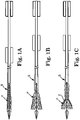
- As mentioned above, an outer sheath or catheter is conventionally employed to deliver a self-deploying vascular stent. Applying this same technique for the delivery of a self-deploying stented prosthetic heart valve, the high radial expansion force associated with the prosthesis is not problematic for complete deployment as the outer sheath is simply retracted in tension to allow the prosthetic heart valve to deploy. Were the conventional delivery system operated to only partially withdraw the outer sheath relative to the prosthesis, only the so-exposed distal region of the prosthetic would expand while the proximal region remains coupled to the delivery system. In theory, the outer sheath could simply be advanced distally to recapture the expanded region. Unfortunately, with conventional sheath configurations, attempting to compress the expanded region of the stented prosthetic heart valve by distally sliding the sheath is unlikely to be successful. The conventional delivery sheath cannot readily overcome the radial force of the expanded region of the prosthesis because, in effect, the sheath is placed into compression and will collapse due at least in part to the abrupt edge of the sheath being unable to cleanly slide over the expanded region of the prosthesis. This effect is illustrated in a simplified form in
FIGS. 1A-1C . Prior to deployment (FIG. 1A ), the stented prosthetic heart valve P is constrained within, and supports, the sheath S. With deployment (FIG. IB), the sheath S is distally retracted, and the prosthesis P partially deploys. Where an attempt made to "recapture" the prosthesis P by distally sliding the sheath (FIG. 1C ), a leading end E of the sheath S abruptly abuts against the enlarged diameter of the prosthesis P, such that the distal end E cannot readily slide over the prosthesis P. Further, the sheath S is no longer internally supported and the radially expanded bias of the prosthesis P causes the sheath S to buckle or collapse. - In light of the above, a need exists for a stented transcatheter prosthetic heart valve delivery system and method that satisfies the constraints associated with heart valve implantation and permits partial deployment and recapturing of the prosthesis.
- The invention is defined by the appended claims. Some aspects in accordance with principles of the present disclosure relate to a delivery system for percutaneously deploying a prosthetic heart valve. The prosthetic heart valve is radially self-expandable from a compressed arrangement to a natural arrangement. The delivery system includes an inner shaft assembly, a delivery sheath capsule, and a handle maintaining a first actuator coupled to the delivery sheath capsule and a second actuator coupled to the inner shaft assembly. The inner shaft assembly includes an intermediate region providing a coupling structure configured to selectively engage a prosthetic heart valve. The delivery sheath capsule is slidably disposed over the inner shaft assembly and is configured to compressively retain the prosthetic heart valve engaged with the coupling structure. With this construction, the delivery system is configured to provide a loaded state in which the capsule compressively retains the prosthetic heart valve over the inner shaft assembly. During use, the first actuator can be operated to facilitate sliding of the capsule relative to the prosthetic heart valve so as to at least partially deploy the prosthetic heart valve relative to the delivery sheath capsule. The second actuator is operated to apply proximal forces to the inner shaft assembly and the prosthetic heart valve relative to the delivery system to facilitate recapture of the prosthetic heart valve.
- Yet other aspects in accordance with principles of the present disclosure relate to a device for repairing a heart valve of a patient. The device includes a delivery system and a prosthetic heart valve. The delivery system includes the inner shaft assembly, the delivery sheath capsule, and the handle, including the first actuator and the second actuator, as described above. The prosthetic heart valve has a frame and a valve structure forming at least two valve leaflets attached to the frame. With this construction, the prosthetic heart valve is self-expandable from a compressed arrangement to a natural arrangement. With this construction, the device is configured to be transitionable between a loaded state, a partially deployed state, and a recapturing state. In the loaded state, the prosthetic heart valve is coupled to the intermediate region of the inner shaft assembly, with the capsule compressively retaining the prosthetic heart valve in the compressed arrangement. In the partially deployed state, the capsule is at least partially withdrawn from the prosthetic heart valve using the first actuator such that a distal region of the prosthetic heart valve is exposed relative to the capsule and self-expands. In the recapturing state, the second actuator is operated to position the delivery system along the distal exposed region of the prosthetic heart valve and surround the prosthetic heart valve, due to proximal forces placed on the inner shaft assembly using the second actuator.
- Yet other aspects in accordance with principles of the present disclosure relate to a method of deploying a prosthetic heart valve to an implantation site. The method includes receiving a delivery system loaded with a radially expandable prosthetic heart valve having a frame to which a valve structure is attached. The delivery system includes a delivery sheath capsule compressively containing the prosthetic heart valve in a compressed arrangement over an inner shaft assembly in a loaded state. The prosthetic heart valve is delivered, in the compressed arrangement, through a bodily lumen of the patient and to the implantation site via the delivery system in the loaded state. The capsule is proximally retracted relative to the prosthetic heart valve such that a distal region of the prosthetic heart valve is exposed distal the capsule. The exposed, distal region self-expands toward a deployed arrangement. A position of the partially deployed prosthetic heart valve relative to the implantation site is evaluated. Based upon the evaluation, the prosthetic heart valve is proximally advanced relative to the delivery system such that the delivery system is advanced over the prosthetic heart valve.
-
-
FIGS. 1A-1C are simplified side views illustrating deficiencies of existing delivery sheaths or catheters to effectuate recapture of a partially deployed prosthetic heart valve; -
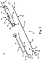
FIG. 2 is an exploded, perspective view of a delivery system in accordance with principles of the present disclosure and useful for percutaneously delivering a prosthetic heart valve to a heart valve implantation site; -
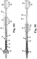
FIGS. 3A-3E are simplified, cross-sectional views illustrating use of the delivery system ofFIG. 2 in implanting a prosthetic heart valve, including partial deployment and repositioning thereof. - Current transcatheter heart valve delivery systems do not have the capability of transcatheter valve repositioning in the antegrade or retrograde directions after deployment. The delivery systems of the present disclosure overcome these problems, and permit the clinician to partially deploy the prosthetic heart valve, and prior to release, reposition or recapture and remove it. In general terms, the system functions by providing an actuator that serves to retract (i.e., by providing a proximal force thereto) a partially deployed prosthesis to effectuate recapturing of the partially deployed prosthetic heart valve.
- As referred to herein, the prosthetic heart valve as used in accordance with the various systems, devices, and methods of the present disclosure may include a wide variety of different configurations, such as a bioprosthetic heart valve having tissue leaflets or a synthetic heart valve having a polymeric, metallic, or tissue-engineered leaflets, and can be specifically configured for replacing any heart valve. Thus, the prosthetic heart valve useful with the systems, devices, and methods of the present disclosure can be generally used for replacement of a native aortic, mitral, pulmonic, or tricuspid valves, for use as a venous valve, or to replace a failed bioprosthesis, such as in the area of an aortic valve or mitral valve, for example.
- In general terms, the prosthetic heart valves of the present disclosure include a frame maintaining a valve structure (tissue or synthetic), with the frame having a normal, expanded arrangement and collapsible to a compressed arrangement for loading within the delivery system. The frame is normally constructed to self-deploy or self-expand when released from the delivery system. For example, the prosthetic heart valve useful with the present disclosure can be a prosthetic valve sold under the trade name CoreValve® available from Medtronic CoreValve, LLC. Other non-limiting examples of transcatheter heart valve prostheses useful with systems and methods of the present disclosure are described in
U.S. Publication Nos. 2006/0265056 ;2007/0239266 ; andUS 2007/0239269 . - The frames are support structures that comprise a number of struts or wire portions arranged relative to each other to provide a desired compressibility and strength to the prosthetic heart valve. In general terms, the frames of the present disclosure are generally tubular support structures having an internal area in which valve structure leaflets will be secured. The leaflets can be formed from a verity of materials, such as autologous tissue, xenograph material, or synthetics as are known in the art. The leaflets may be provided as a homogenous, biological valve structure, such as porcine, bovine, or equine valves. Alternatively, the leaflets can be provided independent of one another (e.g., bovine or equine paracardial leaflets) and subsequently assembled to the support structure of the frame. In another alternative, the frame and leaflets can be fabricated at the same time, such as may be accomplished using high-strength nano-manufactured NiTi films produced at Advance BioProsthetic Surfaces (ABPS), for example. The frame support structures are generally configured to accommodate at least two (typically three) leaftlets; however, replacement prosthetic heart valves of the types described herein can incorporate more or less than three leaflets.
- Some embodiments of the frames can be a series of wires or wire segments arranged such that they are capable of self-transitioning from a collapsed arrangement to a normal, radially expanded arrangement. In some constructions, a number of individual wires comprising the frame support structure can be formed of a metal or other material. These wires are arranged in such a way that the frame support structure allows for folding or compressing or crimping to the compressed arrangement in which the internal diameter is smaller than the internal diameter when in the natural, expanded arrangement. In the collapsed arrangement, such a frame support structure with attached valves can be mounted onto a delivery system. The frame support structures are configured so that they can be changed to their natural, expanded arrangement when desired, such as by the relative movement of one or more sheaths relative to a length of the frame.
- The wires of these frame support structures in embodiments of the present disclosure can be formed from a shape memory material such as a nickel titanium alloy (e.g., Nitinol™). With this material, the support structure is self-expandable from the compressed arrangement to the natural, expanded arrangement, such as by the application of heat, energy, and the like, or by the removal of external forces (e.g., compressive forces). This frame support structure can also be compressed and re-expanded multiple times without damaging the structure of the frame. In addition, the frame support structure of such an embodiment may be laser-cut from a single piece of material or may be assembled from a number of different components. For these types of frame structures, one example of a delivery system that can be used includes a catheter with a retractable sheath that covers the frame until it is to be deployed, at which point the sheath can be retracted to allow the frame to self-expand. Further details of such embodiments are discussed below.
- With the above in mind, one embodiment of a transcatheter stented prosthetic heart
valve delivery system 30 is shown inFIG. 2 . Thesystem 30 generally includes astability layer 32, aninner shaft assembly 34, adelivery sheath assembly 36, and ahandle 38. Details on the various components are provided below. In general terms, however, thedelivery system 30 provides a loaded state in which a prosthetic heart valve (not shown) is coupled to theinner shaft assembly 34 and compressively retained within acapsule 40 of thedelivery sheath assembly 36. Thedelivery sheath assembly 36 can be manipulated to withdraw thecapsule 40 proximally from the prosthetic heart valve via operation of thehandle 38, permitting the prosthesis to self-expand and release from theinner shaft assembly 34. Further, thehandle 38 can be operated to maneuver theinner shaft assembly 34 relative to thedelivery sheath assembly 36 to position thecapsule 40 over a partially deployed region of the prosthetic heart valve to facilitate recapturing of the prosthesis within thecapsule 40. In particular, proximal forces can be applied toinner shaft assembly 34 in order to facilitate recapture of the prosthetic heart valve. As a point of reference, various features of the components 32-38 reflected inFIG. 2 and described below can be modified or replaced with differing structures and/or mechanisms. Thus, the present disclosure is in no way limited to thestability layer 32, theinner shaft assembly 34, thedelivery sheath assembly 36, thehandle 38, etc., as shown and described below. More generally, delivery systems in accordance with the present disclosure provide features capable of compressively retaining a self-deploying, stented prosthetic heart valve (e.g., the capsule 40), a mechanism capable of effectuating release or deployment of the prosthesis (e.g., retracting the capsule 40), and an actuator (e.g., associated with handle 38) that retracts the prosthesis to promote recapture. - The
stability layer 32 illustratively includes ashaft 50, which forms a lumen 52 (referenced generally) sized to be slidably received over theinner shaft assembly 34, terminating at a distal end 54. Theshaft 50 can take many forms and in general provides structural integrity tosystem 30, yet allowing sufficient flexibility to maneuver thecapsule 40 to a target site (e.g., the aortic valve). To this end,shaft 50, in one embodiment, is formed of a polymeric material with an associated reinforcement layer. In other embodiments, thestability layer 32 can be eliminated. In yet other embodiments,stability layer 32 can facilitate recapture by providing columnar strength support to recapture the prosthetic heart valve, for example, by sliding overcapsule 40 or withincapsule 40. In other embodiments, whenstability layer 32 is configured to promote recapture, thestability layer 32 can be equipped to form a funnel shape at its distal end to recapture the prosthetic heart valve. - Returning to
FIG. 2 , the remaining components 34-38 of thedelivery system 30 can assume a variety of forms appropriate for percutaneously delivering and deploying a self-expanding prosthetic heart valve. For example, theinner shaft assembly 34 can have various constructions appropriate for supporting a prosthetic heart valve within thecapsule 40. In some embodiments, theinner shaft assembly 34 can include aretention member 100, anintermediate tube 102, and aproximal tube 104. In general terms, theretention member 100 can be akin to a plunger, and incorporates features for retaining the stented prosthetic heart valve within thecapsule 40 as described below. Thetube 102 connects theretention member 100 to theproximal tube 104, with theproximal tube 104, in turn, coupling theinner shaft assembly 34 with thehandle 38. The components 100-104 can combine to define a continuous lumen 106 (referenced generally) sized to slidably receive an auxiliary component such as a guide wire (not shown). - The
retention member 100 can include atip 110, asupport tube 112, and ahub 114. Thetip 110 forms or defines a nose cone having a distally tapering outer surface adapted to promote atraumatic contact with bodily tissue. Thetip 110 can be fixed or slidable relative to thesupport tube 112. Thesupport tube 112 extends proximally from thetip 110 and is configured to internally support a compressed prosthetic heart valve generally disposed thereover, and has a length and outer diameter corresponding with dimensional attributes of the selected prosthetic heart valve. Thehub 114 is attached to thesupport tube 112 opposite the tip 110 (e.g., an adhesive bond), and provides a coupling structure 120 (referenced generally) configured to selectively capture a corresponding feature of the prosthetic heart valve. Thecoupling structure 120 can assume various forms, and is generally located along an intermediate portion of theinner shaft assembly 34. In some constructions, thecoupling structure 120 includes one or more fingers sized to be received within corresponding apertures formed by the prosthetic heart valve frame (e.g., the prosthetic heart valve frame can form wire loops at a proximal end thereof that are received over respective ones of the fingers when compressed within the capsule 40). - The
intermediate tube 102 is formed of a flexible polymer material (e.g., PEEK), and is sized to be slidably received within thedelivery sheath assembly 36. Theproximal tube 104 can include, in some embodiments, a leadingportion 122 and a trailingportion 124. The leadingportion 122 serves as a transition between the intermediate andproximal tubes intermediate tube 102. The trailingportion 124 has a more rigid construction, configured for robust assembly with thehandle 38 such as a metal hypotube, at aproximal end 126. Other constructions are also envisioned. For example, in other embodiments, the intermediate andproximal tubes - The
delivery sheath assembly 36 includes thecapsule 40 and adelivery sheath shaft 130, and defines proximal anddistal ends capsule 40 extends distally from thedelivery shaft 130, and in some embodiments has a more stiffened construction (as compared to a stiffness of the delivery shaft 130) that exhibits sufficient radial or circumferential rigidity to overtly resist the expected expansive forces of the prosthetic heart valve in the compressed arrangement. For example, thedelivery shaft 130 can be a polymer tube embedded with a metal braiding, whereas thecapsule 40 is a laser-cut metal tube. Alternatively, thecapsule 40 and thedelivery shaft 130 can have a more uniform construction (e.g., a continuous polymer tube). Regardless, thecapsule 40 is constructed to compressively retain the prosthetic heart valve at a predetermined diameter when loaded within thecapsule 40, and thedelivery shaft 130 serves to connect thecapsule 40 with thehandle 38. The delivery shaft 130 (as well as the capsule 40) is constructed to be sufficiently flexible for passage through a patient's vasculature, yet exhibit sufficient longitudinal rigidity to effectuate desired axial movement of thecapsule 40. In other words, proximal retraction of thedelivery shaft 130 is directly transferred to thecapsule 40 and causes a corresponding proximal retraction of thecapsule 40. In other embodiments, thedelivery shaft 130 is further configured to transmit a rotational force or movement onto thecapsule 40. - The
handle 38 generally includes ahousing 140 and one or more actuator mechanisms (i.e., controls) 142 (referenced generally). Thehousing 140 maintains the actuator mechanism(s) 142, with thehandle 38 configured to facilitate sliding movement of thedelivery sheath assembly 36 relative to theinner shaft assembly 34, as well as provide proximal forces to theinner shaft assembly 34 relative to thedelivery sheath assembly 36 so as to retract the prosthetic heart valve into thecapsule 40. Thehousing 140 can have any shape or size appropriate for convenient handling by a user. In one simplified construction, a first,deployment actuator mechanism 142a includes a user interface or actuator (e.g., a deployment actuator) 144 slidably retained by thehousing 140 and coupled to a deliverysheath connector body 146. Theproximal end 132 of thedelivery sheath assembly 36 is connected to the deliverysheath connector body 146. - The
inner shaft assembly 34, and in particular theproximal tube 104, is slidably received within a passage 148 (referenced generally) of the deliverysheath connector body 146, and is rigidly coupled to thehousing 140 atproximal end 126. A second, recaptureactuator mechanism 142b (referenced generally) similarly includes a user interface or actuator (e.g., a recapture actuator) 150 slidably maintained by thehousing 140 and coupled to theinner shaft assembly 34 via one or more bodies (not shown), facilitating movement of theinner shaft assembly 34 with operation of the recaptureactuator 150. With this but one acceptable construction, thedeployment actuator 144 can be operated to effectuate axial movement of thedelivery sheath assembly 36 relative to theinner shaft assembly 34. Similarly, the recaptureactuator 150 can be manipulated to axially slide theinner shaft assembly 34 in a proximal direction relative to thedelivery sheath assembly 36. In particular, the recaptureactuator 150 can be axially slid relative to thehousing 140, transmitting proximal forces to theinner shaft assembly 34 and, in turn, the prosthetic heart valve coupled thereto. As such, the prosthetic heart valve can be recaptured bycapsule 40 for repositioning at a target site and/or retraction from a patient. - In one embodiment, recapture is facilitated by simultaneously providing distal forces to delivery sheath capsule 40 (i.e., by pushing
actuator 144 relative to housing 140) as indicated byarrow 152 and proximal forces to inner shaft assembly 34 (i.e., by pullingactuator 150 relative to housing 140) as indicated by arrow 154 (e.g., in a direction opposite to distal forces 152). In this embodiment, a ratio of distal forces 152 (i.e., applied to deployment actuator 144) to proximal forces 154 (i.e., applied to recapture actuator 150) can be varied to provide forces necessary to facilitate recapture. For example, in one example, thedistal forces 152 can be 25% of the recapture force while theproximal forces 154 are 75% of the recapture force. In another example, the ratio can be 50%distal forces proximal forces 154. In yet another example, the ratio can be distributed to be approximately 25%distal forces 152 and approximately 75%proximal forces 154. Other ratios can further be employed. -
FIG. 3A illustrates, in simplified form, loading of aprosthetic heart valve 160 within thedelivery system 30. In the loaded state ofFIG. 3A , the prosthetic heart valve (also referred to as a prosthesis) 160 is crimped over theinner shaft assembly 34, such that theprosthetic heart valve 160 engages thecoupling structure 120. Thecapsule 40 compressively contains theprosthetic heart valve 160 in the compressed arrangement.Actuators proximal end 162 and adistal end 164. As discussed above,deployment actuator 144 is coupled todelivery sheath assembly 36 and configured to move thedelivery sheath assembly 36 relative toinner shaft assembly 34. In particular, in order to movedelivery sheath assembly 36 with respect toinner shaft assembly 34,actuator 144 can be moved towardproximate end 162 of housing 140 (i.e., causing proximal movement of capsule 40) and/or towarddistal end 164 of housing 140 (i.e., causing distal movement of capsule 40). Likewise, recaptureactuator 150 is coupled toinner shaft assembly 34 and thusprosthetic heart valve 160 to move theinner shaft assembly 34 relative to thedelivery sheath assembly 36. In particular,actuator 150 can be moved away fromproximal end 162 ofhousing 140 to apply proximal forces toprosthetic heart valve 160 and towardproximal end 162 to apply distal forces toinner shaft assembly 34 andprosthetic heart valve 160. - To deploy the
prosthetic heart valve 160 from thedelivery system 30, thedelivery sheath assembly 36 is withdrawn from over theprosthetic heart valve 160, for example by proximally retracting thecapsule 40 by operatingactuator 144 towardproximal end 162 ofhousing 140, such that the capsuledistal end 134 is proximal thecoupling structure 120. Once thecapsule 40 is proximal thecoupling structure 120, theprosthetic heart valve 160 is allowed to self-expand to a natural arrangement thereby releasing from thedelivery system 30. - In some instances, a clinician may desire to only partially deploy the
prosthetic heart valve 160 and then evaluate before fully releasing theprosthetic heart valve 160. For example, thedelivery system 30 loaded with theprosthetic heart valve 160 can be employed as part of a method to repair a damaged heart valve of a patient. Under these circumstances, thedelivery system 30, in the loaded state, is advanced toward the native heart valve implantation target site, for example in a retrograde approach, through a cut-down to the femoral artery and into the patient's descending aorta. Thedelivery system 30 is then advanced usingtip 110, under fluoroscopic guidance, over the aortic arch, through the ascending aorta, and midway across the defective aortic valve (for aortic valve replacement). - Once positioning of the
delivery system 30 is estimated, thedelivery sheath assembly 36, and in particular thecapsule 40, is partially retracted relative to theprosthetic heart valve 160 as shown inFIG. 3B . In particular, a force as indicated byarrow 166 is applied toactuator 144 to slide theactuator 144 towardproximal end 162 ofhousing 140. Adistal region 170 of theprosthetic heart valve 160 is thus exteriorly exposed relative to thecapsule 40 and self-expands. In the partially deployed arrangement ofFIG. 3B , however, at least aproximal region 172 of theprosthesis 160 remains within the confines of thecapsule 40, and thus coupled to thedelivery system 30. As shown inFIG. 3C , further operation ofactuator 144 due to a force indicated byarrow 174 that movesactuator 144 towardproximal end 162 ofhousing 140 exposes a largerdistal region 170 ofprosthesis 160 whereas a smallproximal region 172 remains withincapsule 40. In this partially deployed state, a position of the stentedprosthetic heart valve 160 relative to the desired implantation site can again be evaluated. - In the event the clinician believes, based upon the above evaluation, that the
prosthesis 160 should be repositioned relative to the implantation site, theprosthetic heart valve 160 must first be contracted and "resheathed" by transitioning thedelivery system 30 to a recapturing state. As shown inFIG. 3D , theprosthetic heart valve 160 andinner shaft assembly 34, along withtip 110 andcoupling structure 120, are proximally advanced relative to thecapsule 40 by operating actuator 150 away fromproximal end 162, as indicated byarrow 180. In particular, proximal advancement of theprosthetic heart valve 160 causes thecapsule 40 to be maneuvered into contact with the exposeddistal region 170 of theprosthetic heart valve 160. Thecapsule 40 readily slides along a surface of theprosthetic heart valve 160. In a further embodiment, distal advancement of thecapsule 40 can also be provided by operation ofactuator 144 away fromproximal end 162 ofhousing 140, such force being indicated byarrow 182. By application offorce 180, potential trauma caused by exposeddistal region 170 can be reduced, as further distal forces can causedistal region 170 to become further embedded in tissue of a target site (e.g., the aortic arch). As discussed above, the recapture ofprosthetic heart valve 160 can further be facilitated by advancingstability layer 32 in addition to, or in replacement of,capsule 40 so as to promote recapture ofprosthetic heart valve 160. In this embodiment,layer 32 can provide columnar strength to recapturevalve 160.Stability layer 32 can be controlled byactuator 144 or a separate actuator, as desired. - Distal advancement of the
capsule 40 and proximal advancement of theprosthetic heart valve 160 continues untilcapsule 40 enclosesprosthetic heart valve 160, as shown inFIG. 3E . In particular,actuator 150 is further advanced away fromproximal end 162 ofhousing 140 due to a force indicated byarrow 184. In one embodiment, theforce 184 is simultaneously accompanied with a force indicated byarrow 186 onactuator 144 away fromproximal end 162 ofhousing 140. While thedistal region 170 may or may not slightly compress in response to placement within thecapsule 40, complete compression of theprosthetic heart valve 160 does not occur. However, due to the combinedforces prosthetic heart valve 160 are achieved. As shown inFIG. 3E , thecapsule 40 is distally advanced to a recapturing state, forming an enclosed region that can be repositioned and/or retracted. - Once the
prosthetic heart valve 160 is recaptured, thedelivery system 30 can be repositioned relative to the implantation site, and the process repeated until the clinician is comfortable with the achieved positioning. Alternatively, the resheathedprosthetic heart valve 160 can be removed from the patient. - The systems and methods of the present disclosure provide a marked improvement over previous designs. By providing separate actuators for the delivery sheath capsule and the inner shaft assembly, a partially deployed prosthesis is more readily recaptured.
Claims (7)
- A delivery system (30) for percutaneously deploying a stented prosthetic heart valve (160), the system (30) comprising:an inner shaft assembly (34) including an intermediate portion providing a coupling structure (120) configured to selectively engage a prosthetic heart valve (160);a delivery sheath assembly (36) slidably disposed over the inner shaft assembly (34), the delivery sheath assembly including a capsule (40) and a delivery sheath shaft (130), wherein the capsule extends distally from the delivery sheath shaft and is configured to compressively contain a prosthetic heart valve (160) engaged with the coupling structure (120); anda handle (38) coupled to the inner shaft assembly (34) and the delivery sheath capsule (40), the handle (38) maintaining a first actuator (142a, 144) selectively applying forces to the distal sheath capsule (40) and a second actuator (142b, 150) selectively applying forces to the inner shaft assembly (34) to retract the prosthetic heart valve (160) and promote recapture of the prosthetic heart valve (160) within the delivery system (30), wherein the handle (38) further includes a housing (140) and the first actuator (142a, 144) is operated relative to the housing (140) to apply forces to the delivery sheath capsule (40) and the second actuator (142b, 150) is moved relative to the housing (140) to apply forces to the inner shaft assembly (34), and wherein the housing (140) includes a proximal end and a distal end, the first actuator (142a, 144) being operated toward the proximal end to apply proximal forces to the delivery sheath capsule (40) and the second actuator (142b, 150) being operated away from the proximal end to apply proximal forces to the prosthetic heart valve (160).
- The system (30) of claim 1, wherein the system (30) is configured to provide a loaded state in which the capsule (40) compressively retains the stented prosthetic heart valve (160) over the inner shaft assembly (34).
- The system (30) of claim 2, wherein the system (30) is further configured to provide a partially deployed state in which the first actuator (142a, 144) is operated to apply proximal forces to the delivery sheath capsule (40) to expose a distal region of the prosthetic heart valve (160).
- The system (30) of claim 3, wherein the system (30) is further configured to provide a recapturing state in which after the system (30) is in the partially deployed state, transition to the recapturing state from the partially deployed state comprises the second actuator (142b, 150) being operated to apply proximal forces to the prosthetic heart valve (160) so that the delivery sheath capsule (40) slides over and compresses the prosthetic heart valve (160) is compressed and retained within the delivery system (30).
- The system (30) of claim 4, wherein the transition from the partially deployed state to the recapturing state further comprises the first actuator (142a, 144) being operated to apply distal forces to the delivery sheath capsule (40).
- A device for repairing a heart valve of a patient, the device comprising:the delivery system (30) according to claim 1 ; and
a prosthetic heart valve (160) having a frame and a valve structure attached to the frame and forming at least two valve leaflets, the prosthetic heart valve (160) being self-expandable from a compressed arrangement to a natural arrangement;wherein the device is configured to be transitionable between:a loaded state in which the prosthetic heart valve (160) engages the coupling structure (120) and is compressively retained within the capsule portion (40),a partially deployed state in which the capsule (40) is at least partially withdrawn from the prosthetic heart valve (160) upon operation of the first actuator such that a distal region of the prosthetic heart valve (160) is exposed relative to the capsule (40) and self-expands, anda recapturing state in which the prosthetic heart valve (160) is retracted into the delivery system (30) upon operation of the second actuator (142b, 150) to transmit proximal forces to the prosthetic heart valve (160). - The device of claim 6, wherein transition to the recapturing state further comprises the first actuator (142a, 144) being operated to apply distal forces to the delivery sheath capsule (40).
Priority Applications (2)
| Application Number | Priority Date | Filing Date | Title |
|---|---|---|---|
| EP19187569.9A EP3583919A1 (en) | 2010-04-09 | 2011-03-24 | Transcatheter prosthetic heart valve delivery system with recapturing feature |
| EP24161156.5A EP4353194A2 (en) | 2010-04-09 | 2011-03-24 | Transcatheter prosthetic heart valve delivery system with recapturing feature |
Applications Claiming Priority (2)
| Application Number | Priority Date | Filing Date | Title |
|---|---|---|---|
| US12/757,138 US8998980B2 (en) | 2010-04-09 | 2010-04-09 | Transcatheter prosthetic heart valve delivery system with recapturing feature and method |
| PCT/US2011/029811 WO2011126758A1 (en) | 2010-04-09 | 2011-03-24 | Transcatheter prosthetic heart valve delivery system with recapturing feature and method |
Related Child Applications (2)
| Application Number | Title | Priority Date | Filing Date |
|---|---|---|---|
| EP24161156.5A Division EP4353194A2 (en) | 2010-04-09 | 2011-03-24 | Transcatheter prosthetic heart valve delivery system with recapturing feature |
| EP19187569.9A Division EP3583919A1 (en) | 2010-04-09 | 2011-03-24 | Transcatheter prosthetic heart valve delivery system with recapturing feature |
Publications (2)
| Publication Number | Publication Date |
|---|---|
| EP2555710A1 EP2555710A1 (en) | 2013-02-13 |
| EP2555710B1 true EP2555710B1 (en) | 2019-07-24 |
Family
ID=44168269
Family Applications (3)
| Application Number | Title | Priority Date | Filing Date |
|---|---|---|---|
| EP11712427.1A Active EP2555710B1 (en) | 2010-04-09 | 2011-03-24 | Transcatheter prosthetic heart valve delivery system with recapturing feature |
| EP24161156.5A Pending EP4353194A2 (en) | 2010-04-09 | 2011-03-24 | Transcatheter prosthetic heart valve delivery system with recapturing feature |
| EP19187569.9A Pending EP3583919A1 (en) | 2010-04-09 | 2011-03-24 | Transcatheter prosthetic heart valve delivery system with recapturing feature |
Family Applications After (2)
| Application Number | Title | Priority Date | Filing Date |
|---|---|---|---|
| EP24161156.5A Pending EP4353194A2 (en) | 2010-04-09 | 2011-03-24 | Transcatheter prosthetic heart valve delivery system with recapturing feature |
| EP19187569.9A Pending EP3583919A1 (en) | 2010-04-09 | 2011-03-24 | Transcatheter prosthetic heart valve delivery system with recapturing feature |
Country Status (7)
| Country | Link |
|---|---|
| US (4) | US8998980B2 (en) |
| EP (3) | EP2555710B1 (en) |
| JP (1) | JP5803041B2 (en) |
| CN (1) | CN102883683B (en) |
| AU (1) | AU2011238752B2 (en) |
| DK (1) | DK2555710T3 (en) |
| WO (1) | WO2011126758A1 (en) |
Cited By (13)
| Publication number | Priority date | Publication date | Assignee | Title |
|---|---|---|---|---|
| US10856984B2 (en) | 2017-08-25 | 2020-12-08 | Neovasc Tiara Inc. | Sequentially deployed transcatheter mitral valve prosthesis |
| US10940001B2 (en) | 2012-05-30 | 2021-03-09 | Neovasc Tiara Inc. | Methods and apparatus for loading a prosthesis onto a delivery system |
| US11311376B2 (en) | 2019-06-20 | 2022-04-26 | Neovase Tiara Inc. | Low profile prosthetic mitral valve |
| US11357622B2 (en) | 2016-01-29 | 2022-06-14 | Neovase Tiara Inc. | Prosthetic valve for avoiding obstruction of outflow |
| US11389291B2 (en) | 2013-04-04 | 2022-07-19 | Neovase Tiara Inc. | Methods and apparatus for delivering a prosthetic valve to a beating heart |
| US11413139B2 (en) | 2011-11-23 | 2022-08-16 | Neovasc Tiara Inc. | Sequentially deployed transcatheter mitral valve prosthesis |
| US11419720B2 (en) | 2010-05-05 | 2022-08-23 | Neovasc Tiara Inc. | Transcatheter mitral valve prosthesis |
| US11464631B2 (en) | 2016-11-21 | 2022-10-11 | Neovasc Tiara Inc. | Methods and systems for rapid retraction of a transcatheter heart valve delivery system |
| US11491006B2 (en) | 2019-04-10 | 2022-11-08 | Neovasc Tiara Inc. | Prosthetic valve with natural blood flow |
| US11497602B2 (en) | 2012-02-14 | 2022-11-15 | Neovasc Tiara Inc. | Methods and apparatus for engaging a valve prosthesis with tissue |
| US11602429B2 (en) | 2019-04-01 | 2023-03-14 | Neovasc Tiara Inc. | Controllably deployable prosthetic valve |
| US11737872B2 (en) | 2018-11-08 | 2023-08-29 | Neovasc Tiara Inc. | Ventricular deployment of a transcatheter mitral valve prosthesis |
| US11779742B2 (en) | 2019-05-20 | 2023-10-10 | Neovasc Tiara Inc. | Introducer with hemostasis mechanism |
Families Citing this family (103)
| Publication number | Priority date | Publication date | Assignee | Title |
|---|---|---|---|---|
| WO2007058857A2 (en) | 2005-11-10 | 2007-05-24 | Arshad Quadri | Balloon-expandable, self-expanding, vascular prosthesis connecting stent |
| CN102292053A (en) | 2008-09-29 | 2011-12-21 | 卡迪尔克阀门技术公司 | Heart valve |
| US8790387B2 (en) | 2008-10-10 | 2014-07-29 | Edwards Lifesciences Corporation | Expandable sheath for introducing an endovascular delivery device into a body |
| CA2961053C (en) | 2009-04-15 | 2019-04-30 | Edwards Lifesciences Cardiaq Llc | Vascular implant and delivery system |
| US9730790B2 (en) | 2009-09-29 | 2017-08-15 | Edwards Lifesciences Cardiaq Llc | Replacement valve and method |
| US8449599B2 (en) | 2009-12-04 | 2013-05-28 | Edwards Lifesciences Corporation | Prosthetic valve for replacing mitral valve |
| US8998980B2 (en) | 2010-04-09 | 2015-04-07 | Medtronic, Inc. | Transcatheter prosthetic heart valve delivery system with recapturing feature and method |
| US8579963B2 (en) | 2010-04-13 | 2013-11-12 | Medtronic, Inc. | Transcatheter prosthetic heart valve delivery device with stability tube and method |
| AU2011271007A1 (en) | 2010-06-21 | 2013-01-31 | Cardiaq Valve Technologies, Inc. | Replacement heart valve |
| EP3459500B1 (en) | 2010-09-23 | 2020-09-16 | Edwards Lifesciences CardiAQ LLC | Replacement heart valves and delivery devices |
| US10016271B2 (en) | 2011-10-19 | 2018-07-10 | Twelve, Inc. | Prosthetic heart valve devices, prosthetic mitral valves and associated systems and methods |
| US9039757B2 (en) | 2011-10-19 | 2015-05-26 | Twelve, Inc. | Prosthetic heart valve devices, prosthetic mitral valves and associated systems and methods |
| US11202704B2 (en) | 2011-10-19 | 2021-12-21 | Twelve, Inc. | Prosthetic heart valve devices, prosthetic mitral valves and associated systems and methods |
| US9579198B2 (en) | 2012-03-01 | 2017-02-28 | Twelve, Inc. | Hydraulic delivery systems for prosthetic heart valve devices and associated methods |
| US20150088247A1 (en) * | 2012-03-23 | 2015-03-26 | Cytograft Tissue Engineering, Inc. | Tissue-engineered heart valve for transcatheter repair |
| JP6118894B2 (en) * | 2012-05-16 | 2017-04-19 | エッチエルティ インコーポレイテッドHlt, Inc. | Inverted transfer device and method for prosthesis |
| FR2996748B1 (en) | 2012-10-12 | 2015-02-06 | Cormove | DEVICE FOR TREATING A BLOOD CIRCULATION CONDUIT |
| US9907931B2 (en) | 2012-10-26 | 2018-03-06 | Medtronic, Inc. | Elastic introducer sheath |
| US9192751B2 (en) | 2012-10-26 | 2015-11-24 | Medtronic, Inc. | Elastic introducer sheath |
| US9675456B2 (en) | 2012-11-02 | 2017-06-13 | Medtronic, Inc. | Transcatheter valve prosthesis delivery system with recapturing feature and method |
| US9433521B2 (en) | 2012-11-27 | 2016-09-06 | Medtronic, Inc. | Distal tip for a delivery catheter |
| CN105263442B (en) * | 2013-02-04 | 2019-02-15 | 托尔福公司 | Hydraulic conveyor and correlation technique for artificial heart valve film device |
| US10583002B2 (en) | 2013-03-11 | 2020-03-10 | Neovasc Tiara Inc. | Prosthetic valve with anti-pivoting mechanism |
| US20140277427A1 (en) | 2013-03-14 | 2014-09-18 | Cardiaq Valve Technologies, Inc. | Prosthesis for atraumatically grasping intralumenal tissue and methods of delivery |
| US9681951B2 (en) | 2013-03-14 | 2017-06-20 | Edwards Lifesciences Cardiaq Llc | Prosthesis with outer skirt and anchors |
| US9730791B2 (en) | 2013-03-14 | 2017-08-15 | Edwards Lifesciences Cardiaq Llc | Prosthesis for atraumatically grasping intralumenal tissue and methods of delivery |
| EP2813195A1 (en) * | 2013-06-13 | 2014-12-17 | Cardiatis S.A. | Stent delivery system |
| KR101814945B1 (en) | 2013-10-15 | 2018-01-04 | 보스톤 싸이엔티픽 싸이메드 인코포레이티드 | Methods and systems for loading and delivering a stent |
| EP3107497B1 (en) | 2014-02-21 | 2020-07-22 | Edwards Lifesciences CardiAQ LLC | Delivery device for controlled deployment of a replacement valve |
| USD755384S1 (en) | 2014-03-05 | 2016-05-03 | Edwards Lifesciences Cardiaq Llc | Stent |
| US10195025B2 (en) | 2014-05-12 | 2019-02-05 | Edwards Lifesciences Corporation | Prosthetic heart valve |
| EP3128952A1 (en) | 2014-05-19 | 2017-02-15 | Edwards Lifesciences CardiAQ LLC | Replacement mitral valve with annular flap |
| US9532870B2 (en) | 2014-06-06 | 2017-01-03 | Edwards Lifesciences Corporation | Prosthetic valve for replacing a mitral valve |
| US9693860B2 (en) | 2014-12-01 | 2017-07-04 | Medtronic, Inc. | Segmented transcatheter valve prosthesis having an unsupported valve segment |
| US10478297B2 (en) | 2015-01-27 | 2019-11-19 | Medtronic Vascular, Inc. | Delivery system having an integral centering mechanism for positioning a valve prosthesis in situ |
| US10251748B2 (en) | 2015-02-12 | 2019-04-09 | Medtronic Vascular, Inc. | Centering devices for use with a valve prosthesis delivery system and methods of use thereof |
| US10231827B2 (en) | 2015-03-18 | 2019-03-19 | Medtronic Vascular, Inc. | Valve prostheses having an integral centering mechanism and methods of use thereof |
| US10327896B2 (en) | 2015-04-10 | 2019-06-25 | Edwards Lifesciences Corporation | Expandable sheath with elastomeric cross sectional portions |
| US10792471B2 (en) | 2015-04-10 | 2020-10-06 | Edwards Lifesciences Corporation | Expandable sheath |
| US10441416B2 (en) | 2015-04-21 | 2019-10-15 | Edwards Lifesciences Corporation | Percutaneous mitral valve replacement device |
| US10376363B2 (en) | 2015-04-30 | 2019-08-13 | Edwards Lifesciences Cardiaq Llc | Replacement mitral valve, delivery system for replacement mitral valve and methods of use |
| CA2990872C (en) | 2015-06-22 | 2022-03-22 | Edwards Lifescience Cardiaq Llc | Actively controllable heart valve implant and methods of controlling same |
| US10092400B2 (en) | 2015-06-23 | 2018-10-09 | Edwards Lifesciences Cardiaq Llc | Systems and methods for anchoring and sealing a prosthetic heart valve |
| US10154905B2 (en) | 2015-08-07 | 2018-12-18 | Medtronic Vascular, Inc. | System and method for deflecting a delivery catheter |
| US10117744B2 (en) | 2015-08-26 | 2018-11-06 | Edwards Lifesciences Cardiaq Llc | Replacement heart valves and methods of delivery |
| US10575951B2 (en) | 2015-08-26 | 2020-03-03 | Edwards Lifesciences Cardiaq Llc | Delivery device and methods of use for transapical delivery of replacement mitral valve |
| US10034747B2 (en) | 2015-08-27 | 2018-07-31 | Medtronic Vascular, Inc. | Prosthetic valve system having a docking component and a prosthetic valve component |
| US10350066B2 (en) | 2015-08-28 | 2019-07-16 | Edwards Lifesciences Cardiaq Llc | Steerable delivery system for replacement mitral valve and methods of use |
| JP7002451B2 (en) * | 2015-12-15 | 2022-01-20 | ニオバスク ティアラ インコーポレイテッド | Transseptal delivery system |
| US11833034B2 (en) | 2016-01-13 | 2023-12-05 | Shifamed Holdings, Llc | Prosthetic cardiac valve devices, systems, and methods |
| US10278852B2 (en) | 2016-03-10 | 2019-05-07 | Medtronic Vascular, Inc. | Steerable catheter with multiple bending radii via a steering mechanism with telescoping tubular components |
| EP3436124B1 (en) | 2016-03-31 | 2022-08-31 | Medtronic Vascular Inc. | Expandable introducer sheath having a steering mechanism |
| US10660776B2 (en) | 2016-04-11 | 2020-05-26 | Boston Scientific Scimed, Inc. | Stent delivery system with collapsible loading frame |
| USD815744S1 (en) | 2016-04-28 | 2018-04-17 | Edwards Lifesciences Cardiaq Llc | Valve frame for a delivery system |
| US10350062B2 (en) | 2016-07-21 | 2019-07-16 | Edwards Lifesciences Corporation | Replacement heart valve prosthesis |
| CA3033666A1 (en) | 2016-08-19 | 2018-02-22 | Edwards Lifesciences Corporation | Steerable delivery system for replacement mitral valve and methods of use |
| EP3964173B1 (en) | 2016-08-26 | 2024-04-10 | Edwards Lifesciences Corporation | Multi-portion replacement heart valve prosthesis |
| US10758348B2 (en) | 2016-11-02 | 2020-09-01 | Edwards Lifesciences Corporation | Supra and sub-annular mitral valve delivery system |
| US10493248B2 (en) | 2016-11-09 | 2019-12-03 | Medtronic Vascular, Inc. | Chordae tendineae management devices for use with a valve prosthesis delivery system and methods of use thereof |
| US10716666B2 (en) | 2016-12-05 | 2020-07-21 | Medtronic Vascular, Inc. | Prosthetic heart valve delivery system with controlled expansion |
| US10653523B2 (en) | 2017-01-19 | 2020-05-19 | 4C Medical Technologies, Inc. | Systems, methods and devices for delivery systems, methods and devices for implanting prosthetic heart valves |
| US10912919B2 (en) | 2017-01-23 | 2021-02-09 | Edwards Lifesciences Corporation | Expandable sheath |
| US10561495B2 (en) | 2017-01-24 | 2020-02-18 | 4C Medical Technologies, Inc. | Systems, methods and devices for two-step delivery and implantation of prosthetic heart valve |
| US10561497B2 (en) | 2017-03-07 | 2020-02-18 | Medtronic Vascular, Inc. | Delivery system having a short capsule segment and a cinch mechanism and methods of use thereof |
| EP3372199A1 (en) | 2017-03-08 | 2018-09-12 | Epygon | Delivery system for transcatheter prosthetic heart valves |
| US10799685B2 (en) | 2017-03-09 | 2020-10-13 | Edwards Lifesciences Corporation | Expandable sheath with longitudinally extending reinforcing members |
| CN110430843B (en) * | 2017-03-14 | 2022-06-07 | 波士顿科学国际有限公司 | Medical device shaft including a liner |
| US10575950B2 (en) | 2017-04-18 | 2020-03-03 | Twelve, Inc. | Hydraulic systems for delivering prosthetic heart valve devices and associated methods |
| US10646338B2 (en) * | 2017-06-02 | 2020-05-12 | Twelve, Inc. | Delivery systems with telescoping capsules for deploying prosthetic heart valve devices and associated methods |
| ES2923913T3 (en) | 2017-07-06 | 2022-10-03 | Edwards Lifesciences Corp | Steerable rail supply system |
| CN110913802B (en) * | 2017-07-18 | 2022-03-25 | 美敦力瓦斯科尔勒公司 | Transcatheter prosthetic heart valve delivery system with distal cutting assembly |
| US10722351B2 (en) | 2017-08-24 | 2020-07-28 | Medtronic Vascular, Inc. | Transcatheter prosthesis with sealing component, and systems and methods for delivering and deployment thereof |
| US10709556B2 (en) | 2017-08-24 | 2020-07-14 | Medtronic Vascular, Inc. | Transcatheter prosthesis with sealing component, and systems and methods for delivering and deployment thereof |
| CN117481869A (en) | 2018-01-25 | 2024-02-02 | 爱德华兹生命科学公司 | Delivery system for assisting in recapture and repositioning of replacement valves after deployment |
| WO2019161175A1 (en) | 2018-02-15 | 2019-08-22 | Boston Scientific Scimed, Inc. | Introducer with expandable capabilities |
| US10925728B2 (en) * | 2018-02-22 | 2021-02-23 | Medtronic Vascular, Inc. | Prosthetic heart valve delivery systems and methods |
| US11051934B2 (en) | 2018-02-28 | 2021-07-06 | Edwards Lifesciences Corporation | Prosthetic mitral valve with improved anchors and seal |
| WO2019195860A2 (en) | 2018-04-04 | 2019-10-10 | Vdyne, Llc | Devices and methods for anchoring transcatheter heart valve |
| CN111971001B (en) | 2018-04-09 | 2023-09-12 | 波士顿科学国际有限公司 | Stent delivery system with reduced deployment force |
| EP3773336A1 (en) | 2018-04-09 | 2021-02-17 | Edwards Lifesciences Corporation | Expandable sheath |
| US11786695B2 (en) | 2018-07-25 | 2023-10-17 | Edwards Lifesciences Corporation | Methods of making an expandable sheath |
| US11857441B2 (en) | 2018-09-04 | 2024-01-02 | 4C Medical Technologies, Inc. | Stent loading device |
| US11278437B2 (en) | 2018-12-08 | 2022-03-22 | Vdyne, Inc. | Compression capable annular frames for side delivery of transcatheter heart valve replacement |
| US11071627B2 (en) | 2018-10-18 | 2021-07-27 | Vdyne, Inc. | Orthogonally delivered transcatheter heart valve frame for valve in valve prosthesis |
| US11344413B2 (en) | 2018-09-20 | 2022-05-31 | Vdyne, Inc. | Transcatheter deliverable prosthetic heart valves and methods of delivery |
| US10321995B1 (en) | 2018-09-20 | 2019-06-18 | Vdyne, Llc | Orthogonally delivered transcatheter heart valve replacement |
| US10595994B1 (en) | 2018-09-20 | 2020-03-24 | Vdyne, Llc | Side-delivered transcatheter heart valve replacement |
| JP2022504241A (en) | 2018-10-05 | 2022-01-13 | シファメド・ホールディングス・エルエルシー | Artificial heart valve device, system, and method |
| US11109969B2 (en) | 2018-10-22 | 2021-09-07 | Vdyne, Inc. | Guidewire delivery of transcatheter heart valve |
| US11253359B2 (en) | 2018-12-20 | 2022-02-22 | Vdyne, Inc. | Proximal tab for side-delivered transcatheter heart valves and methods of delivery |
| US11185409B2 (en) | 2019-01-26 | 2021-11-30 | Vdyne, Inc. | Collapsible inner flow control component for side-delivered transcatheter heart valve prosthesis |
| US11273032B2 (en) | 2019-01-26 | 2022-03-15 | Vdyne, Inc. | Collapsible inner flow control component for side-deliverable transcatheter heart valve prosthesis |
| WO2020181154A2 (en) | 2019-03-05 | 2020-09-10 | Vdyne, Inc. | Tricuspid regurgitation control devices for orthogonal transcatheter heart valve prosthesis |
| US11076956B2 (en) | 2019-03-14 | 2021-08-03 | Vdyne, Inc. | Proximal, distal, and anterior anchoring tabs for side-delivered transcatheter mitral valve prosthesis |
| US11173027B2 (en) | 2019-03-14 | 2021-11-16 | Vdyne, Inc. | Side-deliverable transcatheter prosthetic valves and methods for delivering and anchoring the same |
| EP3941391A4 (en) | 2019-03-19 | 2022-11-23 | Shifamed Holdings, LLC | Prosthetic cardiac valve devices, systems, and methods |
| JP2022530764A (en) | 2019-05-04 | 2022-07-01 | ブイダイン,インコーポレイテッド | Tightening device and method for deploying a laterally delivered artificial heart valve with a native annulus. |
| EP4017442A4 (en) | 2019-08-20 | 2023-07-26 | Vdyne, Inc. | Delivery and retrieval devices and methods for side-deliverable transcatheter prosthetic valves |
| CN114630665A (en) | 2019-08-26 | 2022-06-14 | 维迪内股份有限公司 | Laterally deliverable transcatheter prosthetic valve and methods of delivery and anchoring thereof |
| US11622858B2 (en) * | 2019-10-09 | 2023-04-11 | Medtronic CV Luxembourg S.a.r.l. | Valve delivery system including foreshortening compensator for improved positioning accuracy |
| US11234813B2 (en) | 2020-01-17 | 2022-02-01 | Vdyne, Inc. | Ventricular stability elements for side-deliverable prosthetic heart valves and methods of delivery |
| US11931253B2 (en) | 2020-01-31 | 2024-03-19 | 4C Medical Technologies, Inc. | Prosthetic heart valve delivery system: ball-slide attachment |
| US20220339014A1 (en) * | 2021-04-23 | 2022-10-27 | DeepIn Technologies, LLC | Mechanical detachment system with a hold-release structure for deployment of endovascular devices |
Citations (1)
| Publication number | Priority date | Publication date | Assignee | Title |
|---|---|---|---|---|
| US20100004740A1 (en) * | 1999-11-17 | 2010-01-07 | Jacques Seguin | Prosthetic Valve for Transluminal Delivery |
Family Cites Families (45)
| Publication number | Priority date | Publication date | Assignee | Title |
|---|---|---|---|---|
| US5683451A (en) | 1994-06-08 | 1997-11-04 | Cardiovascular Concepts, Inc. | Apparatus and methods for deployment release of intraluminal prostheses |
| US5824041A (en) | 1994-06-08 | 1998-10-20 | Medtronic, Inc. | Apparatus and methods for placement and repositioning of intraluminal prostheses |
| US6077295A (en) * | 1996-07-15 | 2000-06-20 | Advanced Cardiovascular Systems, Inc. | Self-expanding stent delivery system |
| US5957949A (en) | 1997-05-01 | 1999-09-28 | World Medical Manufacturing Corp. | Percutaneous placement valve stent |
| US5906619A (en) | 1997-07-24 | 1999-05-25 | Medtronic, Inc. | Disposable delivery device for endoluminal prostheses |
| US6344044B1 (en) | 2000-02-11 | 2002-02-05 | Edwards Lifesciences Corp. | Apparatus and methods for delivery of intraluminal prosthesis |
| US20070027535A1 (en) * | 2005-07-28 | 2007-02-01 | Cook Incorporated | Implantable thromboresistant valve |
| US7052511B2 (en) * | 2002-04-04 | 2006-05-30 | Scimed Life Systems, Inc. | Delivery system and method for deployment of foreshortening endoluminal devices |
| US8721713B2 (en) | 2002-04-23 | 2014-05-13 | Medtronic, Inc. | System for implanting a replacement valve |
| US7947070B2 (en) | 2003-05-16 | 2011-05-24 | Boston Scientific Scimed, Inc. | Dilatation and stent delivery system and related methods |
| US8840663B2 (en) | 2003-12-23 | 2014-09-23 | Sadra Medical, Inc. | Repositionable heart valve method |
| DE602005022267D1 (en) | 2004-01-08 | 2010-08-26 | Merit Medical Systems Inc | HANDLE FOR AN IMPLANT DOCUMENT AND APPLICATION METHOD |
| AU2005209115A1 (en) * | 2004-01-30 | 2005-08-11 | Japan Tobacco Inc. | Anorectic compounds |
| US8128692B2 (en) * | 2004-02-27 | 2012-03-06 | Aortx, Inc. | Prosthetic heart valves, scaffolding structures, and systems and methods for implantation of same |
| US7909873B2 (en) * | 2006-12-15 | 2011-03-22 | Soteira, Inc. | Delivery apparatus and methods for vertebrostenting |
| US7462191B2 (en) | 2004-06-30 | 2008-12-09 | Edwards Lifesciences Pvt, Inc. | Device and method for assisting in the implantation of a prosthetic valve |
| US20060052867A1 (en) | 2004-09-07 | 2006-03-09 | Medtronic, Inc | Replacement prosthetic heart valve, system and method of implant |
| US20060116572A1 (en) | 2004-12-01 | 2006-06-01 | Case Brian C | Sensing delivery system for intraluminal medical devices |
| CN101076290B (en) * | 2004-12-09 | 2011-11-23 | 铸造品股份有限公司 | Aortic valve repair |
| DE102005003632A1 (en) | 2005-01-20 | 2006-08-17 | Fraunhofer-Gesellschaft zur Förderung der angewandten Forschung e.V. | Catheter for the transvascular implantation of heart valve prostheses |
| US7914569B2 (en) | 2005-05-13 | 2011-03-29 | Medtronics Corevalve Llc | Heart valve prosthesis and methods of manufacture and use |
| US7780723B2 (en) | 2005-06-13 | 2010-08-24 | Edwards Lifesciences Corporation | Heart valve delivery system |
| US20080188928A1 (en) | 2005-09-16 | 2008-08-07 | Amr Salahieh | Medical device delivery sheath |
| US8167932B2 (en) | 2005-10-18 | 2012-05-01 | Edwards Lifesciences Corporation | Heart valve delivery system with valve catheter |
| US20070213813A1 (en) | 2005-12-22 | 2007-09-13 | Symetis Sa | Stent-valves for valve replacement and associated methods and systems for surgery |
| US7740655B2 (en) | 2006-04-06 | 2010-06-22 | Medtronic Vascular, Inc. | Reinforced surgical conduit for implantation of a stented valve therein |
| US20070239269A1 (en) | 2006-04-07 | 2007-10-11 | Medtronic Vascular, Inc. | Stented Valve Having Dull Struts |
| US8535368B2 (en) * | 2006-05-19 | 2013-09-17 | Boston Scientific Scimed, Inc. | Apparatus for loading and delivering a stent |
| ATE556673T1 (en) | 2006-09-08 | 2012-05-15 | Edwards Lifesciences Corp | INTEGRATED HEART VALVE DELIVERY SYSTEM |
| BRPI0717540A2 (en) | 2006-09-28 | 2013-10-22 | Heart Leaflet Technologies Inc | SUPPLY INSTRUMENT FOR THE PERCUTANEOUS SUPPLY OF A PROSTHESIS |
| WO2008070797A2 (en) * | 2006-12-06 | 2008-06-12 | Medtronic Corevalve, Inc. | System and method for transapical delivery of an annulus anchored self-expanding valve |
| US8070799B2 (en) * | 2006-12-19 | 2011-12-06 | Sorin Biomedica Cardio S.R.L. | Instrument and method for in situ deployment of cardiac valve prostheses |
| US20080147181A1 (en) | 2006-12-19 | 2008-06-19 | Sorin Biomedica Cardio S.R.L. | Device for in situ axial and radial positioning of cardiac valve prostheses |
| US9295551B2 (en) * | 2007-04-13 | 2016-03-29 | Jenavalve Technology Gmbh | Methods of implanting an endoprosthesis |
| US20090093876A1 (en) | 2007-08-31 | 2009-04-09 | Edwards Lifesciences Corporation | Recoil inhibitor for prosthetic valve |
| US20090138079A1 (en) | 2007-10-10 | 2009-05-28 | Vector Technologies Ltd. | Prosthetic heart valve for transfemoral delivery |
| US20090171456A1 (en) * | 2007-12-28 | 2009-07-02 | Kveen Graig L | Percutaneous heart valve, system, and method |
| WO2009091509A1 (en) | 2008-01-16 | 2009-07-23 | St. Jude Medical, Inc. | Delivery and retrieval systems for collapsible/expandable prosthetic heart valves |
| WO2009094490A1 (en) * | 2008-01-24 | 2009-07-30 | Boston Scientific Scimed, Inc. | Apparatus and method for loading and delivering a stent having improved handles to control relative catheter component movement |
| US8157853B2 (en) * | 2008-01-24 | 2012-04-17 | Medtronic, Inc. | Delivery systems and methods of implantation for prosthetic heart valves |
| US9061119B2 (en) | 2008-05-09 | 2015-06-23 | Edwards Lifesciences Corporation | Low profile delivery system for transcatheter heart valve |
| CA2739961A1 (en) | 2008-10-10 | 2010-04-15 | Sadra Medical, Inc. | Medical devices and delivery systems for delivering medical devices |
| US8137398B2 (en) | 2008-10-13 | 2012-03-20 | Medtronic Ventor Technologies Ltd | Prosthetic valve having tapered tip when compressed for delivery |
| CN102548508B (en) | 2009-09-21 | 2015-06-03 | 麦德托尼克公司 | Stented transcatheter prosthetic heart valve delivery system and method |
| US8998980B2 (en) | 2010-04-09 | 2015-04-07 | Medtronic, Inc. | Transcatheter prosthetic heart valve delivery system with recapturing feature and method |
-
2010
- 2010-04-09 US US12/757,138 patent/US8998980B2/en active Active
-
2011
- 2011-03-24 DK DK11712427.1T patent/DK2555710T3/en active
- 2011-03-24 JP JP2013503776A patent/JP5803041B2/en not_active Expired - Fee Related
- 2011-03-24 WO PCT/US2011/029811 patent/WO2011126758A1/en active Application Filing
- 2011-03-24 CN CN201180023133.5A patent/CN102883683B/en active Active
- 2011-03-24 EP EP11712427.1A patent/EP2555710B1/en active Active
- 2011-03-24 AU AU2011238752A patent/AU2011238752B2/en not_active Ceased
- 2011-03-24 EP EP24161156.5A patent/EP4353194A2/en active Pending
- 2011-03-24 EP EP19187569.9A patent/EP3583919A1/en active Pending
-
2015
- 2015-03-09 US US14/641,679 patent/US9522063B2/en active Active
-
2016
- 2016-11-09 US US15/346,843 patent/US10456254B2/en active Active
-
2019
- 2019-10-23 US US16/661,389 patent/US11666438B2/en active Active
Patent Citations (1)
| Publication number | Priority date | Publication date | Assignee | Title |
|---|---|---|---|---|
| US20100004740A1 (en) * | 1999-11-17 | 2010-01-07 | Jacques Seguin | Prosthetic Valve for Transluminal Delivery |
Cited By (17)
| Publication number | Priority date | Publication date | Assignee | Title |
|---|---|---|---|---|
| US11419720B2 (en) | 2010-05-05 | 2022-08-23 | Neovasc Tiara Inc. | Transcatheter mitral valve prosthesis |
| US11413139B2 (en) | 2011-11-23 | 2022-08-16 | Neovasc Tiara Inc. | Sequentially deployed transcatheter mitral valve prosthesis |
| US11497602B2 (en) | 2012-02-14 | 2022-11-15 | Neovasc Tiara Inc. | Methods and apparatus for engaging a valve prosthesis with tissue |
| US10940001B2 (en) | 2012-05-30 | 2021-03-09 | Neovasc Tiara Inc. | Methods and apparatus for loading a prosthesis onto a delivery system |
| US11617650B2 (en) | 2012-05-30 | 2023-04-04 | Neovasc Tiara Inc. | Methods and apparatus for loading a prosthesis onto a delivery system |
| US11389294B2 (en) | 2012-05-30 | 2022-07-19 | Neovasc Tiara Inc. | Methods and apparatus for loading a prosthesis onto a delivery system |
| US11389291B2 (en) | 2013-04-04 | 2022-07-19 | Neovase Tiara Inc. | Methods and apparatus for delivering a prosthetic valve to a beating heart |
| US11357622B2 (en) | 2016-01-29 | 2022-06-14 | Neovase Tiara Inc. | Prosthetic valve for avoiding obstruction of outflow |
| US11464631B2 (en) | 2016-11-21 | 2022-10-11 | Neovasc Tiara Inc. | Methods and systems for rapid retraction of a transcatheter heart valve delivery system |
| US10856984B2 (en) | 2017-08-25 | 2020-12-08 | Neovasc Tiara Inc. | Sequentially deployed transcatheter mitral valve prosthesis |
| US11793640B2 (en) | 2017-08-25 | 2023-10-24 | Neovasc Tiara Inc. | Sequentially deployed transcatheter mitral valve prosthesis |
| US11737872B2 (en) | 2018-11-08 | 2023-08-29 | Neovasc Tiara Inc. | Ventricular deployment of a transcatheter mitral valve prosthesis |
| US11602429B2 (en) | 2019-04-01 | 2023-03-14 | Neovasc Tiara Inc. | Controllably deployable prosthetic valve |
| US11491006B2 (en) | 2019-04-10 | 2022-11-08 | Neovasc Tiara Inc. | Prosthetic valve with natural blood flow |
| US11779742B2 (en) | 2019-05-20 | 2023-10-10 | Neovasc Tiara Inc. | Introducer with hemostasis mechanism |
| US11311376B2 (en) | 2019-06-20 | 2022-04-26 | Neovase Tiara Inc. | Low profile prosthetic mitral valve |
| US11931254B2 (en) | 2019-06-20 | 2024-03-19 | Neovasc Tiara Inc. | Low profile prosthetic mitral valve |
Also Published As
| Publication number | Publication date |
|---|---|
| JP5803041B2 (en) | 2015-11-04 |
| US20200054452A1 (en) | 2020-02-20 |
| US20170049569A1 (en) | 2017-02-23 |
| AU2011238752B2 (en) | 2015-02-12 |
| US20150173895A1 (en) | 2015-06-25 |
| CN102883683B (en) | 2016-11-09 |
| WO2011126758A1 (en) | 2011-10-13 |
| US10456254B2 (en) | 2019-10-29 |
| US8998980B2 (en) | 2015-04-07 |
| US11666438B2 (en) | 2023-06-06 |
| EP2555710A1 (en) | 2013-02-13 |
| DK2555710T3 (en) | 2019-10-07 |
| US20110251681A1 (en) | 2011-10-13 |
| EP4353194A2 (en) | 2024-04-17 |
| US9522063B2 (en) | 2016-12-20 |
| CN102883683A (en) | 2013-01-16 |
| JP2013523329A (en) | 2013-06-17 |
| EP3583919A1 (en) | 2019-12-25 |
| AU2011238752A1 (en) | 2012-10-25 |
Similar Documents
| Publication | Publication Date | Title |
|---|---|---|
| US11666438B2 (en) | Transcatheter prosthetic heart valve delivery system with recapturing feature and method | |
| US10105223B2 (en) | Transcatheter prosthetic heart valve delivery system with recapturing feature | |
| US11833045B2 (en) | Transcatheter delivery system and method with controlled expansion and contraction of prosthetic heart valve | |
| US8986372B2 (en) | Transcatheter prosthetic heart valve delivery system with funnel recapturing feature and method | |
| EP2560579B1 (en) | Transcatheter prosthetic heart valve delivery system with expandable stability tube |
Legal Events
| Date | Code | Title | Description |
|---|---|---|---|
| PUAI | Public reference made under article 153(3) epc to a published international application that has entered the european phase |
Free format text: ORIGINAL CODE: 0009012 |
|
| 17P | Request for examination filed |
Effective date: 20121024 |
|
| AK | Designated contracting states |
Kind code of ref document: A1 Designated state(s): AL AT BE BG CH CY CZ DE DK EE ES FI FR GB GR HR HU IE IS IT LI LT LU LV MC MK MT NL NO PL PT RO RS SE SI SK SM TR |
|
| DAX | Request for extension of the european patent (deleted) | ||
| 17Q | First examination report despatched |
Effective date: 20140522 |
|
| RIC1 | Information provided on ipc code assigned before grant |
Ipc: A61F 2/24 20060101AFI20180115BHEP |
|
| GRAP | Despatch of communication of intention to grant a patent |
Free format text: ORIGINAL CODE: EPIDOSNIGR1 |
|
| STAA | Information on the status of an ep patent application or granted ep patent |
Free format text: STATUS: GRANT OF PATENT IS INTENDED |
|
| INTG | Intention to grant announced |
Effective date: 20180305 |
|
| GRAJ | Information related to disapproval of communication of intention to grant by the applicant or resumption of examination proceedings by the epo deleted |
Free format text: ORIGINAL CODE: EPIDOSDIGR1 |
|
| STAA | Information on the status of an ep patent application or granted ep patent |
Free format text: STATUS: EXAMINATION IS IN PROGRESS |
|
| INTC | Intention to grant announced (deleted) | ||
| GRAP | Despatch of communication of intention to grant a patent |
Free format text: ORIGINAL CODE: EPIDOSNIGR1 |
|
| STAA | Information on the status of an ep patent application or granted ep patent |
Free format text: STATUS: GRANT OF PATENT IS INTENDED |
|
| INTG | Intention to grant announced |
Effective date: 20190220 |
|
| GRAS | Grant fee paid |
Free format text: ORIGINAL CODE: EPIDOSNIGR3 |
|
| GRAA | (expected) grant |
Free format text: ORIGINAL CODE: 0009210 |
|
| STAA | Information on the status of an ep patent application or granted ep patent |
Free format text: STATUS: THE PATENT HAS BEEN GRANTED |
|
| AK | Designated contracting states |
Kind code of ref document: B1 Designated state(s): AL AT BE BG CH CY CZ DE DK EE ES FI FR GB GR HR HU IE IS IT LI LT LU LV MC MK MT NL NO PL PT RO RS SE SI SK SM TR |
|
| REG | Reference to a national code |
Ref country code: GB Ref legal event code: FG4D |
|
| REG | Reference to a national code |
Ref country code: CH Ref legal event code: EP |
|
| REG | Reference to a national code |
Ref country code: DE Ref legal event code: R096 Ref document number: 602011060646 Country of ref document: DE |
|
| REG | Reference to a national code |
Ref country code: AT Ref legal event code: REF Ref document number: 1157293 Country of ref document: AT Kind code of ref document: T Effective date: 20190815 |
|
| REG | Reference to a national code |
Ref country code: IE Ref legal event code: FG4D |
|
| REG | Reference to a national code |
Ref country code: CH Ref legal event code: NV Representative=s name: RENTSCH PARTNER AG, CH |
|
| REG | Reference to a national code |
Ref country code: DK Ref legal event code: T3 Effective date: 20191004 |
|
| REG | Reference to a national code |
Ref country code: NL Ref legal event code: FP |
|
| REG | Reference to a national code |
Ref country code: LT Ref legal event code: MG4D |
|
| PG25 | Lapsed in a contracting state [announced via postgrant information from national office to epo] |
Ref country code: LT Free format text: LAPSE BECAUSE OF FAILURE TO SUBMIT A TRANSLATION OF THE DESCRIPTION OR TO PAY THE FEE WITHIN THE PRESCRIBED TIME-LIMIT Effective date: 20190724 Ref country code: FI Free format text: LAPSE BECAUSE OF FAILURE TO SUBMIT A TRANSLATION OF THE DESCRIPTION OR TO PAY THE FEE WITHIN THE PRESCRIBED TIME-LIMIT Effective date: 20190724 Ref country code: PT Free format text: LAPSE BECAUSE OF FAILURE TO SUBMIT A TRANSLATION OF THE DESCRIPTION OR TO PAY THE FEE WITHIN THE PRESCRIBED TIME-LIMIT Effective date: 20191125 Ref country code: SE Free format text: LAPSE BECAUSE OF FAILURE TO SUBMIT A TRANSLATION OF THE DESCRIPTION OR TO PAY THE FEE WITHIN THE PRESCRIBED TIME-LIMIT Effective date: 20190724 Ref country code: HR Free format text: LAPSE BECAUSE OF FAILURE TO SUBMIT A TRANSLATION OF THE DESCRIPTION OR TO PAY THE FEE WITHIN THE PRESCRIBED TIME-LIMIT Effective date: 20190724 Ref country code: BG Free format text: LAPSE BECAUSE OF FAILURE TO SUBMIT A TRANSLATION OF THE DESCRIPTION OR TO PAY THE FEE WITHIN THE PRESCRIBED TIME-LIMIT Effective date: 20191024 Ref country code: NO Free format text: LAPSE BECAUSE OF FAILURE TO SUBMIT A TRANSLATION OF THE DESCRIPTION OR TO PAY THE FEE WITHIN THE PRESCRIBED TIME-LIMIT Effective date: 20191024 |
|
| PG25 | Lapsed in a contracting state [announced via postgrant information from national office to epo] |
Ref country code: ES Free format text: LAPSE BECAUSE OF FAILURE TO SUBMIT A TRANSLATION OF THE DESCRIPTION OR TO PAY THE FEE WITHIN THE PRESCRIBED TIME-LIMIT Effective date: 20190724 Ref country code: AL Free format text: LAPSE BECAUSE OF FAILURE TO SUBMIT A TRANSLATION OF THE DESCRIPTION OR TO PAY THE FEE WITHIN THE PRESCRIBED TIME-LIMIT Effective date: 20190724 Ref country code: LV Free format text: LAPSE BECAUSE OF FAILURE TO SUBMIT A TRANSLATION OF THE DESCRIPTION OR TO PAY THE FEE WITHIN THE PRESCRIBED TIME-LIMIT Effective date: 20190724 Ref country code: IS Free format text: LAPSE BECAUSE OF FAILURE TO SUBMIT A TRANSLATION OF THE DESCRIPTION OR TO PAY THE FEE WITHIN THE PRESCRIBED TIME-LIMIT Effective date: 20191124 Ref country code: RS Free format text: LAPSE BECAUSE OF FAILURE TO SUBMIT A TRANSLATION OF THE DESCRIPTION OR TO PAY THE FEE WITHIN THE PRESCRIBED TIME-LIMIT Effective date: 20190724 Ref country code: GR Free format text: LAPSE BECAUSE OF FAILURE TO SUBMIT A TRANSLATION OF THE DESCRIPTION OR TO PAY THE FEE WITHIN THE PRESCRIBED TIME-LIMIT Effective date: 20191025 |
|
| PG25 | Lapsed in a contracting state [announced via postgrant information from national office to epo] |
Ref country code: TR Free format text: LAPSE BECAUSE OF FAILURE TO SUBMIT A TRANSLATION OF THE DESCRIPTION OR TO PAY THE FEE WITHIN THE PRESCRIBED TIME-LIMIT Effective date: 20190724 |
|
| PG25 | Lapsed in a contracting state [announced via postgrant information from national office to epo] |
Ref country code: PL Free format text: LAPSE BECAUSE OF FAILURE TO SUBMIT A TRANSLATION OF THE DESCRIPTION OR TO PAY THE FEE WITHIN THE PRESCRIBED TIME-LIMIT Effective date: 20190724 Ref country code: EE Free format text: LAPSE BECAUSE OF FAILURE TO SUBMIT A TRANSLATION OF THE DESCRIPTION OR TO PAY THE FEE WITHIN THE PRESCRIBED TIME-LIMIT Effective date: 20190724 Ref country code: RO Free format text: LAPSE BECAUSE OF FAILURE TO SUBMIT A TRANSLATION OF THE DESCRIPTION OR TO PAY THE FEE WITHIN THE PRESCRIBED TIME-LIMIT Effective date: 20190724 Ref country code: IT Free format text: LAPSE BECAUSE OF FAILURE TO SUBMIT A TRANSLATION OF THE DESCRIPTION OR TO PAY THE FEE WITHIN THE PRESCRIBED TIME-LIMIT Effective date: 20190724 |
|
| PGFP | Annual fee paid to national office [announced via postgrant information from national office to epo] |
Ref country code: IE Payment date: 20200227 Year of fee payment: 10 Ref country code: DK Payment date: 20200225 Year of fee payment: 10 Ref country code: AT Payment date: 20200227 Year of fee payment: 10 |
|
| PG25 | Lapsed in a contracting state [announced via postgrant information from national office to epo] |
Ref country code: SM Free format text: LAPSE BECAUSE OF FAILURE TO SUBMIT A TRANSLATION OF THE DESCRIPTION OR TO PAY THE FEE WITHIN THE PRESCRIBED TIME-LIMIT Effective date: 20190724 Ref country code: SK Free format text: LAPSE BECAUSE OF FAILURE TO SUBMIT A TRANSLATION OF THE DESCRIPTION OR TO PAY THE FEE WITHIN THE PRESCRIBED TIME-LIMIT Effective date: 20190724 Ref country code: IS Free format text: LAPSE BECAUSE OF FAILURE TO SUBMIT A TRANSLATION OF THE DESCRIPTION OR TO PAY THE FEE WITHIN THE PRESCRIBED TIME-LIMIT Effective date: 20200224 Ref country code: CZ Free format text: LAPSE BECAUSE OF FAILURE TO SUBMIT A TRANSLATION OF THE DESCRIPTION OR TO PAY THE FEE WITHIN THE PRESCRIBED TIME-LIMIT Effective date: 20190724 |
|
| PGFP | Annual fee paid to national office [announced via postgrant information from national office to epo] |
Ref country code: CH Payment date: 20200221 Year of fee payment: 10 |
|
| REG | Reference to a national code |
Ref country code: DE Ref legal event code: R097 Ref document number: 602011060646 Country of ref document: DE |
|
| PLBE | No opposition filed within time limit |
Free format text: ORIGINAL CODE: 0009261 |
|
| STAA | Information on the status of an ep patent application or granted ep patent |
Free format text: STATUS: NO OPPOSITION FILED WITHIN TIME LIMIT |
|
| REG | Reference to a national code |
Ref country code: AT Ref legal event code: UEP Ref document number: 1157293 Country of ref document: AT Kind code of ref document: T Effective date: 20190724 |
|
| PG2D | Information on lapse in contracting state deleted |
Ref country code: IS |
|
| 26N | No opposition filed |
Effective date: 20200603 |
|
| PG25 | Lapsed in a contracting state [announced via postgrant information from national office to epo] |
Ref country code: SI Free format text: LAPSE BECAUSE OF FAILURE TO SUBMIT A TRANSLATION OF THE DESCRIPTION OR TO PAY THE FEE WITHIN THE PRESCRIBED TIME-LIMIT Effective date: 20190724 |
|
| PG25 | Lapsed in a contracting state [announced via postgrant information from national office to epo] |
Ref country code: MC Free format text: LAPSE BECAUSE OF FAILURE TO SUBMIT A TRANSLATION OF THE DESCRIPTION OR TO PAY THE FEE WITHIN THE PRESCRIBED TIME-LIMIT Effective date: 20190724 |
|
| REG | Reference to a national code |
Ref country code: BE Ref legal event code: MM Effective date: 20200331 |
|
| PG25 | Lapsed in a contracting state [announced via postgrant information from national office to epo] |
Ref country code: LU Free format text: LAPSE BECAUSE OF NON-PAYMENT OF DUE FEES Effective date: 20200324 |
|
| PG25 | Lapsed in a contracting state [announced via postgrant information from national office to epo] |
Ref country code: BE Free format text: LAPSE BECAUSE OF NON-PAYMENT OF DUE FEES Effective date: 20200331 |
|
| GBPC | Gb: european patent ceased through non-payment of renewal fee |
Effective date: 20200324 |
|
| PG25 | Lapsed in a contracting state [announced via postgrant information from national office to epo] |
Ref country code: GB Free format text: LAPSE BECAUSE OF NON-PAYMENT OF DUE FEES Effective date: 20200324 |
|
| REG | Reference to a national code |
Ref country code: CH Ref legal event code: PL |
|
| REG | Reference to a national code |
Ref country code: DK Ref legal event code: EBP Effective date: 20210331 |
|
| REG | Reference to a national code |
Ref country code: AT Ref legal event code: MM01 Ref document number: 1157293 Country of ref document: AT Kind code of ref document: T Effective date: 20210324 |
|
| PG25 | Lapsed in a contracting state [announced via postgrant information from national office to epo] |
Ref country code: IE Free format text: LAPSE BECAUSE OF NON-PAYMENT OF DUE FEES Effective date: 20210324 Ref country code: CH Free format text: LAPSE BECAUSE OF NON-PAYMENT OF DUE FEES Effective date: 20210331 Ref country code: AT Free format text: LAPSE BECAUSE OF NON-PAYMENT OF DUE FEES Effective date: 20210324 Ref country code: LI Free format text: LAPSE BECAUSE OF NON-PAYMENT OF DUE FEES Effective date: 20210331 |
|
| PG25 | Lapsed in a contracting state [announced via postgrant information from national office to epo] |
Ref country code: DK Free format text: LAPSE BECAUSE OF NON-PAYMENT OF DUE FEES Effective date: 20210331 |
|
| PG25 | Lapsed in a contracting state [announced via postgrant information from national office to epo] |
Ref country code: MT Free format text: LAPSE BECAUSE OF FAILURE TO SUBMIT A TRANSLATION OF THE DESCRIPTION OR TO PAY THE FEE WITHIN THE PRESCRIBED TIME-LIMIT Effective date: 20190724 Ref country code: CY Free format text: LAPSE BECAUSE OF FAILURE TO SUBMIT A TRANSLATION OF THE DESCRIPTION OR TO PAY THE FEE WITHIN THE PRESCRIBED TIME-LIMIT Effective date: 20190724 |
|
| PG25 | Lapsed in a contracting state [announced via postgrant information from national office to epo] |
Ref country code: MK Free format text: LAPSE BECAUSE OF FAILURE TO SUBMIT A TRANSLATION OF THE DESCRIPTION OR TO PAY THE FEE WITHIN THE PRESCRIBED TIME-LIMIT Effective date: 20190724 |
|
| PGFP | Annual fee paid to national office [announced via postgrant information from national office to epo] |
Ref country code: NL Payment date: 20230221 Year of fee payment: 13 |
|
| PGFP | Annual fee paid to national office [announced via postgrant information from national office to epo] |
Ref country code: FR Payment date: 20230222 Year of fee payment: 13 |
|
| PGFP | Annual fee paid to national office [announced via postgrant information from national office to epo] |
Ref country code: DE Payment date: 20230221 Year of fee payment: 13 |
|
| PGFP | Annual fee paid to national office [announced via postgrant information from national office to epo] |
Ref country code: NL Payment date: 20240220 Year of fee payment: 14 |