EP2555366A2 - Capture device, in particular for high voltage cable - Google Patents
Capture device, in particular for high voltage cable Download PDFInfo
- Publication number
- EP2555366A2 EP2555366A2 EP12005660A EP12005660A EP2555366A2 EP 2555366 A2 EP2555366 A2 EP 2555366A2 EP 12005660 A EP12005660 A EP 12005660A EP 12005660 A EP12005660 A EP 12005660A EP 2555366 A2 EP2555366 A2 EP 2555366A2
- Authority
- EP
- European Patent Office
- Prior art keywords
- ring
- outer ring
- core ring
- platform
- core
- Prior art date
- Legal status (The legal status is an assumption and is not a legal conclusion. Google has not performed a legal analysis and makes no representation as to the accuracy of the status listed.)
- Granted
Links
Images

Classifications
-
- H—ELECTRICITY
- H02—GENERATION; CONVERSION OR DISTRIBUTION OF ELECTRIC POWER
- H02G—INSTALLATION OF ELECTRIC CABLES OR LINES, OR OF COMBINED OPTICAL AND ELECTRIC CABLES OR LINES
- H02G15/00—Cable fittings
- H02G15/02—Cable terminations
- H02G15/06—Cable terminating boxes, frames or other structures
-
- H—ELECTRICITY
- H02—GENERATION; CONVERSION OR DISTRIBUTION OF ELECTRIC POWER
- H02G—INSTALLATION OF ELECTRIC CABLES OR LINES, OR OF COMBINED OPTICAL AND ELECTRIC CABLES OR LINES
- H02G15/00—Cable fittings
- H02G15/08—Cable junctions
- H02G15/10—Cable junctions protected by boxes, e.g. by distribution, connection or junction boxes
- H02G15/12—Cable junctions protected by boxes, e.g. by distribution, connection or junction boxes for incorporating transformers, loading coils or amplifiers
- H02G15/14—Cable junctions protected by boxes, e.g. by distribution, connection or junction boxes for incorporating transformers, loading coils or amplifiers specially adapted for submarine cables
-
- H—ELECTRICITY
- H02—GENERATION; CONVERSION OR DISTRIBUTION OF ELECTRIC POWER
- H02G—INSTALLATION OF ELECTRIC CABLES OR LINES, OR OF COMBINED OPTICAL AND ELECTRIC CABLES OR LINES
- H02G9/00—Installations of electric cables or lines in or on the ground or water
- H02G9/12—Installations of electric cables or lines in or on the ground or water supported on or from floats, e.g. in water
Definitions
- the invention relates to an interceptor for a guided through the bottom of an opening of a horizontal platform, formed with a reinforcing layer, free-hanging object, in particular for a power cable.
- a puller head is used to engage the armor layer of the power cable and pick up the weight of the hanging cable.
- the mechanical tensile forces are absorbed by the reinforcing layer, with as few forces as possible being transmitted to the inner cable structure.
- the power cable is fixed by means of a temporary or a permanent cable-catching device (English 'hang-off').
- the DE 1042063 B describes an interceptor for an overseas cable with a large number of individual segments.
- the device has the goal to clamp all reinforcement wires as possible with the same tensile stress. Therefore, the structure consists of many parts and the assembly is accordingly very expensive.
- the font US 2006-0193572 A1 shows an interceptor for a bottomed through an opening data cable with clamping means for a reinforcing layer and supporting means for supporting the device on a platform. Further details can not be found in the text.
- the reinforcing wires are widened conically and bent over a ring. Bending occurs from the larger diameter of the widening inward towards the cable surface.
- the reinforcing wires are finally permanently clamped between two conically and mutually matching clamping means and a cover plate and thus mechanically secured the cable ( US 2010-0314151 A1 ).
- Narrow clamping cables and trapping means which are made of steel and usually made of steel, have the disadvantage that during operation of the cable, magnetic losses occur which lead to power losses and thermal stress on the cable in the area of the support.
- sealing arrangements published for the passage of an electric cable into a submerged apparatus housing.
- a first example shows the GB 1571679 A in which one or two layers of reinforcing elements are used.
- Another example is from the DE 832009 B known. These arrangements are used to seal against a prevailing pressure under water.
- the strain relief or interception of the cable weight is achieved with many items that are fixed together.
- the clamping comes about by the expended forces in the screwing of the individual parts. A control of the clamping forces to avoid excessive deformation of the reinforcing elements is not provided.
- the reinforcing elements are wrapped around the core ring from the inner surface of a core ring to the outer surface of the core ring.
- the invention has for its object to provide an interception device that is easy to assemble and disassemble and in which the reinforcing elements are braced as gently as possible.
- the interceptor consists of only a few individual parts, of which an outer ring and support means are connected directly or indirectly fixedly to the platform, and a core or inner ring wrapped by Arm michsdrähten lying alone in the pulling direction of the elongated object in the outer ring in automatic clamping contact and holding function of Arm michsdrähte with the outer ring is.
- the weight of the object is absorbed by a (temporary) holding means.
- the article is pulled from below through an opening of the platform up and held.
- the reinforcing wires are wrapped around the core ring and received by releasing the holding means from the outer ring by clamping.
- clamping When clamping the full tensile load from the holding means on the interceptor over. Due to the tensile force of the free-hanging object core ring and outer ring are pressed together. The clamping is thus zugkrafttouch.
- the weight of the elongated object received by the intercepting device is taken over by a (temporary) device, thus relieving the intercepting device of its full weight.
- the tensile load is practically zero, whereby the clamping between the core ring and outer ring dissolves.
- the fixing elements of the interceptor can be removed.
- the weight of the article can be picked up on the now exposed armor wires.
- the system automatically adapts to changing load conditions.
- the clamping is dependent on the glass.
- the outer ring is fixed on the support means (Fixierklalen) in its position.
- the holding force remains the same.
- a pre-damage to the reinforcing wires by applying the clamping forces via tools is excluded.
- the interceptor is proposed for an elongate object formed from below through an opening of a horizontal platform and formed with a reinforcing layer.
- the object develops its traction by its own weight perpendicular to the platform.
- the interceptor comprises armor layer clamping means and support means for supporting the interceptor on the platform.
- the clamping means comprise a core ring, which surrounds the article and is surrounded by elements of the reinforcing layer, which abuts the reinforcing layer, and further connected to the platform via supporting means firmly connected, surrounding the object outer ring.
- the core ring is received in the pulling direction of the object from the outer ring.
- the interceptor may be formed with preferred embodiments.
- the features of the invention mentioned below may be used individually or together in various developments.
- the formation of the core ring as a torus, preferably with elliptical cross-section is essential.
- the reinforcement attempts to change its fixed shape from a large radius of curvature to a small radius of curvature and again to a large radius of curvature. This costs energy, which must be charged to the nip.
- the inner surface of the outer ring is formed such that the core ring in the pulling direction of the article in the outer ring can be inserted.
- the largest dimension of the core ring diameter is greater than the smallest dimension of the inner diameter of the outer ring. The core ring can not slip through the outer ring.
- the core ring is present as a torus, whereby its outer surface is convex.
- the torus may have an elliptical cross-section with the major axis of the ellipse being parallel to the axis of the article.
- a relation between 1.5: 1 and 2: 1 can be selected, for example a ratio of 1.7: 1.
- the surface of the core ring can be provided with grooves or grooves that there is an increased stiction between Arm mich distrdrähten and core ring.
- the reinforcing elements exposed from the reinforcing layer are laid over the core ring and returned against their original orientation.
- the wrapping of the reinforcing elements around the core ring is more than 180 °.
- the reinforcing elements come to lie between an outer surface of the core ring and an inner surface of the outer ring. The clamping arises after release of the temporarily carried object and is thus karkraftpin.
- the inner surface of the outer ring should be formed like a shell for receiving the core ring, wherein preferably the inner surface of the outer ring is conically widening in the direction of the located above the platform end of the article is formed.
- the conical expansion should be within an angular range of 6 ° to 12 °.
- the lying between the generatrices of the cone half angle is meant.
- the outer ring should have holes for synchronbefest only with the support means.
- Core ring and outer ring are formed from at least two identical segment elements.
- the respective rings are wrapped around the elongated object from the outside, wherein they can not be formed as a solid ring, but from parts of the respective ring, preferably namely identical segment elements.
- the elements each comprise a circular sector of 120 °.
- the segment elements of the core ring preferably consist of three ring elements with an elliptical cross-section. These ring elements are connected by three Unterschraubemia, whereby a full ring is formed, whose body has the elliptical cross section, and wherein the major axis of the ellipse is parallel to the axis of the elongated object.
- the segment elements of the outer ring preferably consist of three ring segments, which are screwed against each other via flanges.
- the interception device can be raised and secured directly in the region of a platform opening on the platform.
- a base plate provided with a bore for the passage of the article can be fastened on the opening of the platform.
- the base plate should have holes for the screw fastening with the support means.
- the support means may be in the form of a plurality of fixing columns or in the form of part-cylindrical fixing plates or fixing shells.
- the support means preferably have foot side and head side holes for receiving screws for screwing to the platform, or with the base plate and for receiving screws for screwing to the outer ring.
- the present invention is not limited to the embodiments described above, but also includes all the same in the context of the invention embodiments.
- the invention can also be used for pipes or pipelines reinforced with reinforcing wires.
- the presentation of the invention with particular emphasis on a cable clamp does not mean that the interceptor is limited only for use on power cables.
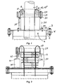
- the Fig. 1 shows a sectional view of the permanent interceptor and Fig. 2 a sectional view of a temporary interceptor.
- the properties and function of the interceptor will be described below using the example of a power cable. In this case, further existing structural elements of the power cable, such as cable wires or cable sheath are not described in detail.
- the power cable for example a 3-core submarine cable 5
- the power cable is 'touched' on the (exposed) armor 6 (on the armor wires) by means of a puller head (not shown and unspecified) and from below through the opening of the platform up onto the horizontal platform 2 pulled and held.
- the power cable may be routed below the opening in a vertical tube.
- a base plate 3 is screwed, which contains 30 prepared holes 4 'for further attachment of the support elements.
- a circular bore 4 for the passage of the power cable.
- a temporary clamping device 50 is attached (see Fig. 2 ).
- This consists according to Fig. 2 of three pairs of half-shells 51, which are wrapped around the cable in the area of the exposed reinforcement and fixed to bolting flanges.
- the half shells have a larger outer diameter than the bore 4 in the base plate 3, so that upon relief of the held cable, the temporary formed from the half shells Clamping device can be placed on the base plate. The load on the pulling head can then be absorbed by the temporary clamping device 50.
- this temporary interception is intended to be temporary because sustained pressure during operation of the cable which catches the load of the suspended power cable can result in irreversible damage to the sheath, insulation and conductors of the power cable.
- the reinforcing wires 6 released by the pulling head are shortened to a suitable length.
- the core ring 10 which is made up of three segments 10 '", is placed just above the temporary clamping device around the cable 10.
- the core ring 10 has a slightly larger inside diameter than the cable in its area, no load or clamping on the cable takes place Now bent over the elliptical cross section of the core ring so far that the ends of the wires again point to the cable surface.
- the armouring wires are so far plastically deformable that they are bent all around the core ring (with an angle of more than 180 °) and there without further holding means take their position.
- a suitable number of hydraulic jacks for example, three jacks 60 with a lifting capacity of about 10 tons
- a suitable number of hydraulic jacks for example, three jacks 60 with a lifting capacity of about 10 tons
- Fixierchulen 30 are mounted from below under the outer ring 20.
- the outer ring has holes which serve the screw connection with the head-side bottles 33 of Fixierchulen.
- the hydraulic lifters are lowered, so that the screw holes on the foot parts 34 of the Fixierchulen 30 come to rest on matching holes in the base plate 3. In this position, the fixing columns 30 are screwed to the base plate 3.
- Fixierchulen 30 may be provided, if not to be expected with large lateral forces. In the event that higher lateral forces are to be expected, the installation of Fixieräulen can be supplemented with other plates (or shells), which are arranged between the Fixierchulen. This leads in cross section to a honeycomb structure, which can then absorb high lateral forces. However, you can also from the outset, instead of the illustrated Fixierchulen large, cylindrical shaped fixing plates 51 used to avoid subsequent reinforcement by other elements.
- the load of the hanging cable takes over the core ring 10 via the Arm michsdrähte 6, via the outer ring 20 and passes over the Fixierklalen 30.
- the introduction of force opens on the base plate 3, or on the platform 2.
- the hydraulic lifts can be removed.
- a protective cover can be provided, which can be placed on the assembly.
- the FIG. 3 shows the outer ring in section and supervision.
- the outer ring 20 consists of three equal segments, each comprising a circular sector of 120 °.
- bores 25 for screw mounting with the support means (on the head flange of Fixierciclen).
- the Fig. 3 still shows the angle W.
- the conical (conical) expansion preferably has an angle of 10 °.
- the cone angle is twice the angle W, namely the angle lying between the generatrices of the cone.
- the FIG. 4 shows the core ring in section and top view.
- the core ring 10 is like the outer ring divided into three parts.
- the core ring 10 is constructed in two parts with respect to its ring plane.
- the torus consists of three identical ring segments.
- Below the ring plane are three Unterlegsegmente (Schschraub comprise 11), which can be screwed to the Toruselementen.
- the core ring diameter 12 is larger than the inner diameter 22 of the outer ring. The core ring can not slip through the outer ring.
- Fixierchulen 30 have each head-side 33 and foot-side flanges 34 for screwing to the base plate or with the platform.
- the advantage of the small number of items comes into play, as well as the fact that the core ring is inserted without fasteners in the outer ring.
- the power cable 5 is 'handled' by means of a pulling head and raised and held upwards.
- the clamping between the core ring 10 and outer ring 20 loosens and dissolves.
- the fixing elements 30 and 51 can be removed.
- the weight of the power cable can be resumed on the now exposed Arm istsdrähten 6.
- all surfaces of the interception device can be treated protected against corrosion.
Abstract
Description
Die Erfindung betrifft eine Abfangvorrichtung für einen von unten durch eine Öffnung einer waagerechten Plattform hindurchgeführten, mit einer Armierungsschicht ausgebildeten, frei hängenden Gegenstand, insbesondere für ein Starkstromkabel.The invention relates to an interceptor for a guided through the bottom of an opening of a horizontal platform, formed with a reinforcing layer, free-hanging object, in particular for a power cable.
Zur temporären Sicherung eines Starkstromkabels bei der Installation oder bei ServiceArbeiten auf einer Plattform (insbesondere an einer Plattform auf See) wird ein Ziehkopf eingesetzt, der an der Armierungsschicht des Starkstromkabels angreift und das Gewicht des hängenden Kabels aufnimmt. Die mechanischen Zugkräfte werden von der Armierungsschicht aufgenommen, wobei möglichst wenig Kräfte auf die innere Kabelstruktur übermittelt werden. Um mögliche mechanische Beanspruchung auf die Kabelstruktur während des Service-Aufenthalts abzufangen, wird das Starkstromkabel mittels einer temporären oder einer permanenten Kabelabfangvorrichtung (englisch 'hang-off') fixiert.To temporarily secure a power cable during installation or servicing work on a platform (especially on a platform at sea), a puller head is used to engage the armor layer of the power cable and pick up the weight of the hanging cable. The mechanical tensile forces are absorbed by the reinforcing layer, with as few forces as possible being transmitted to the inner cable structure. To intercept possible mechanical stress on the cable structure during service, the power cable is fixed by means of a temporary or a permanent cable-catching device (English 'hang-off').
Die
Die Schrift
In einer bekannten Anordnung werden die Armierungsdrähte konisch aufgeweitet und über einen Ring umgebogen. Das Umbiegen erfolgt von dem größeren Durchmesser der Aufweitung nach innen hin in Richtung auf die Kabeloberfläche. Die Armierungsdrähte werden schließlich zwischen zwei jeweils konisch und zueinander passenden Klemmmitteln und einer Deckplatte permanent verklemmt und damit das Kabel mechanisch gesichert (
Eng das Kabel umfassende und in der Regel aus Stahl bestehende Klemm- und Abfangmittel liefern den Nachteil, dass im Betrieb des Kabels Magnetverluste auftreten, die zu Leistungsverlusten und zur thermischen Belastung des Kabels im Bereich der Abfangung führen. Es sind Abdichtungsanordnungen veröffentlicht für den Übergang eines Elektrokabels in ein unter Wasser gelegenes Apparategehäuse. Ein erstes Beispiel zeigt die
Das Lösen der Abfangung, bzw. die Demontage des Elektrokabels in den letztgenannten Anordnungen ist äußerst umständlich, wenn überhaupt nur schwer möglich. In den Anordnungen sind die Armierungselemente von der Innenfläche eines Kernrings kommend zur Außenfläche des Kernrings um den Kernring herumgelegt.The release of the interception, or the disassembly of the electric cable in the latter arrangements is extremely cumbersome, if difficult at all possible. In the arrangements, the reinforcing elements are wrapped around the core ring from the inner surface of a core ring to the outer surface of the core ring.
Werden die Armierungsdrähte am Ort des Eintritts in die Abfangvorrichtung geklemmt, kommt es bei der Klemmung der Drähte zur Verformung des Drahtgefüges und zur Querschnittsverringerung; es tritt dort eine Zugspannungsspitze auf. Die klemmende Aufnahme der Armierungsdrähte unmittelbar am Ort des Eintritts in die Abfangvorrichtung ist eine Schwachstelle und stellt bei derartigen Anordnungen einen Nachteil dar.If the reinforcing wires are clamped in place at the point of entry into the intercepting device, the wires are clamped and the wire structure is deformed and reduced in cross-section; There occurs a tensile stress peak. The clamping reception of Armierungsdrähte immediately at the point of entry into the interceptor is a weak point and is a disadvantage in such arrangements.
Der Erfindung liegt die Aufgabe zugrunde, eine Abfangvorrichtung anzugeben, die einfach zu montieren und zu demontieren ist und bei der die Armierungselemente möglichst schonend verspannt werden.The invention has for its object to provide an interception device that is easy to assemble and disassemble and in which the reinforcing elements are braced as gently as possible.
Ausgehend von bekannten Abfangvorrichtungen wird die Aufgabe erfindungsgemäß durch die Merkmale des unabhängigen Anspruches gelöst, während den abhängigen Ansprüchen vorteilhafte Weiterbildungen der Erfindung zu entnehmen sind.Starting from known interceptors, the object is achieved by the features of the independent claim, while the dependent claims advantageous developments of the invention can be found.
Der Kern der Erfindung ist, dass die Abfangvorrichtung nur aus wenigen Einzelteilen besteht, von denen ein Außenring und Abstützmittel mit der Plattform mittelbar oder unmittelbar fest verbunden sind, und ein von Armierungsdrähten umschlungener Kern- oder Innenring allein in Zugrichtung des langgestreckten Gegenstandes in dem Außenring liegend in selbsttätigen Klemmkontakt und in Haltefunktion der Armierungsdrähte mit dem Außenring steht.The essence of the invention is that the interceptor consists of only a few individual parts, of which an outer ring and support means are connected directly or indirectly fixedly to the platform, and a core or inner ring wrapped by Armierungsdrähten lying alone in the pulling direction of the elongated object in the outer ring in automatic clamping contact and holding function of Armierungsdrähte with the outer ring is.
Zur Aufbringung der Klemmkräfte werden keine Schrauben oder ähnliches eingesetzt, die über Werkzeuge angezogen werden müssen. Der Kernring liegt lose im Außenring ohne weitere Befestigungsmittel. Abfangen, Halten und Klemmen des langgestreckten Gegenstandes kommt bei der Erfindung zuglastabhängig zustande, wenn der langgestreckte Gegenstand freihängend mit seinem Gewicht die Anordnung und die starr mit der Plattform verbundenen Teile beaufschlagt.To apply the clamping forces no screws or the like are used, which must be tightened by tools. The core ring is loose in the outer ring without further fasteners. Interception, holding and clamping of the elongate article is in the invention depending on glass depending on when the elongate object freely suspended with its weight, the arrangement and the rigidly connected to the platform parts.
Zur Montage eines langgestreckten Gegenstandes wird das Eigengewicht des Gegenstandes von einem (temporären) Haltemittel aufgenommen. Hierbei wird der Gegenstande von unten durch eine Öffnung der Plattform nach oben gezogen und gehalten. Die Armierungsdrähte werden um den Kernring herumgelegt und nach Freigabe des Haltemittels vom Außenring klemmend aufgenommen. Bei der Klemmung geht die volle Zuglast vom Haltemittel auf die Abfangvorrichtung über. Durch die Zugkraft des frei hängenden Gegenstandes werden Kernring und Außenring aufeinander gedrückt. Die Klemmung ist damit zugkraftabhängig.For mounting an elongate object, the weight of the object is absorbed by a (temporary) holding means. Here, the article is pulled from below through an opening of the platform up and held. The reinforcing wires are wrapped around the core ring and received by releasing the holding means from the outer ring by clamping. When clamping the full tensile load from the holding means on the interceptor over. Due to the tensile force of the free-hanging object core ring and outer ring are pressed together. The clamping is thus zugkraftabhängig.
Zur Demontage eines wird das von der Abfangvorrichtung aufgenommene Gewicht des langgestreckten Gegenstandes von einer (temporären) Einrichtung übernommen und damit die Abfangvorrichtung vom vollen Gewicht entlastet. Die Zuglast ist praktisch Null, wodurch sich die Klemmung zwischen Kernring und Außenring löst. Die Fixierelemente der Abfangvorrichtung können entfernt werden. Das Gewicht des Gegenstandes kann an den nun freiliegenden Armierungsdrähten aufgenommen werden.To disassemble one, the weight of the elongated object received by the intercepting device is taken over by a (temporary) device, thus relieving the intercepting device of its full weight. The tensile load is practically zero, whereby the clamping between the core ring and outer ring dissolves. The fixing elements of the interceptor can be removed. The weight of the article can be picked up on the now exposed armor wires.
Das System passt sich wechselnden Lastbedingungen automatisch an. Die Klemmung ist zuglastabhängig. Der Außenring liegt über die Abstützmittel (Fixiersäulen) in seiner Position fest. Je mehr sich die Zuglast an den Armierungsdrähten erhöht, desto mehr drückt (klemmt) der Kernring die Armierung gegen die Konusinnenfläche des Außenringes und somit erhöht sich die Haltekraft. Sobald die Zuglast gleich bleibt, bleibt auch die Haltekraft gleich. Eine Vorschädigung der Armierungsdrähte durch Aufbringung der Klemmkräfte über Werkzeuge ist ausgeschlossen.The system automatically adapts to changing load conditions. The clamping is dependent on the glass. The outer ring is fixed on the support means (Fixiersäulen) in its position. The more the tensile load on the reinforcing wires increases, the more the core ring presses (clamps) the reinforcement against the inner cone surface of the outer ring and thus increases the holding force. As soon as the tensile load remains the same, the holding force remains the same. A pre-damage to the reinforcing wires by applying the clamping forces via tools is excluded.
Die Abfangvorrichtung wird für einen von unten durch eine Öffnung einer waagerechten Plattform hindurchgeführten, mit einer Armierungsschicht ausgebildeten langgestreckten Gegenstand vorgeschlagen. Der Gegenstand entwickelt seine Zugkraft durch Eigengewicht senkrecht zur Plattform. Die Abfangvorrichtung umfasst Klemmmittel für die Armierungsschicht und Abstützmittel zum Abstützen der Abfangvorrichtung auf der Plattform. Die Klemmmittel umfassen einen in Umschlingung von Elementen der Armierungsschicht aufnehmenden, den Gegenstand umgebenden Kernring, welcher der Armierungsschicht anliegt, und weiter einen mit der Plattform über Abstützmittel fest verbundenen, den Gegenstand umgebenden Außenring. Der Kernring ist in Zugrichtung des Gegenstandes vom Außenring aufgenommen.The interceptor is proposed for an elongate object formed from below through an opening of a horizontal platform and formed with a reinforcing layer. The object develops its traction by its own weight perpendicular to the platform. The interceptor comprises armor layer clamping means and support means for supporting the interceptor on the platform. The clamping means comprise a core ring, which surrounds the article and is surrounded by elements of the reinforcing layer, which abuts the reinforcing layer, and further connected to the platform via supporting means firmly connected, surrounding the object outer ring. The core ring is received in the pulling direction of the object from the outer ring.
Die Abfangvorrichtung kann mit bevorzugten Ausgestaltungen ausgebildet sein. Die im folgenden genannten Merkmale der Erfindung können einzeln oder gemeinsam auch in verschiedenen Weiterbildungen eingesetzt sein.The interceptor may be formed with preferred embodiments. The features of the invention mentioned below may be used individually or together in various developments.
Die Ausbildung des Kernrings als Torus, vorzugsweise mit elliptischem Querschnitt ist wesentlich. Die Zuglast (Energie) der Armierungsdrähte baut über die ungleichmäßige Form des Kernringquerschnitts (Kraftabbaukurve durch variierende Krümmungsradien auf dem Kernring) bereits einen Teil seiner Zuglast ab. Die Armierung versucht ihre fixierte Form, von einem großen Krümmungsradius zu einem kleinen Krümmungsradius und wiederum auf einen großen Krümmungsradius zu ändern. Dieses kostet Energie, die der Klemmstelle abzurechnen ist.The formation of the core ring as a torus, preferably with elliptical cross-section is essential. The tensile load (energy) of the Armierungsdrähte already on the uneven shape of the core ring cross-section (force reduction curve by varying radii of curvature on the core ring) from a part of its tensile load. The reinforcement attempts to change its fixed shape from a large radius of curvature to a small radius of curvature and again to a large radius of curvature. This costs energy, which must be charged to the nip.
Die Innenfläche des Außenrings ist derart ausgebildet, dass der Kernring in Zugrichtung des Gegenstandes in den Außenring einlegbar ist. Das Größtmaß des Kernringdurchmessers ist größer als das Kleinstmaß des Innendurchmessers des Außenrings. Der Kernring kann durch den Außenring nicht hindurchrutschen.The inner surface of the outer ring is formed such that the core ring in the pulling direction of the article in the outer ring can be inserted. The largest dimension of the core ring diameter is greater than the smallest dimension of the inner diameter of the outer ring. The core ring can not slip through the outer ring.
Der Kernring liegt als Torus vor, wodurch seine Außenfläche konvex ausgebildet ist. Insbesondere kann der Torus einen elliptischen Querschnitt aufweisen, wobei die Hauptachse der Ellipse parallel zur Achse des Gegenstands liegt. Als günstiges Verhältnis von Hauptachse der Ellipse zu Nebenachse der Ellipse kann eine Relation zwischen 1,5 : 1 und 2 : 1 gewählt werden, beispielsweise ein Verhältnis von 1,7 : 1. Die Oberfläche des Kernrings kann mit Riefen oder Rillen versehen sein, so dass es zu einer vergrößerten Haftreibung zwischen Armierungsdrähten und Kernring kommt.The core ring is present as a torus, whereby its outer surface is convex. In particular, the torus may have an elliptical cross-section with the major axis of the ellipse being parallel to the axis of the article. As a favorable ratio of the major axis of the ellipse to the minor axis of the ellipse, a relation between 1.5: 1 and 2: 1 can be selected, for example a ratio of 1.7: 1. The surface of the core ring can be provided with grooves or grooves that there is an increased stiction between Armierungsdrähten and core ring.
Die aus der Armierungsschicht freigelegten Armierungselemente sind über den Kernring herübergelegt und entgegen ihrer ursprünglichen Ausrichtung zurückgelegt. Die Umschlingung der Armierungselemente um den Kernring beträgt mehr als 180°. Die Armierungselemente kommen zwischen einer Außenfläche des Kernrings und einer Innenfläche des Außenrings zu liegen. Die Klemmung entsteht nach Freigabe des temporär getragenen Gegenstands und ist somit zugkraftabhängig.The reinforcing elements exposed from the reinforcing layer are laid over the core ring and returned against their original orientation. The wrapping of the reinforcing elements around the core ring is more than 180 °. The reinforcing elements come to lie between an outer surface of the core ring and an inner surface of the outer ring. The clamping arises after release of the temporarily carried object and is thus zugkraftabhängig.
Die Innenfläche des Außenrings sollte schalenartig zu Aufnahme des Kernrings ausgebildet sein, wobei bevorzugt die Innenfläche des Außenrings sich konisch erweiternd in Richtung auf das oberhalb der Plattform befindliche Ende des Gegenstandes ausgebildet ist. Die konische Aufweitung sollte in einem Winkelbereich von 6° bis 12° liegen. Hierbei ist der zwischen den Mantellinien des Konus liegende halbe Winkel gemeint.The inner surface of the outer ring should be formed like a shell for receiving the core ring, wherein preferably the inner surface of the outer ring is conically widening in the direction of the located above the platform end of the article is formed. The conical expansion should be within an angular range of 6 ° to 12 °. Here, the lying between the generatrices of the cone half angle is meant.
Der Außenring sollte Bohrungen zur Schraubbefestigung mit den Abstützmitteln aufweisen.The outer ring should have holes for Schraubbefestigung with the support means.
Kernring und Außenring sind aus mindestens zwei gleichen Segment-Elementen gebildet. Die jeweiligen Ringe werden von außen um den langgestreckten Gegenstand herumgelegt, wobei sie nicht als Vollring ausgebildet sein können, sondern aus Teilen des jeweiligen Rings, vorzugsweise nämlich aus identischen Segment-Elementen. Bei einer dreiteiligen Ausbildung der Segment-Elemente umfassen die Elemente jeweils einen Kreissektor von 120°. Die Segment-Elemente des Kernrings bestehen vorzugsweise aus drei Ringelemente mit elliptischem Querschnitt. Diese Ringelemente werden über drei Unterschraubelemente verbunden, wodurch ein voller Ring entsteht, dessen Korpus den elliptischen Querschnitt aufweist, und wobei die Hauptachse der Ellipse parallel zur Achse des langgestreckten Gegenstandes liegt.Core ring and outer ring are formed from at least two identical segment elements. The respective rings are wrapped around the elongated object from the outside, wherein they can not be formed as a solid ring, but from parts of the respective ring, preferably namely identical segment elements. In a three-part design of the segment elements, the elements each comprise a circular sector of 120 °. The segment elements of the core ring preferably consist of three ring elements with an elliptical cross-section. These ring elements are connected by three Unterschraubelemente, whereby a full ring is formed, whose body has the elliptical cross section, and wherein the major axis of the ellipse is parallel to the axis of the elongated object.
Die Segment-Elemente des Außenrings bestehen vorzugsweise aus drei Ringsegmente, die über Flansche gegeneinander verschraubbar sind.The segment elements of the outer ring preferably consist of three ring segments, which are screwed against each other via flanges.
Die Abfangvorrichtung kann unmittelbar im Bereich einer Plattformöffnung auf der Plattform aufgeständert und befestigt sein. Vorzugsweise kann auf der Öffnung der Plattform eine mit einer Bohrung für den Durchtritt des Gegenstandes versehene Grundplatte befestigt sein. Die Grundplatte sollte Bohrungen für die Schraubbefestigung mit den Abstützmitteln aufweisen.The interception device can be raised and secured directly in the region of a platform opening on the platform. Preferably, a base plate provided with a bore for the passage of the article can be fastened on the opening of the platform. The base plate should have holes for the screw fastening with the support means.
Die Abstützmittel können in Form mehrerer Fixiersäulen oder in Form von teilzylindrischen Fixierplatten oder Fixierschalen ausgebildet sein. Die Abstützmittel haben vorzugsweise fußseitig und kopfseitig Bohrungen zur Aufnahme von Schrauben zur Verschraubung mit der Plattform, bzw. mit der Grundplatte und zur Aufnahme von Schrauben zur Verschraubung mit dem Außenring.The support means may be in the form of a plurality of fixing columns or in the form of part-cylindrical fixing plates or fixing shells. The support means preferably have foot side and head side holes for receiving screws for screwing to the platform, or with the base plate and for receiving screws for screwing to the outer ring.
Durch die Klemmung der Armierungsdrähte kommt auch eine leitende Anbindung zum Masse-Potential zustande.By clamping the Armierungsdrähte also comes a conductive connection to the ground potential.
Die vorliegende Erfindung ist nicht auf die vorstehend beschriebenen Ausführungsformen beschränkt, sondern umfasst auch alle im Sinne der Erfindung gleichwirkenden Ausführungsformen. So lässt sich die Erfindung beispielsweise auch für mit Armierungsdrähten verstärkte Rohre oder Pipelines einsetzen. Die Darstellung der Erfindung unter besonderer Betonung einer Kabelabfangvorrichtung soll nicht bedeuten, dass die Abfangvorrichtung nur für die Anwendung auf Starkstromkabel eingeschränkt ist.The present invention is not limited to the embodiments described above, but also includes all the same in the context of the invention embodiments. For example, the invention can also be used for pipes or pipelines reinforced with reinforcing wires. The presentation of the invention with particular emphasis on a cable clamp does not mean that the interceptor is limited only for use on power cables.
Weitere Einzelheiten und Vorteile der Erfindung werden mit einem bevorzugten Ausführungsbeispiel anhand von Figuren erläutert. Sie zeigen im Einzelnen
-
Figur 1 : eine Schnittdarstellung der Abfangvorrichtung; -
Figur 2 : eine Schnittdarstellung einer temporären Abfangvorrichtung; -
Figur 3 : den Außenring; -
Figur 4 : den Kernring und -
Figur 5 : die Abstützmittel.
-
FIG. 1 a sectional view of the interceptor; -
FIG. 2 a sectional view of a temporary interceptor; -
FIG. 3 : the outer ring; -
FIG. 4 : the core ring and -
FIG. 5 : the support means.
Die
Das Starkstromkabel, beispielsweise ein dreiadriges Seekabel 5, wird an der (freigelegten) Armierung 6 (an den Armierungsdrähten) mittels eines (nicht dargestellten und nicht näher beschriebenen) Ziehkopfs 'angefasst' und von unten durch die Öffnung der Plattform nach oben auf die waagerechte Plattform 2 gezogen und so gehalten. Das Starkstromkabel kann unterhalb der Öffnung in einem senkrecht verlaufenden Rohr geführt sein. Am Rand der Öffnung ist eine Grundplatte 3 verschraubt, die zur weiteren Befestigung der Abstützelemente 30 vorbereitete Bohrungen 4' enthält. In der Mitte der Grundplatte 3 befindet sich eine kreisförmige Bohrung 4 für den Durchtritt des Starkstromkabels.The power cable, for example a 3-
In dieser Halteposition wird eine temporäre Klemmvorrichtung 50 angebracht (siehe
Diese temporäre Abfangung soll jedoch nur vorübergehend eingesetzt werden, weil ein Dauerdruck während des Betriebs des Kabels, der die Last des hängenden Starkstromkabels abfängt, zu irreversiblen Schäden im Mantel, an der Isolierung und an den Leitern des Starkstromkabels führen kann.However, this temporary interception is intended to be temporary because sustained pressure during operation of the cable which catches the load of the suspended power cable can result in irreversible damage to the sheath, insulation and conductors of the power cable.
Im nächsten Schritt werden die vom Ziehkopf freigegebenen Armierungsdrähte 6 auf geeignete Länge gekürzt. Der aus drei Segmenten 10'" bestehende Kernring 10 wird kurz oberhalb der temporären Klemmvorrichtung um das Kabel gelegt. Der Kernring 10 hat einen etwas größeren Innendurchmesser als das Kabel im dortigen Bereich, eine Belastung oder Klemmung am Kabel findet nicht statt. Die Armierungsdrähte 6 werden nun über den elliptischen Querschnitt des Kernrings soweit gebogen, dass die Enden der Drähte wieder auf die Kabeloberfläche zeigen. Die Armierungsdrähte sind so weit plastisch verformbar, dass sie ganz um den Kernring (mit einem Winkel von mehr als 180°) herum gebogen werden und dort ohne weitere Haltemittel ihre Lage einnehmen.In the next step, the reinforcing
Nach dieser Vorbereitung wird eine geeignete Zahl von Hydraulikhebern (beispielsweise drei Wagenheber 60 mit Hebeleistung von ca. 10 Tonnen) auf der Grundplatte 3 positioniert. Auf den Hebestempeln 61 wird der Außenring 20 aufgelegt, der wie der Kernring 10 aus drei Segmenten 20'" besteht (vgl.
Durch den Hebevorgang der Hydraulikheber kommt es von unten zur Anlage und zur Klemmung der Innenfläche 22' des Außenrings mit den um den Kernring 10 herumgelegten und auf der konvexen Außenfläche 12' des Kernrings liegenden Armierungsdrähten 6. Das Anheben mittels Hydraulikheber geschieht nur auf einem Weg von wenigen Millimetern Hub, so dass die Last des Starkstromkabels voll von der Klemmung zwischen Außenring 20 und Kernring 10 aufgenommen ist. Die temporäre Klemmvorrichtung ist entlastet 50, übernimmt keine Kräfte und kann somit entfernt werden.By lifting the hydraulic lifter it comes from below for conditioning and clamping the inner surface 22 'of the outer ring with the wrapped around the
Danach werden Abstützelemente in Form von mehreren (beispielsweise sechs) Fixiersäulen 30 von unten unter den Außenring 20 montiert. Der Außenring weist Bohrungen auf, die der Schraubverbindung mit den kopfseitigen Flaschen 33 der Fixiersäulen dienen. Abschließend werden die Hydraulikheber abgesenkt, so dass die Schraublöcher an den Fußteilen 34 der Fixiersäulen 30 auf passende Bohrungen in der Grundplatte 3 zu liegen kommen. In dieser Lage werden die Fixiersäulen 30 mit der Grundplatte 3 verschraubt.Thereafter, support elements in the form of several (for example, six)
Der Einsatz der Fixiersäulen 30 kann vorgesehen sein, wenn nicht mit großen Querkräften zu rechnen ist. Für den Fall, dass höhere Querkräfte zu erwarten sind, kann der Einbau der Fixiersäulen mit weiteren Platten (oder Schalen) ergänzt werden, die zwischen den Fixiersäulen angeordnet sind. Dieses führt im Querschnitt zu einer Wabenstruktur, die dann hohe Querkräfte aufnehmen kann. Man kann jedoch auch von vornherein, statt der dargestellten Fixiersäulen großflächige, zylindrisch geformte Fixierplatten 51 einsetzen, um eine nachträgliche Verstärkung durch weitere Elemente zu vermeiden.The use of
Die Last des hängenden Kabels übernimmt der Kernring 10 über die Armierungsdrähte 6, über den Außenring 20 und geht über auf die Fixiersäulen 30. Die Krafteinleitung mündet auf der Grundplatte 3, bzw. auf der Plattform 2. Der von den Armierungsdrähten 6 umschlungene Kernring 10 klemmt von der Zugkraft des Gegenstandes 5 verursacht, zugkraftabhängig die Armierungsdrähte 6 in der Innenfläche des Außenrings 20.The load of the hanging cable takes over the
Die Hydraulikheber können entfernt werden. Zum Schutz der Kabelabfangvorrichtung kann eine Schutzhaube vorgesehen sein, die auf die Anordnung gelegt werden kann.The hydraulic lifts can be removed. To protect the cable support device, a protective cover can be provided, which can be placed on the assembly.
Die
Die
Mit der
Zur Demontage des Starkstromkabels kommt der Vorteil der geringen Zahl von Einzelteilen ins Spiel, sowie die Tatsache, dass der Kernring ohne Befestigungsmittel in den Außenring eingelegt ist. Ähnlich wie bei der Montage wird das Starkstromkabel 5 mittels eines Ziehkopfs 'angefasst' und nach oben angehoben und gehalten. Die Klemmung zwischen Kernring 10 und Außenring 20 lockert und löst sich. Die Fixierelemente 30 und 51 können entfernt werden. Das Gewicht des Starkstromkabels kann an den nun freiliegenden Armierungsdrähten 6 wieder aufgenommen werden.To disassemble the power cable, the advantage of the small number of items comes into play, as well as the fact that the core ring is inserted without fasteners in the outer ring. Similar to the mounting, the
Vorzugsweise für den Einsatz in Meeresklima oder in anderer korrosiver Umgebung können alle Oberflächen der Abfangvorrichtung korrosionsgeschützt behandelt sein.Preferably, for use in marine environments or in other corrosive environment all surfaces of the interception device can be treated protected against corrosion.
- 22
- Plattformplatform
- 33
- Grundplattebaseplate
- 44
- Öffnung, Bohrung in GrundplatteOpening, hole in base plate
- 4'4 '
- Bohrungen für AbstützmittelHoles for support means
- 55
- Gegenstand, StarkstromkabelObject, power cable
- 66
- Armierungsschicht, ArmierungsdrähteReinforcing layer, reinforcing wires
- 1010
- erster Ring - Kernring mit elliptischem Querschnittfirst ring - core ring with elliptical cross section
- 10'"10 ''
- Aufbau in Form dreier SegmenteConstruction in the form of three segments
- 1111
- UnterlegsegmenteUnterlegsegmente
- 1212
- größter Außendurchmesser; Kernringdurchmesserlargest outer diameter; Core ring diameter
- 12'12 '
- konvexe Außenflächeconvex outer surface
- 1414
- Hauptachse EllipseMain axis ellipse
- 2020
- zweiter Ring - Außenringsecond ring - outer ring
- 20'"20 ''
- Aufbau in Form dreier SegmenteConstruction in the form of three segments
- 2222
- Innenfläche, konisch nach oben sich öffnendInner surface, conically opening upwards
- WW
- Konuswinkelcone angle
- 2525
- Befestigungsschraubefixing screw
- 3030
- Abstützmittel, FixiersäuleSupporting means, fixing column
- 3232
- Schraube am FußendeScrew at the foot
- 3333
- kopfseitiger Flanschhead-side flange
- 3434
- fußseitiger Flanschfoot-side flange
- 5050
- Hilfsklemmmittel, temporäre AbfangungAuxiliary clamp, temporary support
- 5151
- Fixierplatten oder -schalenFixing plates or dishes
- 6060
- Hydraulikheberhydraulic jacks
- 6161
- Hebestempellifting temple
- 6262
- Hubrichtungstroke direction
Claims (10)
dadurch gekennzeichnet, dass die Klemmmittel einen in Umschlingung der Armierungselemente (6) aufnehmenden, den Gegenstand (5) umgebenden Kernring (10),
und einen mit der Plattform (2) über die Abstützmittel (30) fest verbundenen, den Gegenstand (5) umgebenden Außenring (20) umfassen, und hierbei eine Innenfläche (22') des Außenrings (20) hin zur Außenfläche (12') des Kernrings (10) gerichtet ist,
wobei die Armierungselemente (6) von der Innenfläche des Kernrings (10) kommend zur Außenfläche (12') des Kernrings (10) um den Kernring (10) herumgelegt sind,
wobei eine zuglastabhängige Klemmung der Armierungselemente (6) zwischen der Außenfläche (12') des lose in den Außenring (20) eingelegten Kernrings (10) und der Innenfläche (22') des Außenrings (20) allein dadurch erfolgt, dass durch Zugkraft des frei hängenden Gegenstandes (5) Kernring (10) und Außenring (20) aufeinander gedrückt werden.Supporting device for an elongate object (5), which is passed through an opening of a horizontal platform (2) from below and has a reinforcing layer consisting of reinforcing elements (6), wherein the intercepting device comprises clamping means (10, 20) for the reinforcing layer (6) and supporting means ( 30) for supporting the interceptor on the platform,
characterized in that the clamping means comprises a core ring (10) which surrounds the reinforcing elements (6) and surrounds the object (5),
and an outer ring (20) fixedly connected to the platform (2) via the support means (30) and surrounding the article (5), and an inner surface (22 ') of the outer ring (20) towards the outer surface (12') of the Core ring (10) is directed,
wherein the reinforcing elements (6) from the inner surface of the core ring (10) to the outer surface (12 ') of the core ring (10) are wrapped around the core ring (10),
wherein a glazing-dependent clamping of the reinforcing elements (6) between the outer surface (12 ') of the loosely inserted into the outer ring (20) core ring (10) and the inner surface (22') of the outer ring (20) solely by pulling force of the free hanging object (5) core ring (10) and outer ring (20) are pressed against each other.
Applications Claiming Priority (1)
| Application Number | Priority Date | Filing Date | Title |
|---|---|---|---|
| DE201110109328 DE102011109328B3 (en) | 2011-08-03 | 2011-08-03 | Interception device, preferably for power cables |
Publications (3)
| Publication Number | Publication Date |
|---|---|
| EP2555366A2 true EP2555366A2 (en) | 2013-02-06 |
| EP2555366A3 EP2555366A3 (en) | 2014-02-19 |
| EP2555366B1 EP2555366B1 (en) | 2015-07-15 |
Family
ID=46801272
Family Applications (1)
| Application Number | Title | Priority Date | Filing Date |
|---|---|---|---|
| EP12005660.1A Not-in-force EP2555366B1 (en) | 2011-08-03 | 2012-08-03 | Capture device, in particular for high voltage cable |
Country Status (4)
| Country | Link |
|---|---|
| EP (1) | EP2555366B1 (en) |
| DE (1) | DE102011109328B3 (en) |
| DK (1) | DK2555366T3 (en) |
| ES (1) | ES2546875T3 (en) |
Families Citing this family (1)
| Publication number | Priority date | Publication date | Assignee | Title |
|---|---|---|---|---|
| DE202016103896U1 (en) | 2016-07-19 | 2016-10-21 | Ams Gmbh | Fastening device for a line |
Citations (5)
| Publication number | Priority date | Publication date | Assignee | Title |
|---|---|---|---|---|
| DE832009C (en) | 1948-03-22 | 1952-02-18 | Telegraph Constr & Maintenance | Cable sealing |
| DE1042063B (en) | 1957-08-09 | 1958-10-30 | Felten & Guilleaume Carlswerk | Support device for the armouring of electrical cables |
| GB1571679A (en) | 1978-04-13 | 1980-07-16 | Standard Telephones Cables Ltd | Terminating armoured cables |
| US20060193572A1 (en) | 2005-02-11 | 2006-08-31 | Einar Mjelstad | Power umbilical for deep water |
| US20100314151A1 (en) | 2009-06-15 | 2010-12-16 | Peter William Worrall | Cable termination system |
Family Cites Families (4)
| Publication number | Priority date | Publication date | Assignee | Title |
|---|---|---|---|---|
| US3855414A (en) * | 1973-04-24 | 1974-12-17 | Anaconda Co | Cable armor clamp |
| US4259543A (en) * | 1978-02-07 | 1981-03-31 | International Telephone And Telegraph Corporation | Cable termination |
| MY155589A (en) * | 2008-05-30 | 2015-11-13 | Technip France | Power umbilical |
| GB2476655B (en) * | 2009-12-30 | 2014-03-19 | Jdr Cable Systems Ltd | Cable termination system |
-
2011
- 2011-08-03 DE DE201110109328 patent/DE102011109328B3/en not_active Expired - Fee Related
-
2012
- 2012-08-03 DK DK12005660.1T patent/DK2555366T3/en active
- 2012-08-03 EP EP12005660.1A patent/EP2555366B1/en not_active Not-in-force
- 2012-08-03 ES ES12005660.1T patent/ES2546875T3/en active Active
Patent Citations (5)
| Publication number | Priority date | Publication date | Assignee | Title |
|---|---|---|---|---|
| DE832009C (en) | 1948-03-22 | 1952-02-18 | Telegraph Constr & Maintenance | Cable sealing |
| DE1042063B (en) | 1957-08-09 | 1958-10-30 | Felten & Guilleaume Carlswerk | Support device for the armouring of electrical cables |
| GB1571679A (en) | 1978-04-13 | 1980-07-16 | Standard Telephones Cables Ltd | Terminating armoured cables |
| US20060193572A1 (en) | 2005-02-11 | 2006-08-31 | Einar Mjelstad | Power umbilical for deep water |
| US20100314151A1 (en) | 2009-06-15 | 2010-12-16 | Peter William Worrall | Cable termination system |
Also Published As
| Publication number | Publication date |
|---|---|
| ES2546875T3 (en) | 2015-09-29 |
| DE102011109328B3 (en) | 2012-12-27 |
| EP2555366A3 (en) | 2014-02-19 |
| EP2555366B1 (en) | 2015-07-15 |
| DK2555366T3 (en) | 2015-10-05 |
Similar Documents
| Publication | Publication Date | Title |
|---|---|---|
| DE102014108696A1 (en) | Compression of a stator core | |
| EP2541560A1 (en) | Superconductor cable | |
| EP2555366B1 (en) | Capture device, in particular for high voltage cable | |
| DE1047893B (en) | Field spacer for electrical stranded conductors | |
| DE1303660B (en) | ||
| AT506224B1 (en) | STOPPING DEVICE FOR FALLING SAFETY | |
| WO2011069852A1 (en) | Device for electrically conductively connecting main conductors of a high-current cable to branch conductors | |
| EP3975358B1 (en) | Bracket for holding cables, preferably highvoltage cables | |
| EP2546545A2 (en) | Device for fixing a tension element, in particular a pull rope | |
| DE112015004283T5 (en) | LENGTH CHANGE TOOL FOR LIGHTING | |
| EP3217494B1 (en) | Bracket for holding cables, preferably highvoltage cables | |
| EP3113310A1 (en) | Cable end for a cable and method of making same | |
| EP2966224B1 (en) | Spreading device for a bridge rope dressing | |
| DE102017002558A1 (en) | Mast clamp and mast arrangement that can be produced therewith | |
| CN107964950A (en) | Riveted type anchorage cable stretching device and anchor cable two times tensioning device | |
| DE202007015697U1 (en) | Fastening device for a scaffold | |
| CN108086331A (en) | Bonded existing anchorage cable stretching device and existing anchor cable two times tensioning device | |
| DE102020131501B4 (en) | Spacers for pipes | |
| CH363692A (en) | Flexible spacer for overhead lines | |
| DE202016103896U1 (en) | Fastening device for a line | |
| DE102016120717A1 (en) | Armierungsstab from a fiber composite, as well as push cable for transmitting digital signals with a clutch of such reinforcing bars | |
| DE3902477C1 (en) | Outer conductor coupling for coaxial cables | |
| DE10305312A1 (en) | Insulation jacket in the area of the pipe suspension | |
| DE681790C (en) | Cables for mobile telecommunications systems | |
| AT249150B (en) | Support for cable bundles especially laid in telephone exchanges |
Legal Events
| Date | Code | Title | Description |
|---|---|---|---|
| PUAI | Public reference made under article 153(3) epc to a published international application that has entered the european phase |
Free format text: ORIGINAL CODE: 0009012 |
|
| AK | Designated contracting states |
Kind code of ref document: A2 Designated state(s): AL AT BE BG CH CY CZ DE DK EE ES FI FR GB GR HR HU IE IS IT LI LT LU LV MC MK MT NL NO PL PT RO RS SE SI SK SM TR |
|
| AX | Request for extension of the european patent |
Extension state: BA ME |
|
| PUAL | Search report despatched |
Free format text: ORIGINAL CODE: 0009013 |
|
| AK | Designated contracting states |
Kind code of ref document: A3 Designated state(s): AL AT BE BG CH CY CZ DE DK EE ES FI FR GB GR HR HU IE IS IT LI LT LU LV MC MK MT NL NO PL PT RO RS SE SI SK SM TR |
|
| AX | Request for extension of the european patent |
Extension state: BA ME |
|
| RIC1 | Information provided on ipc code assigned before grant |
Ipc: H02G 15/06 20060101ALI20140116BHEP Ipc: H02G 15/14 20060101ALI20140116BHEP Ipc: H02G 9/12 20060101AFI20140116BHEP |
|
| 17P | Request for examination filed |
Effective date: 20140331 |
|
| RBV | Designated contracting states (corrected) |
Designated state(s): AL AT BE BG CH CY CZ DE DK EE ES FI FR GB GR HR HU IE IS IT LI LT LU LV MC MK MT NL NO PL PT RO RS SE SI SK SM TR |
|
| RAP1 | Party data changed (applicant data changed or rights of an application transferred) |
Owner name: NKT CABLES GMBH & CO. KG |
|
| GRAP | Despatch of communication of intention to grant a patent |
Free format text: ORIGINAL CODE: EPIDOSNIGR1 |
|
| INTG | Intention to grant announced |
Effective date: 20150212 |
|
| GRAS | Grant fee paid |
Free format text: ORIGINAL CODE: EPIDOSNIGR3 |
|
| GRAA | (expected) grant |
Free format text: ORIGINAL CODE: 0009210 |
|
| AK | Designated contracting states |
Kind code of ref document: B1 Designated state(s): AL AT BE BG CH CY CZ DE DK EE ES FI FR GB GR HR HU IE IS IT LI LT LU LV MC MK MT NL NO PL PT RO RS SE SI SK SM TR |
|
| REG | Reference to a national code |
Ref country code: CH Ref legal event code: EP Ref country code: GB Ref legal event code: FG4D Free format text: NOT ENGLISH |
|
| REG | Reference to a national code |
Ref country code: IE Ref legal event code: FG4D Free format text: LANGUAGE OF EP DOCUMENT: GERMAN |
|
| REG | Reference to a national code |
Ref country code: AT Ref legal event code: REF Ref document number: 737209 Country of ref document: AT Kind code of ref document: T Effective date: 20150815 |
|
| REG | Reference to a national code |
Ref country code: DE Ref legal event code: R096 Ref document number: 502012003773 Country of ref document: DE |
|
| REG | Reference to a national code |
Ref country code: ES Ref legal event code: FG2A Ref document number: 2546875 Country of ref document: ES Kind code of ref document: T3 Effective date: 20150929 |
|
| REG | Reference to a national code |
Ref country code: DK Ref legal event code: T3 Effective date: 20150929 |
|
| REG | Reference to a national code |
Ref country code: SE Ref legal event code: TRGR |
|
| REG | Reference to a national code |
Ref country code: NL Ref legal event code: FP |
|
| REG | Reference to a national code |
Ref country code: NO Ref legal event code: T2 Effective date: 20150715 |
|
| REG | Reference to a national code |
Ref country code: LT Ref legal event code: MG4D |
|
| PG25 | Lapsed in a contracting state [announced via postgrant information from national office to epo] |
Ref country code: FI Free format text: LAPSE BECAUSE OF FAILURE TO SUBMIT A TRANSLATION OF THE DESCRIPTION OR TO PAY THE FEE WITHIN THE PRESCRIBED TIME-LIMIT Effective date: 20150715 Ref country code: GR Free format text: LAPSE BECAUSE OF FAILURE TO SUBMIT A TRANSLATION OF THE DESCRIPTION OR TO PAY THE FEE WITHIN THE PRESCRIBED TIME-LIMIT Effective date: 20151016 Ref country code: LT Free format text: LAPSE BECAUSE OF FAILURE TO SUBMIT A TRANSLATION OF THE DESCRIPTION OR TO PAY THE FEE WITHIN THE PRESCRIBED TIME-LIMIT Effective date: 20150715 Ref country code: LV Free format text: LAPSE BECAUSE OF FAILURE TO SUBMIT A TRANSLATION OF THE DESCRIPTION OR TO PAY THE FEE WITHIN THE PRESCRIBED TIME-LIMIT Effective date: 20150715 |
|
| PG25 | Lapsed in a contracting state [announced via postgrant information from national office to epo] |
Ref country code: PL Free format text: LAPSE BECAUSE OF FAILURE TO SUBMIT A TRANSLATION OF THE DESCRIPTION OR TO PAY THE FEE WITHIN THE PRESCRIBED TIME-LIMIT Effective date: 20150715 Ref country code: HR Free format text: LAPSE BECAUSE OF FAILURE TO SUBMIT A TRANSLATION OF THE DESCRIPTION OR TO PAY THE FEE WITHIN THE PRESCRIBED TIME-LIMIT Effective date: 20150715 Ref country code: RS Free format text: LAPSE BECAUSE OF FAILURE TO SUBMIT A TRANSLATION OF THE DESCRIPTION OR TO PAY THE FEE WITHIN THE PRESCRIBED TIME-LIMIT Effective date: 20150715 Ref country code: PT Free format text: LAPSE BECAUSE OF FAILURE TO SUBMIT A TRANSLATION OF THE DESCRIPTION OR TO PAY THE FEE WITHIN THE PRESCRIBED TIME-LIMIT Effective date: 20151116 |
|
| REG | Reference to a national code |
Ref country code: CH Ref legal event code: PL |
|
| REG | Reference to a national code |
Ref country code: DE Ref legal event code: R097 Ref document number: 502012003773 Country of ref document: DE |
|
| PG25 | Lapsed in a contracting state [announced via postgrant information from national office to epo] |
Ref country code: CZ Free format text: LAPSE BECAUSE OF FAILURE TO SUBMIT A TRANSLATION OF THE DESCRIPTION OR TO PAY THE FEE WITHIN THE PRESCRIBED TIME-LIMIT Effective date: 20150715 Ref country code: CH Free format text: LAPSE BECAUSE OF NON-PAYMENT OF DUE FEES Effective date: 20150831 Ref country code: LI Free format text: LAPSE BECAUSE OF NON-PAYMENT OF DUE FEES Effective date: 20150831 Ref country code: MC Free format text: LAPSE BECAUSE OF FAILURE TO SUBMIT A TRANSLATION OF THE DESCRIPTION OR TO PAY THE FEE WITHIN THE PRESCRIBED TIME-LIMIT Effective date: 20150715 Ref country code: SK Free format text: LAPSE BECAUSE OF FAILURE TO SUBMIT A TRANSLATION OF THE DESCRIPTION OR TO PAY THE FEE WITHIN THE PRESCRIBED TIME-LIMIT Effective date: 20150715 Ref country code: EE Free format text: LAPSE BECAUSE OF FAILURE TO SUBMIT A TRANSLATION OF THE DESCRIPTION OR TO PAY THE FEE WITHIN THE PRESCRIBED TIME-LIMIT Effective date: 20150715 Ref country code: IT Free format text: LAPSE BECAUSE OF FAILURE TO SUBMIT A TRANSLATION OF THE DESCRIPTION OR TO PAY THE FEE WITHIN THE PRESCRIBED TIME-LIMIT Effective date: 20150715 |
|
| PLBE | No opposition filed within time limit |
Free format text: ORIGINAL CODE: 0009261 |
|
| STAA | Information on the status of an ep patent application or granted ep patent |
Free format text: STATUS: NO OPPOSITION FILED WITHIN TIME LIMIT |
|
| PG25 | Lapsed in a contracting state [announced via postgrant information from national office to epo] |
Ref country code: RO Free format text: LAPSE BECAUSE OF FAILURE TO SUBMIT A TRANSLATION OF THE DESCRIPTION OR TO PAY THE FEE WITHIN THE PRESCRIBED TIME-LIMIT Effective date: 20150715 |
|
| REG | Reference to a national code |
Ref country code: IE Ref legal event code: MM4A |
|
| 26N | No opposition filed |
Effective date: 20160418 |
|
| PG25 | Lapsed in a contracting state [announced via postgrant information from national office to epo] |
Ref country code: IS Free format text: LAPSE BECAUSE OF FAILURE TO SUBMIT A TRANSLATION OF THE DESCRIPTION OR TO PAY THE FEE WITHIN THE PRESCRIBED TIME-LIMIT Effective date: 20150715 |
|
| PG25 | Lapsed in a contracting state [announced via postgrant information from national office to epo] |
Ref country code: IE Free format text: LAPSE BECAUSE OF NON-PAYMENT OF DUE FEES Effective date: 20150803 |
|
| REG | Reference to a national code |
Ref country code: FR Ref legal event code: PLFP Year of fee payment: 5 |
|
| PG25 | Lapsed in a contracting state [announced via postgrant information from national office to epo] |
Ref country code: SI Free format text: LAPSE BECAUSE OF FAILURE TO SUBMIT A TRANSLATION OF THE DESCRIPTION OR TO PAY THE FEE WITHIN THE PRESCRIBED TIME-LIMIT Effective date: 20150715 |
|
| PG25 | Lapsed in a contracting state [announced via postgrant information from national office to epo] |
Ref country code: MT Free format text: LAPSE BECAUSE OF FAILURE TO SUBMIT A TRANSLATION OF THE DESCRIPTION OR TO PAY THE FEE WITHIN THE PRESCRIBED TIME-LIMIT Effective date: 20150715 |
|
| PG25 | Lapsed in a contracting state [announced via postgrant information from national office to epo] |
Ref country code: BG Free format text: LAPSE BECAUSE OF FAILURE TO SUBMIT A TRANSLATION OF THE DESCRIPTION OR TO PAY THE FEE WITHIN THE PRESCRIBED TIME-LIMIT Effective date: 20150715 Ref country code: HU Free format text: LAPSE BECAUSE OF FAILURE TO SUBMIT A TRANSLATION OF THE DESCRIPTION OR TO PAY THE FEE WITHIN THE PRESCRIBED TIME-LIMIT; INVALID AB INITIO Effective date: 20120803 Ref country code: SM Free format text: LAPSE BECAUSE OF FAILURE TO SUBMIT A TRANSLATION OF THE DESCRIPTION OR TO PAY THE FEE WITHIN THE PRESCRIBED TIME-LIMIT Effective date: 20150715 |
|
| PG25 | Lapsed in a contracting state [announced via postgrant information from national office to epo] |
Ref country code: CY Free format text: LAPSE BECAUSE OF FAILURE TO SUBMIT A TRANSLATION OF THE DESCRIPTION OR TO PAY THE FEE WITHIN THE PRESCRIBED TIME-LIMIT Effective date: 20150715 |
|
| REG | Reference to a national code |
Ref country code: FR Ref legal event code: PLFP Year of fee payment: 6 |
|
| PG25 | Lapsed in a contracting state [announced via postgrant information from national office to epo] |
Ref country code: TR Free format text: LAPSE BECAUSE OF FAILURE TO SUBMIT A TRANSLATION OF THE DESCRIPTION OR TO PAY THE FEE WITHIN THE PRESCRIBED TIME-LIMIT Effective date: 20150715 |
|
| PG25 | Lapsed in a contracting state [announced via postgrant information from national office to epo] |
Ref country code: LU Free format text: LAPSE BECAUSE OF NON-PAYMENT OF DUE FEES Effective date: 20150803 |
|
| PG25 | Lapsed in a contracting state [announced via postgrant information from national office to epo] |
Ref country code: MK Free format text: LAPSE BECAUSE OF FAILURE TO SUBMIT A TRANSLATION OF THE DESCRIPTION OR TO PAY THE FEE WITHIN THE PRESCRIBED TIME-LIMIT Effective date: 20150715 |
|
| REG | Reference to a national code |
Ref country code: FR Ref legal event code: PLFP Year of fee payment: 7 |
|
| REG | Reference to a national code |
Ref country code: AT Ref legal event code: MM01 Ref document number: 737209 Country of ref document: AT Kind code of ref document: T Effective date: 20170803 |
|
| PG25 | Lapsed in a contracting state [announced via postgrant information from national office to epo] |
Ref country code: AL Free format text: LAPSE BECAUSE OF FAILURE TO SUBMIT A TRANSLATION OF THE DESCRIPTION OR TO PAY THE FEE WITHIN THE PRESCRIBED TIME-LIMIT Effective date: 20150715 |
|
| PG25 | Lapsed in a contracting state [announced via postgrant information from national office to epo] |
Ref country code: AT Free format text: LAPSE BECAUSE OF NON-PAYMENT OF DUE FEES Effective date: 20170803 |
|
| PGFP | Annual fee paid to national office [announced via postgrant information from national office to epo] |
Ref country code: NL Payment date: 20190819 Year of fee payment: 8 |
|
| PGFP | Annual fee paid to national office [announced via postgrant information from national office to epo] |
Ref country code: SE Payment date: 20190816 Year of fee payment: 8 Ref country code: DE Payment date: 20190819 Year of fee payment: 8 Ref country code: FR Payment date: 20190815 Year of fee payment: 8 Ref country code: ES Payment date: 20190906 Year of fee payment: 8 Ref country code: DK Payment date: 20190816 Year of fee payment: 8 Ref country code: NO Payment date: 20190821 Year of fee payment: 8 |
|
| PGFP | Annual fee paid to national office [announced via postgrant information from national office to epo] |
Ref country code: BE Payment date: 20190819 Year of fee payment: 8 |
|
| PGFP | Annual fee paid to national office [announced via postgrant information from national office to epo] |
Ref country code: GB Payment date: 20190816 Year of fee payment: 8 |
|
| REG | Reference to a national code |
Ref country code: DE Ref legal event code: R119 Ref document number: 502012003773 Country of ref document: DE |
|
| REG | Reference to a national code |
Ref country code: NO Ref legal event code: MMEP |
|
| REG | Reference to a national code |
Ref country code: DK Ref legal event code: EBP Effective date: 20200831 |
|
| REG | Reference to a national code |
Ref country code: SE Ref legal event code: EUG |
|
| REG | Reference to a national code |
Ref country code: NL Ref legal event code: MM Effective date: 20200901 |
|
| GBPC | Gb: european patent ceased through non-payment of renewal fee |
Effective date: 20200803 |
|
| PG25 | Lapsed in a contracting state [announced via postgrant information from national office to epo] |
Ref country code: NO Free format text: LAPSE BECAUSE OF NON-PAYMENT OF DUE FEES Effective date: 20200831 |
|
| REG | Reference to a national code |
Ref country code: BE Ref legal event code: MM Effective date: 20200831 |
|
| PG25 | Lapsed in a contracting state [announced via postgrant information from national office to epo] |
Ref country code: SE Free format text: LAPSE BECAUSE OF NON-PAYMENT OF DUE FEES Effective date: 20200804 |
|
| PG25 | Lapsed in a contracting state [announced via postgrant information from national office to epo] |
Ref country code: DE Free format text: LAPSE BECAUSE OF NON-PAYMENT OF DUE FEES Effective date: 20210302 Ref country code: FR Free format text: LAPSE BECAUSE OF NON-PAYMENT OF DUE FEES Effective date: 20200831 |
|
| PG25 | Lapsed in a contracting state [announced via postgrant information from national office to epo] |
Ref country code: GB Free format text: LAPSE BECAUSE OF NON-PAYMENT OF DUE FEES Effective date: 20200803 Ref country code: BE Free format text: LAPSE BECAUSE OF NON-PAYMENT OF DUE FEES Effective date: 20200831 Ref country code: DK Free format text: LAPSE BECAUSE OF NON-PAYMENT OF DUE FEES Effective date: 20200831 |
|
| PG25 | Lapsed in a contracting state [announced via postgrant information from national office to epo] |
Ref country code: NL Free format text: LAPSE BECAUSE OF NON-PAYMENT OF DUE FEES Effective date: 20200901 |
|
| REG | Reference to a national code |
Ref country code: ES Ref legal event code: FD2A Effective date: 20220110 |
|
| PG25 | Lapsed in a contracting state [announced via postgrant information from national office to epo] |
Ref country code: ES Free format text: LAPSE BECAUSE OF NON-PAYMENT OF DUE FEES Effective date: 20200804 |