EP2555337A1 - Waterproof connector - Google Patents
Waterproof connector Download PDFInfo
- Publication number
- EP2555337A1 EP2555337A1 EP11765649A EP11765649A EP2555337A1 EP 2555337 A1 EP2555337 A1 EP 2555337A1 EP 11765649 A EP11765649 A EP 11765649A EP 11765649 A EP11765649 A EP 11765649A EP 2555337 A1 EP2555337 A1 EP 2555337A1
- Authority
- EP
- European Patent Office
- Prior art keywords
- retainers
- receiving portion
- waterproof connector
- seal
- seal member
- Prior art date
- Legal status (The legal status is an assumption and is not a legal conclusion. Google has not performed a legal analysis and makes no representation as to the accuracy of the status listed.)
- Granted
Links
Images




Classifications
-
- H—ELECTRICITY
- H01—ELECTRIC ELEMENTS
- H01R—ELECTRICALLY-CONDUCTIVE CONNECTIONS; STRUCTURAL ASSOCIATIONS OF A PLURALITY OF MUTUALLY-INSULATED ELECTRICAL CONNECTING ELEMENTS; COUPLING DEVICES; CURRENT COLLECTORS
- H01R12/00—Structural associations of a plurality of mutually-insulated electrical connecting elements, specially adapted for printed circuits, e.g. printed circuit boards [PCB], flat or ribbon cables, or like generally planar structures, e.g. terminal strips, terminal blocks; Coupling devices specially adapted for printed circuits, flat or ribbon cables, or like generally planar structures; Terminals specially adapted for contact with, or insertion into, printed circuits, flat or ribbon cables, or like generally planar structures
- H01R12/70—Coupling devices
- H01R12/71—Coupling devices for rigid printing circuits or like structures
-
- H—ELECTRICITY
- H01—ELECTRIC ELEMENTS
- H01R—ELECTRICALLY-CONDUCTIVE CONNECTIONS; STRUCTURAL ASSOCIATIONS OF A PLURALITY OF MUTUALLY-INSULATED ELECTRICAL CONNECTING ELEMENTS; COUPLING DEVICES; CURRENT COLLECTORS
- H01R12/00—Structural associations of a plurality of mutually-insulated electrical connecting elements, specially adapted for printed circuits, e.g. printed circuit boards [PCB], flat or ribbon cables, or like generally planar structures, e.g. terminal strips, terminal blocks; Coupling devices specially adapted for printed circuits, flat or ribbon cables, or like generally planar structures; Terminals specially adapted for contact with, or insertion into, printed circuits, flat or ribbon cables, or like generally planar structures
- H01R12/50—Fixed connections
- H01R12/59—Fixed connections for flexible printed circuits, flat or ribbon cables or like structures
- H01R12/65—Fixed connections for flexible printed circuits, flat or ribbon cables or like structures characterised by the terminal
- H01R12/67—Fixed connections for flexible printed circuits, flat or ribbon cables or like structures characterised by the terminal insulation penetrating terminals
- H01R12/68—Fixed connections for flexible printed circuits, flat or ribbon cables or like structures characterised by the terminal insulation penetrating terminals comprising deformable portions
-
- H—ELECTRICITY
- H01—ELECTRIC ELEMENTS
- H01R—ELECTRICALLY-CONDUCTIVE CONNECTIONS; STRUCTURAL ASSOCIATIONS OF A PLURALITY OF MUTUALLY-INSULATED ELECTRICAL CONNECTING ELEMENTS; COUPLING DEVICES; CURRENT COLLECTORS
- H01R13/00—Details of coupling devices of the kinds covered by groups H01R12/70 or H01R24/00 - H01R33/00
- H01R13/46—Bases; Cases
- H01R13/52—Dustproof, splashproof, drip-proof, waterproof, or flameproof cases
-
- H—ELECTRICITY
- H01—ELECTRIC ELEMENTS
- H01R—ELECTRICALLY-CONDUCTIVE CONNECTIONS; STRUCTURAL ASSOCIATIONS OF A PLURALITY OF MUTUALLY-INSULATED ELECTRICAL CONNECTING ELEMENTS; COUPLING DEVICES; CURRENT COLLECTORS
- H01R13/00—Details of coupling devices of the kinds covered by groups H01R12/70 or H01R24/00 - H01R33/00
- H01R13/46—Bases; Cases
- H01R13/52—Dustproof, splashproof, drip-proof, waterproof, or flameproof cases
- H01R13/5202—Sealing means between parts of housing or between housing part and a wall, e.g. sealing rings
-
- H—ELECTRICITY
- H01—ELECTRIC ELEMENTS
- H01R—ELECTRICALLY-CONDUCTIVE CONNECTIONS; STRUCTURAL ASSOCIATIONS OF A PLURALITY OF MUTUALLY-INSULATED ELECTRICAL CONNECTING ELEMENTS; COUPLING DEVICES; CURRENT COLLECTORS
- H01R13/00—Details of coupling devices of the kinds covered by groups H01R12/70 or H01R24/00 - H01R33/00
- H01R13/46—Bases; Cases
- H01R13/502—Bases; Cases composed of different pieces
-
- H—ELECTRICITY
- H01—ELECTRIC ELEMENTS
- H01R—ELECTRICALLY-CONDUCTIVE CONNECTIONS; STRUCTURAL ASSOCIATIONS OF A PLURALITY OF MUTUALLY-INSULATED ELECTRICAL CONNECTING ELEMENTS; COUPLING DEVICES; CURRENT COLLECTORS
- H01R13/00—Details of coupling devices of the kinds covered by groups H01R12/70 or H01R24/00 - H01R33/00
- H01R13/46—Bases; Cases
- H01R13/516—Means for holding or embracing insulating body, e.g. casing, hoods
Definitions
- the present invention relates to a waterproof connector that is used for the electrical connection of a wiring substrate.
- a waterproof connector for a flexible substrate where a flexible substrate on which terminals are mounted is held by a pair of retainers and a hot melt is filled between the flexible substrate and the retainer, is known (for example, see Patent Document 1).
- Patent Document 1 WO 2009/090998 A
- An object to be achieved by the invention is to provide a waterproof connector having excellent waterproof performance.
- a waterproof connector according to the invention is a waterproof connector which is attached to a wiring substrate is characterized by comprising: a pair of retainers between which the wiring substrate is interposed and which include an inner receiving portion formed on opposite surfaces which face the wiring substrate; and a first seal member which is made of a hot-melt seal material and is filled in at least the inner receiving portion, wherein an outer receiving portion in which the first seal member is received is formed on outer surfaces and side surfaces among surfaces of the pair of retainers which are along an inserting/separating direction of the waterproof connector, the outer surfaces which are opposite to the opposite surfaces, the side surfaces which cross the opposite surfaces and the outer surfaces, a defective portion, which passes from the outer surface to the inner receiving portion and in which the first seal member is to be filled, is formed in at least one of the retainers, the inner receiving portion communicates with the outer receiving portion at the side surfaces, the defective portion includes at least one of an opening or a cutout, the first seal member includes: an inner seal portion which is received in the inner receiving portion; and a connecting seal portion which is received
- the defective portion may be formed over the entire overlap between the outer receiving portion and the inner receiving portion in an inserting/separating direction of the waterproof connector.
- the defective portion may be disposed so as to be axisymmetric about a center line of the inner receiving portion in the inserting/separating direction of the waterproof connector.
- the retainers may include a first retainer and a second retainer
- the defective portion may include: a first defective portion which is formed in the first retainer; and a second defective portion which is formed in the second retainer, and the first and second defective portions may be disposed so as to face each other.
- a first protrusion which protrudes toward the inside of the inner receiving portion, may be formed on the first retainer
- a second protrusion which protrudes toward the inside of the inner receiving portion, may be formed on the second retainer, and the first and second protrusions may be disposed so as to face each other.
- a waterproof connector according to the invention is a waterproof connector which is attached to a wiring substrate is characterized by comprising: a pair of retainers between which the wiring substrate is interposed and which include an inner receiving portion formed on opposite surfaces which face the wiring substrate; and a first seal member which is made of a hot-melt seal material and is filled in at least the inner receiving portion, wherein an outer receiving portion in which the first seal member is received is formed on outer surfaces and side surfaces among surfaces of the pair of retainers which are along an inserting/separating direction of the waterproof connector, the outer surfaces which are opposite to the opposite surfaces, the side surfaces which cross the opposite surfaces and the outer surfaces, a thin portion, which is formed by partially thinning the thickness between the outer surface and a bottom of the inner receiving portion, is formed in at least one of the retainers, the inner receiving portion communicates with the outer receiving portion at the side surfaces, the first seal member includes: an inner seal portion which is received in the inner receiving portion, and a connecting seal portion which is received in the outer receiving portion positioned on the side surfaces of the retainers
- a waterproof connector according to the invention is a waterproof connector which is attached to a wiring substrateis characterized by comprising: a pair of retainers between which the wiring substrate is interposed and which include an inner receiving portion formed on opposite surfaces which face the wiring substrate, and a first seal member which is made of a hot-melt seal material and is filled in at least the inner receiving portion, wherein the retainers include: front end portions which are positioned on front end side of the retainers from the inner receiving portion in an inserting/separating direction of the waterproof connector; rear end portions which are positioned on rear end side of the retainers from the inner receiving portion in an inserting/separating direction of the waterproof connector; and connecting portions which partially connect the front end portions with the rear end portions and include the inner receiving portion, and the first seal member is received in the inner receiving portion and reaches outer surfaces of the connecting portions which are opposite to the opposite surfaces.
- the waterproof connector may further comprises: a connector body which includes the first seal member and the pair of retainers; a housing which receives the connector body; and a second seal member which is interposed between the connector body and the housing and seals between the connector body and the housing.
- a defective portion which passes to an inner receiving portion from an outer surface, is formed in at least one of retainers
- a first seal member includes: an inner seal portion that is received in the inner receiving portion; and a connecting seal portion that is received in the defective portion and an outer receiving portion positioned on the side surfaces of the retainers and is formed integrally with the inner seal portion, and the connecting seal portion reaches the outer surfaces of the retainers. Accordingly, it is possible to improve waterproof performance.
- a thin portion which is formed by partially thinning the thickness between an outer surface and a bottom of an inner receiving portion, is formed in at least one of retainers
- a first seal member includes: an inner seal portion that is received in the inner receiving portion; and a connecting seal portion that is received in an outer receiving portion positioned on side surfaces of the retainers and is formed integrally with the inner seal portion, and the connecting seal portion reaches the outer surfaces of the retainers. Accordingly, it is possible to improve waterproof performance.
- retainers include connecting portions that partially connect front end portions with rear end portions, and a first seal member is received in an inner receiving portion and reaches outer surfaces of the connecting portions. Accordingly, it is possible to improve waterproof performance.
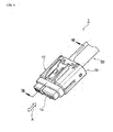
- Fig. 1 is a perspective view of a waterproof connector in this embodiment
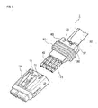
- Fig. 2 is an exploded perspective view of the waterproof connector in this embodiment
- Fig. 3 is an exploded perspective view of a connector body in this embodiment
- Fig. 4 is a perspective view of a first crimp terminal in this embodiment
- Fig. 5 is a perspective view of a first retainer in this embodiment
- Fig. 6 is a cross-sectional view along line VI-VI of Fig. 5
- Fig. 7 is a perspective view of a second retainer in this embodiment
- Fig. 8 is a cross-sectional perspective view along line VIII-VIII of Fig. 1
- Fig. 9 is a cross-sectional view along line IX-IX of Fig. 8
- Fig. 10 is a cross-sectional view illustrating a first seal member of the waterproof connector in this embodiment.
- a waterproof connector 1 in this embodiment is a connector that is attached to a wiring substrate 30 (wiring material) electrically connecting an electronic component (for example, a seat occupancy sensor, a capacitive sensor, or the like) with an electronic control unit (ECU) or the like in an automobile.
- the waterproof connector is attached to the other end of the wiring substrate of which one end is connected to an electronic component or the like, is assembled in a lower portion of a seat, and is connected to another connector.
- an arrow A illustrated in the drawings represents an inserting/separating direction in which the waterproof connector 1 is inserted into/separated from the another connector.
- the side (left side in the drawings) thereof which is to be connected to another connector is referred to as a front end side 1a and the side (right side in the drawings) thereof opposite to this is referred to as a rear end side 1b in the inserting/separating direction A.
- the waterproof connector 1 includes a housing 10, a connector body 20, and a second seal member 80.
- the housing 10 is a member that receives the connector body 20.
- Engaging holes 11, which are engaged with first and second claw portions 57 and 67 (to be described below) formed on first and second retainers 50 and 60 of the connector body 20, are formed at upper and lower portions of the housing 10. Note that, the engaging holes 11, which are positioned at the lower portion of the housing 10, are not illustrated.
- the connector body 20 includes the first retainer 50, the second retainer 60, and a first seal member 70.
- the first and second retainers 50 and 60 of this embodiment correspond to an example of a pair of retainers of the invention.
- the wiring substrate 30 is attached to the connector body 20.
- the wiring substrate 30 includes a first wiring substrate 31 and a second wiring substrate 32.
- the first and second wiring substrates 31 and 32 are disposed adjacent to each other so that a gap is formed between end portions of the first and second wiring substrates.
- the first wiring substrate 31 is a substrate where an electric circuit pattern (wiring) is formed on an insulating substrate.
- a flexible printed circuit (FPC) board, a rigid printed wiring board, a membrane that is made of polyethylene naphthalate (PEN), polyethylene terephthalate (PET), or the like, and the like may be mentioned as the first wiring substrate 31.
- the first wiring substrate 31 may comprise a substrate where wiring formed of rectangular conductors or round wires is laminated with an insulating substrate, or may comprise a flexible flat cable (FFC).
- first crimp terminals 41 are mounted on the end portion of the first wiring substrate 31.
- the first crimp terminals 41 are receptacle type terminals, and pin type terminals (not illustrated) provided on the ECU or the like are fitted to the first crimp terminals.
- the first crimp terminals 41 may be pin type terminals and may be fitted to receptacle type terminals.
- the first crimp terminal 41 includes a lower plate 41 a, an upper plate 41b, and barrels 41 c.
- the lower and upper plates 41a and 41b are members between which the first wiring substrate 31 is interposed.
- the barrels 41c are platelike members that stand on the side portions of the lower plate 41 a. In this embodiment, the barrels 41c are bent toward the upper plate 41b after being inserted into through holes (which are illustrated in Fig. 4 by a dotted line) formed in the first wiring substrate 31. Accordingly, the first wiring substrate 31 is fixed (crimped) between the lower and upper plates 41a and 41b.
- the second wiring substrate 32 is a substrate where an electric circuit pattern (wiring) is formed on an insulating substrate.
- an electric circuit pattern wiring
- a flexible printed circuit board, a rigid printed wiring board, a membrane, and the like may be mentioned as the second wiring substrate 32.
- the second wiring substrate 32 may comprise a substrate where wiring formed of rectangular conductors or round wires is laminated with an insulating substrate, or may comprise a flexible flat cable.
- two second crimp terminals 42 are mounted on the end portion of the second wiring substrate 32.
- the second crimp terminal 42 has the same structure as the structure of the first crimp terminal 41, and includes a lower plate, an upper plate, and barrels. The barrels are bent while the second wiring substrate 32 is interposed between the lower and upper plates. Accordingly, the second crimp terminal 42 is also crimped to the second wiring substrate 32.
- the wiring substrate 30 of this embodiment includes two wiring substrates 31 and 32.
- the wiring substrate 30 is not particularly limited, and may be comprise one wiring substrate.
- the wiring substrate 30 may comprise only the first wiring substrate 31 that includes five first crimp terminals 41 mounted on the end portion thereof.
- the number of the first crimp terminals 41 and the number of the second crimp terminals 42 are also not particularly limited, and may be appropriately set according to the number of terminals of another connector that is to be connected to the waterproof connector 1.
- the wiring substrate 30 is interposed between the first and second retainers 50 and 60 as illustrated in Fig. 3 , and the first retainer 50 receives a force, which is applied when the waterproof connector 1 is inserted or separated, together with the second retainer 60.
- first terminal receiving portions 52, a first inner groove 53, and first protrusions 54 are formed on a first opposite surface 51 of the first retainer 50 that faces the wiring substrate 30.
- first claw portions 57 are formed on a first outer surface 55 which is opposite to the first opposite surface 51 among the surfaces of the first retainer 50 that are along the inserting/separating direction A of the waterproof connector 1.
- a first outer groove 56 is continuously formed on the first outer surface 55 and first side surfaces 50d and 50e of the first retainer 50.
- the first side surfaces 50d and 50e are surfaces which cross the first opposite surface 51 and the first outer surface 55 among the surfaces of the first retainer 50 that are along the inserting/separating direction A of the waterproof connector 1.
- the first terminal receiving portions 52 are recesses that are formed along the inserting/separating direction A of the waterproof connector 1.
- the first terminal receiving portions 52 receive the upper plates 41 a, the lower plates 41b, and the barrels 41 of the respective first and second crimp terminals 41 and 42.
- three first terminal receiving portions 52 are disposed at the left side portion of the first retainer 50 in Fig. 5 and receive three first crimp terminals 41.
- two first terminal receiving portions 52 are disposed at the right side portion of the first retainer 50 in Fig. 5 and receive two second crimp terminals 42.
- the first inner groove 53 is formed on the first opposite surface 51 in a direction substantially orthogonal to the inserting/separating direction A.
- the first inner groove 53 is opened at the first side surfaces 50d and 50e so that the melted first seal member 70 flows into the first inner groove 53 through openings 53b of the first inner groove 53. Accordingly, the first inner groove 53 communicates with the first outer groove 56 through the openings 53b. Further, the first inner groove 53 forms an inner receiving portion 91, in which the melted first seal member 70 is to be filled, by being combined with a second inner groove 63 of the second retainer 60.
- the front end side 1a (see Fig. 1 ) with respect to the first inner groove 53 is referred to as a first front end portion 50a
- the rear end side 1b (see Fig. 1 ) with respect to the first inner groove 53 is referred to as a first rear end portion 50b.
- first front end portion 50a and the first rear end portion 50b of the first retainer 50 are partially connected to each other by first connecting portions 50c on which the first inner groove 53 (the inner receiving portion 91) is formed. That is, in this embodiment, a first defective portion 58 (to be described below) is formed between the first connecting portions 50c.
- a side seal portion 70c and a defective seal portion 70d reach the first outer surface 55 of the first connecting portions 50c and the first connecting portions 50c are surrounded by an inner seal portion 70a, an outer seal portion 70b, the side seal portion 70c, and the defective seal portion 70d.
- the inner seal portion 70a, the outer seal portion 70b, the side seal portion 70c, and the defective seal portion 70d will be described below.
- the first protrusions 54 protrude from a bottom 53a of the first inner groove 53 toward the inner receiving portion 91 and the upper ends of the first protrusions 54 come into contact with the wiring substrate 30.
- a plurality of first protrusions 54 are formed in the first inner groove 53 and ribs are formed between the first protrusions 54 except for a portion of the first inner groove 53 in which the first defective portion 58 is formed.
- the first outer groove 56 is formed on the first outer surface 55 and first side surfaces 50d and 50e of the first retainer 50 in a direction substantially orthogonal to the inserting/separating direction A. Further, the first outer groove 56 communicates with the first inner groove 53 through the openings 53b.
- the first outer groove 56 is combined with a second outer groove 66 of the second retainer 60, so that an outer receiving portion 92 receiving the first seal member 70 is formed on the outer surfaces 55 and 65 and the side surfaces 50d, 50e, 60d, and 60e of the first and second retainers 50 and 60.
- the first claw portions 57 are protruding portions that are formed on the first outer surface 55 of the first rear end portion 50b.
- the first claw portions 57 are fitted to the engaging holes 11 of the above-mentioned housing 10. Accordingly, the connector body 20 is fixed to the housing 10.
- the first seal member 70 is filled in the first defective portion 58.
- the first defective portion 58 will be described in detail.
- the first defective portion 58 passes between the bottom 53a of the first inner groove 53 and a bottom 56a of the first outer groove 56. Further, in plane view, the first defective portion 58 is formed over the entire overlap B between the outer receiving portion 92 and the inner receiving portion 91 in the inserting/separating direction A of the waterproof connector 1.
- the first defective portion 58 of this embodiment is an opening that is axisymmetric about a center line CL of the inner receiving portion 91 (the first inner groove 53) which is along the inserting/separating direction A of the waterproof connector 1.
- the first retainer 50 which has been described above, is made of a material that has thermal resistance higher than the melting temperature of the first seal member 70 to be described below and has a coefficient of linear expansion lower than that of the first seal member 70.
- the first seal member 70 is made of polyamide, for example, polybutylene terephtalate (PBT) may be mentioned as a material of the first retainer 50.
- the second retainer 60 is a member that makes the wiring substrate 30 be interposed between the first retainer 50 and itself. Note that, the second retainer 60 is separated from the first retainer 50 in this embodiment, but is not particularly limited. For example, the second retainer 60 may be connected to the first retainer 50 by a hinge or the like.
- second terminal receiving portions 62, a second inner groove 63, and second protrusions 64 are formed on a second opposite surface 61 of the second retainer 60 that faces the wiring substrate 30.
- second claw portions 67 are formed on a second outer surface 65, which is opposite to the second opposite surface 61, among the surfaces of the second retainer 60 that are along the inserting/separating direction A of the waterproof connector 1.
- the second outer groove 66 is continuously formed on the second outer surface 65 and second side surfaces 60d and 60e of the second retainer 60.
- the second side surfaces 60d and 60e are surfaces, which cross the second opposite surface 61 and the second outer surface 65, among the surfaces of the second retainer 60 that are along the inserting/separating direction A of the waterproof connector 1.
- the second terminal receiving portions 62 are recesses that are formed in the inserting/separating direction A so as to face the first terminal receiving portions 52 of the first retainer 50.
- the second terminal receiving portions 62 receive the first and second crimp terminals 41 and 42 together with the first terminal receiving portions 52.
- the second inner groove 63 is formed on the second opposite surface 61 along a direction substantially orthogonal to the inserting/separating direction A so as to face the first inner groove 53 of the first retainer 50.
- the second inner groove 63 forms the inner receiving portion 91, in which the melted first seal member 70 is to be filled, by being combined with the first inner groove 53 of the first retainer 50.
- the second inner groove 63 is also opened at the second side surfaces 60d and 60e so that the melted first seal member 70 flows into the second inner groove 63 through openings 63b of the second inner groove 63. Accordingly, the second inner groove 63 communicates with the second outer groove 66 through the openings 63b. For this reason, the inner receiving portion 91 of this embodiment communicates with the outer receiving portion 92 at the side surfaces 50d, 50e, 60d, and 60e of the first and second retainers 50 and 60.
- the front end side 1a (see Fig. 1 ) with respect to the second inner groove 63 is referred to as a second front end portion 60a
- the rear end side 1b (see Fig. 1 ) with respect to the second inner groove 63 (to be described below) is referred to as a second rear end portion 60b.
- second front end portion 60a and the second rear end portion 60b of the second retainer 60 are partially connected to each other by second connecting portions 60c on which the second inner groove 63 (the inner receiving portion 91) is formed. That is, in this embodiment, a second defective portion 68 (to be described below) is formed between the second connecting portions 60c.
- the side seal portion 70c and the defective seal portion 70d reach the second outer surface 65 of the second connecting portions 60c and the second connecting portions 60c are surrounded by the inner seal portion 70a, the outer seal portion 70b, the side seal portion 70c, and the defective seal portion 70d.
- the inner seal portion 70a, the outer seal portion 70b, the side seal portion 70c, and the defective seal portion 70d will be described below.
- the second protrusions 64 protrude from a bottom 63a of the second inner groove 63 toward the inner receiving portion 91 and the upper ends of the second protrusions 64 come into contact with the wiring substrate 30. Further, when the wiring substrate 30 is interposed between the first and second retainers 50 and 60, the second protrusions 64 are disposed so as to face the first protrusions 54, so that the wiring substrate 30 is interposed between the first and second protrusions 54 and 64.
- a plurality of second protrusions 64 are formed in the second inner groove 63 and ribs are formed between the second protrusions 64 except for a portion of the second inner groove 63 in which the second defective portion 68 (to be described below) is formed.
- the second outer groove 66 is formed on the second side surfaces 60d and 60e and the second outer surface 65 of the second retainer 60 in a direction substantially orthogonal to the inserting/separating direction A. Moreover, the second outer groove 66 communicates with the second inner groove 63 through the openings 63b.
- the second outer groove 66 is combined with the first outer groove 56 of the first retainer 50 so that the outer receiving portion 92 receiving the first seal member 70 is formed on the outer surfaces 55 and 65 and the side surfaces 50d, 50e, 60d, and 60e of the first and second retainers 50 and 60.
- the second claw portions 67 are protruding portions that are to be fitted to the engaging holes 11 of the above-mentioned housing 10.
- the second claw portions 67 are formed on the second outer surface 65 of the second rear end 60b (see Fig. 3 ).
- the second defective portion 68 which passes from the second outer surface 65 to the inner receiving portion 91, is formed in the second retainer 60 of this embodiment as illustrated in Fig. 7 , the melted first seal member 70 is also filled in the second defective portion 68.
- the second defective portion 68 will be described in detail.
- the second defective portion 68 passes between the bottom 63a of the second inner groove 63 and a bottom 66a of the second outer groove 66. Further, in plane view, the second defective portion 68 is formed over the entire overlap C between the inner receiving portion 91 and the outer receiving portion 92 in the inserting/separating direction A of the waterproof connector 1.
- the second defective portion 68 of this embodiment is an opening that is axisymmetric about a center line CL of the inner receiving portion 91 (the second inner groove 63) which is along the inserting/separating direction A of the waterproof connector 1. Furthermore, when the wiring substrate 30 is interposed between the first and second retainers 50 and 60, the second defective portion 68 is disposed so as to face the first defective portion 58.
- the size of the second defective portion 68 of this embodiment is substantially the same as that of the first defective portion 58, but is not particularly limited.
- the second defective portion 68 may be formed to be relatively smaller than the first defective portion 58.
- the second retainer 60 which has been described above, is made of a material that has thermal resistance higher than the melting temperature of the first seal member 70 and has a coefficient of linear expansion lower than that of the first seal member 70.
- the first seal member 70 is made of polyamide, for example, polybutylene terephtalate may be mentioned as a material of the second retainer 60.
- the first seal member 70 is filled in the inner receiving portion 91 and seals between the first retainer 50 and the wiring substrate 30 and between the second retainer 60 and the wiring substrate 30. Further, in this embodiment, the first seal member 70 is also received in the outer receiving portion 92.
- the first seal member 70 is made of a hot-melt seal material (hot-melt adhesive). Note that, for example, a thermoplastic resin material such as polyamide may be used as the material of the first seal member 70.
- the first seal member 70 includes the inner seal portion 70a, the outer seal portion 70b, the side seal portion 70c, and the defective seal portion 70d.
- the side seal portion 70c and the defective seal portion 70d of this embodiment correspond to an example of a connecting seal portion of the invention.
- the inner seal portion 70a is received in the inner receiving portion 91 and seals between the wiring substrate 30 and the first and second retainers 50 and 60.
- the outer seal portion 70b is received in the outer receiving portion 92 that is positioned on the outer surfaces 55 and 65 of the first and second retainers 50 and 60, and fixes the first and second retainers 50 and 60, which come into close contact with each other, through the side seal portion 70c.
- the side seal portion 70c is received in the outer receiving portion 92 that is positioned on the side surfaces 50d, 50e, 60d, and 60e of the first and second retainers 50 and 60; and is formed integrally with the inner seal portion 70a through the openings 53b and 63b of the inner grooves 53 and 63 of the first and second retainers 50 and 60.
- the side seal portion 70c reaches the outer surfaces 55 and 65 of the first and second retainers 50 and 60, and is connected to the outer seal portion 70b.
- the defective seal portion 70d is received in the first and second defective portions 58 and 68 of the first and second retainers 50 and 60 and is formed integrally with the inner seal portion 70a. Further, the defective seal portion 70d reaches the outer surfaces 55 and 65 of the first and second retainers 50 and 60 and is connected to the outer seal portion 70b.
- the second seal member 80 surrounds the connector body 20 (the first and second retainers 50 and 60) and seals between the housing 10 and the connector body 20.
- the second seal member 80 may be mentioned as the second seal member 80.
- grooves 81 are formed on the outer peripheral surface of the second seal member 80 coming into contact with the housing 10 so that the adhesion between the housing 10 and the second seal member 80 is improved.
- convex portions 82 which string in a ring shape, are formed on the inner peripheral surface of the second seal member 80 coming into contact with the connector body 20 (the first seal member 70). Accordingly, the positional deviation between the connector body 20 and the second seal member 80 is suppressed and the adhesion between the connector body 20 and the second seal member 80 is improved.
- the wiring substrate 30 is interposed between the first and second retainers 50 and 60 for the mechanical reinforcement.
- the first and second retainers 50 and 60 are combined with each other and function as a single reinforcing member.
- first seal member 70 made of a hot-melt seal material seals between the wiring substrate 30 and the first and second retainers 50 and 60, and waterproofs the waterproof connector 1 (particularly, the crimp terminals 41 and 42).
- the first and second retainers 50 and 60, between which the wiring substrate 30 has been interposed, are set in a die (not illustrated) and the first seal member 70 (hot-melt seal material), which is melted by heating, is filled in at least the inner receiving portion 91 and is solidified by cooling.
- the first seal member 70 hot-melt seal material
- the first seal member 70 is made of polyamide, about 185°C may be mentioned as heating temperature for the melting of the first seal member 70.
- the adhesion between the first seal member and the retainers may deteriorate due to thermal stress that is generated between the first seal member and the retainers (particularly, the opposite surfaces) in connection with the solidification of the first seal member 70 filled between the wiring substrate 30 and the first and second retainers 50 and 60 or fatigue that occurs due to the change of thermal stress caused by temperature change during the use of the waterproof connector. For this reason, there is a case that the waterproof performance of the waterproof connector may not be sufficiently improved.
- the side seal portion 70c received in the outer receiving portion 92 reaches the outer surfaces 55 and 65 of the first and second retainers 50 and 60 as illustrated in Fig. 9 .
- the first and second defective portions 58 and 68 are formed in the first and second retainers 50 and 60 and the defective seal portion 70d received in the first and second defective portions 58 and 68 also reaches the outer surfaces 55 and 65.
- the side seal portion 70c and the inner seal portion 70a are formed integrally, and the defective seal portion 70d and the inner seal portion 70a are formed integrally.
- the rigidity of the first and second retainers 50 and 60 is low. Accordingly, the first and second retainers 50 and 60 are easily deformed following the shrinkage of the inner seal portion 70a or the side seal portion 70c and the defective seal portion 70d.
- thermal stress (which is illustrated by arrows of Fig. 9 ) generated between the first seal member 70 and the first and second retainers 50 and 60 is reduced, so that the strong adhesion between the first seal member 70 (the inner seal portion 70a) and the first and second retainers 50 and 60 (the bottoms 53a and 63a of the first and second inner grooves 53 and 63) is maintained. Accordingly, it is possible to improve waterproof performance. Further, when the retainers are increased in size due to the increase of the number of the terminals of the waterproof connector, the above-mentioned effects are particularly significant.
- the waterproof performance of the waterproof connector 1 in this embodiment is to be improved, and particularly, the durability of the waterproof connector 1 is improved under thermal cycle (which repeats to apply temperature of -40°C to 85°C). Accordingly, the life of the waterproof connector 1 itself is lengthened.
- the first seal member 70 includes the inner seal portion 70a, the side seal portion 70c, and defective seal portion 70d as illustrated in Fig. 10 as described above, the above-mentioned effects are obtained. Accordingly, the first seal member 70 does not need to include the outer seal portion 70b. However, if the first seal member 70 includes the outer seal portion 70b, the following effects are further obtained.
- the outer seal portion 70b since the outer seal portion 70b is connected to the inner seal portion 70a through the side seal portion 70c and the defective seal portion 70d, the outer seal portion 70b presses the outer surfaces 55 and 65 of the first and second retainers 50 and 60 in addition to the side seal portion 70c and the defective seal portion 70d when the first seal member 70 shrinks.
- first and second retainers 50 and 60 are more easily deformed so as to follow the shrinkage of the inner seal portion 70a, so that the thermal stress generated between the first seal member 70 and the first and second retainers 50 and 60 is further reduced. Accordingly, the strong adhesion between the first seal member 70 and the first and second retainers 50 and 60 is maintained in the waterproof connector 1 of this embodiment, so that it is possible to effectively improve waterproof performance.
- the first defective portion 58 passes through the overlap B of the first retainer 50 between the inner and outer receiving portions 91 and 92 in plane view. Furthermore, the first defective portion 58 is formed over the entire overlap B in the inserting/separating direction A of the waterproof connector 1.
- the second defective portion 68 also passes through the overlap C of the second retainer 60 between the inner and outer receiving portions 91 and 92 in plane view. Moreover, the second defective portion 68 is formed over the entire overlap C in the inserting/separating direction A of the waterproof connector 1.
- first and second defective portions 58 and 68 By forming the first and second defective portions 58 and 68 over a wide range along the inserting/separating direction A of the waterproof connector 1, it is possible to ensure the strong adhesion between the first seal member 70 and the first and second retainers 50 and 60 over a wide range.
- the first and second defective portions 58 and 68 face each other as illustrated in Fig. 9 .
- the wiring substrate 30 is interposed between the first and second retainers 50 and 60 together with the first seal member 70 even in the inner receiving portion 91. Accordingly, since the thermal stress generated between the first retainer 50 and the first seal member 70 and the thermal stress generated between the second retainer 60 and the first seal member 70 are generated so as to be axisymmetric about the wiring substrate 30, it is possible to suppress the distortion or bending of the wiring substrate 30.
- the thermal stress generated between the first retainer 50 and the first seal member 70 is substantially the same as the thermal stress generated between the second retainer 60 and the first seal member 70. Accordingly, it is possible to further suppress the distortion or bending of the wiring substrate 30.
- the wiring substrate 30 is interposed between the first and second protrusions 54 and 64 in the inner receiving portion 91. Accordingly, when the inner receiving portion 91 is filled with the melted first seal member 70, the attitude of the wiring substrate 30 is stable.
- the first and second defective portions 58 and 68 are axisymmetric about the center line CL of the inner receiving portion 91 in the inserting/separating direction A of the waterproof connector 1. For this reason, the waterproof connector 1 in this embodiment can receive a force, which is applied when the waterproof connector is inserted or separated, with a good balance and can suppress the deformation of the first and second retainers 50 and 60 when the waterproof connector 1 is inserted or separated.
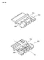
- Figs. 11 to 16 are perspective views illustrating modifications of first and second retainers in this embodiment
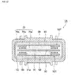
- Fig. 17 is a cross-sectional view illustrating a modification of the waterproof connector in this embodiment
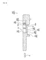
- Fig. 18 is a cross-sectional view of a retainer of the waterproof connector illustrated in Fig. 17
- Fig. 19 is a cross-sectional view illustrating a first seal member of the modification of the waterproof connector in this embodiment.
- the first defective portion 58 has been formed in the first retainer 50 and the second defective portion 68 has been formed in the second retainer 60.
- the first and second defective portions 58 and 68 are not particularly limited, and a defective portion may be formed in at least one of the retainers.
- a first defective portion 58 may be formed only in a first retainer 501 and a defective portion may not be formed in a second retainer 601. Since the adhesion between the first retainer 501 and a wiring substrate is maintained even in this case, the waterproof performance of the waterproof connector 1 is improved.
- first and second defective portions 58 and 68 are "openings" in this embodiment, but are not particularly limited.
- first and second defective portions 581 and 681 of first and second retainers 502 and 602 may be "cutouts" as illustrated in Fig. 12 .
- the first defective portion 581 in this case includes first and second cutouts 581a and 581b that are formed on both ends of the first inner groove 53 so as to have substantially the same size.
- the second defective portion 681 also includes third and fourth cutouts 681a and 681b that are formed on both ends of the second inner groove 63 so as to have substantially the same size.
- the first cutout 581a and the third cutout 681 a have substantially the same size and face each other.
- the second cutout 581b and the fourth cutout 681b have substantially the same size and face each other.
- the term of "both ends” mentioned here means ends in the direction substantially orthogonal to the inserting/separating direction A of the waterproof connector 1.
- a side seal portion and a defective seal portion which is received in the cutouts 581a, 581b, 681 a, and 681b, are formed integrally.
- the side seal portion and the defective seal portion which are formed integrally, reach the outer surface and pull the first and second retainers 502 and 602 toward the inner seal portion.
- the cutouts 581a, 581b, 681a, and 681b are formed in the first and second retainers 502 and 602, the rigidity of the first and second retainers 502 and 602 is low. Accordingly, the first and second retainers 502 and 602 are easily deformed following the shrinkage of the inner seal portion or the defective seal portion.
- thermal stress generated between the first seal member and the first and second retainers 502 and 602 is reduced, so that the strong sealing between the first seal member and the first and second retainers 502 and 602 is maintained.
- the outer seal portion presses the outer surfaces of the first and second retainers 502 and 602 in addition to the defective seal portion, the thermal stress generated between the first seal member and the first and second retainers 502 and 602 is further reduced.
- first and second defective portions 581 and 681 face each other in the first and second retainers 502 and 602. For this reason, since a wiring substrate is interposed between the first and second retainers 502 and 602 together with the first seal member even in the inner receiving portion 91, it is possible to suppress the occurrence of the distortion or bending of the wiring substrate.
- the first and second defective portions 581 and 681 of the first and second retainers 502 and 602 are axisymmetric about the center line CL of the inner receiving portion 91 in the inserting/separating direction A of the waterproof connector 1. For this reason, the waterproof connector 1 in this embodiment can receive a force, which is applied when the waterproof connector is inserted or separated, with a good balance and can suppress the deformation of the first and second retainers 502 and 602 when the waterproof connector 1 is inserted or separated.
- a first defective portion 582 of a first retainer 503 may include first and second cutouts 582a and 682b having different sizes.
- the first cutout 582a positioned on the left side in the figure may be formed so as to be relatively large
- the second cutout 582b positioned on the right side in the figure may be formed so as to be relatively smaller than the first cutout 582a.
- a second defective portion 682 of a second retainer 603 may also include third and fourth cutouts 682a and 682b having different sizes.
- the third cutout 682a positioned on the left side in the figure may be formed so as to be relatively large and face the first cutout 582a
- the fourth cutout 682b positioned on the right side in the figure may be formed so as to be relatively small and face the second cutout 582b.
- the first and second defective portions 582 and 682 of the first and second retainers 503 and 603 face each other. For this reason, since a wiring substrate is interposed between the first and second retainers 503 and 603 together with the first seal member even in the inner receiving portion 91, it is possible to suppress the occurrence of the distortion or bending of the wiring substrate.
- first and second defective portions 583 and 683 may be formed of cutouts and may be disposed so as to be axisymmetric about the center line CL of the inner receiving portion 91 in the inserting/separating direction A of the waterproof connector 1 when first and second retainers 504 and 604 are combined with each other. Even the first and second retainers 504 and 604 are assembled in the waterproof connector 1, it is possible to improve waterproof performance while suppressing the deformation of the first and second retainers 504 and 604 when the waterproof connector 1 is inserted or separated.
- the first defective portion 583 includes two cutouts and the second defective portion 683 also includes two cutouts in the figure, but the first and second defective portions 583 and 683 are not particularly limited.
- the first defective portion 583 may include one cutout and the second cutout 683 may also include one cutout.
- a first defective portion 584 may nclude a first opening 584a and first and second cutouts 584b and 584c.
- a second defective portion 684 may include a second opening 684a and third and fourth cutouts 684b and 684c.
- the first opening 584a is disposed in the middle portion of the first inner groove 53 and the first and second cutouts 584b and 584c are disposed on both ends of the first inner groove 53.
- the second opening 684a is disposed in the middle portion of the second inner groove 63 and the third and fourth cutouts 684b and 684c are disposed on both ends of the second inner groove 63.
- the "both ends” mentioned here mean ends in the direction substantially orthogonal to the inserting/separating direction A of the waterproof connector 1.
- the first and second defective portions 584 and 684 of the first and second retainers 505 and 605 face each other. For this reason, since a wiring substrate is interposed between the first and second retainers 505 and 605 together with the first seal member even in the inner receiving portion, it is possible to suppress the occurrence of the distortion or bending of the wiring substrate.
- first and second defective portions 584 and 684 are axisymmetric about the center line CL of the inner receiving portion 91 in the inserting/separating direction A of the waterproof connector 1. For this reason, even the first and second retainers 505 and 605 are assembled in the waterproof connector 1, it is possible to effectively improve waterproof performance while suppressing the deformation of the first and second retainers 505 and 605 when the waterproof connector 1 is inserted or separated.
- first and second defective portions 585 and 685 may include a plurality of circular openings.
- the plurality of (five in this example) openings that form the first defective portion 585 and the plurality of (five in this example) openings that form the second defective portion 685 are formed so as to be axisymmetric about the center line CL of the inner receiving portion 91 in the inserting/separating direction A of the waterproof connector 1.
- the plurality of openings that form the first defective portion 584 and the plurality of openings that form the second defective portion 684 are disposed so as to face each other.
- first and second retainers 506 and 606 in which the first and second defective portions 585 and 685 are formed are assembled in the waterproof connector 1, it is possible to effectively improve waterproof performance while suppressing the deformation of the first and second retainers 506 and 606 when the waterproof connector 1 is inserted or separated.
- the first and second defective portions 585 and 685 include relatively large openings and relatively small openings in the example illustrated in the figure, but are not particularly limited.
- the plurality of openings may have the same size.
- the shapes of the openings are also not particularly limited.
- the first and second defective portions 58 and 68 have been formed in the first and second retainers 50 and 60, respectively, for the improvement of the waterproof performance of the waterproof connector 1.
- the invention is not limited thereto.
- a first thin portion 59 which is formed by partially thinning the thickness between a first outer surface 55 and a bottom 91a of an inner receiving portion 91, may be formed at a first retainer 507 and a second thin portion 69, which is formed by partially thinning the thickness between a second outer surface 65 and a bottom 91 a of an inner receiving portion 91, may also be formed at a second retainer 607.
- the bottoms 91a of the inner receiving portions 91 which are mentioned here, are the bottoms 53a and 63a of the first and second inner grooves 53 and 63 except for the first and second protrusions or the ribs.
- a first seal member 70 of this waterproof connector 1A includes an inner seal portion 70a, an outer seal portion 70b, and a side seal portion 70c.
- the side seal portion 70c pulls the first and second retainers 507 and 607 toward the inner seal portion 70a.
- the side seal portion 70c corresponds to an example of a connecting seal portion of the invention.
- first and second thin portions 59 and 69 of the first and second retainers 507 and 607 have relatively low rigidity, the first and second thin portions 59 and 69 are easily deformed following the shrinkage of the first seal member 70. Accordingly, it is possible to maintain the adhesion between the first seal member 70 and the first and second retainers 507 and 607, so that it is possible to improve waterproof performance.
- the first seal member 70 of the waterproof connector 1A of this example includes the inner seal portion 70a and the outer seal portion 70c as illustrated in Fig. 19 , the above-mentioned effects are obtained. Accordingly, the first seal member 70 does not need to include the outer seal portion 70b. However, if the first seal member 70 includes the outer seal portion 70b, the following effects are obtained.
- the outer seal portion 70b presses the outer surfaces 55 and 65 of the first and second retainers 507 and 607 in addition to the side seal portion 70c, the first and second retainers 507 and 607 are more easily deformed following the shrinkage of the first seal member 70. For this reason, it is possible to maintain the strong adhesion between the first seal member 70 and the first and second retainers 507 and 607, so that it is possible to effectively improve waterproof performance.
- first and second thin portions 59 and 69 have been formed at the first and second retainers 507 and 607 in the example illustrated in the figure, but a thin portion may be formed only on one retainer.
- first thin portion 59 is formed only at the first retainer 507, and a thin portion may not be formed at the second retainer 607.
Landscapes
- Connector Housings Or Holding Contact Members (AREA)
Abstract
Description
- The present invention relates to a waterproof connector that is used for the electrical connection of a wiring substrate.
- As for a designated State where incorporation of a document by reference is allowed, the contents of Japanese Patent Application No.
2010-083185 - A waterproof connector for a flexible substrate, where a flexible substrate on which terminals are mounted is held by a pair of retainers and a hot melt is filled between the flexible substrate and the retainer, is known (for example, see Patent Document 1).
- Patent Document 1:
WO 2009/090998 A - In the above-mentioned waterproof connector for a flexible substrate, there is a case that it is not possible to sufficiently improve the waterproof performance since the adhesion between the hot melt and the retainers deteriorates due to the shrinkage of the hot melt that is caused by the solidification of the hot melt filled between the flexible substrate and the retainers or fatigue that is caused by the change of the amount of the shrinkage of the hot melt during the use of the waterproof connector.
- An object to be achieved by the invention is to provide a waterproof connector having excellent waterproof performance.
- A waterproof connector according to the invention is a waterproof connector which is attached to a wiring substrate is characterized by comprising: a pair of retainers between which the wiring substrate is interposed and which include an inner receiving portion formed on opposite surfaces which face the wiring substrate; and a first seal member which is made of a hot-melt seal material and is filled in at least the inner receiving portion, wherein an outer receiving portion in which the first seal member is received is formed on outer surfaces and side surfaces among surfaces of the pair of retainers which are along an inserting/separating direction of the waterproof connector, the outer surfaces which are opposite to the opposite surfaces, the side surfaces which cross the opposite surfaces and the outer surfaces, a defective portion, which passes from the outer surface to the inner receiving portion and in which the first seal member is to be filled, is formed in at least one of the retainers, the inner receiving portion communicates with the outer receiving portion at the side surfaces, the defective portion includes at least one of an opening or a cutout, the first seal member includes: an inner seal portion which is received in the inner receiving portion; and a connecting seal portion which is received in the defective portion and the outer receiving portion positioned on the side surfaces of the retainers and is formed integrally with the inner seal portion, and the connecting seal portion reaches the outer surfaces of the retainers.
- In the invention, the defective portion may be formed over the entire overlap between the outer receiving portion and the inner receiving portion in an inserting/separating direction of the waterproof connector.
- In the invention, the defective portion may be disposed so as to be axisymmetric about a center line of the inner receiving portion in the inserting/separating direction of the waterproof connector.
- In the invention, the retainers may include a first retainer and a second retainer, the defective portion may include: a first defective portion which is formed in the first retainer; and a second defective portion which is formed in the second retainer, and the first and second defective portions may be disposed so as to face each other.
- In the invention, a first protrusion, which protrudes toward the inside of the inner receiving portion, may be formed on the first retainer, a second protrusion, which protrudes toward the inside of the inner receiving portion, may be formed on the second retainer, and the first and second protrusions may be disposed so as to face each other.
- A waterproof connector according to the invention is a waterproof connector which is attached to a wiring substrate is characterized by comprising: a pair of retainers between which the wiring substrate is interposed and which include an inner receiving portion formed on opposite surfaces which face the wiring substrate; and a first seal member which is made of a hot-melt seal material and is filled in at least the inner receiving portion, wherein an outer receiving portion in which the first seal member is received is formed on outer surfaces and side surfaces among surfaces of the pair of retainers which are along an inserting/separating direction of the waterproof connector, the outer surfaces which are opposite to the opposite surfaces, the side surfaces which cross the opposite surfaces and the outer surfaces, a thin portion, which is formed by partially thinning the thickness between the outer surface and a bottom of the inner receiving portion, is formed in at least one of the retainers, the inner receiving portion communicates with the outer receiving portion at the side surfaces, the first seal member includes: an inner seal portion which is received in the inner receiving portion, and a connecting seal portion which is received in the outer receiving portion positioned on the side surfaces of the retainers and is formed integrally with the inner seal portion, the connecting seal portion reaches the outer surfaces of the retainers.
- A waterproof connector according to the invention is a waterproof connector which is attached to a wiring substrateis characterized by comprising: a pair of retainers between which the wiring substrate is interposed and which include an inner receiving portion formed on opposite surfaces which face the wiring substrate, and a first seal member which is made of a hot-melt seal material and is filled in at least the inner receiving portion, wherein the retainers include: front end portions which are positioned on front end side of the retainers from the inner receiving portion in an inserting/separating direction of the waterproof connector; rear end portions which are positioned on rear end side of the retainers from the inner receiving portion in an inserting/separating direction of the waterproof connector; and connecting portions which partially connect the front end portions with the rear end portions and include the inner receiving portion, and the first seal member is received in the inner receiving portion and reaches outer surfaces of the connecting portions which are opposite to the opposite surfaces.
- In the invention, the waterproof connector may further comprises: a connector body which includes the first seal member and the pair of retainers; a housing which receives the connector body; and a second seal member which is interposed between the connector body and the housing and seals between the connector body and the housing.
- According to the invention, a defective portion, which passes to an inner receiving portion from an outer surface, is formed in at least one of retainers, a first seal member includes: an inner seal portion that is received in the inner receiving portion; and a connecting seal portion that is received in the defective portion and an outer receiving portion positioned on the side surfaces of the retainers and is formed integrally with the inner seal portion, and the connecting seal portion reaches the outer surfaces of the retainers. Accordingly, it is possible to improve waterproof performance.
- Further, according to the invention, a thin portion, which is formed by partially thinning the thickness between an outer surface and a bottom of an inner receiving portion, is formed in at least one of retainers, a first seal member includes: an inner seal portion that is received in the inner receiving portion; and a connecting seal portion that is received in an outer receiving portion positioned on side surfaces of the retainers and is formed integrally with the inner seal portion, and the connecting seal portion reaches the outer surfaces of the retainers. Accordingly, it is possible to improve waterproof performance.
- Furthermore, according to the invention, retainers include connecting portions that partially connect front end portions with rear end portions, and a first seal member is received in an inner receiving portion and reaches outer surfaces of the connecting portions. Accordingly, it is possible to improve waterproof performance.
-
-
Fig. 1 is a perspective view of a waterproof connector in an embodiment of the invention. -
Fig. 2 is an exploded perspective view of the waterproof connector in the embodiment of the invention. -
Fig. 3 is an exploded perspective view of a connector body in the embodiment of the invention. -
Fig. 4 is a perspective view of a first crimp terminal in the embodiment of the invention. -
Fig. 5 is a perspective view of a first retainer in the embodiment of the invention. -
Fig. 6 is a cross-sectional view along line VI-VI ofFig. 5 . -
Fig. 7 is a perspective view of a second retainer of the embodiment of the invention. -
Fig. 8 is a cross-sectional perspective view along line VIII-VIII ofFig. 1 . -
Fig. 9 is a cross-sectional view along line IX-IX ofFig. 8 . -
Fig. 10 is a cross-sectional view illustrating a first seal member of the waterproof connector in the embodiment of the invention. -
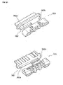
Fig. 11 is a perspective view illustrating a first modification of first and second retainers in the embodiment of the invention. -
Fig. 12 is a perspective view illustrating a second modification of the first and second retainers in the embodiment of the invention. -
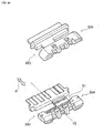
Fig. 13 is a perspective view illustrating a third modification of the first and second retainers in the embodiment of the invention. -
Fig. 14 is a perspective view illustrating a fourth modification of the first and second retainers in the embodiment of the invention. -
Fig. 15 is a perspective view illustrating a fifth modification of the first and second retainers in the embodiment of the invention. -
Fig. 16 is a perspective view illustrating a sixth modification of the first and second retainers in the embodiment of the invention. -
Fig. 17 is a cross-sectional view illustrating a modification of the waterproof connector in the embodiment of the invention. -
Fig. 18 is a cross-sectional view of a retainer of the waterproof connector illustrated inFig. 17 . -
Fig. 19 is a cross-sectional view illustrating a first seal member of the modification of the waterproof connector in the embodiment of the invention. - An embodiment of the invention will be described below with reference to the drawings.
-
Fig. 1 is a perspective view of a waterproof connector in this embodiment,Fig. 2 is an exploded perspective view of the waterproof connector in this embodiment,Fig. 3 is an exploded perspective view of a connector body in this embodiment,Fig. 4 is a perspective view of a first crimp terminal in this embodiment,Fig. 5 is a perspective view of a first retainer in this embodiment,Fig. 6 is a cross-sectional view along line VI-VI ofFig. 5 ,Fig. 7 is a perspective view of a second retainer in this embodiment,Fig. 8 is a cross-sectional perspective view along line VIII-VIII ofFig. 1 ,Fig. 9 is a cross-sectional view along line IX-IX ofFig. 8 , andFig. 10 is a cross-sectional view illustrating a first seal member of the waterproof connector in this embodiment. - A waterproof connector 1 (see
Fig. 1 ) in this embodiment is a connector that is attached to a wiring substrate 30 (wiring material) electrically connecting an electronic component (for example, a seat occupancy sensor, a capacitive sensor, or the like) with an electronic control unit (ECU) or the like in an automobile. For example, the waterproof connector is attached to the other end of the wiring substrate of which one end is connected to an electronic component or the like, is assembled in a lower portion of a seat, and is connected to another connector. Note that, an arrow A illustrated in the drawings represents an inserting/separating direction in which the waterproof connector 1 is inserted into/separated from the another connector. Further, concerning the waterproof connector 1 in this embodiment, the side (left side in the drawings) thereof which is to be connected to another connector is referred to as afront end side 1a and the side (right side in the drawings) thereof opposite to this is referred to as arear end side 1b in the inserting/separating direction A. - As illustrated in
Fig. 2 , the waterproof connector 1 includes ahousing 10, aconnector body 20, and asecond seal member 80. - As illustrated in
Fig. 2 , thehousing 10 is a member that receives theconnector body 20. Engagingholes 11, which are engaged with first andsecond claw portions 57 and 67 (to be described below) formed on first andsecond retainers connector body 20, are formed at upper and lower portions of thehousing 10. Note that, theengaging holes 11, which are positioned at the lower portion of thehousing 10, are not illustrated. - As illustrated in
Fig. 3 , theconnector body 20 includes thefirst retainer 50, thesecond retainer 60, and afirst seal member 70. Note that, the first andsecond retainers wiring substrate 30 is attached to theconnector body 20. - As illustrated in
Fig. 3 , thewiring substrate 30 includes afirst wiring substrate 31 and asecond wiring substrate 32. The first andsecond wiring substrates - The
first wiring substrate 31 is a substrate where an electric circuit pattern (wiring) is formed on an insulating substrate. For example, a flexible printed circuit (FPC) board, a rigid printed wiring board, a membrane that is made of polyethylene naphthalate (PEN), polyethylene terephthalate (PET), or the like, and the like may be mentioned as thefirst wiring substrate 31. Further, thefirst wiring substrate 31 may comprise a substrate where wiring formed of rectangular conductors or round wires is laminated with an insulating substrate, or may comprise a flexible flat cable (FFC). - As illustrated in
Fig. 3 , threefirst crimp terminals 41 are mounted on the end portion of thefirst wiring substrate 31. Thefirst crimp terminals 41 are receptacle type terminals, and pin type terminals (not illustrated) provided on the ECU or the like are fitted to the first crimp terminals. Note that, thefirst crimp terminals 41 may be pin type terminals and may be fitted to receptacle type terminals. - As illustrated in
Fig. 4 , thefirst crimp terminal 41 includes alower plate 41 a, anupper plate 41b, and barrels 41 c. - The lower and
upper plates first wiring substrate 31 is interposed. Thebarrels 41c are platelike members that stand on the side portions of thelower plate 41 a. In this embodiment, thebarrels 41c are bent toward theupper plate 41b after being inserted into through holes (which are illustrated inFig. 4 by a dotted line) formed in thefirst wiring substrate 31. Accordingly, thefirst wiring substrate 31 is fixed (crimped) between the lower andupper plates - Like the
first wiring substrate 31, thesecond wiring substrate 32 is a substrate where an electric circuit pattern (wiring) is formed on an insulating substrate. For example, a flexible printed circuit board, a rigid printed wiring board, a membrane, and the like may be mentioned as thesecond wiring substrate 32. Further, thesecond wiring substrate 32 may comprise a substrate where wiring formed of rectangular conductors or round wires is laminated with an insulating substrate, or may comprise a flexible flat cable. - As illustrated in
Fig. 3 , twosecond crimp terminals 42 are mounted on the end portion of thesecond wiring substrate 32. Note that, thesecond crimp terminal 42 has the same structure as the structure of thefirst crimp terminal 41, and includes a lower plate, an upper plate, and barrels. The barrels are bent while thesecond wiring substrate 32 is interposed between the lower and upper plates. Accordingly, thesecond crimp terminal 42 is also crimped to thesecond wiring substrate 32. - The
wiring substrate 30 of this embodiment includes twowiring substrates wiring substrate 30 is not particularly limited, and may be comprise one wiring substrate. For example, thewiring substrate 30 may comprise only thefirst wiring substrate 31 that includes fivefirst crimp terminals 41 mounted on the end portion thereof. Moreover, the number of thefirst crimp terminals 41 and the number of thesecond crimp terminals 42 are also not particularly limited, and may be appropriately set according to the number of terminals of another connector that is to be connected to the waterproof connector 1. - The
wiring substrate 30 is interposed between the first andsecond retainers Fig. 3 , and thefirst retainer 50 receives a force, which is applied when the waterproof connector 1 is inserted or separated, together with thesecond retainer 60. - As illustrated in
Figs. 5 and6 , firstterminal receiving portions 52, a firstinner groove 53, andfirst protrusions 54 are formed on a firstopposite surface 51 of thefirst retainer 50 that faces thewiring substrate 30. Meanwhile,first claw portions 57 are formed on a firstouter surface 55 which is opposite to the firstopposite surface 51 among the surfaces of thefirst retainer 50 that are along the inserting/separating direction A of the waterproof connector 1. Further, a firstouter groove 56 is continuously formed on the firstouter surface 55 and first side surfaces 50d and 50e of thefirst retainer 50. Note that, as illustrated inFig. 5 , the first side surfaces 50d and 50e are surfaces which cross the firstopposite surface 51 and the firstouter surface 55 among the surfaces of thefirst retainer 50 that are along the inserting/separating direction A of the waterproof connector 1. - As illustrated in
Fig. 5 , the firstterminal receiving portions 52 are recesses that are formed along the inserting/separating direction A of the waterproof connector 1. The firstterminal receiving portions 52 receive theupper plates 41 a, thelower plates 41b, and thebarrels 41 of the respective first andsecond crimp terminals terminal receiving portions 52 are disposed at the left side portion of thefirst retainer 50 inFig. 5 and receive threefirst crimp terminals 41. Meanwhile, two firstterminal receiving portions 52 are disposed at the right side portion of thefirst retainer 50 inFig. 5 and receive twosecond crimp terminals 42. - As illustrated in
Fig. 5 , the firstinner groove 53 is formed on the firstopposite surface 51 in a direction substantially orthogonal to the inserting/separating direction A. The firstinner groove 53 is opened at the first side surfaces 50d and 50e so that the meltedfirst seal member 70 flows into the firstinner groove 53 throughopenings 53b of the firstinner groove 53. Accordingly, the firstinner groove 53 communicates with the firstouter groove 56 through theopenings 53b. Further, the firstinner groove 53 forms aninner receiving portion 91, in which the meltedfirst seal member 70 is to be filled, by being combined with a secondinner groove 63 of thesecond retainer 60. - Here, as illustrated in
Fig. 6 , in thefirst retainer 50 of this embodiment, thefront end side 1a (seeFig. 1 ) with respect to the firstinner groove 53 is referred to as a firstfront end portion 50a, and therear end side 1b (seeFig. 1 ) with respect to the firstinner groove 53 is referred to as a firstrear end portion 50b. - Further, the first
front end portion 50a and the firstrear end portion 50b of thefirst retainer 50 are partially connected to each other by first connectingportions 50c on which the first inner groove 53 (the inner receiving portion 91) is formed. That is, in this embodiment, a first defective portion 58 (to be described below) is formed between the first connectingportions 50c. - Here, when the waterproof connector 1 has been assembled, as illustrated in
Figs. 9 and10 , aside seal portion 70c and adefective seal portion 70d reach the firstouter surface 55 of the first connectingportions 50c and the first connectingportions 50c are surrounded by aninner seal portion 70a, anouter seal portion 70b, theside seal portion 70c, and thedefective seal portion 70d. Note that, theinner seal portion 70a, theouter seal portion 70b, theside seal portion 70c, and thedefective seal portion 70d will be described below. - As illustrated in
Figs. 5 and6 , thefirst protrusions 54 protrude from a bottom 53a of the firstinner groove 53 toward the inner receivingportion 91 and the upper ends of thefirst protrusions 54 come into contact with thewiring substrate 30. In this embodiment, a plurality offirst protrusions 54 are formed in the firstinner groove 53 and ribs are formed between thefirst protrusions 54 except for a portion of the firstinner groove 53 in which the firstdefective portion 58 is formed. - As illustrated in
Figs. 5 and6 , the firstouter groove 56 is formed on the firstouter surface 55 and first side surfaces 50d and 50e of thefirst retainer 50 in a direction substantially orthogonal to the inserting/separating direction A. Further, the firstouter groove 56 communicates with the firstinner groove 53 through theopenings 53b. - The first
outer groove 56 is combined with a secondouter groove 66 of thesecond retainer 60, so that an outer receivingportion 92 receiving thefirst seal member 70 is formed on theouter surfaces second retainers - As illustrated in
Fig. 6 , thefirst claw portions 57 are protruding portions that are formed on the firstouter surface 55 of the firstrear end portion 50b. Thefirst claw portions 57 are fitted to the engagingholes 11 of the above-mentionedhousing 10. Accordingly, theconnector body 20 is fixed to thehousing 10. - Moreover, since the first
defective portion 58, which passes to the inner receivingportion 91 from the firstouter surface 55, is formed in thefirst retainer 50 of this embodiment as illustrated inFigs. 5 and6 , thefirst seal member 70 is filled in the firstdefective portion 58. - The first
defective portion 58 will be described in detail. The firstdefective portion 58 passes between the bottom 53a of the firstinner groove 53 and a bottom 56a of the firstouter groove 56. Further, in plane view, the firstdefective portion 58 is formed over the entire overlap B between the outer receivingportion 92 and the inner receivingportion 91 in the inserting/separating direction A of the waterproof connector 1. As illustrated inFig. 5 , the firstdefective portion 58 of this embodiment is an opening that is axisymmetric about a center line CL of the inner receiving portion 91 (the first inner groove 53) which is along the inserting/separating direction A of the waterproof connector 1. - The
first retainer 50, which has been described above, is made of a material that has thermal resistance higher than the melting temperature of thefirst seal member 70 to be described below and has a coefficient of linear expansion lower than that of thefirst seal member 70. For example, if thefirst seal member 70 is made of polyamide, for example, polybutylene terephtalate (PBT) may be mentioned as a material of thefirst retainer 50. - As illustrated in
Fig. 3 , thesecond retainer 60 is a member that makes thewiring substrate 30 be interposed between thefirst retainer 50 and itself. Note that, thesecond retainer 60 is separated from thefirst retainer 50 in this embodiment, but is not particularly limited. For example, thesecond retainer 60 may be connected to thefirst retainer 50 by a hinge or the like. - As illustrated in
Fig. 7 , secondterminal receiving portions 62, a secondinner groove 63, andsecond protrusions 64 are formed on a secondopposite surface 61 of thesecond retainer 60 that faces thewiring substrate 30. Meanwhile, second claw portions 67 (seeFig. 3 ) are formed on a secondouter surface 65, which is opposite to the secondopposite surface 61, among the surfaces of thesecond retainer 60 that are along the inserting/separating direction A of the waterproof connector 1. Further, the secondouter groove 66 is continuously formed on the secondouter surface 65 and second side surfaces 60d and 60e of thesecond retainer 60. Note that, as illustrated inFig. 7 , the second side surfaces 60d and 60e are surfaces, which cross the secondopposite surface 61 and the secondouter surface 65, among the surfaces of thesecond retainer 60 that are along the inserting/separating direction A of the waterproof connector 1. - As illustrated in
Fig. 7 , the secondterminal receiving portions 62 are recesses that are formed in the inserting/separating direction A so as to face the firstterminal receiving portions 52 of thefirst retainer 50. The secondterminal receiving portions 62 receive the first andsecond crimp terminals terminal receiving portions 52. - As illustrated in the figure, the second
inner groove 63 is formed on the secondopposite surface 61 along a direction substantially orthogonal to the inserting/separating direction A so as to face the firstinner groove 53 of thefirst retainer 50. The secondinner groove 63 forms the inner receivingportion 91, in which the meltedfirst seal member 70 is to be filled, by being combined with the firstinner groove 53 of thefirst retainer 50. - Like the first
inner groove 53, the secondinner groove 63 is also opened at the second side surfaces 60d and 60e so that the meltedfirst seal member 70 flows into the secondinner groove 63 throughopenings 63b of the secondinner groove 63. Accordingly, the secondinner groove 63 communicates with the secondouter groove 66 through theopenings 63b. For this reason, the inner receivingportion 91 of this embodiment communicates with the outer receivingportion 92 at the side surfaces 50d, 50e, 60d, and 60e of the first andsecond retainers - Here, as illustrated in
Fig. 7 , in thesecond retainer 60 of this embodiment, thefront end side 1a (seeFig. 1 ) with respect to the secondinner groove 63 is referred to as a secondfront end portion 60a, and therear end side 1b (seeFig. 1 ) with respect to the second inner groove 63 (to be described below) is referred to as a secondrear end portion 60b. - Further, the second
front end portion 60a and the secondrear end portion 60b of thesecond retainer 60 are partially connected to each other by second connectingportions 60c on which the second inner groove 63 (the inner receiving portion 91) is formed. That is, in this embodiment, a second defective portion 68 (to be described below) is formed between the second connectingportions 60c. - Here, when the waterproof connector 1 has been assembled, as illustrated in
Figs. 9 and10 , theside seal portion 70c and thedefective seal portion 70d reach the secondouter surface 65 of the second connectingportions 60c and the second connectingportions 60c are surrounded by theinner seal portion 70a, theouter seal portion 70b, theside seal portion 70c, and thedefective seal portion 70d. Note that, theinner seal portion 70a, theouter seal portion 70b, theside seal portion 70c, and thedefective seal portion 70d will be described below. - As illustrated in
Fig. 7 , thesecond protrusions 64 protrude from a bottom 63a of the secondinner groove 63 toward the inner receivingportion 91 and the upper ends of thesecond protrusions 64 come into contact with thewiring substrate 30. Further, when thewiring substrate 30 is interposed between the first andsecond retainers second protrusions 64 are disposed so as to face thefirst protrusions 54, so that thewiring substrate 30 is interposed between the first andsecond protrusions second protrusions 64 are formed in the secondinner groove 63 and ribs are formed between thesecond protrusions 64 except for a portion of the secondinner groove 63 in which the second defective portion 68 (to be described below) is formed. - As illustrated in the figure, the second
outer groove 66 is formed on the second side surfaces 60d and 60e and the secondouter surface 65 of thesecond retainer 60 in a direction substantially orthogonal to the inserting/separating direction A. Moreover, the secondouter groove 66 communicates with the secondinner groove 63 through theopenings 63b. - As described above, the second
outer groove 66 is combined with the firstouter groove 56 of thefirst retainer 50 so that the outer receivingportion 92 receiving thefirst seal member 70 is formed on theouter surfaces second retainers - Like the
first claw portions 57, thesecond claw portions 67 are protruding portions that are to be fitted to the engagingholes 11 of the above-mentionedhousing 10. Thesecond claw portions 67 are formed on the secondouter surface 65 of the secondrear end 60b (seeFig. 3 ). - Moreover, since the second
defective portion 68, which passes from the secondouter surface 65 to the inner receivingportion 91, is formed in thesecond retainer 60 of this embodiment as illustrated inFig. 7 , the meltedfirst seal member 70 is also filled in the seconddefective portion 68. - The second
defective portion 68 will be described in detail. The seconddefective portion 68 passes between the bottom 63a of the secondinner groove 63 and a bottom 66a of the secondouter groove 66. Further, in plane view, the seconddefective portion 68 is formed over the entire overlap C between the inner receivingportion 91 and the outer receivingportion 92 in the inserting/separating direction A of the waterproof connector 1. - The second
defective portion 68 of this embodiment is an opening that is axisymmetric about a center line CL of the inner receiving portion 91 (the second inner groove 63) which is along the inserting/separating direction A of the waterproof connector 1. Furthermore, when thewiring substrate 30 is interposed between the first andsecond retainers defective portion 68 is disposed so as to face the firstdefective portion 58. - Further, the size of the second
defective portion 68 of this embodiment is substantially the same as that of the firstdefective portion 58, but is not particularly limited. For example, the seconddefective portion 68 may be formed to be relatively smaller than the firstdefective portion 58. - Like the
first retainer 50, thesecond retainer 60, which has been described above, is made of a material that has thermal resistance higher than the melting temperature of thefirst seal member 70 and has a coefficient of linear expansion lower than that of thefirst seal member 70. For example, if thefirst seal member 70 is made of polyamide, for example, polybutylene terephtalate may be mentioned as a material of thesecond retainer 60. - As illustrated in
Figs. 8 and9 , thefirst seal member 70 is filled in the inner receivingportion 91 and seals between thefirst retainer 50 and thewiring substrate 30 and between thesecond retainer 60 and thewiring substrate 30. Further, in this embodiment, thefirst seal member 70 is also received in the outer receivingportion 92. Thefirst seal member 70 is made of a hot-melt seal material (hot-melt adhesive). Note that, for example, a thermoplastic resin material such as polyamide may be used as the material of thefirst seal member 70. - As illustrated in
Fig. 9 , thefirst seal member 70 includes theinner seal portion 70a, theouter seal portion 70b, theside seal portion 70c, and thedefective seal portion 70d. Note that, theside seal portion 70c and thedefective seal portion 70d of this embodiment correspond to an example of a connecting seal portion of the invention. - As illustrated in the figure, the
inner seal portion 70a is received in the inner receivingportion 91 and seals between thewiring substrate 30 and the first andsecond retainers outer seal portion 70b is received in the outer receivingportion 92 that is positioned on theouter surfaces second retainers second retainers side seal portion 70c. - As illustrated in the figure, the
side seal portion 70c is received in the outer receivingportion 92 that is positioned on the side surfaces 50d, 50e, 60d, and 60e of the first andsecond retainers inner seal portion 70a through theopenings inner grooves second retainers side seal portion 70c reaches theouter surfaces second retainers outer seal portion 70b. - As illustrated in the figure, the
defective seal portion 70d is received in the first and seconddefective portions second retainers inner seal portion 70a. Further, thedefective seal portion 70d reaches theouter surfaces second retainers outer seal portion 70b. - As illustrated in
Figs. 2 and8 , thesecond seal member 80 surrounds the connector body 20 (the first andsecond retainers 50 and 60) and seals between thehousing 10 and theconnector body 20. For example, an O-ring or a rubber packing, a sealing resin, and the like may be mentioned as thesecond seal member 80. - As illustrated in
Fig. 8 ,grooves 81 are formed on the outer peripheral surface of thesecond seal member 80 coming into contact with thehousing 10 so that the adhesion between thehousing 10 and thesecond seal member 80 is improved. Moreover, as illustrated in the figure,convex portions 82, which string in a ring shape, are formed on the inner peripheral surface of thesecond seal member 80 coming into contact with the connector body 20 (the first seal member 70). Accordingly, the positional deviation between theconnector body 20 and thesecond seal member 80 is suppressed and the adhesion between theconnector body 20 and thesecond seal member 80 is improved. - Next, the operation of the waterproof connector 1 in this embodiment will be described.
- In the waterproof connector 1 of this embodiment, the
wiring substrate 30 is interposed between the first andsecond retainers second retainers - Further, the
first seal member 70 made of a hot-melt seal material seals between thewiring substrate 30 and the first andsecond retainers crimp terminals 41 and 42). - In order to seal the inner portion of the waterproof connector 1 by the
first seal member 70 in this way, the first andsecond retainers wiring substrate 30 has been interposed, are set in a die (not illustrated) and the first seal member 70 (hot-melt seal material), which is melted by heating, is filled in at least the inner receivingportion 91 and is solidified by cooling. Note that, when thefirst seal member 70 is made of polyamide, about 185°C may be mentioned as heating temperature for the melting of thefirst seal member 70. - Here, the adhesion between the first seal member and the retainers may deteriorate due to thermal stress that is generated between the first seal member and the retainers (particularly, the opposite surfaces) in connection with the solidification of the
first seal member 70 filled between thewiring substrate 30 and the first andsecond retainers - Further, when the number of the terminals of the waterproof connector is increased or a wide wiring substrate is assembled in the waterproof connector, large retainers need to be used for the waterproof connector. In this case, since the retainers are not deformed so as to follow the shrinkage of the first seal member, the adhesion between the first seal member and the retainers tends to more deteriorate.
- In this regard, in the waterproof connector 1 of this embodiment, the
side seal portion 70c received in the outer receivingportion 92 reaches theouter surfaces second retainers Fig. 9 . - Further, in the waterproof connector 1 of this embodiment, as illustrated in the figure, the first and second
defective portions second retainers defective seal portion 70d received in the first and seconddefective portions outer surfaces - Furthermore, the
side seal portion 70c and theinner seal portion 70a are formed integrally, and thedefective seal portion 70d and theinner seal portion 70a are formed integrally. - For this reason, when the
inner seal portion 70a, theside seal portion 70c, and thedefective seal portion 70d shrink in this embodiment, theside seal portion 70c and thedefective seal portion 70d which reach theouter surfaces second retainers inner seal portion 70a. - Meanwhile, since the first and second
defective portions second retainers second retainers second retainers inner seal portion 70a or theside seal portion 70c and thedefective seal portion 70d. - For this reason, in the waterproof connector 1 of this embodiment, thermal stress (which is illustrated by arrows of
Fig. 9 ) generated between thefirst seal member 70 and the first andsecond retainers inner seal portion 70a) and the first andsecond retainers 50 and 60 (thebottoms inner grooves 53 and 63) is maintained. Accordingly, it is possible to improve waterproof performance. Further, when the retainers are increased in size due to the increase of the number of the terminals of the waterproof connector, the above-mentioned effects are particularly significant. - Furthermore, as described above, the waterproof performance of the waterproof connector 1 in this embodiment is to be improved, and particularly, the durability of the waterproof connector 1 is improved under thermal cycle (which repeats to apply temperature of -40°C to 85°C). Accordingly, the life of the waterproof connector 1 itself is lengthened.
- If the
first seal member 70 includes theinner seal portion 70a, theside seal portion 70c, anddefective seal portion 70d as illustrated inFig. 10 as described above, the above-mentioned effects are obtained. Accordingly, thefirst seal member 70 does not need to include theouter seal portion 70b. However, if thefirst seal member 70 includes theouter seal portion 70b, the following effects are further obtained. - That is, since the
outer seal portion 70b is connected to theinner seal portion 70a through theside seal portion 70c and thedefective seal portion 70d, theouter seal portion 70b presses theouter surfaces second retainers side seal portion 70c and thedefective seal portion 70d when thefirst seal member 70 shrinks. - For this reason, the first and
second retainers inner seal portion 70a, so that the thermal stress generated between thefirst seal member 70 and the first andsecond retainers first seal member 70 and the first andsecond retainers - Further, as illustrated in
Figs. 5 and6 , the firstdefective portion 58 passes through the overlap B of thefirst retainer 50 between the inner and outer receivingportions defective portion 58 is formed over the entire overlap B in the inserting/separating direction A of the waterproof connector 1. Likewise, as illustrated inFig. 7 , the seconddefective portion 68 also passes through the overlap C of thesecond retainer 60 between the inner and outer receivingportions defective portion 68 is formed over the entire overlap C in the inserting/separating direction A of the waterproof connector 1. - By forming the first and second
defective portions first seal member 70 and the first andsecond retainers - Further, in this embodiment, the first and second
defective portions Fig. 9 . For this reason, in the waterproof connector 1 of this embodiment, thewiring substrate 30 is interposed between the first andsecond retainers first seal member 70 even in the inner receivingportion 91. Accordingly, since the thermal stress generated between thefirst retainer 50 and thefirst seal member 70 and the thermal stress generated between thesecond retainer 60 and thefirst seal member 70 are generated so as to be axisymmetric about thewiring substrate 30, it is possible to suppress the distortion or bending of thewiring substrate 30. - In addition to this, since the first and second
defective portions first retainer 50 and thefirst seal member 70 is substantially the same as the thermal stress generated between thesecond retainer 60 and thefirst seal member 70. Accordingly, it is possible to further suppress the distortion or bending of thewiring substrate 30. - In this embodiment, the
wiring substrate 30 is interposed between the first andsecond protrusions portion 91. Accordingly, when the inner receivingportion 91 is filled with the meltedfirst seal member 70, the attitude of thewiring substrate 30 is stable. - Further, when a sudden temperature change (thermal cycle) is applied to the waterproof connector 1, there is a concern that the contact surfaces of the
first seal member 70 and thewiring substrate 30 deviate from each other and the adhesion between thefirst seal member 70 and thewiring substrate 30 deteriorates. Even in this regard, it is possible to suppress the deviation of the contact surfaces of thefirst seal member 70 and thewiring substrate 30 by making thewiring substrate 30 be interposed between the first andsecond protrusions first seal member 70 and thewiring substrate 30 is maintained. - Furthermore, in this embodiment, the first and second
defective portions portion 91 in the inserting/separating direction A of the waterproof connector 1. For this reason, the waterproof connector 1 in this embodiment can receive a force, which is applied when the waterproof connector is inserted or separated, with a good balance and can suppress the deformation of the first andsecond retainers -
Figs. 11 to 16 are perspective views illustrating modifications of first and second retainers in this embodiment,Fig. 17 is a cross-sectional view illustrating a modification of the waterproof connector in this embodiment,Fig. 18 is a cross-sectional view of a retainer of the waterproof connector illustrated inFig. 17 , andFig. 19 is a cross-sectional view illustrating a first seal member of the modification of the waterproof connector in this embodiment. - In this embodiment, the first
defective portion 58 has been formed in thefirst retainer 50 and the seconddefective portion 68 has been formed in thesecond retainer 60. However, the first and seconddefective portions - For example, as illustrated in
Fig. 11 , a firstdefective portion 58 may be formed only in afirst retainer 501 and a defective portion may not be formed in asecond retainer 601. Since the adhesion between thefirst retainer 501 and a wiring substrate is maintained even in this case, the waterproof performance of the waterproof connector 1 is improved. - Further, the first and second
defective portions defective portions second retainers Fig. 12 . - As illustrated in the figure, the first
defective portion 581 in this case includes first andsecond cutouts inner groove 53 so as to have substantially the same size. The seconddefective portion 681 also includes third andfourth cutouts inner groove 63 so as to have substantially the same size. Note that, thefirst cutout 581a and thethird cutout 681 a have substantially the same size and face each other. Likewise, thesecond cutout 581b and thefourth cutout 681b have substantially the same size and face each other. Note that, the term of "both ends" mentioned here means ends in the direction substantially orthogonal to the inserting/separating direction A of the waterproof connector 1. - In a first seal member of a waterproof connector in which these first and
second retainers cutouts second retainers - Meanwhile, since the
cutouts second retainers second retainers second retainers - For this reason, thermal stress generated between the first seal member and the first and
second retainers second retainers - Further, since the outer seal portion presses the outer surfaces of the first and
second retainers second retainers - Furthermore, the first and second
defective portions second retainers second retainers portion 91, it is possible to suppress the occurrence of the distortion or bending of the wiring substrate. - Moreover, the first and second
defective portions second retainers portion 91 in the inserting/separating direction A of the waterproof connector 1. For this reason, the waterproof connector 1 in this embodiment can receive a force, which is applied when the waterproof connector is inserted or separated, with a good balance and can suppress the deformation of the first andsecond retainers - Further, as illustrated in
Fig. 13 , a firstdefective portion 582 of afirst retainer 503 may include first andsecond cutouts first cutout 582a positioned on the left side in the figure may be formed so as to be relatively large, and the second cutout 582b positioned on the right side in the figure may be formed so as to be relatively smaller than thefirst cutout 582a. - Furthermore, as illustrated in the figure, a second
defective portion 682 of asecond retainer 603 may also include third andfourth cutouts third cutout 682a positioned on the left side in the figure may be formed so as to be relatively large and face thefirst cutout 582a, and thefourth cutout 682b positioned on the right side in the figure may be formed so as to be relatively small and face the second cutout 582b. - The first and second
defective portions second retainers second retainers portion 91, it is possible to suppress the occurrence of the distortion or bending of the wiring substrate. - Moreover, as illustrated in
Fig. 14 , first and seconddefective portions portion 91 in the inserting/separating direction A of the waterproof connector 1 when first andsecond retainers second retainers second retainers - Note that, the first
defective portion 583 includes two cutouts and the seconddefective portion 683 also includes two cutouts in the figure, but the first and seconddefective portions defective portion 583 may include one cutout and thesecond cutout 683 may also include one cutout. - Further, as illustrated in
Fig. 15 , a firstdefective portion 584 may nclude afirst opening 584a and first andsecond cutouts defective portion 684 may include asecond opening 684a and third andfourth cutouts - In this case, as illustrated in the figure, in a
first retainer 505, thefirst opening 584a is disposed in the middle portion of the firstinner groove 53 and the first andsecond cutouts inner groove 53. Likewise, even in asecond retainer 605, thesecond opening 684a is disposed in the middle portion of the secondinner groove 63 and the third andfourth cutouts inner groove 63. Note that, the "both ends" mentioned here mean ends in the direction substantially orthogonal to the inserting/separating direction A of the waterproof connector 1. - The first and second
defective portions second retainers second retainers - Furthermore, the first and second
defective portions portion 91 in the inserting/separating direction A of the waterproof connector 1. For this reason, even the first andsecond retainers second retainers - Moreover, as illustrated in
Fig. 16 , first and seconddefective portions defective portion 585 and the plurality of (five in this example) openings that form the seconddefective portion 685 are formed so as to be axisymmetric about the center line CL of the inner receivingportion 91 in the inserting/separating direction A of the waterproof connector 1. Further, the plurality of openings that form the firstdefective portion 584 and the plurality of openings that form the seconddefective portion 684 are disposed so as to face each other. - Even the first and
second retainers defective portions second retainers - Note that, the first and second
defective portions - In addition, in this embodiment, the first and second
defective portions second retainers - For example, as illustrated in
Figs. 17 and18 , instead of the defective portions, a firstthin portion 59, which is formed by partially thinning the thickness between a firstouter surface 55 and a bottom 91a of aninner receiving portion 91, may be formed at afirst retainer 507 and a secondthin portion 69, which is formed by partially thinning the thickness between a secondouter surface 65 and a bottom 91 a of aninner receiving portion 91, may also be formed at asecond retainer 607. Note that, thebottoms 91a of theinner receiving portions 91, which are mentioned here, are thebottoms inner grooves first seal member 70 of thiswaterproof connector 1A includes aninner seal portion 70a, anouter seal portion 70b, and aside seal portion 70c. - In the
waterproof connector 1A in which these first andsecond retainers side seal portion 70c pulls the first andsecond retainers inner seal portion 70a. Note that, in this example, theside seal portion 70c corresponds to an example of a connecting seal portion of the invention. - In this case, since the first and second
thin portions second retainers thin portions first seal member 70. Accordingly, it is possible to maintain the adhesion between thefirst seal member 70 and the first andsecond retainers - Note that, if the
first seal member 70 of thewaterproof connector 1A of this example includes theinner seal portion 70a and theouter seal portion 70c as illustrated inFig. 19 , the above-mentioned effects are obtained. Accordingly, thefirst seal member 70 does not need to include theouter seal portion 70b. However, if thefirst seal member 70 includes theouter seal portion 70b, the following effects are obtained. - That is, since the
outer seal portion 70b presses theouter surfaces second retainers side seal portion 70c, the first andsecond retainers first seal member 70. For this reason, it is possible to maintain the strong adhesion between thefirst seal member 70 and the first andsecond retainers - Note that, the first and second
thin portions second retainers thin portion 59 is formed only at thefirst retainer 507, and a thin portion may not be formed at thesecond retainer 607. - Note that, the above-mentioned embodiment is described to facilitate the understanding of the invention, and does not limit the invention. Accordingly, the respective elements disclosed in the above-mentioned embodiment are to also include all design changes or equivalents that pertain to the scope of the invention.
-
- 1: waterproof connector
- 10: housing
- 20: connector body
- 30: wiring substrate
- 50, 60: retainer
- 50d, 0e, 60d, 60e: side surface
- 51, 61: opposite surface
- 54, 64: protrusion
- 55, 65: outer surface
- 56, 66: outer groove
- 58, 68: defective portion
- 59, 69: thin portion
- 70: first seal member
- 70a: inner seal portion
- 70b: outer seal portion
- 70c: side seal portion
- 70d: defective seal portion
- 80: second seal member
- 91: inner receiving portion
- 92: outer receiving portion
Claims (8)
- A waterproof connector which is attached to a wiring substrate is characterized by comprising:a pair of retainers between which the wiring substrate is interposed and which include an inner receiving portion formed on opposite surfaces which face the wiring substrate; anda first seal member which is made of a hot-melt seal material and is filled in at least the inner receiving portion,wherein an outer receiving portion in which the first seal member is received is formed on outer surfaces and side surfaces among surfaces of the pair of retainers which are along an inserting/separating direction of the waterproof connector, the outer sufaces which are opposite to the opposite surfaces, the side surfaces which cross the opposite surfaces and the outer surfaces,a defective portion, which passes from the outer surface to the inner receiving portion and in which the first seal member is to be filled, is formed in at least one of the retainers,the inner receiving portion communicates with the outer receiving portion at the side surfaces,the defective portion includes at least one of an opening or a cutout,the first seal member includes:an inner seal portion which is received in the inner receiving portion; anda connecting seal portion which is received in the defective portion and the outer receiving portion positioned on the side surfaces of the retainers and is formed integrally with the inner seal portion, andthe connecting seal portion reaches the outer surfaces of the retainers.
- The waterproof connector according to claim 1, characterized in that
the defective portion is formed over the entire overlap between the outer receiving portion and the inner receiving portion in an inserting/separating direction of the waterproof connector. - The waterproof connector according to claim 1 or 2, characterized in that
the defective portion is disposed so as to be axisymmetric about a center line of the inner receiving portion in the inserting/separating direction of the waterproof connector. - The waterproof connector according to any one of claims 1 to 3, characterized in that
the retainers include a first retainer and a second retainer,
the defective portion includes:a first defective portion which is formed in the first retainer; anda second defective portion which is formed in the second retainer, andthe first and second defective portions are disposed so as to face each other. - The waterproof connector according to claim 4, characterized in that
a first protrusion, which protrudes toward the inside of the inner receiving portion, is formed on the first retainer,
a second protrusion, which protrudes toward the inside of the inner receiving portion, is formed on the second retainer, and
the first and second protrusions are disposed so as to face each other. - A waterproof connector which is attached to a wiring substrate is characterized by comprising:a pair of retainers between which the wiring substrate is interposed and which include an inner receiving portion formed on opposite surfaces which face the wiring substrate; anda first seal member which is made of a hot-melt seal material and is filled in at least the inner receiving portion,wherein an outer receiving portion in which the first seal member is received is formed on outer surfaces and side surfaces among surfaces of the pair of retainers which are along an inserting/separating direction of the waterproof connector, the outer sufaces which are opposite to the opposite surfaces, the side surfaces which cross the opposite surfaces and the outer surfaces,a thin portion, which is formed by partially thinning the thickness between the outer surface and a bottom of the inner receiving portion, is formed in at least one of the retainers,the inner receiving portion communicates with the outer receiving portion at the side surfaces,the first seal member includes:an inner seal portion which is received in the inner receiving portion; anda connecting seal portion which is received in the outer receiving portion positioned on the side surfaces of the retainers and is formed integrally with the inner seal portion, andthe connecting seal portion reaches the outer surfaces of the retainers.
- A waterproof connector which is attached to a wiring substrate is characterized by comprising:a pair of retainers between which the wiring substrate is interposed and which include an inner receiving portion formed on opposite surfaces which face the wiring substrate; anda first seal member which is made of a hot-melt seal material and is filled in at least the inner receiving portion,wherein the retainers include:front end portions which are positioned on front end side of the retainers from the inner receiving portion in an inserting/separating direction of the waterproof connector;rear end portions which are positioned on rear end side of the retainers from the inner receiving portion in an inserting/separating direction of the waterproof connector; andconnecting portions which partially connect the front end portions with the rear end portions and include the inner receiving portion, andthe first seal member is received in the inner receiving portion and reaches outer surfaces of the connecting portions which are opposite to the opposite surfaces.
- The waterproof connector according to any one of claims 1 to 7, characterized by further comprising:a connector body which includes the first seal member and the pair of retainers;a housing which receives the connector body; anda second seal member which is interposed between the connector body and the housing and seals between the connector body and the housing.
Applications Claiming Priority (2)
| Application Number | Priority Date | Filing Date | Title |
|---|---|---|---|
| JP2010083185A JP4898936B2 (en) | 2010-03-31 | 2010-03-31 | Waterproof connector |
| PCT/JP2011/058028 WO2011125749A1 (en) | 2010-03-31 | 2011-03-30 | Waterproof connector |
Publications (3)
| Publication Number | Publication Date |
|---|---|
| EP2555337A1 true EP2555337A1 (en) | 2013-02-06 |
| EP2555337A4 EP2555337A4 (en) | 2014-06-25 |
| EP2555337B1 EP2555337B1 (en) | 2018-06-13 |
Family
ID=44762691
Family Applications (1)
| Application Number | Title | Priority Date | Filing Date |
|---|---|---|---|
| EP11765649.6A Not-in-force EP2555337B1 (en) | 2010-03-31 | 2011-03-30 | Waterproof connector |
Country Status (6)
| Country | Link |
|---|---|
| US (1) | US9099817B2 (en) |
| EP (1) | EP2555337B1 (en) |
| JP (1) | JP4898936B2 (en) |
| KR (1) | KR101402793B1 (en) |
| CN (1) | CN102823075B (en) |
| WO (1) | WO2011125749A1 (en) |
Cited By (1)
| Publication number | Priority date | Publication date | Assignee | Title |
|---|---|---|---|---|
| BE1023645B1 (en) * | 2015-11-24 | 2017-06-01 | Waak-Bw Vzw | Connector for making an electrical connection and using it. |
Families Citing this family (13)
| Publication number | Priority date | Publication date | Assignee | Title |
|---|---|---|---|---|
| KR101562810B1 (en) | 2014-05-29 | 2015-11-09 | 케이유엠 주식회사 | Flat cable connector |
| KR102093434B1 (en) * | 2015-01-08 | 2020-03-25 | 엘에스엠트론 주식회사 | Receptacle connector |
| CN205429282U (en) * | 2015-12-18 | 2016-08-03 | 富士康(昆山)电脑接插件有限公司 | Electric connector |
| KR102566674B1 (en) * | 2016-02-25 | 2023-08-14 | 엘에스엠트론 주식회사 | Receptacle Connector |
| WO2017146540A1 (en) * | 2016-02-25 | 2017-08-31 | 엘에스엠트론 주식회사 | Receptacle connector |
| JP6524961B2 (en) * | 2016-05-13 | 2019-06-05 | 株式会社オートネットワーク技術研究所 | Flat cable and water stop cable |
| DE102016125350A1 (en) * | 2016-12-22 | 2018-06-28 | Endress+Hauser SE+Co. KG | Connecting element and transmitter housing with inserted therein connecting element |
| WO2018179291A1 (en) * | 2017-03-30 | 2018-10-04 | 本田技研工業株式会社 | Connector seal structure |
| TWI658655B (en) * | 2018-06-07 | 2019-05-01 | 映興電子股份有限公司 | Knife type waterproof connector |
| CN109238566B (en) * | 2018-10-30 | 2023-09-15 | 歌尔科技有限公司 | Waterproof mounting structure of charging needle, waterproof detection method of charging needle and wrist-wearing equipment |
| CN111106477B (en) * | 2019-12-09 | 2021-09-10 | 中航光电科技股份有限公司 | Power connector connected with aluminum-based lead |
| CN112636056B (en) * | 2020-12-16 | 2022-11-11 | 深圳万德溙光电科技有限公司 | Manufacturing method of high-density SFF high-speed cable assembly |
| JP2022105807A (en) * | 2021-01-05 | 2022-07-15 | 株式会社オートネットワーク技術研究所 | Sheet conductive path |
Family Cites Families (20)
| Publication number | Priority date | Publication date | Assignee | Title |
|---|---|---|---|---|
| US4596432A (en) * | 1981-11-20 | 1986-06-24 | Amp Incorporated | Shielded ribbon coax cable assembly |
| JPH1116628A (en) * | 1997-06-24 | 1999-01-22 | Furukawa Electric Co Ltd:The | Waterproof connector and assembly method |
| JP2001210410A (en) * | 2000-01-28 | 2001-08-03 | Yazaki Corp | Terminal structure of flat circuit body |
| JP2001267000A (en) * | 2000-03-21 | 2001-09-28 | Sumitomo Wiring Syst Ltd | Waterproof connector |
| US6434316B1 (en) * | 2000-06-23 | 2002-08-13 | Molex Incorporated | Fiber optic connector |
| US6409541B1 (en) * | 2000-11-02 | 2002-06-25 | Autonetworks Technologies, Ltd. | Waterproof structure in cable insertion section, method of manufacturing the same, and die for waterproof molding |
| JP3687548B2 (en) * | 2001-02-16 | 2005-08-24 | 住友電装株式会社 | Waterproof connector for flexible flat cable |
| US7310458B2 (en) * | 2001-10-26 | 2007-12-18 | Staktek Group L.P. | Stacked module systems and methods |
| JP2004220864A (en) * | 2003-01-10 | 2004-08-05 | Auto Network Gijutsu Kenkyusho:Kk | Flat cable terminal structure |
| JP2006147248A (en) * | 2004-11-17 | 2006-06-08 | Auto Network Gijutsu Kenkyusho:Kk | Waterproof connector |
| JP4463665B2 (en) * | 2004-11-17 | 2010-05-19 | 株式会社オートネットワーク技術研究所 | Waterproof connector |
| FR2889626B1 (en) * | 2005-08-03 | 2016-08-19 | Yazaki Corp | WATERPROOF CONNECTOR FOR FLAT CABLE |
| DE202005018318U1 (en) * | 2005-10-28 | 2007-03-15 | Weidmüller Interface GmbH & Co. KG | Plug connection for flat cable and contact element for such a connector |
| US8113880B2 (en) * | 2006-05-12 | 2012-02-14 | Fci Automotive Holding | Electrical connector |
| JP2008171596A (en) * | 2007-01-09 | 2008-07-24 | Fujikura Ltd | Flexible flat harness and manufacturing method thereof |
| JP4134261B1 (en) * | 2007-10-24 | 2008-08-20 | 田中電子工業株式会社 | Gold alloy wire for ball bonding |
| JP4950017B2 (en) * | 2007-12-18 | 2012-06-13 | 日本特殊陶業株式会社 | Connector and circuit board mounting case with connector |
| WO2009090998A1 (en) * | 2008-01-15 | 2009-07-23 | Fujikura Ltd. | Waterproof connector for flexible substrate |
| JP2010083185A (en) | 2008-09-29 | 2010-04-15 | Mazda Motor Corp | Control method for device for driving vehicle |
| CN101958476B (en) * | 2009-07-13 | 2012-10-03 | 富士康(昆山)电脑接插件有限公司 | Cable connector component |
-
2010
- 2010-03-31 JP JP2010083185A patent/JP4898936B2/en not_active Expired - Fee Related
-
2011
- 2011-03-30 CN CN201180015522.3A patent/CN102823075B/en not_active Expired - Fee Related
- 2011-03-30 WO PCT/JP2011/058028 patent/WO2011125749A1/en not_active Ceased
- 2011-03-30 KR KR1020127028200A patent/KR101402793B1/en not_active Expired - Fee Related
- 2011-03-30 EP EP11765649.6A patent/EP2555337B1/en not_active Not-in-force
-
2012
- 2012-09-28 US US13/631,350 patent/US9099817B2/en not_active Expired - Fee Related
Cited By (1)
| Publication number | Priority date | Publication date | Assignee | Title |
|---|---|---|---|---|
| BE1023645B1 (en) * | 2015-11-24 | 2017-06-01 | Waak-Bw Vzw | Connector for making an electrical connection and using it. |
Also Published As
| Publication number | Publication date |
|---|---|
| CN102823075B (en) | 2015-04-01 |
| KR101402793B1 (en) | 2014-06-02 |
| JP4898936B2 (en) | 2012-03-21 |
| EP2555337A4 (en) | 2014-06-25 |
| WO2011125749A1 (en) | 2011-10-13 |
| US9099817B2 (en) | 2015-08-04 |
| EP2555337B1 (en) | 2018-06-13 |
| CN102823075A (en) | 2012-12-12 |
| US20130023140A1 (en) | 2013-01-24 |
| KR20130018807A (en) | 2013-02-25 |
| JP2011253619A (en) | 2011-12-15 |
Similar Documents
| Publication | Publication Date | Title |
|---|---|---|
| EP2555337B1 (en) | Waterproof connector | |
| CN112787152B (en) | Connector assembly | |
| KR102091801B1 (en) | Terminal assembly with multi-wire flat cable | |
| CN112787153B (en) | Connector Assemblies and Connector Pairs | |
| US20190148857A1 (en) | Flat electric cable connection structure | |
| EP2546906A1 (en) | Battery module | |
| US9520659B2 (en) | Connector device for a printed circuit board of a control device for a vehicle transmission, control system for a vehicle transmission and method for assembling a control system for a vehicle transmission | |
| KR20200071614A (en) | FPCB assembly for battery module and a method for manufacturing FPCB assembly and a battery module including the same | |
| KR20140052037A (en) | Waterproof connector and manufacturing method thereof | |
| JP7419292B2 (en) | bus bar module | |
| CN114641901B (en) | Terminal connection structure | |
| CN103181031A (en) | Wiring body and sealing structure | |
| JP2022045921A (en) | Charging socket with interface | |
| CN115332731A (en) | Bus bar module | |
| JP2025079829A (en) | Wiring Module | |
| JP2005160235A (en) | Joint connector | |
| JP5469646B2 (en) | Waterproof connector | |
| EP3742523A1 (en) | Conductive module | |
| JP2017204379A (en) | Flat wire connection structure | |
| TWI801766B (en) | Connector Assemblies and Connector Pairs | |
| JP6307573B1 (en) | Cable fixing structure | |
| JP7348035B2 (en) | connector device | |
| JP2008192545A (en) | Waterproof connector for flexible board cable | |
| US20260142395A1 (en) | High-speed, easy-maintenance connector and interconnection system thereof | |
| JP2021034161A (en) | Cable assembly and connector assembly |
Legal Events
| Date | Code | Title | Description |
|---|---|---|---|
| PUAI | Public reference made under article 153(3) epc to a published international application that has entered the european phase |
Free format text: ORIGINAL CODE: 0009012 |
|
| 17P | Request for examination filed |
Effective date: 20121010 |
|
| AK | Designated contracting states |
Kind code of ref document: A1 Designated state(s): AL AT BE BG CH CY CZ DE DK EE ES FI FR GB GR HR HU IE IS IT LI LT LU LV MC MK MT NL NO PL PT RO RS SE SI SK SM TR |
|
| DAX | Request for extension of the european patent (deleted) | ||
| A4 | Supplementary search report drawn up and despatched |
Effective date: 20140528 |
|
| RIC1 | Information provided on ipc code assigned before grant |
Ipc: H01R 13/516 20060101ALI20140522BHEP Ipc: H01R 13/52 20060101AFI20140522BHEP Ipc: H01R 13/502 20060101ALI20140522BHEP Ipc: H01R 12/68 20110101ALI20140522BHEP |
|
| STAA | Information on the status of an ep patent application or granted ep patent |
Free format text: STATUS: EXAMINATION IS IN PROGRESS |
|
| 17Q | First examination report despatched |
Effective date: 20170120 |
|
| GRAP | Despatch of communication of intention to grant a patent |
Free format text: ORIGINAL CODE: EPIDOSNIGR1 |
|
| STAA | Information on the status of an ep patent application or granted ep patent |
Free format text: STATUS: GRANT OF PATENT IS INTENDED |
|
| INTG | Intention to grant announced |
Effective date: 20180103 |
|
| GRAS | Grant fee paid |
Free format text: ORIGINAL CODE: EPIDOSNIGR3 |
|
| GRAA | (expected) grant |
Free format text: ORIGINAL CODE: 0009210 |
|
| STAA | Information on the status of an ep patent application or granted ep patent |
Free format text: STATUS: THE PATENT HAS BEEN GRANTED |
|
| AK | Designated contracting states |
Kind code of ref document: B1 Designated state(s): AL AT BE BG CH CY CZ DE DK EE ES FI FR GB GR HR HU IE IS IT LI LT LU LV MC MK MT NL NO PL PT RO RS SE SI SK SM TR |
|
| REG | Reference to a national code |
Ref country code: GB Ref legal event code: FG4D |
|
| REG | Reference to a national code |
Ref country code: CH Ref legal event code: EP Ref country code: AT Ref legal event code: REF Ref document number: 1009442 Country of ref document: AT Kind code of ref document: T Effective date: 20180615 |
|
| REG | Reference to a national code |
Ref country code: IE Ref legal event code: FG4D |
|
| REG | Reference to a national code |
Ref country code: DE Ref legal event code: R096 Ref document number: 602011049261 Country of ref document: DE |
|
| REG | Reference to a national code |
Ref country code: NL Ref legal event code: MP Effective date: 20180613 |
|
| REG | Reference to a national code |
Ref country code: LT Ref legal event code: MG4D |
|
| PG25 | Lapsed in a contracting state [announced via postgrant information from national office to epo] |
Ref country code: CY Free format text: LAPSE BECAUSE OF FAILURE TO SUBMIT A TRANSLATION OF THE DESCRIPTION OR TO PAY THE FEE WITHIN THE PRESCRIBED TIME-LIMIT Effective date: 20180613 Ref country code: NO Free format text: LAPSE BECAUSE OF FAILURE TO SUBMIT A TRANSLATION OF THE DESCRIPTION OR TO PAY THE FEE WITHIN THE PRESCRIBED TIME-LIMIT Effective date: 20180913 Ref country code: SE Free format text: LAPSE BECAUSE OF FAILURE TO SUBMIT A TRANSLATION OF THE DESCRIPTION OR TO PAY THE FEE WITHIN THE PRESCRIBED TIME-LIMIT Effective date: 20180613 Ref country code: FI Free format text: LAPSE BECAUSE OF FAILURE TO SUBMIT A TRANSLATION OF THE DESCRIPTION OR TO PAY THE FEE WITHIN THE PRESCRIBED TIME-LIMIT Effective date: 20180613 Ref country code: BG Free format text: LAPSE BECAUSE OF FAILURE TO SUBMIT A TRANSLATION OF THE DESCRIPTION OR TO PAY THE FEE WITHIN THE PRESCRIBED TIME-LIMIT Effective date: 20180913 Ref country code: ES Free format text: LAPSE BECAUSE OF FAILURE TO SUBMIT A TRANSLATION OF THE DESCRIPTION OR TO PAY THE FEE WITHIN THE PRESCRIBED TIME-LIMIT Effective date: 20180613 Ref country code: LT Free format text: LAPSE BECAUSE OF FAILURE TO SUBMIT A TRANSLATION OF THE DESCRIPTION OR TO PAY THE FEE WITHIN THE PRESCRIBED TIME-LIMIT Effective date: 20180613 |
|
| PG25 | Lapsed in a contracting state [announced via postgrant information from national office to epo] |
Ref country code: LV Free format text: LAPSE BECAUSE OF FAILURE TO SUBMIT A TRANSLATION OF THE DESCRIPTION OR TO PAY THE FEE WITHIN THE PRESCRIBED TIME-LIMIT Effective date: 20180613 Ref country code: HR Free format text: LAPSE BECAUSE OF FAILURE TO SUBMIT A TRANSLATION OF THE DESCRIPTION OR TO PAY THE FEE WITHIN THE PRESCRIBED TIME-LIMIT Effective date: 20180613 Ref country code: GR Free format text: LAPSE BECAUSE OF FAILURE TO SUBMIT A TRANSLATION OF THE DESCRIPTION OR TO PAY THE FEE WITHIN THE PRESCRIBED TIME-LIMIT Effective date: 20180914 Ref country code: RS Free format text: LAPSE BECAUSE OF FAILURE TO SUBMIT A TRANSLATION OF THE DESCRIPTION OR TO PAY THE FEE WITHIN THE PRESCRIBED TIME-LIMIT Effective date: 20180613 |
|
| REG | Reference to a national code |
Ref country code: AT Ref legal event code: MK05 Ref document number: 1009442 Country of ref document: AT Kind code of ref document: T Effective date: 20180613 |
|
| PG25 | Lapsed in a contracting state [announced via postgrant information from national office to epo] |
Ref country code: NL Free format text: LAPSE BECAUSE OF FAILURE TO SUBMIT A TRANSLATION OF THE DESCRIPTION OR TO PAY THE FEE WITHIN THE PRESCRIBED TIME-LIMIT Effective date: 20180613 |
|
| PG25 | Lapsed in a contracting state [announced via postgrant information from national office to epo] |
Ref country code: AT Free format text: LAPSE BECAUSE OF FAILURE TO SUBMIT A TRANSLATION OF THE DESCRIPTION OR TO PAY THE FEE WITHIN THE PRESCRIBED TIME-LIMIT Effective date: 20180613 Ref country code: EE Free format text: LAPSE BECAUSE OF FAILURE TO SUBMIT A TRANSLATION OF THE DESCRIPTION OR TO PAY THE FEE WITHIN THE PRESCRIBED TIME-LIMIT Effective date: 20180613 Ref country code: IS Free format text: LAPSE BECAUSE OF FAILURE TO SUBMIT A TRANSLATION OF THE DESCRIPTION OR TO PAY THE FEE WITHIN THE PRESCRIBED TIME-LIMIT Effective date: 20181013 Ref country code: PL Free format text: LAPSE BECAUSE OF FAILURE TO SUBMIT A TRANSLATION OF THE DESCRIPTION OR TO PAY THE FEE WITHIN THE PRESCRIBED TIME-LIMIT Effective date: 20180613 Ref country code: CZ Free format text: LAPSE BECAUSE OF FAILURE TO SUBMIT A TRANSLATION OF THE DESCRIPTION OR TO PAY THE FEE WITHIN THE PRESCRIBED TIME-LIMIT Effective date: 20180613 Ref country code: RO Free format text: LAPSE BECAUSE OF FAILURE TO SUBMIT A TRANSLATION OF THE DESCRIPTION OR TO PAY THE FEE WITHIN THE PRESCRIBED TIME-LIMIT Effective date: 20180613 Ref country code: SK Free format text: LAPSE BECAUSE OF FAILURE TO SUBMIT A TRANSLATION OF THE DESCRIPTION OR TO PAY THE FEE WITHIN THE PRESCRIBED TIME-LIMIT Effective date: 20180613 |
|
| PG25 | Lapsed in a contracting state [announced via postgrant information from national office to epo] |
Ref country code: SM Free format text: LAPSE BECAUSE OF FAILURE TO SUBMIT A TRANSLATION OF THE DESCRIPTION OR TO PAY THE FEE WITHIN THE PRESCRIBED TIME-LIMIT Effective date: 20180613 Ref country code: IT Free format text: LAPSE BECAUSE OF FAILURE TO SUBMIT A TRANSLATION OF THE DESCRIPTION OR TO PAY THE FEE WITHIN THE PRESCRIBED TIME-LIMIT Effective date: 20180613 |
|
| REG | Reference to a national code |
Ref country code: DE Ref legal event code: R097 Ref document number: 602011049261 Country of ref document: DE |
|
| PLBE | No opposition filed within time limit |
Free format text: ORIGINAL CODE: 0009261 |
|
| STAA | Information on the status of an ep patent application or granted ep patent |
Free format text: STATUS: NO OPPOSITION FILED WITHIN TIME LIMIT |
|
| PGFP | Annual fee paid to national office [announced via postgrant information from national office to epo] |
Ref country code: DE Payment date: 20190319 Year of fee payment: 9 |
|
| 26N | No opposition filed |
Effective date: 20190314 |
|
| PG25 | Lapsed in a contracting state [announced via postgrant information from national office to epo] |
Ref country code: SI Free format text: LAPSE BECAUSE OF FAILURE TO SUBMIT A TRANSLATION OF THE DESCRIPTION OR TO PAY THE FEE WITHIN THE PRESCRIBED TIME-LIMIT Effective date: 20180613 Ref country code: DK Free format text: LAPSE BECAUSE OF FAILURE TO SUBMIT A TRANSLATION OF THE DESCRIPTION OR TO PAY THE FEE WITHIN THE PRESCRIBED TIME-LIMIT Effective date: 20180613 |
|
| PG25 | Lapsed in a contracting state [announced via postgrant information from national office to epo] |
Ref country code: MC Free format text: LAPSE BECAUSE OF FAILURE TO SUBMIT A TRANSLATION OF THE DESCRIPTION OR TO PAY THE FEE WITHIN THE PRESCRIBED TIME-LIMIT Effective date: 20180613 |
|
| REG | Reference to a national code |
Ref country code: CH Ref legal event code: PL |
|
| GBPC | Gb: european patent ceased through non-payment of renewal fee |
Effective date: 20190330 |
|
| PG25 | Lapsed in a contracting state [announced via postgrant information from national office to epo] |
Ref country code: AL Free format text: LAPSE BECAUSE OF FAILURE TO SUBMIT A TRANSLATION OF THE DESCRIPTION OR TO PAY THE FEE WITHIN THE PRESCRIBED TIME-LIMIT Effective date: 20180613 Ref country code: LU Free format text: LAPSE BECAUSE OF NON-PAYMENT OF DUE FEES Effective date: 20190330 |
|
| REG | Reference to a national code |
Ref country code: BE Ref legal event code: MM Effective date: 20190331 |
|
| PG25 | Lapsed in a contracting state [announced via postgrant information from national office to epo] |
Ref country code: LI Free format text: LAPSE BECAUSE OF NON-PAYMENT OF DUE FEES Effective date: 20190331 Ref country code: GB Free format text: LAPSE BECAUSE OF NON-PAYMENT OF DUE FEES Effective date: 20190330 Ref country code: CH Free format text: LAPSE BECAUSE OF NON-PAYMENT OF DUE FEES Effective date: 20190331 Ref country code: IE Free format text: LAPSE BECAUSE OF NON-PAYMENT OF DUE FEES Effective date: 20190330 |
|
| PG25 | Lapsed in a contracting state [announced via postgrant information from national office to epo] |
Ref country code: BE Free format text: LAPSE BECAUSE OF NON-PAYMENT OF DUE FEES Effective date: 20190331 Ref country code: FR Free format text: LAPSE BECAUSE OF NON-PAYMENT OF DUE FEES Effective date: 20190331 |
|
| PG25 | Lapsed in a contracting state [announced via postgrant information from national office to epo] |
Ref country code: TR Free format text: LAPSE BECAUSE OF FAILURE TO SUBMIT A TRANSLATION OF THE DESCRIPTION OR TO PAY THE FEE WITHIN THE PRESCRIBED TIME-LIMIT Effective date: 20180613 |
|
| PG25 | Lapsed in a contracting state [announced via postgrant information from national office to epo] |
Ref country code: PT Free format text: LAPSE BECAUSE OF FAILURE TO SUBMIT A TRANSLATION OF THE DESCRIPTION OR TO PAY THE FEE WITHIN THE PRESCRIBED TIME-LIMIT Effective date: 20181015 Ref country code: MT Free format text: LAPSE BECAUSE OF NON-PAYMENT OF DUE FEES Effective date: 20190330 |
|
| REG | Reference to a national code |
Ref country code: DE Ref legal event code: R119 Ref document number: 602011049261 Country of ref document: DE |
|
| PG25 | Lapsed in a contracting state [announced via postgrant information from national office to epo] |
Ref country code: DE Free format text: LAPSE BECAUSE OF NON-PAYMENT OF DUE FEES Effective date: 20201001 |
|
| PG25 | Lapsed in a contracting state [announced via postgrant information from national office to epo] |
Ref country code: HU Free format text: LAPSE BECAUSE OF FAILURE TO SUBMIT A TRANSLATION OF THE DESCRIPTION OR TO PAY THE FEE WITHIN THE PRESCRIBED TIME-LIMIT; INVALID AB INITIO Effective date: 20110330 |
|
| PG25 | Lapsed in a contracting state [announced via postgrant information from national office to epo] |
Ref country code: MK Free format text: LAPSE BECAUSE OF FAILURE TO SUBMIT A TRANSLATION OF THE DESCRIPTION OR TO PAY THE FEE WITHIN THE PRESCRIBED TIME-LIMIT Effective date: 20180613 |