EP2554956B1 - Tracking taking mobility into consideration - Google Patents
Tracking taking mobility into consideration Download PDFInfo
- Publication number
- EP2554956B1 EP2554956B1 EP11176609.3A EP11176609A EP2554956B1 EP 2554956 B1 EP2554956 B1 EP 2554956B1 EP 11176609 A EP11176609 A EP 11176609A EP 2554956 B1 EP2554956 B1 EP 2554956B1
- Authority
- EP
- European Patent Office
- Prior art keywords
- echo
- curve
- mobility
- measuring device
- echoes
- Prior art date
- Legal status (The legal status is an assumption and is not a legal conclusion. Google has not performed a legal analysis and makes no representation as to the accuracy of the status listed.)
- Active
Links
- 238000002592 echocardiography Methods 0.000 claims description 61
- 238000000034 method Methods 0.000 claims description 60
- 230000006870 function Effects 0.000 claims description 48
- 238000005259 measurement Methods 0.000 claims description 32
- 238000004364 calculation method Methods 0.000 claims description 6
- 238000006073 displacement reaction Methods 0.000 claims 11
- 238000012545 processing Methods 0.000 description 16
- 238000011156 evaluation Methods 0.000 description 15
- 239000000463 material Substances 0.000 description 6
- 238000010586 diagram Methods 0.000 description 5
- 238000000605 extraction Methods 0.000 description 5
- 238000004422 calculation algorithm Methods 0.000 description 4
- 238000004590 computer program Methods 0.000 description 2
- 230000007340 echolocation Effects 0.000 description 2
- 230000007274 generation of a signal involved in cell-cell signaling Effects 0.000 description 2
- 230000002411 adverse Effects 0.000 description 1
- 238000013459 approach Methods 0.000 description 1
- 230000001364 causal effect Effects 0.000 description 1
- 239000008358 core component Substances 0.000 description 1
- 125000004122 cyclic group Chemical group 0.000 description 1
- 230000003247 decreasing effect Effects 0.000 description 1
- 238000011161 development Methods 0.000 description 1
- 230000018109 developmental process Effects 0.000 description 1
- 239000007788 liquid Substances 0.000 description 1
- 230000003287 optical effect Effects 0.000 description 1
- 238000002310 reflectometry Methods 0.000 description 1
- 230000000630 rising effect Effects 0.000 description 1
- 238000002604 ultrasonography Methods 0.000 description 1
Images


Classifications
-
- G—PHYSICS
- G01—MEASURING; TESTING
- G01F—MEASURING VOLUME, VOLUME FLOW, MASS FLOW OR LIQUID LEVEL; METERING BY VOLUME
- G01F23/00—Indicating or measuring liquid level or level of fluent solid material, e.g. indicating in terms of volume or indicating by means of an alarm
- G01F23/22—Indicating or measuring liquid level or level of fluent solid material, e.g. indicating in terms of volume or indicating by means of an alarm by measuring physical variables, other than linear dimensions, pressure or weight, dependent on the level to be measured, e.g. by difference of heat transfer of steam or water
- G01F23/28—Indicating or measuring liquid level or level of fluent solid material, e.g. indicating in terms of volume or indicating by means of an alarm by measuring physical variables, other than linear dimensions, pressure or weight, dependent on the level to be measured, e.g. by difference of heat transfer of steam or water by measuring the variations of parameters of electromagnetic or acoustic waves applied directly to the liquid or fluent solid material
-
- G—PHYSICS
- G01—MEASURING; TESTING
- G01S—RADIO DIRECTION-FINDING; RADIO NAVIGATION; DETERMINING DISTANCE OR VELOCITY BY USE OF RADIO WAVES; LOCATING OR PRESENCE-DETECTING BY USE OF THE REFLECTION OR RERADIATION OF RADIO WAVES; ANALOGOUS ARRANGEMENTS USING OTHER WAVES
- G01S13/00—Systems using the reflection or reradiation of radio waves, e.g. radar systems; Analogous systems using reflection or reradiation of waves whose nature or wavelength is irrelevant or unspecified
- G01S13/66—Radar-tracking systems; Analogous systems
- G01S13/70—Radar-tracking systems; Analogous systems for range tracking only
-
- G—PHYSICS
- G01—MEASURING; TESTING
- G01S—RADIO DIRECTION-FINDING; RADIO NAVIGATION; DETERMINING DISTANCE OR VELOCITY BY USE OF RADIO WAVES; LOCATING OR PRESENCE-DETECTING BY USE OF THE REFLECTION OR RERADIATION OF RADIO WAVES; ANALOGOUS ARRANGEMENTS USING OTHER WAVES
- G01S7/00—Details of systems according to groups G01S13/00, G01S15/00, G01S17/00
- G01S7/02—Details of systems according to groups G01S13/00, G01S15/00, G01S17/00 of systems according to group G01S13/00
- G01S7/41—Details of systems according to groups G01S13/00, G01S15/00, G01S17/00 of systems according to group G01S13/00 using analysis of echo signal for target characterisation; Target signature; Target cross-section
- G01S7/415—Identification of targets based on measurements of movement associated with the target
-
- G—PHYSICS
- G01—MEASURING; TESTING
- G01S—RADIO DIRECTION-FINDING; RADIO NAVIGATION; DETERMINING DISTANCE OR VELOCITY BY USE OF RADIO WAVES; LOCATING OR PRESENCE-DETECTING BY USE OF THE REFLECTION OR RERADIATION OF RADIO WAVES; ANALOGOUS ARRANGEMENTS USING OTHER WAVES
- G01S13/00—Systems using the reflection or reradiation of radio waves, e.g. radar systems; Analogous systems using reflection or reradiation of waves whose nature or wavelength is irrelevant or unspecified
- G01S13/88—Radar or analogous systems specially adapted for specific applications
Landscapes
- Physics & Mathematics (AREA)
- Engineering & Computer Science (AREA)
- Radar, Positioning & Navigation (AREA)
- Remote Sensing (AREA)
- General Physics & Mathematics (AREA)
- Computer Networks & Wireless Communication (AREA)
- Electromagnetism (AREA)
- Thermal Sciences (AREA)
- Fluid Mechanics (AREA)
- Radar Systems Or Details Thereof (AREA)
- Measurement Of Velocity Or Position Using Acoustic Or Ultrasonic Waves (AREA)
- Measurement Of Levels Of Liquids Or Fluent Solid Materials (AREA)
- Investigating Or Analyzing Materials By The Use Of Ultrasonic Waves (AREA)
Description
Die Erfindung betrifft die Füllstandmessung. Insbesondere betrifft die Erfindung ein Füllstandmessgerät zur Bestimmung von Mobilitätswerten von Echos einer Echokurve und zur Durchführung eines Tracking-Verfahrens unter Berücksichtigung zumindest eines der Mobilitätswerte, die Verwendung eines derartigen Füllstandmessgeräts zur Trennschichtmessung, ein Verfahren, ein Programmelement und ein computerlesbares Medium.The invention relates to level measurement. In particular, the invention relates to a level measuring device for determining mobility values of echoes of an echo curve and for carrying out a tracking method taking into account at least one of the mobility values, the use of such a level measuring device for interface measurement, a method, a program element and a computer-readable medium.
Bei den nach dem FMCW (Frequency Modulated Continuous Wave) oder Impuls-Laufzeitverfahren arbeitenden Füllstandsensoren werden elektromagnetische oder akustische Wellen in Richtung einer Füllgutoberfläche emittiert. Daran anschließend zeichnet ein Sensor die vom Füllgut, den Behältereinbauten und dem Behälter selbst reflektierten Echosignale auf und leitet daraus die Lage oder Position einer Oberfläche zumindest eines der im Behälter befindlichen Füllgüter ab.In the level sensors working according to the FMCW (Frequency Modulated Continuous Wave) or pulse transit time method, electromagnetic or acoustic waves are emitted in the direction of a product surface. A sensor then records the echo signals reflected by the filling material, the container internals and the container itself and derives the position of a surface of at least one of the filling materials in the container.
Bei der Verwendung akustischer oder optischer Wellen breitet sich das vom Füllstandmessgerät erzeugte Signal im Allgemeinen frei in Richtung der zu vermessenden Füllgutoberfläche aus. Bei Geräten, welche Radarwellen zur Vermessung der Füllgutoberfläche benutzen, kommt sowohl eine freie Ausbreitung in Richtung des zu vermessenden Mediums in Betracht als auch eine Ausbreitung im Inneren eines Hohlleiters, welcher die Radarwellen vom Füllstandmessgerät zum Medium führt. Bei Geräten nach dem Prinzip der geführten Mikrowelle werden die hochfrequenten Signale entlang eines Wellenleiters zum Medium hin geführt.When using acoustic or optical waves, the signal generated by the level measuring device generally spreads freely in the direction of the measuring surface of the product. In devices that use radar waves to measure the surface of the filling material, both a free propagation in the direction of the medium to be measured and a propagation inside a waveguide, which leads the radar waves from the level measuring device to the medium, can be considered. In devices based on the principle of guided microwaves, the high-frequency signals are guided along a waveguide to the medium.
An der Oberfläche des zu vermessenden Mediums oder Füllguts werden die ankommenden Signale reflektiert und gelangen nach entsprechender Laufzeit wieder zurück zum Füllstandmessgerät. Das Füllstandmessgerät empfängt die an verschiedenen Stellen reflektierten Signale und bestimmt daraus die Distanz zum Füllgut.The incoming signals are reflected on the surface of the medium or medium to be measured and return to the level measuring device after a corresponding running time. The level measuring device receives the signals reflected at various points and uses them to determine the distance to the product.
Die bestimmte Distanz zum Füllgut wird nach außen hin bereitgestellt. Die Bereitstellung kann in analoger Form, beispielsweise mittels einer 4...20mA-Schnittstelle, oder auch in digitaler Form, beispielsweise mittels Feldbusprotokoll, realisiert werden.The certain distance to the filling material is provided to the outside. The provision can be implemented in analog form, for example using a 4 ... 20 mA interface, or in digital form, for example using the fieldbus protocol.
Zur Gruppierung von Echos zeitlich aufeinander folgender Echokurven, die auf identische Reflexionsstellen zurückzuführen sind, kann ein Tracking-Verfahren durchgeführt werden. Oft gestaltet sich die richtige Zuordnung eines Echos zu einem bestimmten Track als schwierig.A tracking method can be carried out to group echoes of successive echo curves that can be traced back to identical reflection points. It is often difficult to correctly assign an echo to a specific track.
Es ist eine Aufgabe der Erfindung, die richtige Zuordnung eines Echos zu einem Track zu erleichtern.It is an object of the invention to facilitate the correct assignment of an echo to a track.
Es sind ein Füllstandmessgerät, eine Verwendung, ein Verfahren, ein Programmelement und ein computerlesbares Medium gemäß den Merkmalen der unabhängigen Patentansprüche angegeben. Weiterbildungen der Erfindung ergeben sich aus den Unteransprüchen und der folgenden Beschreibung.There are a level measuring device, a use, a method, a program element and a computer-readable medium according to the features of indicated independent claims. Further developments of the invention result from the subclaims and the following description.
Gemäß einem ersten Aspekt der Erfindung ist ein Füllstandmessgerät zur Bestimmung von Mobilitätswerten von Echos einer Echokurve und zur Durchführung eines Tracking-Verfahrens unter Berücksichtigung zumindest eines der Mobilitätswerte angegeben. Das Füllstandmessgerät weist eine Recheneinheit auf, welche beispielsweise einen oder mehrere Mikroprozessoren umfasst und welche zur Bestimmung eines ersten Mobilitätswertes eines ersten Echos einer ersten Echokurve unter Berücksichtigung einer Positionsverschiebung des ersten Echos und einer Positionsverschiebung eines weiteren Echos der ersten Echokurve ausgeführt ist. Weiterhin führt die Recheneinheit ein Tracking-Verfahren zur Gruppierung von Echos zeitlich aufeinander folgender Echokurven aus, die auf identische Reflexionsstellen zurückzuführen sind.According to a first aspect of the invention, a fill level measuring device is specified for determining mobility values of echoes of an echo curve and for performing a tracking method taking into account at least one of the mobility values. The fill level measuring device has a computing unit which, for example, comprises one or more microprocessors and which is designed to determine a first mobility value of a first echo of a first echo curve, taking into account a position shift of the first echo and a position shift of a further echo of the first echo curve. Furthermore, the computing unit executes a tracking method for grouping echoes of successive echo curves that can be traced back to identical reflection points.
Weiterhin ist die Recheneinheit ausgeführt, ein zweites Echo einer nach der ersten Echokurve ertassten zweiten Echokurve unter Berücksichtigung zumindest des ersten Mobilitätswertes einem bestimmten Track zuzuordnen.Furthermore, the computing unit is designed to assign a second echo to a second echo curve recorded after the first echo curve, taking into account at least the first mobility value, to a specific track.
In anderen Worten ist das Füllstandmessgerät in der Lage, ein modifiziertes Tracking-Verfahren durchzuführen, bei dem berücksichtigt werden kann. ob sich ein bestimmtes Echo in der Vergangenheit (beispielsweise während einer früheren Messung oder zwischen der früheren und einer vor dieser früheren Messung stattgefundenen Messung) bewegt hat und ob sich darüber hinaus auch noch ein weiteres Echo bewegt hat.In other words, the level measuring device is able to carry out a modified tracking method which can be taken into account. whether a certain echo has moved in the past (for example, during an earlier measurement or between the earlier measurement and a measurement that took place before this earlier measurement) and whether or not another echo has also moved.
In anderen Worten können bei der Zuordnung eines bestimmten Echos (einer aktuell gemessenen Echokurve) zu einem bestimmten Track Informationen darüber berücksichtigt werden, ob sich das Echo dieses Tracks bei der vorhergehenden Messung oder bei den vorhergehenden Messungen bewegt hat. Weiterhin wird berücksichtigt, ob sich ein anderes Echo bei der vorhergehenden Messung oder bei den vorhergehenden Messungen bewegt hat. Es werden also zwei Bewegungen oder Positionsverschiebungen zweier Echos zueinander in Bezug gesetzt und dieser Bezug fließt in die Entscheidung ein, ob ein Echo einer neu aufgezeichneten Echokurve einem bestimmten Track zuzuordnen ist oder nicht.In other words, when assigning a specific echo (a currently measured echo curve) to a specific track, information can be taken into account whether the echo of this track has moved during the previous measurement or during the previous measurements. Will continue takes into account whether another echo has moved in the previous measurement or in the previous measurements. Two movements or position shifts of two echoes are thus related to each other and this relationship is used in the decision whether an echo of a newly recorded echo curve is to be assigned to a specific track or not.
Gemäß der Erfindung ist der Mobilitätswert eines Echos ein Kennwert für die absolute Bewegung oder die relative Bewegung des Echos, welcher unter Berücksichtigung zeitgleich stattfindender Bewegungen oder Positonsverschiebungen oder einer anderweitigen Veränderung (beispielsweise einer Verbreiterung, Verschmälerung, Zunahme oder Abnahme der Amplitude) zumindest eines weiteren Echos ermittelt wird.According to the invention, the mobility value of an echo is a characteristic value for the absolute movement or the relative movement of the echo, which takes into account at least one further echo, taking into account simultaneous movements or position shifts or another change (for example a widening, narrowing, increase or decrease in the amplitude) is determined.
Unter einer Positionsverschiebung eines Echos einer Echokurve ist beispielsweise die Bewegung eines Echos zu verstehen, die beispielsweise während der Erfassung der Echokurve auftritt. Diese Bewegung mag beispielsweise mit Hilfe einer Dopplerauswertung der Echokurve erfasst werden können. Weiterhin kann diese Bewegung auch durch Differenzbildung berechnet werden, indem die Positionen des Echos oder der Echos identischen Reflexionsursprungs in zwei oder mehreren aufeinander folgenden Echokurven miteinander verglichen werden.A position shift of an echo of an echo curve is understood to mean, for example, the movement of an echo that occurs, for example, during the acquisition of the echo curve. This movement may be able to be recorded, for example, with the aid of a Doppler evaluation of the echo curve. Furthermore, this movement can also be calculated by forming the difference by comparing the positions of the echo or the echoes of identical origin of reflection in two or more successive echo curves.
Gemäß der Erfindung erfolgt die Zuordnung des zweiten Echos zu dem bestimmten Track unter Verwendung einer Erwartungsfunktion, mit welcher eine Wahrscheinlichkeit für die korrekte Zuordnung des zweiten Echos zu dem bestimmten Track berechnet werden kann. Die Breite oder die Varianz der Erwartungsfunktion wird reduziert, falls die Positionsverschiebung des ersten Echos der ersten Echokurve Null oder unwesentlich ist, jedoch die Positionsverschiebung des weiteren Echos der ersten Echokurve ungleich Null bzw. deutlich größer als die Positionsverschiebung des ersten Echos ist.According to the invention, the assignment of the second echo to the specific track takes place using an expectation function with which a probability for the correct assignment of the second echo to the specific track can be calculated. The width or the variance of the expectation function is reduced if the position shift of the first echo of the first echo curve is zero or insignificant, but the position shift of the further echo of the first echo curve is non-zero or significantly larger than the position shift of the first echo.
Somit kann also die Breite oder die Varianz der Erwartungsfunktion für ein einem Track zuzuordnendes zweites Echo reduziert werden, wenn sich ein erstes Echo einer ersten Echokurve bei einer vorhergehenden Messung nicht bewegt hat, aber sich zumindest ein anderes Echo der ersten Echokurve bewegt hat.Thus, the width or the variance of the expectation function for a second echo to be assigned to a track can be reduced if a first echo of a first echo curve did not move during a previous measurement, but at least one other echo of the first echo curve moved.
Falls demnach sich dieses erste Echo über mehrere Messzyklen hinweg nicht bewegt, sehr wohl aber Bewegung anderer Echos stattfindet, wird die Breite der Erwartungsfunktion für den diesem stationären ersten Echo zugeordneten Track immer geringer.Accordingly, if this first echo does not move over several measurement cycles, but there is movement of other echoes, the width of the expectation function for the track assigned to this stationary first echo becomes ever smaller.
Gemäß einem weiteren Aspekt der Erfindung handelt es sich bei der Erwartungsfunktion um eine Fensterfunktion, also eine Rechteckfunktion.According to a further aspect of the invention, the expectation function is a window function, that is to say a rectangular function.
Auch kann es sich bei der Erwartungsfunktion beispielsweise um eine Gauß-ähnliche Funktion handeln.The expectation function can also be a Gaussian-like function, for example.
Gemäß einem weiteren Aspekt der Erfindung wird die Breite oder die Varianz der Erwartungsfunktion vergrößert, falls die Positionsverschiebung des ersten Echos der ersten Echokurve ungleich Null ist oder um einen bestimmten Betrag von Null abweicht.According to a further aspect of the invention, the width or the variance of the expectation function is increased if the position shift of the first echo of the first echo curve is not equal to zero or deviates from zero by a certain amount.
Gemäß einem weiteren Aspekt der Erfindung wird die Breite oder die Varianz der Erwartungsfunktion vergrößert, falls das zweite Echo einen Mindestabstand zu einem benachbarten Echo der zweiten Echokurve unterschreitet.According to a further aspect of the invention, the width or the variance of the expectation function is increased if the second echo falls below a minimum distance from an adjacent echo of the second echo curve.
Nähert sich also das zweite Echo einem benachbarten Echo an (oder umgekehrt), können Breite oder Varianz der Erwartungsfunktion in einem höheren Maß vergrößert werden, als dies der Fall wäre, wenn keine Unterschreitung eines Mindestabstandes zu einem benachbarten Echo auftreten würde.Thus, if the second echo approaches an adjacent echo (or vice versa), the width or variance of the expectation function can be increased to a greater extent than would be the case if the minimum distance from an adjacent echo were not undershot.
Gemäß einem weiteren Aspekt der Erfindung kann die Breite oder die Varianz der Enwartungsfunktion vergrößert werden, falls die Erwartungsfunktion mit einer entsprechenden Erwartungsfunktion des benachbarten Echos überlappt.According to a further aspect of the invention, the width or the variance of the expectation function can be increased if the expectation function overlaps with a corresponding expectation function of the neighboring echo.
Gemäß einem weiteren Aspekt der Erfindung wird der Mobilitätswert des ersten Echos reduziert, falls sich das erste Echo in der vorhergehenden Messung nicht bewegt hat, sich jedoch zumindest ein anderes Echo bewegt hat. In anderen Worten wird der Mobilitätswert reduziert, falls die Positionsverschiebung des ersten Echos der ersten Echokurve Null ist, jedoch die Positionsverschiebung des weiteren Echos der ersten Echokurve ungleich Null ist.According to a further aspect of the invention, the mobility value of the first echo is reduced if the first echo did not move in the previous measurement, but at least one other echo was moving. In other words, the mobility value is reduced if the position shift of the first echo of the first echo curve is zero, but the position shift of the further echo of the first echo curve is not equal to zero.
Somit ist es möglich, sowohl den entsprechenden Mobilitätswert als auch die Breite oder Varianz der Erwartungsfunktion herabzusetzen. In anderen Worten werden also stationäre Echos "doppelt bestraft".It is thus possible to reduce both the corresponding mobility value and the breadth or variance of the expectation function. In other words, stationary echoes are "punished twice".
Gemäß einem weiteren Aspekt der Erfindung weisen die anfänglichen Erwartungsfunktionen identische Breite oder Varianz auf. In anderen Worten weisen die Erwartungsfunktionen, die den Echos und/oder den Tracks einer anfänglichen Echokurve zugeordnet sind, welche zu Beginn des Tracking-Verfahrens erfasst wurde, und unter deren Verwendung festgestellt wird, ob ein Echo einer später erfassten Echokurve einem bestimmten Track zuzuordnen ist, identische Breite oder Varianz auf.According to a further aspect of the invention, the initial expectation functions have an identical width or variance. In other words, the expectation functions, which are assigned to the echoes and / or the tracks of an initial echo curve, which was recorded at the beginning of the tracking method, and with the use of which it is determined whether an echo of a later acquired echo curve is to be assigned to a specific track , identical width or variance.
Danach beginnt dann das Tracking-Verfahren und die Breiten oder Varianzen der Erwartungsfunktionen können entsprechend verringert oder vergrößert werden, je nachdem, wie sich die Echos (und damit die Tracks) im Vergleich zueinander verhalten.Then the tracking process begins and the widths or variances of the expectation functions can be reduced or increased accordingly, depending on how the echoes (and thus the tracks) behave in relation to one another.
Gemäß einem weiteren Aspekt der Erfindung ist die Verwendung eines oben und im Folgenden beschriebenen Füllstandmessgeräts zur Trennschichtmessung angegeben.According to a further aspect of the invention, the use of a fill level measuring device described above and below for interface measurement is specified.
Gemäß einem weiteren Aspekt der Erfindung ist ein Verfahren gemäß Anspruch 8According to a further aspect of the invention is a method according to
Das Verfahren kann darüber hinaus auch zur Bestimmung einer Trennschichtposition verwendet werden und kann insbesondere die folgenden Schritte aufweisen:
Empfangen einer Echokurve; Bestimmung zumindest zweier verschiedener Echos in der Echokurve: Bestimmung eines Mobilitätswertes zumindest eines Echos der Echokurve, wobei hierzu zumindest ein Kennwert einer Positionsverschiebung dieses Echos und zumindest ein Kennwert einer Positionsverschiebung eines weiteren Echos verwendet werden: Durchführung eines Tracking-Verfahrens zur Gruppierung von Echos identischer Reflexionsstellen über mehrere Messzyklen hinweg, wobei hierzu zumindest ein Mobilitätswert eines in früheren Messzyklen erfassten Echos oder Tracks verwendet wird.The method can also be used to determine a position of the interface and can in particular have the following steps:
Receiving an echo curve; Determination of at least two different echoes in the echo curve: determination of a mobility value of at least one echo of the echo curve, at least one characteristic value of a position shift of this echo and at least one characteristic value of a position shift of another echo being used for this purpose: implementation of a tracking method for grouping echoes of identical reflection points over several measurement cycles, at least one mobility value of an echo or track recorded in previous measurement cycles being used for this purpose.
Gemäß einem weiteren Aspekt der Erfindung ist ein computerlesbares Medium angegeben, auf dem ein Programmelement gespeichert ist, das, wenn es auf einem Prozessor eines Füllstandmessgeräts ausgeführt wird, den Prozessor anleitet, die oben und im Folgenden beschriebenen Verfahrensschritte durchzuführen.According to a further aspect of the invention, a computer-readable medium is specified, on which a program element is stored which, when it is executed on a processor of a level measuring device, instructs the processor to carry out the method steps described above and below.
Dabei kann das Programmelement z. B. Teil einer Software sein, die auf einem Prozessor des Füllstandmessgeräts gespeichert ist. Der Prozessor kann dabei ebenso Gegenstand der Erfindung sein. Weiterhin umfasst dieses Ausführungsbeispiel der Erfindung ein Computerprogrammelement, welches schon von Anfang an die Erfindung verwendet, sowie auch ein Computerprogrammelement, welches durch eine Aktualisierung (Update) ein bestehendes Programm zur Verwendung der Erfindung veranlasst.The program element z. B. be part of a software that is stored on a processor of the level measuring device. The processor can also be the subject of the invention. Furthermore, this exemplary embodiment of the invention comprises a computer program element which has been using the invention from the start, and also a computer program element which, by means of an update, prompts an existing program to use the invention.
Das Verfahren ermöglicht die Implementierung eines robusten Trackings, insbesondere bei wechselnden Amplitudenverhältnissen und der Anwesenheit von Störechos in einem Behälter.The method enables robust tracking to be implemented, particularly in the case of changing amplitude conditions and the presence of false echoes in a container.
Im Folgenden werden mit Verweis auf die Figuren Ausführungsbeispiele der Erfindung beschrieben.Exemplary embodiments of the invention are described below with reference to the figures.
-
Fig. 1 zeigt eine Vorrichtung zur Bestimmung der Lage einer Füllgutoberfläche in einem Behälter.Fig. 1 shows a device for determining the position of a product surface in a container. -
Fig. 2 zeigt eine Echosignalauswertung unter Anwendung eines Tracking-Verfahrens.Fig. 2 shows an echo signal evaluation using a tracking method. -
Fig. 3 zeigt eine Echosignalauswertung bei kleinem DK-Wert unter Anwendung eines Tracking-Verfahrens.Fig. 3 shows an echo signal evaluation with a small DK value using a tracking method. -
Fig. 4 zeigt eine Echosignalauswertung mit Bestimmung von Mobilitätswerten.Fig. 4 shows an echo signal evaluation with determination of mobility values. -
Fig. 5 zeigt Tracking mit Durchführung eines Gating-Verfahrens.Fig. 5 shows tracking using a gating method. -
Fig. 6 zeigt eine Vorrichtung zur Bestimmung der Lage einer Füllgutoberfläche gemäß einem Ausführungsbeispiel der Erfindung.Fig. 6 shows a device for determining the position of a product surface according to an embodiment of the invention. -
Fig. 7 zeigt ein Verfahren zur Echosignalauswertung gemäß einem Ausführungsbeispiel der Erfindung.Fig. 7 shows a method for echo signal evaluation according to an embodiment of the invention. -
Fig. 8 zeigt ein Flussdiagramm eines Verfahrens zur Echosignalauswertung gemäß einem Ausführungsbeispiel der Erfindung.Fig. 8 shows a flow diagram of a method for echo signal evaluation according to an embodiment of the invention. -
Fig. 9 zeigt ein Flussdiagramm eines Gating-Verfahrens gemäß einem Ausführungsbeispiel der Erfindung.Fig. 9 shows a flow diagram of a gating method according to an embodiment of the invention. -
Fig. 10 zeigt Ergebnisse eines Trackings unter Berücksichtigung der Mobilität gemäß einem Ausführungsbeispiel der Erfindung.Fig. 10 shows results of a tracking taking into account mobility according to an embodiment of the invention. -
Fig. 11A zeigt zwei Erwartungsfunktionen gemäß einem Ausführungsbeispiel der Erfindung.Figure 11A shows two expectation functions according to an embodiment of the invention. -
Fig. 11B zeigt zwei Erwartungsfunktionen gemäß einem weiteren Ausführungsbeispiel der Erfindung.Figure 11B shows two expectation functions according to a further embodiment of the invention.
Die Darstellungen in den Figuren sind schematisch und nicht maßstäblich.The representations in the figures are schematic and not to scale.
Werden in der folgenden Figurenbeschreibung in verschiedenen Figuren die gleichen Bezugszeichen verwendet, so bezeichnen diese gleiche oder ähnliche Elemente. Gleiche oder ähnliche Elemente können aber auch durch unterschiedliche Bezugszeichen bezeichnet sein.If the same reference symbols are used in different figures in the following description of the figures, these designate the same or similar elements. The same or similar elements can also be denoted by different reference numerals.
Das Füllstandmessgerät 101 erzeugt mit Hilfe einer Signalerzeugungseinheit 102 ein Messsignal 103 und strahlt dieses über eine geeignete Sende-/Empfangseinrichtung 104 oder Antenne 104 in Richtung des zu vermessenden Mediums 105 ab. Das Füllstandmessgerät selbst kann nach dem Ultraschall, Radar, Laser oder dem Prinzip der geführten Mikrowelle die Distanz zum Medium ermitteln. Als Messsignale 103 kommen dementsprechend sowohl Ultraschallwellen als auch elektromagnetische Wellen in Betracht.The fill
Das Medium 105 reflektiert das auftreffende Messsignal zurück zum Füllstandmessgerät, wo dieses empfangen und verarbeitet wird. Gleichzeitig wird das abgestrahlte Signal auch von Behältereinbauten, beispielsweise einem Zuflussrohr 106 reflektiert.The medium 105 reflects the incident measurement signal back to the level measuring device, where it is received and processed. At the same time, the emitted signal is also reflected by tank internals, for example an
Die über die Antenne 104 empfangenen Messsignale werden beispielsweise mit Hilfe der Signalerzeugungseinheit 102 in einen niederfrequenteren Zwischenfrequenzbereich transformiert, und anschließend an eine Analog-/Digital-Wandlereinheit 107 weitergeleitet. Die Analog-Digital-Wandlereinheit 107 digitalisiert die empfangene Echokurve und stellt die abgetasteten Amplitudenwerte einer Echosignalverarbcitungseinheit 108 zur Verfügung.The measurement signals received via the
Die Echosignalverarbeitungseinheit 108 analysiert die übergebene Echokurve, und bestimmt unter Verwendung vorab bekannter Verfahren die Distanz DL 109 zwischen dem Füllstandmessgerät und der Oberfläche des zu vermessenden Mediums 105. Die ermittelte Distanz DL 109 wird an eine Ausgabeeinheit 110 weitergeleitet. Innerhalb der Ausgabeeinheit wird der ermittelte Distanzwert nach Vorgabe des Benutzers weiter aufbereitet, beispielsweise durch die Verrechnung von Offsets oder aber auch durch die Berücksichtigung von Linearisierungsfunktionen zur Kompensation nichtlinearer Behältergeometrien.The echo
Eine Kernkomponente eines jeden Füllstandmessgerätes ist die Echosignalverarbeitungseinheit 108, welche auf der Grundlage einer digitalisierten Echokurve 111 die Distanz zur Füllgutoberfläche 105 ermittelt.A core component of each level measuring device is the echo
Die zu diesem Zweck der Echosignalverarbeitungseinheit 108 übergebene Echokurve 111 kann neben dem von der Füllgutoberfläche 105 hervorgerufenen Nutzecho 112 oder Füllgutecho 112 auch Echos von fest eingebauten Störstellen 106 aufweisen, welche nachfolgend als Störechos 113 bezeichnet werden. Die Präsenz solcher Störechos erschwert die Bestimmung der Entfernung zur Füllgutoberfläche, weshalb sich komplexe Verfahren zur Auswertung einer Echokurve etabliert haben. Die zur Durchführung solcher Verfahren notwendigen Einrichtungen sind ebenfalls in
In einem ersten Verarbeitungsschritt wird die von der Analog-Digital-Wandlereinheit übergebene Echokurve 111 innerhalb der Echosignalverarbeitungseinheit 108 auf Echos hin untersucht. Dazu weist die Echosignalverarbeitungseinheit eine Echoextraktionseinrichtung 114 oder Echobestimmungseinrichtung 114 auf. Die in diesem Verarbeitungsblock zum Zuge kommenden Verfahren umfassen insbesondere Verfahren aus dem Bereich der schwellwertbasierenden Echoextraktion oder auch Verfahren auf Basis einer skalenbasierenden Echoextraktion. Nach Abarbeitung des Echoextraktionsverfahrens wird eine digitale Echoliste bereitgestellt, die vorzugsweise Angaben zu Anfang, Ort und Ende eines oder mehrerer in der Echokurve enthaltenen Echos beinhaltet.In a first processing step, the
Um die Zuverlässigkeit der Echosignalverarbeitung eines Füllstandmessgerätes weiter zu erhöhen, werden die gefundenen Echos innerhalb einer Trackingeinrichtung 115 in einen historischen Kontext gestellt. Die dabei verwendeten Verfahren können dem aktuellen Stand der Technik entstammen. So können beispielsweise Verfahren auf Basis des Munkres Algorithmus vorteilhaft eingesetzt werden. Innerhalb des Tracking wird insbesondere der Verlauf des Ortes eines Echos über mehrere Einzelmessungen hinweg verfolgt, und diese gesammelte Information in Form eines Tracks im Speicher repräsentiert. Die gesammelten Historieninformationen mehrerer Echos werden in Form einer oder mehrerer Tracklisten nach außen hin bereitgestellt.In order to further increase the reliability of the echo signal processing of a level measuring device, the echoes found are placed in a historical context within a
Die Zuverlässigkeit der Identifikation der Füllgutreflexion kann durch die Auswertung der Mobilität einzelner Echos stark verbessert werden. Im Rahmen einer Mobilitätsberechnung wird im vorliegenden Fall festgestellt, dass das Füllgutecho 112 über viele Messungen hinweg in Bezug auf den Echoort (auch Echoposition genannt) variiert, wohingegen das Echo 113 der Reflexion am Zuflussrohr 106 in Bezug auf den Echoort nicht variiert. Die Mobilitätsauswerteeinrichtung 116 stellt die Mobilitätswerte nach außen hin zur Verfügung.The reliability of the identification of the product reflection can be greatly improved by evaluating the mobility of individual echoes. In the context of a mobility calculation, it is determined in the present case that the filling
In einer Entscheidungseinrichtung 117 werden die Ergebnisse der Echoextraktionseinrichtung 114, der Trackingeinrichtung 115 sowie der Mobilitätsauswerteeinrichtung 116 zusammengeführt. Die Entscheidungseinrichtung bestimmt auf Basis der übergebenen Daten nach bekannten Verfahren dasjenige Echo der aktuellen Echokurve, welches von der Füllgutoberfläche erzeugt wurde.The results of the
Die Daten des identifizierten Füllgutechos werden an eine Vermessungseinrichtung 118 übergeben, welche die Aufgabe erfüllt, die Genauigkeit der Füllstandmessung weiter zu verbessern. Hierzu werden bekannte Verfahren eingesetzt, beispielsweise Verfahren aus dem Bereich der Echokurveninterpolation oder auch der Echokurvenapproximation.The data of the identified product echo are transferred to a
Nachfolgend werden Verfahrensschritte, welche im Rahmen der vorliegenden Erfindung Anwendung finden, unter Verweis auf die Figuren näher beschrieben.Process steps which are used in the context of the present invention are described in more detail below with reference to the figures.
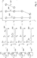
Werden in einem Füllstandmessgerät zyklische Messzyklen implementiert, so ergibt sich daraus eine Folge von empfangenen Echokurven, wie sie in
Das dargestellte Szenario zeigt die Verhältnisse beim Befüllen eines Behälters 201. Zu jedem der Zeitpunkte t0, t1, t2 und t3 wird ein Messzyklus des Füllstandmessgerätes 101 initiiert. Nach dem Empfangen der jeweiligen Echokurve 202, 203, 204, 205 wird diese mit bekannten Verfahren auf Echos hin untersucht. Um den Verlauf des Ortes oder der Position der einzelnen Echos über mehrere solcher Messzyklen hinweg verfolgen zu können, wird im weiteren Verfahrensablauf ein Tracking auf die gefundenen Echos durchgeführt.The scenario shown shows the conditions when filling a
Im vorliegenden Beispiel wird der Verlauf des Ortes der von der Antenne 104 selbst verursachten Echos e0, e3, e6 und e8 durch einen gemeinsamen Track T0 beschrieben. Zudem wird der Verlauf der vom Zuflussrohr 106 verursachten Echos e1 und e4 durch den zugehörigen Track T1 beschrieben. Der Verlauf der vom Füllgut 105 über mehrere Messzyklen hinweg verursachten Echos wird durch den Track T2 beschrieben, welcher aus den Echos e2, e5, e7 und c9 besteht.In the present example, the course of the location of the echoes e0, e3, e6 and e8 caused by the
Im Rahmen der Abarbeitung eines Trackingalgorithmus werden zum Zeitpunkt t0 die Tracks T0 und T2 initialisiert, und zu den Zeitpunkten t1, t2 und t3 fortlaufend erweitert. Weiterhin wird zum Zeitpunkt t0 der Track T1 initialisiert, und im Rahmen der Signalverarbeitungsprozedur zum Zeitpunkt t1 erweitert.As part of the processing of a tracking algorithm, tracks T0 and T2 are initialized at time t0 and continuously expanded at times t1, t2 and t3. Furthermore, track T1 is initialized at time t0 and expanded at time t1 as part of the signal processing procedure.
Die Darstellung des Verlaufes von Echos, welche eine gemeinsame Reflexionsstelle als Ursache haben, in Form eines Tracks ist in der Literatur beschrieben, und wird auch in anderen Bereichen, beispielsweise der Luftraumüberwachung, nutzbringend angewendet.The representation of the course of echoes, which is a common reflection point have as the cause, in the form of a track, is described in the literature and is also useful in other areas, for example airspace surveillance.
Die Zuordnung der aktuell erfassten Echos einer Echokurve zu den bereits in früheren Messzyklen erfassten Tracks wird im Wesentlichen dadurch erreicht, dass die Differenzen in Bezug auf den Ort und die Amplitude des Tracks und des jeweiligen Echos betrachtet werden, und nur Echos zu Tracks zugeordnet werden, wenn diese in etwa die gleiche Amplitude und Position wie die zuletzt bekannten korrespondierenden Kennwerte der Tracks aufweisen.The assignment of the currently recorded echoes of an echo curve to the tracks already recorded in earlier measurement cycles is essentially achieved by considering the differences in relation to the location and the amplitude of the track and the respective echo, and only assigning echoes to tracks, if they have approximately the same amplitude and position as the last known corresponding characteristic values of the tracks.
Anhand der Darstellung des zweiten Kurvenzugs 302 wird direkt ersichtlich, dass das Echo e15 der Füllgutoberfläche nahezu die gleiche Amplitude besitzt wie das Echo e14 des Zuflussrohres 106. Diese Konstellation hat nun zur Folge, dass ein konventionell durchgeführtes Trackingverfahren Schwierigkeiten mit der Zuordnung der Echos identischer Reflexionsstellen zu vorab bekannten Tracks hat. Entsprechend den oben skizzierten Ablaufschritten hat eine konventionelle Trackingeinrichtung 115 zum Zeitpunkt t t2 darüber zu entscheiden, ob das im Kurvenzug 303 identifizierte Echo e17 zum vorab bestehenden Track T3 305, T4 306 oder T5 307 zugeordnet werden soll. Aufgrund der großen Ortsdifferenz zwischen dem Track T3 und dem Echo e17 wird bei Abarbeitung konventioneller Trackingverfahren schnell klar, dass eine Zuordnung des Echos allenfalls zu Track T4 oder Track T5 erfolgen kann. In der einschlägigen Fachliteratur wird dieser Schritt einer "Vorabselektion" auch mit dem Begriff "Gating" umschrieben. Da die aktuellen Amplitudenwerte des Echos e14 (Track T4) und des Echos e15 (Track T5) nahezu identisch sind, kann die Entscheidung, zu welchem Track das Echo e17 zugeordnet werden soll, im vorliegenden Fall nur anhand der geringsten Ortsdifferenz zwischen dem Echo und dem jeweiligen Track gefällt werden. Infolgedessen werden das Echo e17 und nachfolgend auch das Echo e19 irrtümlicherweise zu Track T4 zugewiesen.On the basis of the representation of the
Da die Echos e17 und e19 jedoch von der Füllgutoberfläche verursacht worden sind, und der Track T4 die Echos des Zuflussrohres 106 gruppieren soll, liegt eine klassische Fehlzuordnung vor, welche die auf der Tracklistc aufbauenden weiteren Auswerteschritte massiv erschwert.However, since the echoes e17 and e19 were caused by the product surface, and the track T4 is intended to group the echoes of the
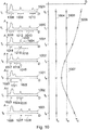
Zum Zeitpunkt t = t0 werden die Tracks T0, T1 und T2 initialisiert. Da diese Tracks allesamt nur ein einziges Echo aufweisen, und im vorliegenden Fall keine Dopplerauswertung erfolgen soll, kann zum entsprechenden Zeitpunkt keinerlei Aussage über die Mobilität der Tracks gemacht werden. Die Darstellung der Mobilitätswerte 401 zum Zeitpunkt t = t0 zeigt infolgedessen für alle Tracks eine Mobilität von 0 %. Es ist zu beachten, dass die Mobilität des Tracks T1 aus Gründen der Übersichtlichkeit hier nicht dargestellt ist. Zum Zeitpunkt t - t1 erkennt die Mobilitätsauswerteeinrichtung 116, dass sich der Track T2 im Zeitraum zwischen t0 und t1 bewegt hat, wohingegen der Track T0 im gleichen Zeitraum keinerlei Bewegung aufweist. Mit anderen Worten kann man sagen, dass die Mobilitätsauswerteeinrichtung (116) nach Abschluss des zum Zeitpunkt t=t1 initiierten Messzyklus des Füllstandmessgerätes feststellt, dass das Echo e3 des Tracks T0 eine Positionsverschiebung oder Bewegung von null oder nahezu null aufweist, und gleichzeitig das Echo e5 des Tracks T2 eine Positionsverschiebung oder Bewegung größer null aufweist. Es wird folglich die Mobilität M(T2) erhöht, wohingegen die Mobilität M(T0) erniedrigt wird. Die entsprechenden Stützstellen im Mobilitätsdiagramm (401) verdeutlichen zum Zeitpunkt t = t1, dass sich der Track T2 sicher bewegt (Mobilität > 0) wohingegen der Track T = T0 eine erwiesene Stationarität aufweist (Mobilität < 0). Mit anderen Worten kann man sagen, dass sich der Track T0 (und damit das ihm zugeordnete Echo e3) sicher nicht bewegt, da während dessen Verharren am Ort eine andere Bewegung erkannt worden ist. Zu den Zeitpunkten t - t2 und t = t3 verstärkt sich die gewonnene Erkenntnis nach obigem Schema. Es wird ersichtlich, dass die Mobilitätsanalyse durch eine fehlerhafte Trackliste gemäß dem Beispiel der
Die Erfindung stellt eine robuste Methode zum Tracking verschiedener Echos bereit. Insbesondere wird mit vorliegender Erfindung die Verbesserung bekannter Tracking-Algorithmen beim Überkreuzen zweier unterschiedlicher Tracks verbessert.The invention provides a robust method for tracking various echoes. In particular, the present invention improves the improvement of known tracking algorithms when crossing two different tracks.
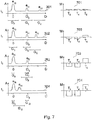
Zum Zeitpunkt t = t1 wird eine weitere Echokurve 302 erfasst. Die Tracks T3, T4 und T5 werden mit den Echos e13, e14 und e15 fortgesetzt. Weiterhin kann zu diesem Zeitpunkt eine erste Aussage über die Mobilität der Tracks gemacht werden. Das zugehörige Mobilitätsdiagramm 702 zeigt, dass Track T3 und T4 leicht stationäres Verhalten aufzeigen, wohingegen Track T5 sich bewegt. Mit anderen Worten kann man sagen, dass die Echos der Tracks T3, T4 oder auch die Tracks T3, T4 negative Mobilitätswerte aufweisen, wohingegen die Echos des Tracks T5 oder der Track T5 einen positiven Mobilitätswert aufweist. Die erfindungsgemäße Trackingeinrichtung berechnet die Breite der neuen Gates G3, G4 und G5 nun unter Verwendung der Mobilitätswerte der Tracks. Im vorliegenden Ausführungsbeispiel wird lediglich die negative Mobilität ausgewertet, was dazu führt, dass die Breite der Gates G3 und G4 im Vergleich zur Breite der Gates G0 und G1 verringert wird. Es mag auch möglich sein, die positive Mobilität zur Verbreiterung von Gates heranzuziehen.A
Zum Zeitpunkt t - t2 wird eine weitere Echokurve empfangen, deren Echos el6 und e17 zum Fortsetzen der T3 und T4 entsprechend der Darstellung aus
Es wird an dieser Stelle bereits ersichtlich, dass vom Gate G8 des Tracks T5 ein viel größerer Bereich erfasst wird als vom Gate G7 des Tracks T4. Mit vorliegender Maßnahme kann ein "Weg-Zuordnen" stationärer Tracks zu Echos mit größerer Positionsdifferenz wirksam verhindert werden.At this point it can already be seen that the gate G8 of the track T5 covers a much larger area than the gate G7 of the track T4. With the present measure, a "path assignment" of stationary tracks to echoes with larger ones can be done Position difference can be effectively prevented.
Das Ablaufdiagramm der
Das Trackingverfahren beginnt im Startzustand 801. Im Schritt 802 werden zunächst die Grenzen der Track-Gates ermittelt, woraufhin im Schritt 803 für diejenigen Echos, welche im Bereich des Track-Gates eines Tracks liegen, die Kosten der Zuordnung des jeweiligen Echos zum Track berechnet werden. Die Kosten einer Zuordnung geben ein Maß dafür an, wie gut ein Echo zu einem Track passt. Die Kosten können nach bekannten Verfahren berechnet werden, wobei insbesondere große Amplitudendifferenzen oder große Ortsdifferenzen zu hohen Kosten führen können.The tracking method begins in the
Im vorliegenden Ausführungsbeispiel der
Das Verfahren beginnt im Schritt 8020. Im Schritt 8021 wird zunächst der erste Track der Trackliste selektiert. Unter Verwendung der von der Mobilitätsauswerteeinrichtung 116 bereitgestellten Mobilitätsliste wird im Schritt 8022 nun überprüft, ob der Track sicher stationär ist, d.h. ob seine Mobilität identisch -100% ist. Falls dem so ist, wird die Aktualisierung der Gates ausgesetzt, und direkt zum nächsten Track übergegangen. Andernfalls wird im Schritt 8023 die neue Position des Gates unter Berücksichtigung der parametrierten oder fest einprogrammierten Gatebreiten ermittelt. Im Schritt 8024 wird überprüft, ob der Mobilitätswert des aktuellen Tracks zumindest auf stationäre Tendenzen hinweist. Ist dies der Fall, wird im Schritt S025 erfindungsgemäß die Breite des Gates nachträglich reduziert. Das Verfallen endet, wenn die Gates eines jeden Tracks berechnet wurden, im Endzustand 8028.The method begins in
Es sei an dieser Stelle darauf hingewiesen, dass die Berücksichtigung der Mobilitätswerte im Tracking durch Verringerung der Breite eines oder mehrerer Gates nur eine bevorzugte Ausführungsvariante darstellt. Weiterhin sind verschiedene andere Formen einer erfindungsgemäßen Verwendung von Mobilitätswenen innerhalb einer Trackingcinrichtung (602) denkbar. So kann beispielsweise die Berechnung der Gates auf klassische Art und Weise erfolgen, jedoch bei der Berechnung der Zuordnungskosten im Schritt (803) dafür gesorgt werden, dass die Mobilitätswerte einzelne Zuordnungen gezielt unterbinden. Auch ist es denkbar, während der Ermittlung des Zuordnungsvorschlags im Schritt 804 gezielt einzelne Zuweisungen zu verhindern. Weiterhin mag es auch möglich sein, erst bei der Zuordnung von Echos zu Tracks im Schritt (805) eine Berücksichtigung von Mobilitätswerten derart zu implementieren, dass Tracks mit erwiesener Stationarität nur mit auf den Ort oder die Position bezogen passenden Echos fortgesetzt werden.At this point, it should be pointed out that considering the mobility values in the tracking by reducing the width of one or more gates is only a preferred embodiment variant. Various other forms of use of mobility devices according to the invention within a tracking device (602) are also conceivable. For example, the calculation of the gates can be carried out in a classic manner, but the calculation of the assignment costs in step (803) ensures that the mobility values specifically prevent individual assignments. It is also conceivable to specifically prevent individual assignments during the determination of the assignment proposal in
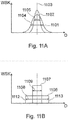
Die beiden Erwartungsfunktionen 1101 und 1102 sind beispielsweise Gauß-förmig und weisen verschiedene Breiten auf. So ist die flachere Erwartungsfunktion 1101 breiter (siehe Pfeil 1104) als die etwas steilere Erwartungsfunktion 1102 (siehe Pfeil 1105).The two
Als "Breite" der Erwartungsfunktion kann z. B. der Wert herangezogen werden, der die Breite der Funktion bei halber Höhe darstellt.As the "width" of the expectation function z. For example, use the value that represents the width of the function at half height.
Hier ist die Breite der Funktion gleichzusetzen mit dein Abstand des ansteigenden linken Schenkels 1112 zum abfallenden, rechten Schenkel 1113.Here the width of the function is to be equated with the distance of the rising
Die rechteckigen Erwartungsfunktionen 1106, 1107 können beispielsweise zur Durchführung eines klassischen oder eines erfindungsgemäßen Gating-Verfahrens verwendet werden.The rectangular expectation functions 1106, 1107 can be used, for example, to carry out a classic or an inventive gating method.
Andere Erwartungsfunktionen 1101, 1102 können beispielsweise zur erfindungsgemäßen Modifikation eines Verfahrens zur Kostenermittlung für die Zuordnung von Echos zu Tracks verwendet werden.Other expectation functions 1101, 1102 can be used, for example, to modify a method according to the invention for determining the cost of assigning echoes to tracks.
Ergänzend sei darauf hingewiesen, dass "umfassend" und "aufweisend" keine anderen Elemente oder Schritte ausschließt und "eine" oder "ein" keine Vielzahl ausschließt. Ferner sei daraufhingewiesen, dass Merkmale oder Schritte, die mit Verweis auf eines der obigen Ausführungsbeispiele beschrieben worden sind, auch in Kombination mit anderen Merkmalen oder Schritten anderer oben beschriebener Ausführungsbeispiele verwendet werden können. Bezugszeichen in den Ansprüchen sind nicht als Einschränkung anzusehen.In addition, it should be pointed out that “comprising” and “having” do not exclude other elements or steps, and “an” or “an” does not exclude a plurality. Furthermore, it should be pointed out that features or steps that have been described with reference to one of the above exemplary embodiments can also be used in combination with other features or steps of other exemplary embodiments described above. Reference signs in the claims are not to be viewed as a restriction.
Claims (10)
- A level measuring device (101) for determining mobility values of echoes of an echo curve and for carrying out a tracking method taking into account at least one of the mobility values, wherein a mobility value of an echo is a parameter for the movement of the echo, which is determined with consideration of simultaneously occurring movements or another change of at least one other echo, the level measuring device comprising:a calculation unit (108) for determining a first mobility value of a first echo of a first echo curve taking into account a positional displacement of the first echo and a positional displacement of a further echo of the first echo curve,wherein the calculation unit (108) is further configured to perform a tracking method for grouping echoes of temporally successive echo curves that are caused by identical reflection points;wherein the calculation unit (108) assigns a second echo of a second echo curve detected after the first echo curve to a certain track, taking into account at least the first mobility value;wherein the assignment of the second echo to the certain track is done using an expectancy function, with which a probability for the correct assignment of the second echo to the certain track can be calculated;wherein a width or a variance of the expectancy function is reduced if the positional displacement of the first echo of the first echo curve is zero but the positional displacement of the further echo of the first echo curve is not zero; andwherein the width or variance of the expectancy function is increased if the positional displacement of the first echo of the first echo curve is not zero.
- The level measuring device according to claim 1,
wherein the expectancy function is a window function. - The level measuring device according to any one of the preceding claims,
wherein the width or variance of the expectancy function is increased if the second echo falls short of a minimum distance to an adjacent echo of the second echo curve. - The level measuring device according to claim 3,
wherein the width or variance of the expectancy function is increased if the expectancy function overlaps with a corresponding expectancy function of the adjacent echo. - The level measuring device according to any one of the preceding claims,
wherein a mobility value of the second echo is reduced if the positional displacement of the first echo of the first echo curve is zero, but the positional displacement of the further echo of the first echo curve is not zero. - The level measuring device according to any one of the preceding claims,
wherein the expectancy functions allocated to the echoes of an initial echo curve that is acquired at the beginning of the tracking method and by means of which it is determined whether an echo of a subsequently acquired echo curve needs to be assigned to a certain track have identical widths or variances - Use of a level measuring device according to any one of the preceding claims for interfacial level measurements.
- A method for determining mobility values of echoes of an echo curve and for carrying out a tracking method taking into account at least one of the mobility values, wherein a mobility value of an echo is a parameter for the movement of the echo, which is determined with consideration of simultaneously occurring movements or another change of at least one other echo, the method comprising the stepsdetermining a first mobility value of a first echo of a first echo curve, taking into account a positional displacement of the first echo and a positional displacement of another echo of the first echo curve,performing a tracking method to group echoes of successive echo curves that are caused by identical reflection points;allocating a second echo of a second echo curve acquired after the first echo curve to a certain track, taking into account at least the first mobility value;wherein the allocation of the second echo to the certain track is done using an expectancy function, with which a probability for the correct allocation of the second echo to the certain track can be calculated;wherein a width or a variance of the expectancy function is reduced if the positional displacement of the first echo of the first echo curve is zero but the positional displacement of the further echo of the first echo curve is not zero; andwherein the width or variance of the expectancy function is increased if the positional disaplacement of the first echo of the first echo curve is not zero.
- A program element which, when executed on a processor of a level measuring device, instructs the processor to perform the method according to claim 8.
- A computer-readable medium having stored thereon a program element which, when executed on a processor of a level measuring device, instructs the processor to perform the method of claim 8.
Priority Applications (17)
| Application Number | Priority Date | Filing Date | Title |
|---|---|---|---|
| EP11176609.3A EP2554956B1 (en) | 2011-08-04 | 2011-08-04 | Tracking taking mobility into consideration |
| US13/552,189 US9086310B2 (en) | 2011-08-04 | 2012-07-18 | Tracking with consideration of mobility |
| PCT/EP2012/064742 WO2013017534A1 (en) | 2011-08-04 | 2012-07-26 | Linear relationship between tracks |
| PCT/EP2012/064740 WO2013017533A1 (en) | 2011-08-04 | 2012-07-26 | Tracking process taking into consideration a linear relationship |
| AU2012292174A AU2012292174B2 (en) | 2011-08-04 | 2012-07-26 | Tracking process taking into consideration a linear relationship |
| CN201280038603.XA CN103748440B (en) | 2011-08-04 | 2012-07-26 | It is tracked in the case of considering linear relationship |
| AU2012292175A AU2012292175B2 (en) | 2011-08-04 | 2012-07-26 | Linear relationship between tracks |
| CN201280038550.1A CN103733033B (en) | 2011-08-04 | 2012-07-26 | Linear relationship between track |
| HUE12740162A HUE044041T2 (en) | 2011-08-04 | 2012-07-26 | Linear relationship between tracks |
| BR112014001545-7A BR112014001545A2 (en) | 2011-08-04 | 2012-07-26 | linear relationship between tracks |
| EP12740161.0A EP2739945B1 (en) | 2011-08-04 | 2012-07-26 | Fill level measuring device and method for determining a functional correlation between different tracks |
| BR112014001164-8A BR112014001164A2 (en) | 2011-08-04 | 2012-07-26 | tracking, taking into account a linear relationship |
| EP12740162.8A EP2739946B1 (en) | 2011-08-04 | 2012-07-26 | Linear relationship between tracks |
| RU2014108062A RU2606456C2 (en) | 2011-08-04 | 2012-07-26 | Linear relationship between tracks |
| CN201210274123.5A CN102914346B (en) | 2011-08-04 | 2012-08-02 | Tracking in the case of consideration is ambulant |
| BR102012019557A BR102012019557A2 (en) | 2011-08-04 | 2012-08-03 | TRACKING WITH MOBILITY CONSIDERATION |
| RU2012133315/28A RU2600496C2 (en) | 2011-08-04 | 2012-08-03 | Tracking taking mobility into consideration |
Applications Claiming Priority (1)
| Application Number | Priority Date | Filing Date | Title |
|---|---|---|---|
| EP11176609.3A EP2554956B1 (en) | 2011-08-04 | 2011-08-04 | Tracking taking mobility into consideration |
Publications (2)
| Publication Number | Publication Date |
|---|---|
| EP2554956A1 EP2554956A1 (en) | 2013-02-06 |
| EP2554956B1 true EP2554956B1 (en) | 2020-07-29 |
Family
ID=44674223
Family Applications (1)
| Application Number | Title | Priority Date | Filing Date |
|---|---|---|---|
| EP11176609.3A Active EP2554956B1 (en) | 2011-08-04 | 2011-08-04 | Tracking taking mobility into consideration |
Country Status (5)
| Country | Link |
|---|---|
| US (1) | US9086310B2 (en) |
| EP (1) | EP2554956B1 (en) |
| CN (1) | CN102914346B (en) |
| BR (1) | BR102012019557A2 (en) |
| RU (1) | RU2600496C2 (en) |
Families Citing this family (11)
| Publication number | Priority date | Publication date | Assignee | Title |
|---|---|---|---|---|
| EP2584324B1 (en) * | 2011-10-17 | 2018-09-19 | VEGA Grieshaber KG | Fill level measuring device and method for determining a functional correlation between different tracks |
| DE102013213040B4 (en) * | 2013-07-03 | 2019-07-04 | Vega Grieshaber Kg | Transmission device for a measuring device and method for transmitting raw data with a transmission device |
| EP2869042B1 (en) * | 2013-11-04 | 2016-08-10 | VEGA Grieshaber KG | Model-based noise suppression for fill level measuring devices |
| US9778089B2 (en) * | 2014-06-30 | 2017-10-03 | Rosemount Tank Radar Ab | Multi-channel guided wave radar level gauge |
| US9618612B2 (en) * | 2015-02-13 | 2017-04-11 | Honeywell International Inc. | Marking tank obstructions using an electronic level gauge |
| EP3112821B1 (en) * | 2015-07-02 | 2018-05-02 | VEGA Grieshaber KG | Method and device for fill level measurement |
| DE102016100674B4 (en) * | 2016-01-15 | 2019-03-21 | Krohne Messtechnik Gmbh | Method for operating a non-contact ultrasonic or radar level gauge and non-contact ultrasonic or radar level gauge |
| JP6750567B2 (en) * | 2017-05-30 | 2020-09-02 | 株式会社Soken | Object detection device |
| EP3575817A1 (en) * | 2018-05-30 | 2019-12-04 | VEGA Grieshaber KG | Method for measuring fill levels |
| US11454716B2 (en) * | 2019-12-30 | 2022-09-27 | Woven Planet North America, Inc. | Systems and methods for adaptive gating in initialization of radar tracking |
| CN113108868A (en) * | 2021-04-19 | 2021-07-13 | 南宁师范大学 | Adaptive waveform retracing algorithm based on main wave crest |
Family Cites Families (24)
| Publication number | Priority date | Publication date | Assignee | Title |
|---|---|---|---|---|
| DE3337690A1 (en) | 1983-10-17 | 1985-04-25 | VEGA Grieshaber GmbH & Co, 7620 Wolfach | Method and device for measuring the filling level in a container by means of sound/ultrasonic waves |
| US4992998A (en) * | 1986-10-03 | 1991-02-12 | Federal Industries Industrial Group Inc. | Acoustic range finding system |
| US5157639A (en) * | 1990-09-04 | 1992-10-20 | Magnetrol International | Ultrasonic detector |
| DE4234300C2 (en) | 1992-10-12 | 1998-11-26 | Grieshaber Vega Kg | Level measurement method |
| JPH1164072A (en) * | 1997-08-20 | 1999-03-05 | Kaijo Corp | Interfacial level gauge |
| US5973637A (en) * | 1998-01-09 | 1999-10-26 | Endress + Hauser Gmbh + Co. | Partial probe mapping |
| US6504793B2 (en) * | 2000-09-11 | 2003-01-07 | Vega Grieshaber Kg | Method and device for range measurement |
| US6634228B2 (en) * | 2001-01-26 | 2003-10-21 | Endress + Hauser Gmbh + Co. Kg | Method of measuring level in a vessel |
| US6684919B2 (en) * | 2001-02-08 | 2004-02-03 | Vega Grieshaber Kg | Filling level measuring device and method for the non-contact determination of the filling level of a filling product in a receptacle |
| WO2004010093A1 (en) * | 2002-07-19 | 2004-01-29 | Vega Grieshaber Kg | Method and device for determining an expectancy range for a level echo and a spurious echo |
| SE0202491D0 (en) * | 2002-08-22 | 2002-08-22 | Saab Marine Electronics | Level gauging and alarm system |
| DE10260962A1 (en) * | 2002-12-20 | 2004-07-01 | Endress + Hauser Gmbh + Co. Kg | Level measuring device and method for level measurement according to the runtime principle |
| US6759976B1 (en) * | 2002-12-20 | 2004-07-06 | Saab Marine Electronics Ab | Method and apparatus for radar-based level gauging |
| DE10325267A1 (en) | 2003-06-03 | 2004-12-23 | Endress + Hauser Gmbh + Co. Kg | Arrangement and method for level measurement |
| EP1628119A3 (en) * | 2004-08-16 | 2012-07-25 | VEGA Grieshaber KG | Radar level measurement device with automatic echo signal determination |
| DE102004052110B4 (en) * | 2004-10-26 | 2018-08-23 | Endress+Hauser SE+Co. KG | Method for level measurement according to the transit time principle |
| SE0403165D0 (en) * | 2004-12-23 | 2004-12-23 | Saab Rosemount Tank Radar Ab | A radar level gauge system |
| US7355548B2 (en) * | 2005-09-01 | 2008-04-08 | Rosemount Tank Radar Ab | Processing of tank signal in radar level gauge system |
| US7467548B2 (en) * | 2005-10-14 | 2008-12-23 | Rosemount Tank Radar Ab | Radar level gauge system and coupling |
| DE102007031261A1 (en) | 2007-07-05 | 2009-01-08 | Universtität Regensburg | Luminescent metal complexes with bulky auxiliary ligands |
| HUE031382T2 (en) * | 2008-05-27 | 2017-07-28 | Grieshaber Vega Kg | Evaluation of an echo shape of filling level sensors |
| EP2148219B1 (en) | 2008-07-22 | 2011-10-12 | Siemens Milltronics Process Instruments Inc. | Processing of pulse-echo measurement signals |
| EP2226615B1 (en) * | 2009-03-02 | 2018-08-22 | VEGA Grieshaber KG | Measurement of fill levels by evaluating an echo curve |
| EP2366983B1 (en) * | 2010-03-17 | 2020-04-29 | VEGA Grieshaber KG | Mobility recognition in filling level measurement devices |
-
2011
- 2011-08-04 EP EP11176609.3A patent/EP2554956B1/en active Active
-
2012
- 2012-07-18 US US13/552,189 patent/US9086310B2/en active Active
- 2012-08-02 CN CN201210274123.5A patent/CN102914346B/en active Active
- 2012-08-03 BR BR102012019557A patent/BR102012019557A2/en not_active Application Discontinuation
- 2012-08-03 RU RU2012133315/28A patent/RU2600496C2/en active
Non-Patent Citations (1)
| Title |
|---|
| None * |
Also Published As
| Publication number | Publication date |
|---|---|
| CN102914346A (en) | 2013-02-06 |
| RU2012133315A (en) | 2014-02-10 |
| CN102914346B (en) | 2016-10-12 |
| RU2600496C2 (en) | 2016-10-20 |
| US9086310B2 (en) | 2015-07-21 |
| BR102012019557A2 (en) | 2014-02-18 |
| US20130035880A1 (en) | 2013-02-07 |
| EP2554956A1 (en) | 2013-02-06 |
Similar Documents
| Publication | Publication Date | Title |
|---|---|---|
| EP2554956B1 (en) | Tracking taking mobility into consideration | |
| EP2366983B1 (en) | Mobility recognition in filling level measurement devices | |
| EP2856086B1 (en) | Method for measuring fill-level in accordance with the travel time principle | |
| EP2226615B1 (en) | Measurement of fill levels by evaluating an echo curve | |
| EP2372318B1 (en) | Noise echo storage for container noises | |
| EP2667219B1 (en) | Detection of radar objects with a radar sensor of a motor vehicle | |
| EP2418465B1 (en) | Amplitude profiling in fill level measuring devices | |
| EP2365302B1 (en) | Measurement of the distance to at least one initial boundary area | |
| DE102006062606A1 (en) | Medium filling level determining and monitoring method for e.g. freely radiating microwave measuring device, involves adjusting shielding curve, evaluation curve and/or echo parameter based on change of position and/or amplitude of signals | |
| DE102010034263A1 (en) | Threshold value curve generating method for evaluation of signals of ultrasonic sensor, involves producing threshold value curve from nodes defined by temporal position and amplitude value that is determined based on spurious signal pattern | |
| EP2309235A1 (en) | Segment-based signal processing | |
| DE102010042525A1 (en) | Method for determining and monitoring the level of a medium in a container by means of a level gauge according to a transit time measurement method | |
| WO2015010814A1 (en) | Method for determining and monitoring the level of a medium in a container according to a runtime measurement method | |
| DE102016218093A1 (en) | Operating method for an ultrasonic sensor system, control device, ultrasonic sensor system and vehicle | |
| DE102004052110B4 (en) | Method for level measurement according to the transit time principle | |
| DE2554301A1 (en) | PROCEDURE FOR DETERMINING THE POSITION OF AN AIRPLANE AND WIRING ARRANGEMENT FOR PERFORMING THIS PROCEDURE | |
| DE102018200688A1 (en) | Method and device for operating an acoustic sensor | |
| DE102014114110A1 (en) | radar sensor | |
| DE19824267A1 (en) | Useful echo and clutter determination method for distance sensor, e.g. level detector | |
| DE102014215858A1 (en) | Method and device for detecting parking spaces extending between objects arranged laterally on a roadway edge | |
| EP2739946B1 (en) | Linear relationship between tracks | |
| EP2182380B1 (en) | Method for detecting peak overlays in a discrete spectrum of a location signal | |
| EP2584324B1 (en) | Fill level measuring device and method for determining a functional correlation between different tracks | |
| EP1742085B1 (en) | Method for object tracking in radar systems for motor vehicles | |
| DE10238896B4 (en) | Method for evaluating radar data |
Legal Events
| Date | Code | Title | Description |
|---|---|---|---|
| PUAI | Public reference made under article 153(3) epc to a published international application that has entered the european phase |
Free format text: ORIGINAL CODE: 0009012 |
|
| AK | Designated contracting states |
Kind code of ref document: A1 Designated state(s): AL AT BE BG CH CY CZ DE DK EE ES FI FR GB GR HR HU IE IS IT LI LT LU LV MC MK MT NL NO PL PT RO RS SE SI SK SM TR |
|
| AX | Request for extension of the european patent |
Extension state: BA ME |
|
| 17P | Request for examination filed |
Effective date: 20130703 |
|
| RBV | Designated contracting states (corrected) |
Designated state(s): AL AT BE BG CH CY CZ DE DK EE ES FI FR GB GR HR HU IE IS IT LI LT LU LV MC MK MT NL NO PL PT RO RS SE SI SK SM TR |
|
| STAA | Information on the status of an ep patent application or granted ep patent |
Free format text: STATUS: EXAMINATION IS IN PROGRESS |
|
| 17Q | First examination report despatched |
Effective date: 20181203 |
|
| GRAP | Despatch of communication of intention to grant a patent |
Free format text: ORIGINAL CODE: EPIDOSNIGR1 |
|
| STAA | Information on the status of an ep patent application or granted ep patent |
Free format text: STATUS: GRANT OF PATENT IS INTENDED |
|
| RIC1 | Information provided on ipc code assigned before grant |
Ipc: G01S 13/88 20060101ALN20200127BHEP Ipc: G01F 23/28 20060101AFI20200127BHEP Ipc: G01S 13/70 20060101ALI20200127BHEP Ipc: G01S 7/41 20060101ALI20200127BHEP |
|
| RIC1 | Information provided on ipc code assigned before grant |
Ipc: G01S 13/88 20060101ALN20200205BHEP Ipc: G01S 7/41 20060101ALI20200205BHEP Ipc: G01F 23/28 20060101AFI20200205BHEP Ipc: G01S 13/70 20060101ALI20200205BHEP |
|
| INTG | Intention to grant announced |
Effective date: 20200227 |
|
| GRAS | Grant fee paid |
Free format text: ORIGINAL CODE: EPIDOSNIGR3 |
|
| GRAA | (expected) grant |
Free format text: ORIGINAL CODE: 0009210 |
|
| STAA | Information on the status of an ep patent application or granted ep patent |
Free format text: STATUS: THE PATENT HAS BEEN GRANTED |
|
| AK | Designated contracting states |
Kind code of ref document: B1 Designated state(s): AL AT BE BG CH CY CZ DE DK EE ES FI FR GB GR HR HU IE IS IT LI LT LU LV MC MK MT NL NO PL PT RO RS SE SI SK SM TR |
|
| REG | Reference to a national code |
Ref country code: GB Ref legal event code: FG4D Free format text: NOT ENGLISH |
|
| REG | Reference to a national code |
Ref country code: CH Ref legal event code: EP |
|
| REG | Reference to a national code |
Ref country code: AT Ref legal event code: REF Ref document number: 1296331 Country of ref document: AT Kind code of ref document: T Effective date: 20200815 |
|
| REG | Reference to a national code |
Ref country code: IE Ref legal event code: FG4D Free format text: LANGUAGE OF EP DOCUMENT: GERMAN |
|
| REG | Reference to a national code |
Ref country code: DE Ref legal event code: R096 Ref document number: 502011016822 Country of ref document: DE |
|
| REG | Reference to a national code |
Ref country code: LT Ref legal event code: MG4D |
|
| REG | Reference to a national code |
Ref country code: NL Ref legal event code: MP Effective date: 20200729 |
|
| PG25 | Lapsed in a contracting state [announced via postgrant information from national office to epo] |
Ref country code: GR Free format text: LAPSE BECAUSE OF FAILURE TO SUBMIT A TRANSLATION OF THE DESCRIPTION OR TO PAY THE FEE WITHIN THE PRESCRIBED TIME-LIMIT Effective date: 20201030 Ref country code: LT Free format text: LAPSE BECAUSE OF FAILURE TO SUBMIT A TRANSLATION OF THE DESCRIPTION OR TO PAY THE FEE WITHIN THE PRESCRIBED TIME-LIMIT Effective date: 20200729 Ref country code: HR Free format text: LAPSE BECAUSE OF FAILURE TO SUBMIT A TRANSLATION OF THE DESCRIPTION OR TO PAY THE FEE WITHIN THE PRESCRIBED TIME-LIMIT Effective date: 20200729 Ref country code: BG Free format text: LAPSE BECAUSE OF FAILURE TO SUBMIT A TRANSLATION OF THE DESCRIPTION OR TO PAY THE FEE WITHIN THE PRESCRIBED TIME-LIMIT Effective date: 20201029 Ref country code: ES Free format text: LAPSE BECAUSE OF FAILURE TO SUBMIT A TRANSLATION OF THE DESCRIPTION OR TO PAY THE FEE WITHIN THE PRESCRIBED TIME-LIMIT Effective date: 20200729 Ref country code: NO Free format text: LAPSE BECAUSE OF FAILURE TO SUBMIT A TRANSLATION OF THE DESCRIPTION OR TO PAY THE FEE WITHIN THE PRESCRIBED TIME-LIMIT Effective date: 20201029 Ref country code: SE Free format text: LAPSE BECAUSE OF FAILURE TO SUBMIT A TRANSLATION OF THE DESCRIPTION OR TO PAY THE FEE WITHIN THE PRESCRIBED TIME-LIMIT Effective date: 20200729 Ref country code: PT Free format text: LAPSE BECAUSE OF FAILURE TO SUBMIT A TRANSLATION OF THE DESCRIPTION OR TO PAY THE FEE WITHIN THE PRESCRIBED TIME-LIMIT Effective date: 20201130 Ref country code: FI Free format text: LAPSE BECAUSE OF FAILURE TO SUBMIT A TRANSLATION OF THE DESCRIPTION OR TO PAY THE FEE WITHIN THE PRESCRIBED TIME-LIMIT Effective date: 20200729 |
|
| PG25 | Lapsed in a contracting state [announced via postgrant information from national office to epo] |
Ref country code: PL Free format text: LAPSE BECAUSE OF FAILURE TO SUBMIT A TRANSLATION OF THE DESCRIPTION OR TO PAY THE FEE WITHIN THE PRESCRIBED TIME-LIMIT Effective date: 20200729 Ref country code: LV Free format text: LAPSE BECAUSE OF FAILURE TO SUBMIT A TRANSLATION OF THE DESCRIPTION OR TO PAY THE FEE WITHIN THE PRESCRIBED TIME-LIMIT Effective date: 20200729 Ref country code: RS Free format text: LAPSE BECAUSE OF FAILURE TO SUBMIT A TRANSLATION OF THE DESCRIPTION OR TO PAY THE FEE WITHIN THE PRESCRIBED TIME-LIMIT Effective date: 20200729 Ref country code: IS Free format text: LAPSE BECAUSE OF FAILURE TO SUBMIT A TRANSLATION OF THE DESCRIPTION OR TO PAY THE FEE WITHIN THE PRESCRIBED TIME-LIMIT Effective date: 20201129 |
|
| PG25 | Lapsed in a contracting state [announced via postgrant information from national office to epo] |
Ref country code: NL Free format text: LAPSE BECAUSE OF FAILURE TO SUBMIT A TRANSLATION OF THE DESCRIPTION OR TO PAY THE FEE WITHIN THE PRESCRIBED TIME-LIMIT Effective date: 20200729 |
|
| REG | Reference to a national code |
Ref country code: CH Ref legal event code: PL |
|
| PG25 | Lapsed in a contracting state [announced via postgrant information from national office to epo] |
Ref country code: LI Free format text: LAPSE BECAUSE OF NON-PAYMENT OF DUE FEES Effective date: 20200831 Ref country code: IT Free format text: LAPSE BECAUSE OF FAILURE TO SUBMIT A TRANSLATION OF THE DESCRIPTION OR TO PAY THE FEE WITHIN THE PRESCRIBED TIME-LIMIT Effective date: 20200729 Ref country code: CZ Free format text: LAPSE BECAUSE OF FAILURE TO SUBMIT A TRANSLATION OF THE DESCRIPTION OR TO PAY THE FEE WITHIN THE PRESCRIBED TIME-LIMIT Effective date: 20200729 Ref country code: EE Free format text: LAPSE BECAUSE OF FAILURE TO SUBMIT A TRANSLATION OF THE DESCRIPTION OR TO PAY THE FEE WITHIN THE PRESCRIBED TIME-LIMIT Effective date: 20200729 Ref country code: DK Free format text: LAPSE BECAUSE OF FAILURE TO SUBMIT A TRANSLATION OF THE DESCRIPTION OR TO PAY THE FEE WITHIN THE PRESCRIBED TIME-LIMIT Effective date: 20200729 Ref country code: CH Free format text: LAPSE BECAUSE OF NON-PAYMENT OF DUE FEES Effective date: 20200831 Ref country code: MC Free format text: LAPSE BECAUSE OF FAILURE TO SUBMIT A TRANSLATION OF THE DESCRIPTION OR TO PAY THE FEE WITHIN THE PRESCRIBED TIME-LIMIT Effective date: 20200729 Ref country code: LU Free format text: LAPSE BECAUSE OF NON-PAYMENT OF DUE FEES Effective date: 20200804 Ref country code: RO Free format text: LAPSE BECAUSE OF FAILURE TO SUBMIT A TRANSLATION OF THE DESCRIPTION OR TO PAY THE FEE WITHIN THE PRESCRIBED TIME-LIMIT Effective date: 20200729 Ref country code: SM Free format text: LAPSE BECAUSE OF FAILURE TO SUBMIT A TRANSLATION OF THE DESCRIPTION OR TO PAY THE FEE WITHIN THE PRESCRIBED TIME-LIMIT Effective date: 20200729 |
|
| REG | Reference to a national code |
Ref country code: DE Ref legal event code: R097 Ref document number: 502011016822 Country of ref document: DE |
|
| REG | Reference to a national code |
Ref country code: BE Ref legal event code: MM Effective date: 20200831 |
|
| PG25 | Lapsed in a contracting state [announced via postgrant information from national office to epo] |
Ref country code: AL Free format text: LAPSE BECAUSE OF FAILURE TO SUBMIT A TRANSLATION OF THE DESCRIPTION OR TO PAY THE FEE WITHIN THE PRESCRIBED TIME-LIMIT Effective date: 20200729 |
|
| PLBE | No opposition filed within time limit |
Free format text: ORIGINAL CODE: 0009261 |
|
| STAA | Information on the status of an ep patent application or granted ep patent |
Free format text: STATUS: NO OPPOSITION FILED WITHIN TIME LIMIT |
|
| PG25 | Lapsed in a contracting state [announced via postgrant information from national office to epo] |
Ref country code: SK Free format text: LAPSE BECAUSE OF FAILURE TO SUBMIT A TRANSLATION OF THE DESCRIPTION OR TO PAY THE FEE WITHIN THE PRESCRIBED TIME-LIMIT Effective date: 20200729 |
|
| 26N | No opposition filed |
Effective date: 20210430 |
|
| PG25 | Lapsed in a contracting state [announced via postgrant information from national office to epo] |
Ref country code: FR Free format text: LAPSE BECAUSE OF NON-PAYMENT OF DUE FEES Effective date: 20200929 |
|
| PG25 | Lapsed in a contracting state [announced via postgrant information from national office to epo] |
Ref country code: SI Free format text: LAPSE BECAUSE OF FAILURE TO SUBMIT A TRANSLATION OF THE DESCRIPTION OR TO PAY THE FEE WITHIN THE PRESCRIBED TIME-LIMIT Effective date: 20200729 Ref country code: IE Free format text: LAPSE BECAUSE OF NON-PAYMENT OF DUE FEES Effective date: 20200804 Ref country code: BE Free format text: LAPSE BECAUSE OF NON-PAYMENT OF DUE FEES Effective date: 20200831 |
|
| REG | Reference to a national code |
Ref country code: AT Ref legal event code: MM01 Ref document number: 1296331 Country of ref document: AT Kind code of ref document: T Effective date: 20200804 |
|
| PG25 | Lapsed in a contracting state [announced via postgrant information from national office to epo] |
Ref country code: AT Free format text: LAPSE BECAUSE OF NON-PAYMENT OF DUE FEES Effective date: 20200804 |
|
| PG25 | Lapsed in a contracting state [announced via postgrant information from national office to epo] |
Ref country code: TR Free format text: LAPSE BECAUSE OF FAILURE TO SUBMIT A TRANSLATION OF THE DESCRIPTION OR TO PAY THE FEE WITHIN THE PRESCRIBED TIME-LIMIT Effective date: 20200729 Ref country code: MT Free format text: LAPSE BECAUSE OF FAILURE TO SUBMIT A TRANSLATION OF THE DESCRIPTION OR TO PAY THE FEE WITHIN THE PRESCRIBED TIME-LIMIT Effective date: 20200729 Ref country code: CY Free format text: LAPSE BECAUSE OF FAILURE TO SUBMIT A TRANSLATION OF THE DESCRIPTION OR TO PAY THE FEE WITHIN THE PRESCRIBED TIME-LIMIT Effective date: 20200729 |
|
| PG25 | Lapsed in a contracting state [announced via postgrant information from national office to epo] |
Ref country code: MK Free format text: LAPSE BECAUSE OF FAILURE TO SUBMIT A TRANSLATION OF THE DESCRIPTION OR TO PAY THE FEE WITHIN THE PRESCRIBED TIME-LIMIT Effective date: 20200729 |
|
| P01 | Opt-out of the competence of the unified patent court (upc) registered |
Effective date: 20230525 |
|
| PGFP | Annual fee paid to national office [announced via postgrant information from national office to epo] |
Ref country code: GB Payment date: 20230824 Year of fee payment: 13 |
|
| PGFP | Annual fee paid to national office [announced via postgrant information from national office to epo] |
Ref country code: DE Payment date: 20230822 Year of fee payment: 13 |