EP2554949A2 - Electromagnetic induction type absolute position measuring encoder - Google Patents
Electromagnetic induction type absolute position measuring encoder Download PDFInfo
- Publication number
- EP2554949A2 EP2554949A2 EP12178734A EP12178734A EP2554949A2 EP 2554949 A2 EP2554949 A2 EP 2554949A2 EP 12178734 A EP12178734 A EP 12178734A EP 12178734 A EP12178734 A EP 12178734A EP 2554949 A2 EP2554949 A2 EP 2554949A2
- Authority
- EP
- European Patent Office
- Prior art keywords
- scale
- coil
- coils
- absolute position
- electromagnetic induction
- Prior art date
- Legal status (The legal status is an assumption and is not a legal conclusion. Google has not performed a legal analysis and makes no representation as to the accuracy of the status listed.)
- Granted
Links
Images






Classifications
-
- G—PHYSICS
- G01—MEASURING; TESTING
- G01D—MEASURING NOT SPECIALLY ADAPTED FOR A SPECIFIC VARIABLE; ARRANGEMENTS FOR MEASURING TWO OR MORE VARIABLES NOT COVERED IN A SINGLE OTHER SUBCLASS; TARIFF METERING APPARATUS; MEASURING OR TESTING NOT OTHERWISE PROVIDED FOR
- G01D5/00—Mechanical means for transferring the output of a sensing member; Means for converting the output of a sensing member to another variable where the form or nature of the sensing member does not constrain the means for converting; Transducers not specially adapted for a specific variable
- G01D5/12—Mechanical means for transferring the output of a sensing member; Means for converting the output of a sensing member to another variable where the form or nature of the sensing member does not constrain the means for converting; Transducers not specially adapted for a specific variable using electric or magnetic means
- G01D5/14—Mechanical means for transferring the output of a sensing member; Means for converting the output of a sensing member to another variable where the form or nature of the sensing member does not constrain the means for converting; Transducers not specially adapted for a specific variable using electric or magnetic means influencing the magnitude of a current or voltage
- G01D5/20—Mechanical means for transferring the output of a sensing member; Means for converting the output of a sensing member to another variable where the form or nature of the sensing member does not constrain the means for converting; Transducers not specially adapted for a specific variable using electric or magnetic means influencing the magnitude of a current or voltage by varying inductance, e.g. by a movable armature
- G01D5/204—Mechanical means for transferring the output of a sensing member; Means for converting the output of a sensing member to another variable where the form or nature of the sensing member does not constrain the means for converting; Transducers not specially adapted for a specific variable using electric or magnetic means influencing the magnitude of a current or voltage by varying inductance, e.g. by a movable armature by influencing the mutual induction between two or more coils
- G01D5/2086—Mechanical means for transferring the output of a sensing member; Means for converting the output of a sensing member to another variable where the form or nature of the sensing member does not constrain the means for converting; Transducers not specially adapted for a specific variable using electric or magnetic means influencing the magnitude of a current or voltage by varying inductance, e.g. by a movable armature by influencing the mutual induction between two or more coils by movement of two or more coils with respect to two or more other coils
-
- G—PHYSICS
- G01—MEASURING; TESTING
- G01D—MEASURING NOT SPECIALLY ADAPTED FOR A SPECIFIC VARIABLE; ARRANGEMENTS FOR MEASURING TWO OR MORE VARIABLES NOT COVERED IN A SINGLE OTHER SUBCLASS; TARIFF METERING APPARATUS; MEASURING OR TESTING NOT OTHERWISE PROVIDED FOR
- G01D1/00—Measuring arrangements giving results other than momentary value of variable, of general application
-
- H—ELECTRICITY
- H01—ELECTRIC ELEMENTS
- H01F—MAGNETS; INDUCTANCES; TRANSFORMERS; SELECTION OF MATERIALS FOR THEIR MAGNETIC PROPERTIES
- H01F1/00—Magnets or magnetic bodies characterised by the magnetic materials therefor; Selection of materials for their magnetic properties
Definitions
- the present invention relates to an electromagnetic induction type absolute position measuring encoder, and, in particular, to an electromagnetic induction type absolute position measuring encoder suitable for use in a electronic digital caliper, an indicator, a linear scale, a micrometer, or the like, and capable of achieving a high precision in measurement due to an improvement in S/N ratio and/or capable of reducing a scale width and therefore an encoder width.
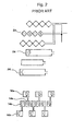
- Patent Literature 1 Japanese Patent Application Laid-Open No. Hei. 10-318781 (hereinafter referred to as Patent Literature 1) or in Japanese Patent Application Laid-Open No. 2003-121206 (hereinafter referred to as Patent Literature 2), there is known an electromagnetic induction type encoder as in FIG. 1 showing an example of Patent Literature 2.
- the electromagnetic induction type encoder includes: a large number of scale coils 14 and 16 arranged on a scale 10 along a measuring direction thereof; and transmitter coils 24 and 26 and receiver coils 20 and 22 arranged on a grid (also referred to as a slider) 12 capable of moving relative to the scale 10 in the measuring direction.
- a grid also referred to as a slider
- the electromagnetic induction type encoder detects an amount of relative movement between the scale 10 and the grid 12 from a flux change detected at the receiver coil via the scale coil when the transmitter coil is excited.
- reference numeral 28 denotes a transmission controller
- 30 denotes a receiving controller.
- the second receiver coils 22 are also arranged on the both sides of the second transmitter coil 26 as shown in FIG. 3 in addition to the configuration formed by the first transmitter coils 24 and the first receiver coil 20 shown in FIG. 2 .
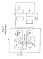
- Patent Literature 3 Japanese Patent Application Laid-Open No. 2009-186200 (hereinafter referred to as Patent Literature 3) that a plurality of sets of transmitter coils 24A and 24B, receiver coils 20A and 20B, and scale coils 14A and 14B are arranged symmetrically with respect to the center of the scale 10, and one of the scale coils symmetrically positioned with respect to the scale center (14A, for example) has a positional relationship shifted from the other one of the scale coils (14B, for example) by a 1/2 phase of a scale pitch ⁇ as shown in FIG. 4 of the present application corresponding to FIG. 6 in Patent Literature 3.
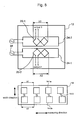
- FIG. 5 it is conceivable to enable absolute position measurement by placing two sets of a track including scale coils, a transmitter coil, and a receiver coil in a scale width direction (grid width direction) with different scale pitches of ⁇ 1 and ⁇ 2.
- the two sets includes a set formed by a transmitter coil 24-1 on the lower side of the figure, and scale coils 14-1a and a receiver coil 20-1 at the scale pitch ⁇ 1 on the upper side of the figure and a set formed by a transmitter coil 24-2 on the upper side of the figure, and scale coils 14-2a and a receiver coil 20-2 at the scale pitch ⁇ 2 on the lower side of the figure.
- reference numeral 14-3 denotes a coil for connecting the scale coil 14-1a with the scale coil 14-2a (referred to as a connecting coil).
- the receiver coil 20-1 (20-2) and the transmitter coil 24-1 (24-2) need to be placed at positions spaced apart from each other in order to reduce a direct crosstalk amount from the transmitter coil 24-1 or 24-2 to the receiver coil 20-2 or 20-1 on the grid 12.
- a length of the scale coils on the scale 10 (a length of the scale coil 14-1a + a length of the scale coil 14-2a + a length of the connecting coil 14-3) becomes long, resulting in attenuation of generated induced current Ia due to the impedance of the scale coil itself.
- a strong signal is difficult to be obtained.
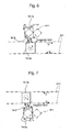
- FIG. 6 shows an operation of detecting the scale coils 14-1a at the scale pitch ⁇ 1 on the upper side of FIG. 5 by the receiver coil 20-1.
- the principle of the detection is essentially such that a magnetic field generated by the driving of the transmitter coil 24-1 with a driving current I D leads to the generation of the induced current Ia at the scale coil 14-2a and a magnetic field generated by the induced current Ia flowing through the scale coil 14-1a via the connecting coil 14-3 is then detected by the receiver coil 20-1.
- an induced current component Id in a direction opposite to that of the induced current Ia is generated at the scale coil 14-1a due to the magnetic field generated by the driving of the transmitter coil 24-1.
- the total induced current at the scale coil 14-1a becomes (Ia - Id), i.e., a reduction by an amount of Id.
- the induced current (Ia - Id) corresponding to a difference between the induced current component Ia via the scale coil 14-2a and the induced current component Id (in the direction opposite to that of Ia) generated by the magnetic field directly entered into the scale coil 14-1a from the transmitter coil 24-1 are generated at the scale coil 14-1a.
- FIG. 7 shows an operation of detecting the scale coil 14-2a on the lower side of FIG. 5 at the scale pitch ⁇ 2 by the receiver coil 20-2.
- the principle of the detection is essentially such that a magnetic field generated by the driving of the transmitter coil 24-2 with the driving current I D leads to the generation of the induced current Ia at the scale coil 14-1a and a magnetic field generated by the induced current Ia flowing through the scale coil 14-2a via the connecting coil 14-3 is then detected by the receiver coil 20-2.
- the induced current component Id in the direction opposite to that of the induced current Ia is generated at the scale coil 14-2a due to the magnetic field generated by the driving of the transmitter coil 24-2.
- the total induced current at the scale coil 14-2a becomes (Ia - Id), i.e., a reduction by an amount of Id.
- the induced current (Ia - Id) corresponding to a difference between the induced current component Ia via the scale coil 14-1a and the induced current component Id (in the direction opposite to that of Ia) generated by the magnetic field directly entered into the scale coil 14-2a from the transmitter coil 24-2 are generated at the scale coil 14-2a.
- a magnetic field generated by the induced current (Ia - Id) flowing through the scale coil 14-2a directly affects the receiver coil 20-1, and a crosstalk current component Ic (Ic1 at the left end side of the scale on the left side of FIG. 8 ) therefore flows through the receiver coil 20-1.
- the crosstalk current component generated at the receiver coil 20-1 varies depending on a position of the scale (Ic2 at the right end side of the scale on the right side of FIG. 8 ).
- the crosstalk current component which varies depending on a position in the measuring direction of the scale, is superimposed on a true position detection signal, thereby causing a problem of affecting a measurement accuracy (in particular, a wide range accuracy) over the entire length of the scale.
- the present invention has been made in order to solve the above-described problems in the conventional technique, and an object thereof is to improve a detection signal strength at a receiver coil by increasing an induced current in a scale coil when a transmitter coil is excited and thereby achieve a high measurement precision due to an improvement in S/N ratio and/or to downsize an encoder by reducing a scale width thereof and therefore an encoder width thereof, as well as to improve a wide range accuracy by reducing an induced current due to a crosstalk magnetic field.
- an electromagnetic induction type absolute position measuring encoder having two or more tracks
- the encoder including: two or more rows of scale coils, each of the rows including a large number of scale coils arranged on a scale along a measuring direction so as to have a scale pitch different from that of another row; a transmitter coil and a receiver coil arranged on a grid movable relative to the scale in the measuring direction so as to face the scale coils; and the track constituted by the scale coils, the transmitter coil and the receiver coil, and capable of measuring an absolute position of the grid with respect to the scale from a flux change detected by the receiver coil via the scale coils when the transmitter coil is excited, wherein at least one loop-shaped additional scale coil is added between the scale coils in at least one of the tracks.
- the scale coil (hereinafter, sometimes referred to as the "original scale coil”) may have a coil length twice or more as long as a coil length of the additional scale coil.
- the receiver coil may have a shape covering both of the original scale coil and the additional scale coil.
- the shape of the receiver coil may be a figure of eight with the top and bottom direction of the figure of eight coinciding with the measuring direction.
- a signal strength detected at the receiver coil may be increased to (Ia + Id)/(Ia - Id) times more than or equal to a signal strength obtained when no additional scale coil is added, where Id is an induced current component generated by a magnetic field directly entered into the original scale coil on the row to be measured from the transmitter coil, and Ia is an induced current component via the original scale coil on the other row.
- a line width of the additional scale coil may be adjusted so as to cancel out induced currents due to crosstalk magnetic fields from the scale coils to the receiver coil.
- a line width of the scale coil may be changed in accordance with a position in the measuring direction of the scale so as to cancel out induced currents due to crosstalk magnetic fields from the scale coils to the receiver coil.
- three or more rows of the scale coils may be provided.
- the scale coils may include first scale coils arranged at a scale pitch ⁇ 1, and second scale coils arranged at a scale pitch ⁇ 2 different from the scale pitch ⁇ 1 disposed on either side of the first scale coils, and further include an additional scale coil added only between the second scale coils disposed on either side of the first scale coils while no additional scale coil is added in the first scale coils at the center.
- the shape of the scale coil may be a rectangular frame shape.
- the present invention it is possible to increase the signal detection strength at the receiver coil when the transmitter coil is excited due to the induced current of the additional scale coil added between the original scale coils and to reduce the induced current due to the crosstalk magnetic field as compared to the configuration of FIG. 5 .
- scale coils 14-1 are configured by adding scale coils (referred to also as additional scale coils) 14-1b shown by broken lines in the figure between the originally-provided scale coil main bodies (referred to also as original scale coils or main body scale coils) 14-1a similar to those shown in FIG. 5 .
- scale coils 14-2 are configured by adding scale coils (referred to also as additional scale coils) 14-2b shown by broken lines in the figure between the originally-provided scale coil main bodies 14-2a (referred to also as original scale coils or main body scale coils) similar to those shown in FIG. 5 .
- an induced current Ib (in a direction opposite to that of the induced current (Ia - Id) at the main body scale coil 14-1a) by a magnetic field directly entered thereto from the transmitter coil 24-1.
- the induced current Id and the induced current Ib are compared to each other, (the induced current Id) ⁇ (the induced current Ib/2) holds true since the coil length of the scale coils (14-1a + 14-2a + 14-3) is more than or equal to double the coil length of the additional scale coil 14-1b.
- the receiver coil 20-1 has a coil shape in the figure of eight covering both of the main body coil 14-1a and the additional coil 14-1b with the top and bottom direction of the figure of eight coinciding with the measuring direction.
- a detection signal current at the receiver coil 20-1 is equal to that obtained by adding an induced signal current at the receiver coil 20-1 due to the current Ib of the additional scale coil 14-1b to an induced signal current at the receiver coil 20-1 due to the current (Ia - Id) of the main body scale coil 14-1a.
- a signal strength A detected at the receiver coil 20-1 is increased to (Ia + Id)/(Ia - Id) times more than or equal to a signal strength B obtained when no additional scale coil 14-1b is added.
- a ⁇ Ia - Id + Ib ⁇ Ia - Id + 2 ⁇ Id Ia + Id B ⁇ Ia - Id ⁇ A / B ⁇ Ia + Id / Ia - Id
- the induced current (Ia - Id) corresponding to a difference between the induced current component Ia via the main body scale coil 14-1a and the induced current component Id (in a direction opposite to that of Ia) generated by the magnetic field directly entered into the main body scale coil 14-2a from the transmitter coil 24-2 is generated at the main body scale coil 14-2a.
- the additional scale coil 14-2b there is generated the induced current Ib (in the direction opposite to that of the induced current (Ia - Id) at the main body scale coil 14-2a) by a magnetic field directly entered thereto from the transmitter coil 24-2.
- the induced current Id and the induced current Ib are compared to each other, (the induced current Id) ⁇ (the induced current Ib/2) holds true since the coil length of the scale coils (14-2a + 14-1a + 14-3) is more than or equal to double the coil length of the additional scale coil 14-2b.
- the receiver coil 20-2 has a coil shape in the figure of eight covering both of the main body scale coil 14-2a and the additional scale coil 14-2b with the top and bottom direction of the figure of eight coinciding with the measuring direction.
- a detection signal current at the receiver coil 20-2 is equal to that obtained by adding an induced signal current at the receiver coil 20-2 due to the current Ib of the additional scale coil 14-2b to an induced signal current at the receiver coil 20-2 due to the current (Ia - Id) of the main body scale coil 14-2a.
- a signal strength C detected at the receiver coil 20-2 is increased to (Ia + Id)/(Ia - Id) times more than or equal to the signal strength B obtained when no additional scale coil 14-2b is added as shown in the following expressions.
- C ⁇ Ia - Id + Ib ⁇ Ia - Id + 2 ⁇ Id Ia + Id B ⁇ Ia - Id ⁇ C / B ⁇ Ia + Id / Ia - Id
- the wide range accuracy can be improved due to the similar action as shown in FIG. 14 .
- the receiver coil has a shape in the figure of eight with the top and bottom direction of the figure of eight coinciding with the measuring direction, the induced currents due to the crosstalk magnetic fields are cancelled out each other. As a result, the induced current generated at the receiver coil 20-1 is substantially reduced, thereby further improving the wide range accuracy.
- the application of the present invention is not limited to those including two rows of tracks as shown in FIG. 10 .
- the present invention can also be applied, for example, to those including three rows of tracks in which the scale coils 14-2 at the scale pitch ⁇ 2 are arranged on the upper side and lower side of the scale coils 14-1 at the scale pitch ⁇ 1.
- the additional scale coils 14-2b are added only between the main body scale coils 14-2a in the scale coils 14-2 on the upper and lower sides, and no additional scale coils are added to the scale coils 14-1 arranged at the center. It is also possible to partially omit the addition of the scale coils in such a manner.
- the shape of the scale coil is described as a rectangular frame shape in any of the above-described embodiments, the shape of the scale coil is not limited thereto.
- it may be a plate shape having an electrode inside the rectangle or alternatively a plate shape obtained by removing the rectangular portion.
Landscapes
- Physics & Mathematics (AREA)
- General Physics & Mathematics (AREA)
- Transmission And Conversion Of Sensor Element Output (AREA)
Abstract
Description
- The present invention relates to an electromagnetic induction type absolute position measuring encoder, and, in particular, to an electromagnetic induction type absolute position measuring encoder suitable for use in a electronic digital caliper, an indicator, a linear scale, a micrometer, or the like, and capable of achieving a high precision in measurement due to an improvement in S/N ratio and/or capable of reducing a scale width and therefore an encoder width.
- As described in Japanese Patent Application Laid-Open No. Hei.
10-318781 2003-121206 FIG. 1 showing an example ofPatent Literature 2. The electromagnetic induction type encoder includes: a large number ofscale coils scale 10 along a measuring direction thereof; andtransmitter coils receiver coils scale 10 in the measuring direction. The electromagnetic induction type encoder detects an amount of relative movement between thescale 10 and thegrid 12 from a flux change detected at the receiver coil via the scale coil when the transmitter coil is excited. In this figure,reference numeral 28 denotes a transmission controller, and 30 denotes a receiving controller. - As shown in
FIG. 2 , in order to reduce an offset, which is an excess signal, in such an electromagnetic induction type encoder, an offset has been reduced by placing thereceiver coil 20 at a portion where magnetic fields generated by thetransmitter coils 24 are cancelled out to be net zero (a central portion between the transmitter coils on the both sides thereof in the example ofFIG. 2 ). Note that in Patent -
Literature 2, thesecond receiver coils 22 are also arranged on the both sides of thesecond transmitter coil 26 as shown inFIG. 3 in addition to the configuration formed by thefirst transmitter coils 24 and thefirst receiver coil 20 shown inFIG. 2 . - However, this configuration requires three rows of scale coils, and the line length of the scale coils therefore becomes long. Thus, there is the problem that the generated induced current is attenuated due to an impedance of the scale coil itself and it is therefore difficult to obtain a strong signal.
- In order to solve such a problem, the present applicant has suggested in Japanese Patent Application Laid-Open No.
2009-186200 transmitter coils receiver coils scale coils scale 10, and one of the scale coils symmetrically positioned with respect to the scale center (14A, for example) has a positional relationship shifted from the other one of the scale coils (14B, for example) by a 1/2 phase of a scale pitch λ as shown inFIG. 4 of the present application corresponding toFIG. 6 in Patent Literature 3. - Furthermore, as shown in
FIG. 5 , it is conceivable to enable absolute position measurement by placing two sets of a track including scale coils, a transmitter coil, and a receiver coil in a scale width direction (grid width direction) with different scale pitches of λ1 and λ2. The two sets includes a set formed by a transmitter coil 24-1 on the lower side of the figure, and scale coils 14-1a and a receiver coil 20-1 at the scale pitch λ1 on the upper side of the figure and a set formed by a transmitter coil 24-2 on the upper side of the figure, and scale coils 14-2a and a receiver coil 20-2 at the scale pitch λ2 on the lower side of the figure. In this figure, reference numeral 14-3 denotes a coil for connecting the scale coil 14-1a with the scale coil 14-2a (referred to as a connecting coil). - With the configuration of
FIG. 5 , however, the receiver coil 20-1 (20-2) and the transmitter coil 24-1 (24-2) need to be placed at positions spaced apart from each other in order to reduce a direct crosstalk amount from the transmitter coil 24-1 or 24-2 to the receiver coil 20-2 or 20-1 on thegrid 12. Thus, a length of the scale coils on the scale 10 (a length of the scale coil 14-1a + a length of the scale coil 14-2a + a length of the connecting coil 14-3) becomes long, resulting in attenuation of generated induced current Ia due to the impedance of the scale coil itself. Thus, there is the problem that a strong signal is difficult to be obtained. - Moreover, if it is attempted with the configuration of
FIG. 5 to reduce the encoder width, for example, by reducing a space between the scale coils 14-1a and 14-2a, a magnetic field generated by the driving of the transmitter coil also directly affects the scale coil directly facing the receiver coil. As a result, there is generated an induced current component in a direction opposite to that of the normal induced current flowing through the scale coil, thereby reducing an induced current generated in the scale coil. This leads to the problem of a decrease in signals detected at the receiver coil. - A description thereof will be given below.
-
FIG. 6 shows an operation of detecting the scale coils 14-1a at the scale pitch λ1 on the upper side ofFIG. 5 by the receiver coil 20-1. As shown in the figure, the principle of the detection is essentially such that a magnetic field generated by the driving of the transmitter coil 24-1 with a driving current ID leads to the generation of the induced current Ia at the scale coil 14-2a and a magnetic field generated by the induced current Ia flowing through the scale coil 14-1a via the connecting coil 14-3 is then detected by the receiver coil 20-1. As the scale coil 14-1a approaches to the transmitter coil 24-1, however, an induced current component Id in a direction opposite to that of the induced current Ia is generated at the scale coil 14-1a due to the magnetic field generated by the driving of the transmitter coil 24-1. As a result, the total induced current at the scale coil 14-1a becomes (Ia - Id), i.e., a reduction by an amount of Id. In other words, the induced current (Ia - Id) corresponding to a difference between the induced current component Ia via the scale coil 14-2a and the induced current component Id (in the direction opposite to that of Ia) generated by the magnetic field directly entered into the scale coil 14-1a from the transmitter coil 24-1 are generated at the scale coil 14-1a. - On the other hand,
FIG. 7 shows an operation of detecting the scale coil 14-2a on the lower side ofFIG. 5 at the scale pitch λ2 by the receiver coil 20-2. As shown in this figure, the principle of the detection is essentially such that a magnetic field generated by the driving of the transmitter coil 24-2 with the driving current ID leads to the generation of the induced current Ia at the scale coil 14-1a and a magnetic field generated by the induced current Ia flowing through the scale coil 14-2a via the connecting coil 14-3 is then detected by the receiver coil 20-2. As the scale coil 14-2a approaches to the transmitter coil 24-2, however, the induced current component Id in the direction opposite to that of the induced current Ia is generated at the scale coil 14-2a due to the magnetic field generated by the driving of the transmitter coil 24-2. As a result, the total induced current at the scale coil 14-2a becomes (Ia - Id), i.e., a reduction by an amount of Id. In other words, the induced current (Ia - Id) corresponding to a difference between the induced current component Ia via the scale coil 14-1a and the induced current component Id (in the direction opposite to that of Ia) generated by the magnetic field directly entered into the scale coil 14-2a from the transmitter coil 24-2 are generated at the scale coil 14-2a. - Further, if it is attempted with the configuration of
FIG. 5 to reduce the encoder width, for example, by reducing the space between the scale coils 14-1a and 14-2a, the following disadvantage also occurs. - In other words, as shown in
FIG. 8 , a magnetic field generated by the induced current (Ia - Id) flowing through the scale coil 14-2a directly affects the receiver coil 20-1, and a crosstalk current component Ic (Ic1 at the left end side of the scale on the left side ofFIG. 8 ) therefore flows through the receiver coil 20-1. - In a case of the scale having the two-track configuration with different scale pitches as shown in
FIG. 5 , the crosstalk current component generated at the receiver coil 20-1 varies depending on a position of the scale (Ic2 at the right end side of the scale on the right side ofFIG. 8 ). Thus, the crosstalk current component, which varies depending on a position in the measuring direction of the scale, is superimposed on a true position detection signal, thereby causing a problem of affecting a measurement accuracy (in particular, a wide range accuracy) over the entire length of the scale. - In the scale of
FIG. 5 having tracks with the scale pitch λ1 and the scale pitch λ2 (λ1 < λ2 in this example) respectively, if the scale at the scale pitch λ1 is detected (measured) by the receiver coil 20-1 as in the example ofFIG. 8 , the wide range accuracy thereof has errors in a plus direction as shown inFIG. 9 due to the effect of the scale at the scale pitch λ2. If the scale at the scale pitch λ2 is detected (measured) by the receiver coil 20-2, on the other hand, the wide range accuracy thereof has errors in a minus direction as shown inFIG. 9 due to a cause similar to that described above, i.e., the effect of the scale at the scale pitch λ1. - The present invention has been made in order to solve the above-described problems in the conventional technique, and an object thereof is to improve a detection signal strength at a receiver coil by increasing an induced current in a scale coil when a transmitter coil is excited and thereby achieve a high measurement precision due to an improvement in S/N ratio and/or to downsize an encoder by reducing a scale width thereof and therefore an encoder width thereof, as well as to improve a wide range accuracy by reducing an induced current due to a crosstalk magnetic field.
- The present invention solves the above-described problems by an electromagnetic induction type absolute position measuring encoder having two or more tracks, the encoder including: two or more rows of scale coils, each of the rows including a large number of scale coils arranged on a scale along a measuring direction so as to have a scale pitch different from that of another row; a transmitter coil and a receiver coil arranged on a grid movable relative to the scale in the measuring direction so as to face the scale coils; and the track constituted by the scale coils, the transmitter coil and the receiver coil, and capable of measuring an absolute position of the grid with respect to the scale from a flux change detected by the receiver coil via the scale coils when the transmitter coil is excited, wherein at least one loop-shaped additional scale coil is added between the scale coils in at least one of the tracks.
- Here, the scale coil (hereinafter, sometimes referred to as the "original scale coil") may have a coil length twice or more as long as a coil length of the additional scale coil.
- Furthermore, the receiver coil may have a shape covering both of the original scale coil and the additional scale coil.
- Furthermore, the shape of the receiver coil may be a figure of eight with the top and bottom direction of the figure of eight coinciding with the measuring direction.
- Furthermore, a signal strength detected at the receiver coil may be increased to (Ia + Id)/(Ia - Id) times more than or equal to a signal strength obtained when no additional scale coil is added, where Id is an induced current component generated by a magnetic field directly entered into the original scale coil on the row to be measured from the transmitter coil, and Ia is an induced current component via the original scale coil on the other row.
- Furthermore, a line width of the additional scale coil may be adjusted so as to cancel out induced currents due to crosstalk magnetic fields from the scale coils to the receiver coil.
- Furthermore, a line width of the scale coil may be changed in accordance with a position in the measuring direction of the scale so as to cancel out induced currents due to crosstalk magnetic fields from the scale coils to the receiver coil.
- Furthermore, three or more rows of the scale coils may be provided.
- Furthermore, the scale coils may include first scale coils arranged at a scale pitch λ1, and second scale coils arranged at a scale pitch λ2 different from the scale pitch λ1 disposed on either side of the first scale coils, and further include an additional scale coil added only between the second scale coils disposed on either side of the first scale coils while no additional scale coil is added in the first scale coils at the center.
- Furthermore, the shape of the scale coil may be a rectangular frame shape.
- According to the present invention, it is possible to increase the signal detection strength at the receiver coil when the transmitter coil is excited due to the induced current of the additional scale coil added between the original scale coils and to reduce the induced current due to the crosstalk magnetic field as compared to the configuration of
FIG. 5 . Therefore, there are provided advantageous effects such as (1) it becomes possible to reduce a space between two or more tracks and thus to downsize an encoder by reducing a scale width and accordingly an encoder width, (2) a measurement accuracy can be improved by an improvement in S/N ratio, (3) a gap between a grid and a scale can be widened, (4) it becomes possible to reduce a width of a scale coil and thus to downsize an encoder by reducing a scale width and accordingly an encoder width, and (5) a wide range accuracy can be improved by reducing an effect of a crosstalk magnetic field. - These and other novel features and advantages of the present invention will become apparent from the following detailed description of preferred embodiments.
- The preferred embodiments will be described with reference to the drawings, wherein like elements have been denoted throughout the figures with like reference numerals, and wherein:
-
FIG. 1 is a perspective view showing the entire configuration of a conventional electromagnetic induction type encoder described inPatent Literature 2; -
FIG. 2 is a plan view similarly showing an arrangement and a first function of coils on a grid; -
FIG. 3 is a plan view similarly showing an arrangement and a second function of coils on a grid; -
FIG. 4 is a plan view showing a grid and a scale of a conventional electromagnetic induction type encoder described in Patent Literature 3; -
FIG.5 is a plan view of a grid and a scale showing a basic configuration of an electromagnetic induction type absolute position measuring encoder under consideration by the present inventor; -
FIG. 6 is a plan view of a main section illustrating how a transmitter coil on a lower side ofFIG. 5 is driven to perform detection at a receiver coil on an upper side thereof; -
FIG. 7 is a plan view of a main section illustrating how a transmitter coil on the upper side ofFIG. 5 is driven to perform detection at a receiver coil on the lower side thereof; -
FIG. 8 is a plan view of a main section illustrating occurrences of induced currents due to crosstalk magnetic fields in a conventional example; -
FIG. 9 is a graph similarly showing an example of wide range errors; -
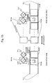
FIG. 10 is a plan view of a scale according to a first embodiment of the present invention; -
FIG. 11 is a plan view of a main section illustrating how a transmitter coil on a lower side ofFIG. 10 is driven to perform detection at a receiver coil on an upper side thereof; -
FIG. 12 is a plan view of a main section illustrating how a transmitter coil on the upper side ofFIG. 10 is driven to perform detection at a receiver coil on the lower side thereof; -
FIG. 13 is a plan view of a main section illustrating occurrences of induced currents due to crosstalk magnetic fields in the first embodiment; -
FIG. 14 is a graph similarly showing an example of wide range errors; -
FIG. 15 is a plan view of a scale similarly showing a modification; -
FIG. 16 is a plan view of a scale similarly showing another modification; and -
FIG. 17 is a plan view of a scale according to a second embodiment of the present invention. - Embodiments of the present invention will be described below in detail with reference to the drawings.
- As shown in
FIG. 10 , according to the first embodiment of the present invention, scale coils 14-1 are configured by adding scale coils (referred to also as additional scale coils) 14-1b shown by broken lines in the figure between the originally-provided scale coil main bodies (referred to also as original scale coils or main body scale coils) 14-1a similar to those shown inFIG. 5 . Similarly, scale coils 14-2 are configured by adding scale coils (referred to also as additional scale coils) 14-2b shown by broken lines in the figure between the originally-provided scale coil main bodies 14-2a (referred to also as original scale coils or main body scale coils) similar to those shown inFIG. 5 . - A reason why a signal strength detected at the receiver coil is increased with the above-described configuration even when an encoder width is reduced, for example, by reducing a space between the scale coils 14-1a and 14-2a will now be described below.
- First, as shown in
FIG. 11 , when the scale coils 14-1 at the scale pitch λ1 positioned on the upper side ofFIG. 10 are detected by the receiver coil 20-1, due to a magnetic field generated by the driving of the transmitter coil 24-1 with the driving current ID, the induced current (Ia - Id) corresponding to a difference between the induced current component Ia via the main body scale coil 14-2a and the induced current component Id (in a direction opposite to that of Ia) generated by the magnetic field directly entered into the main body scale coil 14-1a from the transmitter coil 24-1 is generated at the main body scale coil 14-1a. Also, at the additional coil 14-1b, there is generated an induced current Ib (in a direction opposite to that of the induced current (Ia - Id) at the main body scale coil 14-1a) by a magnetic field directly entered thereto from the transmitter coil 24-1. When the magnitudes of the induced current Id and the induced current Ib are compared to each other, (the induced current Id) < (the induced current Ib/2) holds true since the coil length of the scale coils (14-1a + 14-2a + 14-3) is more than or equal to double the coil length of the additional scale coil 14-1b. - The receiver coil 20-1 has a coil shape in the figure of eight covering both of the main body coil 14-1a and the additional coil 14-1b with the top and bottom direction of the figure of eight coinciding with the measuring direction. Thus, a detection signal current at the receiver coil 20-1 is equal to that obtained by adding an induced signal current at the receiver coil 20-1 due to the current Ib of the additional scale coil 14-1b to an induced signal current at the receiver coil 20-1 due to the current (Ia - Id) of the main body scale coil 14-1a.
- Thus, as shown in the following expressions, a signal strength A detected at the receiver coil 20-1 is increased to (Ia + Id)/(Ia - Id) times more than or equal to a signal strength B obtained when no additional scale coil 14-1b is added.



- As shown in
FIG. 12 , when the scale coils 14-2 at the scale pitch λ2 positioned on the lower side ofFIG. 10 are detected by the receiver coil 20-2, on the other hand, due to a magnetic field generated by the driving of the transmitter coil 24-2 with the driving current ID, the induced current (Ia - Id) corresponding to a difference between the induced current component Ia via the main body scale coil 14-1a and the induced current component Id (in a direction opposite to that of Ia) generated by the magnetic field directly entered into the main body scale coil 14-2a from the transmitter coil 24-2 is generated at the main body scale coil 14-2a. Also, at the additional scale coil 14-2b, there is generated the induced current Ib (in the direction opposite to that of the induced current (Ia - Id) at the main body scale coil 14-2a) by a magnetic field directly entered thereto from the transmitter coil 24-2. When the magnitudes of the induced current Id and the induced current Ib are compared to each other, (the induced current Id) < (the induced current Ib/2) holds true since the coil length of the scale coils (14-2a + 14-1a + 14-3) is more than or equal to double the coil length of the additional scale coil 14-2b. - The receiver coil 20-2 has a coil shape in the figure of eight covering both of the main body scale coil 14-2a and the additional scale coil 14-2b with the top and bottom direction of the figure of eight coinciding with the measuring direction. Thus, a detection signal current at the receiver coil 20-2 is equal to that obtained by adding an induced signal current at the receiver coil 20-2 due to the current Ib of the additional scale coil 14-2b to an induced signal current at the receiver coil 20-2 due to the current (Ia - Id) of the main body scale coil 14-2a.
- Thus, in a similar manner as that described above, a signal strength C detected at the receiver coil 20-2 is increased to (Ia + Id)/(Ia - Id) times more than or equal to the signal strength B obtained when no additional scale coil 14-2b is added as shown in the following expressions.


- Further, with the addition of the loop-shaped scale coils (14-Ib and 14-2b), as shown in
FIG. 13 , when the scale coils 14-1 at the scale pitch λ1 on the upper side ofFIG. 10 are detected by the receiver coil 20-1, crosstalk magnetic fields from the scale coils 14-2 to the receiver coil 20-1 become substantially uniform without depending on a position of the scale in the measuring direction. As a result, a difference between the induced currents due to the crosstalk magnetic fields becomes small (Ic1 ≈ Ic2), thereby improving the wide range accuracy as shown inFIG. 14 . Also when the scale coils 14-2 at the scale pitch λ2 on the lower side ofFIG. 10 are detected by the receiver coil 20-2, the wide range accuracy can be improved due to the similar action as shown inFIG. 14 . In particular, when the receiver coil has a shape in the figure of eight with the top and bottom direction of the figure of eight coinciding with the measuring direction, the induced currents due to the crosstalk magnetic fields are cancelled out each other. As a result, the induced current generated at the receiver coil 20-1 is substantially reduced, thereby further improving the wide range accuracy. - Further, as illustrated in
FIG. 15 by way of example, the above-described induced currents can be completely cancelled out each other by adjusting a line width of the added scale coils (14-1b and 14-2b). Alternatively, as illustrated inFIG. 16 by way of example, a line width of the scale coil can be changed in accordance with the position of the scale in the measuring direction so as to satisfy Ic1 = Ic2, thereby achieving a higher degree of accuracy. - Further, the application of the present invention is not limited to those including two rows of tracks as shown in
FIG. 10 . As in the second embodiment shown inFIG. 17 , the present invention can also be applied, for example, to those including three rows of tracks in which the scale coils 14-2 at the scale pitch λ2 are arranged on the upper side and lower side of the scale coils 14-1 at the scale pitch λ1. - In the second embodiment, the additional scale coils 14-2b are added only between the main body scale coils 14-2a in the scale coils 14-2 on the upper and lower sides, and no additional scale coils are added to the scale coils 14-1 arranged at the center. It is also possible to partially omit the addition of the scale coils in such a manner.
- Although the shape of the scale coil is described as a rectangular frame shape in any of the above-described embodiments, the shape of the scale coil is not limited thereto. For example, it may be a plate shape having an electrode inside the rectangle or alternatively a plate shape obtained by removing the rectangular portion.
- Features, components and specific details of the structures of the above-described embodiments may be exchanged or combined to form further embodiments optimized for the respective application. As far as those modifications are readily apparent for an expert skilled in the art they shall be disclosed implicitly by the above description without specifying explicitly every possible combination, for the sake of conciseness of the present description.
Claims (10)
- An electromagnetic induction type absolute position measuring encoder having two or more tracks, the encoder comprising:two or more rows of scale coils (14-1), each of the rows including a large number of scale coils (14-1) arranged on a scale along a measuring direction so as to have a scale pitch (λ1; λ2) different from that of another row;a transmitter coil (24-1) and a receiver coil (20-1) arranged on a grid movable relative to the scale in the measuring direction so as to face the scale coils (14-1); andthe track constituted by the scale coils (14-1), the transmitter coil (24-1) and the receiver coil (20-1),the encoder being capable of measuring an absolute position of the grid with respect to the scale from a flux change detected by the receiver coil (20-1) via the scale coils (14-1) when the transmitter coil (24-1) is excited, whereinat least one loop-shaped additional scale coil (14-1b) is added between the scale coils (14-1) in at least one of the tracks.
- The electromagnetic induction type absolute position measuring encoder according to claim 1, wherein the scale coil (14-1) has a coil length twice or more as long as a coil length of the additional scale coil (14-1b).
- The electromagnetic induction type absolute position measuring encoder according to claim 1 or 2, wherein the receiver coil (20-1) has a shape covering both of the original scale coil (14-1) and the additional scale coil (14-1b).
- The electromagnetic induction type absolute position measuring encoder according to at least one of claims 1 to 3, wherein the shape of the receiver coil (20-1) is a figure of eight with the top and bottom direction of the figure of eight coinciding with the measuring direction.
- l The electromagnetic induction type absolute position measuring encoder according to at least one of claims 1 to 4, wherein a signal strength detected at the receiver coil (20-1) is increased to (Ia + Id)/(Ia - Id) times more than or equal to a signal strength obtained when no additional scale coil (14-1b) is added, where Id is an induced current component generated by a magnetic field directly entered into the original scale coil (14-1) on the row to be measured from the transmitter coil (24-1), and Ia is an induced current component via the original scale coil (14-1) on the other row.
- The electromagnetic induction type absolute position measuring encoder according to at least one of claims 1 to 5, wherein a line width of the additional scale coil (14-1b) is adjusted so as to cancel out induced currents due to crosstalk magnetic fields from the scale coils (14-1) to the receiver coil (20-1).
- The electromagnetic induction type absolute position measuring encoder according to at least one of claims 1 to 5, wherein a line width of the scale coil (14-1) is changed in accordance with a position in the measuring direction of the scale so as to cancel out induced currents due to crosstalk magnetic fields from the scale coils (14-1) to the receiver coil (20-1).
- The electromagnetic induction type absolute position measuring encoder according to at least one of claims 1 to 7, wherein three or more rows of the scale coils (14-1) are provided.
- The electromagnetic induction type absolute position measuring encoder according to at least one of claims 1 to 8, wherein the scale coils (14-1) include first scale coils arranged at a scale pitch (λ1), and second scale coils arranged at a scale pitch (λ2) different from the scale pitch (λ1) disposed on either side of the first scale coils, and further include an additional scale coil (14-1b) added only between the second scale coils disposed on either side of the first scale coils while no additional scale coil (14-1b) is added in the first scale coils at the center.
- The electromagnetic induction type absolute position measuring encoder according to at least one of claims 1 to 9, wherein the shape of the scale coil (14-1) is a rectangular frame shape.
Applications Claiming Priority (1)
| Application Number | Priority Date | Filing Date | Title |
|---|---|---|---|
| JP2011170510A JP5809479B2 (en) | 2011-08-03 | 2011-08-03 | Electromagnetic induction type absolute position measurement encoder |
Publications (3)
| Publication Number | Publication Date |
|---|---|
| EP2554949A2 true EP2554949A2 (en) | 2013-02-06 |
| EP2554949A3 EP2554949A3 (en) | 2017-08-30 |
| EP2554949B1 EP2554949B1 (en) | 2018-12-19 |
Family
ID=46982381
Family Applications (1)
| Application Number | Title | Priority Date | Filing Date |
|---|---|---|---|
| EP12178734.5A Active EP2554949B1 (en) | 2011-08-03 | 2012-07-31 | Electromagnetic induction type absolute position measuring encoder |
Country Status (4)
| Country | Link |
|---|---|
| US (1) | US8847583B2 (en) |
| EP (1) | EP2554949B1 (en) |
| JP (1) | JP5809479B2 (en) |
| CN (1) | CN102914245B (en) |
Cited By (1)
| Publication number | Priority date | Publication date | Assignee | Title |
|---|---|---|---|---|
| EP2851655A1 (en) * | 2013-09-19 | 2015-03-25 | Dr. Johannes Heidenhain GmbH | Inductive position measurement device |
Families Citing this family (24)
| Publication number | Priority date | Publication date | Assignee | Title |
|---|---|---|---|---|
| JP6297287B2 (en) * | 2013-09-18 | 2018-03-20 | 株式会社ミツトヨ | Rotary encoder and micrometer provided with the same |
| CN103471494B (en) * | 2013-09-18 | 2016-09-14 | 颜福才 | High-precision pure digital position sensor |
| US10775199B2 (en) * | 2016-08-24 | 2020-09-15 | Mitutoyo Corporation | Winding and scale configuration for inductive position encoder |
| US10520335B2 (en) * | 2016-08-24 | 2019-12-31 | Mitutoyo Corporation | Winding configuration for inductive position encoder |
| US10612943B2 (en) * | 2016-08-24 | 2020-04-07 | Mitutoyo Corporation | Winding and scale configuration for inductive position encoder |
| JP7118627B2 (en) * | 2017-12-01 | 2022-08-16 | 株式会社ミツトヨ | Electromagnetic induction position detector |
| JP6970640B2 (en) * | 2018-04-13 | 2021-11-24 | 株式会社ミツトヨ | Electromagnetic induction encoder |
| JP2020056754A (en) * | 2018-10-04 | 2020-04-09 | 株式会社ミツトヨ | Electromagnetic induction encoder |
| JP7346879B2 (en) * | 2019-04-02 | 2023-09-20 | 村田機械株式会社 | magnetic linear sensor |
| JP7294902B2 (en) * | 2019-06-12 | 2023-06-20 | 株式会社ミツトヨ | electromagnetic induction encoder |
| JP7294915B2 (en) * | 2019-06-27 | 2023-06-20 | 株式会社ミツトヨ | Offset correction device and position measuring device |
| JP7324685B2 (en) * | 2019-11-01 | 2023-08-10 | 株式会社ミツトヨ | Encoders and encoder detection heads |
| JP7431032B2 (en) * | 2019-12-23 | 2024-02-14 | 株式会社ミツトヨ | electromagnetic induction encoder |
| US11692852B2 (en) | 2020-02-28 | 2023-07-04 | Kyocera Avx Components (Werne) Gmbh | Position sensor having segment sensor element |
| US11067414B1 (en) | 2020-03-23 | 2021-07-20 | Mitutoyo Corporation | Transmitter and receiver configuration for inductive position encoder |
| US11169008B2 (en) | 2020-03-23 | 2021-11-09 | Mitutoyo Corporation | Transmitter and receiver configuration for inductive position encoder |
| US11181395B2 (en) | 2020-03-23 | 2021-11-23 | Mitutoyo Corporation | Transmitter and receiver configuration for inductive position encoder |
| US11713983B2 (en) | 2021-06-30 | 2023-08-01 | Mitutoyo Corporation | Sensing winding configuration for inductive position encoder |
| US12072213B2 (en) | 2022-08-31 | 2024-08-27 | Mitutoyo Corporation | Inductive position encoder utilizing slanted scale pattern |
| US12072212B2 (en) | 2022-08-31 | 2024-08-27 | Mitutoyo Corporation | Inductive position encoder utilizing transmissive configuration |
| US12385764B2 (en) | 2022-12-30 | 2025-08-12 | Mitutoyo Corporation | Absolute position encoder utilizing single track configuration |
| US12546628B2 (en) | 2023-10-30 | 2026-02-10 | Mitutoyo Corporation | Inductive encoder with shield structures |
| US12553747B2 (en) | 2023-12-20 | 2026-02-17 | Mitutoyo Corporation | Measuring instrument with arc encoder tracks |
| US12553746B2 (en) | 2023-12-20 | 2026-02-17 | Mitutoyo Corporation | Measuring instrument with linear encoder tracks and arc motion |
Citations (3)
| Publication number | Priority date | Publication date | Assignee | Title |
|---|---|---|---|---|
| JPH10318781A (en) | 1997-04-16 | 1998-12-04 | Mitsutoyo Corp | Guide type position detector |
| JP2003121206A (en) | 2001-10-12 | 2003-04-23 | Mitsutoyo Corp | Magnetic encoder |
| JP2009186200A (en) | 2008-02-04 | 2009-08-20 | Mitsutoyo Corp | Electromagnetic induction encoder |
Family Cites Families (9)
| Publication number | Priority date | Publication date | Assignee | Title |
|---|---|---|---|---|
| CN1085332C (en) * | 1994-05-14 | 2002-05-22 | 辛纳普蒂克斯(英国)有限公司 | Position encoder |
| JP3504904B2 (en) * | 2000-03-13 | 2004-03-08 | 株式会社ミツトヨ | Inductive transducer and electronic caliper |
| US6636035B2 (en) * | 2000-03-13 | 2003-10-21 | Mitutoyo Corporation | Position measuring device and error detecting method for the same, and electromagnetic induction position detecting device |
| JP4172918B2 (en) * | 2001-01-22 | 2008-10-29 | 株式会社ミツトヨ | Electromagnetic induction type absolute position transducer |
| JP3978049B2 (en) * | 2002-02-28 | 2007-09-19 | 株式会社ミツトヨ | Inductive position transducer |
| JP4199583B2 (en) * | 2003-04-10 | 2008-12-17 | 株式会社ミツトヨ | Inductive transducer |
| US7449878B2 (en) * | 2005-06-27 | 2008-11-11 | Ksr Technologies Co. | Linear and rotational inductive position sensor |
| US8283921B2 (en) * | 2008-11-26 | 2012-10-09 | General Electric Company | Magnetoresistance sensors for position and orientation determination |
| JP5798397B2 (en) * | 2011-07-22 | 2015-10-21 | 株式会社ミツトヨ | Electromagnetic induction type absolute position measurement encoder |
-
2011
- 2011-08-03 JP JP2011170510A patent/JP5809479B2/en active Active
-
2012
- 2012-07-31 EP EP12178734.5A patent/EP2554949B1/en active Active
- 2012-08-01 US US13/564,141 patent/US8847583B2/en active Active
- 2012-08-03 CN CN201210276426.0A patent/CN102914245B/en active Active
Patent Citations (3)
| Publication number | Priority date | Publication date | Assignee | Title |
|---|---|---|---|---|
| JPH10318781A (en) | 1997-04-16 | 1998-12-04 | Mitsutoyo Corp | Guide type position detector |
| JP2003121206A (en) | 2001-10-12 | 2003-04-23 | Mitsutoyo Corp | Magnetic encoder |
| JP2009186200A (en) | 2008-02-04 | 2009-08-20 | Mitsutoyo Corp | Electromagnetic induction encoder |
Cited By (1)
| Publication number | Priority date | Publication date | Assignee | Title |
|---|---|---|---|---|
| EP2851655A1 (en) * | 2013-09-19 | 2015-03-25 | Dr. Johannes Heidenhain GmbH | Inductive position measurement device |
Also Published As
| Publication number | Publication date |
|---|---|
| EP2554949A3 (en) | 2017-08-30 |
| JP5809479B2 (en) | 2015-11-11 |
| CN102914245B (en) | 2016-08-17 |
| US8847583B2 (en) | 2014-09-30 |
| JP2013036758A (en) | 2013-02-21 |
| EP2554949B1 (en) | 2018-12-19 |
| CN102914245A (en) | 2013-02-06 |
| US20130033257A1 (en) | 2013-02-07 |
Similar Documents
| Publication | Publication Date | Title |
|---|---|---|
| EP2554949B1 (en) | Electromagnetic induction type absolute position measuring encoder | |
| EP2549239B1 (en) | Electromagnetic induction type absolute position measuring encoder | |
| EP2085751B1 (en) | Electromagnetic Induction Type Encoder | |
| US7652469B2 (en) | Inductive position sensor | |
| US6628115B2 (en) | Scale loops for electromagnetic induction-type absolute position transducer | |
| JP5732679B2 (en) | Current sensor | |
| US9335149B2 (en) | Displacement sensor for contactlessly measuring a position by means of a plurality of magnetic field sensors arranged in series | |
| CN104880141B (en) | The displacement transducer of slide calliper rule is indicated for power | |
| US20110254541A1 (en) | Electromagnetic encoder | |
| US20030146744A1 (en) | Device, ammeter and motor vehicle | |
| EP3951325B1 (en) | Magnetic linear sensor | |
| JP2012108074A (en) | Electromagnetic induction encoder | |
| JP4266130B2 (en) | Magnetic encoder | |
| CN113884738A (en) | Sensor device and method for measuring current | |
| JP4249529B2 (en) | Electromagnetic induction type transducer | |
| US20260140148A1 (en) | Current sensor | |
| JP2026010811A (en) | position measuring device | |
| JP2005077150A (en) | Induction type position detector | |
| JP2002031546A (en) | Magnetic encoder | |
| JP2015072124A (en) | Curent sensor | |
| JPS594300Y2 (en) | magnetic sensor | |
| HK1114664A (en) | Inductive position sensor | |
| JPS6134605B2 (en) |
Legal Events
| Date | Code | Title | Description |
|---|---|---|---|
| PUAI | Public reference made under article 153(3) epc to a published international application that has entered the european phase |
Free format text: ORIGINAL CODE: 0009012 |
|
| AK | Designated contracting states |
Kind code of ref document: A2 Designated state(s): AL AT BE BG CH CY CZ DE DK EE ES FI FR GB GR HR HU IE IS IT LI LT LU LV MC MK MT NL NO PL PT RO RS SE SI SK SM TR |
|
| AX | Request for extension of the european patent |
Extension state: BA ME |
|
| PUAL | Search report despatched |
Free format text: ORIGINAL CODE: 0009013 |
|
| AK | Designated contracting states |
Kind code of ref document: A3 Designated state(s): AL AT BE BG CH CY CZ DE DK EE ES FI FR GB GR HR HU IE IS IT LI LT LU LV MC MK MT NL NO PL PT RO RS SE SI SK SM TR |
|
| AX | Request for extension of the european patent |
Extension state: BA ME |
|
| RIC1 | Information provided on ipc code assigned before grant |
Ipc: G01D 5/20 20060101AFI20170724BHEP |
|
| RAP1 | Party data changed (applicant data changed or rights of an application transferred) |
Owner name: MITUTOYO CORPORATION |
|
| STAA | Information on the status of an ep patent application or granted ep patent |
Free format text: STATUS: REQUEST FOR EXAMINATION WAS MADE |
|
| 17P | Request for examination filed |
Effective date: 20180206 |
|
| RBV | Designated contracting states (corrected) |
Designated state(s): AL AT BE BG CH CY CZ DE DK EE ES FI FR GB GR HR HU IE IS IT LI LT LU LV MC MK MT NL NO PL PT RO RS SE SI SK SM TR |
|
| GRAP | Despatch of communication of intention to grant a patent |
Free format text: ORIGINAL CODE: EPIDOSNIGR1 |
|
| STAA | Information on the status of an ep patent application or granted ep patent |
Free format text: STATUS: GRANT OF PATENT IS INTENDED |
|
| INTG | Intention to grant announced |
Effective date: 20180628 |
|
| GRAS | Grant fee paid |
Free format text: ORIGINAL CODE: EPIDOSNIGR3 |
|
| GRAA | (expected) grant |
Free format text: ORIGINAL CODE: 0009210 |
|
| STAA | Information on the status of an ep patent application or granted ep patent |
Free format text: STATUS: THE PATENT HAS BEEN GRANTED |
|
| AK | Designated contracting states |
Kind code of ref document: B1 Designated state(s): AL AT BE BG CH CY CZ DE DK EE ES FI FR GB GR HR HU IE IS IT LI LT LU LV MC MK MT NL NO PL PT RO RS SE SI SK SM TR |
|
| REG | Reference to a national code |
Ref country code: GB Ref legal event code: FG4D |
|
| REG | Reference to a national code |
Ref country code: CH Ref legal event code: EP |
|
| REG | Reference to a national code |
Ref country code: IE Ref legal event code: FG4D |
|
| REG | Reference to a national code |
Ref country code: DE Ref legal event code: R096 Ref document number: 602012054796 Country of ref document: DE |
|
| REG | Reference to a national code |
Ref country code: AT Ref legal event code: REF Ref document number: 1079214 Country of ref document: AT Kind code of ref document: T Effective date: 20190115 |
|
| REG | Reference to a national code |
Ref country code: NL Ref legal event code: MP Effective date: 20181219 |
|
| PG25 | Lapsed in a contracting state [announced via postgrant information from national office to epo] |
Ref country code: LV Free format text: LAPSE BECAUSE OF FAILURE TO SUBMIT A TRANSLATION OF THE DESCRIPTION OR TO PAY THE FEE WITHIN THE PRESCRIBED TIME-LIMIT Effective date: 20181219 Ref country code: HR Free format text: LAPSE BECAUSE OF FAILURE TO SUBMIT A TRANSLATION OF THE DESCRIPTION OR TO PAY THE FEE WITHIN THE PRESCRIBED TIME-LIMIT Effective date: 20181219 Ref country code: BG Free format text: LAPSE BECAUSE OF FAILURE TO SUBMIT A TRANSLATION OF THE DESCRIPTION OR TO PAY THE FEE WITHIN THE PRESCRIBED TIME-LIMIT Effective date: 20190319 Ref country code: LT Free format text: LAPSE BECAUSE OF FAILURE TO SUBMIT A TRANSLATION OF THE DESCRIPTION OR TO PAY THE FEE WITHIN THE PRESCRIBED TIME-LIMIT Effective date: 20181219 Ref country code: FI Free format text: LAPSE BECAUSE OF FAILURE TO SUBMIT A TRANSLATION OF THE DESCRIPTION OR TO PAY THE FEE WITHIN THE PRESCRIBED TIME-LIMIT Effective date: 20181219 Ref country code: NO Free format text: LAPSE BECAUSE OF FAILURE TO SUBMIT A TRANSLATION OF THE DESCRIPTION OR TO PAY THE FEE WITHIN THE PRESCRIBED TIME-LIMIT Effective date: 20190319 |
|
| REG | Reference to a national code |
Ref country code: LT Ref legal event code: MG4D |
|
| REG | Reference to a national code |
Ref country code: AT Ref legal event code: MK05 Ref document number: 1079214 Country of ref document: AT Kind code of ref document: T Effective date: 20181219 |
|
| PG25 | Lapsed in a contracting state [announced via postgrant information from national office to epo] |
Ref country code: RS Free format text: LAPSE BECAUSE OF FAILURE TO SUBMIT A TRANSLATION OF THE DESCRIPTION OR TO PAY THE FEE WITHIN THE PRESCRIBED TIME-LIMIT Effective date: 20181219 Ref country code: SE Free format text: LAPSE BECAUSE OF FAILURE TO SUBMIT A TRANSLATION OF THE DESCRIPTION OR TO PAY THE FEE WITHIN THE PRESCRIBED TIME-LIMIT Effective date: 20181219 Ref country code: AL Free format text: LAPSE BECAUSE OF FAILURE TO SUBMIT A TRANSLATION OF THE DESCRIPTION OR TO PAY THE FEE WITHIN THE PRESCRIBED TIME-LIMIT Effective date: 20181219 Ref country code: GR Free format text: LAPSE BECAUSE OF FAILURE TO SUBMIT A TRANSLATION OF THE DESCRIPTION OR TO PAY THE FEE WITHIN THE PRESCRIBED TIME-LIMIT Effective date: 20190320 |
|
| PG25 | Lapsed in a contracting state [announced via postgrant information from national office to epo] |
Ref country code: NL Free format text: LAPSE BECAUSE OF FAILURE TO SUBMIT A TRANSLATION OF THE DESCRIPTION OR TO PAY THE FEE WITHIN THE PRESCRIBED TIME-LIMIT Effective date: 20181219 |
|
| PG25 | Lapsed in a contracting state [announced via postgrant information from national office to epo] |
Ref country code: ES Free format text: LAPSE BECAUSE OF FAILURE TO SUBMIT A TRANSLATION OF THE DESCRIPTION OR TO PAY THE FEE WITHIN THE PRESCRIBED TIME-LIMIT Effective date: 20181219 Ref country code: CZ Free format text: LAPSE BECAUSE OF FAILURE TO SUBMIT A TRANSLATION OF THE DESCRIPTION OR TO PAY THE FEE WITHIN THE PRESCRIBED TIME-LIMIT Effective date: 20181219 Ref country code: PT Free format text: LAPSE BECAUSE OF FAILURE TO SUBMIT A TRANSLATION OF THE DESCRIPTION OR TO PAY THE FEE WITHIN THE PRESCRIBED TIME-LIMIT Effective date: 20190419 Ref country code: IT Free format text: LAPSE BECAUSE OF FAILURE TO SUBMIT A TRANSLATION OF THE DESCRIPTION OR TO PAY THE FEE WITHIN THE PRESCRIBED TIME-LIMIT Effective date: 20181219 Ref country code: PL Free format text: LAPSE BECAUSE OF FAILURE TO SUBMIT A TRANSLATION OF THE DESCRIPTION OR TO PAY THE FEE WITHIN THE PRESCRIBED TIME-LIMIT Effective date: 20181219 |
|
| PG25 | Lapsed in a contracting state [announced via postgrant information from national office to epo] |
Ref country code: SK Free format text: LAPSE BECAUSE OF FAILURE TO SUBMIT A TRANSLATION OF THE DESCRIPTION OR TO PAY THE FEE WITHIN THE PRESCRIBED TIME-LIMIT Effective date: 20181219 Ref country code: IS Free format text: LAPSE BECAUSE OF FAILURE TO SUBMIT A TRANSLATION OF THE DESCRIPTION OR TO PAY THE FEE WITHIN THE PRESCRIBED TIME-LIMIT Effective date: 20190419 Ref country code: RO Free format text: LAPSE BECAUSE OF FAILURE TO SUBMIT A TRANSLATION OF THE DESCRIPTION OR TO PAY THE FEE WITHIN THE PRESCRIBED TIME-LIMIT Effective date: 20181219 Ref country code: EE Free format text: LAPSE BECAUSE OF FAILURE TO SUBMIT A TRANSLATION OF THE DESCRIPTION OR TO PAY THE FEE WITHIN THE PRESCRIBED TIME-LIMIT Effective date: 20181219 Ref country code: SM Free format text: LAPSE BECAUSE OF FAILURE TO SUBMIT A TRANSLATION OF THE DESCRIPTION OR TO PAY THE FEE WITHIN THE PRESCRIBED TIME-LIMIT Effective date: 20181219 |
|
| REG | Reference to a national code |
Ref country code: DE Ref legal event code: R097 Ref document number: 602012054796 Country of ref document: DE |
|
| PLBE | No opposition filed within time limit |
Free format text: ORIGINAL CODE: 0009261 |
|
| STAA | Information on the status of an ep patent application or granted ep patent |
Free format text: STATUS: NO OPPOSITION FILED WITHIN TIME LIMIT |
|
| PG25 | Lapsed in a contracting state [announced via postgrant information from national office to epo] |
Ref country code: DK Free format text: LAPSE BECAUSE OF FAILURE TO SUBMIT A TRANSLATION OF THE DESCRIPTION OR TO PAY THE FEE WITHIN THE PRESCRIBED TIME-LIMIT Effective date: 20181219 Ref country code: AT Free format text: LAPSE BECAUSE OF FAILURE TO SUBMIT A TRANSLATION OF THE DESCRIPTION OR TO PAY THE FEE WITHIN THE PRESCRIBED TIME-LIMIT Effective date: 20181219 |
|
| 26N | No opposition filed |
Effective date: 20190920 |
|
| PG25 | Lapsed in a contracting state [announced via postgrant information from national office to epo] |
Ref country code: SI Free format text: LAPSE BECAUSE OF FAILURE TO SUBMIT A TRANSLATION OF THE DESCRIPTION OR TO PAY THE FEE WITHIN THE PRESCRIBED TIME-LIMIT Effective date: 20181219 Ref country code: MC Free format text: LAPSE BECAUSE OF FAILURE TO SUBMIT A TRANSLATION OF THE DESCRIPTION OR TO PAY THE FEE WITHIN THE PRESCRIBED TIME-LIMIT Effective date: 20181219 |
|
| PG25 | Lapsed in a contracting state [announced via postgrant information from national office to epo] |
Ref country code: TR Free format text: LAPSE BECAUSE OF FAILURE TO SUBMIT A TRANSLATION OF THE DESCRIPTION OR TO PAY THE FEE WITHIN THE PRESCRIBED TIME-LIMIT Effective date: 20181219 |
|
| REG | Reference to a national code |
Ref country code: BE Ref legal event code: MM Effective date: 20190731 |
|
| PG25 | Lapsed in a contracting state [announced via postgrant information from national office to epo] |
Ref country code: LU Free format text: LAPSE BECAUSE OF NON-PAYMENT OF DUE FEES Effective date: 20190731 Ref country code: BE Free format text: LAPSE BECAUSE OF NON-PAYMENT OF DUE FEES Effective date: 20190731 |
|
| PG25 | Lapsed in a contracting state [announced via postgrant information from national office to epo] |
Ref country code: IE Free format text: LAPSE BECAUSE OF NON-PAYMENT OF DUE FEES Effective date: 20190731 |
|
| PG25 | Lapsed in a contracting state [announced via postgrant information from national office to epo] |
Ref country code: CY Free format text: LAPSE BECAUSE OF FAILURE TO SUBMIT A TRANSLATION OF THE DESCRIPTION OR TO PAY THE FEE WITHIN THE PRESCRIBED TIME-LIMIT Effective date: 20181219 |
|
| PG25 | Lapsed in a contracting state [announced via postgrant information from national office to epo] |
Ref country code: MT Free format text: LAPSE BECAUSE OF FAILURE TO SUBMIT A TRANSLATION OF THE DESCRIPTION OR TO PAY THE FEE WITHIN THE PRESCRIBED TIME-LIMIT Effective date: 20181219 Ref country code: HU Free format text: LAPSE BECAUSE OF FAILURE TO SUBMIT A TRANSLATION OF THE DESCRIPTION OR TO PAY THE FEE WITHIN THE PRESCRIBED TIME-LIMIT; INVALID AB INITIO Effective date: 20120731 |
|
| PG25 | Lapsed in a contracting state [announced via postgrant information from national office to epo] |
Ref country code: MK Free format text: LAPSE BECAUSE OF FAILURE TO SUBMIT A TRANSLATION OF THE DESCRIPTION OR TO PAY THE FEE WITHIN THE PRESCRIBED TIME-LIMIT Effective date: 20181219 |
|
| PGFP | Annual fee paid to national office [announced via postgrant information from national office to epo] |
Ref country code: DE Payment date: 20250722 Year of fee payment: 14 |
|
| PGFP | Annual fee paid to national office [announced via postgrant information from national office to epo] |
Ref country code: GB Payment date: 20250722 Year of fee payment: 14 |
|
| PGFP | Annual fee paid to national office [announced via postgrant information from national office to epo] |
Ref country code: FR Payment date: 20250725 Year of fee payment: 14 |
|
| PGFP | Annual fee paid to national office [announced via postgrant information from national office to epo] |
Ref country code: CH Payment date: 20250801 Year of fee payment: 14 |