EP2554923A1 - Solar collector and method for manufacturing such a solar collector - Google Patents
Solar collector and method for manufacturing such a solar collector Download PDFInfo
- Publication number
- EP2554923A1 EP2554923A1 EP12190082A EP12190082A EP2554923A1 EP 2554923 A1 EP2554923 A1 EP 2554923A1 EP 12190082 A EP12190082 A EP 12190082A EP 12190082 A EP12190082 A EP 12190082A EP 2554923 A1 EP2554923 A1 EP 2554923A1
- Authority
- EP
- European Patent Office
- Prior art keywords
- absorber
- solar collector
- spacer element
- cover
- rear wall
- Prior art date
- Legal status (The legal status is an assumption and is not a legal conclusion. Google has not performed a legal analysis and makes no representation as to the accuracy of the status listed.)
- Withdrawn
Links
Images

Classifications
-
- F—MECHANICAL ENGINEERING; LIGHTING; HEATING; WEAPONS; BLASTING
- F24—HEATING; RANGES; VENTILATING
- F24S—SOLAR HEAT COLLECTORS; SOLAR HEAT SYSTEMS
- F24S40/00—Safety or protection arrangements of solar heat collectors; Preventing malfunction of solar heat collectors
- F24S40/80—Accommodating differential expansion of solar collector elements
-
- F—MECHANICAL ENGINEERING; LIGHTING; HEATING; WEAPONS; BLASTING
- F24—HEATING; RANGES; VENTILATING
- F24S—SOLAR HEAT COLLECTORS; SOLAR HEAT SYSTEMS
- F24S10/00—Solar heat collectors using working fluids
- F24S10/70—Solar heat collectors using working fluids the working fluids being conveyed through tubular absorbing conduits
- F24S10/75—Solar heat collectors using working fluids the working fluids being conveyed through tubular absorbing conduits with enlarged surfaces, e.g. with protrusions or corrugations
- F24S10/755—Solar heat collectors using working fluids the working fluids being conveyed through tubular absorbing conduits with enlarged surfaces, e.g. with protrusions or corrugations the conduits being otherwise bent, e.g. zig-zag
-
- F—MECHANICAL ENGINEERING; LIGHTING; HEATING; WEAPONS; BLASTING
- F24—HEATING; RANGES; VENTILATING
- F24S—SOLAR HEAT COLLECTORS; SOLAR HEAT SYSTEMS
- F24S40/00—Safety or protection arrangements of solar heat collectors; Preventing malfunction of solar heat collectors
- F24S40/40—Preventing corrosion; Protecting against dirt or contamination
-
- F—MECHANICAL ENGINEERING; LIGHTING; HEATING; WEAPONS; BLASTING
- F24—HEATING; RANGES; VENTILATING
- F24S—SOLAR HEAT COLLECTORS; SOLAR HEAT SYSTEMS
- F24S80/00—Details, accessories or component parts of solar heat collectors not provided for in groups F24S10/00-F24S70/00
- F24S80/50—Elements for transmitting incoming solar rays and preventing outgoing heat radiation; Transparent coverings
- F24S80/52—Elements for transmitting incoming solar rays and preventing outgoing heat radiation; Transparent coverings characterised by the material
-
- F—MECHANICAL ENGINEERING; LIGHTING; HEATING; WEAPONS; BLASTING
- F24—HEATING; RANGES; VENTILATING
- F24S—SOLAR HEAT COLLECTORS; SOLAR HEAT SYSTEMS
- F24S80/00—Details, accessories or component parts of solar heat collectors not provided for in groups F24S10/00-F24S70/00
- F24S80/50—Elements for transmitting incoming solar rays and preventing outgoing heat radiation; Transparent coverings
- F24S80/54—Elements for transmitting incoming solar rays and preventing outgoing heat radiation; Transparent coverings using evacuated elements
-
- F—MECHANICAL ENGINEERING; LIGHTING; HEATING; WEAPONS; BLASTING
- F24—HEATING; RANGES; VENTILATING
- F24S—SOLAR HEAT COLLECTORS; SOLAR HEAT SYSTEMS
- F24S80/00—Details, accessories or component parts of solar heat collectors not provided for in groups F24S10/00-F24S70/00
- F24S80/50—Elements for transmitting incoming solar rays and preventing outgoing heat radiation; Transparent coverings
- F24S80/56—Elements for transmitting incoming solar rays and preventing outgoing heat radiation; Transparent coverings characterised by means for preventing heat loss
-
- F—MECHANICAL ENGINEERING; LIGHTING; HEATING; WEAPONS; BLASTING
- F24—HEATING; RANGES; VENTILATING
- F24S—SOLAR HEAT COLLECTORS; SOLAR HEAT SYSTEMS
- F24S80/00—Details, accessories or component parts of solar heat collectors not provided for in groups F24S10/00-F24S70/00
- F24S80/50—Elements for transmitting incoming solar rays and preventing outgoing heat radiation; Transparent coverings
- F24S80/58—Elements for transmitting incoming solar rays and preventing outgoing heat radiation; Transparent coverings characterised by their mountings or fixing means
-
- F—MECHANICAL ENGINEERING; LIGHTING; HEATING; WEAPONS; BLASTING
- F24—HEATING; RANGES; VENTILATING
- F24S—SOLAR HEAT COLLECTORS; SOLAR HEAT SYSTEMS
- F24S25/00—Arrangement of stationary mountings or supports for solar heat collector modules
- F24S25/60—Fixation means, e.g. fasteners, specially adapted for supporting solar heat collector modules
- F24S2025/601—Fixation means, e.g. fasteners, specially adapted for supporting solar heat collector modules by bonding, e.g. by using adhesives
-
- Y—GENERAL TAGGING OF NEW TECHNOLOGICAL DEVELOPMENTS; GENERAL TAGGING OF CROSS-SECTIONAL TECHNOLOGIES SPANNING OVER SEVERAL SECTIONS OF THE IPC; TECHNICAL SUBJECTS COVERED BY FORMER USPC CROSS-REFERENCE ART COLLECTIONS [XRACs] AND DIGESTS
- Y02—TECHNOLOGIES OR APPLICATIONS FOR MITIGATION OR ADAPTATION AGAINST CLIMATE CHANGE
- Y02B—CLIMATE CHANGE MITIGATION TECHNOLOGIES RELATED TO BUILDINGS, e.g. HOUSING, HOUSE APPLIANCES OR RELATED END-USER APPLICATIONS
- Y02B10/00—Integration of renewable energy sources in buildings
- Y02B10/20—Solar thermal
-
- Y—GENERAL TAGGING OF NEW TECHNOLOGICAL DEVELOPMENTS; GENERAL TAGGING OF CROSS-SECTIONAL TECHNOLOGIES SPANNING OVER SEVERAL SECTIONS OF THE IPC; TECHNICAL SUBJECTS COVERED BY FORMER USPC CROSS-REFERENCE ART COLLECTIONS [XRACs] AND DIGESTS
- Y02—TECHNOLOGIES OR APPLICATIONS FOR MITIGATION OR ADAPTATION AGAINST CLIMATE CHANGE
- Y02E—REDUCTION OF GREENHOUSE GAS [GHG] EMISSIONS, RELATED TO ENERGY GENERATION, TRANSMISSION OR DISTRIBUTION
- Y02E10/00—Energy generation through renewable energy sources
- Y02E10/40—Solar thermal energy, e.g. solar towers
- Y02E10/44—Heat exchange systems
-
- Y—GENERAL TAGGING OF NEW TECHNOLOGICAL DEVELOPMENTS; GENERAL TAGGING OF CROSS-SECTIONAL TECHNOLOGIES SPANNING OVER SEVERAL SECTIONS OF THE IPC; TECHNICAL SUBJECTS COVERED BY FORMER USPC CROSS-REFERENCE ART COLLECTIONS [XRACs] AND DIGESTS
- Y10—TECHNICAL SUBJECTS COVERED BY FORMER USPC
- Y10T—TECHNICAL SUBJECTS COVERED BY FORMER US CLASSIFICATION
- Y10T29/00—Metal working
- Y10T29/49—Method of mechanical manufacture
- Y10T29/4935—Heat exchanger or boiler making
- Y10T29/49355—Solar energy device making
Definitions
- the invention relates to a solar collector and a method for producing such a solar collector.
- Solar collectors are known from the prior art, comprising a rear wall, a circumferential collector frame, an absorber element and a cover, wherein the absorber element between the rear wall and the cover is arranged.
- a solar collector is for example in the DE 10 2006 006 718 B4 described.
- the cover is formed as a transparent disc and glued to the collector frame, which connects the cover with the rear wall and the absorber. The cover is arranged at a distance from the absorber.
- the absorber element is connected directly to the collector frame. Due to the absorption of thermal radiation, the absorber element can expand, which in the known solar collector there is a risk that the frame deforms. Furthermore, there is the risk that the distance between the cover and the absorber element increases at least in regions as a result of the heating, as a result of which unfavorable thermoconvection and thus reduced efficiency are favored.
- the invention has for its object to provide a solar collector, which has a constant efficiency and designed in particular constructive way is that a sufficient freedom of movement for the absorber is provided. Furthermore, the invention has for its object to provide a method for producing such a solar collector.
- the invention is based on the idea to provide a solar collector with a cover, a rear wall and an absorber, which is arranged between the cover and the rear wall and bounded by the cover and the rear wall in each case a front and rear cavity.
- at least one spacer element is provided, which extends from a front surface of the absorber to the cover and / or from a rear surface of the absorber to the rear wall.
- the spacer element is further connected or connectable directly to the absorber and / or the cover.
- the front cavity and the rear cavity are filled with a protective gas, in particular argon.
- the spacer element By the spacer element, a constant distance between the absorber and the front or rear surface of the absorber and the cover or the rear wall is provided. An unfavorable thermoconvection by an increased distance between the absorber and in particular the cover is thus avoided.
- the spacer element extends from the front surface of the absorber to the cover.
- the spacer element extends from the rear surface of the absorber to the rear wall.
- the spacer element may thus also extend from the rear wall to the cover, wherein the spacer element preferably engages through the absorber.
- the spacer element is arranged perpendicular to the front or rear surface of the absorber.
- the front surface of the absorber in use preferably facing the sun and the rear surface of the absorber is arranged facing away from the sun's rays.
- the cover is positioned on the side of the absorber facing the solar irradiation and the rear wall is positioned on the side of the absorber facing away from the solar radiation.
- the cover and / or the rear wall may comprise a glass, in particular a thermal insulating glass.
- a type of insulating glass composite or insulating glass element is provided which comprises a central absorber.
- the advantages mentioned in connection with the spacer element are particularly effective.
- the spacer elements it is achieved by the spacer elements that the solar collector can be produced by standard profiles, whereby the production costs are reduced.
- the absorber can be arranged freely within the standard profile and thus has sufficient freedom of movement in the case of a thermally induced dimensional change.
- the spacer elements allow a simple and cost-effective installation of the solar collector, in particular of the insulating glass element with integrated Thermosolarkollektor.
- the spacer elements also allow for mounting and / or the use or the use of the solar collector in an inclined position or horizontally on a table.
- the spacer element is formed like a pin.
- the spacer element thus has a relatively small cross section, so that the function of the absorber is hardly affected.
- the spacer element preferably comprises a plasticizer-free plastic.
- the plastic is expediently temperature-resistant for temperatures occurring in the solar collector.
- the plastic glass fiber admixtures which increase the rigidity of the collector in general, especially for the case of stagnation.
- thermoplastic plastic and thermosetting plastics or ceramic materials can be used.
- the spacer element may have a mounting area that is directly connected or connectable to the absorber. It is therefore possible that the absorber forms a unit with the spacer element, wherein it is not excluded that the absorber is connected to a plurality of spacer elements.
- the attachment region may further comprise an end face, in particular axial end face, of the spacer element.
- the attachment region may alternatively comprise a peripheral part surface of the spacer element. It is also possible that the attachment area comprises a complete peripheral surface of the spacer element.
- the spacer element can be coupled or connected, for example, with a bore in the absorber.
- the peripheral surface may also include a thread that cooperates with a counter thread in the absorber.
- the spacer element comprises at least one clamping means or clamping means which limits the mounting area.
- the clamping means or clamping means allows a simple and quick connection of the spacer element with the absorber.
- the clamping means may be formed like a snap closure.
- the clamping means can, for example, span for attachment to the absorber and form a barb-like locking.
- the clamping means may for example comprise a threaded nut, which cooperates with a fixing element such that the absorber between the fixing element and the nut can be clamped.
- the absorber comprises an absorber plate or an absorber tube which is directly connected or connectable to the spacer element.
- the attachment region can form a rail-like, in particular C-shaped profile which is connected to the absorber tube or can be connected, in particular clamp-connected.
- the assembly of the solar collector is thus further simplified.
- the C-shaped profile of the attachment area it is possible to simply clip or place the spacer element onto the absorber tube. Additional connections or connection measures are not mandatory.
- the attachment region may further include a groove that engages around a side surface of the absorber sheet.
- a spacer element is plate-like and has the absorber toward the mounting portion formed as a groove.
- the spacer element may form a profile element, which surrounds the absorber sheet like a frame or strip-like.
- the spacer element is preferably glued to the absorber and / or welded and / or screw-connected and / or press-connected. Other connection types are also possible. In general, it is advantageous if the spacer element is connected to the absorber in such a way that the absorber forms a unit with the one or more spacer elements. Such an absorber unit can for example be provided prefabricated, so that the final assembly of the solar collector is simplified and accelerated.
- the invention is based on the idea to provide a method for producing such a solar collector, wherein at least one spacer element connected to an absorber and the absorber is then arranged between a rear wall and a cover.
- the absorber to the rear wall and / or the cover at a distance which is determined by the length of the spacer element.
- the spacer elements between the absorber and the rear wall or the rear glass pane and the cover or the front glass pane are preferably distributed over the absorber surface.
- the distribution of the spacer elements is preferably adapted such that temperature-induced deformations of the absorber are substantially attenuated.
- the spacer elements can be distributed such that in each case a spacer element at most 2500 cm 2 , in particular at most 2025 cm 2 , in particular at most 1600 cm 2 , in particular at most 1225 cm 2 , in particular at most 900 cm 2 , in particular at most 625 cm 2 , in particular at most 400 cm 2 , in particular at most 225 cm 2 , in particular at most 100 cm 2 , in particular at most 25 cm 2 , are assigned to the surface of the absorber or absorber sheet.
- the spacer elements are arranged in a central region of the absorber or absorber plate.
- the spacer elements may be arranged only in the region of the absorber plate, in which the absorber tube is positioned.
- the edge region of the absorber can be free of spacer elements.
- Such a free edge region of the absorber preferably comprises at least 5%, in particular at least 10%, in particular at least 15%, in particular at least 20%, of the total area of the absorber or of the absorber sheet.
- the spacer element-free edge region of the absorber or absorber sheet extends at least 2 cm, in particular at least 5 cm, in particular at least 10 cm, in particular at least 15 cm, from the outer edges of the absorber or absorber plate in the direction of the center of the absorber.
- the spacer elements may be evenly distributed over the surface of the absorber. However, it is not excluded that the spacer elements are distributed unevenly over the surface of the absorber.
- the distribution of the spacer elements can be selected such that expected, thermal deformations of the absorber are selectively supported. For example, deformation regions of the absorber can be determined in advance by means of an FEM analysis, so that spacer elements are specifically arranged in these regions.
- the number of spacer elements can be chosen in this way so that a balance between a minimum number of spacer elements and the greatest possible support of the absorber is set.
- the spacer elements are preferably connected to the absorber or the absorber sheet. It is possible that the absorber forms a prefabricated component for the solar collector, wherein the spacer elements are part of the prefabricated component or absorber. For this purpose, the spacer elements may be formed integrally or integrally with the absorber. Preferably, the absorber and the spacer elements form a common assembly.
- the spacer elements may be prefabricated as components of the cover or the rear wall.
- the cover or the front glass pane and / or the rear wall or the rear glass pane can thus already comprise prefabricated spacer elements or be integrally formed with the spacer elements.
- the spacer elements can form an integral part of the cover or the rear wall.
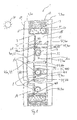
- FIG. 1 the cross-sectional structure of a solar collector 1 according to the invention is shown according to a preferred embodiment.
- the solar collector 1 comprises a front cover 200 and a rear rear wall 300, which are spaced from one another. Between the cover 200 and the rear wall 300, an absorber 78 is arranged, which comprises an absorber plate 7 which is fixedly connected to an absorber tube 8. Between the absorber plate 7 and the cover 2, a front cavity 14 is arranged. A rear cavity 15 is provided between the absorber plate 7 and the rear wall 300.
- the cavities 14, 15 are each sealed gas-tight relative to the environment. For this purpose, provision is made in particular for at least one spacer element 400 to be arranged between the absorber 78 and the cover 200 or the rear wall 300.
- a hollow profile 20 is arranged between the cover 200 and the rear wall 300, which is connected by a primary adhesive 11 with the cover 200 and the rear wall 300.
- a secondary adhesive 12 is further provided that the cover 200 and the rear wall 300 connects directly.
- the primary adhesive 11 preferably has a butyl based component.
- the secondary adhesive 12 preferably contains silicone.
- a drying means 13 is arranged in the hollow section 20, .
- the drying agent 13 may be embodied as a molecular sieve or comprise zeolite.
- the absorber plate 7 preferably extends over the entire surface of the solar collector 1 within the cavities 14, 15 defined by the hollow profile 20.
- the absorber plate 7 is coupled to the absorber tube 8 through the thermal connection 16 at least on one side. It is also possible that an absorber tube 8 is arranged on both sides of the absorber plate 7. Preferably, the absorber tube 8 is arranged on the side facing away from the solar radiation side of the absorber plate 7.
- a solar-selective coating 36 is further provided on the side of the absorber sheet facing the sun 37. The solar-selective coating 36 increases the efficiency of the absorber sheet 7.
- the cover 200 and the rear wall 300 may each be designed as front and rear glass pane 2, 3.
- the rear glass pane 3 or the rear wall 300 may include a reflective layer 19.
- the reflection layer 19 is arranged on the inside of the rear glass pane 3 or the rear wall 300.
- the reflection layer 19 is therefore arranged facing the absorber plate 7 or, in general, the absorber 100.
- the reflective layer 19 may comprise a low-E coating.
- the reflection layer 19 is coated in such a reflective manner that in particular or predominantly infrared radiation is reflected.
- the front glass pane 2 is preferably designed as a solar glass pane, in contrast to the rear glass pane 3. However, this does not exclude that the front glass pane 2 is also formed as required as insulating glass pane or thermal insulating glass.
- the front glass pane 2 designed as solar glass comprises an antireflection coating 17, 18 on both sides, a first antireflection coating 17 on the outside of the laminated glass pane 1, ie on the side of the front glass pane 2 facing the sun 37 and the second antireflection coating 18 on the rear side of the front pane Glass pane 2, that is, the absorber sheet 7 facing side of the front glass pane 2, is arranged.
- the antireflection coatings 17, 18 are preferably connected in a material-bonded manner to the front glass pane 2.
- the solar collector 1 In order to achieve the most constant possible efficiency of the solar collector 1, it is advantageously provided to fill the front cavity 14 and the rear cavity 15 with a protective gas, in particular argon. In this way the formation of condensation is avoided. In addition, the drying agents 13 cause a reduction of the condensation risk.
- a protective gas in particular argon.
- the absorber plate 7 and the absorber tube 8 preferably have a material with a high heat transfer coefficient, in particular copper.
- the thermal connection 16 preferably comprises a metal, in particular a weld seam or a solder joint, wherein the weld seam or the solder joint can be applied by a laser method or ultrasound method. This mechanical connection between copper tube or absorber tube 8 and copper sheet or absorber sheet 7 is thermally effective. This means that the thermal connection 16 contributes to the transfer of heat energy from the absorber plate 7 to the absorber tube 8.
- the front glass 2 and the rear glass 3 each preferably comprise a single-pane safety glass or a partially tempered glass or a laminated safety glass.
- spacer element 400 In the figure, different embodiments of the spacer element 400 are further shown in arrangement with the solar collector 1. It is to be understood that the spacer elements 400 shown are used not only in combination with each other but also separately in the solar collector according to the invention, and thus any combination of one of the illustrated spacer elements 400 with the solar collector 1 is disclosed and claimed.
- spacer element 400 is provided for reasons of clarity, each with different reference numerals.
- the first spacer element 400, 38 is pin-shaped and passes through the front cavity 14, the absorber plate 7 and the rear pane space 15.
- the first spacer element 400, 38 thus extends from the front cover 200 to the rear rear wall 300.
- the first spacer element 400, 38 includes a mounting portion 450 that extends through the absorber sheet 7.
- the attachment region 450 has a peripheral surface or peripheral partial surface 454 of the first spacer element 400, 38, which is connected to the absorber plate 7. This means that at least a part of the peripheral surface in the attachment section 450 is used for connecting the spacer element 400, 38 to the absorber 100 or absorber plate 7.
- the circumferential surface or peripheral partial surface 454 may be adhesively bonded, in particular adhesively bonded, to the absorber plate 7, in particular to an inner peripheral surface of an absorber plate bore, which passes through the first spacer element 400, 38.
- Another connection such as screw, connector or press connection, is possible. It is also conceivable to additionally fix the first spacer element 400, 38 mechanically or by gluing, soldering or welding.
- the second spacer element 400, 48 is substantially pin-shaped and further comprises positioning aids 48a, 48b.
- a front positioning aid 48a is cone-shaped, wherein the cone base is arranged in the region of the absorber plate 7.
- the rear positioning aid 48b thus forms a clamping means 455 or a snap closure.
- the second spacer element 400, 48 are guided through a bore in the absorber plate 7, wherein the second spacer element 400, 48 automatically fixed as soon as the rear positioning aid 48b is passed through the absorber plate 7.
- a third spacer element 400, 42 is formed like a pin, wherein the third spacer element 400, 42 extends from the rear wall 300 and the rear glass pane 3 to the absorber plate 7.
- the third spacer element 400, 42 is connected to the rear glass pane 3 by a splice 44 or glued to the rear glass pane 3.
- the splice 44 is arranged on an end face 460 of the third spacer element 400, 42.
- the third spacer element 400, 42 forms a rear spacer element 400.
- the rear spacer element 400 and the third spacer element 400, 42 is associated with a fourth, front spacer element 400, 43 which is bonded to the front glass plate 2 corresponding to the third spacer element 400, 42 and extends like a pin to the absorber plate 7.
- a splice 44 is provided between the front glass pane 2 and the front, fourth spacer element 400, 43, which is arranged in the region of the end face 460 of the fourth spacer element 400, 43.
- the absorber sheet 7 is held between the third and fourth spacer members 400, 42, 43. That is, the third and fourth spacer members 400, 42, 43 constitute a spacer set and an advantageous arrangement of two spacer members 400, namely, the third spacer member 400, 42 and the fourth spacer member 400, 43.
- a spacer element 400 which can be plug-connected or clip-connected to the absorber tube 8.
- Such a spacer element 400 shows the fifth spacer element 400, 45.
- the fifth spacer element 400, 45 has a front, C-shaped profile 457, which surrounds the absorber tube 8 or is clipped onto the absorber tube 8 for the purpose of a plug connection.
- the C-shaped profile 457 thus forms a releasable plug or clip connection.
- the fifth spacer element 400, 45 is arranged on the side facing away from the sun 37 of the absorber plate 7 and further comprises two in the direction of the rear Glass pane 3 or the rear wall 300 extending contact portions, preferably touching the rear glass pane 3 and the absorber 100 and the absorber plate 7 and the absorber tube 8 are supported against the rear wall 300. A different number of extending in the direction of the rear glass pane 3 tips is possible.
- a sixth spacer element 400, 39 has a substantially pin-like shape, wherein the sixth spacer element 400, 39 in the front cavity 14 forms a shape corresponding to the front positioning aid 48a of the second spacer element 400, 48.
- the clamping means 465 or the securing disk 41 can be screwed to the pin-like sixth spacer element 400, 39.
- the lock washer 41 forms with the front, conical portion of the sixth spacer element 400, 39 a clamping fixation for the absorber sheet. 7
- a seventh spacer element 400, 40 is formed like a profile and arranged in the region of the hollow profile 20.
- the spacer element 400, 40 is connected to the hollow profile 20 and has on the absorber sheet 7 side facing a groove 458, in which the absorber plate 7 engages.
- the groove depth of the groove 458 must be dimensioned such that the thermal expansion of the components, in particular of the absorber sheet 7, is taken into account, that is to say must be greater than the thermal expansion of the absorber sheet 7.
- the seventh spacer element 400, 40 is also supported on the cover 200 and the rear wall 300 and passes through the cavities 14, 15.
- the seventh spacer element 400, 40 is strip-like and has a longitudinal extent along an outer edge of the absorber plate. 7 continues.
- the seventh spacer element 400, 40 may be coupled to the absorber plate 7.
- the seventh spacer element 400, 40 may be connected to the absorber sheet 7 by squeezing, clamping, gluing or mechanical locking.
- the seventh spacer element 400, 40 comprises an injection molding element or an extrusion element made of a material mentioned in connection with the second spacer element 400, 48.
- each of said spacer elements 400 taken separately can be arranged in the solar collector 1 individually or in a plurality of arrangements. It is likewise possible for the abovementioned spacer elements 400 to be used in multiple combinations with one another in the solar collector 1.
- a plurality of first spacer elements 400, 38 may be provided in a laminated glass solar collector.
- a plurality of second spacer elements 400, 48, third spacer elements 400, 42, fourth spacer elements 400, 43, fifth spacer elements 400, 45, sixth spacer elements 400, 39 or seventh spacer elements 400, 40 may be provided. It is preferred to provide a plurality of identical spacer elements 400.
- the absorber 100 which is preferably arranged between a front glass pane 2 and a rear glass pane 3, comprises an absorber plate 7 and an absorber tube 8, which is arranged meander-shaped on the absorber plate 7.
- the absorber tube 8 is fixedly connected to the absorber plate 7, in particular such that between the absorber plate 7 and the absorber tube 8, a thermal connection, ie a heat transfer, is possible.
- the absorber plate 7 is further surrounded by the hollow profile 20 which is arranged between the rear glass pane 3 and the front glass pane 2.
- the absorber 100 and the absorber plate 7 in this case has a distance from the hollow profile 20.
- the absorber tube 8 comprises a supply line 9 and a discharge line 10, which are each led out of the solar collector 1.
- the supply line 9 and the discharge line 10 by the, in Fig. 2 not shown, rear glass pane 3 out.
- the supply line 9 and the discharge line 10 each form an angle piece.
- the supply line 9 is arranged in an upper region of the solar collector 1, whereas the discharge line 10 is arranged in a lower region of the solar collector. This is especially true if the solar collector is designed as a laminated glass solar collector, which is integrated in a substantially vertical arrangement in a building facade. It is also possible that the supply line 9 and the discharge line 10 are arranged in reverse.
- the absorber tube 8 has a plurality of meander-shaped windings, wherein the spacing of the meander-shaped windings preferably varies over the height or length of the absorber 100. It is preferred if an upper distance AO of the meandering turns is provided in the upper region of the absorber 100 or generally of the solar collector 1, which is smaller than a lower distance AU of the meandering turns in the lower region of the solar collector 1. Preferably, the distance increases the meandering turns from the upper distance AO continuously to the lower distance AU.
- the absorber tube density is thus preferably greater in the upper region of the solar collector 1 than in the lower region of the solar collector 1. This increases the efficiency of the energy conversion in the solar collector 1, in particular when integrating the insulating glass element or laminated glass solar collector in a building facade.
- This aspect of the different spacing of the meander-shaped bonds is claimed as an independent invention, thus independent of the provision of spacer elements.
- the spacer elements 400 between the absorber 100 and the rear wall 300 or the rear glass pane 3 and the cover 200 or the front glass pane 2 are preferably distributed over the absorber 100 in a planar manner.
Abstract
Description
Die Erfindung betrifft einen Solarkollektor sowie ein Verfahren zum Herstellen eines derartigen Solarkollektors.The invention relates to a solar collector and a method for producing such a solar collector.
Aus dem Stand der Technik sind Solarkollektoren bekannt, die eine Rückwand, einen umlaufenden Kollektorrahmen, ein Absorberelement und eine Abdeckung umfassen, wobei das Absorberelement zwischen der Rückwand und der Abdeckung angeordnet ist. Ein derartiger Solarkollektor ist beispielsweise in der
Bei dem bekannten Solarkollektor ist das Absorberelement direkt mit dem Kollektorrahmen verbunden. Durch die Absorption von Wärmestrahlung kann sich das Absorberelement ausdehnen, wodurch bei dem bekannten Solarkollektor die Gefahr besteht, dass sich der Rahmen verformt. Ferner besteht das Risiko, dass sich der Abstand zwischen der Abdeckung und dem Absorberelement durch die Erwärmung zumindest bereichsweise vergrößert, wodurch eine ungünstige Thermokonvektion und somit ein verringerter Wirkungsgrad begünstigt wird.In the known solar collector, the absorber element is connected directly to the collector frame. Due to the absorption of thermal radiation, the absorber element can expand, which in the known solar collector there is a risk that the frame deforms. Furthermore, there is the risk that the distance between the cover and the absorber element increases at least in regions as a result of the heating, as a result of which unfavorable thermoconvection and thus reduced efficiency are favored.
Der Erfindung liegt die Aufgabe zugrunde, einen Solarkollektor anzugeben, der einen gleichbleibenden Wirkungsgrad aufweist und insbesondere konstruktiv derart ausgeführt ist, dass eine ausreichende Bewegungsfreiheit für den Absorber bereitgestellt ist. Ferner liegt der Erfindung die Aufgabe zugrunde, ein Verfahren zur Herstellung eines derartigen Solarkollektors anzugeben.The invention has for its object to provide a solar collector, which has a constant efficiency and designed in particular constructive way is that a sufficient freedom of movement for the absorber is provided. Furthermore, the invention has for its object to provide a method for producing such a solar collector.
Erfindungsgemäß wird diese Aufgabe im Hinblick auf den Solarkollektor durch den Gegenstand des Patentanspruchs 1 und im Hinblick auf das Herstellungsverfahren durch den Gegenstand des Patentanspruchs 14 gelöst.According to the invention this object is achieved with regard to the solar collector by the subject-matter of
Die Erfindung beruht auf dem Gedanken, einen Solarkollektor mit einer Abdeckung, einer Rückwand und einem Absorber anzugeben, der zwischen der Abdeckung und der Rückwand angeordnet ist und mit der Abdeckung und der Rückwand jeweils einen vorderen und hinteren Hohlraum begrenzt. Dabei ist wenigstens ein Abstandshalteelement vorgesehen, das sich von einer vorderen Oberfläche des Absorbers zur Abdeckung und/oder von einer hinteren Oberfläche des Absorbers zur Rückwand erstreckt. Das Abstandshalteelement ist ferner mit dem Absorber und/oder der Abdeckung direkt verbunden oder verbindbar. Schließlich sind der vordere Hohlraum und der hintere Hohlraum mit einem Schutzgas, insbesondere Argon, befüllt.The invention is based on the idea to provide a solar collector with a cover, a rear wall and an absorber, which is arranged between the cover and the rear wall and bounded by the cover and the rear wall in each case a front and rear cavity. In this case, at least one spacer element is provided, which extends from a front surface of the absorber to the cover and / or from a rear surface of the absorber to the rear wall. The spacer element is further connected or connectable directly to the absorber and / or the cover. Finally, the front cavity and the rear cavity are filled with a protective gas, in particular argon.
Durch das Abstandshalteelement wird ein gleichbleibender Abstand zwischen dem Absorber bzw. vorderen oder hinteren Oberfläche des Absorbers und der Abdeckung bzw. der Rückwand bereitgestellt. Eine ungünstige Thermokonvektion durch einen vergrößerten Abstand zwischen dem Absorber und insbesondere der Abdeckung wird somit vermieden. Dabei erstreckt sich das Abstandshalteelement von der vorderen Oberfläche des Absorbers zur Abdeckung. Alternativ oder zusätzlich erstreckt sich das Abstandshalteelement von der hinteren Oberfläche des Absorbers zur Rückwand. Das Abstandshalteelement kann sich also auch von der Rückwand zur Abdeckung erstrecken, wobei das Abstandshalteelement dabei vorzugsweise den Absorber durchgreift. Im Allgemeinen ist das Abstandshalteelement rechtwinklig zur vorderen oder hinteren Oberfläche des Absorbers angeordnet.By the spacer element, a constant distance between the absorber and the front or rear surface of the absorber and the cover or the rear wall is provided. An unfavorable thermoconvection by an increased distance between the absorber and in particular the cover is thus avoided. In this case, the spacer element extends from the front surface of the absorber to the cover. Alternatively or additionally, the spacer element extends from the rear surface of the absorber to the rear wall. The spacer element may thus also extend from the rear wall to the cover, wherein the spacer element preferably engages through the absorber. In general, the spacer element is arranged perpendicular to the front or rear surface of the absorber.
Es wird darauf hingewiesen, dass die vordere Oberfläche des Absorbers im Gebrauch vorzugsweise der Sonneneinstrahlung zugewandt und die hintere Oberfläche des Absorbers der Sonneneinstrahlung abgewandt angeordnet ist. Die Abdeckung ist dabei auf der der Sonneneinstrahlung zugewandten Seite des Absorbers und die Rückwand auf der der Sonneneinstrahlung abgewandten Seite des Absorbers positioniert.It should be noted that the front surface of the absorber in use preferably facing the sun and the rear surface of the absorber is arranged facing away from the sun's rays. The cover is positioned on the side of the absorber facing the solar irradiation and the rear wall is positioned on the side of the absorber facing away from the solar radiation.
Die Abdeckung und/oder die Rückwand können ein Glas, insbesondere ein Wärmedämmglas, umfassen. Dadurch wird eine Art Isolierglasverbund bzw. Isolierglaselement bereitgestellt, das einen zentralen Absorber umfasst. Dabei kommen die im Zusammenhang mit dem Abstandshalteelement genannten Vorteile besonders effektiv zum Tragen. Insbesondere wird durch die Abstandshalteelemente erreicht, dass der Solarkollektor durch Standardprofile herstellbar ist, wodurch die Produktionskosten verringert werden. Ferner kann der Absorber, frei innerhalb des Standardprofils angeordnet sein und besitzt somit ausreichend Bewegungsfreiheit bei einer thermisch bedingten Dimensionsänderung. Insgesamt ermöglichen die Abstandshalteelemente eine einfache und kostengünstige Montage des Solarkollektors, insbesondere des Isolierglaselements mit integriertem Thermosolarkollektor. Die Abstandshalteelemente ermöglichen auch eine Montage und/oder den Gebrauch bzw. die Nutzung des Solarkollektors in Schräglage oder waagrecht auf einem Tisch.The cover and / or the rear wall may comprise a glass, in particular a thermal insulating glass. As a result, a type of insulating glass composite or insulating glass element is provided which comprises a central absorber. The advantages mentioned in connection with the spacer element are particularly effective. In particular, it is achieved by the spacer elements that the solar collector can be produced by standard profiles, whereby the production costs are reduced. Furthermore, the absorber can be arranged freely within the standard profile and thus has sufficient freedom of movement in the case of a thermally induced dimensional change. Overall, the spacer elements allow a simple and cost-effective installation of the solar collector, in particular of the insulating glass element with integrated Thermosolarkollektor. The spacer elements also allow for mounting and / or the use or the use of the solar collector in an inclined position or horizontally on a table.
Vorzugsweise ist das Abstandshalteelement stiftartig ausgebildet. Das Abstandshalteelement weist somit einen relativ geringen Querschnitt auf, so dass die Funktion des Absorbers kaum beeinträchtigt wird.Preferably, the spacer element is formed like a pin. The spacer element thus has a relatively small cross section, so that the function of the absorber is hardly affected.
Im Allgemeinen weist das Abstandshalteelement vorzugsweise einen weichmacherfreien Kunststoff auf. Der Kunststoff ist zweckmäßigerweise für in dem Solarkollektor auftretende Temperaturen temperaturbeständig. Dazu kann der Kunststoff Glasfaserbeimengungen aufweisen, die die Steifigkeit des Kollektors ganz allgemein, insbesondere auch für den Fall des Stillstandes (Stagnation), erhöhen. Anstelle eines derartigen, thermoplastischen Kunststoffs können auch duroplastische Kunststoffe oder Keramikmaterialien eingesetzt werden.In general, the spacer element preferably comprises a plasticizer-free plastic. The plastic is expediently temperature-resistant for temperatures occurring in the solar collector. For this purpose, the plastic glass fiber admixtures which increase the rigidity of the collector in general, especially for the case of stagnation. Instead of such a thermoplastic plastic and thermosetting plastics or ceramic materials can be used.
Das Abstandshalteelement kann einen Befestigungsbereich aufweisen, der mit dem Absorber direkt verbunden oder verbindbar ist. Es ist also möglich, dass der Absorber mit dem Abstandshalteelement eine Einheit bildet, wobei nicht ausgeschlossen ist, dass der Absorber mit mehreren Abstandshalteelementen verbunden ist.The spacer element may have a mounting area that is directly connected or connectable to the absorber. It is therefore possible that the absorber forms a unit with the spacer element, wherein it is not excluded that the absorber is connected to a plurality of spacer elements.
Der Befestigungsbereich kann ferner eine Stirnfläche, insbesondere axiale Stirnfläche, des Abstandshalteelements umfassen. Zur Verbindung des Absorbers mit dem Abstandshalteelement sind somit keine besonderen konstruktiven Gestaltungselemente oder Maßnahmen am Absorber erforderlich.The attachment region may further comprise an end face, in particular axial end face, of the spacer element. For connecting the absorber with the spacer element thus no special structural design elements or measures on the absorber are required.
Der Befestigungsbereich kann alternativ eine Umfangsteilfläche des Abstandshalteelements umfassen. Es ist auch möglich, dass der Befestigungsbereich eine vollständige Umfangsfläche des Abstandshalteelements umfasst. Durch die Umfangsfläche kann das Abstandshalteelement beispielsweise mit einer Bohrung im Absorber gekoppelt bzw. verbunden werden. Die Umfangsteilfläche bzw. Umfangsfläche kann auch ein Gewinde umfassen, das mit einem Gegengewinde in dem Absorber zusammenwirkt.The attachment region may alternatively comprise a peripheral part surface of the spacer element. It is also possible that the attachment area comprises a complete peripheral surface of the spacer element. By the peripheral surface, the spacer element can be coupled or connected, for example, with a bore in the absorber. The peripheral surface may also include a thread that cooperates with a counter thread in the absorber.
Vorzugsweise umfasst das Abstandshalteelement wenigstens ein Klemmmittel oder Spannmittel, das den Befestigungsbereich begrenzt. Das Klemmmittel oder Spannmittel ermöglicht eine einfache und schnelle Verbindung des Abstandshalteelements mit dem Absorber. Beispielsweise kann das Klemmmittel schnappverschlussartig ausgebildet sein. Das Klemmmittel kann sich beispielsweise zur Befestigung mit dem Absorber aufspannen und eine widerhakenähnliche Arretierung bilden. Das Spannmittel kann beispielsweise eine Gewindemutter umfassen, die mit einem Fixierungselement derart zusammenwirkt, dass der Absorber zwischen dem Fixierungselement und der Mutter einspannbar ist.Preferably, the spacer element comprises at least one clamping means or clamping means which limits the mounting area. The clamping means or clamping means allows a simple and quick connection of the spacer element with the absorber. For example, the clamping means may be formed like a snap closure. The clamping means can, for example, span for attachment to the absorber and form a barb-like locking. The clamping means may for example comprise a threaded nut, which cooperates with a fixing element such that the absorber between the fixing element and the nut can be clamped.
Bei einer bevorzugten Ausführungsform des erfindungsgemäßen Solarkollektors umfasst der Absorber ein Absorberblech oder ein Absorberrohr, das mit dem Abstandshalteelement direkt verbunden oder verbindbar ist.In a preferred embodiment of the solar collector according to the invention, the absorber comprises an absorber plate or an absorber tube which is directly connected or connectable to the spacer element.
Der Befestigungsbereich kann ein schienenartiges, insbesondere C-förmiges Profil bilden, das mit dem Absorberrohr verbunden oder verbindbar, insbesondere klemmverbindbar ist. Die Montage des Solarkollektors wird damit weiter vereinfacht. Insbesondere ist es mit dem C-förmigen Profil des Befestigungsbereichs möglich, das Abstandshalteelement einfach auf das Absorberrohr zu clipsen bzw. zu stecken. Zusätzliche Verbindungen bzw. Verbindungsmaßnahmen sind nicht zwingend erforderlich.The attachment region can form a rail-like, in particular C-shaped profile which is connected to the absorber tube or can be connected, in particular clamp-connected. The assembly of the solar collector is thus further simplified. In particular, with the C-shaped profile of the attachment area, it is possible to simply clip or place the spacer element onto the absorber tube. Additional connections or connection measures are not mandatory.
Der Befestigungsbereich kann ferner eine Nut umfassen, die eine Seitenfläche des Absorberblechs umgreift. Vorzugsweise ist ein derartiges Abstandshalteelement plattenartig ausgebildet und weist zum Absorber hin den als Nut ausgebildeten Befestigungsbereich auf. Dabei kann das Abstandshalteelement ein Profilelement bilden, das das Absorberblech rahmenartig bzw. leistenartig umgibt.The attachment region may further include a groove that engages around a side surface of the absorber sheet. Preferably, such a spacer element is plate-like and has the absorber toward the mounting portion formed as a groove. In this case, the spacer element may form a profile element, which surrounds the absorber sheet like a frame or strip-like.
Das Abstandshalteelement ist vorzugsweise mit dem Absorber verklebt und/oder verschweißt und/oder schraubverbunden und/oder pressverbunden. Andere Verbindungsarten sind ebenfalls möglich. Im Allgemeinen ist es vorteilhaft, wenn das Abstandshalteelement mit dem Absorber derart verbunden ist, dass der Absorber mit dem oder den mehreren Abstandshalteelementen eine Einheit bildet. Eine derartige Absorbereinheit kann beispielsweise vorgefertigt bereitgestellt werden, so dass die Endmontage des Solarkollektors vereinfacht und beschleunigt wird.The spacer element is preferably glued to the absorber and / or welded and / or screw-connected and / or press-connected. Other connection types are also possible. In general, it is advantageous if the spacer element is connected to the absorber in such a way that the absorber forms a unit with the one or more spacer elements. Such an absorber unit can for example be provided prefabricated, so that the final assembly of the solar collector is simplified and accelerated.
Gemäß einem nebengeordneten Aspekt beruht die Erfindung auf dem Gedanken, ein Verfahren zum Herstellen eines derartigen Solarkollektors anzugeben, wobei wenigstens ein Abstandshalteelement mit einem Absorber verbunden und der Absorber anschließend zwischen einer Rückwand und einer Abdeckung angeordnet wird. Dabei weist der Absorber zur Rückwand und/oder zur Abdeckung einen Abstand auf, der durch die Länge des Abstandshalteelements bestimmt ist.According to a secondary aspect, the invention is based on the idea to provide a method for producing such a solar collector, wherein at least one spacer element connected to an absorber and the absorber is then arranged between a rear wall and a cover. In this case, the absorber to the rear wall and / or the cover at a distance which is determined by the length of the spacer element.
Die Abstandshalteelemente zwischen dem Absorber und der Rückwand bzw. der hinteren Glasscheibe und der Abdeckung bzw. der vorderen Glasscheibe sind vorzugsweise flächig über dem Absorber verteilt. Es sind also vorzugsweise mehrere Abstandshalteelemente vorgesehen, die sich vom Absorber zur Abdeckung und/oder zur Rückwand erstrecken. Die Verteilung der Abstandshalteelemente ist dabei vorzugsweise derart angepasst, dass temperaturbedingte Verformungen des Absorbers im Wesentlichen gedämpft werden. Beispielsweise können die Abstandshalteelemente derart verteilt sein, dass jeweils einem Abstandshalteelement höchstens 2500 cm2, insbesondere höchstens 2025 cm2, insbesondere höchstens 1600 cm2, insbesondere höchstens 1225 cm2, insbesondere höchstens 900 cm2, insbesondere höchstens 625 cm2, insbesondere höchstens 400 cm2, insbesondere höchstens 225 cm2, insbesondere höchstens 100 cm2, insbesondere höchstens 25 cm2, der Oberfläche des Absorbers bzw. Absorberblechs zugeordnet sind.The spacer elements between the absorber and the rear wall or the rear glass pane and the cover or the front glass pane are preferably distributed over the absorber surface. Thus, there are preferably provided a plurality of spacer elements which extend from the absorber to the cover and / or to the rear wall. The distribution of the spacer elements is preferably adapted such that temperature-induced deformations of the absorber are substantially attenuated. For example, the spacer elements can be distributed such that in each case a spacer element at most 2500 cm 2 , in particular at most 2025 cm 2 , in particular at most 1600 cm 2 , in particular at most 1225 cm 2 , in particular at most 900 cm 2 , in particular at most 625 cm 2 , in particular at most 400 cm 2 , in particular at most 225 cm 2 , in particular at most 100 cm 2 , in particular at most 25 cm 2 , are assigned to the surface of the absorber or absorber sheet.
Vorteilhafterweise sind die Abstandshalteelemente in einem zentralen Bereich des Absorbers bzw. Absorberblechs angeordnet. Beispielsweise können die Abstandshalteelemente nur in dem Bereich des Absorberblechs angeordnet sein, in dem auch das Absorberrohr positioniert ist. Der Randbereich des Absorbers kann frei von Abstandshalteelementen sein. Ein derartiger, freier Randbereich des Absorbers umfasst vorzugsweise wenigstens 5%, insbesondere wenigstens 10%, insbesondere wenigstens 15%, insbesondere wenigstens 20%, der Gesamtfläche des Absorbers bzw. des Absorberblechs. Vorzugsweise erstreckt sich der abstandhalteelementfreie Randbereich des Absorbers bzw. Absorberblechs wenigstens 2 cm, insbesondere wenigstens 5 cm, insbesondere wenigstens 10 cm, insbesondere wenigstens 15 cm, von den Außenkanten des Absorbers bzw. Absorberblechs in Richtung des Zentrums des Absorbers.Advantageously, the spacer elements are arranged in a central region of the absorber or absorber plate. For example, the spacer elements may be arranged only in the region of the absorber plate, in which the absorber tube is positioned. The edge region of the absorber can be free of spacer elements. Such a free edge region of the absorber preferably comprises at least 5%, in particular at least 10%, in particular at least 15%, in particular at least 20%, of the total area of the absorber or of the absorber sheet. Preferably, the spacer element-free edge region of the absorber or absorber sheet extends at least 2 cm, in particular at least 5 cm, in particular at least 10 cm, in particular at least 15 cm, from the outer edges of the absorber or absorber plate in the direction of the center of the absorber.
Die Abstandshalteelemente können über die Oberfläche des Absorbers gleichmäßig verteilt sein. Es ist allerdings nicht ausgeschlossen, dass die Abstandshalteelemente über die Oberfläche des Absorbers ungleichmäßig verteilt sind. Die Verteilung der Abstandshalteelemente kann derart gewählt sein, dass zu erwartende, thermische Verformungen des Absorbers gezielt gestützt werden. Beispielsweise können mittels einer FEM-Analyse Verformungsbereiche des Absorbers vorab bestimmt werden, so dass gezielt in diesen Bereichen Abstandshalteelemente angeordnet werden. Die Anzahl der Abstandshalteelemente kann auf diese Weise derart gewählt werden, dass ein Gleichgewicht zwischen minimaler Anzahl an Abstandshalteelementen und größtmöglicher Stützung des Absorbers eingestellt ist.The spacer elements may be evenly distributed over the surface of the absorber. However, it is not excluded that the spacer elements are distributed unevenly over the surface of the absorber. The distribution of the spacer elements can be selected such that expected, thermal deformations of the absorber are selectively supported. For example, deformation regions of the absorber can be determined in advance by means of an FEM analysis, so that spacer elements are specifically arranged in these regions. The number of spacer elements can be chosen in this way so that a balance between a minimum number of spacer elements and the greatest possible support of the absorber is set.
Die Abstandshalteelemente sind vorzugsweise mit dem Absorber bzw. dem Absorberblech verbunden. Es ist möglich, dass der Absorber ein vorgefertigtes Bauteil für den Solarkollektor bildet, wobei die Abstandshalteelemente Bestandteil des vorgefertigten Bauteils bzw. Absorbers sind. Dazu können die Abstandshalteelemente integral oder einteilig mit dem Absorber ausgebildet sein. Vorzugsweise bilden der Absorber und die Abstandshalteelemente eine gemeinsame Baugruppe.The spacer elements are preferably connected to the absorber or the absorber sheet. It is possible that the absorber forms a prefabricated component for the solar collector, wherein the spacer elements are part of the prefabricated component or absorber. For this purpose, the spacer elements may be formed integrally or integrally with the absorber. Preferably, the absorber and the spacer elements form a common assembly.
Alternativ können die Abstandshalteelemente als Bestandteile der Abdeckung oder der Rückwand vorgefertigt sein. Die Abdeckung bzw. die vordere Glasscheibe und/oder die Rückwand bzw. die hintere Glasscheibe können also bereits vorgefertigte Abstandshalteelemente umfassen bzw. mit den Abstandshalteelementen einteilig ausgebildet sein. Die Abstandshalteelemente können dabei einen integralen Bestandteil der Abdeckung bzw. der Rückwand bilden.Alternatively, the spacer elements may be prefabricated as components of the cover or the rear wall. The cover or the front glass pane and / or the rear wall or the rear glass pane can thus already comprise prefabricated spacer elements or be integrally formed with the spacer elements. The spacer elements can form an integral part of the cover or the rear wall.
Die im Zusammenhang mit dem Solarkollektor genannten Vorteile und Wirkungen gelten im Wesentlichen analog für das erfindungsgemäße Herstellungsverfahren.The advantages and effects mentioned in connection with the solar collector apply substantially analogously to the production method according to the invention.
Bevorzugte Ausführungsformen der Erfindung werden im Folgenden unter Bezugnahme auf die beigefügten, schematischen Zeichnungen näher erläutert. Darin zeigen
- Fig. 1
- einen Querschnitt durch eine Ausführungsform eines erfindungsgemäßen Solarkollektor mit unterschiedlichen Abstandshalteelementen gemäß bevorzugten Ausführungsbeispielen; und
- Fig. 2
- einen Längsschnitt durch einen Solarkollektor nach einem weiteren bevorzugten Ausführungsbeispiel.
- Fig. 1
- a cross-section through an embodiment of a solar collector according to the invention with different spacer elements according to preferred embodiments; and
- Fig. 2
- a longitudinal section through a solar collector according to a further preferred embodiment.
In
Im Randbereich des Solarkollektors 1 ist zwischen der Abdeckung 200 und der Rückwand 300 ein Hohlprofil 20 angeordnet, das durch ein primäres Haftmittel 11 mit der Abdeckung 200 und der Rückwand 300 verbunden ist. Außerhalb des Hohlprofils 20 ist ferner ein sekundäres Haftmittel 12 vorgesehen, dass die Abdeckung 200 und die Rückwand 300 direkt verbindet. Das primäre Haftmittel 11 weist vorzugsweise eine auf Butyl basierende Komponente auf. Das sekundäre Haftmittel 12 enthält vorzugsweise Silikon. Im Hohlprofil 20 ist ein Trocknungsmittel 13 angeordnet. Das Trocknungsmittel 13 kann als Molekularsieb ausgeführt sein bzw. Zeolith umfassen.In the edge region of the
Das Absorberblech 7 erstreckt sich vorzugsweise über die gesamte Fläche des Solarkollektors 1 innerhalb der durch das Hohlprofil 20 begrenzten Hohlräume 14, 15. Das Absorberblech 7 ist zumindest auf einer Seite mit dem Absorberrohr 8 durch die thermische Verbindung 16 gekoppelt. Es ist auch möglich, dass beidseitig des Absorberblechs 7 ein Absorberrohr 8 angeordnet ist. Vorzugsweise ist das Absorberrohr 8 auf der der Sonneneinstrahlung abgewandten Seite des Absorberblechs 7 angeordnet. Auf der der Sonne 37 zugewandten Seite des Absorberblechs ist ferner eine solarselektive Beschichtung 36 vorgesehen. Die solarselektive Beschichtung 36 erhöht den Wirkungsgrad des Absorberblechs 7.The
Die Abdeckung 200 und die Rückwand 300 können jeweils als vordere bzw. hintere Glasscheibe 2, 3 ausgeführt sein. Die hintere Glasscheibe 3 bzw. die Rückwand 300 kann eine Reflexionsschicht 19 umfassen. Die Reflexionsschicht 19 ist auf der Innenseite der hinteren Glasscheibe 3 bzw. der Rückwand 300 angeordnet. Die Reflexionsschicht 19 ist also dem Absorberblech 7 bzw. allgemein dem Absorber 100 zugewandt angeordnet. Die Reflexionsschicht 19 kann eine Low-E-Beschichtung umfassen. In einer besonders vorteilhaften Ausgestaltung ist die Reflexionsschicht 19 derart reflektierend beschichtet, dass insbesondere bzw. überwiegend Infrarotstrahlung reflektiert wird.The cover 200 and the rear wall 300 may each be designed as front and
Die vordere Glasscheibe 2 ist im Gegensatz zur hinteren Glasscheibe 3 vorzugsweise als Solarglasscheibe ausgeführt. Das schließt allerdings nicht aus, dass die vordere Glasscheibe 2 bedarfsweise auch als Isolierglasscheibe bzw. Wärmedämmglas ausgebildet ist.The
Die als Solarglas ausgebildete vordere Glasscheibe 2 umfasst beidseitig eine Antireflexbeschichtung 17, 18, wobei eine erste Antireflexbeschichtung 17 auf der Außenseite der Verbundglasscheibe 1, also auf der der Sonne 37 zugewandten Seite der vorderen Glasscheibe 2 und die zweite Antireflexbeschichtung 18 auf der hinteren Seite der vorderen Glasscheibe 2, also der dem Absorberblech 7 zugewandten Seite der vorderen Glasscheibe 2, angeordnet ist. Die Antireflexbeschichtungen 17, 18 sind vorzugsweise stoffschlüssig mit der vorderen Glasscheibe 2 verbunden.The
Um einen möglichst konstanten Wirkungsgrad des Solarkollektors 1 zu erreichen, ist vorteilhaft vorgesehen, den vorderen Hohlraum 14 und den hinteren Hohlraum 15 mit einem Schutzgas, insbesondere Argon, zu befüllen. Auf diese Weise wird die Bildung von Kondensation vermieden. Zusätzlich bewirken die Trocknungsmittel 13 eine Reduzierung des Kondensationsrisikos.In order to achieve the most constant possible efficiency of the
Das Absorberblech 7 und das Absorberrohr 8 weisen vorzugsweise ein Material mit einem hohen Wärmeübergangskoeffizienten, insbesondere Kupfer, auf. Die thermische Verbindung 16 umfasst vorzugsweise ein Metall, insbesondere eine Schweißnaht bzw. eine Lötstelle, wobei die Schweißnaht bzw. die Lötstelle durch ein Laserverfahren bzw. Ultraschallverfahren aufgebracht werden kann. Diese mechanische Verbindung zwischen Kupferrohr bzw. Absorberrohr 8 und Kupferblech bzw. Absorberblech 7 ist thermisch wirksam. Das bedeutet, dass die thermische Verbindung 16 zur Übertragung von Wärmeenergie vom Absorberblech 7 zum Absorberrohr 8 beiträgt.The
Die vordere Glasscheibe 2 und die hintere Glasscheibe 3 umfassen jeweils vorzugsweise ein Einscheibensicherheitsglas oder ein teilvorgespanntes Glas oder ein Verbundsicherheitsglas.The
In der Figur sind ferner unterschiedliche Ausführungsbeispiele des Abstandshalteelements 400 in Anordnung mit dem Solarkollektor 1 dargestellt. Es ist vorauszuschicken, dass die dargestellten Abstandshalteelemente 400 nicht nur in Kombination miteinander, sondern auch separat in dem erfindungsgemäßen Solarkollektor Anwendung finden und somit jede Kombination eines der dargestellten Abstandshalteelemente 400 mit dem Solarkollektor 1 offenbart und beansprucht wird.In the figure, different embodiments of the
Nachfolgend werden einzelne Ausführungsbeispiele des Abstandshalteelements 400 aus Gründen der Übersichtlichkeit mit jeweils unterschiedlichen Bezugzeichen versehen.Below, individual embodiments of the
Das erste Abstandshalteelement 400, 38 ist stiftartig ausgebildet und durchgreift den vorderen Hohlraum 14, das Absorberblech 7 und den hinteren Scheibenzwischenraum 15. Das erste Abstandshalteelement 400, 38 erstreckt sich somit von der vorderen Abdeckung 200 bis zur hinteren Rückwand 300. Das erste Abstandshalteelement 400, 38 umfasst einen Befestigungsbereich 450, der sich durch das Absorberblech 7 erstreckt. Der Befestigungsbereich 450 weist eine Umfangsfläche bzw. Umfangsteilfläche 454 des ersten Abstandshalteelements 400, 38 auf, die mit dem Absorberblech 7 verbunden ist. Das bedeutet, dass zumindest ein Teil der Umfangsfläche im Befestigungsabschnitt 450 zur Verbindung des Abstandshalteelements 400, 38 mit dem Absorber 100 bzw. Absorberblech 7 genutzt wird. Die Umfangsfläche bzw. Umfangsteilfläche 454 kann mit dem Absorberblech 7, insbesondere mit einer Innenumfangsfläche einer Absorberblechbohrung, die das erste Abstandshalteelement 400, 38 durchgreift, adhäsionsverbunden, insbesondere verklebt, sein. Eine andere Verbindung, beispielsweise Schraubverbindung, Steckverbindung oder Pressverbindung, ist möglich. Es ist auch denkbar, das erste Abstandshalteelement 400, 38 zusätzlich mechanisch oder durch Kleben, Löten oder Schweißen zu fixieren.The
Eine Weiterbildung des ersten Abstandshalteelements 400, 38 ist mit dem zweiten Abstandshalteelement 400, 48 verwirklicht. Das zweite Abstandshalteelement 400, 48 ist im Wesentlichen stiftartig ausgebildet und umfasst ferner Positionierhilfen 48a, 48b. Dabei ist eine vordere Positionierhilfe 48a konusförmig ausgebildet, wobei die Konusbasis im Bereich des Absorberblechs 7 angeordnet ist. Eine hintere Positionierhilfe 48b, die an der der Sonne 37 abgewandten Seite des Absorberblechs 7 angeordnet ist, ist flügelartig ausgebildet, wobei die Flügel der hinteren Positionierhilfe 48b flexibel sind. Die hintere Positionierhilfe 48b bildet somit ein Klemmmittel 455 bzw. einen Schnappverschluss. Auf diese Weise kann das zweite Abstandshalteelement 400, 48 durch eine Bohrung im Absorberblech 7 geführt werden, wobei sich das zweite Abstandshalteelement 400, 48 selbsttätig fixiert, sobald die hintere Positionierhilfe 48b durch das Absorberblech 7 hindurchgeführt ist.A development of the
Ein drittes Abstandhalteelement 400, 42 ist stiftartig ausgebildet, wobei sich das dritte Abstandshalteelement 400, 42 von der Rückwand 300 bzw. der hinteren Glasscheibe 3 bis zum Absorberblech 7 erstreckt. Das dritte Abstandshalteelement 400, 42 ist mit der hinteren Glasscheibe 3 durch eine Klebestelle 44 verbunden bzw. mit der hinteren Glasscheibe 3 verklebt. Die Klebestelle 44 ist an einer Stirnfläche 460 des dritten Abstandshalteelements 400, 42 angeordnet. Das dritte Abstandshalteelement 400, 42 bildet ein hinteres Abstandshalteelement 400. Dem hinteren Abstandshalteelement 400 bzw. dem dritten Abstandshalteelement 400, 42 ist ein viertes, vorderes Abstandshalteelement 400, 43 zugeordnet, das korrespondierend zum dritten Abstandshalteelement 400, 42 mit der vorderen Glasscheibe 2 verklebt ist und sich stiftartig zum Absorberblech 7 erstreckt. Dazu ist zwischen der vorderen Glasscheibe 2 und dem vorderen, vierten Abstandshalteelement 400, 43 eine Klebestelle 44 vorgesehen, die im Bereich der Stirnfläche 460 des vierten Abstandshalteelements 400, 43 angeordnet ist. Das Absorberblech 7 ist zwischen dem dritten und dem vierten Abstandshalteelement 400, 42, 43 gehalten. Das bedeutet, dass das dritte und vierte Abstandshalteelement 400, 42, 43 ein Abstandshalterset bzw. eine vorteilhafte Anordnung zweier Abstandshalteelemente 400, nämlich des dritten Abstandshalteelements 400, 42 und des vierten Abstandshalteelements 400, 43, bilden.A
Es ist ebenfalls möglich, ein Abstandshalteelement 400 vorzusehen, das mit dem Absorberrohr 8 steckverbindbar bzw. clipverbindbar ist. Ein derartiges Abstandshalteelement 400 zeigt das fünfte Abstandshalteelement 400, 45. Das fünfte Abstandshalteelement 400, 45 weist ein vorderes, C-förmiges Profil 457 auf, das zum Zwecke einer Steckverbindung das Absorberrohr 8 umgreift bzw. auf das Absorberrohr 8 geclipst ist. Das C-förmige Profil 457 bildet somit eine lösbare Steck- bzw. Clipverbindung.It is likewise possible to provide a
Das fünfte Abstandshalteelement 400, 45 ist auf der der Sonne 37 abgewandten Seite des Absorberblechs 7 angeordnet und umfasst ferner zwei sich in Richtung der hinteren Glasscheibe 3 bzw. der Rückwand 300 erstreckende Anlageabschnitte, die vorzugsweise die hintere Glasscheibe 3 berühren und den Absorber 100 bzw. das Absorberblech 7 und das Absorberrohr 8 gegen die Rückwand 300 abstützen. Eine andere Anzahl von sich in Richtung der hinteren Glasscheibe 3 erstreckenden Spitzen ist möglich.The
Ein sechstes Abstandshalteelement 400, 39 weist eine im Wesentlichen stiftartige Form auf, wobei das sechste Abstandshalteelement 400, 39 im vorderen Hohlraum 14 eine der vorderen Positionierhilfe 48a des zweiten Abstandshalteelements 400, 48 entsprechende Form bildet. Im Unterschied zu dem zweiten Abstandshalteelement 400, 48 weist das sechste Abstandshalteelement 400, 39 auf der Rückseite 103 des Absorberblechs 7 bzw. auf der der hinteren Glasscheibe 3 zugewandten Seite des Absorberblechs 7 ein Spannmittel 465, insbesondere eine Sicherungsscheibe 41, auf. Das Spannmittel 465 bzw. die Sicherungsscheibe 41 kann mit dem stiftartigen sechsten Abstandshalteelement 400, 39 verschraubt sein. Die Sicherungsscheibe 41 bildet mit dem vorderen, konusförmigen Abschnitt des sechsten Abstandshalteelements 400, 39 eine Klemmfixierung für das Absorberblech 7.A
Ein siebtes Abstandshalteelement 400, 40 ist profilartig ausgebildet und im Bereich des Hohlprofils 20 angeordnet. Insbesondere ist das Abstandshalteelement 400, 40 mit dem Hohlprofil 20 verbunden und weist auf der dem Absorberblech 7 zugewandten Seite eine Nut 458 auf, in die das Absorberblech 7 eingreift. Die Nuttiefe der Nut 458 muss dabei derart bemessen sein, dass der thermischen Ausdehnung der Bauteile, insbesondere des Absorberblechs 7, Rechnung getragen wird, muss also größer als die thermische Ausdehnung des Absorberblechs 7 bemessen sein. Das siebte Abstandshalteelement 400, 40 stützt sich ferner an der Abdeckung 200 und der Rückwand 300 ab und durchgreift die Hohlräume 14, 15. Vorzugsweise ist das siebte Abstandshalteelement 400, 40 leistenartig ausgebildet und weist eine Längserstreckung auf, die sich entlang einer Außenkante des Absorberblechs 7 fortsetzt. Das siebte Abstandshalteelement 400, 40 kann mit dem Absorberblech 7 gekoppelt sein. Dabei kann das siebte Abstandshalteelement 400, 40 mit dem Absorberblech 7 durch Quetschen, Klemmen, Kleben oder mechanischem Verriegeln verbunden sein. Vorzugsweise umfasst das siebte Abstandshalteelement 400, 40 ein Spritzgusselement oder ein Extrusionselement aus einem im Zusammenhang mit dem zweiten Abstandshalteelement 400, 48 genannten Material.A
Es wird darauf hingewiesen, dass jedes der genannten Abstandshalteelemente 400 für sich genommen einzeln oder in mehrfacher Anordnung in dem Solarkollektor 1 angeordnet sein kann. Es ist ebenfalls möglich, dass die genannten Abstandshalteelemente 400 in mehrfachen Kombinationen miteinander in dem Solarkollektor 1 zum Einsatz kommen. Beispielsweise können mehrere erste Abstandshalteelemente 400, 38 in einem Verbundglas-Solarkollektor vorgesehen sein. Alternativ oder zusätzlich können mehrere zweite Abstandshalteelemente 400, 48, dritte Abstandshalteelemente 400, 42, vierte Abstandshalteelemente 400, 43, fünfte Abstandshalteelemente 400, 45, sechste Abstandshalteelemente 400, 39 oder siebte Abstandshalteelemente 400, 40 vorgesehen sein. Bevorzugt ist es, mehrere, gleichartige Abstandshalteelemente 400 vorzusehen.It should be noted that each of said
In
Das Absorberrohr 8 umfasst eine Zuleitung 9 und eine Ableitung 10, die jeweils aus dem Solarkollektor 1 herausgeführt sind. Insbesondere sind die Zuleitung 9 und die Ableitung 10 durch die, in
Die Abstandselemente 400 zwischen dem Absorber 100 und der Rückwand 300 bzw. der hinteren Glasscheibe 3 und der Abdeckung 200 bzw. der vorderen Glasscheibe 2 sind vorzugsweise flächig über dem Absorber 100 verteilt.The
- 11
- Solarkollektorsolar collector
- 22
- vordere Glasscheibefront glass pane
- 33
- hintere Glasscheiberear glass pane
- 77
- Absorberblechabsorber plate
- 88th
- Absorberrohrabsorber tube
- 99
- Zuleitungsupply
- 1010
- Ableitungderivation
- 1111
- primäres Haftmittelprimary adhesive
- 1212
- sekundäres Haftmittelsecondary adhesive
- 1313
- Trocknungsmitteldesiccant
- 1414
- vorderer Hohlraumfront cavity
- 1515
- hinterer Hohlraumrear cavity
- 1616
- thermische Verbindungthermal connection
- 1717
- erste Glasoberflächefirst glass surface
- 1818
- zweite Glasoberflächesecond glass surface
- 1919
- dritte Glasoberflächethird glass surface
- 2020
- Hohlprofilhollow profile
- 3535
- erstes Abstandshalteelementfirst spacer element
- 3636
- solarselektive Beschichtungsolar selective coating
- 3737
- SonneSun
- 3838
- erstes Abstandshalteelementfirst spacer element
- 3939
- sechstes Abstandshalteelementsixth spacer element
- 4040
- siebtes Abstandshalteelementseventh spacer element
- 4141
- Sicherungsscheibelock washer
- 4242
- drittes Abstandshalteelementthird spacer element
- 4343
- viertes Abstandshalteelementfourth spacer element
- 4444
- Klebestellesplice
- 4545
- fünftes Abstandshalteelementfifth spacer element
- 4848
- zweites Abstandshalteelementsecond spacer element
- 48a48a
- vordere Positionierhilfefront positioning aid
- 48b48b
- hintere Positionierhilferear positioning aid
- 100100
- Absorberabsorber
- 102102
- vordere Oberflächefront surface
- 103103
- hintere Oberflächerear surface
- 200200
- Abdeckungcover
- 300300
- Rückwandrear wall
- 400400
- AbstandshalteelementSpacer element
- 450450
- Befestigungsbereichfastening area
- 454454
- UmfangsteilflächePeripheral part surface
- 455455
- Klemmmittelclamping means
- 456456
- Spannmittelclamping means
- 457457
- C-fömiges ProfilC-shaped profile
- 458458
- Nutgroove
- 460460
- Stirnflächeface
- AOAO
- oberer Abstandupper distance
- AUAU
- unterer Abstandlower distance
Claims (14)
dadurch gekennzeichnet, dass
der vordere Hohlraum (14) und der hintere Hohlraum (15) mit einem Schutzgas, insbesondere Argon, befüllt sind.Solar collector (1) with a cover (200), a rear wall (300) and an absorber (100), which is arranged between the cover (200) and the rear wall (300) and with the cover (200) and the rear wall (300 ) each defining a front and rear cavity (14, 15), wherein at least one spacer element (400) is provided, extending from a front surface (102) of the absorber (100) to the cover (200) and / or from a rear surface (103) of the absorber (100) extends to the rear wall (300) and is directly connected or connectable to the absorber (100) and / or the cover (200),
characterized in that
the front cavity (14) and the rear cavity (15) are filled with a protective gas, in particular argon.
dadurch gekennzeichnet, dass
im Randbereich des Solarkollektors (1) zwischen Abdeckung (200) und Rückwand (300) ein Hohlprofil (20) angeordnet ist, das durch ein Haftmittel (11) mit der Abdeckung (200) und der Rückwand (300) verbunden ist.Solar collector (1) according to claim 1,
characterized in that
in the edge region of the solar collector (1) between the cover (200) and rear wall (300) a hollow profile (20) is arranged, which is connected by an adhesive (11) with the cover (200) and the rear wall (300).
dadurch gekennzeichnet, dass
das Haftmittel (11) eine auf Butyl basierende Komponente aufweist.Solar collector (1) according to claim 2,
characterized in that
the adhesive (11) has a butyl-based component.
dadurch gekennzeichnet, dass
im Hohlprofil (20) ein Trocknungsmittel (13), das beispielsweise als Molekularsieb ausgeführt sein kann bzw. Zeolith umfassen kann, angeordnet ist.Solar collector (1) according to claim 2 or 3,
characterized in that
in the hollow profile (20) a drying agent (13), which may be embodied for example as a molecular sieve or may comprise zeolite, is arranged.
dadurch gekennzeichnet, dass
das Abstandshalteelement (400) stiftartig ausgebildet ist.Solar collector (1) according to claim 1 to 4,
characterized in that
the spacer element (400) is pin-shaped.
dadurch gekennzeichnet, dass
das Abstandshalteelement (400) einen Befestigungsbereich (450) aufweist, der mit dem Absorber (100) direkt verbunden oder verbindbar ist.Solar collector (1) according to one of claims 1 to 5,
characterized in that
the spacer element (400) has a mounting area (450) which is directly connected or connectable to the absorber (100).
dadurch gekennzeichnet, dass
der Befestigungsbereich (450) eine Stirnfläche (460), insbesondere axiale Stirnfläche, oder eine Umfangsteilfläche (454) des Abstandshalteelements (400) umfasst.Solar collector (1) according to claim 6,
characterized in that
the attachment region (450) comprises an end face (460), in particular an axial end face, or a peripheral face (454) of the spacer element (400).
dadurch gekennzeichnet, dass
das Abstandshalteelement (400) wenigstens ein Klemmmittel (455) oder Spannmittel (456) umfasst, das den Befestigungsbereich (450) begrenzt.Solar collector (1) according to claim 6 or 7,
characterized in that
the spacer element (400) comprises at least one clamping means (455) or clamping means (456) defining the mounting region (450).
dadurch gekennzeichnet, dass
der Absorber (100) ein Absorberblech (7) oder ein Absorberrohr (8) umfasst, das mit dem Abstandshalteelement (400) direkt verbunden oder verbindbar ist.Solar collector (1) according to at least one of claims 1 to 8,
characterized in that
the absorber (100) comprises an absorber plate (7) or an absorber tube (8) which is directly connected or connectable to the spacer element (400).
dadurch gekennzeichnet, dass
der Befestigungsbereich (450) ein schienenartiges, insbesondere C-förmiges Profil (457), bildet, das mit dem Absorberrohr (8) verbunden oder verbindbar, insbesondere klemmverbindbar, ist.Solar collector (1) according to claim 9,
characterized in that
the fastening region (450) forms a rail-like, in particular C-shaped profile (457), which is connected or connectable to the absorber pipe (8), in particular clamped, is.
dadurch gekennzeichnet, dass
der Befestigungsbereich (450) eine Nut (458) umfasst, die eine Seitenfläche (105) des Absorbers (100), insbesondere Absorberblechs (7), umgreift.Solar collector (1) according to at least one of claims 6 to 10,
characterized in that
the fastening region (450) comprises a groove (458) which engages around a side surface (105) of the absorber (100), in particular absorber plate (7).
dadurch gekennzeichnet, dass
das Abstandshalteelement (400) mit dem Absorber (100) verklebt und/oder verschweißt und/oder schraubverbunden und/oder pressverbunden ist.Solar collector (1) according to at least one of claims 1 to 11,
characterized in that
the spacer element (400) is adhesively bonded to the absorber (100) and / or welded and / or screw-connected and / or press-bonded.
dadurch gekennzeichnet, dass
der Solarkollektor (1) rahmenlos ausgebildet ist.Solar collector (1) according to at least one of claims 1 to 12,
characterized in that
the solar collector (1) is frameless.
dadurch gekennzeichnet, dass
der vordere Hohlraum (14) und der hintere Hohlraum (15) mit einem Schutzgas, insbesondere Argon, befüllt werden.A method of manufacturing a solar collector (1) according to claim 1, wherein at least one spacer element (400) is connected to an absorber (100) and the absorber (100) is subsequently placed between a back wall (300) and a cover, wherein the absorber (100 ) to the rear wall (300) and the cover (200) has a distance which is determined by the length of the spacer element (400),
characterized in that
the front cavity (14) and the rear cavity (15) are filled with a protective gas, in particular argon.
Applications Claiming Priority (2)
| Application Number | Priority Date | Filing Date | Title |
|---|---|---|---|
| DE102009018520 | 2009-04-24 | ||
| EP09169409A EP2244032A3 (en) | 2009-04-24 | 2009-09-03 | Solar collector and method for manufacturing such a solar collector |
Related Parent Applications (1)
| Application Number | Title | Priority Date | Filing Date |
|---|---|---|---|
| EP09169409.1 Division | 2009-09-03 |
Publications (1)
| Publication Number | Publication Date |
|---|---|
| EP2554923A1 true EP2554923A1 (en) | 2013-02-06 |
Family
ID=42502757
Family Applications (4)
| Application Number | Title | Priority Date | Filing Date |
|---|---|---|---|
| EP09169371A Withdrawn EP2244031A3 (en) | 2009-04-24 | 2009-09-03 | Solar collector, compound glazing and absorber and use of such an absorber |
| EP12190082A Withdrawn EP2554923A1 (en) | 2009-04-24 | 2009-09-03 | Solar collector and method for manufacturing such a solar collector |
| EP09169409A Withdrawn EP2244032A3 (en) | 2009-04-24 | 2009-09-03 | Solar collector and method for manufacturing such a solar collector |
| EP12164608A Withdrawn EP2489959A3 (en) | 2009-04-24 | 2009-09-03 | Solar collector, compound glazing and absorber and use of such an absorber |
Family Applications Before (1)
| Application Number | Title | Priority Date | Filing Date |
|---|---|---|---|
| EP09169371A Withdrawn EP2244031A3 (en) | 2009-04-24 | 2009-09-03 | Solar collector, compound glazing and absorber and use of such an absorber |
Family Applications After (2)
| Application Number | Title | Priority Date | Filing Date |
|---|---|---|---|
| EP09169409A Withdrawn EP2244032A3 (en) | 2009-04-24 | 2009-09-03 | Solar collector and method for manufacturing such a solar collector |
| EP12164608A Withdrawn EP2489959A3 (en) | 2009-04-24 | 2009-09-03 | Solar collector, compound glazing and absorber and use of such an absorber |
Country Status (2)
| Country | Link |
|---|---|
| US (1) | US9057541B2 (en) |
| EP (4) | EP2244031A3 (en) |
Families Citing this family (8)
| Publication number | Priority date | Publication date | Assignee | Title |
|---|---|---|---|---|
| US20090114209A1 (en) * | 2005-06-16 | 2009-05-07 | Vkr Holding A/S | Solar Collector and Mounting Bracket |
| EP2518419A1 (en) * | 2011-04-27 | 2012-10-31 | Fabrigas, S.L.U. | Solar panel |
| FR2976055A1 (en) * | 2011-05-30 | 2012-12-07 | Saint Gobain | Flat solar heat collector for use in solar energy recovery system mounted on e.g. roof of building, has pipe formed with circular section, where external diameter of circular section is specified, and coolant is circulated in pipe |
| EP2716994B1 (en) * | 2011-06-03 | 2019-08-07 | Fundación Cidaut | Solar heat collector |
| DE102011121942B4 (en) | 2011-12-22 | 2018-11-29 | Institut Für Solarenergieforschung Gmbh | glazed collector |
| EP2706306B1 (en) | 2012-09-07 | 2016-05-18 | ODB-Tec GmbH & Co.KG | Insulating glass assembly and method for its production |
| DE102012112753A1 (en) * | 2012-12-20 | 2014-06-26 | Sick Ag | Reflector housing for optoelectronic sensor used in e.g. food industry, has elastomer seal which is fixed in first groove of housing main portion, so that windshield is fixed by form-fit and frictional connection in main portion |
| DE102018216384A1 (en) * | 2018-09-26 | 2020-03-26 | Robert Bosch Gmbh | Solar collector |
Citations (7)
| Publication number | Priority date | Publication date | Assignee | Title |
|---|---|---|---|---|
| DE2618467A1 (en) * | 1976-04-27 | 1977-11-10 | Arbonia Ag | Solar radiation energy collector for heating purposes - has casing filled with poorly conducting gas at low pressure |
| FR2470925A1 (en) * | 1979-12-03 | 1981-06-12 | Lefebvre Roland | Solar panel with exchanger tubes - is fitted below glass pane in metal framed insulated case |
| JPS5949449A (en) * | 1982-09-16 | 1984-03-22 | Aruna Koki Kk | Heat accumulating panel |
| DE4322169A1 (en) * | 1993-07-03 | 1995-01-19 | Herbert Dipl Ing Maasen | Solar collector with large-area heat transmission, of the vacuum and partial-vacuum type. |
| WO1997008501A1 (en) * | 1995-08-24 | 1997-03-06 | Groesswang Heinz | Solar collector |
| EP1376026A2 (en) * | 2002-06-28 | 2004-01-02 | Robin Sun SARL | Fixed or mobile device of closure for openings in buildings, capable of capturing solar energy |
| DE102006006718B4 (en) | 2005-11-17 | 2008-01-24 | Schütz, Hans | solar collector |
Family Cites Families (74)
| Publication number | Priority date | Publication date | Assignee | Title |
|---|---|---|---|---|
| US1981646A (en) * | 1930-11-10 | 1934-11-20 | Lafayette Instr Inc | Means for teaching mathematics and exhibiting mathematical problems |
| US2311579A (en) * | 1940-04-17 | 1943-02-16 | Sun Ray Heater Company | Solar heater |
| US2439531A (en) * | 1944-11-27 | 1948-04-13 | Herman H Helbush | Sheet metal clamp |
| US2566327A (en) * | 1946-02-05 | 1951-09-04 | Robert F Hallock | Dehumidifier system |
| US3478395A (en) * | 1963-05-29 | 1969-11-18 | Tinnerman Products Inc | Fasteners |
| US3568001A (en) * | 1969-04-08 | 1971-03-02 | Sam Straus | Snap-on board mating contact system |
| FR2087070A5 (en) * | 1970-05-04 | 1971-12-31 | Saint Gobain | |
| IT947634B (en) * | 1971-02-19 | 1973-05-30 | Ippen Heiko Arlac Werk | THREE-DIMENSIONAL SOCIETY JACK |
| US3777052A (en) * | 1971-03-04 | 1973-12-04 | Richco Plastic Co | Support for circuit boards |
| US3764729A (en) * | 1971-11-29 | 1973-10-09 | Admiral Corp | Releasable lock support for printed circuit module |
| US3961619A (en) * | 1973-06-26 | 1976-06-08 | Solarsystems Incorporated | Flat plate solar collector module |
| US3916871A (en) * | 1973-06-26 | 1975-11-04 | James M Estes | Flat plate solar collector module |
| US3836703A (en) * | 1973-10-19 | 1974-09-17 | Richco Plastic Co | Circuit board spacer-support |
| US3974822A (en) * | 1974-03-13 | 1976-08-17 | Ppg Industries, Inc. | Solar heat collector |
| FR2273967A1 (en) * | 1974-06-04 | 1976-01-02 | Itw De France | WATERPROOF AND POSITIONED FIXING PART |
| US4056092A (en) * | 1974-07-26 | 1977-11-01 | Meier Harold K | Flat plate solar energy collector |
| US3990201A (en) * | 1974-09-03 | 1976-11-09 | Gerald Falbel | Evacuated dual glazing system |
| GB1533241A (en) * | 1975-01-20 | 1978-11-22 | Bennett C | Solar panels |
| GB1532715A (en) * | 1976-04-13 | 1978-11-22 | Solar Apparatus & Equipment | Solar heating panels |
| DE2639354A1 (en) * | 1976-09-01 | 1978-03-02 | Erno Raumfahrttechnik Gmbh | Solar energy collector - with sensitive plate in evacuated space between two protective shields and in point contact with them |
| GB1541577A (en) * | 1976-10-06 | 1979-03-07 | Solar Apparatus & Equipment | Solar heating panels |
| US4085730A (en) * | 1976-11-10 | 1978-04-25 | Honeywell Inc. | Solar air heater |
| DE2712153A1 (en) * | 1977-03-19 | 1978-09-28 | Erno Raumfahrttechnik Gmbh | Flat solar panel - has evacuated space with edge seals surrounded by further evacuated space, esp. contg. adsorber or getter |
| US4120284A (en) * | 1977-04-14 | 1978-10-17 | Cotsworth John L | Clip for clinching a heat exchange conduit with a solar heat absorber |
| DE2725633A1 (en) * | 1977-06-07 | 1978-12-14 | Jenaer Glaswerk Schott & Gen | AREA SOLAR ENERGY COLLECTOR WITH LOW THERMAL CONTACT BETWEEN THE ABSORBER AND THE EDGE OF THE COLLECTOR |
| DE2728019C2 (en) * | 1977-06-22 | 1983-09-29 | Messerschmitt-Bölkow-Blohm GmbH, 8000 München | Evacuated solar collector in flat design |
| US4186723A (en) * | 1978-04-10 | 1980-02-05 | Corning Glass Works | Contoured insulation window for evacuated solar collector |
| US4215675A (en) * | 1978-06-12 | 1980-08-05 | Embree John M | Solar heating collector assembly |
| US4200900A (en) * | 1978-06-30 | 1980-04-29 | Robertshaw Controls Company | Circuit board arrangement |
| US4274395A (en) * | 1978-09-25 | 1981-06-23 | Bangs John R | Solar energy absorber |
| FR2443649A1 (en) * | 1978-12-08 | 1980-07-04 | Bertin & Cie | SOLAR CAPTOR |
| DE7909689U1 (en) * | 1979-04-04 | 1979-07-05 | Maschinenfabrik Augsburg-Nuernberg Ag, 8000 Muenchen | SOLAR FLAT COLLECTOR |
| US4289113A (en) * | 1979-07-27 | 1981-09-15 | Whittemore Peter G | Evacuated flat-plate solar collectors |
| US4366808A (en) * | 1979-10-01 | 1983-01-04 | Sun Wise, Inc. | Solar energy conversion apparatus |
| FR2468081A1 (en) * | 1979-10-22 | 1981-04-30 | Phenol Eng | SOLAR CAPTOR |
| US4281642A (en) * | 1979-11-05 | 1981-08-04 | Steinberg Hyman A | Solar collector construction |
| DE2951362A1 (en) * | 1979-12-20 | 1981-07-02 | Erno Raumfahrttechnik Gmbh, 2800 Bremen | PLATE-SHAPED SOLAR PANEL |
| DE3000783A1 (en) * | 1980-01-10 | 1981-07-16 | Horst 8031 Puchheim Limbacher | Radiation collector for solar heating system - is evacuated sealed unit with top and base plates adhesively secured to aluminium frame |
| US5205091A (en) * | 1980-03-18 | 1993-04-27 | Brown John G | Modular-accessible-units and method of making same |
| FR2483564A1 (en) * | 1980-06-03 | 1981-12-04 | Bourdel Jacques | Double-skinned panels for glazing or storage systems - has the inner space maintained under vacuum |
| DE3115309A1 (en) * | 1981-04-15 | 1982-11-11 | Bernd 8011 Neukeferloh Kellner | Evacuable solar collector |
| US4438853A (en) * | 1981-11-25 | 1984-03-27 | Monterey Laboratories, Inc. | Rotating storage rack for baby food containers |
| US4781488A (en) * | 1982-07-14 | 1988-11-01 | Kitagawa Industries Co., Ltd. | Securing unit |
| USD278330S (en) * | 1982-09-13 | 1985-04-09 | Micro Plastics Inc. | Printed circuit board standoff |
| US4495548A (en) * | 1982-11-12 | 1985-01-22 | Kitagawa Industries Co., Ltd. | Spacer for wiring boards and assembled structure thereof |
| JPS607798A (en) * | 1983-06-28 | 1985-01-16 | 北川工業株式会社 | Fixing implement |
| ATE74180T1 (en) * | 1985-11-29 | 1992-04-15 | Emil Baechli | HEAT-INSULATING CONSTRUCTION AND/OR LIGHTING ELEMENT. |
| DE3611764A1 (en) * | 1986-04-08 | 1987-10-15 | Bernd Kellner | VACUUM SOLAR COLLECTOR |
| BR8806883A (en) * | 1988-12-26 | 1990-08-07 | Albert Nayef Mouallem | LIQUID CURTAIN DEVICE |
| US5018982A (en) * | 1990-07-25 | 1991-05-28 | Ncr Corporation | Adapter for stacking printed circuit boards |
| US5074282A (en) * | 1990-10-24 | 1991-12-24 | Reed Peter D | Solar water heater |
| CA2128508C (en) * | 1992-03-09 | 1997-04-15 | Robert Niven Walton | Improvements to solar absorber assemblies |
| US5596981A (en) * | 1993-07-19 | 1997-01-28 | Soucy; Paul B. | Solar device and method for assembly |
| DE4326442A1 (en) * | 1993-08-06 | 1995-02-09 | Rexroth Mannesmann Gmbh | Spacer for fixing a printed circuit board in a housing, and an electrical appliance having a printed circuit board and a spacer |
| GB9413496D0 (en) * | 1994-07-05 | 1994-08-24 | Best Frederick G | Solar collector |
| US5657745A (en) * | 1996-01-16 | 1997-08-19 | Damminger; Rudolf K. | Solar heat collecting panel |
| US6119683A (en) * | 1998-10-27 | 2000-09-19 | Kokusai Gijutsu Kaihatsu Kabushiki Kaisha | Solar heat collecting apparatus |
| US6298633B1 (en) * | 1999-02-03 | 2001-10-09 | Shur-Lok Corporation | Panel spacer and method and apparatus of installing the same |
| US6241228B1 (en) * | 1999-10-26 | 2001-06-05 | Charles Chupick | Free-floating hydraulic clamping device using expandable arbor |
| DE10047000A1 (en) * | 2000-09-22 | 2002-04-11 | Robert Mack | Evacuable flat solar collector |
| JP2002234119A (en) * | 2000-12-04 | 2002-08-20 | Pilot Ink Co Ltd | Reversibly thermally color changeable light shutting- off-light pervious laminate |
| AT5406U1 (en) | 2001-07-26 | 2002-06-25 | Green One Tec Solar Ind Gmbh | ADSORBER SHEET FOR SOLAR COLLECTORS |
| US6619283B2 (en) * | 2001-09-11 | 2003-09-16 | Manu Ghela | Solar collector pipe |
| US6612795B2 (en) * | 2001-09-26 | 2003-09-02 | Illinois Tool Works Inc. | Quarter turn panel fastener |
| NO315997B1 (en) * | 2001-11-06 | 2003-11-24 | Thomas Wahl Gjersoee | Solar collector comprising an energy coating and water heating system |
| US6827345B2 (en) * | 2003-02-20 | 2004-12-07 | The Boeing Company | Wedge-lock fastener and associated installation and assembly methods |
| US6955168B2 (en) * | 2003-06-24 | 2005-10-18 | Kokusai Gijutsu Kaihatsu Kabushiki Kaisha | Solar heat collecting apparatus |
| ES2291846T3 (en) * | 2004-01-22 | 2008-03-01 | European Organisation For Nuclear Research Cern | SOLAR COLLECTOR OF EVACUABLE FLAT PANEL. |
| DE202006003399U1 (en) * | 2006-03-04 | 2006-06-01 | SCHÜCO International KG | hybrid collector |
| JP4938345B2 (en) * | 2006-04-24 | 2012-05-23 | 株式会社パイオラックス | Parts mounting structure |
| KR20100015818A (en) * | 2007-03-23 | 2010-02-12 | 선파워 코포레이션 | Stackable tracking solar collector assembly |
| US8821999B2 (en) * | 2008-11-05 | 2014-09-02 | Corning Incorporated | Vacuum-insulated glass windows with glass-bump spacers |
| US8381717B2 (en) * | 2008-12-03 | 2013-02-26 | Mark A. Mueller | System for solar heating water using a glass absorber |
| US8661765B2 (en) * | 2009-02-05 | 2014-03-04 | D Three Enterprises, Llc | Interlocking shape for use in construction members |
-
2009
- 2009-09-03 EP EP09169371A patent/EP2244031A3/en not_active Withdrawn
- 2009-09-03 EP EP12190082A patent/EP2554923A1/en not_active Withdrawn
- 2009-09-03 EP EP09169409A patent/EP2244032A3/en not_active Withdrawn
- 2009-09-03 EP EP12164608A patent/EP2489959A3/en not_active Withdrawn
-
2011
- 2011-03-18 US US13/051,530 patent/US9057541B2/en not_active Expired - Fee Related
Patent Citations (7)
| Publication number | Priority date | Publication date | Assignee | Title |
|---|---|---|---|---|
| DE2618467A1 (en) * | 1976-04-27 | 1977-11-10 | Arbonia Ag | Solar radiation energy collector for heating purposes - has casing filled with poorly conducting gas at low pressure |
| FR2470925A1 (en) * | 1979-12-03 | 1981-06-12 | Lefebvre Roland | Solar panel with exchanger tubes - is fitted below glass pane in metal framed insulated case |
| JPS5949449A (en) * | 1982-09-16 | 1984-03-22 | Aruna Koki Kk | Heat accumulating panel |
| DE4322169A1 (en) * | 1993-07-03 | 1995-01-19 | Herbert Dipl Ing Maasen | Solar collector with large-area heat transmission, of the vacuum and partial-vacuum type. |
| WO1997008501A1 (en) * | 1995-08-24 | 1997-03-06 | Groesswang Heinz | Solar collector |
| EP1376026A2 (en) * | 2002-06-28 | 2004-01-02 | Robin Sun SARL | Fixed or mobile device of closure for openings in buildings, capable of capturing solar energy |
| DE102006006718B4 (en) | 2005-11-17 | 2008-01-24 | Schütz, Hans | solar collector |
Also Published As
| Publication number | Publication date |
|---|---|
| EP2244032A3 (en) | 2012-08-22 |
| EP2244032A2 (en) | 2010-10-27 |
| EP2489959A3 (en) | 2012-09-26 |
| EP2244031A3 (en) | 2012-09-19 |
| US20120006319A1 (en) | 2012-01-12 |
| US9057541B2 (en) | 2015-06-16 |
| EP2489959A2 (en) | 2012-08-22 |
| EP2244031A2 (en) | 2010-10-27 |
Similar Documents
| Publication | Publication Date | Title |
|---|---|---|
| EP2554923A1 (en) | Solar collector and method for manufacturing such a solar collector | |
| EP0031479B1 (en) | Panel-shaped solar collector | |
| DE3305266A1 (en) | SOLAR ENERGY COLLECTOR | |
| EP2190665B1 (en) | Composite element and method for the production of the attachment thereof | |
| DE102008064010A1 (en) | Thermal solar collector for e.g. use in facade element in insulating glass compound, has gaseous or liquid heat transfer medium comprising thin films or sheets, which deform under pressure of fluid | |
| DE102008058390A1 (en) | Point fastener, adhesive bond and method of making an adhesive bond | |
| DE102012104360A1 (en) | Manufacturing vacuum insulating glass unit, comprises e.g. providing first and second glass pane, applying first and second metal layer, applying solder on one of two layers, arranging spacer element on one of two panes, and heating panes | |
| EP0846245B1 (en) | Solar collector | |
| DE102007017971A1 (en) | Composite unit for use as guide rail infill of e.g. facade substructure, has functional unit guided through aperture, where unit is attached at inlay and projects from plane surface, and inlay and cover disk overlap at aperture edge area | |
| DE19830345C2 (en) | Method of manufacturing a solar collector | |
| EP1095231A1 (en) | Method for producing a solar collector and an absorber for said solar collector | |
| AT507234B1 (en) | SOLAR PANEL | |
| EP2131120A2 (en) | Solar collector | |
| DE3313740A1 (en) | Method of producing a plate-shaped construction element, and construction element produced according to the method | |
| EP2790232B1 (en) | Glass-glass solar module laminate with solar cells | |
| EP2517266A1 (en) | System, assembly and method for a hybrid system for converting solar radiation into electric current and heat | |
| DE102010047292B4 (en) | Solar collector assembly | |
| EP2026016A2 (en) | Roof tile | |
| DE102010047290B4 (en) | Solar collector assembly | |
| EP2615399A2 (en) | Heat exchanger, inparticular solar collector, with two plates, spacers, and adhesive joints | |
| EP2660524A1 (en) | Method for producing a cooking hob | |
| DE102011121942B4 (en) | glazed collector | |
| DE102015118702A1 (en) | solar collector | |
| EP2058605A2 (en) | Frame profile for a solar collector | |
| DE102014211936A1 (en) | Solar thermal flat collector |
Legal Events
| Date | Code | Title | Description |
|---|---|---|---|
| PUAI | Public reference made under article 153(3) epc to a published international application that has entered the european phase |
Free format text: ORIGINAL CODE: 0009012 |
|
| AC | Divisional application: reference to earlier application |
Ref document number: 2244032 Country of ref document: EP Kind code of ref document: P |
|
| AK | Designated contracting states |
Kind code of ref document: A1 Designated state(s): AT BE BG CH CY CZ DE DK EE ES FI FR GB GR HR HU IE IS IT LI LT LU LV MC MK MT NL NO PL PT RO SE SI SK SM TR |
|
| AX | Request for extension of the european patent |
Extension state: AL BA RS |
|
| RIN1 | Information on inventor provided before grant (corrected) |
Inventor name: DR. ROSTAMI, BARDIA Inventor name: SCHALLER, WOLFGANG Inventor name: DR. UELZEN, THORSTEN Inventor name: DR. KRUSE, JAN |
|
| 17P | Request for examination filed |
Effective date: 20130712 |
|
| RBV | Designated contracting states (corrected) |
Designated state(s): AT BE BG CH CY CZ DE DK EE ES FI FR GB GR HR HU IE IS IT LI LT LU LV MC MK MT NL NO PL PT RO SE SI SK SM TR |
|
| 17Q | First examination report despatched |
Effective date: 20140107 |
|
| RAP1 | Party data changed (applicant data changed or rights of an application transferred) |
Owner name: FATH GMBH |
|
| STAA | Information on the status of an ep patent application or granted ep patent |
Free format text: STATUS: THE APPLICATION HAS BEEN WITHDRAWN |
|
| 18W | Application withdrawn |
Effective date: 20150909 |