EP2554842A1 - Valve plate, and axial piston hydraulic pump and axial piston hydraulic motor with same - Google Patents
Valve plate, and axial piston hydraulic pump and axial piston hydraulic motor with same Download PDFInfo
- Publication number
- EP2554842A1 EP2554842A1 EP11762137A EP11762137A EP2554842A1 EP 2554842 A1 EP2554842 A1 EP 2554842A1 EP 11762137 A EP11762137 A EP 11762137A EP 11762137 A EP11762137 A EP 11762137A EP 2554842 A1 EP2554842 A1 EP 2554842A1
- Authority
- EP
- European Patent Office
- Prior art keywords
- valve plate
- ports
- concave portion
- operating oil
- cylinder block
- Prior art date
- Legal status (The legal status is an assumption and is not a legal conclusion. Google has not performed a legal analysis and makes no representation as to the accuracy of the status listed.)
- Granted
Links
Images



Classifications
-
- F—MECHANICAL ENGINEERING; LIGHTING; HEATING; WEAPONS; BLASTING
- F04—POSITIVE - DISPLACEMENT MACHINES FOR LIQUIDS; PUMPS FOR LIQUIDS OR ELASTIC FLUIDS
- F04B—POSITIVE-DISPLACEMENT MACHINES FOR LIQUIDS; PUMPS
- F04B1/00—Multi-cylinder machines or pumps characterised by number or arrangement of cylinders
- F04B1/12—Multi-cylinder machines or pumps characterised by number or arrangement of cylinders having cylinder axes coaxial with, or parallel or inclined to, main shaft axis
- F04B1/20—Multi-cylinder machines or pumps characterised by number or arrangement of cylinders having cylinder axes coaxial with, or parallel or inclined to, main shaft axis having rotary cylinder block
- F04B1/2014—Details or component parts
- F04B1/2021—Details or component parts characterised by the contact area between cylinder barrel and valve plate
-
- F—MECHANICAL ENGINEERING; LIGHTING; HEATING; WEAPONS; BLASTING
- F01—MACHINES OR ENGINES IN GENERAL; ENGINE PLANTS IN GENERAL; STEAM ENGINES
- F01B—MACHINES OR ENGINES, IN GENERAL OR OF POSITIVE-DISPLACEMENT TYPE, e.g. STEAM ENGINES
- F01B3/00—Reciprocating-piston machines or engines with cylinder axes coaxial with, or parallel or inclined to, main shaft axis
- F01B3/0032—Reciprocating-piston machines or engines with cylinder axes coaxial with, or parallel or inclined to, main shaft axis having rotary cylinder block
- F01B3/0044—Component parts, details, e.g. valves, sealings, lubrication
- F01B3/0047—Particularities in the contacting area between cylinder barrel and valve plate
-
- F—MECHANICAL ENGINEERING; LIGHTING; HEATING; WEAPONS; BLASTING
- F04—POSITIVE - DISPLACEMENT MACHINES FOR LIQUIDS; PUMPS FOR LIQUIDS OR ELASTIC FLUIDS
- F04B—POSITIVE-DISPLACEMENT MACHINES FOR LIQUIDS; PUMPS
- F04B1/00—Multi-cylinder machines or pumps characterised by number or arrangement of cylinders
- F04B1/12—Multi-cylinder machines or pumps characterised by number or arrangement of cylinders having cylinder axes coaxial with, or parallel or inclined to, main shaft axis
- F04B1/128—Driving means
-
- F—MECHANICAL ENGINEERING; LIGHTING; HEATING; WEAPONS; BLASTING
- F04—POSITIVE - DISPLACEMENT MACHINES FOR LIQUIDS; PUMPS FOR LIQUIDS OR ELASTIC FLUIDS
- F04B—POSITIVE-DISPLACEMENT MACHINES FOR LIQUIDS; PUMPS
- F04B1/00—Multi-cylinder machines or pumps characterised by number or arrangement of cylinders
- F04B1/12—Multi-cylinder machines or pumps characterised by number or arrangement of cylinders having cylinder axes coaxial with, or parallel or inclined to, main shaft axis
- F04B1/20—Multi-cylinder machines or pumps characterised by number or arrangement of cylinders having cylinder axes coaxial with, or parallel or inclined to, main shaft axis having rotary cylinder block
- F04B1/2014—Details or component parts
- F04B1/2035—Cylinder barrels
-
- F—MECHANICAL ENGINEERING; LIGHTING; HEATING; WEAPONS; BLASTING
- F01—MACHINES OR ENGINES IN GENERAL; ENGINE PLANTS IN GENERAL; STEAM ENGINES
- F01B—MACHINES OR ENGINES, IN GENERAL OR OF POSITIVE-DISPLACEMENT TYPE, e.g. STEAM ENGINES
- F01B3/00—Reciprocating-piston machines or engines with cylinder axes coaxial with, or parallel or inclined to, main shaft axis
- F01B3/0032—Reciprocating-piston machines or engines with cylinder axes coaxial with, or parallel or inclined to, main shaft axis having rotary cylinder block
- F01B3/0044—Component parts, details, e.g. valves, sealings, lubrication
- F01B3/007—Swash plate
-
- F—MECHANICAL ENGINEERING; LIGHTING; HEATING; WEAPONS; BLASTING
- F05—INDEXING SCHEMES RELATING TO ENGINES OR PUMPS IN VARIOUS SUBCLASSES OF CLASSES F01-F04
- F05B—INDEXING SCHEME RELATING TO WIND, SPRING, WEIGHT, INERTIA OR LIKE MOTORS, TO MACHINES OR ENGINES FOR LIQUIDS COVERED BY SUBCLASSES F03B, F03D AND F03G
- F05B2210/00—Working fluid
- F05B2210/10—Kind or type
- F05B2210/11—Kind or type liquid, i.e. incompressible
Definitions
- the present invention relates to a valve plate, an axial piston hydraulic pump including the valve plate, and an axial piston hydraulic motor including the valve plate.
- a hydraulic pump and a hydraulic motor are an axial piston hydraulic pump and an axial piston hydraulic motor.
- the axial piston hydraulic pump are a swash plate type hydraulic pump and a bent axis type hydraulic pump.
- Examples of the axial piston hydraulic motor are a swash plate type hydraulic motor and a bent axis type hydraulic motor.
- a pump disclosed in PTL 1 is known as a swash plate type hydraulic pump (hereinafter may be simply referred to as a "swash plate type pump”).
- a motor disclosed in PTL 2 is known as a swash plate type hydraulic motor (hereinafter may be simply referred to as a "swash plate type motor”).
- a pump motor disclosed in PTL 3 is known as a bent axis type hydraulic pump motor.
- Each of these pumps and motors include a valve plate.
- the configurations of the pump and motor are basically the same as each other except that: in the pump, a cylinder block is rotated by the rotation of a driving shaft; and in the motor, a motor shaft is rotated by the rotation of a cylinder block.
- the valve plate will be explained using the swash plate type pump of PTL 1 as an example.
- Fig. 11 shows a swash plate type pump 61 of PTL 1.
- a cylinder block 64 fixed to a driving shaft 63 and capable of rotating together with the driving shaft 63 is included in a pump housing 62 of the swash plate type pump 61.
- a rear end surface of the cylinder block 64 contacts a valve plate 65 to be supported by the valve plate 65.
- a plurality of cylinders 66 are formed on the cylinder block 64 so as to be located around the driving shaft 63 and be parallel to one another.
- Pistons 67 are respectively inserted in the cylinders 66. Tip end portions of the pistons 67 are respectively coupled to shoes 67a.
- the shoes 67a are rotatable together with the cylinder block 64 and the pistons 67 and are slidable with respect to a shoe plate 68 fixed to a swash plate 69.
- the cylinder block 64 When the driving shaft 63 is rotated by a driving device, not shown, the cylinder block 64 also rotates, and the pistons 67 reciprocate in the cylinders 66 by a reaction from the swash plate 69. The rear end surface of the cylinder block 64 is pressed against the valve plate 65 by the action of internal pressure of the cylinders 66. Since the cylinder block 64 rotates in this state, frictional heat is generated on sliding surfaces of the valve plate 65 and the cylinder block 64. Generally, while sealing the operating oil by the sliding surfaces, lubrication and cooling are also performed by an appropriate amount of drain oil (leakage oil). Thus, thermal balance is maintained.
- drain oil leakage oil
- the seizure of the sliding surfaces or the thermal crack of the valve plate 65 may occur due to the increase in the internal pressure of the cylinders 66 or the increase in the rotation speed of the cylinder block 64. If the amount of leakage oil is increased for the purpose of increasing the cooling effect, the efficiency of the pump or the motor decreases.
- the present invention was made to solve the above problems, and an object of the present invention is to provide a valve plate capable of significantly suppressing the increase in the temperature of the valve plate that is operating, without depending on the adjustment of the amount of leakage oil by hydraulic balance of the sliding surfaces, and to provide an axial piston hydraulic pump using this valve plate and an axial piston hydraulic motor using this valve plate.
- a valve plate of the present invention is a valve plate used in an axial piston hydraulic device including a rotating shaft and a rotary cylinder block in a housing, the valve plate including: a sliding supporting surface configured to contact a rear end surface of the cylinder block to support the cylinder block; a back surface that is a surface corresponding to and opposite to the sliding supporting surface; a central hole through which the rotating shaft penetrates; and a plurality of ports formed around the central hole as inlets and outlets of operating oil so as to penetrate the valve plate, wherein a cooling concave portion into which the operating oil flows is formed in a region except for the ports on the back surface.
- the operating oil flowing into the cooling concave portion on the back surface serves as a cooling medium and recovers the frictional heat generated by the sliding of the valve plate with respect to the cylinder block.
- the cooling effect of the valve plate is obtained.
- the temperature of the sliding surface locally becomes higher than the temperature of the drain oil in the housing. Therefore, the cooling effect can be obtained by using as the operating oil which serves as the cooling medium, the drain oil in the housing or the oil flowing through the suction port or the ejection port.
- the cooling concave portion may be formed at at least one of upper and lower sides, where the ports are not formed, of the central hole, and a bottom portion of the concave portion may form the sliding supporting surface.
- a groove through which the operating oil flows and which causes the cooling concave portion to communicate with at least one of the central hole located on an inner side of the valve plate and an inner space of the housing located on an outer side of the valve plate may be formed on the back surface.
- the cooling concave portion may be constituted by a groove configured on the back surface to cause the central hole located on an inner side of the valve plate and an inner space of the housing located on an outer side of the valve plate to communicate with each other.
- valve plate is a valve plate used in the axial piston hydraulic pump
- a groove through which the operating oil flows and which causes the cooling concave portion to communicate with an operating oil suction port among the ports may be formed on the back surface.
- the groove may be the concave portion itself.
- the concave portion may be formed to communicate with the operating oil suction port.
- an operating oil supply passage configured to communicate with an operating oil discharge port among the ports may be connected to the cooling concave portion.
- a hydraulic pump of the present invention is an axial piston hydraulic pump including a valve plate, wherein: the valve plate is any one of the above valve plates; the rotating shaft is a driving shaft configured to cause the cylinder block to rotate; and the plurality of ports are suction ports and ejection ports of the operating oil.
- a hydraulic motor of the present invention is an axial piston hydraulic motor including a valve plate, wherein: the valve plate is any one of the above valve plates; the rotating shaft is a motor shaft configured to be rotated by rotation of the cylinder block; and the plurality of ports are supply ports and discharge ports of the operating oil, the supply ports and the discharge ports being alternately switched by switching a rotational direction of the motor.
- the operating oil flowing into the cooling concave portion on the back surface of the valve plate serves as the cooling medium and recovers the frictional heat generated by the sliding of the valve plate with respect to the cylinder block without depending on the adjustment of the amount of leakage oil.
- the valve plate is effectively cooled. Therefore, the revolution of the cylinder block can be increased and the oil pressure can be increased without causing failures, such as seizure on the sliding surface of the valve plate with respect to the cylinder block.
- valve plate of the present invention an axial piston hydraulic motor including this valve plate, and an axial piston hydraulic pump including this valve plate will be explained in reference to the attached drawings.
- Fig. 1 shows major portions of an axial piston hydraulic motor (hereinafter referred to as a "swash plate type motor") of one embodiment of the present invention.
- a cylinder block 3 is included in a motor housing 2 of a swash plate type motor 1.
- a motor shaft 4 that is an output shaft is fixed to the cylinder block 3 along a central axis CL of the cylinder block 3.
- the motor shaft 4 also rotates.
- a rear end surface 3r of the cylinder block 3 contacts a front surface 5f of a valve plate 5 to be supported by the front surface 5f of the valve plate 5. Therefore, this front surface is also called a sliding supporting surface 5f.
- valve plate 5 Since a central through hole 5a through which the motor shaft 4 penetrates is formed on a center portion of the valve plate 5, the entire valve plate 5 has an annular shape (see Fig. 2 ).
- the valve plate 5 is supported such that a rear end portion thereof fits in a circular fit concave portion 2a formed on an inner wall surface of the motor housing 2.
- An outer periphery of a surface (back surface) of the rear end portion of the valve plate 5 is shallowly cut out, so that a gap G is formed between the valve plate 5 and the surface of the motor housing 2.
- the hydraulic balance on the back surface of the valve plate 5 is set by the area of a surface (hereinafter referred to as a "supporting surface 5s") of the back surface, the surface contacting the surface of the motor housing 2.
- a whirl-stop pin 11 for preventing the rotation of the valve plate 5 is put in the inner wall surface of the motor housing 2.
- a plurality of cylinders 6 are formed on the cylinder block 3 so as to be located around the central through hole 5a and be parallel to one another.
- Pistons 7 are respectively inserted in the cylinders 6.
- Spherical portions of the pistons 7 are respectively coupled to shoes 7a.
- the shoes 7a are pressed by a retainer plate 8 against a shoe plate 9a fixed to a swash plate 9.
- the shoes 7a are rotatable together with the cylinder block 3 and the pistons 7 and are slidable with respect to the swash plate 9 and the shoe plate 9a.
- Ports 6a through which the operating oil is supplied to and discharged from the cylinders 6 are respectively formed on bottom portions of the cylinders 6 of the cylinder block 3.
- a plurality of ports 10 are formed so as to penetrate the valve plate 5 and respectively communicate with the ports 6a of the cylinder block 3.
- three left ports 10L and three right ports 10R are formed between an upper dead center U and lower dead center L of the valve plate 5 so as to be arranged along a circumferential direction.
- the number of ports is not limited to three.
- the cylinder block 3 rotates in a counterclockwise direction when viewed from a rear side (the valve plate 5 side) of the cylinder block 3.
- the cylinder block 3 rotates in a clockwise direction.
- the pressure of the operating oil on the oil supply side is higher than that on the oil discharge side.
- An inner portion of the motor housing 2 is filled with the operating oil supplied to and discharged from the cylinders 6.
- the rear end surface 3r of the cylinder block 3 is pressed against the sliding supporting surface 5f of the valve plate 5 by the pressure of the operating oil in the cylinders 6, and the cylinder block 3 rotates in this state.
- the sliding supporting surface 5f is a portion corresponding to the supporting surface 5s of the above-described back surface.
- groove-shaped concave portions 12 are respectively formed in the vicinity of the upper dead center U and lower dead center L on the supporting surface 5s of the valve plate 5.
- the concave portions 12 are formed for the purpose of cooling the valve plate 5 by the operating oil flowing into the concave portions 12.
- Each of the concave portions 12 is constituted by: a circular-arc groove 12a formed along an outer peripheral circle of the valve plate 5 in the vicinity of the outer periphery of the valve plate 5; and a radial groove 12b formed to cause the circular-arc groove 12a to communicate with the central through hole 5a.
- a surface on the cylinder block 3 side of a bottom portion of the concave portion 12 is formed to be included in the sliding supporting surface 5f.
- the operating oil in low-pressure ports from the cylinders 6 flows through an operating oil supply passage 19 into the concave portion 12. Then, the operating oil flows out through the radial groove 12b to the central through hole 5a.
- the valve plate 5 is cooled by the operating oil flowing into the concave portion 12.
- the thickness of the portion, where the concave portion 12 is formed, of the valve plate 5 is smaller than that of the other portion thereof. Therefore, the cooling effect is further effective.
- the reason why the circular-arc groove 12a is formed in the vicinity of the outer periphery of the valve plate 5 so as to be spaced apart from the central through hole 5a is as below.
- the circular-arc groove 12a is formed as above for the purpose of effectively cooling the outer portion of the sliding supporting surface 5f.
- the concave portion 12 is filled with the oil in the motor housing 2. Since the temperature of the oil in the housing 2 is lower than the temperature of the sliding surface, the cooling effect can be obtained.
- the depth of the circular-arc groove 12a and the depth of the radial groove 12b are slightly different from each other.
- the present embodiment is not limited to this. These depths of the grooves may be the same as each other, or the radial groove 12b may be deeper than the circular-arc groove 12a.
- Figs. 3 to 8 show cooling concave portions 23, 24, 25, 26, 27, and 28 respectively formed on valve plates 13, 14, 15, 16, 17, and 18 and having different shapes from one another.
- the valve plates shown in Figs. 2 to 8 are valve plates used in the swash plate type motor.
- These cooling concave portions 12 and 23 to 28 including the concave portion 12 of Fig. 2 are formed at the upper dead centers U and lower dead centers L of the valve plates 13 to 18. This is because since the ports 10 are not formed at the upper dead center U and the lower dead center L, the frictional heat is less likely to dissipate and the temperature tends to increase at the upper dead center U and the lower dead center L as compared to the other portions.
- the cooling effect can be obtained even in a case where the concave portion is formed at only one of the upper dead center U and the lower dead center L. If possible, the concave portion may be formed between the left ports 10L or between the right ports 10R, not at the upper dead center U and the lower dead center L. This is because the cooling effect can be obtained by forming the concave portion anywhere on the supporting surface.
- the concave portions 23 of the valve plate 13 of Fig. 3 are respectively formed at the upper dead center U and lower dead center L of a supporting surface 13s.
- the concave portion 23 is constituted by a circular-arc groove 23a formed along an outer peripheral circle of the valve plate 13 and a short radial groove 23b formed to cause the circular-arc groove 23a to communicate with the motor housing 2 located on an outer side of the valve plate 13.
- the circular-arc groove 23a is formed in the vicinity of the outer periphery of the valve plate 13.
- the operating oil in the low-pressure ports from the cylinders 6 flows through the operating oil supply passage 19 into the concave portion 23. Then, the operating oil flows out through the radial groove 23b to the housing 2.
- the concave portion 24 of the valve plate 14 of Fig. 4 is formed by adding to the concave portion 23 of Fig. 3 a second radial groove 24c extending toward an inner side of the valve plate 14. Since the shapes of the other portions of the concave portion 24 including a first radial groove 24b are the same as those of the concave portion 23 of Fig. 3 , similar reference signs are used for similar components, and detailed explanations thereof are omitted.
- the second radial groove 24c extends from the center of the circular-arc groove 24a toward a central through hole 14a located on the inner side of the valve plate 14 but does not reach the central through hole 14a.
- the second radial groove 24c is formed for the purpose of effectively increasing the cooling area.
- the concave portion 25 of the valve plate 15 of Fig. 5 is formed by adding a plurality of second radial grooves 25c to the concave portion 23 of Fig. 3 , each of the second radial grooves 25c being similar to the second radial groove explained in Fig. 4 . Since the shapes of the other portions, such as a circular-arc groove 25a and a first radial groove 25b, are the same as those of the concave portion of Fig. 3 or 4 , similar reference signs are used for similar components, and detailed explanations thereof are omitted.
- the second radial grooves 25c do not reach a central through hole 15a.
- the second radial grooves 25c are formed for the purpose of effectively increasing the cooling area.
- the concave portion 26 of the valve plate 16 of Fig. 6 is formed such that the circular-arc groove 23a of the concave portion 23 in Fig. 3 is increased in width. Since the shapes of the other portions, such as a radial groove 26b, are the same as those of the concave portion 23 of Fig. 3 , similar reference signs are used for similar components, and detailed explanations thereof are omitted.
- the width of the circular-arc groove 26a is about 1.5 to 2 times the width of each of the circular-arc grooves 12a, 23a, 24a, and 25a of Figs. 2 to 5 .
- the concave portion 27 of the valve plate 17 of Fig. 7 is formed such that instead of the circular-arc groove 23a of Fig. 3 , a plurality of circular concave portions 27a arranged along an outer peripheral circle of the valve plate 17 in the vicinity of the outer periphery of the valve plate 17 are adopted.
- short radial grooves 27b are formed for causing the circular concave portions 27a located on both sides to communicate with the motor housing 2 located on an outer side of the valve plate 17.
- the concave portion 28 of the valve plate 18 of Fig. 8 is formed such that instead of a plurality of concave portions, only one concave portion 28a similar to the circular concave portion shown in Fig. 7 is formed at each of the upper dead center U and the lower dead center L.
- a short radial groove 28b similar to the radial groove shown in Fig. 2 extends from each of the circular concave portions 28a so as to communicate with a central through hole 18a of the valve plate 18.
- the concave portions of the valve plates 5 and 13 to 18 used in the swash plate type motor are exemplified in Figs. 2 to 8 .
- the present embodiment is not limited to these.
- the concave portion may be formed to communicate with both the motor housing 2 located on the outer side of the valve plate and the central through hole (5a and 13a to 18a), not one of the motor housing 2 and the central through hole (5a and 13a to 18a).
- the concave portion may be formed only by the radial groove formed to cause the motor housing 2 located on the outer side of the valve plate and the central through hole (5a and 13a to 18a) to directly communicate with each other without forming the circular-arc groove.
- a groove for aggressively causing the concave portion (the circular-arc groove and the radial groove) to communicate with the motor housing 2 located on the outer side of the valve plate and the central through hole (5a and 13a to 18a) does not have to be formed.
- the cooling effect can be obtained by the operating oil in the concave portion.
- the cooling effect can be obtained since a small amount of operating oil flows through an extremely narrow gap between the inner surface of the motor housing 2 and the supporting surface (5s and 13s to 18s) of the valve plate (5 and 13 to 18).
- the cooling effect can be obtained only by forming the concave portion on the supporting surface 5s regardless of the shape of the concave portion.
- a dedicated passage through which the operating oil is supplied to the concave portion may be formed instead of or in addition to the configuration in which the concave portion of the valve plate (5 and 13 to 18) communicates with the motor housing 2 located on the outer side of the valve plate and/or the central through hole (5a and 13a to 18a).
- This dedicated passage is shown by a broken line in Fig. 1 .
- the operating oil supply passage 19 is formed to have a tunnel shape in the wall of the motor housing 2. Although not shown, the operating oil supply passage 19 is connected to the above-described low-pressure port 10L or 10R.
- the operating oil supply passage 19 is formed so as to always receive the operating oil from a port that becomes a discharge port by a switching valve, not shown. The cooling effect improves by aggressively supplying the operating oil to the concave portion as above.
- the cooling concave portion is not caused to communicate with the port for the purpose of increasing the cooling effect. This is because in the swash plate type motor, each of the left and right ports may alternately become a high-pressure oil supply port by the change of the rotational direction. In addition, this is because if the concave portion is caused to communicate with the oil supply port, a part of the high-pressure operating oil to be supplied to the cylinders may flow into the concave portion and this may decrease the output efficiency of the motor.
- the force of separating the valve plate (5 and 13 to 18) from the motor housing 2 acts.
- the cooling effect may be improved by causing the cooling concave portion to communicate with the port.
- Figs. 9 and 10 show supporting surfaces 20s and 21s of valve plates 20 and 21 used in the swash plate type pump.
- the configuration of the swash plate type pump is basically the same as that of the swash plate type motor.
- the shaft fixed to the center of the cylinder block in the swash plate type pump is not the motor shaft but a driving shaft.
- the cylinder block is rotated by rotating the driving shaft by a driving device.
- each piston having the spherical tip end portion coupled to the shoe 7a reciprocates in the cylinder.
- the input and output of the swash plate type pump are opposite to those of the swash plate type motor.
- Operating oil suction and ejection ports 22R and 22L are formed on each of the valve plates 20 and 21 shown in Figs. 9 and 10 .
- One right, long, circular-arc port 22R is the suction port, and three left ports 22L are the ejection ports.
- the shape of the suction port 22R is different from that of the port 10R ( Figs. 2 to 8 ) of the swash plate type motor. This is because since the operating oil on the suction side is low in pressure, the formation of the long port 22R as shown does not cause strength problems on the valve plates 20 and 21.
- the suction side is always the suction side, and the suction and the ejection are not reversed by changing the rotational direction of the driving shaft.
- a so-called bridge (a portion between the port 22L and the port 22L) is formed at the ports for the purpose of maintaining the strength of each of the valve plates 20 and 21.
- the cooling concave portion is formed at each of the upper dead center U and lower dead center L of each of the supporting surfaces 20s and 21s of the valve plates 20 and 21.
- a concave portion 30 similar to the concave portion 12 of the valve plate 5 used in the motor shown in Fig. 2 is formed on the valve plate 20 of Fig. 9 .
- Each of the concave portions 30 at the upper dead center U and the lower dead center L is constituted by a circular-arc groove 30a formed along the outer peripheral circle of the valve plate 20 in the vicinity of the outer periphery of the valve plate 20 and a radial groove 30b formed to cause the circular-arc groove 30a to communicate with a central through hole 20a.
- one end of the circular-arc groove 30a communicates with the suction port 22R. Therefore, the operating oil flows between the suction port 22R and the central through hole 20a through the circular-arc groove 30a and the radial groove 30b.
- the cooling effect of the valve plate 20 improves as compared to a case where the concave portion 30 communicates with only the motor housing 2 located on an outer side of the valve plate 20 and the central through hole 20a.
- the reason why the circular-arc groove 30a communicates with not the ejection port 22L but the suction port 22R is because the pump efficiency decreases in a case where the circular-arc groove 30a communicates with the ejection port 22L.
- a concave portion 31 of the valve plate 21 shown in Fig. 10 is constituted only by a circular-arc groove 31 a formed to communicate with the suction port 22R.
- the concave portions 30 and 31 of the valve plates 20 and 21 used in the swash plate type pump are exemplified only in Figs. 9 and 10 .
- the present embodiment is not limited to this.
- each of the concave portions 12 and 23 to 28 of the valve plates 5 and 13 to 18 used in the swash plate type motor shown in Figs. 2 to 8 may be adopted as it is.
- the concave portion formed by causing the circular-arc groove 23a, 24a, 25a, or 26a shown in Fig. 3, 4 , 5, or 6 to communicate with the suction port 22R may be adopted.
- the concave portion formed by causing the second radial groove 24c or 25c shown in Fig. 4 or 5 to communicate with the suction port 22R may be adopted.
- the concave portion formed by causing the circular concave portion 27a or 28a shown in Fig. 7 or 8 to communicate with the suction port 22R may be adopted.
- the swash plate type motor and the swash plate type pump are used as examples.
- the present embodiment is not limited to these.
- the present invention is applicable to the bent axis type hydraulic motor and the bent axis type hydraulic pump.
- the valve plate can be effectively cooled without depending on the adjustment of the amount of leakage oil. Therefore, the present invention is especially useful for the hydraulic motor and the hydraulic pump in which the further increase in the revolution and the further increase in the pressure of the operating oil are required.
Landscapes
- Engineering & Computer Science (AREA)
- Mechanical Engineering (AREA)
- General Engineering & Computer Science (AREA)
- Reciprocating Pumps (AREA)
- Hydraulic Motors (AREA)
- Details Of Reciprocating Pumps (AREA)
Abstract
Description
- The present invention relates to a valve plate, an axial piston hydraulic pump including the valve plate, and an axial piston hydraulic motor including the valve plate.
- Known as examples of a hydraulic pump and a hydraulic motor are an axial piston hydraulic pump and an axial piston hydraulic motor. Examples of the axial piston hydraulic pump are a swash plate type hydraulic pump and a bent axis type hydraulic pump. Examples of the axial piston hydraulic motor are a swash plate type hydraulic motor and a bent axis type hydraulic motor. For example, a pump disclosed in
PTL 1 is known as a swash plate type hydraulic pump (hereinafter may be simply referred to as a "swash plate type pump"). Moreover, for example, a motor disclosed inPTL 2 is known as a swash plate type hydraulic motor (hereinafter may be simply referred to as a "swash plate type motor"). Further, for example, a pump motor disclosed inPTL 3 is known as a bent axis type hydraulic pump motor. - Each of these pumps and motors include a valve plate. The configurations of the pump and motor are basically the same as each other except that: in the pump, a cylinder block is rotated by the rotation of a driving shaft; and in the motor, a motor shaft is rotated by the rotation of a cylinder block. The valve plate will be explained using the swash plate type pump of
PTL 1 as an example. -
Fig. 11 shows a swashplate type pump 61 ofPTL 1. Acylinder block 64 fixed to adriving shaft 63 and capable of rotating together with the drivingshaft 63 is included in apump housing 62 of the swashplate type pump 61. A rear end surface of thecylinder block 64 contacts avalve plate 65 to be supported by thevalve plate 65. A plurality ofcylinders 66 are formed on thecylinder block 64 so as to be located around thedriving shaft 63 and be parallel to one another.Pistons 67 are respectively inserted in thecylinders 66. Tip end portions of thepistons 67 are respectively coupled toshoes 67a. Theshoes 67a are rotatable together with thecylinder block 64 and thepistons 67 and are slidable with respect to ashoe plate 68 fixed to aswash plate 69. - When the
driving shaft 63 is rotated by a driving device, not shown, thecylinder block 64 also rotates, and thepistons 67 reciprocate in thecylinders 66 by a reaction from theswash plate 69. The rear end surface of thecylinder block 64 is pressed against thevalve plate 65 by the action of internal pressure of thecylinders 66. Since thecylinder block 64 rotates in this state, frictional heat is generated on sliding surfaces of thevalve plate 65 and thecylinder block 64. Generally, while sealing the operating oil by the sliding surfaces, lubrication and cooling are also performed by an appropriate amount of drain oil (leakage oil). Thus, thermal balance is maintained. However, the seizure of the sliding surfaces or the thermal crack of thevalve plate 65 may occur due to the increase in the internal pressure of thecylinders 66 or the increase in the rotation speed of thecylinder block 64. If the amount of leakage oil is increased for the purpose of increasing the cooling effect, the efficiency of the pump or the motor decreases. - The same problem as above occurs in the bent axis type pump using the valve plate. Further, the swash plate type motor and the bent axis type motor, each basically having the same configuration as the hydraulic pump, cannot avoid the same problem as above.
-
- PTL 1: Japanese Laid-Open Patent Application Publication No.
2003-003949 - PTL 2: Japanese Laid-Open Patent Application Publication No.
11-022654 - PTL 3: Japanese Laid-Open Patent Application Publication No.
2002-349423 - The present invention was made to solve the above problems, and an object of the present invention is to provide a valve plate capable of significantly suppressing the increase in the temperature of the valve plate that is operating, without depending on the adjustment of the amount of leakage oil by hydraulic balance of the sliding surfaces, and to provide an axial piston hydraulic pump using this valve plate and an axial piston hydraulic motor using this valve plate.
- A valve plate of the present invention is a valve plate used in an axial piston hydraulic device including a rotating shaft and a rotary cylinder block in a housing, the valve plate including: a sliding supporting surface configured to contact a rear end surface of the cylinder block to support the cylinder block; a back surface that is a surface corresponding to and opposite to the sliding supporting surface; a central hole through which the rotating shaft penetrates; and a plurality of ports formed around the central hole as inlets and outlets of operating oil so as to penetrate the valve plate, wherein a cooling concave portion into which the operating oil flows is formed in a region except for the ports on the back surface.
- According to the valve plate, the operating oil flowing into the cooling concave portion on the back surface serves as a cooling medium and recovers the frictional heat generated by the sliding of the valve plate with respect to the cylinder block. Thus, the cooling effect of the valve plate is obtained. The temperature of the sliding surface locally becomes higher than the temperature of the drain oil in the housing. Therefore, the cooling effect can be obtained by using as the operating oil which serves as the cooling medium, the drain oil in the housing or the oil flowing through the suction port or the ejection port.
- In the valve plate in which the ports are formed on both left and right sides of the central hole, the cooling concave portion may be formed at at least one of upper and lower sides, where the ports are not formed, of the central hole, and a bottom portion of the concave portion may form the sliding supporting surface. With this, the portion from which the frictional heat is less likely to dissipate since the ports are not formed can be effectively cooled.
- A groove through which the operating oil flows and which causes the cooling concave portion to communicate with at least one of the central hole located on an inner side of the valve plate and an inner space of the housing located on an outer side of the valve plate may be formed on the back surface. With this, since the operating oil flows between the concave portion and the central hole located on the inner side of the valve plate and/or between the concave portion and the inner space of the housing located on the outer side of the valve plate, the improvement of the cooling effect can be expected.
- The cooling concave portion may be constituted by a groove configured on the back surface to cause the central hole located on an inner side of the valve plate and an inner space of the housing located on an outer side of the valve plate to communicate with each other. With this, the above-described flow of the operating oil becomes smooth, and the improvement of the cooling effect can be expected.
- In a case where the valve plate is a valve plate used in the axial piston hydraulic pump, a groove through which the operating oil flows and which causes the cooling concave portion to communicate with an operating oil suction port among the ports may be formed on the back surface. With this, since a large amount of operating oil flows through the concave portion, the cooling effect of the valve plate improves. The groove may be the concave portion itself. To be specific, the concave portion may be formed to communicate with the operating oil suction port.
- In a case where the valve plate is a valve plate used in the axial piston hydraulic motor, an operating oil supply passage configured to communicate with an operating oil discharge port among the ports may be connected to the cooling concave portion. With this, since the operating oil for cooling is aggressively supplied from the discharge port to the concave portion, the cooling effect improves.
- A hydraulic pump of the present invention is an axial piston hydraulic pump including a valve plate, wherein: the valve plate is any one of the above valve plates; the rotating shaft is a driving shaft configured to cause the cylinder block to rotate; and the plurality of ports are suction ports and ejection ports of the operating oil.
- A hydraulic motor of the present invention is an axial piston hydraulic motor including a valve plate, wherein: the valve plate is any one of the above valve plates; the rotating shaft is a motor shaft configured to be rotated by rotation of the cylinder block; and the plurality of ports are supply ports and discharge ports of the operating oil, the supply ports and the discharge ports being alternately switched by switching a rotational direction of the motor.
- According to the present invention, the operating oil flowing into the cooling concave portion on the back surface of the valve plate serves as the cooling medium and recovers the frictional heat generated by the sliding of the valve plate with respect to the cylinder block without depending on the adjustment of the amount of leakage oil. With this, the valve plate is effectively cooled. Therefore, the revolution of the cylinder block can be increased and the oil pressure can be increased without causing failures, such as seizure on the sliding surface of the valve plate with respect to the cylinder block.
-
- [
Fig. 1] Fig. 1 is a longitudinal sectional view showing major portions of a swash plate type axial piston hydraulic motor including a valve plate according to one embodiment of the present invention. - [
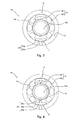
Fig. 2] Fig. 2 is a diagram taken along line I-I ofFig. 1 and shows a back surface of the valve plate incorporated in the axial piston hydraulic motor ofFig. 1 . - [
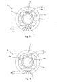
Fig. 3] Fig. 3 is a diagram corresponding to the diagram taken along line I-I ofFig. 1 and shows another embodiment of the valve plate used in the axial piston hydraulic motor. - [
Fig. 4] Fig. 4 is a diagram corresponding to the diagram taken along line I-I ofFig. 1 and shows yet another embodiment of the valve plate used in the axial piston hydraulic motor. - [
Fig. 5] Fig. 5 is a diagram corresponding to the diagram taken along line I-I ofFig. 1 and shows still another embodiment of the valve plate used in the axial piston hydraulic motor. - [
Fig. 6] Fig. 6 is a diagram corresponding to the diagram taken along line I-I ofFig. 1 and shows yet another embodiment of the valve plate used in the axial piston hydraulic motor. - [
Fig. 7] Fig. 7 is a diagram corresponding to the diagram taken along line I-I ofFig. 1 and shows still another embodiment of the valve plate used in the axial piston hydraulic motor. - [
Fig. 8] Fig. 8 is a diagram corresponding to the diagram taken along line I-I ofFig. 1 and shows an embodiment of the valve plate used in the axial piston hydraulic pump. - [
Fig. 9] Fig. 9 is a diagram corresponding to the diagram taken along line I-I ofFig. 1 and shows yet another embodiment of the valve plate used in the axial piston hydraulic pump. - [
Fig. 10] Fig. 10 is a diagram corresponding to the diagram taken along line I-I ofFig. 1 and shows still another embodiment of the valve plate used in the axial piston hydraulic pump. - [
Fig. 11] Fig. 11 is a longitudinal sectional view showing a swash plate type axial piston hydraulic pump including a conventional valve plate. - Embodiments of a valve plate of the present invention, an axial piston hydraulic motor including this valve plate, and an axial piston hydraulic pump including this valve plate will be explained in reference to the attached drawings.
-
Fig. 1 shows major portions of an axial piston hydraulic motor (hereinafter referred to as a "swash plate type motor") of one embodiment of the present invention. Acylinder block 3 is included in amotor housing 2 of a swashplate type motor 1. Amotor shaft 4 that is an output shaft is fixed to thecylinder block 3 along a central axis CL of thecylinder block 3. When thecylinder block 3 is rotated around the central axis CL, themotor shaft 4 also rotates. Arear end surface 3r of thecylinder block 3 contacts afront surface 5f of avalve plate 5 to be supported by thefront surface 5f of thevalve plate 5. Therefore, this front surface is also called a sliding supportingsurface 5f. Since a central throughhole 5a through which themotor shaft 4 penetrates is formed on a center portion of thevalve plate 5, theentire valve plate 5 has an annular shape (seeFig. 2 ). Thevalve plate 5 is supported such that a rear end portion thereof fits in a circular fitconcave portion 2a formed on an inner wall surface of themotor housing 2. An outer periphery of a surface (back surface) of the rear end portion of thevalve plate 5 is shallowly cut out, so that a gap G is formed between thevalve plate 5 and the surface of themotor housing 2. The hydraulic balance on the back surface of thevalve plate 5 is set by the area of a surface (hereinafter referred to as a "supportingsurface 5s") of the back surface, the surface contacting the surface of themotor housing 2. A whirl-stop pin 11 for preventing the rotation of thevalve plate 5 is put in the inner wall surface of themotor housing 2. - A plurality of
cylinders 6 are formed on thecylinder block 3 so as to be located around the central throughhole 5a and be parallel to one another.Pistons 7 are respectively inserted in thecylinders 6. Spherical portions of thepistons 7 are respectively coupled toshoes 7a. Theshoes 7a are pressed by aretainer plate 8 against ashoe plate 9a fixed to a swash plate 9. Theshoes 7a are rotatable together with thecylinder block 3 and thepistons 7 and are slidable with respect to the swash plate 9 and theshoe plate 9a.Ports 6a through which the operating oil is supplied to and discharged from thecylinders 6 are respectively formed on bottom portions of thecylinders 6 of thecylinder block 3. - As is clear from
Figs. 1 and 2 , a plurality ofports 10 are formed so as to penetrate thevalve plate 5 and respectively communicate with theports 6a of thecylinder block 3. In thevalve plate 5 shown inFig. 2 , threeleft ports 10L and threeright ports 10R are formed between an upper dead center U and lower dead center L of thevalve plate 5 so as to be arranged along a circumferential direction. Here, the number of ports is not limited to three. In a case where the left ports 1OL are oil supply ports and theright ports 10R are oil discharge ports, thecylinder block 3 rotates in a counterclockwise direction when viewed from a rear side (thevalve plate 5 side) of thecylinder block 3. In a case where theleft ports 10L are the oil discharge ports and theright ports 10R are the oil supply ports, thecylinder block 3 rotates in a clockwise direction. Of course, the pressure of the operating oil on the oil supply side is higher than that on the oil discharge side. An inner portion of themotor housing 2 is filled with the operating oil supplied to and discharged from thecylinders 6. - The
rear end surface 3r of thecylinder block 3 is pressed against the sliding supportingsurface 5f of thevalve plate 5 by the pressure of the operating oil in thecylinders 6, and thecylinder block 3 rotates in this state. The sliding supportingsurface 5f is a portion corresponding to the supportingsurface 5s of the above-described back surface. As shown inFigs. 1 and 2 , groove-shapedconcave portions 12 are respectively formed in the vicinity of the upper dead center U and lower dead center L on the supportingsurface 5s of thevalve plate 5. Theconcave portions 12 are formed for the purpose of cooling thevalve plate 5 by the operating oil flowing into theconcave portions 12. Each of theconcave portions 12 is constituted by: a circular-arc groove 12a formed along an outer peripheral circle of thevalve plate 5 in the vicinity of the outer periphery of thevalve plate 5; and aradial groove 12b formed to cause the circular-arc groove 12a to communicate with the central throughhole 5a. - As shown in
Fig. 1 , the relation between a depth t1 of the circular-arc groove 12a and a thickness T of a portion, where thegroove 12a is formed, of thevalve plate 5 is shown by a formula "t1 = 0.3 to 0.95T". - A surface on the
cylinder block 3 side of a bottom portion of theconcave portion 12 is formed to be included in the sliding supportingsurface 5f. - When the swash
plate type motor 1 is operating, the operating oil in low-pressure ports from thecylinders 6 flows through an operatingoil supply passage 19 into theconcave portion 12. Then, the operating oil flows out through theradial groove 12b to the central throughhole 5a. Although the frictional heat is generated on thevalve plate 5 by the sliding of thecylinder block 3, thevalve plate 5 is cooled by the operating oil flowing into theconcave portion 12. The thickness of the portion, where theconcave portion 12 is formed, of thevalve plate 5 is smaller than that of the other portion thereof. Therefore, the cooling effect is further effective. The reason why the circular-arc groove 12a is formed in the vicinity of the outer periphery of thevalve plate 5 so as to be spaced apart from the central throughhole 5a is as below. That is, since a relative rotating speed (circumferential speed) of an outer portion of the sliding supportingsurface 5f with respect to thecylinder block 3 is higher and this increases the amount of frictional heat generated at the outer portion, the circular-arc groove 12a is formed as above for the purpose of effectively cooling the outer portion of the sliding supportingsurface 5f. - Even if the operating
oil supply passage 19 cannot be formed, theconcave portion 12 is filled with the oil in themotor housing 2. Since the temperature of the oil in thehousing 2 is lower than the temperature of the sliding surface, the cooling effect can be obtained. - In
Fig. 1 , the depth of the circular-arc groove 12a and the depth of theradial groove 12b are slightly different from each other. However, the present embodiment is not limited to this. These depths of the grooves may be the same as each other, or theradial groove 12b may be deeper than the circular-arc groove 12a. -
Figs. 3 to 8 show coolingconcave portions valve plates Figs. 2 to 8 are valve plates used in the swash plate type motor. These coolingconcave portions concave portion 12 ofFig. 2 are formed at the upper dead centers U and lower dead centers L of thevalve plates 13 to 18. This is because since theports 10 are not formed at the upper dead center U and the lower dead center L, the frictional heat is less likely to dissipate and the temperature tends to increase at the upper dead center U and the lower dead center L as compared to the other portions. Further, this is because at the upper dead center U and the lower dead center L, there is an adequate space for forming the concave portion. Therefore, the cooling effect can be obtained even in a case where the concave portion is formed at only one of the upper dead center U and the lower dead center L. If possible, the concave portion may be formed between theleft ports 10L or between theright ports 10R, not at the upper dead center U and the lower dead center L. This is because the cooling effect can be obtained by forming the concave portion anywhere on the supporting surface. - The
concave portions 23 of thevalve plate 13 ofFig. 3 are respectively formed at the upper dead center U and lower dead center L of a supportingsurface 13s. Theconcave portion 23 is constituted by a circular-arc groove 23a formed along an outer peripheral circle of thevalve plate 13 and a shortradial groove 23b formed to cause the circular-arc groove 23a to communicate with themotor housing 2 located on an outer side of thevalve plate 13. The circular-arc groove 23a is formed in the vicinity of the outer periphery of thevalve plate 13. The operating oil in the low-pressure ports from thecylinders 6 flows through the operatingoil supply passage 19 into theconcave portion 23. Then, the operating oil flows out through theradial groove 23b to thehousing 2. - The
concave portion 24 of thevalve plate 14 ofFig. 4 is formed by adding to theconcave portion 23 ofFig. 3 a secondradial groove 24c extending toward an inner side of thevalve plate 14. Since the shapes of the other portions of theconcave portion 24 including a firstradial groove 24b are the same as those of theconcave portion 23 ofFig. 3 , similar reference signs are used for similar components, and detailed explanations thereof are omitted. The secondradial groove 24c extends from the center of the circular-arc groove 24a toward a central throughhole 14a located on the inner side of thevalve plate 14 but does not reach the central throughhole 14a. The secondradial groove 24c is formed for the purpose of effectively increasing the cooling area. - The concave portion 25 of the
valve plate 15 ofFig. 5 is formed by adding a plurality of secondradial grooves 25c to theconcave portion 23 ofFig. 3 , each of the secondradial grooves 25c being similar to the second radial groove explained inFig. 4 . Since the shapes of the other portions, such as a circular-arc groove 25a and a first radial groove 25b, are the same as those of the concave portion ofFig. 3 or 4 , similar reference signs are used for similar components, and detailed explanations thereof are omitted. The secondradial grooves 25c do not reach a central throughhole 15a. The secondradial grooves 25c are formed for the purpose of effectively increasing the cooling area. - The
concave portion 26 of thevalve plate 16 ofFig. 6 is formed such that the circular-arc groove 23a of theconcave portion 23 inFig. 3 is increased in width. Since the shapes of the other portions, such as aradial groove 26b, are the same as those of theconcave portion 23 ofFig. 3 , similar reference signs are used for similar components, and detailed explanations thereof are omitted. The width of the circular-arc groove 26a is about 1.5 to 2 times the width of each of the circular-arc grooves Figs. 2 to 5 . - The
concave portion 27 of thevalve plate 17 ofFig. 7 is formed such that instead of the circular-arc groove 23a ofFig. 3 , a plurality of circularconcave portions 27a arranged along an outer peripheral circle of thevalve plate 17 in the vicinity of the outer periphery of thevalve plate 17 are adopted. In addition, shortradial grooves 27b are formed for causing the circularconcave portions 27a located on both sides to communicate with themotor housing 2 located on an outer side of thevalve plate 17. - The
concave portion 28 of thevalve plate 18 ofFig. 8 is formed such that instead of a plurality of concave portions, only oneconcave portion 28a similar to the circular concave portion shown inFig. 7 is formed at each of the upper dead center U and the lower dead center L. In addition, a shortradial groove 28b similar to the radial groove shown inFig. 2 extends from each of the circularconcave portions 28a so as to communicate with a central throughhole 18a of thevalve plate 18. - The concave portions of the
valve plates Figs. 2 to 8 . However, the present embodiment is not limited to these. For example, the concave portion may be formed to communicate with both themotor housing 2 located on the outer side of the valve plate and the central through hole (5a and 13a to 18a), not one of themotor housing 2 and the central through hole (5a and 13a to 18a). Moreover, the concave portion may be formed only by the radial groove formed to cause themotor housing 2 located on the outer side of the valve plate and the central through hole (5a and 13a to 18a) to directly communicate with each other without forming the circular-arc groove. In contrast, a groove for aggressively causing the concave portion (the circular-arc groove and the radial groove) to communicate with themotor housing 2 located on the outer side of the valve plate and the central through hole (5a and 13a to 18a) does not have to be formed. Even in this case, the cooling effect can be obtained by the operating oil in the concave portion. In addition, the cooling effect can be obtained since a small amount of operating oil flows through an extremely narrow gap between the inner surface of themotor housing 2 and the supporting surface (5s and 13s to 18s) of the valve plate (5 and 13 to 18). To be specific, the cooling effect can be obtained only by forming the concave portion on the supportingsurface 5s regardless of the shape of the concave portion. - Moreover, a dedicated passage through which the operating oil is supplied to the concave portion may be formed instead of or in addition to the configuration in which the concave portion of the valve plate (5 and 13 to 18) communicates with the
motor housing 2 located on the outer side of the valve plate and/or the central through hole (5a and 13a to 18a). This dedicated passage is shown by a broken line inFig. 1 . To be specific, the operatingoil supply passage 19 is formed to have a tunnel shape in the wall of themotor housing 2. Although not shown, the operatingoil supply passage 19 is connected to the above-described low-pressure port oil supply passage 19 is formed so as to always receive the operating oil from a port that becomes a discharge port by a switching valve, not shown. The cooling effect improves by aggressively supplying the operating oil to the concave portion as above. - In the
valve plates motor housing 2 acts. Of course, if, for example, the decrease of the output efficiency is allowed, the cooling effect may be improved by causing the cooling concave portion to communicate with the port. -
Figs. 9 and 10 show supporting surfaces 20s and 21s ofvalve plates shoe 7a reciprocates in the cylinder. As above, the input and output of the swash plate type pump are opposite to those of the swash plate type motor. However, as with the swash plate type motor, the cylinder block of the swash plate type pump rotate in a state where the cylinder block is being pressed against the valve plate by the action of the internal pressure of the cylinders. As a result, the frictional heat is generated on the sliding surfaces of the valve plate and the cylinder block. These are explained in the Background Art of the present specification. - Operating oil suction and
ejection ports valve plates Figs. 9 and 10 . One right, long, circular-arc port 22R is the suction port, and threeleft ports 22L are the ejection ports. The shape of thesuction port 22R is different from that of theport 10R (Figs. 2 to 8 ) of the swash plate type motor. This is because since the operating oil on the suction side is low in pressure, the formation of thelong port 22R as shown does not cause strength problems on thevalve plates port 22L and theport 22L) is formed at the ports for the purpose of maintaining the strength of each of thevalve plates surfaces valve plates - A
concave portion 30 similar to theconcave portion 12 of thevalve plate 5 used in the motor shown inFig. 2 is formed on thevalve plate 20 ofFig. 9 . Each of theconcave portions 30 at the upper dead center U and the lower dead center L is constituted by a circular-arc groove 30a formed along the outer peripheral circle of thevalve plate 20 in the vicinity of the outer periphery of thevalve plate 20 and aradial groove 30b formed to cause the circular-arc groove 30a to communicate with a central throughhole 20a. However, one end of the circular-arc groove 30a communicates with thesuction port 22R. Therefore, the operating oil flows between thesuction port 22R and the central throughhole 20a through the circular-arc groove 30a and theradial groove 30b. In a case where theconcave portion 30 communicates with theport 22R where the amount of flow of the operating oil is large, the cooling effect of thevalve plate 20 improves as compared to a case where theconcave portion 30 communicates with only themotor housing 2 located on an outer side of thevalve plate 20 and the central throughhole 20a. Moreover, the reason why the circular-arc groove 30a communicates with not theejection port 22L but thesuction port 22R is because the pump efficiency decreases in a case where the circular-arc groove 30a communicates with theejection port 22L. - A
concave portion 31 of thevalve plate 21 shown inFig. 10 is constituted only by a circular-arc groove 31 a formed to communicate with thesuction port 22R. - The
concave portions valve plates Figs. 9 and 10 . However, the present embodiment is not limited to this. For example, each of theconcave portions valve plates Figs. 2 to 8 may be adopted as it is. Or, the concave portion formed by causing the circular-arc groove Fig. 3, 4 ,5, or 6 to communicate with thesuction port 22R may be adopted. Or, the concave portion formed by causing the secondradial groove Fig. 4 or5 to communicate with thesuction port 22R may be adopted. Or, the concave portion formed by causing the circularconcave portion Fig. 7 or 8 to communicate with thesuction port 22R may be adopted. - In the embodiment explained above, the swash plate type motor and the swash plate type pump are used as examples. However, the present embodiment is not limited to these. For example, the present invention is applicable to the bent axis type hydraulic motor and the bent axis type hydraulic pump.
- According to the present invention, the valve plate can be effectively cooled without depending on the adjustment of the amount of leakage oil. Therefore, the present invention is especially useful for the hydraulic motor and the hydraulic pump in which the further increase in the revolution and the further increase in the pressure of the operating oil are required.
-
- 1
- swash plate type motor
- 2
- motor housing
- 3
- cylinder block
- 4
- motor shaft
- 5
- valve plate
- 6
- cylinder
- 7
- piston
- 7a
- shoe
- 8
- retainer plate
- 9
- swash plate
- 9a
- shoe plate
- 10
- port
- 11
- whirl-stop pin
- 12
- concave portion
- 13 to 18
- valve plate
- 19
- operating oil supply passage
- 20, 21
- valve plate
- 22
- port
- 23 to 28
- concave portion
- 30, 31
- concave portion
- CL
- central axis (of cylinder block)
- G
- (gap on back surface of valve plate)
Claims (8)
- A valve plate used in an axial piston hydraulic device including a rotating shaft and a rotary cylinder block in a housing, the valve plate comprising:a sliding supporting surface configured to contact a rear end surface of the cylinder block to support the cylinder block;a back surface that is a surface corresponding to and opposite to the sliding supporting surface;a central hole through which the rotating shaft penetrates; anda plurality of ports formed around the central hole as inlets and outlets of operating oil so as to penetrate the valve plate, whereina cooling concave portion into which the operating oil flows is formed in a region except for the ports on the back surface.
- The valve plate according to claim 1, wherein:the ports are formed on both left and right sides of the central hole;the cooling concave portion is formed at at least one of upper and lower sides of the central hole; anda bottom portion of the cooling concave portion forms the sliding supporting surface.
- The valve plate according to claim 1 or 2, wherein a groove through which the operating oil flows and which causes the cooling concave portion to communicate with at least one of the central hole located on an inner side of the valve plate and an inner space of the housing located on an outer side of the valve plate is formed on the back surface.
- The valve plate according to claim 1, wherein the cooling concave portion is constituted by a groove configured on the back surface to cause the central hole located on an inner side of the valve plate and an inner space of the housing located on an outer side of the valve plate to communicate with each other.
- The valve plate according to claim 1, wherein:the hydraulic device is an axial piston hydraulic pump; anda groove through which the operating oil flows and which causes the cooling concave portion to communicate with an operating oil suction port among the ports is formed on the back surface.
- The valve plate according to claim 1, wherein:the hydraulic device is an axial piston hydraulic motor; andan operating oil supply passage configured to communicate with an operating oil discharge port among the ports is connected to the cooling concave portion.
- An axial piston hydraulic pump comprising a valve plate, wherein:the valve plate is the valve plate according to claim 1;the rotating shaft is a driving shaft configured to cause the cylinder block to rotate; andthe plurality of ports are suction ports and ejection ports of the operating oil.
- An axial piston hydraulic motor comprising a valve plate, wherein:the valve plate is the valve plate according to claim 1;the rotating shaft is a motor shaft configured to be rotated by rotation of the cylinder block; andthe plurality of ports are supply ports and discharge ports of the operating oil, the supply ports and the discharge ports being alternately switched by switching a rotational direction of the motor.
Applications Claiming Priority (2)
| Application Number | Priority Date | Filing Date | Title |
|---|---|---|---|
| JP2010080588A JP5444088B2 (en) | 2010-03-31 | 2010-03-31 | Valve plate and axial piston type hydraulic pump / motor equipped with the same |
| PCT/JP2011/001060 WO2011121883A1 (en) | 2010-03-31 | 2011-02-24 | Valve plate, and axial piston hydraulic pump and axial piston hydraulic motor with same |
Publications (3)
| Publication Number | Publication Date |
|---|---|
| EP2554842A1 true EP2554842A1 (en) | 2013-02-06 |
| EP2554842A4 EP2554842A4 (en) | 2018-01-24 |
| EP2554842B1 EP2554842B1 (en) | 2020-04-15 |
Family
ID=44711654
Family Applications (1)
| Application Number | Title | Priority Date | Filing Date |
|---|---|---|---|
| EP11762137.5A Active EP2554842B1 (en) | 2010-03-31 | 2011-02-24 | Valve plate, and axial piston hydraulic pump and axial piston hydraulic motor with same |
Country Status (6)
| Country | Link |
|---|---|
| US (1) | US9175672B2 (en) |
| EP (1) | EP2554842B1 (en) |
| JP (1) | JP5444088B2 (en) |
| KR (1) | KR101390584B1 (en) |
| CN (1) | CN102812243B (en) |
| WO (1) | WO2011121883A1 (en) |
Families Citing this family (19)
| Publication number | Priority date | Publication date | Assignee | Title |
|---|---|---|---|---|
| JP6110074B2 (en) * | 2012-03-30 | 2017-04-05 | 三菱重工業株式会社 | Fluid pressure pump |
| CN102865251B (en) * | 2012-09-10 | 2014-12-24 | 江苏大学 | Suspension body of hot water circulating pump provided with groove structure on inner wall surface |
| JP2014126020A (en) * | 2012-12-27 | 2014-07-07 | Kawasaki Heavy Ind Ltd | Axial piston motor |
| US9657726B1 (en) | 2013-04-19 | 2017-05-23 | Hydro-Gear Limited Partnership | Hydraulic running surface |
| DE102014207158A1 (en) * | 2013-12-12 | 2015-06-18 | Robert Bosch Gmbh | Hydrostatic axial piston machine |
| JP2015166580A (en) * | 2014-03-04 | 2015-09-24 | 株式会社豊田自動織機 | Compressor |
| CN105201816B (en) * | 2015-09-07 | 2017-03-22 | 福州大学 | Self-cooling structure for cylinder of swashplate type plunger pump |
| SG10202109691UA (en) | 2016-04-15 | 2021-10-28 | Alder Biopharmaceuticals Inc | Anti-pacap antibodies and uses thereof |
| JP2018076826A (en) * | 2016-11-10 | 2018-05-17 | 川崎重工業株式会社 | Cylinder block and swash plate type fluid pressure rotation device including the same |
| CN107965449B (en) * | 2017-12-28 | 2019-03-29 | 赛克思液压科技股份有限公司 | A structure for anti-stripping of plunger pump |
| JP7374638B2 (en) | 2019-07-18 | 2023-11-07 | ナブテスコ株式会社 | Fluid machinery and construction machinery |
| JP2021032212A (en) * | 2019-08-29 | 2021-03-01 | ナブテスコ株式会社 | Hydraulic pump and construction machine |
| JP7476060B2 (en) * | 2020-09-14 | 2024-04-30 | 株式会社小松製作所 | Valve plates, cylinder blocks, hydraulic motors |
| US11898582B1 (en) * | 2023-03-09 | 2024-02-13 | Dana Motion Systems Italia S.R.L. | System for a bent axis motor |
| US12516662B2 (en) | 2023-03-22 | 2026-01-06 | Dana Motion Systems Italia S.R.L. | Actuation system for a motor |
| US12601332B2 (en) | 2023-07-07 | 2026-04-14 | Robert Bosch Gmbh | Integrated electro-hydraulic unit |
| US12031559B1 (en) | 2023-07-07 | 2024-07-09 | Robert Bosch Gmbh | Integrated electro-hydraulic unit |
| US12435711B2 (en) | 2023-09-12 | 2025-10-07 | Robert Bosch Gmbh | Integrated electro-hydraulic unit housing |
| WO2026120069A1 (en) | 2024-12-05 | 2026-06-11 | H. Lundbeck A/S | Humanized anti-pacap antibody and uses thereof |
Family Cites Families (17)
| Publication number | Priority date | Publication date | Assignee | Title |
|---|---|---|---|---|
| JPS4119713Y1 (en) * | 1964-07-23 | 1966-09-16 | ||
| JPS467854B1 (en) * | 1965-11-10 | 1971-02-27 | ||
| DE2641158A1 (en) * | 1975-09-15 | 1977-03-24 | Maszyn Budowlanych Bumar Fabry | Axial pistn lubricating pump - has pistons with concave spherical faces on convex hollow joints driven by ball jointed shaft |
| GB2056576A (en) * | 1979-08-20 | 1981-03-18 | Commercial Shearing | Piston pumps and motors |
| JPS6014053U (en) | 1983-07-08 | 1985-01-30 | 岡部株式会社 | Spacing member for concrete formwork |
| US4887755A (en) | 1989-02-07 | 1989-12-19 | Merck & Co., Inc. | Adjustable tablet breaking apparatus |
| JPH04219473A (en) * | 1990-04-06 | 1992-08-10 | Zexel Corp | Axial swash plate type variable displacement pump |
| US5105723A (en) * | 1990-04-06 | 1992-04-21 | Zexel Corporation | Swash plate type axial piston pump |
| JPH0440169U (en) * | 1990-08-01 | 1992-04-06 | ||
| JPH0733083B2 (en) | 1992-02-14 | 1995-04-12 | 日本シイエムケイ株式会社 | Gauze peeling device stretched on the gauze frame used for silk printing |
| JPH0722076U (en) * | 1993-09-16 | 1995-04-21 | 川崎重工業株式会社 | Rotary piston pump |
| JP3771004B2 (en) | 1997-07-03 | 2006-04-26 | カヤバ工業株式会社 | Axial piston motor |
| JPH11241674A (en) * | 1998-02-24 | 1999-09-07 | Nabco Ltd | Swash plate hydraulic motor |
| JP4562877B2 (en) * | 2000-07-25 | 2010-10-13 | 東芝機械株式会社 | Swash plate type piston motor |
| JP4577969B2 (en) * | 2000-09-26 | 2010-11-10 | 三輪精機株式会社 | Hydraulic motor |
| JP2002349423A (en) | 2001-05-25 | 2002-12-04 | Takako:Kk | Oblique axial piston pump / motor |
| JP2003003949A (en) | 2001-06-20 | 2003-01-08 | Kawasaki Heavy Ind Ltd | Swash plate pump |
-
2010
- 2010-03-31 JP JP2010080588A patent/JP5444088B2/en active Active
-
2011
- 2011-02-24 EP EP11762137.5A patent/EP2554842B1/en active Active
- 2011-02-24 KR KR1020127015977A patent/KR101390584B1/en active Active
- 2011-02-24 US US13/582,310 patent/US9175672B2/en active Active
- 2011-02-24 CN CN201180016119.2A patent/CN102812243B/en active Active
- 2011-02-24 WO PCT/JP2011/001060 patent/WO2011121883A1/en not_active Ceased
Non-Patent Citations (1)
| Title |
|---|
| See references of WO2011121883A1 * |
Also Published As
| Publication number | Publication date |
|---|---|
| CN102812243A (en) | 2012-12-05 |
| US20130055888A1 (en) | 2013-03-07 |
| US9175672B2 (en) | 2015-11-03 |
| JP5444088B2 (en) | 2014-03-19 |
| KR20120096013A (en) | 2012-08-29 |
| EP2554842A4 (en) | 2018-01-24 |
| EP2554842B1 (en) | 2020-04-15 |
| KR101390584B1 (en) | 2014-04-30 |
| WO2011121883A1 (en) | 2011-10-06 |
| CN102812243B (en) | 2015-05-06 |
| JP2011214429A (en) | 2011-10-27 |
Similar Documents
| Publication | Publication Date | Title |
|---|---|---|
| EP2554842B1 (en) | Valve plate, and axial piston hydraulic pump and axial piston hydraulic motor with same | |
| US10145367B2 (en) | Piston pump and valve plate of piston pump | |
| EP2642123A1 (en) | Cooling structure for cylinder block and swash plate-type hydraulic device equipped with same | |
| EP3168470A1 (en) | Hydraulic rotary machine | |
| JP5846012B2 (en) | Swash plate compressor | |
| EP2940291A1 (en) | Axial piston motor | |
| JP5307514B2 (en) | Hydraulic piston pump / motor | |
| EP2778410B1 (en) | Hydraulic rotary machine | |
| WO2018088487A1 (en) | Cylinder block, and swashplate type hydraulic rotating device provided with same | |
| JP2015117579A (en) | Hydraulic rotary machine and work machinery including hydraulic rotary machine | |
| JP6913260B2 (en) | Cylinder block and swash plate hydraulic rotary device equipped with it | |
| JP2026044622A (en) | Piston pump | |
| JP2024115194A (en) | Hydraulic rotary machine, cylinder block of hydraulic rotary machine, and valve plate of hydraulic rotary machine | |
| JP2013029072A (en) | Swash plate type piston pump | |
| JP2010133308A (en) | Double head piston compressor | |
| JP2015094222A (en) | Hydraulic piston pump / motor |
Legal Events
| Date | Code | Title | Description |
|---|---|---|---|
| PUAI | Public reference made under article 153(3) epc to a published international application that has entered the european phase |
Free format text: ORIGINAL CODE: 0009012 |
|
| 17P | Request for examination filed |
Effective date: 20120917 |
|
| AK | Designated contracting states |
Kind code of ref document: A1 Designated state(s): AL AT BE BG CH CY CZ DE DK EE ES FI FR GB GR HR HU IE IS IT LI LT LU LV MC MK MT NL NO PL PT RO RS SE SI SK SM TR |
|
| DAX | Request for extension of the european patent (deleted) | ||
| REG | Reference to a national code |
Ref country code: DE Ref legal event code: R079 Ref document number: 602011066271 Country of ref document: DE Free format text: PREVIOUS MAIN CLASS: F04B0001220000 Ipc: F04B0001200000 |
|
| RA4 | Supplementary search report drawn up and despatched (corrected) |
Effective date: 20171222 |
|
| RIC1 | Information provided on ipc code assigned before grant |
Ipc: F04B 1/20 20060101AFI20171218BHEP Ipc: F01B 3/00 20060101ALI20171218BHEP |
|
| STAA | Information on the status of an ep patent application or granted ep patent |
Free format text: STATUS: EXAMINATION IS IN PROGRESS |
|
| 17Q | First examination report despatched |
Effective date: 20190722 |
|
| GRAP | Despatch of communication of intention to grant a patent |
Free format text: ORIGINAL CODE: EPIDOSNIGR1 |
|
| STAA | Information on the status of an ep patent application or granted ep patent |
Free format text: STATUS: GRANT OF PATENT IS INTENDED |
|
| INTG | Intention to grant announced |
Effective date: 20200117 |
|
| GRAS | Grant fee paid |
Free format text: ORIGINAL CODE: EPIDOSNIGR3 |
|
| GRAA | (expected) grant |
Free format text: ORIGINAL CODE: 0009210 |
|
| STAA | Information on the status of an ep patent application or granted ep patent |
Free format text: STATUS: THE PATENT HAS BEEN GRANTED |
|
| AK | Designated contracting states |
Kind code of ref document: B1 Designated state(s): AL AT BE BG CH CY CZ DE DK EE ES FI FR GB GR HR HU IE IS IT LI LT LU LV MC MK MT NL NO PL PT RO RS SE SI SK SM TR |
|
| REG | Reference to a national code |
Ref country code: GB Ref legal event code: FG4D Ref country code: CH Ref legal event code: EP |
|
| REG | Reference to a national code |
Ref country code: DE Ref legal event code: R096 Ref document number: 602011066271 Country of ref document: DE |
|
| REG | Reference to a national code |
Ref country code: IE Ref legal event code: FG4D |
|
| REG | Reference to a national code |
Ref country code: AT Ref legal event code: REF Ref document number: 1257602 Country of ref document: AT Kind code of ref document: T Effective date: 20200515 |
|
| REG | Reference to a national code |
Ref country code: NL Ref legal event code: MP Effective date: 20200415 |
|
| REG | Reference to a national code |
Ref country code: LT Ref legal event code: MG4D |
|
| PG25 | Lapsed in a contracting state [announced via postgrant information from national office to epo] |
Ref country code: LT Free format text: LAPSE BECAUSE OF FAILURE TO SUBMIT A TRANSLATION OF THE DESCRIPTION OR TO PAY THE FEE WITHIN THE PRESCRIBED TIME-LIMIT Effective date: 20200415 Ref country code: PT Free format text: LAPSE BECAUSE OF FAILURE TO SUBMIT A TRANSLATION OF THE DESCRIPTION OR TO PAY THE FEE WITHIN THE PRESCRIBED TIME-LIMIT Effective date: 20200817 Ref country code: NL Free format text: LAPSE BECAUSE OF FAILURE TO SUBMIT A TRANSLATION OF THE DESCRIPTION OR TO PAY THE FEE WITHIN THE PRESCRIBED TIME-LIMIT Effective date: 20200415 Ref country code: SE Free format text: LAPSE BECAUSE OF FAILURE TO SUBMIT A TRANSLATION OF THE DESCRIPTION OR TO PAY THE FEE WITHIN THE PRESCRIBED TIME-LIMIT Effective date: 20200415 Ref country code: FI Free format text: LAPSE BECAUSE OF FAILURE TO SUBMIT A TRANSLATION OF THE DESCRIPTION OR TO PAY THE FEE WITHIN THE PRESCRIBED TIME-LIMIT Effective date: 20200415 Ref country code: GR Free format text: LAPSE BECAUSE OF FAILURE TO SUBMIT A TRANSLATION OF THE DESCRIPTION OR TO PAY THE FEE WITHIN THE PRESCRIBED TIME-LIMIT Effective date: 20200716 Ref country code: NO Free format text: LAPSE BECAUSE OF FAILURE TO SUBMIT A TRANSLATION OF THE DESCRIPTION OR TO PAY THE FEE WITHIN THE PRESCRIBED TIME-LIMIT Effective date: 20200715 Ref country code: IS Free format text: LAPSE BECAUSE OF FAILURE TO SUBMIT A TRANSLATION OF THE DESCRIPTION OR TO PAY THE FEE WITHIN THE PRESCRIBED TIME-LIMIT Effective date: 20200815 |
|
| REG | Reference to a national code |
Ref country code: AT Ref legal event code: MK05 Ref document number: 1257602 Country of ref document: AT Kind code of ref document: T Effective date: 20200415 |
|
| PG25 | Lapsed in a contracting state [announced via postgrant information from national office to epo] |
Ref country code: HR Free format text: LAPSE BECAUSE OF FAILURE TO SUBMIT A TRANSLATION OF THE DESCRIPTION OR TO PAY THE FEE WITHIN THE PRESCRIBED TIME-LIMIT Effective date: 20200415 Ref country code: LV Free format text: LAPSE BECAUSE OF FAILURE TO SUBMIT A TRANSLATION OF THE DESCRIPTION OR TO PAY THE FEE WITHIN THE PRESCRIBED TIME-LIMIT Effective date: 20200415 Ref country code: RS Free format text: LAPSE BECAUSE OF FAILURE TO SUBMIT A TRANSLATION OF THE DESCRIPTION OR TO PAY THE FEE WITHIN THE PRESCRIBED TIME-LIMIT Effective date: 20200415 Ref country code: BG Free format text: LAPSE BECAUSE OF FAILURE TO SUBMIT A TRANSLATION OF THE DESCRIPTION OR TO PAY THE FEE WITHIN THE PRESCRIBED TIME-LIMIT Effective date: 20200715 |
|
| PG25 | Lapsed in a contracting state [announced via postgrant information from national office to epo] |
Ref country code: AL Free format text: LAPSE BECAUSE OF FAILURE TO SUBMIT A TRANSLATION OF THE DESCRIPTION OR TO PAY THE FEE WITHIN THE PRESCRIBED TIME-LIMIT Effective date: 20200415 |
|
| REG | Reference to a national code |
Ref country code: DE Ref legal event code: R097 Ref document number: 602011066271 Country of ref document: DE |
|
| PG25 | Lapsed in a contracting state [announced via postgrant information from national office to epo] |
Ref country code: ES Free format text: LAPSE BECAUSE OF FAILURE TO SUBMIT A TRANSLATION OF THE DESCRIPTION OR TO PAY THE FEE WITHIN THE PRESCRIBED TIME-LIMIT Effective date: 20200415 Ref country code: CZ Free format text: LAPSE BECAUSE OF FAILURE TO SUBMIT A TRANSLATION OF THE DESCRIPTION OR TO PAY THE FEE WITHIN THE PRESCRIBED TIME-LIMIT Effective date: 20200415 Ref country code: RO Free format text: LAPSE BECAUSE OF FAILURE TO SUBMIT A TRANSLATION OF THE DESCRIPTION OR TO PAY THE FEE WITHIN THE PRESCRIBED TIME-LIMIT Effective date: 20200415 Ref country code: DK Free format text: LAPSE BECAUSE OF FAILURE TO SUBMIT A TRANSLATION OF THE DESCRIPTION OR TO PAY THE FEE WITHIN THE PRESCRIBED TIME-LIMIT Effective date: 20200415 Ref country code: EE Free format text: LAPSE BECAUSE OF FAILURE TO SUBMIT A TRANSLATION OF THE DESCRIPTION OR TO PAY THE FEE WITHIN THE PRESCRIBED TIME-LIMIT Effective date: 20200415 Ref country code: SM Free format text: LAPSE BECAUSE OF FAILURE TO SUBMIT A TRANSLATION OF THE DESCRIPTION OR TO PAY THE FEE WITHIN THE PRESCRIBED TIME-LIMIT Effective date: 20200415 Ref country code: AT Free format text: LAPSE BECAUSE OF FAILURE TO SUBMIT A TRANSLATION OF THE DESCRIPTION OR TO PAY THE FEE WITHIN THE PRESCRIBED TIME-LIMIT Effective date: 20200415 |
|
| PLBE | No opposition filed within time limit |
Free format text: ORIGINAL CODE: 0009261 |
|
| STAA | Information on the status of an ep patent application or granted ep patent |
Free format text: STATUS: NO OPPOSITION FILED WITHIN TIME LIMIT |
|
| PG25 | Lapsed in a contracting state [announced via postgrant information from national office to epo] |
Ref country code: SK Free format text: LAPSE BECAUSE OF FAILURE TO SUBMIT A TRANSLATION OF THE DESCRIPTION OR TO PAY THE FEE WITHIN THE PRESCRIBED TIME-LIMIT Effective date: 20200415 Ref country code: PL Free format text: LAPSE BECAUSE OF FAILURE TO SUBMIT A TRANSLATION OF THE DESCRIPTION OR TO PAY THE FEE WITHIN THE PRESCRIBED TIME-LIMIT Effective date: 20200415 |
|
| 26N | No opposition filed |
Effective date: 20210118 |
|
| PG25 | Lapsed in a contracting state [announced via postgrant information from national office to epo] |
Ref country code: SI Free format text: LAPSE BECAUSE OF FAILURE TO SUBMIT A TRANSLATION OF THE DESCRIPTION OR TO PAY THE FEE WITHIN THE PRESCRIBED TIME-LIMIT Effective date: 20200415 |
|
| PG25 | Lapsed in a contracting state [announced via postgrant information from national office to epo] |
Ref country code: MC Free format text: LAPSE BECAUSE OF FAILURE TO SUBMIT A TRANSLATION OF THE DESCRIPTION OR TO PAY THE FEE WITHIN THE PRESCRIBED TIME-LIMIT Effective date: 20200415 |
|
| REG | Reference to a national code |
Ref country code: BE Ref legal event code: MM Effective date: 20210228 |
|
| PG25 | Lapsed in a contracting state [announced via postgrant information from national office to epo] |
Ref country code: CH Free format text: LAPSE BECAUSE OF NON-PAYMENT OF DUE FEES Effective date: 20210228 Ref country code: LU Free format text: LAPSE BECAUSE OF NON-PAYMENT OF DUE FEES Effective date: 20210224 Ref country code: LI Free format text: LAPSE BECAUSE OF NON-PAYMENT OF DUE FEES Effective date: 20210228 |
|
| PG25 | Lapsed in a contracting state [announced via postgrant information from national office to epo] |
Ref country code: IE Free format text: LAPSE BECAUSE OF NON-PAYMENT OF DUE FEES Effective date: 20210224 |
|
| PG25 | Lapsed in a contracting state [announced via postgrant information from national office to epo] |
Ref country code: BE Free format text: LAPSE BECAUSE OF NON-PAYMENT OF DUE FEES Effective date: 20210228 |
|
| PG25 | Lapsed in a contracting state [announced via postgrant information from national office to epo] |
Ref country code: HU Free format text: LAPSE BECAUSE OF FAILURE TO SUBMIT A TRANSLATION OF THE DESCRIPTION OR TO PAY THE FEE WITHIN THE PRESCRIBED TIME-LIMIT; INVALID AB INITIO Effective date: 20110224 Ref country code: CY Free format text: LAPSE BECAUSE OF FAILURE TO SUBMIT A TRANSLATION OF THE DESCRIPTION OR TO PAY THE FEE WITHIN THE PRESCRIBED TIME-LIMIT Effective date: 20200415 |
|
| PG25 | Lapsed in a contracting state [announced via postgrant information from national office to epo] |
Ref country code: MK Free format text: LAPSE BECAUSE OF FAILURE TO SUBMIT A TRANSLATION OF THE DESCRIPTION OR TO PAY THE FEE WITHIN THE PRESCRIBED TIME-LIMIT Effective date: 20200415 |
|
| PG25 | Lapsed in a contracting state [announced via postgrant information from national office to epo] |
Ref country code: TR Free format text: LAPSE BECAUSE OF FAILURE TO SUBMIT A TRANSLATION OF THE DESCRIPTION OR TO PAY THE FEE WITHIN THE PRESCRIBED TIME-LIMIT Effective date: 20200415 |
|
| PG25 | Lapsed in a contracting state [announced via postgrant information from national office to epo] |
Ref country code: MT Free format text: LAPSE BECAUSE OF FAILURE TO SUBMIT A TRANSLATION OF THE DESCRIPTION OR TO PAY THE FEE WITHIN THE PRESCRIBED TIME-LIMIT Effective date: 20200415 |
|
| PGFP | Annual fee paid to national office [announced via postgrant information from national office to epo] |
Ref country code: FR Payment date: 20251231 Year of fee payment: 16 |
|
| PGFP | Annual fee paid to national office [announced via postgrant information from national office to epo] |
Ref country code: GB Payment date: 20260106 Year of fee payment: 16 |
|
| PGFP | Annual fee paid to national office [announced via postgrant information from national office to epo] |
Ref country code: DE Payment date: 20260102 Year of fee payment: 16 |
|
| PGFP | Annual fee paid to national office [announced via postgrant information from national office to epo] |
Ref country code: IT Payment date: 20260122 Year of fee payment: 16 |