EP2554794A2 - Leitschaufelanordnung für eine Gasturbinentriebwerk - Google Patents
Leitschaufelanordnung für eine Gasturbinentriebwerk Download PDFInfo
- Publication number
- EP2554794A2 EP2554794A2 EP12179027A EP12179027A EP2554794A2 EP 2554794 A2 EP2554794 A2 EP 2554794A2 EP 12179027 A EP12179027 A EP 12179027A EP 12179027 A EP12179027 A EP 12179027A EP 2554794 A2 EP2554794 A2 EP 2554794A2
- Authority
- EP
- European Patent Office
- Prior art keywords
- platform
- airfoil
- assembly
- recited
- variable
- Prior art date
- Legal status (The legal status is an assumption and is not a legal conclusion. Google has not performed a legal analysis and makes no representation as to the accuracy of the status listed.)
- Granted
Links
- 238000000034 method Methods 0.000 claims description 4
- 239000007789 gas Substances 0.000 description 26
- 230000000712 assembly Effects 0.000 description 10
- 238000000429 assembly Methods 0.000 description 10
- 239000000567 combustion gas Substances 0.000 description 5
- 239000000284 extract Substances 0.000 description 5
- 239000011295 pitch Substances 0.000 description 3
- 239000000446 fuel Substances 0.000 description 2
- 238000012986 modification Methods 0.000 description 1
- 230000004048 modification Effects 0.000 description 1
- 238000005192 partition Methods 0.000 description 1
- 230000003068 static effect Effects 0.000 description 1
Images

Classifications
-
- F—MECHANICAL ENGINEERING; LIGHTING; HEATING; WEAPONS; BLASTING
- F01—MACHINES OR ENGINES IN GENERAL; ENGINE PLANTS IN GENERAL; STEAM ENGINES
- F01D—NON-POSITIVE DISPLACEMENT MACHINES OR ENGINES, e.g. STEAM TURBINES
- F01D9/00—Stators
- F01D9/02—Nozzles; Nozzle boxes; Stator blades; Guide conduits, e.g. individual nozzles
- F01D9/04—Nozzles; Nozzle boxes; Stator blades; Guide conduits, e.g. individual nozzles forming ring or sector
- F01D9/041—Nozzles; Nozzle boxes; Stator blades; Guide conduits, e.g. individual nozzles forming ring or sector using blades
-
- F—MECHANICAL ENGINEERING; LIGHTING; HEATING; WEAPONS; BLASTING
- F01—MACHINES OR ENGINES IN GENERAL; ENGINE PLANTS IN GENERAL; STEAM ENGINES
- F01D—NON-POSITIVE DISPLACEMENT MACHINES OR ENGINES, e.g. STEAM TURBINES
- F01D17/00—Regulating or controlling by varying flow
- F01D17/10—Final actuators
- F01D17/12—Final actuators arranged in stator parts
- F01D17/14—Final actuators arranged in stator parts varying effective cross-sectional area of nozzles or guide conduits
- F01D17/16—Final actuators arranged in stator parts varying effective cross-sectional area of nozzles or guide conduits by means of nozzle vanes
- F01D17/162—Final actuators arranged in stator parts varying effective cross-sectional area of nozzles or guide conduits by means of nozzle vanes for axial flow, i.e. the vanes turning around axes which are essentially perpendicular to the rotor centre line
-
- F—MECHANICAL ENGINEERING; LIGHTING; HEATING; WEAPONS; BLASTING
- F05—INDEXING SCHEMES RELATING TO ENGINES OR PUMPS IN VARIOUS SUBCLASSES OF CLASSES F01-F04
- F05D—INDEXING SCHEME FOR ASPECTS RELATING TO NON-POSITIVE-DISPLACEMENT MACHINES OR ENGINES, GAS-TURBINES OR JET-PROPULSION PLANTS
- F05D2250/00—Geometry
- F05D2250/30—Arrangement of components
-
- F—MECHANICAL ENGINEERING; LIGHTING; HEATING; WEAPONS; BLASTING
- F05—INDEXING SCHEMES RELATING TO ENGINES OR PUMPS IN VARIOUS SUBCLASSES OF CLASSES F01-F04
- F05D—INDEXING SCHEME FOR ASPECTS RELATING TO NON-POSITIVE-DISPLACEMENT MACHINES OR ENGINES, GAS-TURBINES OR JET-PROPULSION PLANTS
- F05D2250/00—Geometry
- F05D2250/70—Shape
- F05D2250/73—Shape asymmetric
-
- Y—GENERAL TAGGING OF NEW TECHNOLOGICAL DEVELOPMENTS; GENERAL TAGGING OF CROSS-SECTIONAL TECHNOLOGIES SPANNING OVER SEVERAL SECTIONS OF THE IPC; TECHNICAL SUBJECTS COVERED BY FORMER USPC CROSS-REFERENCE ART COLLECTIONS [XRACs] AND DIGESTS
- Y10—TECHNICAL SUBJECTS COVERED BY FORMER USPC
- Y10T—TECHNICAL SUBJECTS COVERED BY FORMER US CLASSIFICATION
- Y10T29/00—Metal working
- Y10T29/49—Method of mechanical manufacture
- Y10T29/49229—Prime mover or fluid pump making
Definitions
- This disclosure relates to a gas turbine engine, and more particularly to a vane assembly for a gas turbine engine.
- Gas turbine engines such as those which power modem commercial and military aircraft, typically include a compressor section, a combustor section and a turbine section. During operation, air is pressurized in the compressor section and is mixed with fuel and burned in the combustor section to generate hot combustion gases. The hot combustion gases are communicated through the turbine section which extracts energy from the hot combustion gases to power the compressor section and other gas turbine engine loads.
- the compressor section and the turbine section of the gas turbine engine typically include alternating rows of rotating blades and stationary vanes.
- the rotating blades create or extract energy from the airflow that is communicated through the gas turbine engine, and the stationary vanes direct the airflow to a downstream row of blades.
- the plurality of vanes of each stage are annularly disposed and can be mechanically attached to form a full ring vane assembly.
- the vane assembly can include both stationary vanes and variable vanes.
- a vane assembly for a gas turbine engine includes a first platform, a second platform and an airfoil that extends radially across an annulus between the first platform and the second platform.
- the airfoil is centered relative to a centerline axis of the second platform and is offset relative to a centerline axis of the first platform.
- a vane assembly for a gas turbine engine includes a first platform, a second platform and a variable airfoil that extends between the first platform and the second platform.
- the first platform is skewed relative to the second platform such that a first portion of the variable airfoil is positioned entirely on a gas path of the first platform and a second portion of the variable airfoil extends beyond a mate face of the second platform.
- a method for providing a vane assembly for a gas turbine engine includes skewing a first platform of the vane assembly relative to a second platform of the vane assembly.
- Figure 1 illustrates an example gas turbine 10 that is circumferentially disposed about an engine centerline axis A.
- the gas turbine engine 10 includes (in serial flow communication) a fan section 12, a compressor section 14, a combustor section 16, and a turbine section 18.
- air is compressed in the compressor section 14 and is mixed with fuel and burned in the combustor section 16.
- the combustion gases generated in the combustor section 16 are discharged through the turbine section 18, which extracts energy from the combustion gases to power the compressor section 14, the fan section 12 and other gas turbine engine loads.
- the compressor section 14 and the turbine section 18 include alternating rows of rotor assemblies 21 and vane assemblies 23.
- the rotor assemblies 21 include a plurality of rotating blades 20, and each vane assembly 23 includes a plurality of vanes 22.
- the blades 20 of the rotor assemblies 21 create or extract energy (in the form of pressure) from the airflow that is communicated through the gas turbine engine 10.
- the vanes 22 direct airflow to the blades 20 to either add or extract energy.
- This view is highly schematic and is included to provide a basic understanding of a gas turbine engine rather than limit the disclosure. This disclosure extends to all types of gas turbine engines and for all types of applications.
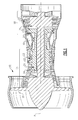
- Figure 2 illustrates an example vane assembly 23 of the gas turbine engine 10.
- the vane assembly 23 is a vane assembly of the turbine section 18.
- the vane assembly 23 could be incorporated into other sections of a gas turbine engine 10, including but not limited to, the compressor section 14.
- a plurality of vane assemblies are mechanically attached to one another and annularly disposed about the engine centerline axis A to form a full ring vane assembly.
- the vane assembly 23 can include either fixed vanes (i.e., static vanes), variable vanes that rotate to change a flow area associated with the vane, or both, as is discussed in greater detail below.
- the vane assembly 23 includes a first platform 34 and a second platform 36.
- One of the first platform 34 and the second platform 36 is positioned on an inner diameter side 35 of the vane assembly 23 and the other of the first platform 34 and the second platform 36 is positioned on an outer diameter side 37 of the vane assembly 23.
- a stationary airfoil 38 and variable airfoils 39A, 39B extend in span between the first platform 34 and the second platform 36. In other words, the stationary airfoil 38 and the variable airfoils 39A, 39B extend radially across an annulus 100 between the first platform 34 and the second platform 36.
- the first platform 34 and the second platform 36 each include a leading edge rail 40, a trailing edge rail 42, and opposing mate faces 44, 46 that extend axially between the leading edge rails 40 and the trailing edge rails 42. Airflow AF is communicated in a direction from the leading edge rail 40 toward the trailing edge rail 42 during engine operation.
- Additional vane assemblies 25A, 25B are positioned adjacent to the vane assembly 23, with the vane assembly 25A positioned at a first side 41 of the vane assembly 23 and the vane assembly 25B positioned on an opposite, second side 43 of the vane assembly 23.
- a plurality of vane assemblies can be annularly disposed about the engine centerline axis A to form a full ring vane assembly.
- the adjacent vane assemblies 23, 25A and 25B can be mechanically attached (e.g., bolted together) at the second platforms 36. It should be understood that an opposite configuration is contemplated in which the first platforms 34 are mechanically attached and the second platforms 36 are uncoupled.
- a split line 48 (i.e., partition) is established between the adjacent vane assemblies 23, 25A and 25B.
- a radially outer surface 50 of the first platform 34 defines a gas path 51 of the first platform 34, and a radially inner surface 52 of the second platform 36 establishes a gas path 53 of the second platform 36.
- the gas paths 51, 53 of the first platform 34 and the second platform 36 extend across an entirety of the radially outer surface 50 and the radially inner surface 52 of the first and second platforms 34, 36, respectively.
- the stationary airfoil 38 is integrally formed with at least one of (or both) the first platform 34 and the second platform 36. Therefore, the first platform 34 and the second platform 36 of the vane assembly 23 are coupled relative to one another.
- the variable airfoils 39A, 39B rotate relative to the first platform 34 and the second platform 36 about a first axis of rotation A1 and a second axis of rotation A2, respectively.
- the first axis of rotation A1 and the second axis of rotation A2 are generally perpendicular to the engine centerline axis A.
- the first axis of rotation A1 is transverse to the second axis of rotation A2.
- the first axis of rotation A1 is two airfoil pitches away from the second axis of rotation A2 and the stationary airfoil 38 is one airfoil pitch away from the first axis of rotation A1, where an airfoil pitch is defined as the angle between two stacking axes of adjacent airfoils in a ring.
- the variable airfoils 39A, 39B include rotational shafts 54A, 54B.
- the rotation shafts 54A, 54B extend from radially outer portions 58 of the variable airfoils 39A, 39B and are received in recesses 56 of the second platform 36.
- a radially inner portion 60 of the airfoils 39A, 39B could include a similar rotational connection arrangement.
- the radially inner portion 60 of the variable airfoils 39A, 39B can include a ball and socket joint 64 for providing a range of motion relative to the first platform 34.
- the rotational shafts 54A, 54B can be eliminated on one side of the variable airfoils 39A, 39B.
- the variable airfoils 39A, 39B include a ball portion 66 of the ball and socket joint 64 and the first platform 34 defines a socket portion 68 of the ball and socket joint 64.
- the socket portion 68 rotationally receives the ball portion 66.
- the ball portion 66 can be either press-fit onto the variable airfoil 39A, 39B or integrally cast.
- the airfoils 39A, 39B define the socket portion 68 and the first platform 34 defines the ball portion 66. It should also be understood that the rotational shafts 54A, 54B could be positioned relative to the first platform 34, and the ball and socket joint 64 could be included at the second platform 36.
- the first platform 34 of the vane assembly 23 is skewed (i.e., distorted or biased) relative to the second platform 36.
- the first platform 34 is shifted counter-clockwise relative to the second platform 36, or vice-versa, to skew the first platform 34 and the second platform 36 relative to one another.
- the mate face 44 of the first platform 34 is circumferentially skewed (in a counterclockwise direction) beyond the mate face 44 of the second platform 36, while the mate face 46 of the second platform 36 is circumferentially skewed (in a clockwise direction) beyond the mate face 46 of the first platform 34.
- the skewed first and second platforms 34, 36 position a radially inner portion 60 of the variable airfoil 39A completely on the gas path 51 of the first platform 34.
- a radially inner portion 60 of the variable airfoil 39B extends circumferentially beyond the mate face 46 (i.e., beyond the periphery) of the first platform 34 such that it extends entirely on a gas path 51B of the adjacent vane assembly 25B and not on the gas path 51 of the first platform 34 of the vane assembly 23.
- An opposite arrangement could be provided where the first platform 34 and the second platform 36 are skewed in an opposition direction so long as the mate faces 44, 46 are offset relative to one another.
- the axes of rotation A1 and A2 of the variable airfoils 39A, 39B are directly aligned with the split lines 48 of the vane assembly 23 as a result of the skewed nature of the first platform 34 and the second platform 36.
- the rotational shaft 54A, 54B are coplanar with the split lines 48.
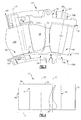
- Figure 4 illustrates a top view of the vane assembly 23.
- the first platform 34 and the second platform 36 are skewed relative to one another such that the mate faces 44, 46 of the first platform 34 are offset relative to the mate faces 44, 46 of the second platform 36. That is, a portion X of the first platform 34 circumferentially protrudes beyond the mate face 44 of the second platform 36.
- the stationary airfoil 38 is centered relative to a centerline axis 70 of the second platform 36 and is offset in a clockwise direction relative to a centerline axis 72 of the first platform 34.
- the centerline axis 70 and the centerline axis 72 are generally parallel to the engine's centerline axis A.
- An opposite configuration is also contemplated in which the stationary airfoil 38 is centered relative to the first platform 34 and is offset (or non-centered) relative to the centerline axis 70 of the second platform 36.
Applications Claiming Priority (1)
| Application Number | Priority Date | Filing Date | Title |
|---|---|---|---|
| US13/196,980 US9279335B2 (en) | 2011-08-03 | 2011-08-03 | Vane assembly for a gas turbine engine |
Publications (3)
| Publication Number | Publication Date |
|---|---|
| EP2554794A2 true EP2554794A2 (de) | 2013-02-06 |
| EP2554794A3 EP2554794A3 (de) | 2017-03-01 |
| EP2554794B1 EP2554794B1 (de) | 2019-11-20 |
Family
ID=47002545
Family Applications (1)
| Application Number | Title | Priority Date | Filing Date |
|---|---|---|---|
| EP12179027.3A Active EP2554794B1 (de) | 2011-08-03 | 2012-08-02 | Leitschaufelanordnung für ein gasturbinentriebwerk |
Country Status (2)
| Country | Link |
|---|---|
| US (1) | US9279335B2 (de) |
| EP (1) | EP2554794B1 (de) |
Cited By (2)
| Publication number | Priority date | Publication date | Assignee | Title |
|---|---|---|---|---|
| EP2960437A1 (de) | 2014-06-26 | 2015-12-30 | MTU Aero Engines GmbH | Leitschaufelvorrichtung für eine gasturbine sowie gasturbine mit einer solchen leitschaufelvorrichtung |
| WO2021173129A1 (en) * | 2020-02-26 | 2021-09-02 | Siemens Aktiengesellschaft | Gas turbine engine stationary vane with contoured platform |
Families Citing this family (4)
| Publication number | Priority date | Publication date | Assignee | Title |
|---|---|---|---|---|
| WO2014116259A1 (en) * | 2013-01-28 | 2014-07-31 | United Technologies Corporation | Multi-segment adjustable stator vane for a variable area vane arrangement |
| US11118471B2 (en) | 2013-11-18 | 2021-09-14 | Raytheon Technologies Corporation | Variable area vane endwall treatments |
| EP2949871B1 (de) * | 2014-05-07 | 2017-03-01 | United Technologies Corporation | Variables leitschaufelsegment |
| JP6385766B2 (ja) * | 2014-09-17 | 2018-09-05 | 株式会社東芝 | 車両用蓄電池装置 |
Family Cites Families (22)
| Publication number | Priority date | Publication date | Assignee | Title |
|---|---|---|---|---|
| US3075744A (en) | 1960-08-16 | 1963-01-29 | United Aircraft Corp | Turbine nozzle vane mounting means |
| US3224194A (en) | 1963-06-26 | 1965-12-21 | Curtiss Wright Corp | Gas turbine engine |
| US3910716A (en) | 1974-05-23 | 1975-10-07 | Westinghouse Electric Corp | Gas turbine inlet vane structure utilizing a stable ceramic spherical interface arrangement |
| US3966352A (en) | 1975-06-30 | 1976-06-29 | United Technologies Corporation | Variable area turbine |
| US4013377A (en) | 1975-10-08 | 1977-03-22 | Westinghouse Electric Corporation | Intermediate transition annulus for a two shaft gas turbine engine |
| US4688992A (en) | 1985-01-25 | 1987-08-25 | General Electric Company | Blade platform |
| US5222863A (en) | 1991-09-03 | 1993-06-29 | Jones Brian L | Turbine multisection hydrojet drive |
| DE4432999C2 (de) | 1994-09-16 | 1998-07-30 | Mtu Muenchen Gmbh | Laufrad einer Turbomaschine, insbesondere einer axial durchströmten Turbine eines Gasturbinentriebwerks |
| US5735673A (en) | 1996-12-04 | 1998-04-07 | United Technologies Corporation | Turbine engine rotor blade pair |
| US5931636A (en) | 1997-08-28 | 1999-08-03 | General Electric Company | Variable area turbine nozzle |
| CN100338337C (zh) * | 2002-06-07 | 2007-09-19 | 三菱重工业株式会社 | 汽轮机转子叶片组件及其组装方法 |
| GB0226690D0 (en) * | 2002-11-15 | 2002-12-24 | Rolls Royce Plc | Vane with modified base |
| US6843638B2 (en) | 2002-12-10 | 2005-01-18 | Honeywell International Inc. | Vane radial mounting apparatus |
| CH698087B1 (de) | 2004-09-08 | 2009-05-15 | Alstom Technology Ltd | Schaufel mit Deckbandelement. |
| GB0422507D0 (en) | 2004-10-11 | 2004-11-10 | Alstom Technology Ltd | Turbine blade and turbine rotor assembly |
| US7360990B2 (en) | 2004-10-13 | 2008-04-22 | General Electric Company | Methods and apparatus for assembling gas turbine engines |
| US7217081B2 (en) | 2004-10-15 | 2007-05-15 | Siemens Power Generation, Inc. | Cooling system for a seal for turbine vane shrouds |
| US7713022B2 (en) | 2007-03-06 | 2010-05-11 | United Technologies Operations | Small radial profile shroud for variable vane structure in a gas turbine engine |
| US8007229B2 (en) | 2007-05-24 | 2011-08-30 | United Technologies Corporation | Variable area turbine vane arrangement |
| US8202043B2 (en) * | 2007-10-15 | 2012-06-19 | United Technologies Corp. | Gas turbine engines and related systems involving variable vanes |
| US8240983B2 (en) | 2007-10-22 | 2012-08-14 | United Technologies Corp. | Gas turbine engine systems involving gear-driven variable vanes |
| US8206095B2 (en) | 2008-11-19 | 2012-06-26 | Alstom Technology Ltd | Compound variable elliptical airfoil fillet |
-
2011
- 2011-08-03 US US13/196,980 patent/US9279335B2/en active Active
-
2012
- 2012-08-02 EP EP12179027.3A patent/EP2554794B1/de active Active
Non-Patent Citations (1)
| Title |
|---|
| None |
Cited By (5)
| Publication number | Priority date | Publication date | Assignee | Title |
|---|---|---|---|---|
| EP2960437A1 (de) | 2014-06-26 | 2015-12-30 | MTU Aero Engines GmbH | Leitschaufelvorrichtung für eine gasturbine sowie gasturbine mit einer solchen leitschaufelvorrichtung |
| EP2960438A1 (de) | 2014-06-26 | 2015-12-30 | MTU Aero Engines GmbH | Leitschaufelvorrichtung für eine gasturbine sowie gasturbine mit einer solchen leitschaufelvorrichtung |
| US9982547B2 (en) | 2014-06-26 | 2018-05-29 | MTU Aero Engines AG | Guide mechanism for a gas turbine and gas turbine having such a guide mechanism |
| US10450877B2 (en) | 2014-06-26 | 2019-10-22 | MTU Aero Engines AG | Guide means for a gas turbine and gas turbine having such a guide means |
| WO2021173129A1 (en) * | 2020-02-26 | 2021-09-02 | Siemens Aktiengesellschaft | Gas turbine engine stationary vane with contoured platform |
Also Published As
| Publication number | Publication date |
|---|---|
| EP2554794A3 (de) | 2017-03-01 |
| EP2554794B1 (de) | 2019-11-20 |
| US9279335B2 (en) | 2016-03-08 |
| US20130034435A1 (en) | 2013-02-07 |
Similar Documents
| Publication | Publication Date | Title |
|---|---|---|
| EP2817490B1 (de) | Schaufelanordnung für einen gasturbinenmotor | |
| EP2554795B1 (de) | Leitschaufelanordnung für eine gasturbine | |
| CN107435561B (zh) | 用于冷却涡轮叶片的尖端叶冠的密封导轨的系统 | |
| EP2554794B1 (de) | Leitschaufelanordnung für ein gasturbinentriebwerk | |
| US20200024954A1 (en) | Integrated strut and igv configuration | |
| US9822647B2 (en) | High chord bucket with dual part span shrouds and curved dovetail | |
| EP2613000B1 (de) | System zur axialen Sicherung von Drehsegmenten einer Turbine und zugehöriges Verfahren | |
| US8439626B2 (en) | Turbine airfoil clocking | |
| EP2617944B1 (de) | Turbomaschinenschaufelspitzendeckbänder | |
| US20130170994A1 (en) | Device and method for aligning tip shrouds | |
| US20150345301A1 (en) | Rotor blade cooling flow | |
| US20170356298A1 (en) | Stator vane | |
| US20120156045A1 (en) | Methods, systems and apparatus relating to root and platform configurations for turbine rotor blades | |
| US9896946B2 (en) | Gas turbine engine rotor assembly and method of assembling the same | |
| US10480333B2 (en) | Turbine blade including balanced mateface condition | |
| US9284853B2 (en) | System and method for integrating sections of a turbine | |
| EP3828390A1 (de) | Turbomaschinendüse mit einem profil mit einer gekrümmten hinterkante | |
| EP2933437B1 (de) | Systeme und verfahren für verdrehsicherungsfunktionen | |
| EP2557268A2 (de) | System und Verfahren zur Kontrolle der Strömung in einer Strömungsmaschine | |
| US11639666B2 (en) | Stator with depressions in gaspath wall adjacent leading edges | |
| US20230073422A1 (en) | Stator with depressions in gaspath wall adjacent trailing edges | |
| US20170089210A1 (en) | Seal arrangement for compressor or turbine section of gas turbine engine | |
| US20170130596A1 (en) | System for integrating sections of a turbine |
Legal Events
| Date | Code | Title | Description |
|---|---|---|---|
| PUAI | Public reference made under article 153(3) epc to a published international application that has entered the european phase |
Free format text: ORIGINAL CODE: 0009012 |
|
| AK | Designated contracting states |
Kind code of ref document: A2 Designated state(s): AL AT BE BG CH CY CZ DE DK EE ES FI FR GB GR HR HU IE IS IT LI LT LU LV MC MK MT NL NO PL PT RO RS SE SI SK SM TR |
|
| AX | Request for extension of the european patent |
Extension state: BA ME |
|
| RAP1 | Party data changed (applicant data changed or rights of an application transferred) |
Owner name: UNITED TECHNOLOGIES CORPORATION |
|
| PUAL | Search report despatched |
Free format text: ORIGINAL CODE: 0009013 |
|
| AK | Designated contracting states |
Kind code of ref document: A3 Designated state(s): AL AT BE BG CH CY CZ DE DK EE ES FI FR GB GR HR HU IE IS IT LI LT LU LV MC MK MT NL NO PL PT RO RS SE SI SK SM TR |
|
| AX | Request for extension of the european patent |
Extension state: BA ME |
|
| RIC1 | Information provided on ipc code assigned before grant |
Ipc: F01D 9/04 20060101AFI20170124BHEP Ipc: F01D 17/16 20060101ALI20170124BHEP |
|
| STAA | Information on the status of an ep patent application or granted ep patent |
Free format text: STATUS: REQUEST FOR EXAMINATION WAS MADE |
|
| 17P | Request for examination filed |
Effective date: 20170901 |
|
| RBV | Designated contracting states (corrected) |
Designated state(s): AL AT BE BG CH CY CZ DE DK EE ES FI FR GB GR HR HU IE IS IT LI LT LU LV MC MK MT NL NO PL PT RO RS SE SI SK SM TR |
|
| STAA | Information on the status of an ep patent application or granted ep patent |
Free format text: STATUS: EXAMINATION IS IN PROGRESS |
|
| 17Q | First examination report despatched |
Effective date: 20180822 |
|
| GRAP | Despatch of communication of intention to grant a patent |
Free format text: ORIGINAL CODE: EPIDOSNIGR1 |
|
| STAA | Information on the status of an ep patent application or granted ep patent |
Free format text: STATUS: GRANT OF PATENT IS INTENDED |
|
| INTG | Intention to grant announced |
Effective date: 20190528 |
|
| GRAS | Grant fee paid |
Free format text: ORIGINAL CODE: EPIDOSNIGR3 |
|
| GRAA | (expected) grant |
Free format text: ORIGINAL CODE: 0009210 |
|
| STAA | Information on the status of an ep patent application or granted ep patent |
Free format text: STATUS: THE PATENT HAS BEEN GRANTED |
|
| AK | Designated contracting states |
Kind code of ref document: B1 Designated state(s): AL AT BE BG CH CY CZ DE DK EE ES FI FR GB GR HR HU IE IS IT LI LT LU LV MC MK MT NL NO PL PT RO RS SE SI SK SM TR |
|
| REG | Reference to a national code |
Ref country code: GB Ref legal event code: FG4D |
|
| REG | Reference to a national code |
Ref country code: CH Ref legal event code: EP |
|
| REG | Reference to a national code |
Ref country code: DE Ref legal event code: R096 Ref document number: 602012065770 Country of ref document: DE |
|
| REG | Reference to a national code |
Ref country code: IE Ref legal event code: FG4D |
|
| REG | Reference to a national code |
Ref country code: AT Ref legal event code: REF Ref document number: 1204429 Country of ref document: AT Kind code of ref document: T Effective date: 20191215 |
|
| REG | Reference to a national code |
Ref country code: NL Ref legal event code: MP Effective date: 20191120 |
|
| REG | Reference to a national code |
Ref country code: LT Ref legal event code: MG4D |
|
| PG25 | Lapsed in a contracting state [announced via postgrant information from national office to epo] |
Ref country code: ES Free format text: LAPSE BECAUSE OF FAILURE TO SUBMIT A TRANSLATION OF THE DESCRIPTION OR TO PAY THE FEE WITHIN THE PRESCRIBED TIME-LIMIT Effective date: 20191120 Ref country code: FI Free format text: LAPSE BECAUSE OF FAILURE TO SUBMIT A TRANSLATION OF THE DESCRIPTION OR TO PAY THE FEE WITHIN THE PRESCRIBED TIME-LIMIT Effective date: 20191120 Ref country code: SE Free format text: LAPSE BECAUSE OF FAILURE TO SUBMIT A TRANSLATION OF THE DESCRIPTION OR TO PAY THE FEE WITHIN THE PRESCRIBED TIME-LIMIT Effective date: 20191120 Ref country code: LV Free format text: LAPSE BECAUSE OF FAILURE TO SUBMIT A TRANSLATION OF THE DESCRIPTION OR TO PAY THE FEE WITHIN THE PRESCRIBED TIME-LIMIT Effective date: 20191120 Ref country code: LT Free format text: LAPSE BECAUSE OF FAILURE TO SUBMIT A TRANSLATION OF THE DESCRIPTION OR TO PAY THE FEE WITHIN THE PRESCRIBED TIME-LIMIT Effective date: 20191120 Ref country code: GR Free format text: LAPSE BECAUSE OF FAILURE TO SUBMIT A TRANSLATION OF THE DESCRIPTION OR TO PAY THE FEE WITHIN THE PRESCRIBED TIME-LIMIT Effective date: 20200221 Ref country code: NO Free format text: LAPSE BECAUSE OF FAILURE TO SUBMIT A TRANSLATION OF THE DESCRIPTION OR TO PAY THE FEE WITHIN THE PRESCRIBED TIME-LIMIT Effective date: 20200220 Ref country code: BG Free format text: LAPSE BECAUSE OF FAILURE TO SUBMIT A TRANSLATION OF THE DESCRIPTION OR TO PAY THE FEE WITHIN THE PRESCRIBED TIME-LIMIT Effective date: 20200220 Ref country code: NL Free format text: LAPSE BECAUSE OF FAILURE TO SUBMIT A TRANSLATION OF THE DESCRIPTION OR TO PAY THE FEE WITHIN THE PRESCRIBED TIME-LIMIT Effective date: 20191120 |
|
| PG25 | Lapsed in a contracting state [announced via postgrant information from national office to epo] |
Ref country code: IS Free format text: LAPSE BECAUSE OF FAILURE TO SUBMIT A TRANSLATION OF THE DESCRIPTION OR TO PAY THE FEE WITHIN THE PRESCRIBED TIME-LIMIT Effective date: 20200320 Ref country code: HR Free format text: LAPSE BECAUSE OF FAILURE TO SUBMIT A TRANSLATION OF THE DESCRIPTION OR TO PAY THE FEE WITHIN THE PRESCRIBED TIME-LIMIT Effective date: 20191120 Ref country code: RS Free format text: LAPSE BECAUSE OF FAILURE TO SUBMIT A TRANSLATION OF THE DESCRIPTION OR TO PAY THE FEE WITHIN THE PRESCRIBED TIME-LIMIT Effective date: 20191120 |
|
| PG25 | Lapsed in a contracting state [announced via postgrant information from national office to epo] |
Ref country code: AL Free format text: LAPSE BECAUSE OF FAILURE TO SUBMIT A TRANSLATION OF THE DESCRIPTION OR TO PAY THE FEE WITHIN THE PRESCRIBED TIME-LIMIT Effective date: 20191120 |
|
| PG25 | Lapsed in a contracting state [announced via postgrant information from national office to epo] |
Ref country code: RO Free format text: LAPSE BECAUSE OF FAILURE TO SUBMIT A TRANSLATION OF THE DESCRIPTION OR TO PAY THE FEE WITHIN THE PRESCRIBED TIME-LIMIT Effective date: 20191120 Ref country code: DK Free format text: LAPSE BECAUSE OF FAILURE TO SUBMIT A TRANSLATION OF THE DESCRIPTION OR TO PAY THE FEE WITHIN THE PRESCRIBED TIME-LIMIT Effective date: 20191120 Ref country code: EE Free format text: LAPSE BECAUSE OF FAILURE TO SUBMIT A TRANSLATION OF THE DESCRIPTION OR TO PAY THE FEE WITHIN THE PRESCRIBED TIME-LIMIT Effective date: 20191120 Ref country code: PT Free format text: LAPSE BECAUSE OF FAILURE TO SUBMIT A TRANSLATION OF THE DESCRIPTION OR TO PAY THE FEE WITHIN THE PRESCRIBED TIME-LIMIT Effective date: 20200412 Ref country code: CZ Free format text: LAPSE BECAUSE OF FAILURE TO SUBMIT A TRANSLATION OF THE DESCRIPTION OR TO PAY THE FEE WITHIN THE PRESCRIBED TIME-LIMIT Effective date: 20191120 |
|
| REG | Reference to a national code |
Ref country code: AT Ref legal event code: MK05 Ref document number: 1204429 Country of ref document: AT Kind code of ref document: T Effective date: 20191120 |
|
| REG | Reference to a national code |
Ref country code: DE Ref legal event code: R097 Ref document number: 602012065770 Country of ref document: DE |
|
| PG25 | Lapsed in a contracting state [announced via postgrant information from national office to epo] |
Ref country code: SM Free format text: LAPSE BECAUSE OF FAILURE TO SUBMIT A TRANSLATION OF THE DESCRIPTION OR TO PAY THE FEE WITHIN THE PRESCRIBED TIME-LIMIT Effective date: 20191120 Ref country code: SK Free format text: LAPSE BECAUSE OF FAILURE TO SUBMIT A TRANSLATION OF THE DESCRIPTION OR TO PAY THE FEE WITHIN THE PRESCRIBED TIME-LIMIT Effective date: 20191120 |
|
| PLBE | No opposition filed within time limit |
Free format text: ORIGINAL CODE: 0009261 |
|
| STAA | Information on the status of an ep patent application or granted ep patent |
Free format text: STATUS: NO OPPOSITION FILED WITHIN TIME LIMIT |
|
| 26N | No opposition filed |
Effective date: 20200821 |
|
| PG25 | Lapsed in a contracting state [announced via postgrant information from national office to epo] |
Ref country code: AT Free format text: LAPSE BECAUSE OF FAILURE TO SUBMIT A TRANSLATION OF THE DESCRIPTION OR TO PAY THE FEE WITHIN THE PRESCRIBED TIME-LIMIT Effective date: 20191120 Ref country code: PL Free format text: LAPSE BECAUSE OF FAILURE TO SUBMIT A TRANSLATION OF THE DESCRIPTION OR TO PAY THE FEE WITHIN THE PRESCRIBED TIME-LIMIT Effective date: 20191120 Ref country code: SI Free format text: LAPSE BECAUSE OF FAILURE TO SUBMIT A TRANSLATION OF THE DESCRIPTION OR TO PAY THE FEE WITHIN THE PRESCRIBED TIME-LIMIT Effective date: 20191120 |
|
| PG25 | Lapsed in a contracting state [announced via postgrant information from national office to epo] |
Ref country code: IT Free format text: LAPSE BECAUSE OF FAILURE TO SUBMIT A TRANSLATION OF THE DESCRIPTION OR TO PAY THE FEE WITHIN THE PRESCRIBED TIME-LIMIT Effective date: 20191120 |
|
| PG25 | Lapsed in a contracting state [announced via postgrant information from national office to epo] |
Ref country code: MC Free format text: LAPSE BECAUSE OF FAILURE TO SUBMIT A TRANSLATION OF THE DESCRIPTION OR TO PAY THE FEE WITHIN THE PRESCRIBED TIME-LIMIT Effective date: 20191120 |
|
| REG | Reference to a national code |
Ref country code: CH Ref legal event code: PL |
|
| PG25 | Lapsed in a contracting state [announced via postgrant information from national office to epo] |
Ref country code: LI Free format text: LAPSE BECAUSE OF NON-PAYMENT OF DUE FEES Effective date: 20200831 Ref country code: CH Free format text: LAPSE BECAUSE OF NON-PAYMENT OF DUE FEES Effective date: 20200831 Ref country code: LU Free format text: LAPSE BECAUSE OF NON-PAYMENT OF DUE FEES Effective date: 20200802 |
|
| REG | Reference to a national code |
Ref country code: BE Ref legal event code: MM Effective date: 20200831 |
|
| PG25 | Lapsed in a contracting state [announced via postgrant information from national office to epo] |
Ref country code: BE Free format text: LAPSE BECAUSE OF NON-PAYMENT OF DUE FEES Effective date: 20200831 Ref country code: IE Free format text: LAPSE BECAUSE OF NON-PAYMENT OF DUE FEES Effective date: 20200802 |
|
| PG25 | Lapsed in a contracting state [announced via postgrant information from national office to epo] |
Ref country code: TR Free format text: LAPSE BECAUSE OF FAILURE TO SUBMIT A TRANSLATION OF THE DESCRIPTION OR TO PAY THE FEE WITHIN THE PRESCRIBED TIME-LIMIT Effective date: 20191120 Ref country code: MT Free format text: LAPSE BECAUSE OF FAILURE TO SUBMIT A TRANSLATION OF THE DESCRIPTION OR TO PAY THE FEE WITHIN THE PRESCRIBED TIME-LIMIT Effective date: 20191120 Ref country code: CY Free format text: LAPSE BECAUSE OF FAILURE TO SUBMIT A TRANSLATION OF THE DESCRIPTION OR TO PAY THE FEE WITHIN THE PRESCRIBED TIME-LIMIT Effective date: 20191120 |
|
| PG25 | Lapsed in a contracting state [announced via postgrant information from national office to epo] |
Ref country code: MK Free format text: LAPSE BECAUSE OF FAILURE TO SUBMIT A TRANSLATION OF THE DESCRIPTION OR TO PAY THE FEE WITHIN THE PRESCRIBED TIME-LIMIT Effective date: 20191120 |
|
| REG | Reference to a national code |
Ref country code: DE Ref legal event code: R081 Ref document number: 602012065770 Country of ref document: DE Owner name: RAYTHEON TECHNOLOGIES CORPORATION (N.D.GES.D.S, US Free format text: FORMER OWNER: UNITED TECHNOLOGIES CORPORATION, FARMINGTON, CONN., US |
|
| P01 | Opt-out of the competence of the unified patent court (upc) registered |
Effective date: 20230520 |
|
| PGFP | Annual fee paid to national office [announced via postgrant information from national office to epo] |
Ref country code: GB Payment date: 20230720 Year of fee payment: 12 |
|
| PGFP | Annual fee paid to national office [announced via postgrant information from national office to epo] |
Ref country code: FR Payment date: 20230720 Year of fee payment: 12 Ref country code: DE Payment date: 20230720 Year of fee payment: 12 |