EP2554792A1 - Doppeldüsen-filmkühlungsstruktur - Google Patents
Doppeldüsen-filmkühlungsstruktur Download PDFInfo
- Publication number
- EP2554792A1 EP2554792A1 EP11758943A EP11758943A EP2554792A1 EP 2554792 A1 EP2554792 A1 EP 2554792A1 EP 11758943 A EP11758943 A EP 11758943A EP 11758943 A EP11758943 A EP 11758943A EP 2554792 A1 EP2554792 A1 EP 2554792A1
- Authority
- EP
- European Patent Office
- Prior art keywords
- cooling medium
- wall surface
- injection
- injection holes
- pair
- Prior art date
- Legal status (The legal status is an assumption and is not a legal conclusion. Google has not performed a legal analysis and makes no representation as to the accuracy of the status listed.)
- Granted
Links
Images


Classifications
-
- F—MECHANICAL ENGINEERING; LIGHTING; HEATING; WEAPONS; BLASTING
- F28—HEAT EXCHANGE IN GENERAL
- F28F—DETAILS OF HEAT-EXCHANGE AND HEAT-TRANSFER APPARATUS, OF GENERAL APPLICATION
- F28F3/00—Plate-like or laminated elements; Assemblies of plate-like or laminated elements
- F28F3/12—Elements constructed in the shape of a hollow panel, e.g. with channels
-
- F—MECHANICAL ENGINEERING; LIGHTING; HEATING; WEAPONS; BLASTING
- F01—MACHINES OR ENGINES IN GENERAL; ENGINE PLANTS IN GENERAL; STEAM ENGINES
- F01D—NON-POSITIVE DISPLACEMENT MACHINES OR ENGINES, e.g. STEAM TURBINES
- F01D5/00—Blades; Blade-carrying members; Heating, heat-insulating, cooling or antivibration means on the blades or the members
- F01D5/12—Blades
- F01D5/14—Form or construction
- F01D5/18—Hollow blades, i.e. blades with cooling or heating channels or cavities; Heating, heat-insulating or cooling means on blades
- F01D5/186—Film cooling
-
- F—MECHANICAL ENGINEERING; LIGHTING; HEATING; WEAPONS; BLASTING
- F23—COMBUSTION APPARATUS; COMBUSTION PROCESSES
- F23R—GENERATING COMBUSTION PRODUCTS OF HIGH PRESSURE OR HIGH VELOCITY, e.g. GAS-TURBINE COMBUSTION CHAMBERS
- F23R3/00—Continuous combustion chambers using liquid or gaseous fuel
- F23R3/02—Continuous combustion chambers using liquid or gaseous fuel characterised by the air-flow or gas-flow configuration
- F23R3/04—Air inlet arrangements
- F23R3/06—Arrangement of apertures along the flame tube
-
- F—MECHANICAL ENGINEERING; LIGHTING; HEATING; WEAPONS; BLASTING
- F05—INDEXING SCHEMES RELATING TO ENGINES OR PUMPS IN VARIOUS SUBCLASSES OF CLASSES F01-F04
- F05D—INDEXING SCHEME FOR ASPECTS RELATING TO NON-POSITIVE-DISPLACEMENT MACHINES OR ENGINES, GAS-TURBINES OR JET-PROPULSION PLANTS
- F05D2250/00—Geometry
- F05D2250/10—Two-dimensional
- F05D2250/14—Two-dimensional elliptical
-
- F—MECHANICAL ENGINEERING; LIGHTING; HEATING; WEAPONS; BLASTING
- F05—INDEXING SCHEMES RELATING TO ENGINES OR PUMPS IN VARIOUS SUBCLASSES OF CLASSES F01-F04
- F05D—INDEXING SCHEME FOR ASPECTS RELATING TO NON-POSITIVE-DISPLACEMENT MACHINES OR ENGINES, GAS-TURBINES OR JET-PROPULSION PLANTS
- F05D2250/00—Geometry
- F05D2250/70—Shape
- F05D2250/72—Shape symmetric
-
- F—MECHANICAL ENGINEERING; LIGHTING; HEATING; WEAPONS; BLASTING
- F05—INDEXING SCHEMES RELATING TO ENGINES OR PUMPS IN VARIOUS SUBCLASSES OF CLASSES F01-F04
- F05D—INDEXING SCHEME FOR ASPECTS RELATING TO NON-POSITIVE-DISPLACEMENT MACHINES OR ENGINES, GAS-TURBINES OR JET-PROPULSION PLANTS
- F05D2260/00—Function
- F05D2260/20—Heat transfer, e.g. cooling
- F05D2260/202—Heat transfer, e.g. cooling by film cooling
-
- Y—GENERAL TAGGING OF NEW TECHNOLOGICAL DEVELOPMENTS; GENERAL TAGGING OF CROSS-SECTIONAL TECHNOLOGIES SPANNING OVER SEVERAL SECTIONS OF THE IPC; TECHNICAL SUBJECTS COVERED BY FORMER USPC CROSS-REFERENCE ART COLLECTIONS [XRACs] AND DIGESTS
- Y02—TECHNOLOGIES OR APPLICATIONS FOR MITIGATION OR ADAPTATION AGAINST CLIMATE CHANGE
- Y02T—CLIMATE CHANGE MITIGATION TECHNOLOGIES RELATED TO TRANSPORTATION
- Y02T50/00—Aeronautics or air transport
- Y02T50/60—Efficient propulsion technologies, e.g. for aircraft
Definitions
- the present invention relates to a film cooling structure in which injection holes are provided on a wall surface facing a high-temperature gas passage, such as a rotor blade, a stator vane, and an inner tube of a combustor, in a gas turbine engine, and cooling of the wall surface is performed by flowing a cooling medium injected from the injection holes along the wall surface.
- a high-temperature gas passage such as a rotor blade, a stator vane, and an inner tube of a combustor
- injection holes are provided on a wall surface such as a rotor blade in a gas turbine engine (hereinafter simply referred to as "gas turbine") such that they are oriented in the same direction.
- a film flow of a cooling medium such as air injected from these injection holes cools the wall surface exposed to high-temperature gas.
- a rib having a substantially isosceles triangle shape in a plan view having a base at a rear end of each of the injections holes and a vertex positioned at an upstream side (front side), is provided at a center portion of an injection port through which the cooling medium is injected to the wall surface, and is configured to disperse the cooling medium to the right and to the left, thereby cooling the wall surface uniformly (Patent Literature 1).
- Patent Literature 1 Japanese Laid-Open Patent Application Publication No. 2008-248733
- the rib extends to the rear end of the injection hole and the both side surfaces of the rib extending in a flow direction of the cooling medium have inclined surfaces inclined toward the center of cooling medium flows from inward of the wall surface to the wall surface. Therefore, the rib cannot separate the cooling medium flows from each other sufficiently. That is, the cooling medium is separated by the rib into a pair of rightward and leftward flows. At this time, a part of the cooling medium is guided, along the inclined side surfaces of the rib, toward a center axis between the pair of cooling medium flows from a front end to a rear end of the rib, i.e., over a wide region to the rear end of the injection hole.
- a part of the cooling medium is injected in an obliquely rearward direction from the rear end of the injection hole toward the center, which causes the cooling medium flows to be separated insufficiently.
- a part of the cooling medium flows into a low-pressure portion between the cooling medium flows.
- a pressure in the low-pressure portion increases, and the cooling medium flows are separated easily from the wall surface.
- a film efficiency indicating a cooling efficiency on the wall surface decreases.
- Tg is a temperature of gas
- Tf is a surface temperature of the wall surface
- Tc is a temperature of the cooling medium on the wall surface.
- an object of the present invention is to provide a film cooling structure which is capable of suppressing a cooling medium film from being separated from a wall surface such as a rotor blade or a stator vane in a gas turbine, to increase a film efficiency on the wall surface, thereby capable of cooling the wall surface efficiently.
- a double-jet type film cooling structure of the present invention comprises one or more pairs of injection holes which are provided on a wall surface facing a high-temperature gas passage and inject a cooling medium to the passage; a single supply passage provided inside a wall to supply the cooling medium to the each pair of injection holes; and a separating section provided between the injection holes forming the each pair in a location forward relative to rear ends of the injection holes to separate the cooling medium supplied from the supply passage into components flowing to the injection holes forming the each pair, respectively; wherein an injection direction of the cooling medium is set to be inclined with respect to a flow direction of the high-temperature gas so that the components of the cooling medium injected from the injection holes forming the each pair form swirl flows oriented in directions to push the components of the cooling medium against the wall surface.
- the cooling medium which has passed through the single supply passage is separated by the separating section into the components flowing to the pair of injection holes, respectively. Since the separating section is positioned forward relative to the rear ends of the injection holes, the separated components of the cooling medium are restricted by the rear portions of the injection holes and form a pair of straight flows having high directivities. A low-pressure portion having a sufficiently low pressure is generated between the pair of straight flows having high directivities. Therefore, the swirl flows formed by the straight flows cause formation of forceful flows inwardly swirled from areas surrounding the straight flows to the low-pressure portion and oriented toward the wall surface. Because of this, the cooling medium is suppressed from being separated from the wall surface and a film efficiency on the wall surface is increased, which makes it possible to cool the wall surface effectively.
- the separating section is preferably inclined in a rearward direction around an axis orthogonal to a direction in which the cooling medium colliding against the separating section travels, with respect to a virtual orthogonal plane orthogonal to the direction in which the cooling medium travels.
- the cooling medium colliding against the separating section is separated evenly into the components along the directions of the injection holes. Since the separating section has no inclined side surface, portions of the separated pair of components of the cooling medium are suppressed from flowing to a center portion along the direction in which the cooling medium travels, and the components of the cooling medium are separated from each other sufficiently. As a result, the low-pressure portion is formed surely between the straight flows of the cooling medium, and the swirl flows push the cooling medium flows forcefully against the wall surface.
- horizontal injection angles formed between the injection directions of the components of the cooling medium injected from the injection holes forming the each pair, the injection directions being along the wall surface, and the flow direction of the high-temperature gas are set to angles of ⁇ 1 which are oriented in opposite directions with respect to the flow direction of the high-temperature gas.
- each of the horizontal injection angles ⁇ 1 is preferably in a range of 5 to 85 degrees.
- a vertical injection angle ⁇ 2 which is formed between the wall surface and the injection direction of the component of the cooling medium injected from each of the injection holes to the high-temperature gas passage is in a range of 5 to 85 degrees.
- the injection holes forming each pair in an opening facing the wall surface, except for the separating section have substantially oval shapes having long axes along the injection directions, respectively; and a distance between centers of the oval shapes is set to 0 to 2D when a hole diameter of the supply passage is D.
- a length L1 of the supply passage is set to 0 to 10D when a hole diameter of the supply passage is D.
- a distance L2 from an exit of the supply passage to the opening of the pair of injection holes, the opening facing the wall surface is set to 0.5D to 6D when a hole diameter of the supply passage is D.
- forceful swirl flows oriented toward the wall surface are formed, which makes it possible to cool the wall surface more effectively.
- a favorable film flow can be formed on a wall surface exposed to high-temperature gas while suppressing a cooling medium from being separated from the wall surface, and thus, efficient cooling of the wall surface can be carried out.
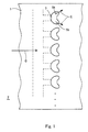
- Fig. 1 is a plan view showing a wall surface 1 which uses a double-jet type film cooling structure according to an embodiment of the present invention.
- the wall surface 1 is exposed to high-temperature gas G flowing in an arrow direction.
- a plurality of injection openings 3 through which a cooling medium such as air is injected to a passage 2 of the high-temperature gas G are aligned in a direction (upward and downward direction in Fig. 1 ) which is substantially orthogonal to the flow direction of the high-temperature gas G.
- a cooling medium such as air
- Each of the injection openings 3 includes a pair of first and second injection holes 5a, 5b arranged in the upward and downward direction.
- Each pair of the injection holes 5a, 5b are circular holes formed on the wall surface 1 from an oblique direction by a drill or the like.
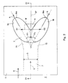
- the injection holes 5a, 5b forming each pair are opened in an oval shape on the wall surface 1, as will be described in detail later. As shown in an enlarged front view of Fig.
- the injection holes 5a, 5b forming each pair are formed such that injection directions A, B of a cooling medium C injected from the injection holes 5a, 5b are oriented in different directions (having different directivities) on a plane along the wall surface 1, i.e., in a plan view when viewed from the direction orthogonal to the wall surface 1.
- the components of the cooling medium C are injected in directions apart from each other.
- a single supply passage 7 is formed to supply the cooling medium C to the injection holes 5a, 5b forming each pair.
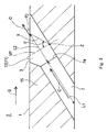
- the supply passage 7 has a circular cross-section, and extends from the injection opening 3 such that it is inclined in a forward direction (toward upstream side), inside the wall of the wall surface 1.
- Two branch passages 71, 72 each having a circular cross-section branch from the rear end of the supply passage 7, and openings of the branch passages 71, 72 on the wall surface 1 are the injection holes 5a, 5b, respectively.
- the injection holes 5a, 5b forming each pair are symmetric with respect to a virtual flat plane IP passing through between the injection holes 5a, 5b, being parallel to a direction in which the high-temperature gas G travels and being orthogonal to the wall surface 1.
- a separating section 9 is provided in a location forward relative to a rear end 5aa of the injection hole 5a and a rear end 5bb of the injection hole 5b.
- the supply passage 7 is a straight passage, and its passage center line is positioned on the virtual flat plane IP.
- the separating section 9 is positioned on the direction in which the cooling medium C supplied from the supply passage 7 travels, and is formed as a flat wall surface against which a part of the cooling medium C collides and which has no bent portion.
- the separating section 9 is inclined with an inclination angle ⁇ in a rearward direction around an axis Z orthogonal to the direction in which the cooling medium C from the supply passage 7 travels, with respect to a virtual orthogonal plane VP orthogonal to the direction in which the cooling medium C travels.
- the cooling medium C passes through the supply passage 7, and then its components C1, C2 flowing in regions closer to both peripheral portions flow into the injection holes 5a, 5b separated by the separating section 9 and are injected to the high-temperature passage 2 as straight cooling medium flows F1, F2 oriented in directions in which the injection holes 5a, 5b extend, respectively.
- the straight cooling medium flows F1, F2 injected from portions of the injections holes 5a, 5b which are located rearward relative to the separating section 9 are formed as flows having high directivities.
- the separated flow F3 flows out from the separating section 9.
- the separated flow F3 flows between the straight cooling medium flows F1, F2 and serves to separate the straight cooling medium flows F1, F2 from each other.
- the mixed flow F4 is joined to the straight cooling medium flow F1, while the mixed flow F5 is joined to the straight cooling medium flow F2.
- Fig. 6 shows the cross-section of the high-temperature gas passage 2, which is orthogonal to the flow direction of the high-temperature gas G.
- the separated flow F3 from the separating section 9 allows the straight cooling medium flows F1, F2 having high directivities to be separated from each other, in the direction parallel to the wall surface 1, thereby resulting in a forceful low-pressure portion 11 between the straight cooling medium flows F1, F2.
- swirl flows S1, S2 oriented in opposite directions are generated in the straight cooling medium flows F1, F2 such that the swirl flows S1, S2 inwardly swirl the cooling medium C toward the wall surface 1, in a portion between the straight cooling medium flows F1, F2.
- the swirl flows S1, S2 act to push the straight cooling medium flows F1, F2, respectively, against the wall surface 1.
- the swirl flows S1, S2 are formed to push the cooling medium C, against the wall surface 1.
- the injections holes 5a, 5b forming each pair in the injection openings 3 facing the wall surface 1, except for the separating section 9, have substantially oval shapes having long axes along the injection directions A, B, respectively.
- the injections holes 5a, 5b are disposed such that a distance W between a center O1 of the oval shape of the injection hole 5a and a center O2 of the oval shape of the injection hole 5b is preferably in a range of 0D ⁇ 2D, more preferably in a range of 0.5D - 1.5D, when a hole diameter of the supply passage 7 is D.
- the distance W between the center O1 and the center O2 may be 0D (i.e., the center O1 and the center O2 conform to each other).
- the injection opening 3 has a shape in which the oval shapes of the injection holes 5a, 5b partially overlap with each other.
- the distance W between the center O1 and the center O2 is set to 1.3D.
- a horizontal injection angle ⁇ 1 formed between a component in the injection direction of the cooling medium C injected from each of the injection holes 5a, 5b forming each pair to the high-temperature gas passage 2, which component is parallel to the wall surface 1, i.e., the long axis of the oval shape of each of the injection holes 5a, 5b, when viewed from the direction orthogonal to the wall surface 1, and the flow direction of the high-temperature gas G is, preferably, in a range of 5 to 85 degrees, more preferably in a range of 25 to 35 degrees.
- the horizontal injection angle ⁇ 1 is set to about 30 degrees.
- the horizontal injection angle ⁇ 1 is set to about 30 degrees.
- a vertical injection angle ⁇ 2 formed between the wall surface 1 and the injection direction of the cooling medium C injected from each of the injection holes 5a, 5b forming each pair to the high-temperature gas passage 2 is, preferably, in a range of 5 to 85 degrees, more preferably in a range of 20 to 40 degrees.
- the vertical injection angle ⁇ 2 is set to about 30 degrees.
- L1 : L2 3 : 2.
- the supply passage length L1 is preferably in a range of 0D ⁇ 10D, more preferably in a range of 1D ⁇ 5D, in the relation with a hole diameter of D of the supply passage 7.
- the supply passage length L1 is 0D means that the supply passage 7 exists but its length L1 is very small.
- the distance L2 between the supply passage and the injection opening is preferably in a range of 0.5D ⁇ 6D, more preferably in a range of 1D - 4D. If the length L1 and the distance L2 fall outside the above ranges, the straight cooling medium flows F1, F2 will not flow straight in a sufficient level, which will not result in the swirl flows S1, S2 having a desired force.
- the supply passage length L1 is the length along the center axis of the supply passage 7, and the distance L2 between the supply passage and the injection opening is the distance along the center axis of the supply passage 7.
- the supply passage length L1 is set to 3D, and the distance L2 between the supply passage and the injection opening is set to 2D. According to an experiment, when the supply passage length L1 was set to 3D, and the distance L2 between the supply passage and the injection opening was set to 2D, a film efficiency became twice to three times higher than that of the conventional structure.
- the inclination angle ⁇ of the separating section 9 with respect to the virtual orthogonal plane VP is preferably in a range of 30 to 85 degrees and more preferably in a range of 60 to 80 degrees. In the present embodiment, the inclination angle ⁇ is set to 70 degrees.
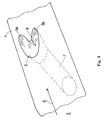
- Fig. 6 is an isogram diagram of the film efficiency ⁇ f,ad obtained on the wall surface 1 by forming the injection holes 5a, 5b of Fig. 2 .
- the cooling medium C injected from each of the injection holes 5a, 5b forms a region of a film efficiency of 1.0 in its downstream region, a region of a film efficiency of 0.8 which surrounds the region of a film efficiency of 1.0, and a region of a film efficiency of 0.6 which surrounds the region of a film efficiency of 0.8, each of the regions having a wider range.
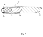
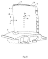
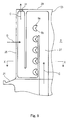
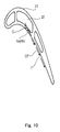
- Figs. 8 to 10 show examples in which the present invention is applied to a turbine blade of a gas turbine.
- the gas turbine includes a compressor for compressing air, a combustor which is supplied with a fuel and the compressed air supplied from the compressor and combusts the fuel, and a turbine actuated by high-temperature and high-pressure combustion gas from the combustor.
- the turbine is configured in such a manner that many rotor blades 23 are implanted in the outer peripheral portion of a turbine disc 21 of Fig. 9 . In a portion of the blade surface (wall surface 1) the rotor blade 23 of Fig.
- a cooling medium passage 27 having a folded shape as shown in Fig. 9 is formed inside of the rotor blade 23 .
- the injection holes 5a, 5b communicate with an intermediate portion of the cooling medium passage 27.
- the cooling medium C which has been extracted from the compressor and comprise air, is introduced into the cooling medium passage 27 through a passage inside of the turbine disc 21 and injected from the injection holes 5a, 5b. After that, the cooling medium C is injected into the passage 2 through an injection hole 31 which is opened in a blade tip 29.
- the cooling medium C injected from the injection holes 5a, 5b which are opened in the blade surface of Fig. 10 which is the wall surface 1 forms a film flow CF of the cooling medium C on the blade surface 1, which cools the rotor blade 23 effectively.
- plural pairs of injection holes 5a, 5b are aligned at equal intervals in the upward and downward direction
- the number and arrangement of the plural pairs of injection holes 5a, 5b may be suitably selected.
- the present invention is widely applicable to the wall surface facing the high-temperature gas passage such as a stator vane, and an inner tube of a combustor, as well as the rotor blade of the gas turbine.
- the present invention is useful in suppressing a cooling medium from being separated from a wall surface and effectively cooling the wall surface, in a film cooling structure in which injection holes are provided on the wall surface facing a high-temperature gas passage such as a rotor blade, a stator vane and an inner tube of a combustor in a gas turbine engine, and cooling of the wall surface is performed by flowing a cooling medium injected from the injection holes along the wall surface.
- a high-temperature gas passage such as a rotor blade, a stator vane and an inner tube of a combustor in a gas turbine engine
- the present invention is widely applicable to the wall surface facing the high-temperature gas passage such as the stator vane, and the inner tube of the combustor, as well as the rotor blade of the gas turbine.
Landscapes
- Engineering & Computer Science (AREA)
- Mechanical Engineering (AREA)
- General Engineering & Computer Science (AREA)
- Chemical & Material Sciences (AREA)
- Combustion & Propulsion (AREA)
- Physics & Mathematics (AREA)
- Thermal Sciences (AREA)
- Turbine Rotor Nozzle Sealing (AREA)
Applications Claiming Priority (2)
| Application Number | Priority Date | Filing Date | Title |
|---|---|---|---|
| JP2010067329A JP4954309B2 (ja) | 2010-03-24 | 2010-03-24 | ダブルジェット式フィルム冷却構造 |
| PCT/JP2011/001207 WO2011118131A1 (ja) | 2010-03-24 | 2011-03-02 | ダブルジェット式フィルム冷却構造 |
Publications (3)
| Publication Number | Publication Date |
|---|---|
| EP2554792A1 true EP2554792A1 (de) | 2013-02-06 |
| EP2554792A4 EP2554792A4 (de) | 2013-09-04 |
| EP2554792B1 EP2554792B1 (de) | 2020-10-07 |
Family
ID=44672712
Family Applications (1)
| Application Number | Title | Priority Date | Filing Date |
|---|---|---|---|
| EP11758943.2A Active EP2554792B1 (de) | 2010-03-24 | 2011-03-02 | Doppeldüsen-filmkühlungsstruktur |
Country Status (4)
| Country | Link |
|---|---|
| US (1) | US9599411B2 (de) |
| EP (1) | EP2554792B1 (de) |
| JP (1) | JP4954309B2 (de) |
| WO (1) | WO2011118131A1 (de) |
Cited By (7)
| Publication number | Priority date | Publication date | Assignee | Title |
|---|---|---|---|---|
| CN103437889A (zh) * | 2013-08-06 | 2013-12-11 | 清华大学 | 一种用于燃气涡轮发动机冷却的分支气膜孔结构 |
| EP2799775A3 (de) * | 2013-05-01 | 2015-04-08 | General Electric Company | Substrat mit geformten Kühllöchern und Herstellungsverfahren |
| CN104879171A (zh) * | 2015-05-08 | 2015-09-02 | 西北工业大学 | 一种用于涡轮叶片的y型气膜孔结构 |
| CN105308267A (zh) * | 2013-05-22 | 2016-02-03 | 川崎重工业株式会社 | 双射流式气膜冷却构造及其制造方法 |
| CN105298649A (zh) * | 2015-11-20 | 2016-02-03 | 清华大学 | 一种用于燃气涡轮发动机薄壁热端部件的气膜冷却孔结构 |
| US9696035B2 (en) | 2010-10-29 | 2017-07-04 | General Electric Company | Method of forming a cooling hole by laser drilling |
| EP3450682A1 (de) * | 2017-08-30 | 2019-03-06 | Siemens Aktiengesellschaft | Wand eines bauteils für heissgas und zugehöriges bauteil |
Families Citing this family (37)
| Publication number | Priority date | Publication date | Assignee | Title |
|---|---|---|---|---|
| JP2013100771A (ja) * | 2011-11-08 | 2013-05-23 | Central Research Institute Of Electric Power Industry | 高温部品のフィルム冷却構造 |
| JP5923936B2 (ja) * | 2011-11-09 | 2016-05-25 | 株式会社Ihi | フィルム冷却構造及びタービン翼 |
| JP6019578B2 (ja) | 2011-12-15 | 2016-11-02 | 株式会社Ihi | タービン翼 |
| JP5982807B2 (ja) * | 2011-12-15 | 2016-08-31 | 株式会社Ihi | タービン翼 |
| CN103244196B (zh) * | 2012-02-08 | 2015-04-22 | 中国科学院工程热物理研究所 | 一种离散气膜冷却孔型 |
| US8689568B2 (en) * | 2012-02-15 | 2014-04-08 | United Technologies Corporation | Cooling hole with thermo-mechanical fatigue resistance |
| US9416971B2 (en) * | 2012-02-15 | 2016-08-16 | United Technologies Corporation | Multiple diffusing cooling hole |
| US9422815B2 (en) | 2012-02-15 | 2016-08-23 | United Technologies Corporation | Gas turbine engine component with compound cusp cooling configuration |
| US10386069B2 (en) * | 2012-06-13 | 2019-08-20 | General Electric Company | Gas turbine engine wall |
| US9309771B2 (en) * | 2012-10-25 | 2016-04-12 | United Technologies Corporation | Film cooling channel array with multiple metering portions |
| JP2014148938A (ja) * | 2013-02-01 | 2014-08-21 | Siemens Ag | ターボ機械のためのフィルム冷却されるタービンブレード |
| JP6134193B2 (ja) * | 2013-04-23 | 2017-05-24 | 三菱日立パワーシステムズ株式会社 | フィルム冷却構造 |
| JP5567180B1 (ja) * | 2013-05-20 | 2014-08-06 | 川崎重工業株式会社 | タービン翼の冷却構造 |
| US9708915B2 (en) | 2014-01-30 | 2017-07-18 | General Electric Company | Hot gas components with compound angled cooling features and methods of manufacture |
| US20160090843A1 (en) * | 2014-09-30 | 2016-03-31 | General Electric Company | Turbine components with stepped apertures |
| US20160245094A1 (en) * | 2015-02-24 | 2016-08-25 | General Electric Company | Engine component |
| US11313235B2 (en) * | 2015-03-17 | 2022-04-26 | General Electric Company | Engine component with film hole |
| US10030525B2 (en) * | 2015-03-18 | 2018-07-24 | General Electric Company | Turbine engine component with diffuser holes |
| US10208602B2 (en) * | 2015-04-27 | 2019-02-19 | United Technologies Corporation | Asymmetric diffuser opening for film cooling holes |
| KR101857786B1 (ko) * | 2015-05-27 | 2018-05-15 | 두산중공업 주식회사 | 개선된 연료 분출구가 구비된 프리믹서를 포함하는 연료공급노즐. |
| DE102015210385A1 (de) * | 2015-06-05 | 2016-12-08 | Rolls-Royce Deutschland Ltd & Co Kg | Vorrichtung zur Kühlung einer Wandung eines Bauteils einer Gasturbine |
| CA2933884A1 (en) * | 2015-06-30 | 2016-12-30 | Rolls-Royce Corporation | Combustor tile |
| US10392947B2 (en) | 2015-07-13 | 2019-08-27 | General Electric Company | Compositions and methods of attachment of thick environmental barrier coatings on CMC components |
| US10197278B2 (en) | 2015-09-02 | 2019-02-05 | General Electric Company | Combustor assembly for a turbine engine |
| US10168051B2 (en) | 2015-09-02 | 2019-01-01 | General Electric Company | Combustor assembly for a turbine engine |
| US11149646B2 (en) | 2015-09-02 | 2021-10-19 | General Electric Company | Piston ring assembly for a turbine engine |
| US9976746B2 (en) | 2015-09-02 | 2018-05-22 | General Electric Company | Combustor assembly for a turbine engine |
| US10563867B2 (en) | 2015-09-30 | 2020-02-18 | General Electric Company | CMC articles having small complex features for advanced film cooling |
| CN106870014B (zh) * | 2016-12-30 | 2019-09-27 | 哈尔滨工程大学 | 一种依据气膜孔出口速度分布而设计的开槽结构 |
| US10697301B2 (en) * | 2017-04-07 | 2020-06-30 | General Electric Company | Turbine engine airfoil having a cooling circuit |
| US10648342B2 (en) | 2017-12-18 | 2020-05-12 | General Electric Company | Engine component with cooling hole |
| US11402097B2 (en) | 2018-01-03 | 2022-08-02 | General Electric Company | Combustor assembly for a turbine engine |
| JP7168926B2 (ja) * | 2018-03-28 | 2022-11-10 | 三菱重工業株式会社 | フィルム冷却構造 |
| US11359495B2 (en) | 2019-01-07 | 2022-06-14 | Rolls- Royce Corporation | Coverage cooling holes |
| CN112282857B (zh) * | 2020-10-26 | 2021-09-28 | 上海交通大学 | 一种气膜冷却孔型结构 |
| WO2023211485A2 (en) * | 2021-10-22 | 2023-11-02 | Raytheon Technologies Corporation | Gas turbine engine article with cooling holes for mitigating recession |
| JP2025056639A (ja) * | 2023-09-27 | 2025-04-08 | 三菱重工航空エンジン株式会社 | 冷却壁部構造及びこれを備えた高温部品並びに冷却壁部構造の製造方法 |
Family Cites Families (11)
| Publication number | Priority date | Publication date | Assignee | Title |
|---|---|---|---|---|
| US4529358A (en) | 1984-02-15 | 1985-07-16 | The United States Of America As Represented By The Administrator Of The National Aeronautics And Space Administration | Vortex generating flow passage design for increased film cooling effectiveness |
| US5419681A (en) * | 1993-01-25 | 1995-05-30 | General Electric Company | Film cooled wall |
| US6092982A (en) * | 1996-05-28 | 2000-07-25 | Kabushiki Kaisha Toshiba | Cooling system for a main body used in a gas stream |
| JP2810023B2 (ja) * | 1996-09-18 | 1998-10-15 | 株式会社東芝 | 高温部材冷却装置 |
| US6383602B1 (en) * | 1996-12-23 | 2002-05-07 | General Electric Company | Method for improving the cooling effectiveness of a gaseous coolant stream which flows through a substrate, and related articles of manufacture |
| US7328580B2 (en) * | 2004-06-23 | 2008-02-12 | General Electric Company | Chevron film cooled wall |
| JP4752841B2 (ja) * | 2005-11-01 | 2011-08-17 | 株式会社Ihi | タービン部品 |
| US20080003096A1 (en) * | 2006-06-29 | 2008-01-03 | United Technologies Corporation | High coverage cooling hole shape |
| JP2008248733A (ja) * | 2007-03-29 | 2008-10-16 | Mitsubishi Heavy Ind Ltd | ガスタービン用高温部材 |
| US20110097191A1 (en) * | 2009-10-28 | 2011-04-28 | General Electric Company | Method and structure for cooling airfoil surfaces using asymmetric chevron film holes |
| US8905713B2 (en) * | 2010-05-28 | 2014-12-09 | General Electric Company | Articles which include chevron film cooling holes, and related processes |
-
2010
- 2010-03-24 JP JP2010067329A patent/JP4954309B2/ja active Active
-
2011
- 2011-03-02 US US13/636,667 patent/US9599411B2/en active Active
- 2011-03-02 WO PCT/JP2011/001207 patent/WO2011118131A1/ja not_active Ceased
- 2011-03-02 EP EP11758943.2A patent/EP2554792B1/de active Active
Cited By (12)
| Publication number | Priority date | Publication date | Assignee | Title |
|---|---|---|---|---|
| US9696035B2 (en) | 2010-10-29 | 2017-07-04 | General Electric Company | Method of forming a cooling hole by laser drilling |
| EP2799775A3 (de) * | 2013-05-01 | 2015-04-08 | General Electric Company | Substrat mit geformten Kühllöchern und Herstellungsverfahren |
| CN105308267A (zh) * | 2013-05-22 | 2016-02-03 | 川崎重工业株式会社 | 双射流式气膜冷却构造及其制造方法 |
| CN105308267B (zh) * | 2013-05-22 | 2017-06-13 | 川崎重工业株式会社 | 双射流式气膜冷却构造及其制造方法 |
| US9945233B2 (en) | 2013-05-22 | 2018-04-17 | Kawasaki Jukogyo Kabushiki Kaisha | Double-jet film cooling structure and method for manufacturing same |
| CN103437889A (zh) * | 2013-08-06 | 2013-12-11 | 清华大学 | 一种用于燃气涡轮发动机冷却的分支气膜孔结构 |
| CN103437889B (zh) * | 2013-08-06 | 2016-03-30 | 清华大学 | 一种用于燃气涡轮发动机冷却的分支气膜孔结构 |
| CN104879171A (zh) * | 2015-05-08 | 2015-09-02 | 西北工业大学 | 一种用于涡轮叶片的y型气膜孔结构 |
| CN105298649A (zh) * | 2015-11-20 | 2016-02-03 | 清华大学 | 一种用于燃气涡轮发动机薄壁热端部件的气膜冷却孔结构 |
| EP3450682A1 (de) * | 2017-08-30 | 2019-03-06 | Siemens Aktiengesellschaft | Wand eines bauteils für heissgas und zugehöriges bauteil |
| WO2019042970A1 (en) | 2017-08-30 | 2019-03-07 | Siemens Aktiengesellschaft | WALL OF A COMPONENT IMPLANTED IN A HOT GAS PATH AND COMPONENT IMPLANTED IN A HOT GAS PATH COMPRISING A WALL |
| US11525361B2 (en) | 2017-08-30 | 2022-12-13 | Siemens Energy Global GmbH & Co. KG | Wall of a hot gas component and hot gas component comprising a wall |
Also Published As
| Publication number | Publication date |
|---|---|
| EP2554792B1 (de) | 2020-10-07 |
| WO2011118131A1 (ja) | 2011-09-29 |
| US9599411B2 (en) | 2017-03-21 |
| EP2554792A4 (de) | 2013-09-04 |
| JP2011196360A (ja) | 2011-10-06 |
| JP4954309B2 (ja) | 2012-06-13 |
| US20130175015A1 (en) | 2013-07-11 |
Similar Documents
| Publication | Publication Date | Title |
|---|---|---|
| EP2554792A1 (de) | Doppeldüsen-filmkühlungsstruktur | |
| EP3000971B1 (de) | Doppelstrahl-filmkühlungsstruktur für eine wand und zugehöriges herstellungsverfahren | |
| US10544939B2 (en) | Burner for a can combustor | |
| US10378774B2 (en) | Annular combustor with scoop ring for gas turbine engine | |
| CN101986034B (zh) | 燃气轮机燃烧器 | |
| US10753615B2 (en) | Dual fuel concentric nozzle for a gas turbine | |
| CN104632293B (zh) | 燃气轮机叶片 | |
| EP2138675A2 (de) | Rotorschaufel | |
| JP5913503B2 (ja) | 燃焼バーナ及び燃焼器、並びにガスタービン | |
| EP2792851B1 (de) | Turbinenschaufel | |
| CA2831382C (en) | Turbine vane with rectangular cooling holes | |
| JP2016099108A (ja) | 多段燃焼を備えるガスタービンのための燃料ランス冷却 | |
| KR101997979B1 (ko) | 블레이드 에어포일, 터빈 및 이를 포함하는 가스터빈 | |
| JP3586637B2 (ja) | ガスタービンの翼の冷却構造 | |
| BR102016004205A2 (pt) | componente de motor para um motor de turbina a gás | |
| US9175856B2 (en) | Combustion chamber for a turbomachine including improved air inlets | |
| US20180320595A1 (en) | Combustion cylinder, gas turbine combustor, and gas turbine | |
| US8291705B2 (en) | Ultra low injection angle fuel holes in a combustor fuel nozzle | |
| JP2012047173A (ja) | ガスタービンエンジンにおける燃焼器冷却及び運転に関連するシステム及び装置 | |
| JP6895867B2 (ja) | ガスタービン燃焼器、ガスタービン | |
| US20190293292A1 (en) | Combustor and gas turbine |
Legal Events
| Date | Code | Title | Description |
|---|---|---|---|
| PUAI | Public reference made under article 153(3) epc to a published international application that has entered the european phase |
Free format text: ORIGINAL CODE: 0009012 |
|
| 17P | Request for examination filed |
Effective date: 20121008 |
|
| AK | Designated contracting states |
Kind code of ref document: A1 Designated state(s): AL AT BE BG CH CY CZ DE DK EE ES FI FR GB GR HR HU IE IS IT LI LT LU LV MC MK MT NL NO PL PT RO RS SE SI SK SM TR |
|
| DAX | Request for extension of the european patent (deleted) | ||
| A4 | Supplementary search report drawn up and despatched |
Effective date: 20130806 |
|
| RIC1 | Information provided on ipc code assigned before grant |
Ipc: F01D 9/02 20060101ALI20130731BHEP Ipc: F23R 3/00 20060101ALI20130731BHEP Ipc: F01D 5/18 20060101AFI20130731BHEP Ipc: F23R 3/06 20060101ALI20130731BHEP Ipc: F02C 7/18 20060101ALI20130731BHEP |
|
| STAA | Information on the status of an ep patent application or granted ep patent |
Free format text: STATUS: EXAMINATION IS IN PROGRESS |
|
| 17Q | First examination report despatched |
Effective date: 20180209 |
|
| GRAP | Despatch of communication of intention to grant a patent |
Free format text: ORIGINAL CODE: EPIDOSNIGR1 |
|
| STAA | Information on the status of an ep patent application or granted ep patent |
Free format text: STATUS: GRANT OF PATENT IS INTENDED |
|
| INTG | Intention to grant announced |
Effective date: 20200423 |
|
| GRAS | Grant fee paid |
Free format text: ORIGINAL CODE: EPIDOSNIGR3 |
|
| GRAA | (expected) grant |
Free format text: ORIGINAL CODE: 0009210 |
|
| STAA | Information on the status of an ep patent application or granted ep patent |
Free format text: STATUS: THE PATENT HAS BEEN GRANTED |
|
| AK | Designated contracting states |
Kind code of ref document: B1 Designated state(s): AL AT BE BG CH CY CZ DE DK EE ES FI FR GB GR HR HU IE IS IT LI LT LU LV MC MK MT NL NO PL PT RO RS SE SI SK SM TR |
|
| REG | Reference to a national code |
Ref country code: GB Ref legal event code: FG4D |
|
| REG | Reference to a national code |
Ref country code: CH Ref legal event code: EP Ref country code: AT Ref legal event code: REF Ref document number: 1321349 Country of ref document: AT Kind code of ref document: T Effective date: 20201015 |
|
| REG | Reference to a national code |
Ref country code: DE Ref legal event code: R096 Ref document number: 602011068845 Country of ref document: DE |
|
| REG | Reference to a national code |
Ref country code: IE Ref legal event code: FG4D |
|
| REG | Reference to a national code |
Ref country code: NL Ref legal event code: MP Effective date: 20201007 |
|
| REG | Reference to a national code |
Ref country code: AT Ref legal event code: MK05 Ref document number: 1321349 Country of ref document: AT Kind code of ref document: T Effective date: 20201007 |
|
| PG25 | Lapsed in a contracting state [announced via postgrant information from national office to epo] |
Ref country code: GR Free format text: LAPSE BECAUSE OF FAILURE TO SUBMIT A TRANSLATION OF THE DESCRIPTION OR TO PAY THE FEE WITHIN THE PRESCRIBED TIME-LIMIT Effective date: 20210108 Ref country code: PT Free format text: LAPSE BECAUSE OF FAILURE TO SUBMIT A TRANSLATION OF THE DESCRIPTION OR TO PAY THE FEE WITHIN THE PRESCRIBED TIME-LIMIT Effective date: 20210208 Ref country code: NL Free format text: LAPSE BECAUSE OF FAILURE TO SUBMIT A TRANSLATION OF THE DESCRIPTION OR TO PAY THE FEE WITHIN THE PRESCRIBED TIME-LIMIT Effective date: 20201007 Ref country code: NO Free format text: LAPSE BECAUSE OF FAILURE TO SUBMIT A TRANSLATION OF THE DESCRIPTION OR TO PAY THE FEE WITHIN THE PRESCRIBED TIME-LIMIT Effective date: 20210107 Ref country code: FI Free format text: LAPSE BECAUSE OF FAILURE TO SUBMIT A TRANSLATION OF THE DESCRIPTION OR TO PAY THE FEE WITHIN THE PRESCRIBED TIME-LIMIT Effective date: 20201007 Ref country code: RS Free format text: LAPSE BECAUSE OF FAILURE TO SUBMIT A TRANSLATION OF THE DESCRIPTION OR TO PAY THE FEE WITHIN THE PRESCRIBED TIME-LIMIT Effective date: 20201007 |
|
| REG | Reference to a national code |
Ref country code: LT Ref legal event code: MG4D |
|
| PG25 | Lapsed in a contracting state [announced via postgrant information from national office to epo] |
Ref country code: IS Free format text: LAPSE BECAUSE OF FAILURE TO SUBMIT A TRANSLATION OF THE DESCRIPTION OR TO PAY THE FEE WITHIN THE PRESCRIBED TIME-LIMIT Effective date: 20210207 Ref country code: ES Free format text: LAPSE BECAUSE OF FAILURE TO SUBMIT A TRANSLATION OF THE DESCRIPTION OR TO PAY THE FEE WITHIN THE PRESCRIBED TIME-LIMIT Effective date: 20201007 Ref country code: AT Free format text: LAPSE BECAUSE OF FAILURE TO SUBMIT A TRANSLATION OF THE DESCRIPTION OR TO PAY THE FEE WITHIN THE PRESCRIBED TIME-LIMIT Effective date: 20201007 Ref country code: BG Free format text: LAPSE BECAUSE OF FAILURE TO SUBMIT A TRANSLATION OF THE DESCRIPTION OR TO PAY THE FEE WITHIN THE PRESCRIBED TIME-LIMIT Effective date: 20210107 Ref country code: SE Free format text: LAPSE BECAUSE OF FAILURE TO SUBMIT A TRANSLATION OF THE DESCRIPTION OR TO PAY THE FEE WITHIN THE PRESCRIBED TIME-LIMIT Effective date: 20201007 Ref country code: LV Free format text: LAPSE BECAUSE OF FAILURE TO SUBMIT A TRANSLATION OF THE DESCRIPTION OR TO PAY THE FEE WITHIN THE PRESCRIBED TIME-LIMIT Effective date: 20201007 Ref country code: PL Free format text: LAPSE BECAUSE OF FAILURE TO SUBMIT A TRANSLATION OF THE DESCRIPTION OR TO PAY THE FEE WITHIN THE PRESCRIBED TIME-LIMIT Effective date: 20201007 |
|
| PG25 | Lapsed in a contracting state [announced via postgrant information from national office to epo] |
Ref country code: HR Free format text: LAPSE BECAUSE OF FAILURE TO SUBMIT A TRANSLATION OF THE DESCRIPTION OR TO PAY THE FEE WITHIN THE PRESCRIBED TIME-LIMIT Effective date: 20201007 |
|
| REG | Reference to a national code |
Ref country code: DE Ref legal event code: R097 Ref document number: 602011068845 Country of ref document: DE |
|
| PG25 | Lapsed in a contracting state [announced via postgrant information from national office to epo] |
Ref country code: SM Free format text: LAPSE BECAUSE OF FAILURE TO SUBMIT A TRANSLATION OF THE DESCRIPTION OR TO PAY THE FEE WITHIN THE PRESCRIBED TIME-LIMIT Effective date: 20201007 Ref country code: CZ Free format text: LAPSE BECAUSE OF FAILURE TO SUBMIT A TRANSLATION OF THE DESCRIPTION OR TO PAY THE FEE WITHIN THE PRESCRIBED TIME-LIMIT Effective date: 20201007 Ref country code: EE Free format text: LAPSE BECAUSE OF FAILURE TO SUBMIT A TRANSLATION OF THE DESCRIPTION OR TO PAY THE FEE WITHIN THE PRESCRIBED TIME-LIMIT Effective date: 20201007 Ref country code: LT Free format text: LAPSE BECAUSE OF FAILURE TO SUBMIT A TRANSLATION OF THE DESCRIPTION OR TO PAY THE FEE WITHIN THE PRESCRIBED TIME-LIMIT Effective date: 20201007 Ref country code: RO Free format text: LAPSE BECAUSE OF FAILURE TO SUBMIT A TRANSLATION OF THE DESCRIPTION OR TO PAY THE FEE WITHIN THE PRESCRIBED TIME-LIMIT Effective date: 20201007 Ref country code: SK Free format text: LAPSE BECAUSE OF FAILURE TO SUBMIT A TRANSLATION OF THE DESCRIPTION OR TO PAY THE FEE WITHIN THE PRESCRIBED TIME-LIMIT Effective date: 20201007 |
|
| PLBE | No opposition filed within time limit |
Free format text: ORIGINAL CODE: 0009261 |
|
| STAA | Information on the status of an ep patent application or granted ep patent |
Free format text: STATUS: NO OPPOSITION FILED WITHIN TIME LIMIT |
|
| PG25 | Lapsed in a contracting state [announced via postgrant information from national office to epo] |
Ref country code: DK Free format text: LAPSE BECAUSE OF FAILURE TO SUBMIT A TRANSLATION OF THE DESCRIPTION OR TO PAY THE FEE WITHIN THE PRESCRIBED TIME-LIMIT Effective date: 20201007 |
|
| 26N | No opposition filed |
Effective date: 20210708 |
|
| PG25 | Lapsed in a contracting state [announced via postgrant information from national office to epo] |
Ref country code: MC Free format text: LAPSE BECAUSE OF FAILURE TO SUBMIT A TRANSLATION OF THE DESCRIPTION OR TO PAY THE FEE WITHIN THE PRESCRIBED TIME-LIMIT Effective date: 20201007 Ref country code: AL Free format text: LAPSE BECAUSE OF FAILURE TO SUBMIT A TRANSLATION OF THE DESCRIPTION OR TO PAY THE FEE WITHIN THE PRESCRIBED TIME-LIMIT Effective date: 20201007 Ref country code: IT Free format text: LAPSE BECAUSE OF FAILURE TO SUBMIT A TRANSLATION OF THE DESCRIPTION OR TO PAY THE FEE WITHIN THE PRESCRIBED TIME-LIMIT Effective date: 20201007 |
|
| REG | Reference to a national code |
Ref country code: CH Ref legal event code: PL |
|
| PG25 | Lapsed in a contracting state [announced via postgrant information from national office to epo] |
Ref country code: SI Free format text: LAPSE BECAUSE OF FAILURE TO SUBMIT A TRANSLATION OF THE DESCRIPTION OR TO PAY THE FEE WITHIN THE PRESCRIBED TIME-LIMIT Effective date: 20201007 |
|
| REG | Reference to a national code |
Ref country code: BE Ref legal event code: MM Effective date: 20210331 |
|
| PG25 | Lapsed in a contracting state [announced via postgrant information from national office to epo] |
Ref country code: CH Free format text: LAPSE BECAUSE OF NON-PAYMENT OF DUE FEES Effective date: 20210331 Ref country code: LI Free format text: LAPSE BECAUSE OF NON-PAYMENT OF DUE FEES Effective date: 20210331 Ref country code: LU Free format text: LAPSE BECAUSE OF NON-PAYMENT OF DUE FEES Effective date: 20210302 Ref country code: IE Free format text: LAPSE BECAUSE OF NON-PAYMENT OF DUE FEES Effective date: 20210302 |
|
| PG25 | Lapsed in a contracting state [announced via postgrant information from national office to epo] |
Ref country code: IS Free format text: LAPSE BECAUSE OF FAILURE TO SUBMIT A TRANSLATION OF THE DESCRIPTION OR TO PAY THE FEE WITHIN THE PRESCRIBED TIME-LIMIT Effective date: 20210207 |
|
| PG25 | Lapsed in a contracting state [announced via postgrant information from national office to epo] |
Ref country code: BE Free format text: LAPSE BECAUSE OF NON-PAYMENT OF DUE FEES Effective date: 20210331 |
|
| PG25 | Lapsed in a contracting state [announced via postgrant information from national office to epo] |
Ref country code: HU Free format text: LAPSE BECAUSE OF FAILURE TO SUBMIT A TRANSLATION OF THE DESCRIPTION OR TO PAY THE FEE WITHIN THE PRESCRIBED TIME-LIMIT; INVALID AB INITIO Effective date: 20110302 Ref country code: CY Free format text: LAPSE BECAUSE OF FAILURE TO SUBMIT A TRANSLATION OF THE DESCRIPTION OR TO PAY THE FEE WITHIN THE PRESCRIBED TIME-LIMIT Effective date: 20201007 |
|
| PG25 | Lapsed in a contracting state [announced via postgrant information from national office to epo] |
Ref country code: MK Free format text: LAPSE BECAUSE OF FAILURE TO SUBMIT A TRANSLATION OF THE DESCRIPTION OR TO PAY THE FEE WITHIN THE PRESCRIBED TIME-LIMIT Effective date: 20201007 |
|
| PGFP | Annual fee paid to national office [announced via postgrant information from national office to epo] |
Ref country code: FR Payment date: 20240213 Year of fee payment: 14 |
|
| PG25 | Lapsed in a contracting state [announced via postgrant information from national office to epo] |
Ref country code: TR Free format text: LAPSE BECAUSE OF FAILURE TO SUBMIT A TRANSLATION OF THE DESCRIPTION OR TO PAY THE FEE WITHIN THE PRESCRIBED TIME-LIMIT Effective date: 20201007 |
|
| PG25 | Lapsed in a contracting state [announced via postgrant information from national office to epo] |
Ref country code: MT Free format text: LAPSE BECAUSE OF FAILURE TO SUBMIT A TRANSLATION OF THE DESCRIPTION OR TO PAY THE FEE WITHIN THE PRESCRIBED TIME-LIMIT Effective date: 20201007 |
|
| PG25 | Lapsed in a contracting state [announced via postgrant information from national office to epo] |
Ref country code: FR Free format text: LAPSE BECAUSE OF NON-PAYMENT OF DUE FEES Effective date: 20250331 |
|
| PGFP | Annual fee paid to national office [announced via postgrant information from national office to epo] |
Ref country code: GB Payment date: 20260202 Year of fee payment: 16 |
|
| PGFP | Annual fee paid to national office [announced via postgrant information from national office to epo] |
Ref country code: DE Payment date: 20260128 Year of fee payment: 16 |