EP2554637A2 - Anlage zur Aufbereitung von rohem Erdgas - Google Patents
Anlage zur Aufbereitung von rohem Erdgas Download PDFInfo
- Publication number
- EP2554637A2 EP2554637A2 EP12005598A EP12005598A EP2554637A2 EP 2554637 A2 EP2554637 A2 EP 2554637A2 EP 12005598 A EP12005598 A EP 12005598A EP 12005598 A EP12005598 A EP 12005598A EP 2554637 A2 EP2554637 A2 EP 2554637A2
- Authority
- EP
- European Patent Office
- Prior art keywords
- stream
- natural gas
- methane
- adsorption unit
- demethanizer
- Prior art date
- Legal status (The legal status is an assumption and is not a legal conclusion. Google has not performed a legal analysis and makes no representation as to the accuracy of the status listed.)
- Ceased
Links
Images

Classifications
-
- C—CHEMISTRY; METALLURGY
- C10—PETROLEUM, GAS OR COKE INDUSTRIES; TECHNICAL GASES CONTAINING CARBON MONOXIDE; FUELS; LUBRICANTS; PEAT
- C10L—FUELS NOT OTHERWISE PROVIDED FOR; NATURAL GAS; SYNTHETIC NATURAL GAS OBTAINED BY PROCESSES NOT COVERED BY SUBCLASSES C10G OR C10K; LIQUIFIED PETROLEUM GAS; USE OF ADDITIVES TO FUELS OR FIRES; FIRE-LIGHTERS
- C10L3/00—Gaseous fuels; Natural gas; Synthetic natural gas obtained by processes not covered by subclass C10G, C10K; Liquefied petroleum gas
- C10L3/06—Natural gas; Synthetic natural gas obtained by processes not covered by C10G, C10K3/02 or C10K3/04
- C10L3/10—Working-up natural gas or synthetic natural gas
-
- F—MECHANICAL ENGINEERING; LIGHTING; HEATING; WEAPONS; BLASTING
- F25—REFRIGERATION OR COOLING; COMBINED HEATING AND REFRIGERATION SYSTEMS; HEAT PUMP SYSTEMS; MANUFACTURE OR STORAGE OF ICE; LIQUEFACTION SOLIDIFICATION OF GASES
- F25J—LIQUEFACTION, SOLIDIFICATION OR SEPARATION OF GASES OR GASEOUS OR LIQUEFIED GASEOUS MIXTURES BY PRESSURE AND COLD TREATMENT OR BY BRINGING THEM INTO THE SUPERCRITICAL STATE
- F25J3/00—Processes or apparatus for separating the constituents of gaseous or liquefied gaseous mixtures involving the use of liquefaction or solidification
- F25J3/08—Separating gaseous impurities from gases or gaseous mixtures or from liquefied gases or liquefied gaseous mixtures
-
- C—CHEMISTRY; METALLURGY
- C10—PETROLEUM, GAS OR COKE INDUSTRIES; TECHNICAL GASES CONTAINING CARBON MONOXIDE; FUELS; LUBRICANTS; PEAT
- C10L—FUELS NOT OTHERWISE PROVIDED FOR; NATURAL GAS; SYNTHETIC NATURAL GAS OBTAINED BY PROCESSES NOT COVERED BY SUBCLASSES C10G OR C10K; LIQUIFIED PETROLEUM GAS; USE OF ADDITIVES TO FUELS OR FIRES; FIRE-LIGHTERS
- C10L3/00—Gaseous fuels; Natural gas; Synthetic natural gas obtained by processes not covered by subclass C10G, C10K; Liquefied petroleum gas
- C10L3/06—Natural gas; Synthetic natural gas obtained by processes not covered by C10G, C10K3/02 or C10K3/04
- C10L3/10—Working-up natural gas or synthetic natural gas
- C10L3/101—Removal of contaminants
-
- F—MECHANICAL ENGINEERING; LIGHTING; HEATING; WEAPONS; BLASTING
- F25—REFRIGERATION OR COOLING; COMBINED HEATING AND REFRIGERATION SYSTEMS; HEAT PUMP SYSTEMS; MANUFACTURE OR STORAGE OF ICE; LIQUEFACTION SOLIDIFICATION OF GASES
- F25J—LIQUEFACTION, SOLIDIFICATION OR SEPARATION OF GASES OR GASEOUS OR LIQUEFIED GASEOUS MIXTURES BY PRESSURE AND COLD TREATMENT OR BY BRINGING THEM INTO THE SUPERCRITICAL STATE
- F25J3/00—Processes or apparatus for separating the constituents of gaseous or liquefied gaseous mixtures involving the use of liquefaction or solidification
- F25J3/02—Processes or apparatus for separating the constituents of gaseous or liquefied gaseous mixtures involving the use of liquefaction or solidification by rectification, i.e. by continuous interchange of heat and material between a vapour stream and a liquid stream
- F25J3/0204—Processes or apparatus for separating the constituents of gaseous or liquefied gaseous mixtures involving the use of liquefaction or solidification by rectification, i.e. by continuous interchange of heat and material between a vapour stream and a liquid stream characterised by the feed stream
- F25J3/0209—Natural gas or substitute natural gas
-
- F—MECHANICAL ENGINEERING; LIGHTING; HEATING; WEAPONS; BLASTING
- F25—REFRIGERATION OR COOLING; COMBINED HEATING AND REFRIGERATION SYSTEMS; HEAT PUMP SYSTEMS; MANUFACTURE OR STORAGE OF ICE; LIQUEFACTION SOLIDIFICATION OF GASES
- F25J—LIQUEFACTION, SOLIDIFICATION OR SEPARATION OF GASES OR GASEOUS OR LIQUEFIED GASEOUS MIXTURES BY PRESSURE AND COLD TREATMENT OR BY BRINGING THEM INTO THE SUPERCRITICAL STATE
- F25J3/00—Processes or apparatus for separating the constituents of gaseous or liquefied gaseous mixtures involving the use of liquefaction or solidification
- F25J3/02—Processes or apparatus for separating the constituents of gaseous or liquefied gaseous mixtures involving the use of liquefaction or solidification by rectification, i.e. by continuous interchange of heat and material between a vapour stream and a liquid stream
- F25J3/0228—Processes or apparatus for separating the constituents of gaseous or liquefied gaseous mixtures involving the use of liquefaction or solidification by rectification, i.e. by continuous interchange of heat and material between a vapour stream and a liquid stream characterised by the separated product stream
- F25J3/0233—Processes or apparatus for separating the constituents of gaseous or liquefied gaseous mixtures involving the use of liquefaction or solidification by rectification, i.e. by continuous interchange of heat and material between a vapour stream and a liquid stream characterised by the separated product stream separation of CnHm with 1 carbon atom or more
-
- F—MECHANICAL ENGINEERING; LIGHTING; HEATING; WEAPONS; BLASTING
- F25—REFRIGERATION OR COOLING; COMBINED HEATING AND REFRIGERATION SYSTEMS; HEAT PUMP SYSTEMS; MANUFACTURE OR STORAGE OF ICE; LIQUEFACTION SOLIDIFICATION OF GASES
- F25J—LIQUEFACTION, SOLIDIFICATION OR SEPARATION OF GASES OR GASEOUS OR LIQUEFIED GASEOUS MIXTURES BY PRESSURE AND COLD TREATMENT OR BY BRINGING THEM INTO THE SUPERCRITICAL STATE
- F25J3/00—Processes or apparatus for separating the constituents of gaseous or liquefied gaseous mixtures involving the use of liquefaction or solidification
- F25J3/02—Processes or apparatus for separating the constituents of gaseous or liquefied gaseous mixtures involving the use of liquefaction or solidification by rectification, i.e. by continuous interchange of heat and material between a vapour stream and a liquid stream
- F25J3/0228—Processes or apparatus for separating the constituents of gaseous or liquefied gaseous mixtures involving the use of liquefaction or solidification by rectification, i.e. by continuous interchange of heat and material between a vapour stream and a liquid stream characterised by the separated product stream
- F25J3/0238—Processes or apparatus for separating the constituents of gaseous or liquefied gaseous mixtures involving the use of liquefaction or solidification by rectification, i.e. by continuous interchange of heat and material between a vapour stream and a liquid stream characterised by the separated product stream separation of CnHm with 2 carbon atoms or more
-
- F—MECHANICAL ENGINEERING; LIGHTING; HEATING; WEAPONS; BLASTING
- F25—REFRIGERATION OR COOLING; COMBINED HEATING AND REFRIGERATION SYSTEMS; HEAT PUMP SYSTEMS; MANUFACTURE OR STORAGE OF ICE; LIQUEFACTION SOLIDIFICATION OF GASES
- F25J—LIQUEFACTION, SOLIDIFICATION OR SEPARATION OF GASES OR GASEOUS OR LIQUEFIED GASEOUS MIXTURES BY PRESSURE AND COLD TREATMENT OR BY BRINGING THEM INTO THE SUPERCRITICAL STATE
- F25J2200/00—Processes or apparatus using separation by rectification
- F25J2200/02—Processes or apparatus using separation by rectification in a single pressure main column system
-
- F—MECHANICAL ENGINEERING; LIGHTING; HEATING; WEAPONS; BLASTING
- F25—REFRIGERATION OR COOLING; COMBINED HEATING AND REFRIGERATION SYSTEMS; HEAT PUMP SYSTEMS; MANUFACTURE OR STORAGE OF ICE; LIQUEFACTION SOLIDIFICATION OF GASES
- F25J—LIQUEFACTION, SOLIDIFICATION OR SEPARATION OF GASES OR GASEOUS OR LIQUEFIED GASEOUS MIXTURES BY PRESSURE AND COLD TREATMENT OR BY BRINGING THEM INTO THE SUPERCRITICAL STATE
- F25J2200/00—Processes or apparatus using separation by rectification
- F25J2200/70—Refluxing the column with a condensed part of the feed stream, i.e. fractionator top is stripped or self-rectified
-
- F—MECHANICAL ENGINEERING; LIGHTING; HEATING; WEAPONS; BLASTING
- F25—REFRIGERATION OR COOLING; COMBINED HEATING AND REFRIGERATION SYSTEMS; HEAT PUMP SYSTEMS; MANUFACTURE OR STORAGE OF ICE; LIQUEFACTION SOLIDIFICATION OF GASES
- F25J—LIQUEFACTION, SOLIDIFICATION OR SEPARATION OF GASES OR GASEOUS OR LIQUEFIED GASEOUS MIXTURES BY PRESSURE AND COLD TREATMENT OR BY BRINGING THEM INTO THE SUPERCRITICAL STATE
- F25J2205/00—Processes or apparatus using other separation and/or other processing means
- F25J2205/02—Processes or apparatus using other separation and/or other processing means using simple phase separation in a vessel or drum
- F25J2205/04—Processes or apparatus using other separation and/or other processing means using simple phase separation in a vessel or drum in the feed line, i.e. upstream of the fractionation step
-
- F—MECHANICAL ENGINEERING; LIGHTING; HEATING; WEAPONS; BLASTING
- F25—REFRIGERATION OR COOLING; COMBINED HEATING AND REFRIGERATION SYSTEMS; HEAT PUMP SYSTEMS; MANUFACTURE OR STORAGE OF ICE; LIQUEFACTION SOLIDIFICATION OF GASES
- F25J—LIQUEFACTION, SOLIDIFICATION OR SEPARATION OF GASES OR GASEOUS OR LIQUEFIED GASEOUS MIXTURES BY PRESSURE AND COLD TREATMENT OR BY BRINGING THEM INTO THE SUPERCRITICAL STATE
- F25J2205/00—Processes or apparatus using other separation and/or other processing means
- F25J2205/40—Processes or apparatus using other separation and/or other processing means using hybrid system, i.e. combining cryogenic and non-cryogenic separation techniques
-
- F—MECHANICAL ENGINEERING; LIGHTING; HEATING; WEAPONS; BLASTING
- F25—REFRIGERATION OR COOLING; COMBINED HEATING AND REFRIGERATION SYSTEMS; HEAT PUMP SYSTEMS; MANUFACTURE OR STORAGE OF ICE; LIQUEFACTION SOLIDIFICATION OF GASES
- F25J—LIQUEFACTION, SOLIDIFICATION OR SEPARATION OF GASES OR GASEOUS OR LIQUEFIED GASEOUS MIXTURES BY PRESSURE AND COLD TREATMENT OR BY BRINGING THEM INTO THE SUPERCRITICAL STATE
- F25J2205/00—Processes or apparatus using other separation and/or other processing means
- F25J2205/60—Processes or apparatus using other separation and/or other processing means using adsorption on solid adsorbents, e.g. by temperature-swing adsorption [TSA] at the hot or cold end
- F25J2205/64—Processes or apparatus using other separation and/or other processing means using adsorption on solid adsorbents, e.g. by temperature-swing adsorption [TSA] at the hot or cold end by pressure-swing adsorption [PSA] at the hot end
-
- F—MECHANICAL ENGINEERING; LIGHTING; HEATING; WEAPONS; BLASTING
- F25—REFRIGERATION OR COOLING; COMBINED HEATING AND REFRIGERATION SYSTEMS; HEAT PUMP SYSTEMS; MANUFACTURE OR STORAGE OF ICE; LIQUEFACTION SOLIDIFICATION OF GASES
- F25J—LIQUEFACTION, SOLIDIFICATION OR SEPARATION OF GASES OR GASEOUS OR LIQUEFIED GASEOUS MIXTURES BY PRESSURE AND COLD TREATMENT OR BY BRINGING THEM INTO THE SUPERCRITICAL STATE
- F25J2210/00—Processes characterised by the type or other details of the feed stream
- F25J2210/04—Mixing or blending of fluids with the feed stream
-
- F—MECHANICAL ENGINEERING; LIGHTING; HEATING; WEAPONS; BLASTING
- F25—REFRIGERATION OR COOLING; COMBINED HEATING AND REFRIGERATION SYSTEMS; HEAT PUMP SYSTEMS; MANUFACTURE OR STORAGE OF ICE; LIQUEFACTION SOLIDIFICATION OF GASES
- F25J—LIQUEFACTION, SOLIDIFICATION OR SEPARATION OF GASES OR GASEOUS OR LIQUEFIED GASEOUS MIXTURES BY PRESSURE AND COLD TREATMENT OR BY BRINGING THEM INTO THE SUPERCRITICAL STATE
- F25J2210/00—Processes characterised by the type or other details of the feed stream
- F25J2210/06—Splitting of the feed stream, e.g. for treating or cooling in different ways
-
- F—MECHANICAL ENGINEERING; LIGHTING; HEATING; WEAPONS; BLASTING
- F25—REFRIGERATION OR COOLING; COMBINED HEATING AND REFRIGERATION SYSTEMS; HEAT PUMP SYSTEMS; MANUFACTURE OR STORAGE OF ICE; LIQUEFACTION SOLIDIFICATION OF GASES
- F25J—LIQUEFACTION, SOLIDIFICATION OR SEPARATION OF GASES OR GASEOUS OR LIQUEFIED GASEOUS MIXTURES BY PRESSURE AND COLD TREATMENT OR BY BRINGING THEM INTO THE SUPERCRITICAL STATE
- F25J2240/00—Processes or apparatus involving steps for expanding of process streams
- F25J2240/02—Expansion of a process fluid in a work-extracting turbine (i.e. isentropic expansion), e.g. of the feed stream
-
- F—MECHANICAL ENGINEERING; LIGHTING; HEATING; WEAPONS; BLASTING
- F25—REFRIGERATION OR COOLING; COMBINED HEATING AND REFRIGERATION SYSTEMS; HEAT PUMP SYSTEMS; MANUFACTURE OR STORAGE OF ICE; LIQUEFACTION SOLIDIFICATION OF GASES
- F25J—LIQUEFACTION, SOLIDIFICATION OR SEPARATION OF GASES OR GASEOUS OR LIQUEFIED GASEOUS MIXTURES BY PRESSURE AND COLD TREATMENT OR BY BRINGING THEM INTO THE SUPERCRITICAL STATE
- F25J2245/00—Processes or apparatus involving steps for recycling of process streams
- F25J2245/02—Recycle of a stream in general, e.g. a by-pass stream
-
- F—MECHANICAL ENGINEERING; LIGHTING; HEATING; WEAPONS; BLASTING
- F25—REFRIGERATION OR COOLING; COMBINED HEATING AND REFRIGERATION SYSTEMS; HEAT PUMP SYSTEMS; MANUFACTURE OR STORAGE OF ICE; LIQUEFACTION SOLIDIFICATION OF GASES
- F25J—LIQUEFACTION, SOLIDIFICATION OR SEPARATION OF GASES OR GASEOUS OR LIQUEFIED GASEOUS MIXTURES BY PRESSURE AND COLD TREATMENT OR BY BRINGING THEM INTO THE SUPERCRITICAL STATE
- F25J2290/00—Other details not covered by groups F25J2200/00 - F25J2280/00
- F25J2290/80—Retrofitting, revamping or debottlenecking of existing plant
Definitions
- This invention relates to processing gas streams comprising methane and other hydrocarbons in order to remove the other hydrocarbons.
- Natural gas often contains high concentrations of natural gas liquids (NGL) including ethane, propane, butane, and higher hydrocarbons, among other compounds.
- NGL natural gas liquids
- the NGL are often removed in a gas processing plant prior to supplying methane to a pipeline (e.g., in order to meet specifications defining the composition of material supplied to the pipeline).
- the heavy hydrocarbons are typically removed as a mixed liquid product that can be fractionated into valuable purity products, such as ethane which is a chemical feedstock.
- Any propane and butane present in the NGL can be blended to form liquefied petroleum gas (LPG), a valuable residential fuel.
- LPG liquefied petroleum gas
- NGL NGL are removed by being contacted with a light oil (e.g. kerosene range), that has high recovery of butanes and heavier (C 4 +) and moderate recovery of propane. Refrigerating the lean oil to -30 to -40 °F improves propane recovery and can achieve as high as 50% ethane recovery.
- a light oil e.g. kerosene range
- cryogenic or turboexpander plants are typically used. These plants use the expansion of the natural gas stream to reduce the temperature to -100 to -150 °F wherein the natural gas is mostly liquid and can be separated using a distillation column. These columns are referred to as demethanizers when the bottoms are C 2 + and deethanizers when the bottoms are C 3 +.
- Turboexpanders can be used to generate a portion of the compression power for returning the sales gas stream to pipeline pressure. This increases the overall efficiency of the process.
- GSP gas-subcooled process
- GSP plants add capacity via large trains and are less tolerant of turndown than adsorption processes because either the turboexpander will not be able to achieve the low temperatures needed to operate the demethanizer, or the flow rates in the demethanizer will be insufficient to maintain the proper flow patterns.
- turboexpander plants come at an operating point close to full design capacity. As feed rate rises, there can be multiple equipment-related bottlenecks that prevent further plant loading. These include limitations associated with excessive vapor flow rate in the demethanizer causing entrainment or flooding, lack of refrigeration, inability to compress the residue gas to pipeline pressure, or lower NGL recovery leading to a residue gas with a heating value that exceeds pipeline specifications.
- Dolan and Butwell (US 6,444,012 ) teach the use of a PSA to reject C 3 + components from a raw natural gas feed combined with a second N 2 -rejection PSA to produce an enriched CH 4 stream.
- the product stream from the second PSA is used to regenerate the first PSA and recover the heating value of the higher alkanes in the methane product.
- Butwell et al. (US 6,497,750 ) also teach two PSAs in series for N 2 rejection from methane.
- the first PSA removes N 2 from raw natural gas.
- the waste stream from this PSA contains N 2 , CH 4 , and heavies, and is compressed and passed to the second PSA containing a CH 4 -selective adsorbent to produce an N 2 product.
- the waste stream from this second PSA is CH 4 -rich and is recycled to the first PSA after removal of heavies by refrigeration.
- W.C. Kratz et al. (US 5,840,099 ) describes a combined pressure swing/vacuum swing adsorption unit to remove water, CO 2 , C 3 +, and some ethane from a natural gas stream so that the methane-rich stream could be used as a transportation fuel.
- This invention solves problems associated with conventional adsorption technology by providing systems and methods that improve heavy hydrocarbon removal by achieving high recovery (>80%) of C 2 and nearly 100% recovery of C 3 +.
- the instant invention also provides a strategy for integration into a natural gas processing plant that can improve the capacity of the plant.
- the instant invention provides systems and methods for separating ethane and higher hydrocarbons from a natural gas stream.
- the instant invention employs a relatively low selectivity adsorbent that has the advantage of being easier to regenerate as well as being an order of magnitude less expensive than other common adsorbents.
- One aspect of the invention relates to using an adsorption unit integrated with a cryogenic gas processing plant in order to overcome methane recovery limitations by sending the tail gas from the adsorption unit to the cryogenic gas processing plant to recover methane that would otherwise be lost.
- One aspect of the invention relates to using an adsorption unit to process a portion of the cryogenic gas processing plant feed to allow greater flexibility in the amount of natural gas that the original cryogenic gas processing plant can process.
- Another aspect of the invention relates to adsorption processes that retain high efficiencies at turndown compared to cryodistillation processes. This is particularly advantageous when applied to a natural gas source with a highly variable flow such as shale gas wells.
- a further aspect of the invention relates to an adsorption method wherein methane remains at elevated pressure and needs no further compression to enter the pipeline.
- the adsorption unit can be made portable so that it increases the capacity of a turboexpander plant allowing higher throughput while an additional cryodistillation train is constructed. Once the second train is commissioned, the adsorption unit can be moved to another plant requiring efficiency improvement.
- One aspect of the invention relates to a system for removing natural gas liquids from raw natural gas comprising: (i) an adsorption unit configured to receive a raw natural gas stream and remove natural gas liquids from the raw natural gas stream to produce a first stream comprising natural gas liquids and a second stream comprising pipeline quality gas, (ii) a compressor configured to receive the first stream and produce a compressed first stream, (iii) a heat exchanger configured to receive the compressed first stream; and (iv) a demethanizer configured to remove at least a portion of the methane from the compressed first stream, wherein the bottom product of the demethanizer comprises natural gas liquids.
- Another aspect of the invention relates to a system for treating raw natural gas comprising: (i) an adsorption unit configured to receive a raw natural gas stream and produce a first stream having a reduced amount of natural gas liquids and a second stream enriched in natural gas liquids; (ii) a compressor configured to receive the second stream and produce a compressed second stream; (iii) a heat exchanger configured to receive the compressed second stream exiting the compressor; and (iv) a gas processing plant configured to receive the compressed second stream exiting the heat exchanger.
- a further aspect of the invention relates to a method for producing natural gas liquids and natural gas comprising: (i) providing raw natural gas to a system disclosed herein; and (ii) recovering natural gas liquids and natural gas, wherein the natural gas is pipeline quality gas.
- a further aspect of the invention relates to a method for producing pipeline quality gas comprising: (i) providing raw natural gas to a system disclosed herein; and (ii) recovering pipeline quality gas.
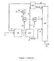
- Figure 1 is a schematic drawing of a prior art natural gas processing plant.
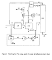
- Figure 2 is a schematic drawing of one aspect of the invention wherein a purge stream from a PSA is supplied to a lower demethanizer column feed.
- FIG. 3 is a schematic drawing of a second aspect of the invention wherein a purge stream from a PSA is supplied to a processing plant feed stream
- Demethanizer means a distillation column with a bottom reboiler, zero, one, or more than one side reboiler, and no condenser that separates methane from heavier hydrocarbons.
- NTL means natural gas liquids, defined as ethane and longer-chain hydrocarbons such as propane, butane and higher hydrocarbons (C 5 +).
- Raw natural gas means a feed to a gas processing plant that comprises NGL or at least one component of NGL.
- Raw natural gas is considered to already have CO 2 , H 2 S, N 2 , and H 2 O removed if needed.
- Typical properties of raw natural gas as it enters the gas processing plant are (compositions in mole percent): (a) pressure from about 700 to about 1200 psia, or from about 800 to about 1000 psia; (b) temperature typically close to ambient temperature; (c) methane concentration from about 65% to about 95%, or from about 80% to about 90%; (d) ethane concentration from about 3% to about 20%; (e) propane concentration from about 1% to about 10%; (f) butanes and higher hydrocarbon concentration up to about 10%; (f) carbon dioxide concentration up to about 2% (typically carbon dioxide is removed, such as by using an amine absorber column, in order to prevent freezing in the demethanizer column); (g) hydrogen sulfide concentration less than about 1 grain
- Porture quality gas means raw natural gas (as described above) that has had enough ethane, propane, butane, and heavier hydrocarbons removed to reach a composition suitable for sale into a pipeline as natural gas. In the case of NGL-rich feed gas this means reducing the higher heating value (HHV) of the gas to less than about 1100 BTU/standard cubic foot (SCF, typically using a reference state of 60 °F and 1 atmosphere pressure) to form this pipeline quality gas.
- HHV higher heating value
- Residue gas means gas from the demethanizer overhead, which may be recompressed and sold to natural gas pipelines.
- Figure 1 is an example of the Ortloff Gas-Subcooled Process (GSP) as described in patent US 4,157,904 ; hereby incorporated by reference.
- the Ortloff GSP is a typical NGL recovery process.
- the heat exchanger network can include exchangers with cold residue gas (such as that in column overhead 10) and/or external refrigerant such as propane and/or one or more demethanizer reboilers.
- Stream 3 then enters a flash separator 110 to separate the vapor and liquid phases.
- the overhead vapor exiting flash separator 110 is split into two streams.
- Stream 4 is chilled in a heat exchanger 120 against column overhead 10 and depressurized across a throttle valve to produce reflux stream 5 for demethanizer column 160.
- Stream 6 is expanded across turboexpander 130 to the demethanizer pressure and forms the main demethanizer feed 7.
- the bottoms of the flash separator 110, stream 8, is expanded across a throttle valve and feeds the demethanizer at a lower location
- the demethanizer 160 is a trayed or packed column with a reboiler (not shown) and potentially one or more side reboilers, but no condenser.
- Natural gas liquids (NGL) stream 15 leaves the bottom of the demethanizer and can be separated into higher purity products onsite or transported to a central fractionator.
- the cold residue gas in column overhead 10 is returned to near-ambient temperature in heat exchangers 120 and 100 before entering compressors 140 and 150 to return to pipeline pressure as stream 14.
- Compressor 140 is driven by turboexpander 130 and compressor 150 is driven by an electric motor, internal combustion engine, or a gas turbine.
- a fraction of feed 1 is diverted as stream 41 to adsorption unit 200.
- the adsorption unit 200 includes multiple adsorption beds, each packed with one or more layers of solid adsorbent.
- the adsorption unit 200 can comprise from about 4 to about 16 beds.
- the adsorption unit 200 is a pressure swing adsorption unit (PSA).
- PSAs comprising 5, 6, 10, and 12 beds were evaluated.
- Each adsorber vessel is subjected to a predefined sequence of process steps that effectively remove impurities from the feed gas during the high pressure feed step and then rejuvenate the adsorbent during the lower pressure regeneration steps.
- Continuous feed, product, and effluent flows are obtained by staggering the adsorber process steps over multiple adsorber beds.
- the sequence of process steps for each bed is completed over a period of from about 100 to about 600 seconds.
- Stream 41 is processed in the adsorption unit 200 via at least the following five steps:
- the product gas 42 which is enriched in methane and depleted in NGL, exits the bed at pipeline pressure with a low enough concentration of NGL to meet higher heating value and Wobbe index specifications to be sold into a pipeline as natural gas.
- the product gas 42 can therefore immediately enter the pipeline with no further treatment, compression, or heat exchange.
- Blowdown and purge gas effluent stream 43 which contains a higher concentration of heavy components, is compressed to demethanizer pressure by compressor 210.
- This purge gas stream has a typical composition, in mole percent, of from about 20% to about 50% methane, from about 25% to about 45% ethane, from about 15% to about 20% propane, and from about 10% to about 15% butane and higher hydrocarbons. It contains a higher level of heavier components than typical feed streams to the demethanizer.
- Stream 44 exits compressor 210 and is cooled by heat exchanger 220 to the same temperature as the flash separator 110.
- Resulting stream 45 enters the demethanizer with stream 9. Cooling is accomplished by heat exchange with any suitable process stream and/or propane refrigerant.
- adsorption unit 200 Operation of the adsorption unit 200 with multiple parallel beds and staggered process steps allows the overall purge and product flows to be smoothed out to minimize the impact on the gas processing plant.
- additional vessels can be added between the adsorption unit 200 and the downstream equipment to provide additional dampening of any gas flow or composition variations.
- Another aspect of the invention relates to modifying the sequence of adsorber process steps by recycling a portion of the blowdown and purge gas effluent stream 43 back to one of the adsorbers during a waste gas rinse step (not shown).
- the purpose of this step is to effectively displace additional adsorbed and interstitial methane to the product stream 42.
- This step is conducted either between steps 1 (Adsorption) and 2 (Pressure Equalization) or during step 2 after one of the one to six concurrent pressure equalization steps.
- the waste gas rinse stream is fed to the feed end of the adsorption unit 200 and comprises a portion of stream 43 compressed to feed pressure.
- adsorption unit 200 is a vacuum swing adsorption unit used to reduce the pressure during step 3 (Blowdown and Purge).
- the adsorption beds are depressurized by venting countercurrently to nearly atmospheric pressure, and then further depressurized countercurrently with a vacuum pump to a subatmospheric pressure.
- a small amount of the product gas from stream 42 or the purge gas stream is then used to countercurrently purge the beds at the same subatmospheric pressure. This approach uses less purge gas than a typical pressure swing adsorption unit.
- the adsorption unit 200 may be replaced with a membrane separation unit (not shown).
- the membrane separator is chosen such that it has a selectivity preferring ethane and propane over methane.
- the product gas 42 enriched in methane and depleted in NGL
- the effluent stream 43 containing a higher concentration of heavy hydrocarbon components
- FIG 3 shows another aspect of the invention wherein stream 43 is compressed to the same pressure as stream 1 and mixed with stream 2 prior to entering the heat exchanger 100.
- Heat exchanger 220 is used to remove the heat of compression so that the temperature of stream 45 is similar to the feed gas stream 1. This change has the overall effect of making the feed stream 2 slightly heavier.
- PSA performance was evaluated by determining the methane recovery (methane in the high pressure product gas divided by methane in the feed gas), ethane rejection (ethane in the low pressure waste gas divided by the ethane in the feed gas), and production capability of the PSA process (million standard cubic feet per day, MMSCFD, of feed gas handled per PSA train). All compositions are given in mole percentages.
- the feed gas contains 78.8% methane, 0.5% carbon dioxide, 11.4% ethane, 5.2% propane, 3.1 % butane, and 1.0% pentane at 120 °F and 68 atm (1000 psia).
- the feed gas flow rate is adjusted to yield 2% ethane in the high pressure product. Simulations are conducted at various purge gas flow rates to determine the optimum conditions for maximum methane recovery.
- the PSA beds simulated in this example were relatively short by typical standards for hydrogen separation.
- the packed length is about 8 feet rather than the more typical 20-30 feet of a hydrogen PSA system.
- the reduced length of these beds makes it possible to load them in a vertical orientation on a flatbed trailer or skid assembly that can be transported via conventional means.
- This is counterintuitive, as equilibrium-controlled PSA separation processes are typically operated with longer beds, with length to diameter ratios (UD) generally greater than 1.5, and preferably higher.
- UD value for the current PSA process is less than 1.5.
- Activated alumina (Alcan AA300) is packed in the PSA vessels, which are about 6 feet in diameter.
- the pressure equalization (PE) steps are controlled so at the end of each step there is a pressure difference between the bed providing PE and the one receiving it of about 0.1 atm.
- the PE step time is adjusted so the gas velocity in the bed providing PE is less than 50% of the velocity capable of fluidizing the adsorbent.
- the blowdown and purge steps are conducted at a pressure of 1.4 atm (20.6 psia).
- a PSA process utilizing 12 adsorber beds was simulated.
- the process cycle steps are outlined in Table 1, where "PE" designates a pressure equalization step.
- the cycle includes six pressure equalization steps, and two beds received feed gas at all times.
- Process performance is listed in Table 2.
- a single train of beds can process 30 MMSCFD feed gas and produce a product comprising methane with 2% ethane, 140 ppm CO 2 , and less than 700 ppm of C 3 and higher hydrocarbon components. Methane recovery to the high pressure product is 78.9%, and ethane and propane rejection levels are 88.9% and 99.4%, respectively.
- a PSA process utilizing 10 adsorber beds was simulated.
- the process cycle steps are outlined in Table 1.
- the cycle included four pressure equalization steps, and two beds received feed gas at all times.
- Process performance is listed in Table 2.
- a single train of beds can process 30.6 MMSCFD feed gas and produce a product comprising methane with 2% ethane, 130 ppm CO 2 , and less than 600 ppm of C 3 and higher hydrocarbon components.
- Methane recovery to the high pressure product is 75.1 %, and ethane and propane rejection levels are 89.4% and 99.6%, respectively.
- a PSA process utilizing 5 adsorber beds was simulated.
- the process cycle steps are outlined in Table 1.
- the cycle included two pressure equalization steps, and only one bed received feed gas at any time during the cycle.
- Process performance is listed in Table 2.
- a single train of beds can process 30.3 MMSCFD feed gas and produce a product comprising methane with 2% ethane, 250 ppm CO 2 , and less than 1600 ppm of C 3 and higher hydrocarbon components.
- Methane recovery to the high pressure product is 64.6%, and ethane and propane rejection levels are 90.9% and 99.0%, respectively.
- This example illustrates that using as little as five beds can yield high C 2 and C 3 rejection, but at about 18% lower methane recovery than the 12-bed process.
- Example 4 6-bed PSA process with partial waste gas rinse
- Simulations were conducted with a cycle similar to the 5-bed cycle described in Example 3, except that an additional high pressure rinse step is included between the feed and first pressure equalization steps. A portion of the low pressure waste gas collected from the blowdown and purge steps is compressed to feed pressure and used as the rinse gas. An additional bed is added to accommodate this step, so a 6-bed process is simulated.
- the cycle includes two pressure equalization steps and only one bed on feed gas at any time during the cycle. Bed length is 8 feet in these simulations.
- This example demonstrates the potential value of a rinse step using a portion of the PSA waste gas.
- the effectiveness of the instant invention was modeled using commercially available process modeling software from Aspen Technologies.
- the results for a 39 MMSCFD PSA are used to improve a 200 MMSCFD GSP plant.
- the PSA allows the plant to process about 228 MMSCFD while using the same compression power demand in the booster compressor and maintaining roughly the same vapor flow rate in the demethanizer column.
- Flow rates for plants including a PSA similar in configuration to those depicted in Figures 2 and 3 , as well as comparative flow rates for configurations without a PSA, are given in Table 4. All flow rates are in Ibmol/hr.
- Table 4 Simulated Flow Rates of Selected Process Streams Plant with no PSA Stream 1 Stream 14 Stream 15 methane 17050 16990 60 ethane 2450 80 2370 propane 1120 2 1118 Plant with PSA - consistent with Figure 2 Stream 1 Stream 14 Stream 15 Stream 41 Stream 42 Stream 43 methane 19430 16660 70 3330 2700 630 ethane 2790 100 2640 480 55 425 propane 1275 2 1273 220 0 220 Plant with PSA - consistent with Figure 3 Stream 1 Stream 14 Stream 15 Stream 41 Stream 42 Stream 43 methane 19430 16670 65 3330 2700 630 ethane 2790 120 2610 480 55 425 propane 1275 3 1272 220 0 220
- the effectiveness of the instant invention was modeled using commercially available process modeling software from Aspen Technologies.
- the results for a 50 MMSCFD membrane with a selectivity of ethane over methane of 2.5 and propane over ethane of 6.0 are used to improve a 200 MMSCFD GSP plant.
- the membrane allows the plant to process about 230 MMSCFD while using the same compression power demand in the booster compressor and maintaining roughly the same vapor flow rate in the demethanizer column.
- Flow rates for plants including a membrane separator similar in configuration to those depicted in Figures 2 and 3 , as well as comparative flow rates for configurations without a membrane separator, are given in Table 5. All flow rates are in lbmol/hr.
- Table 5 Simulated Flow Rates of Selected Process Streams Plant with no PSA Stream 1 Stream 14 Stream 15 methane 17050 16990 60 ethane 2450 80 2370 propane 1120 2 1118 Plant with PSA - consistent with Figure 2 Stream 1 Stream 14 Stream 15 Stream 41 Stream 42 Stream 43 methane 19980 17740 60 4630 2180 2180 ethane 2870 275 2480 625 115 510 propane 1310 10 1300 285 5 280 Plant with PSA - consistent with Figure 3 Stream 1 Stream 14 Stream 15 Stream 41 Stream 42 Stream 43 methane 19980 17740 60 4360 2180 2180 ethane 2870 275 2480 625 115 510 propane 1310 10 1300 285 5 280
Landscapes
- Engineering & Computer Science (AREA)
- Chemical & Material Sciences (AREA)
- Oil, Petroleum & Natural Gas (AREA)
- Mechanical Engineering (AREA)
- Thermal Sciences (AREA)
- General Engineering & Computer Science (AREA)
- Physics & Mathematics (AREA)
- Chemical Kinetics & Catalysis (AREA)
- General Chemical & Material Sciences (AREA)
- Organic Chemistry (AREA)
- Separation By Low-Temperature Treatments (AREA)
- Organic Low-Molecular-Weight Compounds And Preparation Thereof (AREA)
- Separation Of Gases By Adsorption (AREA)
Applications Claiming Priority (2)
| Application Number | Priority Date | Filing Date | Title |
|---|---|---|---|
| US201161514081P | 2011-08-02 | 2011-08-02 | |
| US13/555,680 US9945608B2 (en) | 2011-08-02 | 2012-07-23 | Natural gas processing plant |
Publications (2)
| Publication Number | Publication Date |
|---|---|
| EP2554637A2 true EP2554637A2 (de) | 2013-02-06 |
| EP2554637A3 EP2554637A3 (de) | 2013-02-13 |
Family
ID=46640527
Family Applications (1)
| Application Number | Title | Priority Date | Filing Date |
|---|---|---|---|
| EP12005598A Ceased EP2554637A3 (de) | 2011-08-02 | 2012-08-01 | Anlage zur Aufbereitung von rohem Erdgas |
Country Status (5)
| Country | Link |
|---|---|
| US (1) | US9945608B2 (de) |
| EP (1) | EP2554637A3 (de) |
| CN (1) | CN103087794B (de) |
| AU (1) | AU2012208988B2 (de) |
| CA (1) | CA2784367C (de) |
Cited By (2)
| Publication number | Priority date | Publication date | Assignee | Title |
|---|---|---|---|---|
| WO2015112198A1 (en) * | 2014-01-23 | 2015-07-30 | Dow Global Technologies Llc | Method to provide pipeline quality natural gas |
| RU2794123C1 (ru) * | 2023-02-03 | 2023-04-11 | Общество с ограниченной ответственностью научно-исследовательский и проектный институт "ПЕГАЗ" | Система циркуляции криогенного хладагента и подачи острого орошения |
Families Citing this family (28)
| Publication number | Priority date | Publication date | Assignee | Title |
|---|---|---|---|---|
| US10451344B2 (en) | 2010-12-23 | 2019-10-22 | Fluor Technologies Corporation | Ethane recovery and ethane rejection methods and configurations |
| US10036590B2 (en) * | 2012-08-02 | 2018-07-31 | Air Products And Chemicals, Inc. | Helium recovery from streams containing helium, carbon dioxide, and at least one of nitrogen and methane |
| US20140075987A1 (en) | 2012-09-20 | 2014-03-20 | Fluor Technologies Corporation | Configurations and methods for ngl recovery for high nitrogen content feed gases |
| US20140366577A1 (en) | 2013-06-18 | 2014-12-18 | Pioneer Energy Inc. | Systems and methods for separating alkane gases with applications to raw natural gas processing and flare gas capture |
| WO2015123257A1 (en) * | 2014-02-11 | 2015-08-20 | Tech 3 Solutions, Inc. | Apparatus for flare gas processing and use |
| US10006701B2 (en) | 2016-01-05 | 2018-06-26 | Fluor Technologies Corporation | Ethane recovery or ethane rejection operation |
| US10330382B2 (en) | 2016-05-18 | 2019-06-25 | Fluor Technologies Corporation | Systems and methods for LNG production with propane and ethane recovery |
| US20190257579A9 (en) * | 2016-05-27 | 2019-08-22 | Jl Energy Transportation Inc. | Integrated multi-functional pipeline system for delivery of chilled mixtures of natural gas and chilled mixtures of natural gas and ngls |
| CA3033088C (en) | 2016-09-09 | 2025-05-13 | Fluor Technologies Corporation | PROCESSES AND CONFIGURATION FOR REASPRACTING AN LNG PLANT FOR ETHANUM RECOVERY |
| CA3077409C (en) | 2017-10-20 | 2025-05-13 | Fluor Technologies Corporation | Phased Implementation of Natural Gas Liquid Recovery Plants |
| EP3499159A1 (de) * | 2017-12-12 | 2019-06-19 | Linde Aktiengesellschaft | Verfahren und anlage zur herstellung von flüssigerdgas |
| CN108587711A (zh) * | 2018-04-24 | 2018-09-28 | 辽宁石油化工大学 | 一种四级一体模式的油田伴生气除杂的方法及装置 |
| US10760006B2 (en) * | 2018-07-02 | 2020-09-01 | Dow Global Technologies Llc | Methods and systems to separate hydrocarbon mixtures such as natural gas into light and heavy components |
| US10760010B2 (en) * | 2018-07-02 | 2020-09-01 | Dow Global Technologies Llc | Methods and systems to separate hydrocarbon mixtures such as natural gas into light and heavy components |
| US12215922B2 (en) | 2019-05-23 | 2025-02-04 | Fluor Technologies Corporation | Integrated heavy hydrocarbon and BTEX removal in LNG liquefaction for lean gases |
| US12098882B2 (en) * | 2018-12-13 | 2024-09-24 | Fluor Technologies Corporation | Heavy hydrocarbon and BTEX removal from pipeline gas to LNG liquefaction |
| US11149905B2 (en) | 2019-10-03 | 2021-10-19 | Saudi Arabian Oil Company | Mobile natural gas storage and transportation unit based on adsorption |
| CA3158563A1 (en) * | 2019-11-19 | 2021-05-27 | William B. Dolan | Systems and processes for heavy hydrocarbon removal |
| MX2022013673A (es) * | 2020-05-01 | 2022-11-30 | Basf Corp | Lecho adsorbente con estabilidad hidrotermica aumentada. |
| US12025373B2 (en) | 2020-08-16 | 2024-07-02 | Gtuit, Llc | System and method for treating associated gas |
| US20210055046A1 (en) * | 2020-11-11 | 2021-02-25 | Waga Energy | Facility For Producing Gaseous Methane By Purifying Biogas From Landfill, Combining Membranes And Cryogenic Distillation For Landfill Biogas Upgrading |
| CN114591131A (zh) * | 2020-12-04 | 2022-06-07 | 中国石油天然气股份有限公司 | 一种回收甲烷的装置和方法 |
| EP4381030A4 (de) | 2021-09-09 | 2025-09-03 | Coldstream Energy Ip Llc | Tragbares druckwechseladsorptionsverfahren und system zur brenngaskonditionierung |
| CN114317053B (zh) * | 2021-12-31 | 2025-10-17 | 北京北科欧远科技有限公司 | 焦炉气与二氧化碳制低碳甲醇联产液化天然气方法和设备 |
| CN114561235B (zh) * | 2022-01-11 | 2022-12-13 | 广东省氢一能源科技有限公司 | 一种基于压力能回收的氢气天然气混输与分离装置及方法 |
| US20230375263A1 (en) * | 2022-05-17 | 2023-11-23 | Gas Liquids Engineering Ltd. | Gas processing methodology utilizing reflux and additionally synthesized stream optimization |
| WO2024054552A2 (en) * | 2022-09-07 | 2024-03-14 | Wm Intellectual Property Holdings, L.L.C. | System and method for control of feed compressors in an rng recovery facility for biogas or landfill gas |
| CN116785885A (zh) * | 2023-03-23 | 2023-09-22 | 科貝森(沈阳)能源科技有限责任公司 | 一种撬装式煤层气甲烷浓缩真空变压吸附装置 |
Citations (7)
| Publication number | Priority date | Publication date | Assignee | Title |
|---|---|---|---|---|
| US4157904A (en) | 1976-08-09 | 1979-06-12 | The Ortloff Corporation | Hydrocarbon gas processing |
| US5171333A (en) | 1990-01-09 | 1992-12-15 | Uop | Methane purification by pressure swing adsorption |
| US5840099A (en) | 1997-09-16 | 1998-11-24 | Air Products And Chemicals, Inc. | Process for the removal of water, CO2, ethane and C3 + hydrocarbons from a gas stream |
| US6444012B1 (en) | 2000-10-30 | 2002-09-03 | Engelhard Corporation | Selective removal of nitrogen from natural gas by pressure swing adsorption |
| US6497750B2 (en) | 2001-02-26 | 2002-12-24 | Engelhard Corporation | Pressure swing adsorption process |
| US7396388B2 (en) | 2005-07-06 | 2008-07-08 | Basf Catalysts Llc | Integrated heavy hydrocarbon removal, amine treating and dehydration |
| US20080282884A1 (en) | 2007-05-18 | 2008-11-20 | Kelley Bruce T | Removal of heavy hydrocarbons from gas mixtures containing heavy hydrocarbons and methane |
Family Cites Families (10)
| Publication number | Priority date | Publication date | Assignee | Title |
|---|---|---|---|---|
| US3735600A (en) | 1970-05-11 | 1973-05-29 | Gulf Research Development Co | Apparatus and process for liquefaction of natural gases |
| US5689032A (en) * | 1994-11-22 | 1997-11-18 | Krause/Pasadyn, A Partnership | Method and apparatus for recovery of H2 and C2 and heavier components |
| US6020481A (en) | 1996-04-01 | 2000-02-01 | The Perkin-Elmer Corporation | Asymmetric benzoxanthene dyes |
| US5772733A (en) * | 1997-01-24 | 1998-06-30 | Membrane Technology And Research, Inc. | Natural gas liquids (NGL) stabilization process |
| US6610124B1 (en) | 2002-03-12 | 2003-08-26 | Engelhard Corporation | Heavy hydrocarbon recovery from pressure swing adsorption unit tail gas |
| WO2004015347A2 (en) * | 2002-08-08 | 2004-02-19 | Pacific Consolidated Industries, L.P. | Nitrogen generator |
| US7479227B2 (en) * | 2003-03-07 | 2009-01-20 | Membrane Technology And Research, Inc. | Liquid-phase separation of low molecular weight organic compounds |
| CN100339671C (zh) * | 2003-05-27 | 2007-09-26 | 西安联合超滤净化设备有限公司 | 低压普冷法分离气体混合物中凝析液的方法 |
| US20060191410A1 (en) | 2005-02-28 | 2006-08-31 | Dolan William B | NGL trap-method for recovery of heavy hydrocarbon from natural gas |
| CN101760270B (zh) * | 2010-01-14 | 2014-01-08 | 党延斋 | 脱除并回收天然气中co2的方法 |
-
2012
- 2012-07-23 US US13/555,680 patent/US9945608B2/en active Active
- 2012-07-30 AU AU2012208988A patent/AU2012208988B2/en not_active Ceased
- 2012-08-01 EP EP12005598A patent/EP2554637A3/de not_active Ceased
- 2012-08-01 CA CA2784367A patent/CA2784367C/en active Active
- 2012-08-02 CN CN201210433233.1A patent/CN103087794B/zh not_active Expired - Fee Related
Patent Citations (8)
| Publication number | Priority date | Publication date | Assignee | Title |
|---|---|---|---|---|
| US4157904A (en) | 1976-08-09 | 1979-06-12 | The Ortloff Corporation | Hydrocarbon gas processing |
| US5171333A (en) | 1990-01-09 | 1992-12-15 | Uop | Methane purification by pressure swing adsorption |
| US5840099A (en) | 1997-09-16 | 1998-11-24 | Air Products And Chemicals, Inc. | Process for the removal of water, CO2, ethane and C3 + hydrocarbons from a gas stream |
| US6444012B1 (en) | 2000-10-30 | 2002-09-03 | Engelhard Corporation | Selective removal of nitrogen from natural gas by pressure swing adsorption |
| US6497750B2 (en) | 2001-02-26 | 2002-12-24 | Engelhard Corporation | Pressure swing adsorption process |
| US7396388B2 (en) | 2005-07-06 | 2008-07-08 | Basf Catalysts Llc | Integrated heavy hydrocarbon removal, amine treating and dehydration |
| US7442233B2 (en) | 2005-07-06 | 2008-10-28 | Basf Catalysts Llc | Integrated heavy hydrocarbon removal, amine treating and dehydration |
| US20080282884A1 (en) | 2007-05-18 | 2008-11-20 | Kelley Bruce T | Removal of heavy hydrocarbons from gas mixtures containing heavy hydrocarbons and methane |
Non-Patent Citations (2)
| Title |
|---|
| AVILA ET AL.: "Extraction of ethane from natural gas at high pressure by adsorption on Na-ETS-10", CHEM. ENG. SCI., vol. 66, 2011, pages 2991 - 2996, XP028205330, DOI: doi:10.1016/j.ces.2011.03.057 |
| KUMAR, R. ET AL.: "A Versatile Process Simulator for Adsorptive Separations", CHEM. ENG. SCI., 1994, pages 3115, XP008091201, DOI: doi:10.1016/0009-2509(94)E0085-5 |
Cited By (2)
| Publication number | Priority date | Publication date | Assignee | Title |
|---|---|---|---|---|
| WO2015112198A1 (en) * | 2014-01-23 | 2015-07-30 | Dow Global Technologies Llc | Method to provide pipeline quality natural gas |
| RU2794123C1 (ru) * | 2023-02-03 | 2023-04-11 | Общество с ограниченной ответственностью научно-исследовательский и проектный институт "ПЕГАЗ" | Система циркуляции криогенного хладагента и подачи острого орошения |
Also Published As
| Publication number | Publication date |
|---|---|
| AU2012208988A1 (en) | 2013-02-21 |
| CA2784367C (en) | 2017-04-04 |
| CN103087794B (zh) | 2016-02-10 |
| EP2554637A3 (de) | 2013-02-13 |
| CA2784367A1 (en) | 2013-02-02 |
| US20130186133A1 (en) | 2013-07-25 |
| CN103087794A (zh) | 2013-05-08 |
| AU2012208988B2 (en) | 2014-07-10 |
| US9945608B2 (en) | 2018-04-17 |
Similar Documents
| Publication | Publication Date | Title |
|---|---|---|
| US9945608B2 (en) | Natural gas processing plant | |
| CA3054907C (en) | Helium extraction from natural gas | |
| CA2840723C (en) | Natural gas liquefaction process | |
| US10441915B2 (en) | Natural gas liquids recovery from pressure swing adsorption and vacuum swing adsorption | |
| AU2007238976B2 (en) | Membrane process for LPG recovery | |
| EP2880134B1 (de) | Entfernung schwerer kohlenwasserstoffe aus einem erdgasstrom | |
| US10760010B2 (en) | Methods and systems to separate hydrocarbon mixtures such as natural gas into light and heavy components | |
| US7337631B2 (en) | Use of cryogenic temperatures in processing gases containing light components with physical solvents | |
| WO2011059451A1 (en) | Multi-stage adsorption system for gas mixture separation | |
| US20240019206A1 (en) | Cryogenic process for recovering valuable components from a hydrogen-rich feed gas | |
| US10730005B2 (en) | Porous materials for natural gas liquids separations | |
| US10760006B2 (en) | Methods and systems to separate hydrocarbon mixtures such as natural gas into light and heavy components | |
| CA3078066C (en) | Porous materials for natural gas liquids separations |
Legal Events
| Date | Code | Title | Description |
|---|---|---|---|
| PUAL | Search report despatched |
Free format text: ORIGINAL CODE: 0009013 |
|
| PUAI | Public reference made under article 153(3) epc to a published international application that has entered the european phase |
Free format text: ORIGINAL CODE: 0009012 |
|
| AK | Designated contracting states |
Kind code of ref document: A2 Designated state(s): AL AT BE BG CH CY CZ DE DK EE ES FI FR GB GR HR HU IE IS IT LI LT LU LV MC MK MT NL NO PL PT RO RS SE SI SK SM TR |
|
| AX | Request for extension of the european patent |
Extension state: BA ME |
|
| AK | Designated contracting states |
Kind code of ref document: A3 Designated state(s): AL AT BE BG CH CY CZ DE DK EE ES FI FR GB GR HR HU IE IS IT LI LT LU LV MC MK MT NL NO PL PT RO RS SE SI SK SM TR |
|
| AX | Request for extension of the european patent |
Extension state: BA ME |
|
| RIC1 | Information provided on ipc code assigned before grant |
Ipc: C10L 3/10 20060101AFI20130110BHEP |
|
| 17P | Request for examination filed |
Effective date: 20130812 |
|
| RBV | Designated contracting states (corrected) |
Designated state(s): AL AT BE BG CH CY CZ DE DK EE ES FI FR GB GR HR HU IE IS IT LI LT LU LV MC MK MT NL NO PL PT RO RS SE SI SK SM TR |
|
| 17Q | First examination report despatched |
Effective date: 20140115 |
|
| STAA | Information on the status of an ep patent application or granted ep patent |
Free format text: STATUS: THE APPLICATION HAS BEEN REFUSED |
|
| 18R | Application refused |
Effective date: 20180109 |