EP2554308A1 - Jig and method for modifying casing in turbine system - Google Patents
Jig and method for modifying casing in turbine system Download PDFInfo
- Publication number
- EP2554308A1 EP2554308A1 EP12178545A EP12178545A EP2554308A1 EP 2554308 A1 EP2554308 A1 EP 2554308A1 EP 12178545 A EP12178545 A EP 12178545A EP 12178545 A EP12178545 A EP 12178545A EP 2554308 A1 EP2554308 A1 EP 2554308A1
- Authority
- EP
- European Patent Office
- Prior art keywords
- jig
- casing
- machining
- passage
- alignment
- Prior art date
- Legal status (The legal status is an assumption and is not a legal conclusion. Google has not performed a legal analysis and makes no representation as to the accuracy of the status listed.)
- Granted
Links
Images




Classifications
-
- B—PERFORMING OPERATIONS; TRANSPORTING
- B23—MACHINE TOOLS; METAL-WORKING NOT OTHERWISE PROVIDED FOR
- B23B—TURNING; BORING
- B23B47/00—Constructional features of components specially designed for boring or drilling machines; Accessories therefor
- B23B47/28—Drill jigs for workpieces
-
- F—MECHANICAL ENGINEERING; LIGHTING; HEATING; WEAPONS; BLASTING
- F01—MACHINES OR ENGINES IN GENERAL; ENGINE PLANTS IN GENERAL; STEAM ENGINES
- F01D—NON-POSITIVE DISPLACEMENT MACHINES OR ENGINES, e.g. STEAM TURBINES
- F01D25/00—Component parts, details, or accessories, not provided for in, or of interest apart from, other groups
- F01D25/24—Casings; Casing parts, e.g. diaphragms, casing fastenings
-
- B—PERFORMING OPERATIONS; TRANSPORTING
- B23—MACHINE TOOLS; METAL-WORKING NOT OTHERWISE PROVIDED FOR
- B23B—TURNING; BORING
- B23B2215/00—Details of workpieces
- B23B2215/76—Components for turbines
-
- B—PERFORMING OPERATIONS; TRANSPORTING
- B23—MACHINE TOOLS; METAL-WORKING NOT OTHERWISE PROVIDED FOR
- B23B—TURNING; BORING
- B23B2247/00—Details of drilling jigs
-
- B—PERFORMING OPERATIONS; TRANSPORTING
- B23—MACHINE TOOLS; METAL-WORKING NOT OTHERWISE PROVIDED FOR
- B23B—TURNING; BORING
- B23B2247/00—Details of drilling jigs
- B23B2247/12—Drilling jigs with means to affix the jig to the workpiece
-
- B—PERFORMING OPERATIONS; TRANSPORTING
- B23—MACHINE TOOLS; METAL-WORKING NOT OTHERWISE PROVIDED FOR
- B23B—TURNING; BORING
- B23B49/00—Measuring or gauging equipment on boring machines for positioning or guiding the drill; Devices for indicating failure of drills during boring; Centering devices for holes to be bored
- B23B49/02—Boring templates or bushings
-
- F—MECHANICAL ENGINEERING; LIGHTING; HEATING; WEAPONS; BLASTING
- F05—INDEXING SCHEMES RELATING TO ENGINES OR PUMPS IN VARIOUS SUBCLASSES OF CLASSES F01-F04
- F05D—INDEXING SCHEME FOR ASPECTS RELATING TO NON-POSITIVE-DISPLACEMENT MACHINES OR ENGINES, GAS-TURBINES OR JET-PROPULSION PLANTS
- F05D2230/00—Manufacture
- F05D2230/60—Assembly methods
- F05D2230/64—Assembly methods using positioning or alignment devices for aligning or centring, e.g. pins
-
- Y—GENERAL TAGGING OF NEW TECHNOLOGICAL DEVELOPMENTS; GENERAL TAGGING OF CROSS-SECTIONAL TECHNOLOGIES SPANNING OVER SEVERAL SECTIONS OF THE IPC; TECHNICAL SUBJECTS COVERED BY FORMER USPC CROSS-REFERENCE ART COLLECTIONS [XRACs] AND DIGESTS
- Y10—TECHNICAL SUBJECTS COVERED BY FORMER USPC
- Y10T—TECHNICAL SUBJECTS COVERED BY FORMER US CLASSIFICATION
- Y10T29/00—Metal working
- Y10T29/49—Method of mechanical manufacture
- Y10T29/49229—Prime mover or fluid pump making
- Y10T29/49236—Fluid pump or compressor making
- Y10T29/49238—Repairing, converting, servicing or salvaging
-
- Y—GENERAL TAGGING OF NEW TECHNOLOGICAL DEVELOPMENTS; GENERAL TAGGING OF CROSS-SECTIONAL TECHNOLOGIES SPANNING OVER SEVERAL SECTIONS OF THE IPC; TECHNICAL SUBJECTS COVERED BY FORMER USPC CROSS-REFERENCE ART COLLECTIONS [XRACs] AND DIGESTS
- Y10—TECHNICAL SUBJECTS COVERED BY FORMER USPC
- Y10T—TECHNICAL SUBJECTS COVERED BY FORMER US CLASSIFICATION
- Y10T408/00—Cutting by use of rotating axially moving tool
- Y10T408/55—Cutting by use of rotating axially moving tool with work-engaging structure other than Tool or tool-support
- Y10T408/567—Adjustable, tool-guiding jig
-
- Y—GENERAL TAGGING OF NEW TECHNOLOGICAL DEVELOPMENTS; GENERAL TAGGING OF CROSS-SECTIONAL TECHNOLOGIES SPANNING OVER SEVERAL SECTIONS OF THE IPC; TECHNICAL SUBJECTS COVERED BY FORMER USPC CROSS-REFERENCE ART COLLECTIONS [XRACs] AND DIGESTS
- Y10—TECHNICAL SUBJECTS COVERED BY FORMER USPC
- Y10T—TECHNICAL SUBJECTS COVERED BY FORMER US CLASSIFICATION
- Y10T408/00—Cutting by use of rotating axially moving tool
- Y10T408/55—Cutting by use of rotating axially moving tool with work-engaging structure other than Tool or tool-support
- Y10T408/567—Adjustable, tool-guiding jig
- Y10T408/568—Guide bushing
Definitions
- the present disclosure relates in general to turbine systems, and more particularly to methods and apparatus for modifying the casings of turbine systems.
- Turbine systems are widely utilized in fields such as power generation.
- a conventional gas turbine system includes a compressor section, a combustor section, and at least one turbine section.
- the compressor section is configured to compress air as the air flows through the compressor section.
- the air is then flowed from the compressor section to the combustor section, where it is mixed with fuel and combusted, generating a hot gas flow.
- the hot gas flow is provided to the turbine section, which utilizes the hot gas flow by extracting energy from it to power the compressor, an electrical generator, and other various loads.
- various probes are utilized to measure the performance of a turbine system.
- various preparations are made for mounting the probes in various locations on a turbine system.
- spot faces are machined into the components.
- the spot faces are various areas where probes could be mounted to the system.
- holes are machined through the spot faces to facilitate the mounting of the various probes. These holes are then typically plugged for normal operation of the system.
- various locations may be chosen for mounting of a probe or probes. These locations may vary dependent on the desired tests needed to be performed for an individual system or other various parameters.
- a location is chosen, a probe is mounted through a spot face in that location. Further, in order for the probe to provide accurate and consistent data, the probe must be precisely installed.
- an improved apparatus and method for modifying a casing or other component of a turbine system would be desired.
- an apparatus and method that allow for in-field modification of a casing or other component would be advantageous.
- the invention resides in a jig for modifying a casing in a turbine system.
- the jig includes a body and a protrusion extending from the body.
- the protrusion is configured for engaging a hole defined in a spot face on the casing.
- the jig further includes at least one machining passage defined in the body, the machining passage provided for machining the casing therethrough, and at least one alignment feature configured on the body, the at least one alignment feature provided for aligning the jig with respect to the casing.
- the invention resides in a method for modifying a casing in a turbine system.
- the method includes engaging a jig with a hole defined in a spot face on the casing.
- the jig includes at least one machining passage and at least one alignment feature.
- the method further includes aligning the jig with respect to the casing, and machining at least one installation hole into the casing through the spot face.
- FIG. 1 is a schematic diagram of a turbine system 10.
- the system 10 may include a compressor 12, combustor 14, and turbine 16. Further, the system 10 may include a plurality of compressors 12, combustors 14, and turbines 16. The compressor 12 and turbine 16 may be coupled by a shaft 18.
- the shaft 18 may be a single shaft or a plurality of shaft segments coupled together to form shaft 18. It should be understood that the turbine system according to the present disclosure may be a gas turbine system, a steam turbine system, or any other suitable turbine system.
- FIGS. 2 and 3 illustrate one embodiment of a casing 30.
- the casing 30 is located in the turbine system 10, and surrounds various components in a section of the turbine system 10, such as stator and rotor components.
- the casing 30 may be for a compressor 12, a turbine 16, or any other suitable section of the system 10.
- a plurality of spot faces 32 may be machined into or otherwise provided on the casing 30 during or after manufacturing.
- a spot face 32 is a generally planar surface on the exterior of the casing 30, as shown.
- spot faces 32 in various locations on the casing 30 that may be utilized before, during, or after operation of the system for various purposes, such as testing of the system 10.
- spot faces 32 may include holes 34 defined therein to facilitate such modification.
- Each hole may have an inner width or diameter 36, and in exemplary embodiments may have a threaded inner wall 38.
- the holes 34 are typically plugged during operation of the system 10, but may be unplugged as required for modification of a spot face 32.
- One purpose requiring modification of a spot face 32 is the use of various probes to conduct various tests on the system 10.
- various probes For example, clearance probes, proximity probes, or any other suitable probes may be utilized in the system to conduct various tests and provide various data regarding the performance of the system 10.
- a probe must typically be precisely placed with respect to the spot face 32 and casing 30 in order for it to provide accurate, reliable data.
- a jig 50 is provided for modifying a casing 30 in a turbine system 10.
- the jig 50 is provided for precisely and accurately modifying a spot face 32 such that a probe can be precisely mounted thereon.
- the jig 50 according to the present disclosure advantageously allows for in-field modification of the casing 30. Thus, expensive and time-consuming transportation of the casing 30 to a facility in order to modify a spot face 32 is avoided.
- jig 50 includes a body 52 and a protrusion 54 extending from the body 52. While the body 52 illustrated in FIGS. 4 through 9 is cylindrical, it should be understood that the body 52 may have any suitable shape and size capable of housing the various features discussed herein. Further, the body in exemplary embodiments fits within a spot face 32.
- Protrusion 54 extends from the body 52.
- the protrusion 54 may be integral with the body 52 and thus extend therefrom, or may be a separate component from the body 52 that is fastened thereon.
- the protrusion 54 may be a generally central protrusion 54, thus extending from a central location on a surface of the body 52.
- the protrusion 54 has an outer width or diameter 56, and extends along axis 58, as shown in FIGS. 6 and 7 .
- Axis 58 in exemplary embodiments is generally perpendicular to a surface of the body 52 from which the protrusion extends.
- the protrusion 54 has a threaded outer surface 59.
- the protrusion 54 is further configured for engaging the hole 34 defined in the spot face 32 on the casing 30.
- the hole 34 may have a certain cross-sectional shape, such as circular, square, rectangular, oval, triangular, or any other suitable polygonal shape, and size.
- the protrusion 54 may have a similar shape and size such that it may fit into the hole 34.
- the shape and size of the protrusion 54 is substantially identical to the shape and size of the hole 34, such that the protrusion 54 fits relatively snugly within the hole 34.
- the outer width or diameter 56 of the protrusion 54 as shown in FIGS. 6 and 7 , may be substantially identical to the inner width or diameter 36 of the hole 34.
- the protrusion 54 and hole 34 are threaded, as shown by threaded inner wall 38 and threaded outer surface 59 in FIGS. 6 and 7 .
- the threaded outer surface 59 of protrusion 54 may engage the threaded inner wall 38 of the mating hole 34 when the protrusion 54 is engaged in the hole 34, and engagement of the protrusion 54 in the hole 34 may involve screwing the protrusion 54 into the hole 34 to engage the mating threads.
- the jig 50 further includes at least one machining passage 60.
- Each machining passage 60 is defined in the body 52. Further, the machining passages 60 may be positioned in an array within the body 52. Such array may, in some embodiments, peripherally surround the protrusion 54. Any number of machining passages 60 may be included in the jig 50. For example, while in exemplary embodiments three passages 60 are defined in the body, it should be understood that one, two, four, five, or more passages may alternatively be defined. Further, in some embodiments, the passages 60 may be approximately equally spaced apart from each other in an array. For example, in embodiments wherein there are three passages 60, the passages 60 may be spaced 120° apart. If there are two passages 60, the passages 60 may be spaced 180° apart, while if there are four passages 60, the passages 60 may be spaced 90° apart, and so on.
- the machining passages 60 are defined parallel to the central protrusion 54.
- the machining passages 60 may extend through the body 52 parallel to axis 58 of the protrusion 54.
- the machining passages 60 may extend at any suitable angle with respect to axis 58.
- each machining passage 60 may have an inner width or diameter 62.
- the machining passages 60 are provided in jig 50 for machining installation holes 64 into the casing 30 through a spot face 32.
- an installation hole 64 may be drilled through a machining passage 60 into the casing 30 and, optionally, tapped. Such machining of an installation hole 64 using a machining passage 60 allows for the installation hole 64 to be precisely positioned and oriented.
- the installation hole 64 may be utilized to mount or otherwise install a probe onto the casing 30.
- a stud for the probe may be installed within the installation hole 64, and the probe installed by attaching to the stud or otherwise securing in place.
- the jig 50 may include at least one bushing 70. Further, in exemplary embodiments, one or more bushings 70 may be provided for each machining passage 60. Each bushing 70 is configured to engage a machining passage 60.
- a passage 60 may have a certain cross-sectional shape, such as circular, square, rectangular, oval, triangular, or any other suitable polygonal shape, and size.
- the bushing 70 may have a similar shape and size such that it may fit into a passage 60.
- the shape and size of the bushing 70 is substantially identical to the shape and size of the passage 60, such that the bushing 70 fits relatively snugly within the passage 60.
- the outer width or diameter 72 of the bushing 70 as shown in FIG. 9 , may be substantially identical to the inner width or diameter 62 of a passage 60.
- each bushing 70 defines a passage 74 therethrough, as shown in FIG. 8 .
- the passage 74 has an inner width or diameter 76.
- the passage 74 is designed for receiving a drill bit or other suitable machining device therethrough for drilling or otherwise machining an installation hole 62.
- the passage 74 may thus be optimally sized, with a suitable inner width or diameter 76, such that the drill bit or other suitable machining device is precisely oriented and aligned therein.
- the bushings 70 may be coupled to the jig 50.
- mating bores 80 and 82 may be defined in the body 52 and bushing 70, respectively.
- a wire, chain, or other suitable coupling apparatus 84 may be run through the bores 80 and 82 to couple a bushing 70 to the jig 50.
- machining of an installation hole 64 may include drilling and tapping the hole 64 through a machining passage 60 defined in the jig.
- the bushing 70 may be engaged in the machine passage 60 to drill the hole 64, and then disengaged from the machine passage 60 to tap the hole 64.
- a bushing 70 or multiple bushings 70, such as bushings 70 having various inner diameters 76, may be utilized to drill and tap the hole 64, or the hole 64 may be drilled and tapped without the use of any bushing 70.
- the jig 50 further includes at least one alignment feature 90.
- Each alignment feature 90 is configured on the body 52.
- an alignment feature 90 may include an alignment passage 92 defined in the body 52 and an alignment pin 94 associated with the alignment passage 92.
- the alignment passage 92 may have a threaded inner wall 96 and the alignment pin 94 may have a mating threaded outer surface 98.
- the alignment pin 94 may be, for example, a screw or other suitable threaded component.
- Each alignment feature 90 may be provided for aligning the jig 50 with respect to the casing 30.
- the alignment features 90 may secure the jig 50 in this position to provide a precise alignment of the jig 50.
- the alignment feature 90 includes an alignment passage 92 and associated alignment pin 94
- the alignment pin 94 is engaged with the passage 92 and into contact with the spot face 32.
- the alignment pin 94 may be screwed into the passage 92 such that the threads of the passage 92 and pin 94 are engaged and until the pin 94 contacts the spot face 32.
- each pin 94 may be engaged to a specified torque, if desired or required. Engagement of the pins 94 with the spot face 32 may securely align the jig 50. For example, engagement of the pins 94 may tension the engagement between the protrusion 54 and the hole 34, such as the threaded engagement between the threaded inner wall 38 and the threaded outer surface 59. This tension may securely align the jig 50 with respect to the casing 30, thus preventing or reducing the risk of movement of the jig 50 with respect to the casing 30.
- an exemplary alignment feature 90 includes an alignment passage 92 and alignment pin 94, any suitable component for aligning the jig 50 may further be considered an alignment feature within the scope and spirit of the present disclosure.
- the alignment features 90 may be positioned in an array about or within the body 52. Such array may, in some embodiments, peripherally surround the protrusion 54. Any number of alignment features 90 may be included in the jig 50. For example, while in exemplary embodiments three alignment features 90 are defined in the body, it should be understood that one, two, four, five, or more alignment features 90 may alternatively be defined. Further, in some embodiments, the alignment features 90 may be approximately equally spaced apart from each other in an array. For example, in embodiments wherein there are three alignment features 90, the alignment features 90 may be spaced 120° apart. If there are two alignment features 90, the alignment features 90 may be spaced 180° apart, while if there are four alignment features 90, the alignment features 90 may be spaced 90° apart, and so on.
- the alignment features 90 are defined parallel to the central protrusion 54.
- the alignment features 90 may extend through the body 52 parallel to axis 58 of the protrusion 54.
- the alignment features 90 may extend at any suitable angle with respect to axis 58.
- the jig 50 may further include at least one orientation feature 100.
- the orientation feature 100 may be provided for orienting the jig 50 with respect to the casing 30.
- the orientation feature 100 may be an arrow.
- the arrow may be drawn on, machined into, or otherwise provided on the jig 50.
- the arrow points in the general direction of two machining passages 60 and away from a third machining passage 60, and thus is provided for orienting the jig 50 with regard to the machining passages 60 and/or the casing 30.
- the orientation feature 100 may be provided for any suitable orientation of the jig 50 with regard to any feature of the jig 50, and may have any suitable shape or size.
- the orientation feature 100 may, in exemplary embodiments, orient the jig 50 with respect to various features, such as hooks or other protrusions, which are inside the casing 30 and thus not visible from exterior to the casing 30. For example, it may be desirable for the installation holes 64 to have a certain orientation with respect to such various non-visible features.
- the orientation feature 100 may indicate a desired orientation with respect to these features, such that the installation holes 64 that result from use of the jig 50 have that desirable orientation and location.
- the jig 50 may further comprise at least one leveling feature 110.
- the leveling feature 110 may be provided for leveling the jig 50.
- the leveling feature 110 may be a channel defined in a surface, such as an upper surface, of the jig 50. The channel may allow for precise placement of a suitable leveling device (not shown), to evaluate and level the jig 50.
- the leveling feature 110 may be any suitable leveling device or apparatus.
- the present disclosure is further directed to a method for modifying a casing 30 in a turbine system 10.
- the method may include, for example, engaging a jig 50 with a hole 34 defined in a spot face 32 on the casing 30, as discussed above.
- the method may further include aligning the jig 50 with respect to the casing 30 and machining at least one installation hole 64 into the casing 30 through the spot face 32, as discussed above.
- the method may further include orienting the jig 50 with respect to the casing 30 and/or leveling the jig 50, as discussed above.
- the present disclosure provides a jig 50 and a method for modifying a casing 30 that are precise, accurate, and consistent. Further, the present jig and method may advantageously allow for in-field modification of a casing 30, thus reducing the time and expense associated with such modification.
Landscapes
- Engineering & Computer Science (AREA)
- Mechanical Engineering (AREA)
- General Engineering & Computer Science (AREA)
- Structures Of Non-Positive Displacement Pumps (AREA)
- Connection Of Plates (AREA)
Abstract
Description
- The present disclosure relates in general to turbine systems, and more particularly to methods and apparatus for modifying the casings of turbine systems.
- Turbine systems are widely utilized in fields such as power generation. For example, a conventional gas turbine system includes a compressor section, a combustor section, and at least one turbine section. The compressor section is configured to compress air as the air flows through the compressor section. The air is then flowed from the compressor section to the combustor section, where it is mixed with fuel and combusted, generating a hot gas flow. The hot gas flow is provided to the turbine section, which utilizes the hot gas flow by extracting energy from it to power the compressor, an electrical generator, and other various loads.
- Frequently, various probes are utilized to measure the performance of a turbine system. During manufacturing of the turbine systems, various preparations are made for mounting the probes in various locations on a turbine system. For example, after components of the system, such as casings, are formed, spot faces are machined into the components. The spot faces are various areas where probes could be mounted to the system. Further, holes are machined through the spot faces to facilitate the mounting of the various probes. These holes are then typically plugged for normal operation of the system.
- Before, during, and after operation of the system, various locations may be chosen for mounting of a probe or probes. These locations may vary dependent on the desired tests needed to be performed for an individual system or other various parameters. When a location is chosen, a probe is mounted through a spot face in that location. Further, in order for the probe to provide accurate and consistent data, the probe must be precisely installed.
- Previously, in order to ensure such precise installation of a probe, the component of the turbine on which the probe was to be installed was removed from the system and transported from the field to a facility where the proper modifications could be made to the component to facilitate precise installation of the probe. However, particularly in the case of casings components in, for example, a gas or steam turbine system, this is an expensive and time-consuming procedure. For example, many systems are in remote locations, and the time and expense required to ship a casing to a machining facility for modification is extremely high and often prohibitive.
- Thus, an improved apparatus and method for modifying a casing or other component of a turbine system would be desired. Specifically, an apparatus and method that allow for in-field modification of a casing or other component would be advantageous.
- Aspects and advantages of the invention will be set forth in part in the following description, or may be obvious from the description, or may be learned through practice of the invention.
- In one aspect, the invention resides in a jig for modifying a casing in a turbine system. The jig includes a body and a protrusion extending from the body. The protrusion is configured for engaging a hole defined in a spot face on the casing. The jig further includes at least one machining passage defined in the body, the machining passage provided for machining the casing therethrough, and at least one alignment feature configured on the body, the at least one alignment feature provided for aligning the jig with respect to the casing.
- In another aspect, the invention resides in a method for modifying a casing in a turbine system. The method includes engaging a jig with a hole defined in a spot face on the casing. The jig includes at least one machining passage and at least one alignment feature. The method further includes aligning the jig with respect to the casing, and machining at least one installation hole into the casing through the spot face.
- These and other features, aspects and advantages of the present invention will become better understood with reference to the following description and appended claims. The accompanying drawings, which are incorporated in and constitute a part of this specification, illustrate embodiments of the invention and, together with the description, serve to explain the principles of the invention.
- Embodiments of the present invention will now be described, by way of example only, with reference to the accompanying drawings in which:
-
FIG. 1 is a schematic illustration of one embodiment of a turbine system according to the present disclosure; -
FIG. 2 is a front cross-sectional view of one embodiment of a casing according to the present disclosure; -
FIG. 3 is a side cross-sectional view of one embodiment of a casing according to the present disclosure; -
FIG. 4 is a perspective view of a jig according to one embodiment of the present disclosure; -
FIG. 5 is a top view of a jig according to one embodiment of the present disclosure; -
FIG. 6 is a side view of a jig engaged in a hole defined in a spot face according to one embodiment of the present disclosure; -
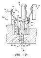
FIG. 7 is a side view of a jig aligned in a hole defined in a spot face according to one embodiment of the present disclosure; -
FIG. 8 is a side view of a jig aligned in a hole defined in a spot face and with bushings engaged therein according to one embodiment of the present disclosure; and -
FIG. 9 is a side view of a jig aligned in a hole defined in a spot face after machining of installation holes according to one embodiment of the present disclosure; - Reference now will be made in detail to embodiments of the invention, one or more examples of which are illustrated in the drawings. Each example is provided by way of explanation of the invention, not limitation of the invention. In fact, it will be apparent to those skilled in the art that various modifications and variations can be made in the present invention without departing from the scope or spirit of the invention. For instance, features illustrated or described as part of one embodiment can be used with another embodiment to yield a still further embodiment. Thus, it is intended that the present invention covers such modifications and variations as come within the scope of the appended claims and their equivalents.
-
FIG. 1 is a schematic diagram of aturbine system 10. Thesystem 10 may include acompressor 12,combustor 14, andturbine 16. Further, thesystem 10 may include a plurality ofcompressors 12,combustors 14, andturbines 16. Thecompressor 12 andturbine 16 may be coupled by ashaft 18. Theshaft 18 may be a single shaft or a plurality of shaft segments coupled together to formshaft 18. It should be understood that the turbine system according to the present disclosure may be a gas turbine system, a steam turbine system, or any other suitable turbine system. -
FIGS. 2 and 3 illustrate one embodiment of acasing 30. Thecasing 30 is located in theturbine system 10, and surrounds various components in a section of theturbine system 10, such as stator and rotor components. For example, thecasing 30 may be for acompressor 12, aturbine 16, or any other suitable section of thesystem 10. As shown inFIG. 3 , a plurality ofspot faces 32 may be machined into or otherwise provided on thecasing 30 during or after manufacturing. Aspot face 32 is a generally planar surface on the exterior of thecasing 30, as shown. Typically, spot faces 32 in various locations on thecasing 30 that may be utilized before, during, or after operation of the system for various purposes, such as testing of thesystem 10. In many such cases, various modifications are made to thecasing 30 on one or more of the spot faces 32. Further, many spot faces 32 may includeholes 34 defined therein to facilitate such modification. Each hole may have an inner width ordiameter 36, and in exemplary embodiments may have a threadedinner wall 38. Theholes 34 are typically plugged during operation of thesystem 10, but may be unplugged as required for modification of aspot face 32. - One purpose requiring modification of a
spot face 32 is the use of various probes to conduct various tests on thesystem 10. For example, clearance probes, proximity probes, or any other suitable probes may be utilized in the system to conduct various tests and provide various data regarding the performance of thesystem 10. A probe must typically be precisely placed with respect to thespot face 32 andcasing 30 in order for it to provide accurate, reliable data. - Thus, as shown in
FIGS. 4 through 9 , ajig 50 is provided for modifying acasing 30 in aturbine system 10. In particular, thejig 50 is provided for precisely and accurately modifying aspot face 32 such that a probe can be precisely mounted thereon. Further, thejig 50 according to the present disclosure advantageously allows for in-field modification of thecasing 30. Thus, expensive and time-consuming transportation of thecasing 30 to a facility in order to modify aspot face 32 is avoided. - As shown,
jig 50 includes abody 52 and aprotrusion 54 extending from thebody 52. While thebody 52 illustrated inFIGS. 4 through 9 is cylindrical, it should be understood that thebody 52 may have any suitable shape and size capable of housing the various features discussed herein. Further, the body in exemplary embodiments fits within aspot face 32. -
Protrusion 54 extends from thebody 52. Theprotrusion 54 may be integral with thebody 52 and thus extend therefrom, or may be a separate component from thebody 52 that is fastened thereon. In some embodiments, theprotrusion 54 may be a generallycentral protrusion 54, thus extending from a central location on a surface of thebody 52. Additionally, theprotrusion 54 has an outer width ordiameter 56, and extends alongaxis 58, as shown inFIGS. 6 and7 .Axis 58 in exemplary embodiments is generally perpendicular to a surface of thebody 52 from which the protrusion extends. Further, in exemplary embodiments, theprotrusion 54 has a threadedouter surface 59. - The
protrusion 54 is further configured for engaging thehole 34 defined in thespot face 32 on thecasing 30. For example, thehole 34 may have a certain cross-sectional shape, such as circular, square, rectangular, oval, triangular, or any other suitable polygonal shape, and size. Theprotrusion 54 may have a similar shape and size such that it may fit into thehole 34. In exemplary embodiments, the shape and size of theprotrusion 54 is substantially identical to the shape and size of thehole 34, such that theprotrusion 54 fits relatively snugly within thehole 34. Thus, in exemplary embodiments, the outer width ordiameter 56 of theprotrusion 54, as shown inFIGS. 6 and7 , may be substantially identical to the inner width ordiameter 36 of thehole 34. - Further, in exemplary embodiments as discussed above, the
protrusion 54 andhole 34 are threaded, as shown by threadedinner wall 38 and threadedouter surface 59 inFIGS. 6 and7 . The threadedouter surface 59 ofprotrusion 54 may engage the threadedinner wall 38 of themating hole 34 when theprotrusion 54 is engaged in thehole 34, and engagement of theprotrusion 54 in thehole 34 may involve screwing theprotrusion 54 into thehole 34 to engage the mating threads. - The
jig 50 further includes at least onemachining passage 60. Eachmachining passage 60 is defined in thebody 52. Further, themachining passages 60 may be positioned in an array within thebody 52. Such array may, in some embodiments, peripherally surround theprotrusion 54. Any number ofmachining passages 60 may be included in thejig 50. For example, while in exemplary embodiments threepassages 60 are defined in the body, it should be understood that one, two, four, five, or more passages may alternatively be defined. Further, in some embodiments, thepassages 60 may be approximately equally spaced apart from each other in an array. For example, in embodiments wherein there are threepassages 60, thepassages 60 may be spaced 120° apart. If there are twopassages 60, thepassages 60 may be spaced 180° apart, while if there are fourpassages 60, thepassages 60 may be spaced 90° apart, and so on. - As shown, in some embodiments, the
machining passages 60 are defined parallel to thecentral protrusion 54. For example, themachining passages 60 may extend through thebody 52 parallel toaxis 58 of theprotrusion 54. Alternatively, however, themachining passages 60 may extend at any suitable angle with respect toaxis 58. Further, as shown inFIG. 9 , eachmachining passage 60 may have an inner width ordiameter 62. - The
machining passages 60 are provided injig 50 for machining installation holes 64 into thecasing 30 through aspot face 32. For example, aninstallation hole 64 may be drilled through amachining passage 60 into thecasing 30 and, optionally, tapped. Such machining of aninstallation hole 64 using amachining passage 60 allows for theinstallation hole 64 to be precisely positioned and oriented. After removal of thejig 50, theinstallation hole 64 may be utilized to mount or otherwise install a probe onto thecasing 30. For example, a stud for the probe may be installed within theinstallation hole 64, and the probe installed by attaching to the stud or otherwise securing in place. - To facilitate machining of an
installation hole 64 through amachining passage 60, thejig 50 may include at least onebushing 70. Further, in exemplary embodiments, one ormore bushings 70 may be provided for eachmachining passage 60. Eachbushing 70 is configured to engage amachining passage 60. For example, apassage 60 may have a certain cross-sectional shape, such as circular, square, rectangular, oval, triangular, or any other suitable polygonal shape, and size. Thebushing 70 may have a similar shape and size such that it may fit into apassage 60. In exemplary embodiments, the shape and size of thebushing 70 is substantially identical to the shape and size of thepassage 60, such that thebushing 70 fits relatively snugly within thepassage 60. Thus, in exemplary embodiments, the outer width ordiameter 72 of thebushing 70, as shown inFIG. 9 , may be substantially identical to the inner width ordiameter 62 of apassage 60. - Further, each
bushing 70 defines apassage 74 therethrough, as shown inFIG. 8 . Thepassage 74 has an inner width ordiameter 76. Thepassage 74 is designed for receiving a drill bit or other suitable machining device therethrough for drilling or otherwise machining aninstallation hole 62. Thepassage 74 may thus be optimally sized, with a suitable inner width ordiameter 76, such that the drill bit or other suitable machining device is precisely oriented and aligned therein. - In some embodiments, the
bushings 70 may be coupled to thejig 50. For example, mating bores 80 and 82 may be defined in thebody 52 andbushing 70, respectively. A wire, chain, or othersuitable coupling apparatus 84 may be run through thebores bushing 70 to thejig 50. - As discussed above, machining of an
installation hole 64 may include drilling and tapping thehole 64 through amachining passage 60 defined in the jig. Thebushing 70 may be engaged in themachine passage 60 to drill thehole 64, and then disengaged from themachine passage 60 to tap thehole 64. Alternatively, however, abushing 70 ormultiple bushings 70, such asbushings 70 having variousinner diameters 76, may be utilized to drill and tap thehole 64, or thehole 64 may be drilled and tapped without the use of anybushing 70. - As shown in
FIGS. 4 through 9 , thejig 50 further includes at least onealignment feature 90. Eachalignment feature 90 is configured on thebody 52. For example, in exemplary embodiments, analignment feature 90 may include analignment passage 92 defined in thebody 52 and analignment pin 94 associated with thealignment passage 92. Further, thealignment passage 92 may have a threaded inner wall 96 and thealignment pin 94 may have a mating threadedouter surface 98. Thus, thealignment pin 94 may be, for example, a screw or other suitable threaded component. - Each
alignment feature 90 may be provided for aligning thejig 50 with respect to thecasing 30. Thus, when thejig 50 is properly positioned with respect to thecasing 30, such as properly leveled and/or oriented, the alignment features 90 may secure thejig 50 in this position to provide a precise alignment of thejig 50. For example, in embodiments wherein thealignment feature 90 includes analignment passage 92 and associatedalignment pin 94, when thejig 50 is properly positioned, thealignment pin 94 is engaged with thepassage 92 and into contact with thespot face 32. For example, thealignment pin 94 may be screwed into thepassage 92 such that the threads of thepassage 92 andpin 94 are engaged and until thepin 94 contacts thespot face 32. Further, eachpin 94 may be engaged to a specified torque, if desired or required. Engagement of thepins 94 with thespot face 32 may securely align thejig 50. For example, engagement of thepins 94 may tension the engagement between theprotrusion 54 and thehole 34, such as the threaded engagement between the threadedinner wall 38 and the threadedouter surface 59. This tension may securely align thejig 50 with respect to thecasing 30, thus preventing or reducing the risk of movement of thejig 50 with respect to thecasing 30. - It should be understood that while an
exemplary alignment feature 90 according to the present disclosure includes analignment passage 92 andalignment pin 94, any suitable component for aligning thejig 50 may further be considered an alignment feature within the scope and spirit of the present disclosure. - The alignment features 90 may be positioned in an array about or within the
body 52. Such array may, in some embodiments, peripherally surround theprotrusion 54. Any number of alignment features 90 may be included in thejig 50. For example, while in exemplary embodiments three alignment features 90 are defined in the body, it should be understood that one, two, four, five, or more alignment features 90 may alternatively be defined. Further, in some embodiments, the alignment features 90 may be approximately equally spaced apart from each other in an array. For example, in embodiments wherein there are three alignment features 90, the alignment features 90 may be spaced 120° apart. If there are two alignment features 90, the alignment features 90 may be spaced 180° apart, while if there are four alignment features 90, the alignment features 90 may be spaced 90° apart, and so on. - As shown, in some embodiments, the alignment features 90 are defined parallel to the
central protrusion 54. For example, the alignment features 90 may extend through thebody 52 parallel toaxis 58 of theprotrusion 54. Alternatively, however, the alignment features 90 may extend at any suitable angle with respect toaxis 58. - As shown in
FIGS. 4 and 5 , in some embodiments, thejig 50 may further include at least oneorientation feature 100. Theorientation feature 100 may be provided for orienting thejig 50 with respect to thecasing 30. For example, as shown, theorientation feature 100 may be an arrow. The arrow may be drawn on, machined into, or otherwise provided on thejig 50. As shown, the arrow points in the general direction of twomachining passages 60 and away from athird machining passage 60, and thus is provided for orienting thejig 50 with regard to themachining passages 60 and/or thecasing 30. In other embodiments, theorientation feature 100 may be provided for any suitable orientation of thejig 50 with regard to any feature of thejig 50, and may have any suitable shape or size. - The
orientation feature 100 may, in exemplary embodiments, orient thejig 50 with respect to various features, such as hooks or other protrusions, which are inside thecasing 30 and thus not visible from exterior to thecasing 30. For example, it may be desirable for the installation holes 64 to have a certain orientation with respect to such various non-visible features. Theorientation feature 100 may indicate a desired orientation with respect to these features, such that the installation holes 64 that result from use of thejig 50 have that desirable orientation and location. - In some embodiments, as shown in
FIGS. 4 through 9 , thejig 50 may further comprise at least oneleveling feature 110. The levelingfeature 110 may be provided for leveling thejig 50. For example, in exemplary embodiments as shown, the levelingfeature 110 may be a channel defined in a surface, such as an upper surface, of thejig 50. The channel may allow for precise placement of a suitable leveling device (not shown), to evaluate and level thejig 50. Alternatively, however, the levelingfeature 110 may be any suitable leveling device or apparatus. - The present disclosure is further directed to a method for modifying a
casing 30 in aturbine system 10. The method may include, for example, engaging ajig 50 with ahole 34 defined in aspot face 32 on thecasing 30, as discussed above. The method may further include aligning thejig 50 with respect to thecasing 30 and machining at least oneinstallation hole 64 into thecasing 30 through thespot face 32, as discussed above. In some embodiments, the method may further include orienting thejig 50 with respect to thecasing 30 and/or leveling thejig 50, as discussed above. - Thus, the present disclosure provides a
jig 50 and a method for modifying acasing 30 that are precise, accurate, and consistent. Further, the present jig and method may advantageously allow for in-field modification of acasing 30, thus reducing the time and expense associated with such modification. - This written description uses examples to disclose the invention, including the best mode, and also to enable any person skilled in the art to practice the invention, including making and using any devices or systems and performing any incorporated methods. The patentable scope of the invention is defined by the claims, and may include other examples that occur to those skilled in the art. Such other examples are intended to be within the scope of the claims if they include structural elements that do not differ from the literal language of the claims, or if they include equivalent structural elements with insubstantial differences from the literal languages of the claims.
Claims (15)
- A method for modifying a casing (30) in a turbine system (10), the method comprising:engaging a jig (50) with a hole (34) defined in a spot face (32) on the casing (30), the jig (50) comprising at least one machining passage (60) and at least one alignment feature (90);aligning the jig (50) with respect to the casing (30); andmachining at least one installation hole (64) into the casing (30) through the spot face (32).
- The method of claim 1, wherein the jig (50) further comprises a protrusion (54) extending from a body (52), and wherein the engaging step comprises engaging the protrusion (54) in the hole (34).
- The method of any of claims 1 or 2, further comprising orienting the jig (50) with respect to the casing (30).
- The method of any of claims 1 to 3, further comprising leveling the jig (50).
- The method of any of claims 1 to 4, wherein the machining step comprises drilling the at least one installation hole (64) and tapping the at least one installation hole (64).
- The method of any of claims 1 to 5, wherein the at least one alignment feature (90) comprises an alignment passage (92) and alignment pin (94), the alignment passage (92) defined in the body (52) and including a threaded inner wall (96) and the alignment pin (94) including a mating threaded outer surface (98).
- A jig (50) for modifying a casing (30) in a turbine system (10), the jig (50) comprising:a body (52);a protrusion (54) extending from the body (54) and configured for engaging a hole (34) defined in a spot face (32) on the casing (30);at least one machining passage (60) defined in the body (52), the machining passage (60) provided for machining the casing (30) therethrough; andat least one alignment feature (90) configured on the body (52), the at least one alignment feature (90) provided for aligning the jig (50) with respect to the casing (30).
- The jig (50) of claim 7, wherein the at least one machining passage (60) is defined parallel to the central protrusion (54).
- The jig (50) of any of claims 7 or 8, further comprising a plurality of machining passages (60).
- The jig (50) of any of claims 7 to 9, further comprising a plurality of alignment features (90).
- The jig (50) of any of claims 7 to 10, wherein the at least one alignment feature (90) comprises an alignment passage (92) and alignment pin (94), the alignment passage (92) defined in the body (52) and including a threaded inner wall (96) and the alignment pin (94) including a mating threaded outer surface (98).
- The jig (50) of claim 11, wherein the alignment passage (92) is defined in the body (52) parallel to the machining passage (60).
- The jig (50) of any of claims 7 to 12, further comprising at least one bushing (70) configured to engage the at least one machining passage (60).
- The jig (50) of any of claims 7 to 13, further comprising at least one orientation feature (100) for orienting the jig (50) with respect to the casing (30).
- The jig (50) of any of claims 7 to 14, further comprising at least one leveling feature (110) for leveling the jig (50).
Applications Claiming Priority (1)
| Application Number | Priority Date | Filing Date | Title |
|---|---|---|---|
| US13/197,190 US9044812B2 (en) | 2011-08-03 | 2011-08-03 | Jig and method for modifying casing in turbine system |
Publications (2)
| Publication Number | Publication Date |
|---|---|
| EP2554308A1 true EP2554308A1 (en) | 2013-02-06 |
| EP2554308B1 EP2554308B1 (en) | 2016-11-30 |
Family
ID=46639357
Family Applications (1)
| Application Number | Title | Priority Date | Filing Date |
|---|---|---|---|
| EP12178545.5A Not-in-force EP2554308B1 (en) | 2011-08-03 | 2012-07-30 | Jig and method for modifying a casing in a turbine system |
Country Status (3)
| Country | Link |
|---|---|
| US (1) | US9044812B2 (en) |
| EP (1) | EP2554308B1 (en) |
| CN (1) | CN102909411B (en) |
Families Citing this family (1)
| Publication number | Priority date | Publication date | Assignee | Title |
|---|---|---|---|---|
| CN117620245A (en) * | 2023-11-30 | 2024-03-01 | 中船重工中南装备有限责任公司 | A method for processing the inner step end hole with an angular positional relationship with the outer groove |
Citations (5)
| Publication number | Priority date | Publication date | Assignee | Title |
|---|---|---|---|---|
| US2466023A (en) * | 1945-08-11 | 1949-04-05 | Francis J Griffin | Drill jig |
| GB2024674A (en) * | 1978-05-13 | 1980-01-16 | Plas Plugs Ltd | Drilling pattern jig |
| DE19921215A1 (en) * | 1999-05-07 | 2000-11-09 | Schaeffler Waelzlager Ohg | Making guide for cam follower used in internal combustion engine, using auxiliary part covering axial cavity for rotation preventing fitting |
| DE202007011551U1 (en) * | 2007-08-17 | 2007-10-25 | Klann-Spezial-Werkzeugbau-Gmbh | Centering device for aligning tools for machining bores on cylinder heads |
| DE202008003936U1 (en) * | 2008-03-20 | 2008-05-21 | Klann-Spezial-Werkzeugbau-Gmbh | Device for centering tools for machining bores |
Family Cites Families (46)
| Publication number | Priority date | Publication date | Assignee | Title |
|---|---|---|---|---|
| US1782284A (en) * | 1928-12-03 | 1930-11-18 | Betancourt Miguel | Bit gauge and positioning or leveling attachment |
| US2670639A (en) * | 1951-04-09 | 1954-03-02 | Flowers | Broken spark plug remover |
| US2825143A (en) * | 1954-02-12 | 1958-03-04 | Western Electric Co | Template centering jig |
| US2996936A (en) * | 1958-10-02 | 1961-08-22 | Herman T Blaise | Drill jig |
| DE1220696B (en) | 1964-01-31 | 1966-07-07 | Wenczler & Heidenhain | Straight line |
| US3363488A (en) | 1965-09-23 | 1968-01-16 | Edmund R. Thau | Alignment jig for removing studs from truck hubs |
| US3517567A (en) | 1969-01-23 | 1970-06-30 | Avco Corp | Gear support and alignment guide |
| US3603039A (en) | 1969-06-03 | 1971-09-07 | Fmc Corp | Method of and apparatus for machining articles |
| US3635571A (en) | 1970-01-26 | 1972-01-18 | Tool Research & Engineering Co | Boring jig |
| US3661490A (en) * | 1970-01-29 | 1972-05-09 | Trueblood Inc | Injection molding machine |
| US3680193A (en) | 1970-05-25 | 1972-08-01 | Litton Systems Inc | A frame for accurately positioning and mounting electrical connectors |
| DE7119369U (en) | 1971-05-18 | 1972-10-26 | Praemeta G Baumann & Co | DRILLING DEVICE FOR ANCHORING HINGE STRAPS AND D |
| US3764204A (en) | 1971-11-19 | 1973-10-09 | K Line Ind Inc | Valve guide boring fixture |
| US4093394A (en) | 1977-07-05 | 1978-06-06 | Arthur Adams | Dowel hole-boring jig |
| US4153384A (en) | 1977-12-05 | 1979-05-08 | Ike Isaken | Dowel hole boring guide |
| US4248554A (en) | 1979-10-01 | 1981-02-03 | Engineered Products Security Corporation | Door boring jig system |
| US4306823A (en) | 1979-11-23 | 1981-12-22 | Nashlund John E | Boring and routing jig for cylindrical door knob assemblies and the like |
| US4445277A (en) | 1982-10-29 | 1984-05-01 | John Keefe | Universal programmable lock installation device |
| US4865496A (en) | 1988-09-19 | 1989-09-12 | Challis Stairways, Inc. | Boring jig apparatus |
| US5209614A (en) * | 1989-03-21 | 1993-05-11 | Kawneer Company | Template positioning jig |
| US5046901A (en) | 1990-04-16 | 1991-09-10 | Richard Taylor | Flush bolt boring jig |
| US5158406A (en) | 1991-04-02 | 1992-10-27 | Thomas Ulinskas | Boring guide fixture |
| CA2098081A1 (en) | 1992-08-13 | 1994-02-14 | Terry L. Dietz | Alignment guide and method |
| US5309662A (en) | 1992-12-16 | 1994-05-10 | Saco Defense Inc. | Alignment guide |
| US5423156A (en) | 1993-08-23 | 1995-06-13 | Nellessen, Jr.; Peter | Sheathing strap and alignment guide |
| USD356271S (en) | 1993-11-16 | 1995-03-14 | Adamik Michael J | Combination template and boring jig |
| US5800099A (en) * | 1996-01-16 | 1998-09-01 | Cooper; Michael S. | Hole saw guide clamp system |
| US5785569A (en) | 1996-03-25 | 1998-07-28 | Micron Technology, Inc. | Method for manufacturing hollow spacers |
| US5775036A (en) | 1996-04-15 | 1998-07-07 | Stanley, Sr.; Jesse M. | Alignment of objects |
| CA2210442C (en) | 1996-07-16 | 2004-05-04 | Bauer Spezialtiefbau Gmbh | A cutter head, boring jig and device and process for sea bottom boring |
| US5987767A (en) | 1997-07-21 | 1999-11-23 | Roddie; Granville | Alignment jig |
| US5915891A (en) * | 1998-02-17 | 1999-06-29 | Fridman; Yevgeny Z. | Drill guide and method for installing a door lock |
| US6109839A (en) | 1998-06-12 | 2000-08-29 | Thomas; Michael | Combination precision drill guide and replacement part |
| US6659695B2 (en) * | 2000-05-02 | 2003-12-09 | Joon Park | Woodworking dowel master jig |
| US6398465B1 (en) | 2000-09-07 | 2002-06-04 | Emhart Llc | Installation jig for locksets |
| US6466179B1 (en) | 2001-03-20 | 2002-10-15 | Netune Communications, Inc. | Alignment jig assembly |
| US7039715B2 (en) | 2002-05-21 | 2006-05-02 | Microsoft Corporation | Methods and systems for a receiver to allocate bandwidth among incoming communications flows |
| DE602005014018D1 (en) | 2004-04-20 | 2009-05-28 | Finsbury Dev Ltd | alignment guide |
| US20060210367A1 (en) | 2005-03-18 | 2006-09-21 | Hsu Hsiu-Kwei Liu | Wood boring operation aid |
| USD546212S1 (en) | 2006-03-28 | 2007-07-10 | Rooney Bruce P | Tapping guide |
| JP4288519B2 (en) | 2006-09-13 | 2009-07-01 | セイコーエプソン株式会社 | Alignment apparatus and alignment method |
| JP4207074B2 (en) | 2006-09-14 | 2009-01-14 | セイコーエプソン株式会社 | Alignment apparatus and alignment method |
| ATE528792T1 (en) | 2007-12-24 | 2011-10-15 | Ismeca Semiconductor Holding | METHOD AND DEVICE FOR ALIGNING COMPONENTS |
| US8137036B2 (en) * | 2007-12-28 | 2012-03-20 | Sewer Tap Inc. | Coring tool alignment system |
| WO2010085573A1 (en) | 2009-01-21 | 2010-07-29 | Innerspace, Inc. | Burr hole drill alignment guide |
| GB0907650D0 (en) | 2009-05-05 | 2009-07-22 | Depuy Int Ltd | Alignment guide |
-
2011
- 2011-08-03 US US13/197,190 patent/US9044812B2/en active Active
-
2012
- 2012-07-30 EP EP12178545.5A patent/EP2554308B1/en not_active Not-in-force
- 2012-08-03 CN CN201210274473.1A patent/CN102909411B/en active Active
Patent Citations (5)
| Publication number | Priority date | Publication date | Assignee | Title |
|---|---|---|---|---|
| US2466023A (en) * | 1945-08-11 | 1949-04-05 | Francis J Griffin | Drill jig |
| GB2024674A (en) * | 1978-05-13 | 1980-01-16 | Plas Plugs Ltd | Drilling pattern jig |
| DE19921215A1 (en) * | 1999-05-07 | 2000-11-09 | Schaeffler Waelzlager Ohg | Making guide for cam follower used in internal combustion engine, using auxiliary part covering axial cavity for rotation preventing fitting |
| DE202007011551U1 (en) * | 2007-08-17 | 2007-10-25 | Klann-Spezial-Werkzeugbau-Gmbh | Centering device for aligning tools for machining bores on cylinder heads |
| DE202008003936U1 (en) * | 2008-03-20 | 2008-05-21 | Klann-Spezial-Werkzeugbau-Gmbh | Device for centering tools for machining bores |
Also Published As
| Publication number | Publication date |
|---|---|
| US9044812B2 (en) | 2015-06-02 |
| CN102909411B (en) | 2017-06-13 |
| EP2554308B1 (en) | 2016-11-30 |
| CN102909411A (en) | 2013-02-06 |
| US20130034397A1 (en) | 2013-02-07 |
Similar Documents
| Publication | Publication Date | Title |
|---|---|---|
| EP2439008B1 (en) | Method and apparatus for machining a shroud block | |
| CN110614504A (en) | Centering tool and method for steam turbine and generator rotor coupling | |
| CN113447272B (en) | Aeroengine blade subassembly anchor clamps | |
| US10487693B2 (en) | Instrumentation boss for fan containment case | |
| CN110186686A (en) | A kind of borescope plug component | |
| EP3281054A1 (en) | Systems and methods for attaching a borescope flexible probe or a guide tube to a component of a gas turbine engine | |
| CN103580375A (en) | Wind turbine generator and maintenance of its main bearing | |
| CN205422945U (en) | System for a rotatable pencil for laying turbomachinery | |
| US20150078892A1 (en) | Eccentric coupling device and method for coupling mating casings in a turbomachine | |
| US20150125267A1 (en) | Standardized gas turbine inspection port system | |
| US9044812B2 (en) | Jig and method for modifying casing in turbine system | |
| US10760449B2 (en) | Fixing device, rotary machine, manufacturing method of rotary machine, assembling method of rotary machine, and disassembling method of rotary machine | |
| CN211305463U (en) | Centering tool for steam turbine and generator rotor coupling | |
| US6648540B2 (en) | Rabbet plate for coupling rotors | |
| CN216956400U (en) | Testing tool for detecting whether iron nut is neglected to be installed on remote controller shell | |
| CN207564365U (en) | Coupling Alignment Tooling and Coupling Alignment System | |
| US20120171037A1 (en) | Probe assembly for use in turbine engines and method of assembling same | |
| CN218905068U (en) | Fixing jig for test needle | |
| CN222308739U (en) | Dynamic balance plug screw mounting device for gas turbine rotor | |
| CN215867026U (en) | Auxiliary inspection device for magnetic poles in rotor magnetic pole assembling process | |
| CN223172405U (en) | Sealing plug installation and removal tool | |
| KR100614079B1 (en) | Rotary shaft alignment mechanism used in coupling installation and its use method | |
| CN208294892U (en) | A kind of locking device | |
| EP2912283B1 (en) | An alignment device for a turbomachine component and turbomachine including such device | |
| KR20140044024A (en) | Equipment for testing assemblability of vane segment |
Legal Events
| Date | Code | Title | Description |
|---|---|---|---|
| PUAI | Public reference made under article 153(3) epc to a published international application that has entered the european phase |
Free format text: ORIGINAL CODE: 0009012 |
|
| AK | Designated contracting states |
Kind code of ref document: A1 Designated state(s): AL AT BE BG CH CY CZ DE DK EE ES FI FR GB GR HR HU IE IS IT LI LT LU LV MC MK MT NL NO PL PT RO RS SE SI SK SM TR |
|
| AX | Request for extension of the european patent |
Extension state: BA ME |
|
| 17P | Request for examination filed |
Effective date: 20130806 |
|
| RBV | Designated contracting states (corrected) |
Designated state(s): AL AT BE BG CH CY CZ DE DK EE ES FI FR GB GR HR HU IE IS IT LI LT LU LV MC MK MT NL NO PL PT RO RS SE SI SK SM TR |
|
| GRAP | Despatch of communication of intention to grant a patent |
Free format text: ORIGINAL CODE: EPIDOSNIGR1 |
|
| INTG | Intention to grant announced |
Effective date: 20160830 |
|
| GRAS | Grant fee paid |
Free format text: ORIGINAL CODE: EPIDOSNIGR3 |
|
| GRAA | (expected) grant |
Free format text: ORIGINAL CODE: 0009210 |
|
| AK | Designated contracting states |
Kind code of ref document: B1 Designated state(s): AL AT BE BG CH CY CZ DE DK EE ES FI FR GB GR HR HU IE IS IT LI LT LU LV MC MK MT NL NO PL PT RO RS SE SI SK SM TR |
|
| REG | Reference to a national code |
Ref country code: CH Ref legal event code: EP Ref country code: GB Ref legal event code: FG4D |
|
| REG | Reference to a national code |
Ref country code: AT Ref legal event code: REF Ref document number: 849328 Country of ref document: AT Kind code of ref document: T Effective date: 20161215 |
|
| REG | Reference to a national code |
Ref country code: IE Ref legal event code: FG4D |
|
| REG | Reference to a national code |
Ref country code: DE Ref legal event code: R096 Ref document number: 602012025951 Country of ref document: DE |
|
| PG25 | Lapsed in a contracting state [announced via postgrant information from national office to epo] |
Ref country code: LV Free format text: LAPSE BECAUSE OF FAILURE TO SUBMIT A TRANSLATION OF THE DESCRIPTION OR TO PAY THE FEE WITHIN THE PRESCRIBED TIME-LIMIT Effective date: 20161130 |
|
| REG | Reference to a national code |
Ref country code: LT Ref legal event code: MG4D |
|
| REG | Reference to a national code |
Ref country code: NL Ref legal event code: MP Effective date: 20161130 |
|
| REG | Reference to a national code |
Ref country code: AT Ref legal event code: MK05 Ref document number: 849328 Country of ref document: AT Kind code of ref document: T Effective date: 20161130 |
|
| PG25 | Lapsed in a contracting state [announced via postgrant information from national office to epo] |
Ref country code: SE Free format text: LAPSE BECAUSE OF FAILURE TO SUBMIT A TRANSLATION OF THE DESCRIPTION OR TO PAY THE FEE WITHIN THE PRESCRIBED TIME-LIMIT Effective date: 20161130 Ref country code: LT Free format text: LAPSE BECAUSE OF FAILURE TO SUBMIT A TRANSLATION OF THE DESCRIPTION OR TO PAY THE FEE WITHIN THE PRESCRIBED TIME-LIMIT Effective date: 20161130 Ref country code: GR Free format text: LAPSE BECAUSE OF FAILURE TO SUBMIT A TRANSLATION OF THE DESCRIPTION OR TO PAY THE FEE WITHIN THE PRESCRIBED TIME-LIMIT Effective date: 20170301 Ref country code: NO Free format text: LAPSE BECAUSE OF FAILURE TO SUBMIT A TRANSLATION OF THE DESCRIPTION OR TO PAY THE FEE WITHIN THE PRESCRIBED TIME-LIMIT Effective date: 20170228 |
|
| PG25 | Lapsed in a contracting state [announced via postgrant information from national office to epo] |
Ref country code: RS Free format text: LAPSE BECAUSE OF FAILURE TO SUBMIT A TRANSLATION OF THE DESCRIPTION OR TO PAY THE FEE WITHIN THE PRESCRIBED TIME-LIMIT Effective date: 20161130 Ref country code: FI Free format text: LAPSE BECAUSE OF FAILURE TO SUBMIT A TRANSLATION OF THE DESCRIPTION OR TO PAY THE FEE WITHIN THE PRESCRIBED TIME-LIMIT Effective date: 20161130 Ref country code: PL Free format text: LAPSE BECAUSE OF FAILURE TO SUBMIT A TRANSLATION OF THE DESCRIPTION OR TO PAY THE FEE WITHIN THE PRESCRIBED TIME-LIMIT Effective date: 20161130 Ref country code: HR Free format text: LAPSE BECAUSE OF FAILURE TO SUBMIT A TRANSLATION OF THE DESCRIPTION OR TO PAY THE FEE WITHIN THE PRESCRIBED TIME-LIMIT Effective date: 20161130 Ref country code: ES Free format text: LAPSE BECAUSE OF FAILURE TO SUBMIT A TRANSLATION OF THE DESCRIPTION OR TO PAY THE FEE WITHIN THE PRESCRIBED TIME-LIMIT Effective date: 20161130 Ref country code: AT Free format text: LAPSE BECAUSE OF FAILURE TO SUBMIT A TRANSLATION OF THE DESCRIPTION OR TO PAY THE FEE WITHIN THE PRESCRIBED TIME-LIMIT Effective date: 20161130 Ref country code: PT Free format text: LAPSE BECAUSE OF FAILURE TO SUBMIT A TRANSLATION OF THE DESCRIPTION OR TO PAY THE FEE WITHIN THE PRESCRIBED TIME-LIMIT Effective date: 20170330 |
|
| PG25 | Lapsed in a contracting state [announced via postgrant information from national office to epo] |
Ref country code: NL Free format text: LAPSE BECAUSE OF FAILURE TO SUBMIT A TRANSLATION OF THE DESCRIPTION OR TO PAY THE FEE WITHIN THE PRESCRIBED TIME-LIMIT Effective date: 20161130 |
|
| PG25 | Lapsed in a contracting state [announced via postgrant information from national office to epo] |
Ref country code: SK Free format text: LAPSE BECAUSE OF FAILURE TO SUBMIT A TRANSLATION OF THE DESCRIPTION OR TO PAY THE FEE WITHIN THE PRESCRIBED TIME-LIMIT Effective date: 20161130 Ref country code: DK Free format text: LAPSE BECAUSE OF FAILURE TO SUBMIT A TRANSLATION OF THE DESCRIPTION OR TO PAY THE FEE WITHIN THE PRESCRIBED TIME-LIMIT Effective date: 20161130 Ref country code: CZ Free format text: LAPSE BECAUSE OF FAILURE TO SUBMIT A TRANSLATION OF THE DESCRIPTION OR TO PAY THE FEE WITHIN THE PRESCRIBED TIME-LIMIT Effective date: 20161130 Ref country code: RO Free format text: LAPSE BECAUSE OF FAILURE TO SUBMIT A TRANSLATION OF THE DESCRIPTION OR TO PAY THE FEE WITHIN THE PRESCRIBED TIME-LIMIT Effective date: 20161130 Ref country code: EE Free format text: LAPSE BECAUSE OF FAILURE TO SUBMIT A TRANSLATION OF THE DESCRIPTION OR TO PAY THE FEE WITHIN THE PRESCRIBED TIME-LIMIT Effective date: 20161130 |
|
| PG25 | Lapsed in a contracting state [announced via postgrant information from national office to epo] |
Ref country code: BG Free format text: LAPSE BECAUSE OF FAILURE TO SUBMIT A TRANSLATION OF THE DESCRIPTION OR TO PAY THE FEE WITHIN THE PRESCRIBED TIME-LIMIT Effective date: 20170228 Ref country code: IT Free format text: LAPSE BECAUSE OF FAILURE TO SUBMIT A TRANSLATION OF THE DESCRIPTION OR TO PAY THE FEE WITHIN THE PRESCRIBED TIME-LIMIT Effective date: 20161130 Ref country code: SM Free format text: LAPSE BECAUSE OF FAILURE TO SUBMIT A TRANSLATION OF THE DESCRIPTION OR TO PAY THE FEE WITHIN THE PRESCRIBED TIME-LIMIT Effective date: 20161130 Ref country code: BE Free format text: LAPSE BECAUSE OF FAILURE TO SUBMIT A TRANSLATION OF THE DESCRIPTION OR TO PAY THE FEE WITHIN THE PRESCRIBED TIME-LIMIT Effective date: 20161130 |
|
| REG | Reference to a national code |
Ref country code: DE Ref legal event code: R097 Ref document number: 602012025951 Country of ref document: DE |
|
| PLBE | No opposition filed within time limit |
Free format text: ORIGINAL CODE: 0009261 |
|
| STAA | Information on the status of an ep patent application or granted ep patent |
Free format text: STATUS: NO OPPOSITION FILED WITHIN TIME LIMIT |
|
| 26N | No opposition filed |
Effective date: 20170831 |
|
| PG25 | Lapsed in a contracting state [announced via postgrant information from national office to epo] |
Ref country code: SI Free format text: LAPSE BECAUSE OF FAILURE TO SUBMIT A TRANSLATION OF THE DESCRIPTION OR TO PAY THE FEE WITHIN THE PRESCRIBED TIME-LIMIT Effective date: 20161130 |
|
| REG | Reference to a national code |
Ref country code: DE Ref legal event code: R119 Ref document number: 602012025951 Country of ref document: DE |
|
| REG | Reference to a national code |
Ref country code: CH Ref legal event code: PL |
|
| GBPC | Gb: european patent ceased through non-payment of renewal fee |
Effective date: 20170730 |
|
| REG | Reference to a national code |
Ref country code: FR Ref legal event code: ST Effective date: 20180330 |
|
| PG25 | Lapsed in a contracting state [announced via postgrant information from national office to epo] |
Ref country code: CH Free format text: LAPSE BECAUSE OF NON-PAYMENT OF DUE FEES Effective date: 20170731 Ref country code: LI Free format text: LAPSE BECAUSE OF NON-PAYMENT OF DUE FEES Effective date: 20170731 Ref country code: DE Free format text: LAPSE BECAUSE OF NON-PAYMENT OF DUE FEES Effective date: 20180201 Ref country code: GB Free format text: LAPSE BECAUSE OF NON-PAYMENT OF DUE FEES Effective date: 20170730 |
|
| REG | Reference to a national code |
Ref country code: IE Ref legal event code: MM4A |
|
| PG25 | Lapsed in a contracting state [announced via postgrant information from national office to epo] |
Ref country code: FR Free format text: LAPSE BECAUSE OF NON-PAYMENT OF DUE FEES Effective date: 20170731 |
|
| PG25 | Lapsed in a contracting state [announced via postgrant information from national office to epo] |
Ref country code: LU Free format text: LAPSE BECAUSE OF NON-PAYMENT OF DUE FEES Effective date: 20170730 |
|
| PG25 | Lapsed in a contracting state [announced via postgrant information from national office to epo] |
Ref country code: IE Free format text: LAPSE BECAUSE OF NON-PAYMENT OF DUE FEES Effective date: 20170730 |
|
| PG25 | Lapsed in a contracting state [announced via postgrant information from national office to epo] |
Ref country code: MT Free format text: LAPSE BECAUSE OF NON-PAYMENT OF DUE FEES Effective date: 20170730 |
|
| PG25 | Lapsed in a contracting state [announced via postgrant information from national office to epo] |
Ref country code: MC Free format text: LAPSE BECAUSE OF FAILURE TO SUBMIT A TRANSLATION OF THE DESCRIPTION OR TO PAY THE FEE WITHIN THE PRESCRIBED TIME-LIMIT Effective date: 20161130 Ref country code: HU Free format text: LAPSE BECAUSE OF FAILURE TO SUBMIT A TRANSLATION OF THE DESCRIPTION OR TO PAY THE FEE WITHIN THE PRESCRIBED TIME-LIMIT; INVALID AB INITIO Effective date: 20120730 |
|
| PG25 | Lapsed in a contracting state [announced via postgrant information from national office to epo] |
Ref country code: CY Free format text: LAPSE BECAUSE OF NON-PAYMENT OF DUE FEES Effective date: 20161130 |
|
| PG25 | Lapsed in a contracting state [announced via postgrant information from national office to epo] |
Ref country code: MK Free format text: LAPSE BECAUSE OF FAILURE TO SUBMIT A TRANSLATION OF THE DESCRIPTION OR TO PAY THE FEE WITHIN THE PRESCRIBED TIME-LIMIT Effective date: 20161130 |
|
| PG25 | Lapsed in a contracting state [announced via postgrant information from national office to epo] |
Ref country code: TR Free format text: LAPSE BECAUSE OF FAILURE TO SUBMIT A TRANSLATION OF THE DESCRIPTION OR TO PAY THE FEE WITHIN THE PRESCRIBED TIME-LIMIT Effective date: 20161130 |
|
| PG25 | Lapsed in a contracting state [announced via postgrant information from national office to epo] |
Ref country code: AL Free format text: LAPSE BECAUSE OF FAILURE TO SUBMIT A TRANSLATION OF THE DESCRIPTION OR TO PAY THE FEE WITHIN THE PRESCRIBED TIME-LIMIT Effective date: 20161130 Ref country code: IS Free format text: LAPSE BECAUSE OF FAILURE TO SUBMIT A TRANSLATION OF THE DESCRIPTION OR TO PAY THE FEE WITHIN THE PRESCRIBED TIME-LIMIT Effective date: 20170330 |