EP2553786B1 - Verfahren zur steuerungsübertragung zwischen vorrichtungen in einem unterstationssystem und vorrichtung dafür - Google Patents
Verfahren zur steuerungsübertragung zwischen vorrichtungen in einem unterstationssystem und vorrichtung dafür Download PDFInfo
- Publication number
- EP2553786B1 EP2553786B1 EP10734814.6A EP10734814A EP2553786B1 EP 2553786 B1 EP2553786 B1 EP 2553786B1 EP 10734814 A EP10734814 A EP 10734814A EP 2553786 B1 EP2553786 B1 EP 2553786B1
- Authority
- EP
- European Patent Office
- Prior art keywords
- devices
- substation
- hot
- transfer
- control
- Prior art date
- Legal status (The legal status is an assumption and is not a legal conclusion. Google has not performed a legal analysis and makes no representation as to the accuracy of the status listed.)
- Active
Links
Images

Classifications
-
- H—ELECTRICITY
- H02—GENERATION; CONVERSION OR DISTRIBUTION OF ELECTRIC POWER
- H02H—EMERGENCY PROTECTIVE CIRCUIT ARRANGEMENTS
- H02H7/00—Emergency protective circuit arrangements specially adapted for specific types of electric machines or apparatus or for sectionalised protection of cable or line systems, and effecting automatic switching in the event of an undesired change from normal working conditions
- H02H7/26—Sectionalised protection of cable or line systems, e.g. for disconnecting a section on which a short-circuit, earth fault, or arc discharge has occured
- H02H7/261—Sectionalised protection of cable or line systems, e.g. for disconnecting a section on which a short-circuit, earth fault, or arc discharge has occured involving signal transmission between at least two stations
-
- H—ELECTRICITY
- H02—GENERATION; CONVERSION OR DISTRIBUTION OF ELECTRIC POWER
- H02H—EMERGENCY PROTECTIVE CIRCUIT ARRANGEMENTS
- H02H1/00—Details of emergency protective circuit arrangements
- H02H1/0061—Details of emergency protective circuit arrangements concerning transmission of signals
-
- H—ELECTRICITY
- H02—GENERATION; CONVERSION OR DISTRIBUTION OF ELECTRIC POWER
- H02H—EMERGENCY PROTECTIVE CIRCUIT ARRANGEMENTS
- H02H3/00—Emergency protective circuit arrangements for automatic disconnection directly responsive to an undesired change from normal electric working condition with or without subsequent reconnection ; integrated protection
- H02H3/02—Details
- H02H3/05—Details with means for increasing reliability, e.g. redundancy arrangements
-
- Y—GENERAL TAGGING OF NEW TECHNOLOGICAL DEVELOPMENTS; GENERAL TAGGING OF CROSS-SECTIONAL TECHNOLOGIES SPANNING OVER SEVERAL SECTIONS OF THE IPC; TECHNICAL SUBJECTS COVERED BY FORMER USPC CROSS-REFERENCE ART COLLECTIONS [XRACs] AND DIGESTS
- Y02—TECHNOLOGIES OR APPLICATIONS FOR MITIGATION OR ADAPTATION AGAINST CLIMATE CHANGE
- Y02E—REDUCTION OF GREENHOUSE GAS [GHG] EMISSIONS, RELATED TO ENERGY GENERATION, TRANSMISSION OR DISTRIBUTION
- Y02E60/00—Enabling technologies; Technologies with a potential or indirect contribution to GHG emissions mitigation
-
- Y—GENERAL TAGGING OF NEW TECHNOLOGICAL DEVELOPMENTS; GENERAL TAGGING OF CROSS-SECTIONAL TECHNOLOGIES SPANNING OVER SEVERAL SECTIONS OF THE IPC; TECHNICAL SUBJECTS COVERED BY FORMER USPC CROSS-REFERENCE ART COLLECTIONS [XRACs] AND DIGESTS
- Y04—INFORMATION OR COMMUNICATION TECHNOLOGIES HAVING AN IMPACT ON OTHER TECHNOLOGY AREAS
- Y04S—SYSTEMS INTEGRATING TECHNOLOGIES RELATED TO POWER NETWORK OPERATION, COMMUNICATION OR INFORMATION TECHNOLOGIES FOR IMPROVING THE ELECTRICAL POWER GENERATION, TRANSMISSION, DISTRIBUTION, MANAGEMENT OR USAGE, i.e. SMART GRIDS
- Y04S10/00—Systems supporting electrical power generation, transmission or distribution
- Y04S10/16—Electric power substations
Definitions
- the invention relates generally to the field of Substation Automation, and more specifically to the configuration and operation of intelligent electronic devices deployed in the substations.
- An electrical or power substation involves electricity transmission and distribution systems where voltage is transformed from high to low or the reverse using transformers. Electric power may flow through several substations between generating plant and consumer, and in the process being transformed through many voltage levels in several steps.
- Appropriate equipments are selected for these functions depending on whether the substation is a transmission, sub-transmission or distribution substation. These equipments could include transformers, reactors, capacitor banks, circuit breakers, disconnector switches etcetera.
- Substation Automation involves protection, control, monitoring and metering functions of the above mentioned equipment and derives reliable information for efficient functioning of the substation.
- IEDs Intelligent Electronic Devices
- SA Substation Automation
- the IEDs are microprocessor-based controllers of power system equipment, such as circuit breakers, transformers, and capacitor banks.
- the IEDs receive data from sensors and power equipment, and can issue control commands, such as tripping circuit breakers if they sense voltage, current, or frequency anomalies, or raise/lower voltage levels in order to maintain the desired level.
- control commands such as tripping circuit breakers if they sense voltage, current, or frequency anomalies, or raise/lower voltage levels in order to maintain the desired level.
- Common types of IEDs include protective relaying devices, load tap changer controllers, circuit breaker controllers, capacitor bank switches, recloser controllers, voltage regulators, etc. These IEDs are advantageous because, with the available microprocessor technology a single unit can perform several protection, metering, monitoring and control functions concurrently.
- Substation Automation forms an important and complex aspect for maintenance and control of different equipments involved in different processes within the substation.
- the substation communication network is categorized into three layers such as process bus, bay bus, station bus.
- the primary equipments like the transformers, Merging Unit, circuit breakers, isolators and switches reside in the substation switch yard. These devices are connected through the process bus where the control commands, digitized voltage/current information, etc, flow across various layers of the substation communication architecture.
- the secondary devices are the intelligent electronic devices performing the protection, control, metering and monitoring functionalities by communicating with the primary equipments and hosted by the bay bus.
- the station bus connects the operator workstation, engineering workstation, etc, of the substation automation system to the rest of the substation elements, which communicate over the process and bay bus.
- the IEDs in various layers of the substation communication network uses different communication profiles for communicating their data.
- Multiple protocols exist for Substation Automation which include many proprietary protocols with custom communication links.
- interoperation of devices from different vendors is highly desired for simplicity in implementation and use of Substation Automation devices.
- Reference EP 2 159 893 A1 relates to redundancy concepts for substation automation that prevents a single failing intelligent electronic device (IED) from impairing the operation of a bay of a substation.
- IED intelligent electronic device
- IEC61850 International Electrotechnical Commission (IEC) is a standard for communication networks and systems in substation, which advocates interoperability amongst Intelligent Electronic Devices (IEDs) from various manufacturers using common engineering models, data formats and communication protocol. Recent IEDs are designed to support the IEC61850 standard for substation automation by implementing the IEC61850 profiles as per the application requirements, thereby providing interoperability and advanced communications capabilities and these IEDs are termed as IEC61850 compliant IEDs.
- IEC61850 compliant IEDs IEC61850 compliant IEDs.
- IED should be interpreted as IEC61850 compliant IED unless specified otherwise.
- the IEC 61850 standard promotes the Merging Unit (MU) which provides the standard digital interface to both conventional and non-conventional the instrument transformers.
- the MU communicates the digitized voltage/current information using the IEC 61850-9-2 profile across the substation communication network.
- the IEDs in the bay performs its function by utilizing the IEC 61850-9-2 data from MU and coordinating with the other IEDs in the substation automation system.
- Such communications between IEDs involve the status update, executing commands based on the status of IED group, etc., and based on the GOOSE (Generic Object Oriented Substation Event) message format defined by the IEC 61850.
- GOOSE Generic Object Oriented Substation Event
- the substation operator can monitor and control the substation automation system from their operator workstation terminal by communicating with the IEDs in the communication network through the MMS (Manufactures Message Specifications) profile. Since the operator workstation and/or the engineering workstation are located in the control center which is a central point receiving the information from multiple bays, data acquisition from various IEDs are session based and monitoring is less time critical the TCP/IP based MMS profile is preferred in such conditions.
- MMS Manufacturing Message Specifications
- the MMS stack is a heavy weight stack as it must support various control blocks like report, log, etc., and the MMS traffic along with the sampled measured value traffic in the process bus would cause system reliability issues. Moreover the MMS clients can get the required information of the system from the bay level IEDs supporting MMS stack for supervisory and control purpose, which encourages to implement the GOOSE profile than the MMS stack in process bus IEDs. It is to be noted that many standard features in IEC 61850 are defined and well supported for IEDs communicating over the bay bus and not much for applications over the process bus. Thus, there is a need to define method that enable and coordinate mission or/and time critical functions for the IEDs that communicate desirably using GOOSE messages over the process bus.
- the invention describes a method for coordinated transfer of control in a substation system comprising IED or logical devices/servers using GOOSE messages with preconfigured data models with logical nodes containing one or more data objects including private data objects (DO) connected in the substation communication network.
- the method for transfer of control is illustrated for hot-standby device management and for other applications such as logical isolation of merging unit in a substation and load sharing between IEDs.
- the method is particularly relevant for devices that do not have MMS stack.
- the solution addressed by the invention makes the MMS client configuration simpler by enclosing the hot-standby logical devices/servers in a single IED and also the network, IEC 61850 configuration parameters are same for both hot and standby logical devices/server. So the MMS client always sees this pair as a single IED and connects with hot logical node that is made possible by enabling the TCP/IP stack of only the 'current hot' logical device.
- the solution means being a GOOSE message with private DOs
- the hot-standby switchover on demand is enabled within milliseconds compared to the prior-art of enabling standby based on failure of receiving operational GOOSE message, preconfigured for a certain number of retransmission cycles (delay maybe in seconds).
- the coordination message makes the hot-standby logical node aware of each others state thereby solving few typical hot-standby scenarios like the failed hot IED recovering from failure and interfering with the functioning IED.
- a third IED with GOOSE stack can also be used for supervising the hot-standby pair IED through this coordination messages.
- the hot-standby use case and the other uses cases for logical isolation and load sharing involves transfer of control (relieving of control) to another device (the another device is any other substation automation device in the substation communication network).
- the method for transfer of control is described as between a first device and a second device wherein the first and the second devices are from a group of at least two devices connected in the substation communication network and where each of the devices connected in the substation communication are involved in at least one function in a substation system.
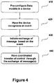
- the method comprises of the following steps:
- the message communication between the first and the second devices includes instructions, device state information, substation state data, substation equipment data and acknowledgments as relevant for the use case function.
- the invention is described with an example of Hot-Standby redundancy mechanism to illustrate the method to enable and coordinate mission and time critical functions for the IEDs that communicate using GOOSE messages over the process bus.
- Other scenarios such as load sharing mechanism between IEDs is described as an example of mission critical function as an embodiment of this invention and an example from a simulation/testing scenario is briefly described to illustrate applicability of the invention for general applications.
- the IEDs in each bay perform different functions and coordinate between them by communicating various data for reliable Substation Automation (SA) system functioning.
- SA Substation Automation
- the current practice in the SAS to increase the reliability of the system is deploying redundant IEDs in various levels.
- the redundancy concepts have evolved by implementing different types of redundancy mechanisms like physical redundancy by deploying more than one IED with same functional principle, functional redundancy by deploying IEDs with different functional principles, communication redundancy by installing redundant communication path between IEDs, etc.,.
- the exemplary way of invoking the standby IED in the hot-standby pair is by triggering the hardwired status signal during an exceptional scenario. For example the watchdog timer triggering the status signal when the hot IEDs is trapped in to an exception.
- Substation Automation System are designed such a way that single point of failure will not cause failure of the entire system.
- Communication redundancy eg mode of communication, communication protocols etc
- source level redundancy eg. Backup power supply, battery backup etc
- physical redundancy for devices and accessories
- Physical device redundancy can be achieved in two ways.
- One way is deploying both the main IED and the backup IED (each with different control block reference, dataset reference, etc.,), which can publish the data on to the same communication network, but this way requires larger bandwidth for the communication network.
- both the main and backup merging unit publishes messages on the same communication bus requiring increased bandwidth for the communication bus.
- Second way to achieve physical device redundancy is by deploying the main IED and backup IEDs, each with different control block reference, dataset reference, etc., in the substation network, but each on a different bus. This way, in turn requires more communication network accessories involving additional switches, buses/cables, etc., to route the traffic from above said main IED and backup IEDs, where both IEDs are publishers. This way of achieving physical redundancy involves lots of network infrastructure that results in high cost solution.
- the subscribing IED need to be capable of handling increased amount of data traffic from main and backup IEDs.
- This need poses stringent design requirements resulting in high cost of the IEDs.
- the main Merging Unit and the backup Merging Unit publishing the data would typically double the network bandwidth requirement, otherwise require dual bus, but in any case the protection relay receiving the SMV (Sampled and Measured Value) data must handle the huge amount of data in relatively less time
- an IED referred here as the "hot” IED is provided along with a backup (standby) IED.
- the backup IED monitors the hot IED assessing if the hot IED is functioning normally (without fault) and does not participate in any external visible operation (silent observer).
- the backup IED takes over the functionality of the hot IED on an event where the hot IED is unable to provide the required service.
- a coordinated Hot & Standby IED concept allows use of one or more IEDs with hardly any increase in design consideration.
- the invention describes a means to achieve such a coordinated concept using GOOSE messages with Private Data Objects (DO).
- DO Data Object
- the IEDs have good computational power and perform various functions including the task of communicating within the system.
- the IEDs in the hot-standby pair exchange the messages for both switching over the role as well as the exchanging various status messages detailing the state of each IED in the hot-standby pair at any moment.
- this involves communication and message processing overhead compared to the conventional way of triggering the hot-standby systems, but serves better where hot-standby switch over time can be slightly higher without affecting the system performance.
- This method is well suited in a scenario where the standby IED is invoked by the detection of operational message failure because this method performs hot-standby switch over much earlier before detecting the failure of operational message.
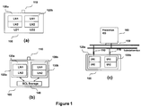
- Figure 1 illustrates an arrangement with a single physical device 100 having one or more Ethernet connectivity 110 but configured to have two logical devices (120a and 120b) where the two logical devices are functionally identical.
- the device 100 is said to be pre-configured for transfer of control for the hot-standby application. It is to be noted that the device 100 may also exists as having only one logical device (120) for enabling other applications (eg logical isolation).
- Pre-configuration includes having one or more data models with one or more logical nodes containing one or more data objects for addressing at least one device deployed in the substation system and connected in the substation bus.
- the logical devices may be implemented on a hypervisor so that these are running on two different virtual platform sharing the common Ethernet connectivity ( Figure 1(a) ).
- the two logical devices communicate with each other through GOOSE for coordinated role change as HOT or Standby.
- Each of the logical devices may have one or more logical nodes (LN) defined as required for the function configured in it.
- the one or more logical node may be mandatory or private or any other logical node created under one or more logical device and the one or more data objects may be private or any other data object created under one or more logical nodes.
- the logical devices (120) have a separate CPU for each logical devices and are place in a single enclosure so that the client sees a single phyical device.
- the logical devices here are shown to have their own Ethernet port for connectivity.
- the logical devices (120) are the servers and shares a common Flash System for SCL (Substation Configuration Language) files such as SCD (Substation Configuration Description), ICD (IED Capability Description) files.
- SCL Substation Configuration Language
- ICD IED Capability Description
- the hot and standby servers are placed in a single enclosure.
- the logical devices (120) are said to be running on two different cores in a multi-core virtualization arrangement depicted in Figure 1(c) .
- the device 100 is also shown as connected to the substation communication network 150 depicted as substation bus having other substation devices 160 (including IEDs, relays etc) connected to the substation bus.
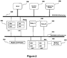
- Figure 2 depicts the substation system having the device 100 connected in the process bus 210 and another device 100 connected to the process bus 210 and the station bus 220.
- the communication network (substation bus) 210 and 220 have other devices (primary electrical equipment 230, primary devices 100, 240, servers 250 and clients 260) connected in the substation bus.
- the SCADA (Supervisory Control and Data Acquistion)/ client configuration is simple because it sees a single IED wherein hot-standby switch over happens internally. This method of functionality take over/handover can be used specifically during a non time critical scenarios such as the hot IED has found some exceptions like battery low, RTC (Real Time Clock) failure, RAM (Random Access Memory) corruption, etc., but still it can communicate with the Standby IED.
- RTC Real Time Clock
- RAM Random Access Memory
- the GOOSE control block reference, dataset reference, application id, GOOSE id in a GOOSE message generated by any of the server in the hot-standby pair will be same except the source MAC address.
- the subscribing IED in the multicast group will have no problem in receiving the operational GOOSE messages from the hot-standby IED.
- the hot-standby functionality switchover may be configured to happen without exchanging any GOOSE message, but just listening to the operational GOOSE messages and detecting the hot IEDs failure if a desired GOOSE message is not received for specified amount of time for example one second for IED with one second background cycle. Additionally, the hot-standby switchover may happen within millisecond incase of hot-standby switchover on demand. Also, the failed hot logical device/server does not interfer with the functioning standby logical device upon coming out of failure by switching over the functionality only when the current logical device/server (either hot or standby) is facing some exceptions. This is achieved by storing the state, health information of hot and standby logical devices/server and exchanging them between hot and standby logical devices. As further addition if needed, a third IED with GOOSE stack can be made to act as a supervisory IED and control the switchover process based on the above said supervisory messages originated by both hot and standby logical devices/server.
- the hot-standby IED combinations may be used also for load sharing use cases/applications with the help of coordinated communication as utilized for the hot-standby switch overs.
- IEDs are designed in a way that a single IED can perform more than one function leading to easy configuration and maintenance, efficient data handling in the network due to the computational power that is available with the IED.
- such enormous power is being available at low cost, therefore enhancing the IEDs for load sharing applications are also considered in this invention.
- the Hot IED may transfer the functionality of waveform recording to the standby IED to get relieved from the overload condition.
- This application of load sharing is enable through exchange of GOOSE message with private data object in the manner similar to Hot-Standby switch overs.
- the GOOSE message with private data objects are used for logical isolation functions particularly for the IEDs for example a Merging Unit IED that has only GOOSE stack and not the MMS stack.
- This feature is particularly important for simulation and testing applications, where, a particular IED (example Merging Unit) are required to be isolated and another device or server may perform testing or simulation in the substation system having the IED (Merging Unit) in an isolated condition.
- logical isolation technique may be used to isolate faulty IED during substation automation maintenance or otherwise during operation of the substation (if the IED is able to publish and subscribe the data).
- the method requires that new private data objects for example ' FncHndOvr' (Functionality Handover), ' HotStandbySprvsn' (Hot standby supervision) are defined and assigned to the IEC 61850 common data class, say for example INC.
- the data objects further have enumerated attributes to send various commands.
- the data object ' FncHndOvr' is defined to further have enumerated attributes such as 'Take over the functionality', 'Give up the functionality', 'Share the load', 'Give back the load', 'none', etc. to send various commands.
- the data object ' HotStandbySprvsn' is further defined to have enumerated attribute to send various status information like 'Default hot-Now hot', 'Default hot- Now standby', 'Default Standby-Now Hot', 'Default Standby-Now Standby', 'Default Hot-Now in load sharing mode', 'Default Standby-Now in load sharing mode', etc.
- the IEDs in the hot-standby pair must have the unique identifier for identifying the GOOSE message carrying command for functionality handover and state of the IED from only its hot-standby pair.
- the data model of the Server/Logical Device are preset in the hot-standby pair with the data object for example 'HotStandbyId '(Hot standby identifier) containing a unique identifier of the Server/Logical Device. This is done in the firmware stage, using configuration file or as per user settings. This information is used by the IED initially to understand which logical device is hot and which is standby.
- This data object is assignable to the IEC 61850 common data class, example INC (Integer Control), is instantiated under any mandatory logical node, example LPHD (Logical node for PHysical Device information).
- a dedicated GOOSE control block with dataset containing the data objects 'FncHndOvr', ' HotStandbySprvsn' , ' HotStandbyId' are defined in the IED and the configuration file.
- a mandatory requirement for this method is that the IED identity like GOOSE control block, dataset references must be same for both the hot and standby Servers/Logical Devices.
- Both the hot and the standby Server/Logical Device need to subscribe the GOOSE messages from each other.
- One is the operational data containing status of various inputs.
- the other message is the supervisory message containing the state of the Server/Logical Devices indicating whether it is at present hot or standby along with commands for hot-standby and/or load sharing functionality.
- the supervisory GOOSE message shall carry the private data objects for example 'FncHndOvr', ' HotStandbySprVsn' with enumerated data attribute as described earlier.
- the transfer of control between the hot and the standby devices may be managed with help of a third device wherein the third device recognizes the event requiring the transfer of control and also coordinates with the hot device and the standby device in the substation system and such management may have the hot device and the standby device of one another.
- the MMS client will initially establish a TCP/IP session with the hot IED (MMS client sees the hot-standby IEDs as a single IED) through which various transactions between SCADA system and IED are made.
- MMS client sees the hot-standby IEDs as a single IED
- the TCP/IP session between the 'default hot' logical device/server and MMS client breaks.
- This problem is addressed by enabling the TCP/IP stack of the standby logical device/server only when the functionality handover scenario starts, till then the standby logical device/server runs the modules, which doesn't require TCP/IP stack for example GOOSE.
- the network parameters for both hot and standby logical device/server must be same and the 'default hot' logical device/server should disable the TCP/IP stack when it hands over the functionality.
- the MMS client in this case will not be aware of this hot-standby functionality handover between hot and standby logical devices/servers. So break in TCP/IP session due to hot-standby switchover will be known to the MMS client when it receives the error response for its send/receive requests.
- an IED implementing MMS stack can also receive be programmed for hot-standby use case by having the IED recieve a command from MMS client to switch from hot to standby or vice versa.
- the type of functional constraint for the data attributes of 'FncHndOvr' data object needs ST (Status) and also desirably CO (control) for transacting message between client and server.
- ST Status
- CO control
- the GOOSE control block is configured such that the IED upon receiving the switch over command should generate the GOOSE message as described in earlier paragraphs.
- GOOSE is an exemplary protocol/profile used to explain the invention. Any other protocol irrespective of the communication medium (wired or wireless) can also be used that has a means to communicate periodically the process data or field data or any status data related to the devices in the system. The communication may happen with or with acknowledgements involved in the steps of coordinated transfer of control.
- the data model is any information model and is not restricted to the IEC 61850 data model and the logical nodes is any specific function related to the application system or use and not restricted to IEC 61850 logical nodes.
- the private data object referred in the invention is any data type that is capable of storing or handling information and is not restricted to IEC 61850 private data object.
Landscapes
- Data Exchanges In Wide-Area Networks (AREA)
- Hardware Redundancy (AREA)
- Remote Monitoring And Control Of Power-Distribution Networks (AREA)
- Computer And Data Communications (AREA)
Claims (14)
- Verfahren zur Steuerungsübertragung zwischen einer ersten Vorrichtung (120) und einer zweiten Vorrichtung, wobei die erste und die zweite Vorrichtung aus einer Gruppe von mindestens zwei in dem Unterstationskommunikationsnetzwerk (210, 220) verbundenen Vorrichtungen stammen und wobei jede der in der Unterstationskommunikation verbundenen Vorrichtungen an mindestens einer Funktion in einem Unterstationssystem beteiligt ist, wobei das Verfahren umfasst:a. Man hat ein oder mehrerer Datenmodelle mit einem oder mehreren logischen Knoten (LN), die ein oder mehrere Datenobjekte enthalten, in der ersten Vorrichtung (100) für die Steuerungsübertragung vorkonfiguriert;b. Man hat ein Ereignis, das eine Steuerungsübertragung von der ersten Vorrichtung (100) erfordert, in dem Unterstationssystem identifiziert;c. Man hat mindestens eine Nachrichtenkommunikation, die eine oder mehrere vorkonfigurierte Datenmodelle verwendet, zwischen der ersten Vorrichtung (100) und der zweiten Vorrichtung ausgetauscht, wobei die mindestens eine Nachrichtenkommunikation basierend auf dem Ereignis initiiert wird, das in dem Unterstationssystem erkannt wird; undd. Freigeben der ersten Vorrichtung (120) von der mindestens einen Funktion, indem eine koordinierte Steuerungsübertragung basierend auf der mindestens einen Nachrichteninteraktion mit der ersten Vorrichtung (120) erfolgt.
- Verfahren nach Anspruch 1, wobei die durch das Unterstationsnetzwerk (210, 220) verbundenen Vorrichtungen Vorrichtungen wie IEDs, Merging Unit, Server oder Clients im Unterstationssystem einschließen und logische oder virtualisierte Versionen dieser Vorrichtungen oder eines beliebigen Teils dieser Vorrichtungen einschließen.
- Verfahren nach Anspruch 1, wobei das Ereignis, das in dem Unterstationssystem erkannt wird, ein Ereignis ist, das aufgrund einer Ausnahmebedingung mit einer beliebigen Vorrichtung in dem Unterstationssystem stattfindet, oder ein Ereignis, das aus einer oder mehreren MMS- oder GOOSE-Nachrichtenanfragen für eine beliebige der Vorrichtungen in dem Unterstationssystem resultiert.
- Verfahren nach Anspruch 1, wobei die koordinierte Steuerungsübertragung basierend auf der mindestens einen Nachrichtenkommunikation unter Verwendung eines oder mehrerer Datenmodelle zur Steuerungsübertragung zwischen einer Hot-Vorrichtung und einer Standby-Vorrichtung dient.
- Verfahren nach Anspruch 4, wobei die koordinierte Steuerungsübertragung basierend auf einer Nachrichtenkommunikation zur Steuerungsübertragung zwischen einer Hot-Vorrichtung und einer Standby-Vorrichtung ferner den Schritt umfasst:a. Selbstidentifizieren der Hot- oder/und Standby-Vorrichtung durch Veröffentlichen mindestens einer Nachrichtenkommunikation in dem Unterstationskommunikationsnetzwerk (210, 220); oder/undb. Veröffentlichen mindestens einer Nachrichtenkommunikation von der Hot- oder/und Standby-Vorrichtung als eine Bestätigung zur Steuerungsübertragung zwischen der Hot- und der Standby-Vorrichtung.
- Verfahren nach Anspruch 1, wobei die koordinierte Steuerungsübertragung basierend auf der mindestens einen Nachrichtenkommunikation zur Steuerungsübertragung mindestens einer Funktionalität von der ersten Vorrichtung (120) dient.
- Verfahren nach Anspruch 1, wobei die erste Vorrichtung (120) eine Zusammenführungseinheit ist und die zweite Vorrichtung eine Prüfvorrichtung ist und wobei die koordinierte Steuerungsübertragung basierend auf der mindestens einen Nachrichtenkommunikation zur Steuerungsübertragung zwischen der Zusammenführungseinheit und der Prüfvorrichtung in dem Unterstationssystem zur Simulation oder Prüfung der Zusammenführungseinheit oder des Unterstationssystems in Abwesenheit der Zusammenführungseinheit dient.
- Verfahren nach Anspruch 1, wobei die koordinierte Steuerungsübertragung von der ersten Vorrichtung (120) zu einer anderen Vorrichtung in der Gruppe von mindestens zwei Vorrichtungen erfolgt und sich die andere Vorrichtung von der zweiten Vorrichtung in dem Unterstationssystem unterscheidet; und wobei das Freigeben der ersten Vorrichtung (120) von der mindestens einen Funktion durch koordinierte Steuerungsübertragung durch die zweite Vorrichtung verwaltet wird.
- Gruppe von mindestens zwei in einem Unterstationskommunikationsnetzwerk (210, 220) verbundenen Vorrichtungen, wobei die im Unterstationskommunikationsnetzwerk verbundenen Vorrichtungen an mindestens einer Funktion in einem Unterstationssystem beteiligt sind, wobei die Gruppe von mindestens zwei Vorrichtungen eine erste und eine zweite Vorrichtung umfasst, die konfiguriert sind, ein Verfahren zur Steuerungsübertragung zwischen der ersten und der zweiten Vorrichtung durchzuführen, dadurch gekennzeichnet, dass
ein oder mehrere Datenmodelle mit einem oder mehreren logischen Knoten (LN), die ein oder mehrere Datenobjekte enthalten, in der ersten Vorrichtung (120) zur Steuerungsübertragung vorkonfiguriert sind;
im Falle eines Ereignisses, das eine Steuerungsübertragung von der ersten Vorrichtung (120) erfordert, die in dem Unterstationssystem identifiziert ist,
die erste Vorrichtung (120) und die zweite Vorrichtung mindestens eine Nachrichtenkommunikation austauschen, die ein oder mehrere vorkonfigurierte Datenmodelle verwendet, wobei die mindestens eine Nachrichtenkommunikation basierend auf dem Ereignis initiiert wird, das in dem Unterstationssystem erkannt wird; und
die erste Vorrichtung (120) von der mindestens einen Funktion freigegeben wird, indem basierend auf der mindestens einen Nachrichteninteraktion mit der ersten Vorrichtung (120) eine koordinierte Steuerungsübertragung erfolgt. - Gruppe von Vorrichtungen nach Anspruch 9, wobei mindestens eine der Vorrichtungen einen GOOSE-Stapel oder/und einen MMS-Stapel aufweist.
- Verfahren nach einem der Ansprüche 1 bis 8 oder Gruppe von Vorrichtungen nach einem der Ansprüche 9 bis 10, wobei die mindestens eine Nachrichtenkommunikation eine GOOSE-Nachrichtenkommunikation ist.
- Verfahren nach einem der Ansprüche 1 bis 8 oder Gruppe von Vorrichtungen nach einem der Ansprüche 9 bis 11, wobei das Unterstationskommunikationsnetzwerk (210, 220) ein Unterstationsprozessbus ist.
- Verfahren nach einem der Ansprüche 1 bis 8 oder Gruppe von Vorrichtungen nach einem der Ansprüche 9 bis 12, wobei der eine oder die mehreren logischen Knoten (LN) einen vorgeschriebenen oder/und privaten logischen Knoten (LN) umfassen, der unter einer oder mehreren logischen Vorrichtungen erzeugt wird.
- Verfahren nach einem der Ansprüche 1 bis 8 oder Gruppe von Vorrichtungen nach einem der Ansprüche 9 bis 13, wobei das eine oder die mehreren Datenobjekte ein vorgeschriebenes oder/und privates Datenobjekt umfassen, das unter einem oder mehreren logischen Knoten (LN) erzeugt wird.
Applications Claiming Priority (2)
| Application Number | Priority Date | Filing Date | Title |
|---|---|---|---|
| IN898CH2010 | 2010-03-31 | ||
| PCT/IB2010/001555 WO2011121386A1 (en) | 2010-03-31 | 2010-06-28 | A method for transfer of control between devices in a substation system and a device thereof |
Publications (2)
| Publication Number | Publication Date |
|---|---|
| EP2553786A1 EP2553786A1 (de) | 2013-02-06 |
| EP2553786B1 true EP2553786B1 (de) | 2019-01-09 |
Family
ID=43048927
Family Applications (1)
| Application Number | Title | Priority Date | Filing Date |
|---|---|---|---|
| EP10734814.6A Active EP2553786B1 (de) | 2010-03-31 | 2010-06-28 | Verfahren zur steuerungsübertragung zwischen vorrichtungen in einem unterstationssystem und vorrichtung dafür |
Country Status (4)
| Country | Link |
|---|---|
| US (1) | US9478973B2 (de) |
| EP (1) | EP2553786B1 (de) |
| CN (1) | CN102986106B (de) |
| WO (1) | WO2011121386A1 (de) |
Families Citing this family (25)
| Publication number | Priority date | Publication date | Assignee | Title |
|---|---|---|---|---|
| JP5926539B2 (ja) * | 2011-11-11 | 2016-05-25 | 株式会社東芝 | 保護制御システム、保護制御装置、およびマージングユニット |
| CN102570391A (zh) * | 2012-03-13 | 2012-07-11 | 南京南瑞继保电气有限公司 | 变压器保护配置实现方法 |
| CN102738900B (zh) * | 2012-06-20 | 2015-06-03 | 宁夏电力公司银川供电局 | 智能变电站goose链路监视方法 |
| EP2755334A1 (de) * | 2013-01-15 | 2014-07-16 | ABB Technology AG | Zwischenzonenkommunikation in industriellen Steuerungssystemen |
| EP3001535B1 (de) * | 2013-05-21 | 2019-08-07 | Mitsubishi Electric Corporation | Schutzsteuerungssystem für einen prozessbus, zusammenführungseinheit und berechnungsvorrichtung |
| CN103401312A (zh) * | 2013-08-09 | 2013-11-20 | 国家电网公司 | 智能变电站goose网络通信的冗余告警系统及控制方法 |
| KR20150042643A (ko) * | 2013-10-11 | 2015-04-21 | 삼성전자주식회사 | Vdi 환경에서 가상 서버와 접속을 위한 단말 장치 및 방법 |
| CN103760449B (zh) * | 2014-01-28 | 2016-06-22 | 上海毅昊信息科技股份有限公司 | 基于mms的合并单元及测试激励量施加方法 |
| US10728726B2 (en) | 2014-11-13 | 2020-07-28 | Abb Schweiz Ag | Sampled measurement data stream control |
| EP3051549B1 (de) | 2015-01-30 | 2020-06-10 | ABB Schweiz AG | Steuerungssystem für eine elektrische Schaltvorrichtung und zugehörige elektrische Schaltvorrichtung |
| JP6465745B2 (ja) * | 2015-05-18 | 2019-02-06 | 株式会社日立製作所 | 構成方法、サーバ、及び、端末 |
| US10078316B2 (en) * | 2015-09-02 | 2018-09-18 | Honeywell International Inc. | Pre-configuration and integration of IEDs in substation automation systems |
| CN105548769B (zh) * | 2016-01-13 | 2018-06-19 | 江苏省电力公司电力科学研究院 | 一种继电保护动作延时分级测试系统及方法 |
| US10637802B2 (en) * | 2016-07-28 | 2020-04-28 | General Electric Technology Gmbh | Systems and methods for network failover in digital substations |
| CN106712274B (zh) * | 2016-12-14 | 2019-03-29 | 广东电网有限责任公司电力调度控制中心 | 一种远方备自投动作后消除元件过载的精准切负荷方法 |
| US11361920B2 (en) * | 2017-01-06 | 2022-06-14 | Eaton Intelligent Power Limited | Control system for an electrical apparatus |
| US10205647B2 (en) * | 2017-01-26 | 2019-02-12 | Schweitzer Engineering Laboratories, Inc. | Systems and methods for selection between multiple redundant data streams |
| EP3389227B1 (de) * | 2017-04-10 | 2020-07-15 | General Electric Technology GmbH | Systeme und verfahren zur netzwerkausfallsicherung in digitalen unterstationen |
| US10552271B2 (en) * | 2017-07-31 | 2020-02-04 | International Business Machines Corporation | Switching servers without interrupting a client command-response queue |
| DE102019100428B4 (de) * | 2019-01-09 | 2025-02-27 | WAGO Verwaltungsgesellschaft mit beschränkter Haftung | Feldbussystem zur Ansteuerung von Leistungsausgängen |
| CN111934902A (zh) * | 2020-06-24 | 2020-11-13 | 国网浙江省电力有限公司嘉兴供电公司 | 一种电网与用户双向互动业务通信数据建模方法 |
| CN112018895B (zh) * | 2020-09-07 | 2022-06-24 | 上海浦源科技有限公司 | 一种分布式电源控制器即插即用的信息建模及交互方法 |
| CN114900908B (zh) * | 2022-05-27 | 2024-06-21 | 湖南省湘电试验研究院有限公司 | 一种变电站远方备自投装置5g通讯方法、系统及介质 |
| CN116706954B (zh) * | 2023-06-19 | 2024-09-24 | 广东新型储能国家研究院有限公司 | 一种基于iec61850的储能分层分级的控制系统及控制方法 |
| US20250293505A1 (en) * | 2024-03-15 | 2025-09-18 | Schweitzer Engineering Laboratories, Inc. | Testing system for distributed power delivery protection or control system |
Family Cites Families (8)
| Publication number | Priority date | Publication date | Assignee | Title |
|---|---|---|---|---|
| US7020697B1 (en) * | 1999-10-01 | 2006-03-28 | Accenture Llp | Architectures for netcentric computing systems |
| US8565070B2 (en) * | 2005-11-23 | 2013-10-22 | Cisco Technology, Inc. | System and method for active geographic redundancy |
| WO2008011712A1 (en) * | 2006-07-28 | 2008-01-31 | Michael Tin Yau Chan | Wide-area wireless network topology |
| EP2070172A1 (de) * | 2006-10-04 | 2009-06-17 | Siemens Aktiengesellschaft | Redundantes schutzsystem und verfahren zum redundanten überwachen von schutzobjekten in einem elektrischen energieversorgungsnetz |
| EP1976177B1 (de) * | 2007-03-30 | 2014-07-02 | ABB Technology AG | Unterstations-Automatisierungssystem mit erhöhter Verfügbarkeit |
| EP1983812B1 (de) * | 2007-04-16 | 2013-11-20 | Abb Research Ltd. | Intelligente elektronische Vorrichtung für eine Substation oder Verteilungsautomatisierungssysteme |
| EP2210325B1 (de) * | 2007-11-15 | 2017-04-26 | Siemens Aktiengesellschaft | Verfahren und anordnung zum schützen, steuern oder überwachen einer elektrischen schalt- oder energieversorgungsanlage |
| EP2159893A1 (de) * | 2008-08-29 | 2010-03-03 | ABB Research LTD | Automatisierungssystem einer Unterstation mit redundantem Schutz |
-
2010
- 2010-06-28 CN CN201080067161.2A patent/CN102986106B/zh active Active
- 2010-06-28 EP EP10734814.6A patent/EP2553786B1/de active Active
- 2010-06-28 WO PCT/IB2010/001555 patent/WO2011121386A1/en not_active Ceased
-
2012
- 2012-10-01 US US13/632,528 patent/US9478973B2/en active Active
Non-Patent Citations (1)
| Title |
|---|
| None * |
Also Published As
| Publication number | Publication date |
|---|---|
| EP2553786A1 (de) | 2013-02-06 |
| WO2011121386A1 (en) | 2011-10-06 |
| CN102986106A (zh) | 2013-03-20 |
| US9478973B2 (en) | 2016-10-25 |
| US20130031164A1 (en) | 2013-01-31 |
| CN102986106B (zh) | 2016-04-27 |
Similar Documents
| Publication | Publication Date | Title |
|---|---|---|
| US9478973B2 (en) | Method for transfer of control between devices in a substation system and a device thereof | |
| Habib et al. | Multi-agent-based technique for fault location, isolation, and service restoration | |
| US20190173899A1 (en) | Network security assessment using a network traffic parameter | |
| Rahman et al. | Multi-agent based coordinated protection systems for distribution feeder fault diagnosis and reconfiguration | |
| Kashyap et al. | Automated fault location and isolation in distribution grids with distributed control and unreliable communication | |
| CN106463951B (zh) | 高压或中压变电站中的负荷恢复 | |
| US9136697B2 (en) | Substation automation system with protection functions | |
| KR101476234B1 (ko) | Iec 61850 표준을 기반으로 하는 변전소 네트워크의 진단 시스템 | |
| CN111323677B (zh) | 一种配电网故障定位方法、装置及系统 | |
| Fan et al. | Review of methodology and best practice of power system restoration plan | |
| Wan et al. | Multi‐agent application of substation protection coordination with distributed generators | |
| Maiola et al. | A multi-agent system for protection coordination of radial systems in the presence of distributed generation | |
| CN114051583B (zh) | 备用总线配电系统测试 | |
| KR101048496B1 (ko) | 분산망 프로토콜을 이용한 원격전력제어시스템 | |
| RU2720318C1 (ru) | Централизованное интеллектуальное электронное устройство системы автоматизированной электрической подстанции | |
| Daboul et al. | Testing protection relays based on IEC 61850 in substation automation systems | |
| CN114257500B (zh) | 一种超融合集群内部网络的故障切换方法、系统及装置 | |
| Esfahani et al. | A three‐stage multi‐agent‐based peer‐to‐peer method for fault isolation of high distributed generation penetrated distribution networks | |
| CN110470928B (zh) | 一种用于变电站/配电自动化系统的在线检测方法 | |
| CN118472937A (zh) | 主配协同的电网供电恢复方法及装置 | |
| Robitzky et al. | Agent‐based identification and control of voltage emergency situations | |
| JP2022505260A (ja) | 配電ネットワーク上のパワーアイランド検出方法及びシステム | |
| CN114079322B (zh) | 断路器数据管理方法及智能电网系统 | |
| Torres et al. | A practical implementation of virtualized protection system with IEC61850 under Docker | |
| Xiao et al. | Reliability evaluation of the centralized substation protection system in smart substation |
Legal Events
| Date | Code | Title | Description |
|---|---|---|---|
| PUAI | Public reference made under article 153(3) epc to a published international application that has entered the european phase |
Free format text: ORIGINAL CODE: 0009012 |
|
| 17P | Request for examination filed |
Effective date: 20121031 |
|
| AK | Designated contracting states |
Kind code of ref document: A1 Designated state(s): AL AT BE BG CH CY CZ DE DK EE ES FI FR GB GR HR HU IE IS IT LI LT LU LV MC MK MT NL NO PL PT RO SE SI SK SM TR |
|
| DAX | Request for extension of the european patent (deleted) | ||
| STAA | Information on the status of an ep patent application or granted ep patent |
Free format text: STATUS: EXAMINATION IS IN PROGRESS |
|
| 17Q | First examination report despatched |
Effective date: 20180320 |
|
| GRAP | Despatch of communication of intention to grant a patent |
Free format text: ORIGINAL CODE: EPIDOSNIGR1 |
|
| STAA | Information on the status of an ep patent application or granted ep patent |
Free format text: STATUS: GRANT OF PATENT IS INTENDED |
|
| INTG | Intention to grant announced |
Effective date: 20180815 |
|
| GRAS | Grant fee paid |
Free format text: ORIGINAL CODE: EPIDOSNIGR3 |
|
| GRAA | (expected) grant |
Free format text: ORIGINAL CODE: 0009210 |
|
| STAA | Information on the status of an ep patent application or granted ep patent |
Free format text: STATUS: THE PATENT HAS BEEN GRANTED |
|
| AK | Designated contracting states |
Kind code of ref document: B1 Designated state(s): AL AT BE BG CH CY CZ DE DK EE ES FI FR GB GR HR HU IE IS IT LI LT LU LV MC MK MT NL NO PL PT RO SE SI SK SM TR |
|
| REG | Reference to a national code |
Ref country code: GB Ref legal event code: FG4D |
|
| REG | Reference to a national code |
Ref country code: CH Ref legal event code: EP Ref country code: AT Ref legal event code: REF Ref document number: 1088529 Country of ref document: AT Kind code of ref document: T Effective date: 20190115 |
|
| REG | Reference to a national code |
Ref country code: DE Ref legal event code: R096 Ref document number: 602010056413 Country of ref document: DE |
|
| REG | Reference to a national code |
Ref country code: IE Ref legal event code: FG4D |
|
| REG | Reference to a national code |
Ref country code: NL Ref legal event code: MP Effective date: 20190109 |
|
| REG | Reference to a national code |
Ref country code: LT Ref legal event code: MG4D |
|
| PG25 | Lapsed in a contracting state [announced via postgrant information from national office to epo] |
Ref country code: NL Free format text: LAPSE BECAUSE OF FAILURE TO SUBMIT A TRANSLATION OF THE DESCRIPTION OR TO PAY THE FEE WITHIN THE PRESCRIBED TIME-LIMIT Effective date: 20190109 |
|
| REG | Reference to a national code |
Ref country code: AT Ref legal event code: MK05 Ref document number: 1088529 Country of ref document: AT Kind code of ref document: T Effective date: 20190109 |
|
| PG25 | Lapsed in a contracting state [announced via postgrant information from national office to epo] |
Ref country code: PL Free format text: LAPSE BECAUSE OF FAILURE TO SUBMIT A TRANSLATION OF THE DESCRIPTION OR TO PAY THE FEE WITHIN THE PRESCRIBED TIME-LIMIT Effective date: 20190109 Ref country code: LT Free format text: LAPSE BECAUSE OF FAILURE TO SUBMIT A TRANSLATION OF THE DESCRIPTION OR TO PAY THE FEE WITHIN THE PRESCRIBED TIME-LIMIT Effective date: 20190109 Ref country code: SE Free format text: LAPSE BECAUSE OF FAILURE TO SUBMIT A TRANSLATION OF THE DESCRIPTION OR TO PAY THE FEE WITHIN THE PRESCRIBED TIME-LIMIT Effective date: 20190109 Ref country code: ES Free format text: LAPSE BECAUSE OF FAILURE TO SUBMIT A TRANSLATION OF THE DESCRIPTION OR TO PAY THE FEE WITHIN THE PRESCRIBED TIME-LIMIT Effective date: 20190109 Ref country code: PT Free format text: LAPSE BECAUSE OF FAILURE TO SUBMIT A TRANSLATION OF THE DESCRIPTION OR TO PAY THE FEE WITHIN THE PRESCRIBED TIME-LIMIT Effective date: 20190509 Ref country code: NO Free format text: LAPSE BECAUSE OF FAILURE TO SUBMIT A TRANSLATION OF THE DESCRIPTION OR TO PAY THE FEE WITHIN THE PRESCRIBED TIME-LIMIT Effective date: 20190409 |
|
| RAP2 | Party data changed (patent owner data changed or rights of a patent transferred) |
Owner name: ABB SCHWEIZ AG |
|
| PG25 | Lapsed in a contracting state [announced via postgrant information from national office to epo] |
Ref country code: LV Free format text: LAPSE BECAUSE OF FAILURE TO SUBMIT A TRANSLATION OF THE DESCRIPTION OR TO PAY THE FEE WITHIN THE PRESCRIBED TIME-LIMIT Effective date: 20190109 Ref country code: IS Free format text: LAPSE BECAUSE OF FAILURE TO SUBMIT A TRANSLATION OF THE DESCRIPTION OR TO PAY THE FEE WITHIN THE PRESCRIBED TIME-LIMIT Effective date: 20190509 Ref country code: HR Free format text: LAPSE BECAUSE OF FAILURE TO SUBMIT A TRANSLATION OF THE DESCRIPTION OR TO PAY THE FEE WITHIN THE PRESCRIBED TIME-LIMIT Effective date: 20190109 Ref country code: GR Free format text: LAPSE BECAUSE OF FAILURE TO SUBMIT A TRANSLATION OF THE DESCRIPTION OR TO PAY THE FEE WITHIN THE PRESCRIBED TIME-LIMIT Effective date: 20190410 Ref country code: BG Free format text: LAPSE BECAUSE OF FAILURE TO SUBMIT A TRANSLATION OF THE DESCRIPTION OR TO PAY THE FEE WITHIN THE PRESCRIBED TIME-LIMIT Effective date: 20190409 |
|
| REG | Reference to a national code |
Ref country code: DE Ref legal event code: R097 Ref document number: 602010056413 Country of ref document: DE |
|
| PG25 | Lapsed in a contracting state [announced via postgrant information from national office to epo] |
Ref country code: SK Free format text: LAPSE BECAUSE OF FAILURE TO SUBMIT A TRANSLATION OF THE DESCRIPTION OR TO PAY THE FEE WITHIN THE PRESCRIBED TIME-LIMIT Effective date: 20190109 Ref country code: EE Free format text: LAPSE BECAUSE OF FAILURE TO SUBMIT A TRANSLATION OF THE DESCRIPTION OR TO PAY THE FEE WITHIN THE PRESCRIBED TIME-LIMIT Effective date: 20190109 Ref country code: RO Free format text: LAPSE BECAUSE OF FAILURE TO SUBMIT A TRANSLATION OF THE DESCRIPTION OR TO PAY THE FEE WITHIN THE PRESCRIBED TIME-LIMIT Effective date: 20190109 Ref country code: CZ Free format text: LAPSE BECAUSE OF FAILURE TO SUBMIT A TRANSLATION OF THE DESCRIPTION OR TO PAY THE FEE WITHIN THE PRESCRIBED TIME-LIMIT Effective date: 20190109 Ref country code: AL Free format text: LAPSE BECAUSE OF FAILURE TO SUBMIT A TRANSLATION OF THE DESCRIPTION OR TO PAY THE FEE WITHIN THE PRESCRIBED TIME-LIMIT Effective date: 20190109 Ref country code: AT Free format text: LAPSE BECAUSE OF FAILURE TO SUBMIT A TRANSLATION OF THE DESCRIPTION OR TO PAY THE FEE WITHIN THE PRESCRIBED TIME-LIMIT Effective date: 20190109 Ref country code: DK Free format text: LAPSE BECAUSE OF FAILURE TO SUBMIT A TRANSLATION OF THE DESCRIPTION OR TO PAY THE FEE WITHIN THE PRESCRIBED TIME-LIMIT Effective date: 20190109 |
|
| PLBE | No opposition filed within time limit |
Free format text: ORIGINAL CODE: 0009261 |
|
| STAA | Information on the status of an ep patent application or granted ep patent |
Free format text: STATUS: NO OPPOSITION FILED WITHIN TIME LIMIT |
|
| REG | Reference to a national code |
Ref country code: DE Ref legal event code: R081 Ref document number: 602010056413 Country of ref document: DE Owner name: HITACHI ENERGY SWITZERLAND AG, CH Free format text: FORMER OWNER: ABB RESEARCH LTD., ZUERICH, CH Ref country code: DE Ref legal event code: R082 Ref document number: 602010056413 Country of ref document: DE Representative=s name: ZIMMERMANN & PARTNER PATENTANWAELTE MBB, DE Ref country code: DE Ref legal event code: R081 Ref document number: 602010056413 Country of ref document: DE Owner name: ABB SCHWEIZ AG, CH Free format text: FORMER OWNER: ABB RESEARCH LTD., ZUERICH, CH |
|
| PG25 | Lapsed in a contracting state [announced via postgrant information from national office to epo] |
Ref country code: SM Free format text: LAPSE BECAUSE OF FAILURE TO SUBMIT A TRANSLATION OF THE DESCRIPTION OR TO PAY THE FEE WITHIN THE PRESCRIBED TIME-LIMIT Effective date: 20190109 |
|
| 26N | No opposition filed |
Effective date: 20191010 |
|
| PG25 | Lapsed in a contracting state [announced via postgrant information from national office to epo] |
Ref country code: MC Free format text: LAPSE BECAUSE OF FAILURE TO SUBMIT A TRANSLATION OF THE DESCRIPTION OR TO PAY THE FEE WITHIN THE PRESCRIBED TIME-LIMIT Effective date: 20190109 |
|
| REG | Reference to a national code |
Ref country code: CH Ref legal event code: PL |
|
| GBPC | Gb: european patent ceased through non-payment of renewal fee |
Effective date: 20190628 |
|
| PG25 | Lapsed in a contracting state [announced via postgrant information from national office to epo] |
Ref country code: SI Free format text: LAPSE BECAUSE OF FAILURE TO SUBMIT A TRANSLATION OF THE DESCRIPTION OR TO PAY THE FEE WITHIN THE PRESCRIBED TIME-LIMIT Effective date: 20190109 |
|
| REG | Reference to a national code |
Ref country code: BE Ref legal event code: MM Effective date: 20190630 |
|
| PG25 | Lapsed in a contracting state [announced via postgrant information from national office to epo] |
Ref country code: TR Free format text: LAPSE BECAUSE OF FAILURE TO SUBMIT A TRANSLATION OF THE DESCRIPTION OR TO PAY THE FEE WITHIN THE PRESCRIBED TIME-LIMIT Effective date: 20190109 |
|
| PG25 | Lapsed in a contracting state [announced via postgrant information from national office to epo] |
Ref country code: GB Free format text: LAPSE BECAUSE OF NON-PAYMENT OF DUE FEES Effective date: 20190628 Ref country code: IE Free format text: LAPSE BECAUSE OF NON-PAYMENT OF DUE FEES Effective date: 20190628 |
|
| PG25 | Lapsed in a contracting state [announced via postgrant information from national office to epo] |
Ref country code: LI Free format text: LAPSE BECAUSE OF NON-PAYMENT OF DUE FEES Effective date: 20190630 Ref country code: BE Free format text: LAPSE BECAUSE OF NON-PAYMENT OF DUE FEES Effective date: 20190630 Ref country code: CH Free format text: LAPSE BECAUSE OF NON-PAYMENT OF DUE FEES Effective date: 20190630 Ref country code: LU Free format text: LAPSE BECAUSE OF NON-PAYMENT OF DUE FEES Effective date: 20190628 |
|
| PG25 | Lapsed in a contracting state [announced via postgrant information from national office to epo] |
Ref country code: CY Free format text: LAPSE BECAUSE OF FAILURE TO SUBMIT A TRANSLATION OF THE DESCRIPTION OR TO PAY THE FEE WITHIN THE PRESCRIBED TIME-LIMIT Effective date: 20190109 |
|
| PG25 | Lapsed in a contracting state [announced via postgrant information from national office to epo] |
Ref country code: MT Free format text: LAPSE BECAUSE OF FAILURE TO SUBMIT A TRANSLATION OF THE DESCRIPTION OR TO PAY THE FEE WITHIN THE PRESCRIBED TIME-LIMIT Effective date: 20190109 Ref country code: HU Free format text: LAPSE BECAUSE OF FAILURE TO SUBMIT A TRANSLATION OF THE DESCRIPTION OR TO PAY THE FEE WITHIN THE PRESCRIBED TIME-LIMIT; INVALID AB INITIO Effective date: 20100628 |
|
| PG25 | Lapsed in a contracting state [announced via postgrant information from national office to epo] |
Ref country code: MK Free format text: LAPSE BECAUSE OF FAILURE TO SUBMIT A TRANSLATION OF THE DESCRIPTION OR TO PAY THE FEE WITHIN THE PRESCRIBED TIME-LIMIT Effective date: 20190109 |
|
| REG | Reference to a national code |
Ref country code: DE Ref legal event code: R081 Ref document number: 602010056413 Country of ref document: DE Owner name: HITACHI ENERGY SWITZERLAND AG, CH Free format text: FORMER OWNER: ABB SCHWEIZ AG, BADEN, CH Ref country code: DE Ref legal event code: R081 Ref document number: 602010056413 Country of ref document: DE Owner name: ABB SCHWEIZ AG, CH Free format text: FORMER OWNER: ABB SCHWEIZ AG, BADEN, CH Ref country code: DE Ref legal event code: R082 Ref document number: 602010056413 Country of ref document: DE Representative=s name: DENNEMEYER & ASSOCIATES S.A., DE Ref country code: DE Ref legal event code: R081 Ref document number: 602010056413 Country of ref document: DE Owner name: HITACHI ENERGY LTD, CH Free format text: FORMER OWNER: ABB SCHWEIZ AG, BADEN, CH |
|
| REG | Reference to a national code |
Ref country code: FI Ref legal event code: PCE Owner name: ABB SCHWEIZ AG, CH; HITACHI ENERGY SWITZERLAND AG, CH |
|
| P01 | Opt-out of the competence of the unified patent court (upc) registered |
Effective date: 20230816 |
|
| REG | Reference to a national code |
Ref country code: DE Ref legal event code: R081 Ref document number: 602010056413 Country of ref document: DE Owner name: HITACHI ENERGY LTD, CH Free format text: FORMER OWNERS: ABB SCHWEIZ AG, BADEN, CH; HITACHI ENERGY SWITZERLAND AG, BADEN, CH Ref country code: DE Ref legal event code: R081 Ref document number: 602010056413 Country of ref document: DE Owner name: ABB SCHWEIZ AG, CH Free format text: FORMER OWNERS: ABB SCHWEIZ AG, BADEN, CH; HITACHI ENERGY SWITZERLAND AG, BADEN, CH |
|
| REG | Reference to a national code |
Ref country code: FI Ref legal event code: PCE Owner name: ABB SCHWEIZ AG, CH; HITACHI ENERGY LTD |
|
| PGFP | Annual fee paid to national office [announced via postgrant information from national office to epo] |
Ref country code: FI Payment date: 20250627 Year of fee payment: 16 |
|
| PGFP | Annual fee paid to national office [announced via postgrant information from national office to epo] |
Ref country code: DE Payment date: 20250618 Year of fee payment: 16 |
|
| PGFP | Annual fee paid to national office [announced via postgrant information from national office to epo] |
Ref country code: FR Payment date: 20250624 Year of fee payment: 16 |
|
| PGFP | Annual fee paid to national office [announced via postgrant information from national office to epo] |
Ref country code: IT Payment date: 20250624 Year of fee payment: 16 |