EP2552014A2 - A method of position sensorless control of an electrical machine - Google Patents
A method of position sensorless control of an electrical machine Download PDFInfo
- Publication number
- EP2552014A2 EP2552014A2 EP12177831A EP12177831A EP2552014A2 EP 2552014 A2 EP2552014 A2 EP 2552014A2 EP 12177831 A EP12177831 A EP 12177831A EP 12177831 A EP12177831 A EP 12177831A EP 2552014 A2 EP2552014 A2 EP 2552014A2
- Authority
- EP
- European Patent Office
- Prior art keywords
- signal
- flux
- estimated
- speed
- rotor
- Prior art date
- Legal status (The legal status is an assumption and is not a legal conclusion. Google has not performed a legal analysis and makes no representation as to the accuracy of the status listed.)
- Withdrawn
Links
Images


Classifications
-
- H—ELECTRICITY
- H02—GENERATION; CONVERSION OR DISTRIBUTION OF ELECTRIC POWER
- H02P—CONTROL OR REGULATION OF ELECTRIC MOTORS, ELECTRIC GENERATORS OR DYNAMO-ELECTRIC CONVERTERS; CONTROLLING TRANSFORMERS, REACTORS OR CHOKE COILS
- H02P6/00—Arrangements for controlling synchronous motors or other dynamo-electric motors using electronic commutation dependent on the rotor position; Electronic commutators therefor
- H02P6/14—Electronic commutators
- H02P6/16—Circuit arrangements for detecting position
- H02P6/18—Circuit arrangements for detecting position without separate position detecting elements
- H02P6/183—Circuit arrangements for detecting position without separate position detecting elements using an injected high frequency signal
-
- H—ELECTRICITY
- H02—GENERATION; CONVERSION OR DISTRIBUTION OF ELECTRIC POWER
- H02P—CONTROL OR REGULATION OF ELECTRIC MOTORS, ELECTRIC GENERATORS OR DYNAMO-ELECTRIC CONVERTERS; CONTROLLING TRANSFORMERS, REACTORS OR CHOKE COILS
- H02P21/00—Arrangements or methods for the control of electric machines by vector control, e.g. by control of field orientation
Definitions
- Embodiments of the present invention relate to a position sensorless control methodology for electrical machines, in particular, determining a rotor position using a flux vector carrier signal injection.
- the estimated position error function is based on a high frequency impedance matrix which is derived from the stator voltage equation.
- stator resistance variation is negligible and the fundamental frequency is very low.
- Embodiments of the invention generally relate to a position sensorless control methodology for electrical machines.
- a first aspect of the invention provides a method for position sensorless control of an electrical machine, the method comprising
- a wind turbine comprising an electrical machine, and an apparatus for position sensorless control of the electrical machine, the apparatus being adapted to carry out the methods of the first aspect.
- a computer readable medium having a computer program recorded thereon, computer program comprising instructions which, when executed by a processor, make the processor perform a method for position sensorless control of an electrical machine in a wind turbine according to the methods of the first aspect.
- the invention provides numerous advantages over the prior art.
- embodiments of the invention may achieve advantages over other possible solutions and/or over the prior art, whether or not a particular advantage is achieved by a given embodiment is not limiting of the invention.
- the following aspects, features, embodiments and advantages are merely illustrative and are not considered elements or limitations of the appended claims except where explicitly recited in a claim(s).
- reference to "the invention” shall not be construed as a generalization of any inventive subject matter disclosed herein and shall not be considered to be an element or limitation of the appended claims except where explicitly recited in a claim(s).
- One aspect of the invention provides a method for position sensorless control of an electrical machine, the method comprising
- the estimated rotor speed and the estimated angular rotor position are applied in a flux vector control system of the electrical machine.
- the method may be slightly modified for a stator current control system by transferring the carrier flux reference vector to a voltage vector.
- the flux vector reference signal may be generated from a power feedback control signal, and it may be any one of a magnetization flux reference signal and a field power flux reference signal.
- the method further comprises:
- stator flux position is used in transforming the flux vector reference signal from a natural frame to a stator stationary reference frame.
- the load angle is combined with the estimated angular rotor position to obtain the stator flux position.
- the step of determining the position error function signal may comprise the following steps:
- estimating the rotor speed comprises:
- the step of estimating the rotor position may comprise integrating the estimated speed so as to derive the estimated rotor position.
- the step of estimating the rotor position comprises the initialization of the rotor position estimate.
- the initialization comprises obtaining an initial rotor position from any of estimation by alignment of axis at standstill using flux vector control, measurement of stator voltage at an open circuit condition, and an encoder measurement prior to an encoder fault.
- a wind turbine comprising an electrical machine, and an apparatus for position sensorless control of the electrical machine, the apparatus being adapted to carry out the methods of the first aspect.
- a computer readable medium having a computer program recorded thereon, computer program comprising instructions which, when executed by a processor, make the processor perform a method for position sensorless control of an electrical machine in a wind turbine according to the methods of the first aspect.
- a position sensorless control methodology for IPM machines using high frequency flux vector signal injection in the estimated rotor flux rotational reference frame For the proposed solution, the estimated position error function is derived directly from the stator flux equation without any simplification. Therefore, the proposed solution can be applied in a wide speed range and it may be insensitive to stator resistance variations.
- the electrical machine is an interior permanent magnet generator, where permanent magnets are mounted in slots within the rotor of the generator, the rotor designed to rotate about an axis inside a stator of the generator, converting rotational movement energy to electrical energy.
- a reluctance permanent magnet-less generator may be used, configured in a similar manner.
- a wind turbine comprises an interior permanent magnet generator and the permanent magnet generator further comprises a physical position encoder for the measurement of the rotor position. It is foreseen that the sensorless control schemes can begin operation in the wind turbine generator control system if and when the position encoder suffers an operational fault and ceases to provide reliable operation.
- the working principle of the proposed solution is that, when high frequency carrier signal is injected in the flux reference signals along either the estimated FP-axis or the estimated mag-axis, the rotor position error can be driven to zero by minimizing the carrier signal response of stator current along its orthogonal axis along which no carrier signal is injected.
- the injected flux carrier signal is chosen to be above 500 Hz with small amplitude.
- the selected frequency allows the electromagnetic torque response at the carrier frequency to have a negligible effect on the mechanical drive train.
- the stator flux controller includes the stator flux reference generation unit and the stator flux vector feedback control unit.
- the power feedback control and the optimized power trajectory tracking rule are utilized to generate the magnetization flux reference ⁇ mag * and the field power flux reference ⁇ FP * .
- the high frequency carrier signal is injected in either one of these two flux references.
- the total stator flux amplitude ⁇ s * and load angle ⁇ load_angle * are then computed from the two flux references.
- the estimated rotor flux position is added with the load angle to generate the stator flux position ⁇ flux_s * .
- the stator flux reference vector is transformed from the natural frame to the stator stationary reference frame by utilizing the stator flux position signal. Stator flux vector closed loop control is realized with the stator flux observation at stator stationary reference frame.
- ⁇ mag_est ⁇ FP_est L avg + L diff * cos 2 * ⁇ ⁇ ⁇ - L diff * sin 2 * ⁇ ⁇ ⁇ - L diff * sin 2 * ⁇ ⁇ ⁇ L avg - L diff * cos 2 * ⁇ ⁇ ⁇ * i mag_est i FF_est + ⁇ mag * cos ⁇ ⁇ ⁇ - sin ⁇ ⁇ ⁇ ⁇
- L avg L d + L q 2
- L diff L d - L q 2
- Ld and Lq are corresponding to stator inductance in rotor flux dq reference frame.
- the carrier flux response is then is represented as equation (3) with a phase delay angle ⁇ with respect to the carrier flux reference signal.
- ⁇ mag_h_est ⁇ FP_h_est 0 ⁇ c * sin ⁇ c ⁇ t + ⁇
- the speed feed-forward signal is generated by low pass filtering of the speed signal applied in the generator control.
- the low pass filter bandwidth is set to from 2 Hz to 5 Hz.
- ⁇ FW LPF_ 1 ⁇ ⁇ est
- the magnetization current is obtained from coordinate transformation of the measured three phase stator current.
- stator current magnetization current component and field power component at estimated rotor flux reference frame is thus obtained using equation (16) and equation (17).
- i mag_est i ⁇ ⁇ cos ⁇ est + i ⁇ * sin ⁇ est
- i FP_est - i ⁇ ⁇ sin ⁇ est + i ⁇ * cos ⁇ est
- ⁇ mag_est * ⁇ FP_est * ⁇ c * sin ⁇ c ⁇ t 0
- the estimated position error function can be obtained using equation (20).
- the position error is extracted from corresponding current along the field power flux axis or along the magnetization flux axis without high frequency signal injection.
- the following steps are taken:
- the generator rotor speed is obtained based on proportional-integral (PI) regulation of position error signal with appropriate speed feed forward compensation.
- PI proportional-integral
Landscapes
- Engineering & Computer Science (AREA)
- Power Engineering (AREA)
- Control Of Ac Motors In General (AREA)
- Control Of Eletrric Generators (AREA)
Abstract
Description
- Embodiments of the present invention relate to a position sensorless control methodology for electrical machines, in particular, determining a rotor position using a flux vector carrier signal injection.
- Electrical signal wires of shaft mounted position encoder sensors reduce the robustness of the overall generator control system due to significant mechanical vibration that exists on the turbine driven train.
- Conventional Back Electromotive Force (Bemf) observation based position sensorless control methods for Interior Permanent Magnet (IPM) machines may not work well at speeds close to standstill where the generator Bemf voltage level is very low.
- The performance of the conventional high frequency carrier signal injection methods, which utilizes the inductance saliency of IPM machine, is derived from the stator voltage equation. Simplification is made to ignore the effect of stator resistance variation and the effect of the fundamental frequency component so that the high frequency impedance matrix can be derived. By principle, this prior art method is sensitive to stator resistance variation and it may not be applicable for high speed operation.
- According to prior art methods, the estimated position error function is based on a high frequency impedance matrix which is derived from the stator voltage equation. In these methods assumptions are made that the stator resistance variation is negligible and the fundamental frequency is very low. These assumptions make prior art methods sensitive to stator resistance variation and they are not suitable for high speed operation.
- Embodiments of the invention generally relate to a position sensorless control methodology for electrical machines.
- A first aspect of the invention provides a method for position sensorless control of an electrical machine, the method comprising
- generating a flux vector reference signal,
- modulating the flux vector reference signal by injecting a high frequency signal carrier,
- determining a position error function signal from the modulated flux vector reference signal,
- estimating the speed of the rotor,
- estimating an angular position of the rotor from the estimated speed, and
- applying the estimated rotor speed and the estimated angular rotor position to control the electrical machine.
- In a second aspect, there is provided a wind turbine comprising an electrical machine, and an apparatus for position sensorless control of the electrical machine, the apparatus being adapted to carry out the methods of the first aspect.
- In another aspect, there is provided a computer readable medium having a computer program recorded thereon, computer program comprising instructions which, when executed by a processor, make the processor perform a method for position sensorless control of an electrical machine in a wind turbine according to the methods of the first aspect.
- Embodiments of the present invention are explained, by way of example, and with reference to the accompanying drawings. It is to be noted that the appended drawings illustrate only examples of embodiments of this invention and are therefore not to be considered limiting of its scope, for the invention may admit to other equally effective embodiments.
-
Fig. 1 shows a relationship of the reference frame for an IPM generator, -
Fig. 2 shows a position sensorless stator flux control with high frequency signal injection in field power flux reference, -
Fig. 3 shows a position sensorless stator flux control with high frequency carrier signal injection in magnetization flux reference, -
Fig. 4 illustrates position and speed observation for carrier signal injection in field power flux reference, -
Fig. 5 illustrates position and speed estimation for carrier signal injection in the magnetization flux reference, and -
Fig. 6 shows a flow chart of the IPM position sensorless control with high frequency carrier flux vector injection. - In the following, reference is made to embodiments of the invention. However, it should be understood that the invention is not limited to specific described embodiments. Instead, any combination of the following features and elements, whether related to different embodiments or not, is contemplated to implement and practice the invention.
- Furthermore, in various embodiments the invention provides numerous advantages over the prior art. However, although embodiments of the invention may achieve advantages over other possible solutions and/or over the prior art, whether or not a particular advantage is achieved by a given embodiment is not limiting of the invention. Thus, the following aspects, features, embodiments and advantages are merely illustrative and are not considered elements or limitations of the appended claims except where explicitly recited in a claim(s). Likewise, reference to "the invention" shall not be construed as a generalization of any inventive subject matter disclosed herein and shall not be considered to be an element or limitation of the appended claims except where explicitly recited in a claim(s).
- One aspect of the invention provides a method for position sensorless control of an electrical machine, the method comprising
- generating a flux vector reference signal,
- modulating the flux vector reference signal by injecting a high frequency signal carrier,
- determining a position error function signal from the modulated flux vector reference signal,
- estimating the speed of the rotor,
- estimating an angular position of the rotor from the estimated speed, and
- applying the estimated rotor speed and the estimated angular rotor position to control the electrical machine.
- In another embodiment, the estimated rotor speed and the estimated angular rotor position are applied in a flux vector control system of the electrical machine.
- The following advantages are associated with the method according to the present invention:
- 1. For the proposed solution, the estimated position error function is derived directly from stator flux equation without any simplification.
- 2. The method is not sensitive to stator resistance variation.
- 3. The proposed solution is suitable for both low speed and high speed operation.
- 4. The proposed solution is robust to generator parameter variation.
- 5. The method is independent of PWM modulation scheme.
- 6. The algorithm can be easily implemented in existing control systems.
- The method may be slightly modified for a stator current control system by transferring the carrier flux reference vector to a voltage vector.
- In an embodiment, the method may be applied to interior permanent magnet machines or reluctance machines. In another embodiment, the method is applied to electrical generators.
- In an embodiment, the flux vector reference signal may be generated from a power feedback control signal, and it may be any one of a magnetization flux reference signal and a field power flux reference signal.
- In an embodiment, the method further comprises:
- generating a magnetization flux reference signal and a field power flux reference signal from a power feedback control signal, and
- determining a stator flux amplitude and a load angle from the magnetization flux reference signal and the field power flux reference signal, and
- obtaining a stator flux position from at least the load angle.
- In another embodiment, the stator flux position is used in transforming the flux vector reference signal from a natural frame to a stator stationary reference frame.
- In an embodiment, the load angle is combined with the estimated angular rotor position to obtain the stator flux position.
- In an embodiment, the step of determining the position error function signal may comprise the following steps:
- measuring at least one current signal of the electrical machine,
- band-pass filtering the at least one current signal so as to extract a response signal to the injected high frequency signal carrier, and
- demodulating the extracted response signal so as to derive the position error function signal.
- In an embodiment, estimating the rotor speed comprises:
- applying a PI regulator to the position error function signal so as to derive an estimated speed error signal,
- low-pass filtering a generator speed control signal so as to derive a speed feed forward signal, and
- summing the estimated speed error signal and the speed feed forward signal so as to derive the estimated rotor speed.
- In an embodiment, the step of estimating the rotor position may comprise integrating the estimated speed so as to derive the estimated rotor position.
- In another embodiment, the step of estimating the rotor position comprises the initialization of the rotor position estimate.
- In an embodiment, wherein the initialization comprises obtaining an initial rotor position from any of estimation by alignment of axis at standstill using flux vector control, measurement of stator voltage at an open circuit condition, and an encoder measurement prior to an encoder fault.
- In an embodiment, the high frequency signal carrier has a frequency of at least 500 Hz. The fundamental frequency of 12-pole IPM generator at 500rpm is around 50Hz. A carrier frequency of around 500Hz, i.e. 10-times faster than the fundamental frequency at 500rpm, allows the electromagnetic torque response at the carrier frequency to have a negligible effect on the mechanical drive train. Alternatively, should the number of poles be reduced or increased, the carrier frequency is similarly derived.
- In a second aspect, there is provided a wind turbine comprising an electrical machine, and an apparatus for position sensorless control of the electrical machine, the apparatus being adapted to carry out the methods of the first aspect.
- In another aspect, there is provided a computer readable medium having a computer program recorded thereon, computer program comprising instructions which, when executed by a processor, make the processor perform a method for position sensorless control of an electrical machine in a wind turbine according to the methods of the first aspect.
- In an embodiment, there is provided a position sensorless control methodology for IPM machines using high frequency flux vector signal injection in the estimated rotor flux rotational reference frame. For the proposed solution, the estimated position error function is derived directly from the stator flux equation without any simplification. Therefore, the proposed solution can be applied in a wide speed range and it may be insensitive to stator resistance variations.
- In the present embodiment, the electrical machine is an interior permanent magnet generator, where permanent magnets are mounted in slots within the rotor of the generator, the rotor designed to rotate about an axis inside a stator of the generator, converting rotational movement energy to electrical energy. In other embodiments, a reluctance permanent magnet-less generator may be used, configured in a similar manner.
- In the present embodiment, a wind turbine comprises an interior permanent magnet generator and the permanent magnet generator further comprises a physical position encoder for the measurement of the rotor position. It is foreseen that the sensorless control schemes can begin operation in the wind turbine generator control system if and when the position encoder suffers an operational fault and ceases to provide reliable operation.
-
Fig. 1 illustrates the space relationship of the rotor flux reference frames used in the position sensorless control with respect to the stator stationary α/β reference frame. The direction of rotor flux vector is defined as the magnetization axis (mag-axis) along which the stator flux/current is applied to extract the reluctance power for IPM machine. The axis orthogonal to the rotor flux vector is defined as the magnet field power axis (FP-axis) along which the stator flux/current is applied to extract magnetic field power. The angle between the rotor flux vector and stator α-axis is defined as rotor flux position angle θ r . The angle between the estimated rotor flux vector and stator β-axis is defined as the estimated rotor flux position angle θ r_est . The position estimation error is Δθ = θ r_est - θ r . - The working principle of the proposed solution is that, when high frequency carrier signal is injected in the flux reference signals along either the estimated FP-axis or the estimated mag-axis, the rotor position error can be driven to zero by minimizing the carrier signal response of stator current along its orthogonal axis along which no carrier signal is injected.
- Based on the above working principle, two similar position sensorless control schemes have been developed as shown in
Fig. 2 andFig. 3 . The injected flux carrier signal is chosen to be above 500 Hz with small amplitude. The selected frequency allows the electromagnetic torque response at the carrier frequency to have a negligible effect on the mechanical drive train. As shown inFig. 2 andFig. 3 , the stator flux controller includes the stator flux reference generation unit and the stator flux vector feedback control unit. In the flux reference generation unit, the power feedback control and the optimized power trajectory tracking rule are utilized to generate the magnetization flux reference


- In the estimated rotor flux reference frame, the flux equation is derived as equation (1).

- Where,

- The high frequency signal injected on the estimated FP-axis is represented as equation (2).

- The carrier flux response is then is represented as equation (3) with a phase delay angle ϕ with respect to the carrier flux reference signal.

- From equation (1), the flux to current relationship of carrier frequency signal is represented in equation (4).
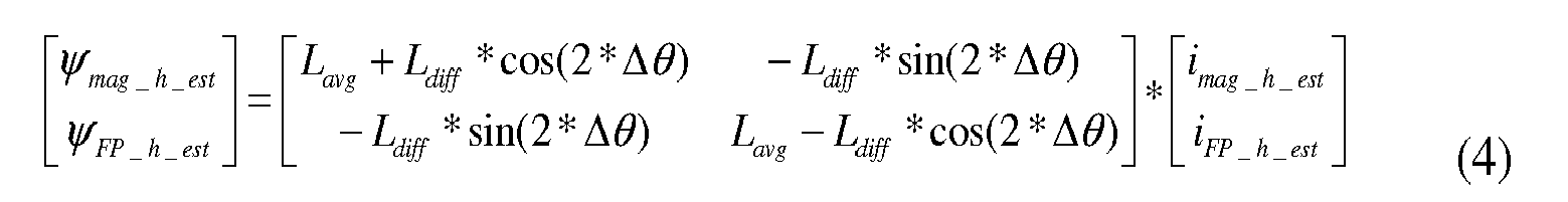
- Substitute equation (3) into equation (4), the carrier high frequency stator current response can be derived as equation (5).

- Therefore, the high frequency current response on the mag-axis of estimated rotor flux reference frame can be represented as equation (6).

- Utilizing equation (6), the estimated rotor position error function g(Δθ) is derived from the measured mag-axis stator current component in below three steps:
- 1. Use a bandpass filter (BPF) to extract the carrier frequency response of magnetization current.

- 2. Demodulate the estimated position error signal from the carrier frequency.

- 3. Extraction of the position error signal by removing the 2-times carrier frequency component using a low pass filter (LPF).

- The estimated speed error signal is thus obtained by propositional-integral regulation (PI regulation) of the estimated position error function signal as shown in equation (10).

- The speed feed-forward signal is generated by low pass filtering of the speed signal applied in the generator control. The low pass filter bandwidth is set to from 2 Hz to 5 Hz.
- The raw estimated speed signal is generated by summing up the speed error signal and the speed feed forward signal. The speed feed forward signal is important for improving the dynamic performance of position error regulation so that the position error can be minimized.

- The estimated rotor position signal is obtained by integration of the estimated speed signal with proper initialization of the position as shown in equation (13). For IPM machine generator mode operation, the initial position is obtained from stator line voltage measurement. For IPM machine motoring mode operation, the initial position can be forced to zero or 180° by the IPM machine d-axis is aligned with the demagnetization flux vector axis using control vectors.

- In practical implementation, the magnetization current is obtained from coordinate transformation of the measured three phase stator current.
- The three phase currents are first transferred from a natural a-b-c coordinate frame into the stator stationary α-β frame using equation (14) and equation (15).


- The stator current magnetization current component and field power component at estimated rotor flux reference frame is thus obtained using equation (16) and equation (17).


-
Fig. 4 illustrated the method for position and speed observation for the position sensorless control scheme shown inFig. 2 with carrier signal injected in the field power flux reference signal. - For the position sensorless control scheme shown
Fig. 3 , a high frequency carrier signal injection is carried out in the magnetization flux reference as given in equation (18).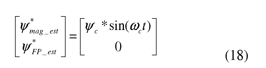
- Substituting equation (18) into equation (4), the carrier signal response of stator current FP-axis component is derived as equation (19).

- The estimated position error function can be obtained using equation (20).

-
Fig. 5 shows the position and speed observation method for the position sensorless control scheme shown inFig. 3 with carrier signal injected in magnetization flux reference signal. -
Fig. 6 shows a flow chart for a position sensorless control system with high frequency flux vector injection method. In 602, the initial position measurement is obtained and provided as an initialization of the control system. In the present embodiment, the initial position is obtained from a stator line voltage measurement, in particular, the measurement of stator Bemf voltage at a generator open circuit condition. Alternatively, the initial position may be obtained from an encoder measurement, prior to an encoder fault. In an IPM motoring mode operation, the initial position may be obtained by an alignment of axis at standstill using flux vector control. - In 604, the flux reference is generated, and in this case, the flux reference vector is generated from power feedback control. The high frequency carrier signal is injected with either a magnetization flux reference or a field power flux reference.
- In 606, the position error is extracted from corresponding current along the field power flux axis or along the magnetization flux axis without high frequency signal injection. In particular, the following steps are taken:
- Current measurement in abc reference frame and transfer to alpha-beta reference frame,
- Current measurement transferred to estimated rotor flux reference frame,
- Using a bandpass filter to extract carrier signal response on current along the field power flux axis or along the magnetization flux axis,
- Extract position error function signal by demodulate the corresponding carrier signal response along the field power flux axis or along the magnetization flux axis.
- In 608, the generator rotor speed is obtained based on proportional-integral (PI) regulation of position error signal with appropriate speed feed forward compensation. In this embodiment, the following steps are taken:
- PI regulation of position error function to get the estimated speed error signal
- Low pass filtering the speed signal applied in generator control to get the speed feed forward signal
- Get the estimated speed by summing up the speed error signal and speed feed forward signal.
- In 610, the estimated rotor angular position is obtained by an integration of the estimated rotor speed signal with appropriate position initialization. In 612, the estimated position and speed signal are applied in the flux vector control system. The sensorless control system thereafter returns to block 604 to determine the next control sample.
- While the invention has been illustrated by a description of various embodiments and while these embodiments have been described in considerable detail, it is not the intention of the applicant to restrict or in any way limit the scope of the appended claims to such detail. Additional advantages and modifications will readily appear to those skilled in the art. The invention in its broader aspects is therefore not limited to the specific details, representative methods, and illustrative examples shown and described. Accordingly, departures may be made from such details without departing from the spirit or scope of applicant's general inventive concept.
Claims (15)
- A method for position sensorless control of an electrical machine, the method comprising:- generating a flux vector reference signal,- modulating the flux vector reference signal by injecting a high frequency signal carrier,- determining a position error function signal from the modulated flux vector reference signal,- estimating the speed of the rotor,- estimating an angular position of the rotor from the estimated speed, and- applying the estimated rotor speed and the estimated angular rotor position to control the electrical machine,wherein the flux vector reference signal is generated from a power feedback control signal.
- A method according to claim 1, wherein the estimated rotor speed and the estimated angular rotor position are applied in a flux vector control system of the electrical machine.
- A method according to claim 1 or 2, wherein the electrical machine comprises any one of an interior permanent magnet machine, a reluctance machine, and an electrical generator.
- A method according to any of the preceding claims, wherein the flux vector reference signal is any one of a magnetization flux reference signal and a field power flux reference signal.
- A method according to any of the preceding claims, further comprising:- generating a magnetization flux reference signal and a field power flux reference signal from a power feedback control signal, and- determining a stator flux amplitude and a load angle from the magnetization flux reference signal and the field power flux reference signal, and- obtaining a stator flux position from at least the load angle.
- A method according to claim 5, wherein the stator flux position is used in transforming the flux vector reference signal from a natural frame to a stator stationary reference frame.
- A method according to claim 5 or 6, wherein the load angle is combined with the estimated angular rotor position to obtain the stator flux position.
- A method according to any of the preceding claims, wherein determining the position error function signal comprises- measuring at least one current signal of the electrical machine,- band-pass filtering the at least one current signal so as to extract a response signal to the injected high frequency signal carrier, and- demodulating the extracted response signal so as to derive the position error function signal.
- A method according to any of the preceding claims, wherein estimating the rotor speed comprises- applying a PI regulator to the position error function signal so as to derive an estimated speed error signal,- low-pass filtering a generator speed control signal so as to derive a speed feed forward signal, and- summing the estimated speed error signal and the speed feed forward signal so as to derive the estimated rotor speed.
- A method according to claim 9, wherein estimating the rotor position comprises the step of integrating the estimated speed so as to derive the estimated rotor position.
- A method according to any of the preceding claims, wherein estimating the rotor position comprises the initialization of the rotor position estimate.
- A method according to claim 11, wherein the initialization comprises obtaining an initial rotor position from any of an estimation by alignment of axis at standstill using flux vector control, a measurement of stator voltage at an open circuit condition, and an encoder measurement prior to an encoder fault.
- A method according to any of the preceding claims, wherein the high frequency signal carrier has a frequency of at least 500 Hz.
- A wind turbine comprising an electrical machine, and an apparatus for position sensorless control of the electrical machine, the apparatus being adapted to carry out the method of any of claims 1 to 13.
- A computer readable medium having a computer program recorded thereon, computer program comprising instructions which, when executed by a processor, make the processor perform a method for position sensorless control of an electrical machine in a wind turbine according to any of the claims 1 to 13.
Applications Claiming Priority (2)
| Application Number | Priority Date | Filing Date | Title |
|---|---|---|---|
| US201161512437P | 2011-07-28 | 2011-07-28 | |
| DKPA201170414 | 2011-07-28 |
Publications (2)
| Publication Number | Publication Date |
|---|---|
| EP2552014A2 true EP2552014A2 (en) | 2013-01-30 |
| EP2552014A3 EP2552014A3 (en) | 2016-08-17 |
Family
ID=46583877
Family Applications (1)
| Application Number | Title | Priority Date | Filing Date |
|---|---|---|---|
| EP12177831.0A Withdrawn EP2552014A3 (en) | 2011-07-28 | 2012-07-25 | A method of position sensorless control of an electrical machine |
Country Status (2)
| Country | Link |
|---|---|
| US (1) | US8884566B2 (en) |
| EP (1) | EP2552014A3 (en) |
Families Citing this family (21)
| Publication number | Priority date | Publication date | Assignee | Title |
|---|---|---|---|---|
| US8624564B2 (en) * | 2010-12-23 | 2014-01-07 | Caterpillar Inc. | Switched reluctance generator initial rotor position estimation |
| RU2540319C2 (en) * | 2013-04-30 | 2015-02-10 | Российская Федерация, от имени которой выступает Министерство промышленности и торговли РФ (МИНПРОМТОРГ РОССИИ) | Valve-inductor electric drive with extreme operating condition |
| US20150249419A1 (en) * | 2014-02-28 | 2015-09-03 | Kia Motors Corporation | System and method for controlling inverter |
| US9705437B2 (en) * | 2014-09-24 | 2017-07-11 | Texas Instruments Incorporated | Angular position estimation for PM motors |
| US9325263B1 (en) * | 2014-11-05 | 2016-04-26 | Stmicroelectronics S.R.L. | Sensorless rotor angle detection circuit and method for a permanent magnet synchronous machine |
| DE102015216309B4 (en) * | 2015-08-26 | 2023-12-28 | Vitesco Technologies GmbH | Method for field-oriented control of a frequency converter for a three-phase motor |
| US20170151875A1 (en) * | 2015-11-30 | 2017-06-01 | Faraday&Future Inc. | Detecting position measurement errors in an electric motor system |
| CN108281970B (en) * | 2017-12-25 | 2019-10-25 | 华中科技大学 | A kind of AC excitation synchronous capacitor and its control method |
| US10895866B1 (en) | 2018-03-08 | 2021-01-19 | Apple Inc. | Position error correction for electric motors |
| FR3083863B1 (en) * | 2018-07-16 | 2020-06-19 | Renault S.A.S | METHOD FOR ESTIMATING THE SPEED AND POSITION OF A ROTOR OF A SYNCHRONOUS COIL ROTOR MACHINE |
| JP7159704B2 (en) * | 2018-08-31 | 2022-10-25 | 株式会社アドヴィックス | motor controller |
| US11196371B2 (en) * | 2020-01-10 | 2021-12-07 | DRiV Automotive Inc. | Sensorless position detection for electric motor |
| EP3902135B1 (en) * | 2020-04-20 | 2023-12-13 | ABB Schweiz AG | Angular position error estimation at standstill for high-frequency voltage injection |
| US11394327B2 (en) | 2020-04-24 | 2022-07-19 | Borgwarner Inc. | Methods and systems for detecting a rotor position and rotor speed of an alternating current electrical machine |
| CN112087175B (en) * | 2020-08-31 | 2021-10-22 | 东南大学 | Speed identification method for permanent magnet synchronous motor |
| CN113517838A (en) * | 2021-04-26 | 2021-10-19 | 臻迪科技股份有限公司 | Rotor position angle determination method and device based on permanent magnet synchronous motor |
| CN113972874B (en) * | 2021-09-28 | 2023-11-10 | 江苏大学 | Position error compensation method for permanent magnet synchronous motor without position sensor control |
| CN114050755B (en) * | 2022-01-12 | 2022-03-29 | 希望森兰科技股份有限公司 | Permanent magnet synchronous motor position observation improved algorithm based on high-frequency rotating voltage injection |
| US11773962B1 (en) | 2022-03-28 | 2023-10-03 | Borgwarner Inc. | Electric drive unit with integrated, variable flow, low-pressure oil cooling system |
| CN114499323B (en) * | 2022-04-02 | 2022-07-12 | 南京凌博电子科技有限公司 | Motor parameter identification method based on high-frequency voltage injection method considering phase resistance |
| CN118399823B (en) * | 2024-07-01 | 2024-09-10 | 成都航天凯特机电科技有限公司 | Self-adaptive motor control method |
Family Cites Families (47)
| Publication number | Priority date | Publication date | Assignee | Title |
|---|---|---|---|---|
| DE3026202A1 (en) * | 1980-07-10 | 1982-02-04 | Siemens AG, 1000 Berlin und 8000 München | TURNFIELD MACHINE DRIVE WITH A CONVERTER-DRIVEN TURNFIELD MACHINE AND A CONVERTER CONTROLLER CONNECTED WITH TWO AC VOLTAGE INTEGRATORS AND A COMPUTER MODEL CIRCUIT |
| DE3034251A1 (en) * | 1980-09-11 | 1982-04-15 | Siemens AG, 1000 Berlin und 8000 München | METHOD AND DEVICE FOR DETERMINING THE RUNNING RESISTANCE OF AN ASYNCHRONOUS MACHINE |
| DE3034275A1 (en) * | 1980-09-11 | 1982-04-22 | Siemens AG, 1000 Berlin und 8000 München | DEVICE FOR DETERMINING THE PARAMETER VALUES FOR STANDAL RESISTANCE, MAIN INDUCTIVITY AND SPREADING INDUCTIVITY OF AN ASYNCHRONOUS MACHINE |
| JPS5925592A (en) * | 1982-08-02 | 1984-02-09 | Toyota Central Res & Dev Lab Inc | Control of inverter and device therefor |
| EP0127158B1 (en) * | 1983-05-27 | 1986-08-20 | Siemens Aktiengesellschaft | Method and apparatus to derive the flux vector of an induction machine from the stator current and the stator voltage, and application thereof |
| NO851324L (en) * | 1984-05-18 | 1985-11-19 | Siemens Ag | PROCEDURE AND APPARATUS FOR AA DETERMINE A TRIANGLE-MACHINE FLUCH VECTOR. |
| DE3418573A1 (en) * | 1984-05-18 | 1985-12-05 | Siemens AG, 1000 Berlin und 8000 München | METHOD AND DEVICE FOR STABILIZING THE LOCATION CURVE OF A VECTOR FORMED BY INTEGRATION |
| JPH0636676B2 (en) * | 1985-03-01 | 1994-05-11 | 勲 高橋 | Control method of PWM inverter |
| GB8603800D0 (en) * | 1986-02-15 | 1986-03-19 | Brown J E | Vector control system |
| JPS6318995A (en) * | 1986-07-11 | 1988-01-26 | Toshiba Corp | Voltage controller for wound-rotor type induction generator |
| US4707651A (en) * | 1986-07-22 | 1987-11-17 | Westinghouse Electric Corp. | Voltage-controlled field-oriented induction motor control system |
| US4814677A (en) * | 1987-12-14 | 1989-03-21 | General Electric Company | Field orientation control of a permanent magnet motor |
| JP2821679B2 (en) * | 1988-07-19 | 1998-11-05 | 株式会社日立製作所 | Method and apparatus for generating gate signal of PWM inverter, PWM inverter apparatus |
| US4968925A (en) * | 1989-08-07 | 1990-11-06 | General Electric Company | Universal field-oriented controller |
| JPH03265466A (en) * | 1990-03-13 | 1991-11-26 | Toshiba Corp | Control method for cyclo-converter |
| US5334923A (en) * | 1990-10-01 | 1994-08-02 | Wisconsin Alumni Research Foundation | Motor torque control method and apparatus |
| US5272429A (en) * | 1990-10-01 | 1993-12-21 | Wisconsin Alumni Research Foundation | Air gap flux measurement using stator third harmonic voltage and uses |
| US5144216A (en) * | 1991-10-02 | 1992-09-01 | General Electric Company | High speed flux feedback for tuning a universal field oriented controller capable of operating in direct and indirect field orientation modes |
| US5559419A (en) * | 1993-12-22 | 1996-09-24 | Wisconsin Alumni Research Foundation | Method and apparatus for transducerless flux estimation in drives for induction machines |
| DE19703248B4 (en) * | 1997-01-29 | 2006-01-26 | Siemens Ag | Method and device for determining a rotor angular velocity of an encoderless, field-oriented rotary field machine |
| JP3097610B2 (en) * | 1997-03-07 | 2000-10-10 | 富士電機株式会社 | Induction machine variable speed drive |
| FI110372B (en) * | 1999-02-15 | 2002-12-31 | Abb Industry Oy | Procedure for control of electric machine and converter |
| US6014006A (en) * | 1999-06-24 | 2000-01-11 | Ford Global Technologies, Inc. | Induction motor control system with speed and flux estimation |
| US6163127A (en) | 1999-11-22 | 2000-12-19 | General Motors Corporation | System and method for controlling a position sensorless permanent magnet motor |
| JP4475368B2 (en) * | 2000-03-10 | 2010-06-09 | 富士電機システムズ株式会社 | Speed sensorless vector controller |
| JP2002095298A (en) * | 2000-09-14 | 2002-03-29 | Toshiba Corp | Motor controller |
| US6492788B1 (en) * | 2000-11-10 | 2002-12-10 | Otis Elevator Company | Method and apparatus for encoderless operation of a permanent magnet synchronous motor in an elevator |
| US6448735B1 (en) * | 2001-04-26 | 2002-09-10 | Abb Automation Inc. | Controller for a wound rotor slip ring induction machine |
| US6784634B2 (en) * | 2001-09-14 | 2004-08-31 | Edwin A. Sweo | Brushless doubly-fed induction machine control |
| JP4370754B2 (en) | 2002-04-02 | 2009-11-25 | 株式会社安川電機 | Sensorless control device and control method for AC motor |
| US6768284B2 (en) * | 2002-09-30 | 2004-07-27 | Eaton Corporation | Method and compensation modulator for dynamically controlling induction machine regenerating energy flow and direct current bus voltage for an adjustable frequency drive system |
| EP1612928B9 (en) * | 2004-07-01 | 2007-05-09 | ABB Oy | Method for determining rotor flux vector of AC electrical machine |
| DE602004020349D1 (en) | 2004-10-28 | 2009-05-14 | Abb Oy | Method for estimating the rotor speed and position of a permanent magnet synchronous machine |
| US7193383B2 (en) * | 2005-07-06 | 2007-03-20 | Honeywell International, Inc. | Enhanced floating reference frame controller for sensorless control of synchronous machines |
| US7495404B2 (en) * | 2005-08-17 | 2009-02-24 | Honeywell International Inc. | Power factor control for floating frame controller for sensorless control of synchronous machines |
| ATE463073T1 (en) | 2007-07-26 | 2010-04-15 | Baumueller Nuernberg Gmbh | SYSTEM FOR DETERMINING POSITION AND SPEED OF A PERMANENT MAGNET RUNNER OF AN ELECTRICAL MACHINE |
| EP2327148B1 (en) | 2008-08-29 | 2018-07-11 | Vestas Wind Systems A/S | A method and a controlling arrangement for controlling an ac generator |
| EP2159910A1 (en) * | 2008-08-29 | 2010-03-03 | Vestas Wind Systems A/S | Direct power and stator flux vector control of a generator for wind energy conversion system |
| WO2010049412A1 (en) * | 2008-10-27 | 2010-05-06 | Vestas Wind Systems A/S | Direct power and stator flux vector control of a generator for wind energy conversion system |
| US8242721B2 (en) | 2008-10-31 | 2012-08-14 | R&D Dynamics Corporation | Position-sensorless control system and method of operation for a synchronous motor |
| US20100237817A1 (en) * | 2009-03-23 | 2010-09-23 | Jingbo Liu | Method and Apparatus for Estimating Rotor Position in a Sensorless Synchronous Motor |
| US8525454B2 (en) * | 2009-03-26 | 2013-09-03 | Mitsubishi Electric Corporation | Controller for AC rotary machine |
| FR2944659B1 (en) * | 2009-04-21 | 2011-04-01 | Schneider Toshiba Inverter | METHOD FOR DETERMINING THE POSITION OF THE FLOW VECTOR OF AN ENGINE |
| US8076881B1 (en) * | 2009-06-16 | 2011-12-13 | Curtiss-Wright Electro-Mechanical Corp. | System and method for controlling an electric motor |
| ES2592178T3 (en) * | 2009-06-19 | 2016-11-28 | Vestas Wind Systems A/S | Method for determining the rotor position of an electric generator in a wind turbine |
| US8248039B2 (en) * | 2009-06-30 | 2012-08-21 | Vestas Wind Systems A/S | Control system for an electrical generator and method for controlling an electrical generator |
| US8339081B2 (en) | 2009-09-11 | 2012-12-25 | GM Global Technology Operations LLC | Method and apparatus for low speed permanent magnet motor operation |
-
2012
- 2012-07-25 EP EP12177831.0A patent/EP2552014A3/en not_active Withdrawn
- 2012-07-27 US US13/560,444 patent/US8884566B2/en active Active
Non-Patent Citations (1)
| Title |
|---|
| None |
Also Published As
| Publication number | Publication date |
|---|---|
| EP2552014A3 (en) | 2016-08-17 |
| US8884566B2 (en) | 2014-11-11 |
| US20130093375A1 (en) | 2013-04-18 |
Similar Documents
| Publication | Publication Date | Title |
|---|---|---|
| US8884566B2 (en) | Method of position sensorless control of an electrical machine | |
| US9438153B2 (en) | Rotary electric machine control device | |
| JP4059039B2 (en) | Control device for synchronous motor | |
| EP2552015B1 (en) | A method of position sensorless control of an electrical machine | |
| CN103825525B (en) | A kind of permagnetic synchronous motor without sensor speed estimation method of improvement | |
| EP2924874B1 (en) | Control device for ac rotating machine | |
| TWI559672B (en) | Angle estimation control systems | |
| CN105811831A (en) | Tracking method of rotor position of salient pole permanent magnet synchronous motor in motion state | |
| JP5543388B2 (en) | Control device for permanent magnet synchronous motor | |
| Chen et al. | Self-sensing control of permanent-magnet synchronous machines with multiple saliencies using pulse-voltage-injection | |
| Wu et al. | Design of position estimation strategy of sensorless interior PMSM at standstill using minimum voltage vector injection method | |
| JP4120420B2 (en) | Motor control device | |
| JP5618854B2 (en) | Synchronous motor drive system | |
| Liu et al. | A new sensorless control strategy by high-frequency pulsating signal injection into stationary reference frame | |
| Rambetius et al. | Sensorless control of wound rotor synchronous machines using the switching of the rotor chopper as a carrier signal | |
| Boldea et al. | “Active flux” orientation vector sensorless control of IPMSM | |
| JP7304891B2 (en) | Rotating machine control device and electric vehicle control device | |
| Lashkevich et al. | Investigation of self-sensing rotor position estimation methods for synchronous homopolar motor in traction applications | |
| Hirakawa et al. | Estimated position error compensation method considering impact of speed and load in permanent magnet synchronous motor position sensorless control based on high-frequency voltage injection | |
| JP5798513B2 (en) | Method and apparatus for detecting initial magnetic pole position of permanent magnet synchronous motor, and control apparatus for permanent magnet synchronous motor | |
| Uzel et al. | Estimator comparison for resolver motivated sensorless rotor position estimation of wound rotor synchronous motors | |
| Imai et al. | Position sensorless control for wound-field synchronous motor with double three-phase wound stator using extended electromotive force model | |
| Yu et al. | Rotating high-Frequency voltage injection based on characteristic harmonic elimination | |
| Čolović et al. | Rotor flux estimation for speed sensorless induction generator used in wind power application | |
| Yunxiang et al. | A study on high frequency signal injection method of aiming at detecting the rotor position of the salient-pole brushless DC motor |
Legal Events
| Date | Code | Title | Description |
|---|---|---|---|
| PUAI | Public reference made under article 153(3) epc to a published international application that has entered the european phase |
Free format text: ORIGINAL CODE: 0009012 |
|
| AK | Designated contracting states |
Kind code of ref document: A2 Designated state(s): AL AT BE BG CH CY CZ DE DK EE ES FI FR GB GR HR HU IE IS IT LI LT LU LV MC MK MT NL NO PL PT RO RS SE SI SK SM TR |
|
| AX | Request for extension of the european patent |
Extension state: BA ME |
|
| RAP1 | Party data changed (applicant data changed or rights of an application transferred) |
Owner name: VESTAS WIND SYSTEMS A/S |
|
| PUAL | Search report despatched |
Free format text: ORIGINAL CODE: 0009013 |
|
| AK | Designated contracting states |
Kind code of ref document: A3 Designated state(s): AL AT BE BG CH CY CZ DE DK EE ES FI FR GB GR HR HU IE IS IT LI LT LU LV MC MK MT NL NO PL PT RO RS SE SI SK SM TR |
|
| AX | Request for extension of the european patent |
Extension state: BA ME |
|
| RIC1 | Information provided on ipc code assigned before grant |
Ipc: H02P 21/00 20160101AFI20160713BHEP Ipc: H02P 6/18 20160101ALI20160713BHEP |
|
| STAA | Information on the status of an ep patent application or granted ep patent |
Free format text: STATUS: THE APPLICATION HAS BEEN PUBLISHED |
|
| STAA | Information on the status of an ep patent application or granted ep patent |
Free format text: STATUS: THE APPLICATION IS DEEMED TO BE WITHDRAWN |
|
| 18D | Application deemed to be withdrawn |
Effective date: 20170218 |