EP2551981B1 - Anordnung zur Überwachung eines Erdleiters durch Messung der Impedanz - Google Patents
Anordnung zur Überwachung eines Erdleiters durch Messung der Impedanz Download PDFInfo
- Publication number
- EP2551981B1 EP2551981B1 EP12354041.1A EP12354041A EP2551981B1 EP 2551981 B1 EP2551981 B1 EP 2551981B1 EP 12354041 A EP12354041 A EP 12354041A EP 2551981 B1 EP2551981 B1 EP 2551981B1
- Authority
- EP
- European Patent Office
- Prior art keywords
- conductor
- impedance
- voltage
- generator
- circuit
- Prior art date
- Legal status (The legal status is an assumption and is not a legal conclusion. Google has not performed a legal analysis and makes no representation as to the accuracy of the status listed.)
- Active
Links
Images

Classifications
-
- H—ELECTRICITY
- H02—GENERATION; CONVERSION OR DISTRIBUTION OF ELECTRIC POWER
- H02H—EMERGENCY PROTECTIVE CIRCUIT ARRANGEMENTS
- H02H5/00—Emergency protective circuit arrangements for automatic disconnection directly responsive to an undesired change from normal non-electric working conditions with or without subsequent reconnection
- H02H5/10—Emergency protective circuit arrangements for automatic disconnection directly responsive to an undesired change from normal non-electric working conditions with or without subsequent reconnection responsive to mechanical injury, e.g. rupture of line, breakage of earth connection
- H02H5/105—Emergency protective circuit arrangements for automatic disconnection directly responsive to an undesired change from normal non-electric working conditions with or without subsequent reconnection responsive to mechanical injury, e.g. rupture of line, breakage of earth connection responsive to deterioration or interruption of earth connection
Definitions
- the invention relates to a device for monitoring an earth conductor capable of measuring the grounding impedance.
- the earth conductor also called protective earth (PE) connects the metal carcass of an electrical equipment to the ground. It thus ensures the protection of the user and the equipment when an insulation fault appears.
- PE protective earth
- the neutral N-conductor and conductor of the distribution network are connected to separate earth connections.
- the diagram "TN” the carcass and the neutral conductor N are connected to a common ground.
- the continuity of the PE conductor between the power socket and the load is generally verified by means of a communication protocol. In the event of a break in the conductor, communication is interrupted, which triggers the opening of a circuit breaker.
- the connection between the PE conductor and earth is not constantly checked in the electrical installations. This connection can be empirically controlled by measuring the voltage between the neutral conductor N and the ground conductor PE. If the voltage N-PE is close to 0 V, it means that the connection is ensured.
- the impedance of the PE conductor does not exceed a threshold value. Indeed, the grounding impedance is likely to increase over time and represents a risk to the user beyond a certain value.
- the document GB2167618 discloses an electrical protection circuit provided with means for determining the impedance of the PE conductor.
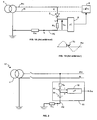
- the Figure 1A represents a part of the circuit diagram of such a protection circuit.
- a thyristor 2 and a measuring resistor R M are connected in series between the PH phase conductor of a transformer 4 and the PE earth conductor (shown in a thicker line).
- the impedance of the PE conductor is determined by measuring the voltage V M across the resistor R M , when an excitation signal is injected into the PE conductor.
- the voltage V M is supplied to a processing circuit 6, which controls the opening of a residual current circuit breaker 8 when the impedance Z PE exceeds 100 ⁇ .
- the Figure 1B represents in dotted lines the signal on the phase PH of the electrical network, that is to say the AC voltage from the transformer 4, and in full line the excitation voltage V E applied to the measurement resistor R M for the determination of the impedance Z PE .
- the excitation voltage V E corresponds to a downward portion of the voltage PH of the network, between 0 V and 10 V. It is obtained by activating the thyristor 2 for a short period (100 ⁇ s), which causes a current of I E excitation in the resistance R M and the impedance Z PE .
- the thyristor is controlled by a phase delay circuit (not shown).
- This protection circuit therefore uses the phase of the network as excitation source for the measurement of the impedance Z PE .
- the excitation voltage V E then undergoes sudden variations, because of the fluctuations of the network. However, this instability is detrimental for the measurement of the impedance Z PE .
- the voltage V E also depends on the accuracy of the phase delay circuit which controls the thyristor 2. Such a control circuit is heavy to implement.
- the document US2003 / 156367 describes an electrical protection device with an ohmmeter connected to measure the impedance of loop in the neutral conductor and the ground conductor of a power supply circuit.
- the ohmmeter has its own voltage source and a coupling impedance.
- the measured loop impedance is compared with a threshold, to trigger an alert signal if necessary.
- the invention relates to a device for monitoring a ground conductor easy to implement and for accurately measuring the impedance of the earth conductor.
- a calibrated and stable voltage generator for measuring the impedance of a ground conductor.
- the generator is connected between the earth conductor and a phase or neutral conductor of an electrical network, so as to generate an excitation current through the earth conductor. By measuring this excitation current, it is possible to calculate the impedance of the earth conductor.
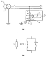
- the figure 2 represents a preferred embodiment of a monitoring device with measurement of the impedance of the earth conductor.
- this monitoring device is intended to control a differential circuit-breaker when the impedance Z PE exceeds a threshold value because of the aging or rupture of the earth conductor.
- the monitoring device 10 is connected to the earth conductor PE of an electrical installation and to a distribution network 12 comprising at least two active conductors
- the distribution network 12 is single-phase. It comprises a phase conductor PH and a neutral conductor N coming from a transformer 4.
- the neutral N and the conductor PE are all two connected to the ground and each have a grounding.
- the installation is connected to the ground according to the "TT" regime.
- the device 10 comprises a current sensor 13 and a voltage generator 14 connected in series between the PH phase and the PE conductor.
- the device 10 and the network 12 thus form a PH-PE loop in which, in addition to the network signal 12, a measurement signal from the generator 14 is propagated. This measurement signal passes through the sensor 13, the PH phase conductor. and the PE ground conductor.
- the generator 14 is a DC voltage generator V, preferably between 5 V and 24 V (very low safety voltage).
- a current 1, continuous, is superimposed on the alternating current from phase PH.
- the current sensor 13 measures the direct current I that flows through the PE conductor. It is, for example, formed of a precision resistor, a Hall effect sensor, fluxgate effect, a magneto-resistive sensor ...
- the device 10 comprises a limiting impedance R M of the current, connected to the phase conductor PH in series with the sensor 13 and the generator 14.
- the limiter R M aims to withstand the stresses of the network 12 (voltage 230 V , shock waves ...) and to limit the direct current 1 injected into the network.
- the limiter R M is preferably formed of a resistance of between 1 k ⁇ and 50 k ⁇ .
- a processing circuit 16 receives at the input the current 1 measured by the sensor 13 and the voltage V imposed by the generator 14, in order to calculate at the output the impedance of the conductor PE, Z PE .
- the circuit 16 is, for example, a microprocessor.
- the Z PE impedance calculation is based on Ohm's law.
- the impedance Z PH of the phase conductor in the calculation of Z PE (relation 1), one will carry out beforehand an impedance measurement in the loop PH-N.
- the impedance of the PH-N loop is equal to the sum of the impedance Z PH of the phase conductor and the impedance Z N of the neutral conductor. However, the impedances Z PH and Z N are substantially equal. We can therefore calculate a value of the impedance Z PH from the impedance of the loop PH-N.
- the monitoring circuit 10 will preferably be used to measure the impedance Z N , connecting it to the PH and N conductors and using the same calculation method.
- the figure 3 represents a second embodiment of a monitoring device, in which the DC voltage source is replaced by a low-frequency voltage source 14 '.
- the measurement principle is similar to that described in relation to the figure 2 .
- an alternating signal is used at a frequency between 1 Hz and 20 Hz.
- the impedance of the ground conductor Z PE (at low frequency) is calculated from the voltage V BF of the generator 14 'and the current I BF measured by the current sensor 13.
- the amplitude of the low frequency signal is preferably between 5 V and 24 V.
- the impedance of a ground conductor being essentially resistive, the value of Z PE obtained at low frequency is substantially identical to that obtained by mounting the figure 2 .
- a switch K is connected in series with the limiter R M and the voltage generator 14 or 14 '( Fig.2 or 3 ). It disconnects the monitor 10 when measuring the impedance Z PE is not required. For example, it may be desired to perform an impedance test only at the beginning of the start-up of the equipment.
- the impedance Z PE of the earth conductor is measured from excitation signals, continuous in the embodiment of the figure 2 (1 and V) and at low frequency in the embodiment of the figure 3 (I BF and V BF ).
- the excitation signal is therefore distinct from the mains voltage, in the sense that it has a frequency and / or an amplitude different from those of the network.
- the figure 4 represents an implementation variant for eliminating the frequency of the network 12.
- the limiting impedance R M constitutes a filter, for example of the band-cut type.
- This filter preferably comprises a capacitor C and an inductor L connected in parallel (parallel LC circuit).
- the values of L and C are chosen so as to obtain a frequency of resonance equal to the frequency of the network.
- a resistor r is preferably connected in series with the capacitor C, for the protect against overvoltage when the device 10 is connected to the PH phase.
- the impedance of the parallel LC circuit is high, which makes it possible to reduce the leakage current to earth to a negligible value.
- the impedance R M is rather low, which allows on the one hand to reduce the excitation signal for the measurement and on the other hand to obtain a high measurement accuracy for low values from Z PE .
- Such filters are particularly simple to implement, particularly in the case of figure 2 .
- the filtering of the mains voltage improves the accuracy of the measurement of the impedance Z PE .
- the time required for this measurement is greater, especially when the excitation signal is at low frequency.
- the figure 5 represents an improvement of the monitoring device to reduce network constraints on the measurement of the impedance Z PE .
- the monitoring device 10 is connected to the neutral conductor N of the network 12 and then the impedance of the N-PE loop is measured. This eliminates the voltage of the network and the associated filter.
- the impedance R M can be reduced to a small value (a few ohms), or even suppressed.
- the device 10 advantageously comprises a neutral conductor recognition circuit 18 and a connection circuit of the generator 14 to the neutral conductor.
- This connection circuit comprises for example a three-state connection relay K '.
- the generator 14 In a first state of the relay K ', the generator 14 is connected to the phase conductor PH of the network 12. In a second state, the generator 14 is connected to the neutral conductor N. The device 10 is disconnected from the network 12 in a third state of the relay K '.
- the circuit 18 controls the relay K 'so that it connects the generator 14 to the neutral N.
- processing circuit 16 and the control circuit 18 may form a single electronic circuit.
- the excitation source is a voltage generator isolated from the electrical network.
- the measurement signal emitted by this source is therefore not sensitive to fluctuations in the network.
- the impedance Z PE of the earth conductor can then be precisely determined.
- the monitoring devices described above may be connected to an earthed electrical installation according to the "TT" regime or the "TN” regime.
- the PE conductor and the N conductor share the same ground.
- the device is however not operational in "IT" mode, for which the neutral N of the transformer is isolated. Indeed, a current loop can not be formed in this case, and the excitation signals do not run through the PE conductor.
- the device can be integrated in charging stations of electric vehicles. Such installations require a high degree of protection. Indeed, it is essential to ensure the safety of people by verifying the proper grounding of the electric vehicle when charging.
- the embodiment of the figure 2 is particularly suitable because the measurement of the impedance Z PE is not sensitive to the filter capacitors of the electric vehicle, arranged between the phase and the earth conductor.
- monitoring device has been described in connection with a single-phase distribution network. It could, however, be connected to a two-phase or three-phase network.
- the calculation of the Z PE impedance is based on two physical quantities, which are the current and the voltage in the PH-PE (or N-PE) loop.
- the voltage generator could therefore be replaced by a current generator, and the measurement of the current by a voltage measurement.
- the excitation source (not perfect) can be any, which will facilitate its realization.
Landscapes
- Measurement Of Resistance Or Impedance (AREA)
- Testing Of Short-Circuits, Discontinuities, Leakage, Or Incorrect Line Connections (AREA)
Claims (8)
- Vorrichtung zur Überwachung (10) eines Erdleiters (PE), die dazu bestimmt ist, mit einem Phasenleiter (PH) oder einem Neutralleiter (N) eines Stromnetzes (12) verbunden zu werden und umfasst:- einen Aufnehmer (13) für eine erste elektrische Größe, der zwischen dem Phasen- oder dem Neutralleiter und dem Erdleiter angeordnet ist,- einen Generator (14, 14') einer von derjenigen des Stromnetzes verschiedenen zweiten elektrischen Größe, der mit dem Aufnehmer in Reihe geschaltet ist,- eine Verarbeitungsschaltung (16), die dazu ausgelegt ist, die elektrische Impedanz (ZPE) des Erdleiters anhand der ersten und der zweiten elektrischen Größe, die aus einer Spannung (V, VBF) und einem in dem Erdleiter fließenden Strom (I, IBF) ausgewählt sind, zu berechnen,dadurch gekennzeichnet, dass sie umfasst:- eine Schaltung (K') zum Anschließen des Generators (14, 14') an den Phasenleiter (PH) in einem ersten Zustand, an den Neutralleiter (N) in einem zweiten Zustand und zum Trennen des Generators in einem dritten Zustand, sowie- eine Schaltung (18) zum Erkennen des Neutralteiters (N), die dazu ausgelegt ist, die Anschlussschaltung (K') in dem zweiten Zustand zu steuern.
- Vorrichtung nach Anspruch 1, dadurch gekennzeichuet, dass die erste elektrische Größe der in dem Erdleiter fließende Strom (I, IBF) ist und die zweite elektrische Größe eine Messspannung (V, VBF) ist.
- Vorrichtung nach Anspruch 2, dadurch gekennzeichnet, dass der Messspannungsgenerator ein Generator (14) für Gleichspannung (V) zwischen 5 V und 24 V ist.
- Vorrichtung nach Anspruch 2, dadurch gekennzeichnet, dass der Messspannungsgenerator ein Generator (14`) für Wechselspannung (VBF) mit einer Frequenz zwischen 1 Hz und 20 Hz ist.
- Vorrichtung nach einem der Ansprüche 1 bis 4, dadurch gekennzeichnet, dass sie ein Filter umfasst, das dazu ausgelegt ist, die Spannung des Stromnetzes zu beseitigen.
- Vorrichtung nach einem der Ansprüche 1 bis 5, dadurch gekennzeichnet, dass sie eine Impedanz zur Begrenzung (RM) des in dem Erdleiter fließenden Stroms umfasst.
- Vorrichtung nach Anspruch 6, dadurch gekennzeichnet, dass die Begrenzungsimpedanz (RM) eine Drossel (L) und einen Kondensator (C) umfasst, die parallelgeschaltet und derart gewählt sind, dass eine Resonanzfrequenz, die gleich der Betriebsfrequenz des Stromnetzes ist, erhalten wird.
- Vorrichtung nach einem der Ansprüche 1 bis 7, dadurch gekennzeichnet, dass die Anschlussschaltung ein Relais mit drei Zuständen (K') umfasst.
Applications Claiming Priority (1)
| Application Number | Priority Date | Filing Date | Title |
|---|---|---|---|
| FR1102383A FR2978556B1 (fr) | 2011-07-29 | 2011-07-29 | Dispositif de surveillance d'un conducteur de terre avec mesure de l'impedance |
Publications (2)
| Publication Number | Publication Date |
|---|---|
| EP2551981A1 EP2551981A1 (de) | 2013-01-30 |
| EP2551981B1 true EP2551981B1 (de) | 2014-04-09 |
Family
ID=46642455
Family Applications (1)
| Application Number | Title | Priority Date | Filing Date |
|---|---|---|---|
| EP12354041.1A Active EP2551981B1 (de) | 2011-07-29 | 2012-07-26 | Anordnung zur Überwachung eines Erdleiters durch Messung der Impedanz |
Country Status (4)
| Country | Link |
|---|---|
| EP (1) | EP2551981B1 (de) |
| CN (1) | CN102901878B (de) |
| ES (1) | ES2464097T3 (de) |
| FR (1) | FR2978556B1 (de) |
Families Citing this family (12)
| Publication number | Priority date | Publication date | Assignee | Title |
|---|---|---|---|---|
| FR3007844B1 (fr) | 2013-06-26 | 2015-07-17 | Schneider Electric Ind Sas | Dispositif d'estimation de l'impedance d'une liaison electrique de terre, procede d'estimation et systeme d'alimentation electrique associes |
| FR3016250B1 (fr) * | 2014-01-08 | 2016-02-05 | Electricite De France | Dispositif de mesure electrique equipant un appareil electrique pour mesurer la resistance d'une prise de terre d'une installation electrique qui alimente l'appareil |
| WO2015104505A1 (fr) * | 2014-01-08 | 2015-07-16 | Electricite De France | Dispositif de mesure électrique pour mesurer la résistance d'une prise de terre d'une installation électrique |
| CN106159891B (zh) * | 2016-07-07 | 2018-07-24 | 中车大连机车车辆有限公司 | 直流电传动内燃机车主电路接地保护方法 |
| CN106483382A (zh) * | 2016-11-23 | 2017-03-08 | 云南电网有限责任公司电力科学研究院 | 一种gis电路回路电阻测量仪及测量方法 |
| CN106772005A (zh) * | 2016-12-12 | 2017-05-31 | 深圳市八戒电工技术有限公司 | 一种继电器触点寿命检测电路及方法 |
| DE102017110955A1 (de) * | 2017-05-19 | 2018-11-22 | Dr. Ing. H.C. F. Porsche Aktiengesellschaft | Detektion eines Schutzleiterausfalls mittels aktiver Schirmung |
| DE102018111536B3 (de) * | 2018-05-15 | 2019-09-19 | Te Connectivity Germany Gmbh | Verfahren zur Steuerung eines Ladevorgangs eines Elektrofahrzeugs und Ladekabel |
| WO2019229744A1 (en) | 2018-05-28 | 2019-12-05 | Shkury Ezra | Ground monitoring tester |
| DE102019132242B4 (de) * | 2019-11-28 | 2021-06-17 | Bender Gmbh & Co. Kg | Verwendungen einer Schaltungsanordnung mit aktiver Messspannung zur Bestimmung eines Isolationswiderstands in einem oder mehreren ungeerdeten Stromversorgungssystem(en) |
| ES2892026B2 (es) * | 2020-07-27 | 2022-10-13 | Aplicaciones Tecnologicas S A | Sistema y procedimiento de autocalibración para aparatos autónomos de medida de impedancia de bucle y de puesta a tierra |
| WO2024199672A1 (en) * | 2023-03-31 | 2024-10-03 | Huawei Digital Power Technologies Co., Ltd. | An earthing interface and method for providing functional earthing |
Family Cites Families (12)
| Publication number | Priority date | Publication date | Assignee | Title |
|---|---|---|---|---|
| DE3429067A1 (de) * | 1984-08-07 | 1986-02-20 | Elektromanufaktur Zangenstein Hanauer GmbH & Co, 8471 Altendorf | Schaltung zur kontinuierlichen ueberwachung des erdungswiderstandes elektrischer geraete |
| GB8429523D0 (en) | 1984-11-22 | 1985-01-03 | Indep Tv News Ltd | Earth validity tester |
| GB2199707B (en) * | 1984-11-22 | 1989-04-19 | Independent Television News Li | Electrical protective circuits |
| IT1237156B (it) * | 1989-12-22 | 1993-05-24 | Teuco Guzzini Srl | Dispositivo elettronico di sicurezza per collegamenti a prese di terra |
| US20030156367A1 (en) * | 2002-02-01 | 2003-08-21 | Macbeth Bruce F. | Arc fault circuit interrupter with upstream impedance detector |
| US7023680B1 (en) * | 2003-10-29 | 2006-04-04 | Psg Enterprises, Inc. | Transient voltage protection and ground status monitoring apparatus and method |
| EP1936773A1 (de) * | 2006-12-22 | 2008-06-25 | Abb Research Ltd. | System und Verfahren zur Detektion eines vergessenen Schutzleiters einer elektrischen Anlage |
| CN201047991Y (zh) * | 2006-12-28 | 2008-04-16 | 刘涌 | 电力线载波智能控制器及电力线载波控制系统 |
| US7616010B2 (en) * | 2007-04-30 | 2009-11-10 | Rockwell Automation Technologies, Inc. | Line impedance measurement method and system |
| CN101236222B (zh) * | 2008-02-25 | 2011-02-09 | 四川电力试验研究院 | 运用冲击电流测量接地网电阻和电感的方法 |
| CN101719660B (zh) * | 2009-12-14 | 2012-07-04 | 张文会 | 小电流系统接地保护装置自动复归方法 |
| CN101949979A (zh) * | 2010-08-06 | 2011-01-19 | 国电龙源电气有限公司 | 一种变压器接地线电阻的测量方法 |
-
2011
- 2011-07-29 FR FR1102383A patent/FR2978556B1/fr not_active Expired - Fee Related
-
2012
- 2012-07-19 CN CN201210250518.1A patent/CN102901878B/zh active Active
- 2012-07-26 ES ES12354041.1T patent/ES2464097T3/es active Active
- 2012-07-26 EP EP12354041.1A patent/EP2551981B1/de active Active
Also Published As
| Publication number | Publication date |
|---|---|
| FR2978556A1 (fr) | 2013-02-01 |
| CN102901878A (zh) | 2013-01-30 |
| EP2551981A1 (de) | 2013-01-30 |
| CN102901878B (zh) | 2018-04-03 |
| ES2464097T3 (es) | 2014-05-30 |
| FR2978556B1 (fr) | 2014-03-07 |
Similar Documents
| Publication | Publication Date | Title |
|---|---|---|
| EP2551981B1 (de) | Anordnung zur Überwachung eines Erdleiters durch Messung der Impedanz | |
| EP2755848B1 (de) | Verfahren zur überwachung des kapazitiven filters eines batterieladegerätes | |
| EP2820733B1 (de) | Feststellen von leckströmen mit gleichstromanteil in einem fahrzeug | |
| EP2864148B1 (de) | Vorrichtung zur messung des widerstands in einem masseanschluss und fahrzeuginternes ladegerät mit solch einer vorrichtung | |
| EP2820433B1 (de) | Elektrizitätszähler und verfahren zur feststellung des zustandes eines schutzschalters einer mit diesem zähler verbundenen vorrichtung | |
| EP2446281B1 (de) | Stromzähler mit unisoliertem stromsensor und sperrschütz | |
| EP3126783A1 (de) | Vorrichtung zur messung von mindestens einer physikalischen grösse einer elektrischen installation | |
| EP2648008A1 (de) | Isolierungskontrollsystem für gesichertes Stromnetz | |
| EP3483999B1 (de) | Elektrische verbindung für die übertragung einer hochspannung über wechselstrom an ein benutzergerät | |
| EP3462187B1 (de) | Spannungspräsenz-anzeigesystem in einem hochspannungsnetz | |
| EP2818879B1 (de) | Vorrichtung zum Schätzen der Impedanz einer elektrischen Erdverbindung, entsprechendes Schätzverfahren und entsprechendes Stromversorgungssystem | |
| FR3040494B1 (fr) | Systeme electrique comportant un dispositif d'evaluation d'un defaut d'isolation, vehicule automobile comportant un tel systeme electrique et procede d'evaluation d'un defaut d'isolation | |
| EP2901167B1 (de) | Verfahren und vorrichtung zur bestimmung der position eines isolationsfehlers | |
| EP3009851B1 (de) | Zähler zum aufdecken von betrug durch bypass | |
| EP3016818B1 (de) | Verfahren zur bestimmung der anwesenheit eines it-versorgungsnetzes zur versorgung einer kraftfahrzeug-batterieladevorrichtung und entsprechende ladevorrichtung | |
| WO2020074128A1 (fr) | Aeronef comprenant une installation electrique utilisant une haute tension a courant continu | |
| EP3771055B1 (de) | Güberstrom-erkennungsvorrichtung in einem elektrischen leistungsschaltkreis umfassend einen filter zur steuerung der ladung eines kondensators | |
| EP2718732B1 (de) | Vorrichtung und entsprechendes verfahren zur messung des widerstandes des erdschlusses einer elektrischen vorrichtung | |
| FR2983303A1 (fr) | Mesure de la resistance au sol d'une structure metallique ou de la resistivite du sol, en utilisant une structure metallique enterree de grande taille, eventuellement sous protection cathodique | |
| CN116148648B (zh) | 检测断路器的断开或闭合状态 | |
| EP3015873A1 (de) | Detektionsverfahren eines betrügerischen by-pass-versuchs an einem zähler |
Legal Events
| Date | Code | Title | Description |
|---|---|---|---|
| PUAI | Public reference made under article 153(3) epc to a published international application that has entered the european phase |
Free format text: ORIGINAL CODE: 0009012 |
|
| AK | Designated contracting states |
Kind code of ref document: A1 Designated state(s): AL AT BE BG CH CY CZ DE DK EE ES FI FR GB GR HR HU IE IS IT LI LT LU LV MC MK MT NL NO PL PT RO RS SE SI SK SM TR |
|
| AX | Request for extension of the european patent |
Extension state: BA ME |
|
| 17P | Request for examination filed |
Effective date: 20130730 |
|
| RBV | Designated contracting states (corrected) |
Designated state(s): AL AT BE BG CH CY CZ DE DK EE ES FI FR GB GR HR HU IE IS IT LI LT LU LV MC MK MT NL NO PL PT RO RS SE SI SK SM TR |
|
| GRAP | Despatch of communication of intention to grant a patent |
Free format text: ORIGINAL CODE: EPIDOSNIGR1 |
|
| INTG | Intention to grant announced |
Effective date: 20131106 |
|
| RIN1 | Information on inventor provided before grant (corrected) |
Inventor name: TIAN, SIMON Inventor name: VINCENT, FRANCOIS |
|
| GRAS | Grant fee paid |
Free format text: ORIGINAL CODE: EPIDOSNIGR3 |
|
| GRAA | (expected) grant |
Free format text: ORIGINAL CODE: 0009210 |
|
| AK | Designated contracting states |
Kind code of ref document: B1 Designated state(s): AL AT BE BG CH CY CZ DE DK EE ES FI FR GB GR HR HU IE IS IT LI LT LU LV MC MK MT NL NO PL PT RO RS SE SI SK SM TR |
|
| REG | Reference to a national code |
Ref country code: GB Ref legal event code: FG4D Free format text: NOT ENGLISH |
|
| REG | Reference to a national code |
Ref country code: AT Ref legal event code: REF Ref document number: 661790 Country of ref document: AT Kind code of ref document: T Effective date: 20140415 Ref country code: CH Ref legal event code: EP |
|
| REG | Reference to a national code |
Ref country code: DE Ref legal event code: R096 Ref document number: 602012001368 Country of ref document: DE Effective date: 20140515 |
|
| REG | Reference to a national code |
Ref country code: IE Ref legal event code: FG4D Free format text: LANGUAGE OF EP DOCUMENT: FRENCH |
|
| REG | Reference to a national code |
Ref country code: ES Ref legal event code: FG2A Ref document number: 2464097 Country of ref document: ES Kind code of ref document: T3 Effective date: 20140530 |
|
| REG | Reference to a national code |
Ref country code: AT Ref legal event code: MK05 Ref document number: 661790 Country of ref document: AT Kind code of ref document: T Effective date: 20140409 |
|
| REG | Reference to a national code |
Ref country code: NL Ref legal event code: VDEP Effective date: 20140409 |
|
| REG | Reference to a national code |
Ref country code: LT Ref legal event code: MG4D |
|
| PG25 | Lapsed in a contracting state [announced via postgrant information from national office to epo] |
Ref country code: NO Free format text: LAPSE BECAUSE OF FAILURE TO SUBMIT A TRANSLATION OF THE DESCRIPTION OR TO PAY THE FEE WITHIN THE PRESCRIBED TIME-LIMIT Effective date: 20140709 Ref country code: FI Free format text: LAPSE BECAUSE OF FAILURE TO SUBMIT A TRANSLATION OF THE DESCRIPTION OR TO PAY THE FEE WITHIN THE PRESCRIBED TIME-LIMIT Effective date: 20140409 Ref country code: BG Free format text: LAPSE BECAUSE OF FAILURE TO SUBMIT A TRANSLATION OF THE DESCRIPTION OR TO PAY THE FEE WITHIN THE PRESCRIBED TIME-LIMIT Effective date: 20140709 Ref country code: IS Free format text: LAPSE BECAUSE OF FAILURE TO SUBMIT A TRANSLATION OF THE DESCRIPTION OR TO PAY THE FEE WITHIN THE PRESCRIBED TIME-LIMIT Effective date: 20140809 Ref country code: NL Free format text: LAPSE BECAUSE OF FAILURE TO SUBMIT A TRANSLATION OF THE DESCRIPTION OR TO PAY THE FEE WITHIN THE PRESCRIBED TIME-LIMIT Effective date: 20140409 Ref country code: LT Free format text: LAPSE BECAUSE OF FAILURE TO SUBMIT A TRANSLATION OF THE DESCRIPTION OR TO PAY THE FEE WITHIN THE PRESCRIBED TIME-LIMIT Effective date: 20140409 Ref country code: GR Free format text: LAPSE BECAUSE OF FAILURE TO SUBMIT A TRANSLATION OF THE DESCRIPTION OR TO PAY THE FEE WITHIN THE PRESCRIBED TIME-LIMIT Effective date: 20140710 |
|
| PG25 | Lapsed in a contracting state [announced via postgrant information from national office to epo] |
Ref country code: PL Free format text: LAPSE BECAUSE OF FAILURE TO SUBMIT A TRANSLATION OF THE DESCRIPTION OR TO PAY THE FEE WITHIN THE PRESCRIBED TIME-LIMIT Effective date: 20140409 Ref country code: AT Free format text: LAPSE BECAUSE OF FAILURE TO SUBMIT A TRANSLATION OF THE DESCRIPTION OR TO PAY THE FEE WITHIN THE PRESCRIBED TIME-LIMIT Effective date: 20140409 Ref country code: HR Free format text: LAPSE BECAUSE OF FAILURE TO SUBMIT A TRANSLATION OF THE DESCRIPTION OR TO PAY THE FEE WITHIN THE PRESCRIBED TIME-LIMIT Effective date: 20140409 Ref country code: LV Free format text: LAPSE BECAUSE OF FAILURE TO SUBMIT A TRANSLATION OF THE DESCRIPTION OR TO PAY THE FEE WITHIN THE PRESCRIBED TIME-LIMIT Effective date: 20140409 Ref country code: SE Free format text: LAPSE BECAUSE OF FAILURE TO SUBMIT A TRANSLATION OF THE DESCRIPTION OR TO PAY THE FEE WITHIN THE PRESCRIBED TIME-LIMIT Effective date: 20140409 Ref country code: RS Free format text: LAPSE BECAUSE OF FAILURE TO SUBMIT A TRANSLATION OF THE DESCRIPTION OR TO PAY THE FEE WITHIN THE PRESCRIBED TIME-LIMIT Effective date: 20140409 |
|
| PG25 | Lapsed in a contracting state [announced via postgrant information from national office to epo] |
Ref country code: PT Free format text: LAPSE BECAUSE OF FAILURE TO SUBMIT A TRANSLATION OF THE DESCRIPTION OR TO PAY THE FEE WITHIN THE PRESCRIBED TIME-LIMIT Effective date: 20140811 |
|
| REG | Reference to a national code |
Ref country code: DE Ref legal event code: R097 Ref document number: 602012001368 Country of ref document: DE |
|
| PG25 | Lapsed in a contracting state [announced via postgrant information from national office to epo] |
Ref country code: CZ Free format text: LAPSE BECAUSE OF FAILURE TO SUBMIT A TRANSLATION OF THE DESCRIPTION OR TO PAY THE FEE WITHIN THE PRESCRIBED TIME-LIMIT Effective date: 20140409 Ref country code: SK Free format text: LAPSE BECAUSE OF FAILURE TO SUBMIT A TRANSLATION OF THE DESCRIPTION OR TO PAY THE FEE WITHIN THE PRESCRIBED TIME-LIMIT Effective date: 20140409 Ref country code: RO Free format text: LAPSE BECAUSE OF FAILURE TO SUBMIT A TRANSLATION OF THE DESCRIPTION OR TO PAY THE FEE WITHIN THE PRESCRIBED TIME-LIMIT Effective date: 20140409 Ref country code: DK Free format text: LAPSE BECAUSE OF FAILURE TO SUBMIT A TRANSLATION OF THE DESCRIPTION OR TO PAY THE FEE WITHIN THE PRESCRIBED TIME-LIMIT Effective date: 20140409 Ref country code: EE Free format text: LAPSE BECAUSE OF FAILURE TO SUBMIT A TRANSLATION OF THE DESCRIPTION OR TO PAY THE FEE WITHIN THE PRESCRIBED TIME-LIMIT Effective date: 20140409 |
|
| PLBE | No opposition filed within time limit |
Free format text: ORIGINAL CODE: 0009261 |
|
| STAA | Information on the status of an ep patent application or granted ep patent |
Free format text: STATUS: NO OPPOSITION FILED WITHIN TIME LIMIT |
|
| PG25 | Lapsed in a contracting state [announced via postgrant information from national office to epo] |
Ref country code: LU Free format text: LAPSE BECAUSE OF FAILURE TO SUBMIT A TRANSLATION OF THE DESCRIPTION OR TO PAY THE FEE WITHIN THE PRESCRIBED TIME-LIMIT Effective date: 20140726 |
|
| 26N | No opposition filed |
Effective date: 20150112 |
|
| REG | Reference to a national code |
Ref country code: IE Ref legal event code: MM4A |
|
| REG | Reference to a national code |
Ref country code: DE Ref legal event code: R097 Ref document number: 602012001368 Country of ref document: DE Effective date: 20150112 |
|
| PG25 | Lapsed in a contracting state [announced via postgrant information from national office to epo] |
Ref country code: SI Free format text: LAPSE BECAUSE OF FAILURE TO SUBMIT A TRANSLATION OF THE DESCRIPTION OR TO PAY THE FEE WITHIN THE PRESCRIBED TIME-LIMIT Effective date: 20140409 |
|
| PG25 | Lapsed in a contracting state [announced via postgrant information from national office to epo] |
Ref country code: IE Free format text: LAPSE BECAUSE OF NON-PAYMENT OF DUE FEES Effective date: 20140726 |
|
| REG | Reference to a national code |
Ref country code: CH Ref legal event code: PL |
|
| PG25 | Lapsed in a contracting state [announced via postgrant information from national office to epo] |
Ref country code: SM Free format text: LAPSE BECAUSE OF FAILURE TO SUBMIT A TRANSLATION OF THE DESCRIPTION OR TO PAY THE FEE WITHIN THE PRESCRIBED TIME-LIMIT Effective date: 20140409 Ref country code: MC Free format text: LAPSE BECAUSE OF FAILURE TO SUBMIT A TRANSLATION OF THE DESCRIPTION OR TO PAY THE FEE WITHIN THE PRESCRIBED TIME-LIMIT Effective date: 20140409 Ref country code: CH Free format text: LAPSE BECAUSE OF NON-PAYMENT OF DUE FEES Effective date: 20150731 Ref country code: LI Free format text: LAPSE BECAUSE OF NON-PAYMENT OF DUE FEES Effective date: 20150731 |
|
| PG25 | Lapsed in a contracting state [announced via postgrant information from national office to epo] |
Ref country code: MT Free format text: LAPSE BECAUSE OF FAILURE TO SUBMIT A TRANSLATION OF THE DESCRIPTION OR TO PAY THE FEE WITHIN THE PRESCRIBED TIME-LIMIT Effective date: 20140409 Ref country code: CY Free format text: LAPSE BECAUSE OF FAILURE TO SUBMIT A TRANSLATION OF THE DESCRIPTION OR TO PAY THE FEE WITHIN THE PRESCRIBED TIME-LIMIT Effective date: 20140409 |
|
| REG | Reference to a national code |
Ref country code: FR Ref legal event code: PLFP Year of fee payment: 5 |
|
| PG25 | Lapsed in a contracting state [announced via postgrant information from national office to epo] |
Ref country code: BE Free format text: LAPSE BECAUSE OF FAILURE TO SUBMIT A TRANSLATION OF THE DESCRIPTION OR TO PAY THE FEE WITHIN THE PRESCRIBED TIME-LIMIT Effective date: 20140731 Ref country code: TR Free format text: LAPSE BECAUSE OF FAILURE TO SUBMIT A TRANSLATION OF THE DESCRIPTION OR TO PAY THE FEE WITHIN THE PRESCRIBED TIME-LIMIT Effective date: 20140409 Ref country code: HU Free format text: LAPSE BECAUSE OF FAILURE TO SUBMIT A TRANSLATION OF THE DESCRIPTION OR TO PAY THE FEE WITHIN THE PRESCRIBED TIME-LIMIT; INVALID AB INITIO Effective date: 20120726 |
|
| REG | Reference to a national code |
Ref country code: FR Ref legal event code: PLFP Year of fee payment: 6 |
|
| PG25 | Lapsed in a contracting state [announced via postgrant information from national office to epo] |
Ref country code: MK Free format text: LAPSE BECAUSE OF FAILURE TO SUBMIT A TRANSLATION OF THE DESCRIPTION OR TO PAY THE FEE WITHIN THE PRESCRIBED TIME-LIMIT Effective date: 20140409 |
|
| REG | Reference to a national code |
Ref country code: FR Ref legal event code: PLFP Year of fee payment: 7 |
|
| PG25 | Lapsed in a contracting state [announced via postgrant information from national office to epo] |
Ref country code: AL Free format text: LAPSE BECAUSE OF FAILURE TO SUBMIT A TRANSLATION OF THE DESCRIPTION OR TO PAY THE FEE WITHIN THE PRESCRIBED TIME-LIMIT Effective date: 20140409 |
|
| PGFP | Annual fee paid to national office [announced via postgrant information from national office to epo] |
Ref country code: ES Payment date: 20250811 Year of fee payment: 14 |
|
| PGFP | Annual fee paid to national office [announced via postgrant information from national office to epo] |
Ref country code: DE Payment date: 20250728 Year of fee payment: 14 |
|
| PGFP | Annual fee paid to national office [announced via postgrant information from national office to epo] |
Ref country code: IT Payment date: 20250721 Year of fee payment: 14 |
|
| PGFP | Annual fee paid to national office [announced via postgrant information from national office to epo] |
Ref country code: GB Payment date: 20250722 Year of fee payment: 14 |
|
| PGFP | Annual fee paid to national office [announced via postgrant information from national office to epo] |
Ref country code: FR Payment date: 20250725 Year of fee payment: 14 |