EP2551980A1 - Circuit protection device and protection method thereof - Google Patents
Circuit protection device and protection method thereof Download PDFInfo
- Publication number
- EP2551980A1 EP2551980A1 EP11190951A EP11190951A EP2551980A1 EP 2551980 A1 EP2551980 A1 EP 2551980A1 EP 11190951 A EP11190951 A EP 11190951A EP 11190951 A EP11190951 A EP 11190951A EP 2551980 A1 EP2551980 A1 EP 2551980A1
- Authority
- EP
- European Patent Office
- Prior art keywords
- transistor
- pwm unit
- threshold value
- circuit protection
- current phase
- Prior art date
- Legal status (The legal status is an assumption and is not a legal conclusion. Google has not performed a legal analysis and makes no representation as to the accuracy of the status listed.)
- Withdrawn
Links
Images




Classifications
-
- H—ELECTRICITY
- H02—GENERATION; CONVERSION OR DISTRIBUTION OF ELECTRIC POWER
- H02H—EMERGENCY PROTECTIVE CIRCUIT ARRANGEMENTS
- H02H7/00—Emergency protective circuit arrangements specially adapted for specific types of electric machines or apparatus or for sectionalised protection of cable or line systems, and effecting automatic switching in the event of an undesired change from normal working conditions
- H02H7/22—Emergency protective circuit arrangements specially adapted for specific types of electric machines or apparatus or for sectionalised protection of cable or line systems, and effecting automatic switching in the event of an undesired change from normal working conditions for distribution gear, e.g. bus-bar systems; for switching devices
- H02H7/222—Emergency protective circuit arrangements specially adapted for specific types of electric machines or apparatus or for sectionalised protection of cable or line systems, and effecting automatic switching in the event of an undesired change from normal working conditions for distribution gear, e.g. bus-bar systems; for switching devices for switches
-
- H—ELECTRICITY
- H02—GENERATION; CONVERSION OR DISTRIBUTION OF ELECTRIC POWER
- H02H—EMERGENCY PROTECTIVE CIRCUIT ARRANGEMENTS
- H02H7/00—Emergency protective circuit arrangements specially adapted for specific types of electric machines or apparatus or for sectionalised protection of cable or line systems, and effecting automatic switching in the event of an undesired change from normal working conditions
- H02H7/20—Emergency protective circuit arrangements specially adapted for specific types of electric machines or apparatus or for sectionalised protection of cable or line systems, and effecting automatic switching in the event of an undesired change from normal working conditions for electronic equipment
Definitions
- the present invention discloses a circuit protection device and a protection method, in particular, relates to a circuit protection device and a protection method that prevent the transistor from burning down.
- the operation speed of the electrical product increases as the growing requirement.
- the temperature of the electrical component increases while higher driving current is required to keep up the speed.
- a processor and a transistor which controls power supply, wherein the transistor provides more current to support the processor processing large amount data, such that the temperatures of the processor and the transistor increase.
- the electrical component such as processors, transistors, Pulse Width Modulation (PWM) units, capacitance and the like, is not going to overheat or burn down under the normal operation condition.
- PWM Pulse Width Modulation
- Figure 1 illustrates a circuit board of the prior art.
- the circuit board 100 includes a processor 110, a plurality of transistor 120, and a Pulse Width Modulation (PWM) unit 130.
- the PWM unit 130 detects the current of the transistor 120 to measure the current that the transistor 120 provides for the processor 110.
- the processor 110, the transistor 120, the PWM unit 130, or other similar electronic component may burn down by the excessive current that results from the aged component, abnormal condition or external effect such as Electromagnetic interference (EMI), Electro-Static discharge (ESD), and so on.
- EMI Electromagnetic interference
- ESD Electro-Static discharge
- the PWM unit 130 or the transistor 120 becomes abnormal, the current or the temperature of the PWM unit 130 or the transistor 120 overruns and leads the malfunction of the PWM unit 130 or the transistor 120. Without any protection mechanism, the electronic component easily bums down or breaks, furthermore, affects the other apparatus.
- the present invention provides a circuit protection device and a circuit protection method to solve the aforesaid problems.
- the circuit protection device and the circuit protection method could keep the transistor from excessive current and overhigh temperature, such that prevent the PWM unit, the transistor or the processor from burning down then solve the problems of the prior art.
- the circuit protection device is applicable to a circuit board and a plurality of transistors are electrically disposed on the circuit board.
- the circuit protection device includes a Pulse Width Modulation (PWM) unit electrically connecting to the plurality of transistors, and the PWM unit stores a plurality of first threshold values. Each transistor has a current phase and corresponds to the first threshold value.
- the PWM unit sequentially detects the current phase of each transistor and determines whether the current phase of each transistor exceeds the corresponding first threshold value. Accordingly, the PWM unit produces a control signal to shut down the transistor when the current phase exceeds the corresponding first threshold value.
- PWM Pulse Width Modulation
- the circuit protection method includes the following steps. First, the PWM unit detects a plurality of current phases of a plurality of the plurality of transistors. And the PWM unit determines whether the current phase of each transistor exceeds the corresponding first threshold value, then the PWM unit produces a control signal to shut down the transistor when the current phase exceeds the corresponding first threshold value.
- the features of present invention are to detect the current phase of a transistor and simultaneously judge whether the current phase of each transistor is normal or not. If the current phase is abnormal, the PWM unit shuts down the abnormal transistor.
- the present invention avoids the excessive current or the overhigh temperature, and as a consequence prevents the PWM unit, the transistor or the processor from burning down.
- Figure 2 illustrates the block chart of a circuit protection device of the first embodiment of the present invention.
- the circuit protection device of the present invention is applicable to a circuit board 200 where a processor 210 and a plurality of transistors 220 are disposed, therefore the transistor 220 provides the current for the processor 210.
- the circuit protection device of the present invention includes a Pulse Width Modulation (PWM) unit 230 electrically connecting to the plurality of transistors 220.
- PWM Pulse Width Modulation
- the PWM unit 230 stores a plurality of first threshold values, and each first threshold value corresponds to the transistor 220 respectively.
- the PWM unit 230 detects the current phase of each transistor 220 in order and judges whether the current phase of each transistor 220 exceeds the corresponding first threshold value or not. If the current phase exceeds the corresponding first threshold value, the PWM unit 230 produces a control signal to shut down the transistor 220 when the current phase exceeds the corresponding first threshold value.
- the PWM unit 230 electrically connects to every transistor 220 via a plurality of connect lines.
- the PWM unit 230 not only detects the current phase of the transistor 220 but also turns the transistor 220 on or off.
- the PWM unit 230 of the present invention determines whether the current phase of each transistor 220 is normal or not first, and then shuts down the abnormal transistor 220. The operation avoids the excessive current or the overhigh temperature of the transistor 220, such that prevents the PWM unit 230, the transistor 220 or the processor 210 from burning down.
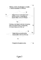
- FIG. 3 illustrates the flow chart of a circuit protection method of the first embodiment of the present invention.
- the circuit protection method of the present invention includes the following steps.
- Step S1 describes the process that a PWM unit 230 detects a plurality of current phases of a plurality of transistors 220 sequentially.
- Step S2 describes the process that the PWM unit 230 determines whether the current phase of each transistor 220 exceeds the corresponding first threshold value or not. If the current phase does not exceed the corresponding first threshold value, then step S 1 repeats.
- step S3 describes the process that the PWM unit 230 produces a control signal to shut down the transistor 220 when the current phase exceeds the corresponding first threshold value.
- the operation of step S3 avoids the excessive current or the overhigh temperature of the transistor 220 such that prevents the PWM unit 230, the transistor 220 or the processor 210 from burning down.
- step S4 executes after shutting down the abnormal transistor 220.
- Step S4 describes the process that the PWM unit 230 judges whether an operation system works normally or not.
- step S 1 If the PWM unit 230 deems that the operation system works normally, step S 1 repeats; otherwise, step S5 follows step S4. Step S5 describes the process that the operation system closes down to inform the user that the circuit board 200 is out of the order and the operation system must close down for repairing.
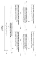
- FIG. 4 illustrates the flow chart of a circuit protection method of the second embodiment of the present invention.
- step S51 follows after shutting down the operation system. Step S51 describes the process that the PWM unit 230 initializes.
- EMI Electromagnetic interference
- ESD Electro-Static discharge
- the PWM unit 230 detects all current phases of the plurality of transistors 220 anew while user reboots the operation system.
- the PWM unit 230 initializes to return the normal operation.
- step S4 if the operation system works normally, step S 1 follows step S4; otherwise, the operation system closes down.
- the PWM unit 230 of the present embodiment examines a plurality of transistors 220 repeatedly and detects each current phase again to make sure whether any abnormal transistor 220 works, then the PWM unit 230 closes down the abnormal transistor 220.
- the PWM unit 230 further determines whether the operation system works normally; if the operation system works normally, step S1 follows; otherwise, the operation system closes down for repairing operation.
- step S51 comes after step S5.
- Step S51 describes the process that the PWM unit 230 initializes.
- the PWM unit 230 detects all current phases of the plurality of transistors 220 anew while user reboots the operation system.
- the PWM unit 230 initializes to return the normal operation.
- Figure 5 illustrates the block chart of the structure of a circuit protection device of the third embodiment of the present invention.
- the present embodiment features, differentiating from the former embodiment, the design further comprising a temperature sensor 240 to detect the temperature of the transistor 220.
- the temperature sensor 240 of the present embodiment could be a thermal resistor, but the temperature sensor 240 is not limited to that described therein.
- the temperature sensor 240 electrically connects to the PWM unit 230 which stores a plurality of second threshold values. Each second threshold value corresponds to the various transistors 220 respectively.
- the PWM unit 230 of the present embodiment receives the temperature information from the temperature sensor 240 and judges whether the temperature of each transistor 220 exceeds the corresponding second threshold value or not. If the temperature of the transistor 220 exceeds the corresponding second threshold value, the transistor 220 is overheated, and then the PWM unit 230 produces a control signal to shut down the transistor 220 when the temperature exceeds the corresponding second threshold value.
- Figure 6 illustrates the flow chart of a circuit protection method of the third embodiment of the present invention.
- the method of the present embodiment further includes the following steps S31, S32 and S33.
- step S31 describes the process that the PWM unit 230 detects a plurality of temperature of a plurality of transistor 220 by receiving the temperature information form the temperature sensor 240.
- step S32 follows step S31, and step S32 describes the process that the PWM unit 230 judges whether the temperature of each transistor 220 exceeds the corresponding second threshold value or not.
- step S33 follows step S32, and step S33 describes the process that the PWM unit 230 produces a control signal to shut down the transistor 220 when the temperature exceeds the corresponding second threshold value.
- the judgment of the current phase and the temperature avoid the excessive current or the overhigh temperature of the transistor 220, such that prevent the PWM unit 230, the transistor 220 or the processor 210 from burning down.
- Figure 7 illustrates the flow chart of a circuit protection method of the fourth embodiment of the present invention.
- the present embodiment features, differentiating from the former embodiments, the design with different sequence of step S31, S32 and S33.
- the third embodiment closes down the abnormal transistor 220 first and then detects the temperature of the transistor 220.
- the present embodiment detects the temperature while the current phase of the transistor 220 is normal. If the current phase of the transistor 220 does not exceed the corresponding first threshold value in step S2, step S31 follows. Consequently, step S32 and step S33 follow step S31 sequentially.
- step S4 follows step S3 and step S33, then step S5 follows step S4. So the step of detecting the temperature of the transistor 220 could precede or succeed the step of monitoring the current phase. Furthermore, the step of detecting the temperature of the transistor 220 could succeed the step of shutting down the abnormal transistor 220. User could regulate the sequence of the steps according to the various requirements.
- the circuit protection device and the circuit protection method of the present invention are implemented by a PWM unit.
- the PWM unit detects a plurality of current phases of a plurality of transistors sequentially, further, the PWM unit determines whether the current phase exceeds the corresponding first threshold value or not, and the PWM unit produces a control signal to shut down the transistor 220 when the current phase exceeds the corresponding first threshold value.
- the present invention avoids the excessive current or the overhigh temperature of the transistor 220, such that prevents the PWM unit 230, the transistor 220 or the processor 210 from burning down.
Landscapes
- Protection Of Static Devices (AREA)
- Emergency Protection Circuit Devices (AREA)
- Semiconductor Integrated Circuits (AREA)
Abstract
Description
- The present invention discloses a circuit protection device and a protection method, in particular, relates to a circuit protection device and a protection method that prevent the transistor from burning down.
- The electrical products prevail in nowadays with the progress in techniques, and most of them are necessary for the daily life, for example, computers, mobile phone or digital players. Many electrical products possess the circuit board with many electrical components, such as processors, transistors, Pulse Width Modulation (PWM) units, capacitance and the like.
- The operation speed of the electrical product increases as the growing requirement. As a result, the temperature of the electrical component increases while higher driving current is required to keep up the speed. For example, a processor, and a transistor which controls power supply, wherein the transistor provides more current to support the processor processing large amount data, such that the temperatures of the processor and the transistor increase.
- Though the promotion of the operation speed of the electrical product increases the temperature of the electrical component, the electrical component, such as processors, transistors, Pulse Width Modulation (PWM) units, capacitance and the like, is not going to overheat or burn down under the normal operation condition.
-
Figure 1 illustrates a circuit board of the prior art. As inFigure 1 , thecircuit board 100 includes aprocessor 110, a plurality oftransistor 120, and a Pulse Width Modulation (PWM)unit 130. ThePWM unit 130 detects the current of thetransistor 120 to measure the current that thetransistor 120 provides for theprocessor 110. Theprocessor 110, thetransistor 120, thePWM unit 130, or other similar electronic component may burn down by the excessive current that results from the aged component, abnormal condition or external effect such as Electromagnetic interference (EMI), Electro-Static discharge (ESD), and so on. - If the
PWM unit 130 or thetransistor 120 becomes abnormal, the current or the temperature of thePWM unit 130 or thetransistor 120 overruns and leads the malfunction of thePWM unit 130 or thetransistor 120. Without any protection mechanism, the electronic component easily bums down or breaks, furthermore, affects the other apparatus. - Accordingly, the present invention provides a circuit protection device and a circuit protection method to solve the aforesaid problems. The circuit protection device and the circuit protection method could keep the transistor from excessive current and overhigh temperature, such that prevent the PWM unit, the transistor or the processor from burning down then solve the problems of the prior art.
- The circuit protection device is applicable to a circuit board and a plurality of transistors are electrically disposed on the circuit board. The circuit protection device includes a Pulse Width Modulation (PWM) unit electrically connecting to the plurality of transistors, and the PWM unit stores a plurality of first threshold values. Each transistor has a current phase and corresponds to the first threshold value. The PWM unit sequentially detects the current phase of each transistor and determines whether the current phase of each transistor exceeds the corresponding first threshold value. Accordingly, the PWM unit produces a control signal to shut down the transistor when the current phase exceeds the corresponding first threshold value.
- The circuit protection method includes the following steps. First, the PWM unit detects a plurality of current phases of a plurality of the plurality of transistors. And the PWM unit determines whether the current phase of each transistor exceeds the corresponding first threshold value, then the PWM unit produces a control signal to shut down the transistor when the current phase exceeds the corresponding first threshold value.
- The features of present invention are to detect the current phase of a transistor and simultaneously judge whether the current phase of each transistor is normal or not. If the current phase is abnormal, the PWM unit shuts down the abnormal transistor. The present invention avoids the excessive current or the overhigh temperature, and as a consequence prevents the PWM unit, the transistor or the processor from burning down.
- Further objects, embodiments and advantages are apparent in the drawings and in the detailed description which follows.
-
-
FIG.1 illustrates the block chart of a circuit board of the prior art. -
FIG.2 illustrates the block chart of a circuit protection device of the first embodiment of the present invention. -
FIG.3 illustrates the flow chart of a circuit protection method of the first embodiment of the present invention. -
FIG.4 illustrates the flow chart of a circuit protection method of the second embodiment of the present invention. -
FIG.5 illustrates the block chart of the structure of a circuit protection device of the third embodiment of the present invention. -
FIG.6 illustrates the flow chart of a circuit protection method of the third embodiment of the present invention. -
FIG.7 illustrates the flow chart of a circuit protection method of the fourth embodiment of the present invention. -
Figure 2 illustrates the block chart of a circuit protection device of the first embodiment of the present invention. The circuit protection device of the present invention is applicable to acircuit board 200 where aprocessor 210 and a plurality oftransistors 220 are disposed, therefore thetransistor 220 provides the current for theprocessor 210. - The circuit protection device of the present invention includes a Pulse Width Modulation (PWM)
unit 230 electrically connecting to the plurality oftransistors 220. Eachtransistor 220 has a current phase. - The
PWM unit 230 stores a plurality of first threshold values, and each first threshold value corresponds to thetransistor 220 respectively. ThePWM unit 230 detects the current phase of eachtransistor 220 in order and judges whether the current phase of eachtransistor 220 exceeds the corresponding first threshold value or not. If the current phase exceeds the corresponding first threshold value, thePWM unit 230 produces a control signal to shut down thetransistor 220 when the current phase exceeds the corresponding first threshold value. - The
PWM unit 230 electrically connects to everytransistor 220 via a plurality of connect lines. ThePWM unit 230 not only detects the current phase of thetransistor 220 but also turns thetransistor 220 on or off. - The
PWM unit 230 of the present invention determines whether the current phase of eachtransistor 220 is normal or not first, and then shuts down theabnormal transistor 220. The operation avoids the excessive current or the overhigh temperature of thetransistor 220, such that prevents thePWM unit 230, thetransistor 220 or theprocessor 210 from burning down. -
Figure 3 illustrates the flow chart of a circuit protection method of the first embodiment of the present invention. The circuit protection method of the present invention includes the following steps. Step S1 describes the process that aPWM unit 230 detects a plurality of current phases of a plurality oftransistors 220 sequentially. Step S2 describes the process that thePWM unit 230 determines whether the current phase of eachtransistor 220 exceeds the corresponding first threshold value or not. If the current phase does not exceed the corresponding first threshold value, then stepS 1 repeats. - If the current phase of each
transistor 220 exceeds the corresponding first threshold value in step S2, step S3 follows step S2. Step S3 describes the process that thePWM unit 230 produces a control signal to shut down thetransistor 220 when the current phase exceeds the corresponding first threshold value. The operation of step S3 avoids the excessive current or the overhigh temperature of thetransistor 220 such that prevents thePWM unit 230, thetransistor 220 or theprocessor 210 from burning down. - In order to avoid the unusual operation of the
circuit board 200, furthermore, to avoid the abnormal operation of the apparatus that utilizes thecircuit board 200, and to avoid the abnormal operation of the operation system of the apparatus then step S4 executes after shutting down theabnormal transistor 220. Step S4 describes the process that thePWM unit 230 judges whether an operation system works normally or not. - If the
PWM unit 230 deems that the operation system works normally, stepS 1 repeats; otherwise, step S5 follows step S4. Step S5 describes the process that the operation system closes down to inform the user that thecircuit board 200 is out of the order and the operation system must close down for repairing. -
Figure 4 illustrates the flow chart of a circuit protection method of the second embodiment of the present invention. For the purpose to prevent thetransistor 220 from being deemed as abnormal and being shut down because of the short interference of the external effects, such as Electromagnetic interference (EMI) or Electro-Static discharge (ESD), step S51 follows after shutting down the operation system. Step S51 describes the process that thePWM unit 230 initializes. - By this way, the
PWM unit 230 detects all current phases of the plurality oftransistors 220 anew while user reboots the operation system. ThePWM unit 230 initializes to return the normal operation. - In addition, after step S4, if the operation system works normally,
step S 1 follows step S4; otherwise, the operation system closes down. - The
PWM unit 230 of the present embodiment examines a plurality oftransistors 220 repeatedly and detects each current phase again to make sure whether anyabnormal transistor 220 works, then thePWM unit 230 closes down theabnormal transistor 220. ThePWM unit 230 further determines whether the operation system works normally; if the operation system works normally, step S1 follows; otherwise, the operation system closes down for repairing operation. - Furthermore, as the step described in
Figure 4 , step S51 comes after step S5. Step S51 describes the process that thePWM unit 230 initializes. ThePWM unit 230 detects all current phases of the plurality oftransistors 220 anew while user reboots the operation system. ThePWM unit 230 initializes to return the normal operation. -
Figure 5 illustrates the block chart of the structure of a circuit protection device of the third embodiment of the present invention. The present embodiment features, differentiating from the former embodiment, the design further comprising atemperature sensor 240 to detect the temperature of thetransistor 220. Thetemperature sensor 240 of the present embodiment could be a thermal resistor, but thetemperature sensor 240 is not limited to that described therein. - The
temperature sensor 240 electrically connects to thePWM unit 230 which stores a plurality of second threshold values. Each second threshold value corresponds to thevarious transistors 220 respectively. - The
PWM unit 230 of the present embodiment receives the temperature information from thetemperature sensor 240 and judges whether the temperature of eachtransistor 220 exceeds the corresponding second threshold value or not. If the temperature of thetransistor 220 exceeds the corresponding second threshold value, thetransistor 220 is overheated, and then thePWM unit 230 produces a control signal to shut down thetransistor 220 when the temperature exceeds the corresponding second threshold value. There is onetemperature sensor 240 of the present embodiment for exemplary description, but the quantity of thetemperature sensor 240 is not limited to that described therein. User could decide the quantity of thetemperature sensor 240 according to various actual designs. -
Figure 6 illustrates the flow chart of a circuit protection method of the third embodiment of the present invention. In order to promote the protection efficiency of thetransistor 220,processor 210 and the like, the method of the present embodiment further includes the following steps S31, S32 and S33. - The
PWM unit 230 detects the temperature after shutting down the transistor when the current phase is abnormal. Consequently, step S31 follows step S3. Step S31 describes the process that thePWM unit 230 detects a plurality of temperature of a plurality oftransistor 220 by receiving the temperature information form thetemperature sensor 240. Step S32 follows step S31, and step S32 describes the process that thePWM unit 230 judges whether the temperature of eachtransistor 220 exceeds the corresponding second threshold value or not. Step S33 follows step S32, and step S33 describes the process that thePWM unit 230 produces a control signal to shut down thetransistor 220 when the temperature exceeds the corresponding second threshold value. - The judgment of the current phase and the temperature avoid the excessive current or the overhigh temperature of the
transistor 220, such that prevent thePWM unit 230, thetransistor 220 or theprocessor 210 from burning down. -
Figure 7 illustrates the flow chart of a circuit protection method of the fourth embodiment of the present invention. The present embodiment features, differentiating from the former embodiments, the design with different sequence of step S31, S32 and S33. - The third embodiment closes down the
abnormal transistor 220 first and then detects the temperature of thetransistor 220. The present embodiment detects the temperature while the current phase of thetransistor 220 is normal. If the current phase of thetransistor 220 does not exceed the corresponding first threshold value in step S2, step S31 follows. Consequently, step S32 and step S33 follow step S31 sequentially. - Moreover, in the present embodiment, step S4 follows step S3 and step S33, then step S5 follows step S4. So the step of detecting the temperature of the
transistor 220 could precede or succeed the step of monitoring the current phase. Furthermore, the step of detecting the temperature of thetransistor 220 could succeed the step of shutting down theabnormal transistor 220. User could regulate the sequence of the steps according to the various requirements. - To sum up, the circuit protection device and the circuit protection method of the present invention are implemented by a PWM unit. The PWM unit detects a plurality of current phases of a plurality of transistors sequentially, further, the PWM unit determines whether the current phase exceeds the corresponding first threshold value or not, and the PWM unit produces a control signal to shut down the
transistor 220 when the current phase exceeds the corresponding first threshold value. The present invention avoids the excessive current or the overhigh temperature of thetransistor 220, such that prevents thePWM unit 230, thetransistor 220 or theprocessor 210 from burning down. - While the disclosure has been described in terms of what is presently consider to be the preferred embodiments, it is to be understood that the disclosure needs not be limited to the disclosed embodiment. On the contrary, it is intended cover various modifications and similar arrangements included within the spirit and scope of the appended claims which are to be accorded with the broadest interpretation so as to encompass all such modification and similar structures. It is therefore intended by the appended claims to define the true scope of the invention.
Claims (9)
- A circuit protection device being applicable to a circuit board (200), a plurality of transistors (220) electrically disposed on the circuit board (200) and each transistor (220) having a current phase respectively, the circuit protection device characterized by comprising:a Pulse Width Modulation (PWM) (230)unit electrically connecting to the transistors (220) and storing a first threshold values corresponding to each of the plurality of transistors (220),wherein the PWM unit (230) detects the current phase of the plurality of transistors (220) in order, determines whether the current phase of each transistor (220) exceeds the corresponding first threshold value, and produces a control signal to shut down the transistor (220) when the current phase thereof exceeds the corresponding first threshold value.
- The circuit protection device as claim 1, further comprising a temperature sensor (240) electrically connecting to the PWM unit (230), wherein the PWM unit (230) further stores a second threshold values corresponding to each of the plurality of transistors (220), detects a temperature of at least one transistor (220), determines whether the temperature exceeds the second threshold value, and generates the control signal to shut down the transistor (220) when the temperature exceeds the second threshold value.
- The circuit protection device as claim 2, wherein the temperature sensor (240) is a thermal resistor.
- A circuit protection method characterized by comprising the following steps:detecting a current phase of a plurality of transistors in order by a PWM unit (230);determining whether the current phase of each transistor (220) exceeds a corresponding first threshold value by the PWM unit (230); andproducing a control signal by the PWM unit (230) to shut down the transistor (220) when the current phase thereof exceeds the corresponding first threshold value.
- The circuit protection method as claim 4, after the step of determining whether the current phase of each transistor (220) exceeds a corresponding first threshold value by the PWM unit (230) and if the current phase does not exceed the corresponding first threshold, further comprising the step of detecting a current phases of a plurality of transistors (220) in order by the PWM unit (230); otherwise, producing a control signal by the PWM unit (230) to shut down the transistor (220) when the current phase exceeds the corresponding first threshold value.
- The circuit protection method as claim 4 characterized by further comprising:shutting down an operation system after the step of producing a control signal by the PWM unit (230) to shut down the transistor (220) when the current phase thereof exceeds the corresponding first threshold value.
- The circuit protection method as claim 6, before the step of shutting down an operation system characterized by further comprising the following step:determining whether the operation system works normally; if not, (further comprising) shutting down the operation system.
- The circuit protection method as claim 6, after the step of shutting down an operation system, further comprising the following step: initializing the PWM unit (230).
- The circuit protection method as claim 4 characterized by further comprising the following step:detecting a temperatures of a plurality of transistors (220) in order by a PWM unit (230);
determining whether the temperature of each transistor (220) exceeds a corresponding second threshold value by the PWM unit (230); and
producing a control signal by the PWM unit (230) to shut down the transistor (220) when the temperature thereof exceeds the corresponding second threshold value.
Applications Claiming Priority (2)
| Application Number | Priority Date | Filing Date | Title |
|---|---|---|---|
| TW100126521A TWI485947B (en) | 2011-07-27 | 2011-07-27 | Circuit protection device and protection method thereof |
| CN201110263786.2A CN102983558B (en) | 2011-07-27 | 2011-09-07 | Circuit protection device and circuit protection method |
Publications (1)
| Publication Number | Publication Date |
|---|---|
| EP2551980A1 true EP2551980A1 (en) | 2013-01-30 |
Family
ID=50158293
Family Applications (1)
| Application Number | Title | Priority Date | Filing Date |
|---|---|---|---|
| EP11190951A Withdrawn EP2551980A1 (en) | 2011-07-27 | 2011-11-28 | Circuit protection device and protection method thereof |
Country Status (5)
| Country | Link |
|---|---|
| US (1) | US8659863B2 (en) |
| EP (1) | EP2551980A1 (en) |
| JP (1) | JP5414817B2 (en) |
| CN (1) | CN102983558B (en) |
| TW (1) | TWI485947B (en) |
Families Citing this family (1)
| Publication number | Priority date | Publication date | Assignee | Title |
|---|---|---|---|---|
| DE102019131499A1 (en) | 2019-11-21 | 2021-05-27 | Carl Freudenberg Kg | Flexible laminate for shielding against electromagnetic radiation |
Citations (3)
| Publication number | Priority date | Publication date | Assignee | Title |
|---|---|---|---|---|
| US4551779A (en) * | 1982-10-12 | 1985-11-05 | Nissan Motor Company, Limited | Semiconductor switching circuit with an overcurrent protection |
| US6335577B1 (en) * | 1999-02-12 | 2002-01-01 | Yazaki Corporation | Power supply control unit and power supply control method |
| CN100517929C (en) * | 2005-12-01 | 2009-07-22 | 技嘉科技股份有限公司 | Multi-phase DC-DC power converter with expansion circuit |
Family Cites Families (7)
| Publication number | Priority date | Publication date | Assignee | Title |
|---|---|---|---|---|
| JPS5967724A (en) * | 1982-10-12 | 1984-04-17 | Nissan Motor Co Ltd | Semiconductor switch circuit |
| JPH04104067A (en) * | 1990-08-24 | 1992-04-06 | Fujitsu Ltd | Power supply circuit |
| US6934139B2 (en) * | 2000-05-01 | 2005-08-23 | Fuji Electric Device Technology Co., Ltd. | Intelligent power module |
| JP2002232280A (en) * | 2001-02-06 | 2002-08-16 | Denso Corp | Load control device |
| JP3846363B2 (en) * | 2002-05-22 | 2006-11-15 | 日本電気株式会社 | Electronic device provided with overvoltage protection circuit, and overvoltage protection circuit and method |
| US7696912B2 (en) * | 2008-05-02 | 2010-04-13 | Exar Corporation | Interrupt based multiplexed current limit circuit |
| US8482256B2 (en) * | 2008-09-11 | 2013-07-09 | Ecosol Technologies Inc. | Portable charging power system for battery-powered devices |
-
2011
- 2011-07-27 TW TW100126521A patent/TWI485947B/en not_active IP Right Cessation
- 2011-09-07 CN CN201110263786.2A patent/CN102983558B/en not_active Expired - Fee Related
- 2011-11-28 EP EP11190951A patent/EP2551980A1/en not_active Withdrawn
- 2011-12-18 US US13/329,312 patent/US8659863B2/en not_active Expired - Fee Related
-
2012
- 2012-02-17 JP JP2012032269A patent/JP5414817B2/en not_active Expired - Fee Related
Patent Citations (3)
| Publication number | Priority date | Publication date | Assignee | Title |
|---|---|---|---|---|
| US4551779A (en) * | 1982-10-12 | 1985-11-05 | Nissan Motor Company, Limited | Semiconductor switching circuit with an overcurrent protection |
| US6335577B1 (en) * | 1999-02-12 | 2002-01-01 | Yazaki Corporation | Power supply control unit and power supply control method |
| CN100517929C (en) * | 2005-12-01 | 2009-07-22 | 技嘉科技股份有限公司 | Multi-phase DC-DC power converter with expansion circuit |
Also Published As
| Publication number | Publication date |
|---|---|
| US20130027826A1 (en) | 2013-01-31 |
| TWI485947B (en) | 2015-05-21 |
| CN102983558A (en) | 2013-03-20 |
| US8659863B2 (en) | 2014-02-25 |
| CN102983558B (en) | 2017-05-24 |
| TW201306413A (en) | 2013-02-01 |
| JP5414817B2 (en) | 2014-02-12 |
| JP2013031354A (en) | 2013-02-07 |
Similar Documents
| Publication | Publication Date | Title |
|---|---|---|
| US8671290B2 (en) | Heat dissipating device | |
| CN109441864A (en) | A kind of server fan control method, device, equipment and computer storage medium | |
| US20130208419A1 (en) | Temperature control system | |
| CN102955718B (en) | Server protection system | |
| US9712104B2 (en) | Control method of over-temperature protection, driver chip and control system of over-temperature protection | |
| US10018202B1 (en) | Fan control system | |
| CN110701084B (en) | Fan control method in electronic system | |
| US9735563B2 (en) | Power distribution method, power distribution apparatus, and information handling system | |
| CN104699215A (en) | Power supply protection system and power supply protection method | |
| CN108836138A (en) | A kind of motor protection method of food processor | |
| CN204732852U (en) | Domestic food system of processing and electric motor protective device thereof | |
| US8782444B2 (en) | Circuit protection system and method for a circuit utilizing chip type power supply | |
| US9382915B2 (en) | Control method of fan rotation speed | |
| CN103821746A (en) | Fan monitoring method and sever system | |
| US8659863B2 (en) | Circuit protection device and protection method thereof | |
| JP2009217776A (en) | Information processor | |
| US7458781B2 (en) | Radiation fan driving apparatus | |
| JP2016182009A (en) | Power supply device and image forming apparatus including power supply device | |
| CN102810840B (en) | Voltage protection system | |
| JP2015175239A (en) | Monitoring device, monitoring method, and program | |
| US20150032284A1 (en) | Detection module, device and system for detecting fan's connection and disconnection states | |
| US20130293033A1 (en) | Method of controlling a power feed and apparatus | |
| TWI487844B (en) | Method for fan monitoring and server system using the same | |
| JP5407466B2 (en) | Power control method | |
| EP1440378B1 (en) | In-rush current controller |
Legal Events
| Date | Code | Title | Description |
|---|---|---|---|
| PUAI | Public reference made under article 153(3) epc to a published international application that has entered the european phase |
Free format text: ORIGINAL CODE: 0009012 |
|
| AK | Designated contracting states |
Kind code of ref document: A1 Designated state(s): AL AT BE BG CH CY CZ DE DK EE ES FI FR GB GR HR HU IE IS IT LI LT LU LV MC MK MT NL NO PL PT RO RS SE SI SK SM TR |
|
| AX | Request for extension of the european patent |
Extension state: BA ME |
|
| 17P | Request for examination filed |
Effective date: 20130113 |
|
| RAP1 | Party data changed (applicant data changed or rights of an application transferred) |
Owner name: GIGA-BYTE TECHNOLOGY CO., LTD. |
|
| 17Q | First examination report despatched |
Effective date: 20140515 |
|
| STAA | Information on the status of an ep patent application or granted ep patent |
Free format text: STATUS: THE APPLICATION IS DEEMED TO BE WITHDRAWN |
|
| 18D | Application deemed to be withdrawn |
Effective date: 20140926 |