EP2551870A1 - Electromagnetic relay - Google Patents
Electromagnetic relay Download PDFInfo
- Publication number
- EP2551870A1 EP2551870A1 EP12175519A EP12175519A EP2551870A1 EP 2551870 A1 EP2551870 A1 EP 2551870A1 EP 12175519 A EP12175519 A EP 12175519A EP 12175519 A EP12175519 A EP 12175519A EP 2551870 A1 EP2551870 A1 EP 2551870A1
- Authority
- EP
- European Patent Office
- Prior art keywords
- armature
- contact point
- card
- electromagnet
- connector piece
- Prior art date
- Legal status (The legal status is an assumption and is not a legal conclusion. Google has not performed a legal analysis and makes no representation as to the accuracy of the status listed.)
- Granted
Links
- 239000000696 magnetic material Substances 0.000 claims abstract description 8
- 239000000463 material Substances 0.000 claims abstract description 5
- 238000006073 displacement reaction Methods 0.000 claims description 4
- 238000000034 method Methods 0.000 description 4
- 230000005489 elastic deformation Effects 0.000 description 2
- 238000003860 storage Methods 0.000 description 2
- 229910052782 aluminium Inorganic materials 0.000 description 1
- XAGFODPZIPBFFR-UHFFFAOYSA-N aluminium Chemical compound [Al] XAGFODPZIPBFFR-UHFFFAOYSA-N 0.000 description 1
- 230000000052 comparative effect Effects 0.000 description 1
- 238000005304 joining Methods 0.000 description 1
- 229910052751 metal Inorganic materials 0.000 description 1
- 239000002184 metal Substances 0.000 description 1
- 238000012986 modification Methods 0.000 description 1
- 230000004048 modification Effects 0.000 description 1
- 238000003825 pressing Methods 0.000 description 1
- 229920003002 synthetic resin Polymers 0.000 description 1
- 239000000057 synthetic resin Substances 0.000 description 1
- 230000007704 transition Effects 0.000 description 1
- 238000003466 welding Methods 0.000 description 1
Images


Classifications
-
- H—ELECTRICITY
- H01—ELECTRIC ELEMENTS
- H01H—ELECTRIC SWITCHES; RELAYS; SELECTORS; EMERGENCY PROTECTIVE DEVICES
- H01H1/00—Contacts
- H01H1/12—Contacts characterised by the manner in which co-operating contacts engage
- H01H1/14—Contacts characterised by the manner in which co-operating contacts engage by abutting
- H01H1/34—Contacts characterised by the manner in which co-operating contacts engage by abutting with provision for adjusting position of contact relative to its co-operating contact
-
- H—ELECTRICITY
- H01—ELECTRIC ELEMENTS
- H01H—ELECTRIC SWITCHES; RELAYS; SELECTORS; EMERGENCY PROTECTIVE DEVICES
- H01H50/00—Details of electromagnetic relays
- H01H50/64—Driving arrangements between movable part of magnetic circuit and contact
- H01H50/641—Driving arrangements between movable part of magnetic circuit and contact intermediate part performing a rectilinear movement
- H01H50/642—Driving arrangements between movable part of magnetic circuit and contact intermediate part performing a rectilinear movement intermediate part being generally a slide plate, e.g. a card
-
- H—ELECTRICITY
- H01—ELECTRIC ELEMENTS
- H01H—ELECTRIC SWITCHES; RELAYS; SELECTORS; EMERGENCY PROTECTIVE DEVICES
- H01H51/00—Electromagnetic relays
- H01H51/22—Polarised relays
- H01H51/2227—Polarised relays in which the movable part comprises at least one permanent magnet, sandwiched between pole-plates, each forming an active air-gap with parts of the stationary magnetic circuit
-
- H—ELECTRICITY
- H01—ELECTRIC ELEMENTS
- H01H—ELECTRIC SWITCHES; RELAYS; SELECTORS; EMERGENCY PROTECTIVE DEVICES
- H01H69/00—Apparatus or processes for the manufacture of emergency protective devices
- H01H69/01—Apparatus or processes for the manufacture of emergency protective devices for calibrating or setting of devices to function under predetermined conditions
-
- H—ELECTRICITY
- H01—ELECTRIC ELEMENTS
- H01H—ELECTRIC SWITCHES; RELAYS; SELECTORS; EMERGENCY PROTECTIVE DEVICES
- H01H11/00—Apparatus or processes specially adapted for the manufacture of electric switches
- H01H2011/0075—Apparatus or processes specially adapted for the manufacture of electric switches calibrating mechanical switching properties, e.g. "snap or switch moment", by mechanically deforming a part of the switch, e.g. elongating a blade spring by puncturing it with a laser
-
- H—ELECTRICITY
- H01—ELECTRIC ELEMENTS
- H01H—ELECTRIC SWITCHES; RELAYS; SELECTORS; EMERGENCY PROTECTIVE DEVICES
- H01H51/00—Electromagnetic relays
- H01H51/22—Polarised relays
- H01H51/2272—Polarised relays comprising rockable armature, rocking movement around central axis parallel to the main plane of the armature
Definitions
- the present invention relates to an electromagnetic relay.
- the electromagnetic relay shown in Fig. 3 includes an electromagnet 1, an armature 2 rotationally driven by the magnetic force of the electromagnet 1 and a housing 3 for storing the electromagnet 1 and the armature 2.
- the electromagnet 1 is fixed to the housing 3.
- the upper, lower, left and right sides will be defined on the basis of Fig. 3 .
- the front side of the drawing sheet in Fig. 3 will be called "front side".
- these directions are defined just for the sake of convenience in description and may not conform to the directions under an actual use condition.
- the housing 3 includes a body 31 having a storage recess 30 whose front side is opened and a cover (not shown) coupled to the front side of the body 31 to close the storage recess 30.
- a support body 4 for rotatably supporting the armature 2 with respect to the housing 3 is fixed to the housing 3.
- the support body 4 includes a flat fixing portion 41 whose thickness direction extends in the front-rear direction and whose left-right end portions are fixed to the body 31 and a cylindrical shaft portion 42 protruding frontward from a central area of a front surface of the fixing portion 41.
- the axial direction of the shaft portion 42 extends in the front-rear direction.
- the armature 2 has a bearing hole 20 with a circular cross section. The bearing hole 20 extends through the armature 2 in the front-rear direction.
- the inner diameter of the bearing hole 20 is a little larger than the outer diameter of the shaft portion 42.
- the shaft portion 42 is inserted into the bearing hole 20, whereby the armature 2 is supported with respect to the housing 3 so as to rotate about the center axis of the shaft portion 42.
- the electromagnet 1 includes a coil (not shown) fixed to the body 31 at the rear side of the fixing portion 41 such that the axial direction thereof extends in the up-down direction and a magnetic pole piece 11 made of a magnetic material and magnetized by the coil.
- the magnetic pole piece 11 includes a body portion (not shown) extending through the coil in the up-down direction and variable magnetic pole portions 11a protruding frontward from the upper and lower ends of the body portion.
- the magnetic pole piece 11 has a generally U-like shape as a whole. More specifically, the variable magnetic pole portions 11a are magnetized into different polarities depending on the flow direction of a current supplied to the coil. The polarities of the variable magnetic pole portions 11a differ from each other.
- coil terminals 60 are held in the housing 3.
- the coil terminals.60 are electrically connected to the coil at one ends thereof.
- the other ends of the coil terminals 60 protrude toward the left side of the housing 3.
- An electric current is fed to the coil through the coil terminals 60.
- the electromagnetic relay shown in Fig. 3 is of a so-called two-coil latch type.
- the coil is provided with a tap.
- the coil terminals 60 are electrically connected to the opposite ends and the tap of the coil.
- the armature 2 includes two pairs of fixed magnetic pole portions 21a which are respectively provided at the upper and lower end portions thereof. Each of the variable magnetic pole portions 11a is interposed between each pair of the fixed magnetic pole portions 21a. In each pair of the fixed magnetic pole portions 21a, the fixed magnetic pole portion 21a existing at the left side of the variable magnetic pole portions 11a and the fixed magnetic pole portion 21a existing at the right side of the variable magnetic pole portions 11a are magnetized with different polarities. More specifically, the armature 2 includes two permanent magnets 22 whose N-poles are oriented in the same left or right direction, two armature members 21 made of a magnetic material and a synthetic-resin molded body 23 with which the permanent magnets 22 and the armature members 21 are insert-molded.
- Each of the armature members 21 has a flat rectangular parallelepiped shape. One thickness-direction surface of each of the armature members 21 is magnetically attached to the pole of each of the permanent magnets 22. The opposite end portions of each of the armature members 21 protruding upward and downward beyond each of the permanent magnets 22 serve as the fixed magnetic pole portions 21a. If an electric current is supplied to the coil of the electromagnet 1, one of the fixed magnetic pole portions 21a existing at the left and right sides of the corresponding variable magnetic pole portion 11a is attracted to the corresponding variable magnetic pole portion 11a depending on the direction of the electric current flowing through the coil, whereby the armature 2 is rotated with respect to the housing 3.
- a movable contact point 51 moving together with the rotation of the armature 2 and a fixed contact point 52 coming into contact with or out of contact with the movable contact point 51 are stored within the housing 3.
- the movable contact point 51 and the fixed contact point 52 are electrically connected to terminal plates 61 and 62, respectively.
- the electric connection between the terminal plates 61 and 62 is switched on and off as the movable contact point 51 comes into contact with or out of contact with the movable contact point 51.
- Each of the terminal plates 61 and 62 is formed of a metal plate with the thickness direction thereof extending in the left-right direction.
- Each of the terminal plates 61 and 62 is fixed to the housing 3 in such a fashion that the upper end portion thereof protrudes outside the housing 3.
- the movable contact point 51 is electrically and mechanically connected to the terminal plate 61 through a contact point retainer 7.
- the lower end portion of the contact point retainer 7 is fixed to a right surface of the terminal plate 61 and the upper end portion of the contact point retainer 7 is elastically deformable to be displaced in the left-right direction with respect to the lower end portion of the contact point retainer 7.
- the contact point retainer 7 includes a plurality of contact point retaining springs 71, each of which is formed of a leaf spring extending in the up-down direction.
- the contact point retaining springs 71 are superimposed in the thickness direction and are bonded to one another in the upper end portions and the lower end portions thereof.
- the movable contact point 51 is fixed to the upper end portion of the contact point retainer 7, so that the movable contact point 51 can be elastically displaced in the left-right direction with respect to the housing 3 at the left side of the fixed contact point 52.
- the armature 2 and the movable contact point 51 are moved together by a card 8 connected to the contact point retainer 7 and the armature 2.
- the card 8 has a flat shape as a whole with the thickness direction thereof extending in the up-down direction.
- the card 8 is guided by the inner surface of the housing 3 so that the card 8 can move in the left-right direction with respect to the housing 3.
- the terminal plate 61 connected to the movable contact point 51 is shaped not to interfere with the moving path of the card 8 so that the terminal plate 61 should not hinder the displacement of the card 8.
- the armature 2 and the card 8 are connected to each other by inserting the upper end portion of the right armature member 21 of the armature 2 into an armature recess portion 81 of the card 8 opened upward, downward and frontward.
- the contact point retainer 7 and the card 8 are connected to each other by inserting the upper end portion of the contact point retainer 7 into a retainer recess portion (not shown) of the card 8 opened upward, downward and rearward.
- an elastic card contact portion 72 making contact with the inner surface of the retainer recess portion facing rightward.
- the elastic card contact portion 72 is inclined so as to extend gradually away from the remaining contact point retaining springs 71.
- the portion of the armature 2 connected to the card 8 is the armature member 21.
- the armature member 21 is formed relatively thick in order to sufficiently increase the magnetic force. Therefore, it is considerably difficult to adjust the operation characteristics by using the method stated above.
- the present invention provides an electromagnetic relay whose operation characteristics can be adjusted with ease.
- an electromagnetic relay including: an electromagnet; an armature driven by a magnetic force of the electromagnet and configured to rotate with respect to the electromagnet; a card configured to linearly move when pressed by the armature; a movable contact point moving together with the card; a fixed contact point with which the movable contact point comes into contact or out of contact in response to rotation of the armature; and a housing for storing the electromagnet, the armature, the card, the movable contact point and the fixed contact point, the electromagnet and the fixed contact point being fixed to the housing, wherein the armature includes at least one armature member made of a magnetic material and a connector piece made of a plastically deformable material, the connector piece being arranged between the armature member and the card.
- the connector piece may be bent such that, when seen in a direction parallel to a rotation axis of the armature, the angle formed by a line, which interconnects a contact position of the armature with the card and the rotation axis of the armature, with respect to a displacement direction of the card gets closer to a right angle.
- the connector piece may be made of a non-magnetic material.
- the operation characteristics can be adjusted by plastically deforming a connector piece which is not required to secure a magnetic property and which is more readily deformed than the armature member. It is therefore easy to adjust the operation characteristics of the electromagnetic relay as compared with a case where the armature member makes direct contact with the card.
- the basic configuration of the present embodiment is essentially the same as that of the example shown in Fig. 3 . No description will be made on the common components.
- the armature 2 includes a connector piece 24 connected to the right armature member 21 and protruding upward beyond the right armature member 21.
- the connector piece 24 is inserted into the armature recess portion 81 of the card 8.
- the connector piece 24 is made of a plastically deformable material.
- the connector piece 24 is formed into a flat shape to have a thickness smaller than the thickness of the armature member 21.
- the thickness direction of the connector piece 24 is orthogonal to the rotation axis of the armature 2.
- the connector piece 24 and the armature member 21 together it is possible to appropriately use a well-known method such as caulking, fitting or welding.
- a well-known method such as caulking, fitting or welding.
- the material of the connector piece 24 it is preferable to use a non-magnetic material, e.g., aluminum.
- the operation characteristics of the electromagnetic relay can be adjusted by plastically deforming the connector piece 24 which is smaller in thickness than the armature member 21 and which can be more readily deformed than the armature member 21. It is therefore easy to adjust the operation characteristics as compared with a case where the armature member 21 is inserted into the armature recess portion 81 of the card 8.
- the deformation amount of the elastic card contact portion 72 grows larger in the closed state. This makes it possible to obtain an increased contact pressure.
- the deformation amount of the contact point retainer 7 as a whole grows smaller in the open state. Thus the minimum on-current becomes higher.
- the deformation amount of the elastic card contact portion 72 grows smaller in the closed state. This makes it possible to reduce the contact pressure.
- the deformation amount of the contact point retainer 7 as a whole grows larger in the open state. Thus the minimum on-current becomes lower.
- the connector piece 24 is bent to ensure that the drive angle gets closer to 90 degrees. More specifically, since the rotation axis of the armature 2 (i.e., the center axis of the shaft portion 42) is positioned at the left side of the moving range of the armature recess portion 81, the connector piece 24 is bent into a generally S-like shape so that the end portion thereof existing near the card 8 can be positioned at the left side of the end portion existing near the armature member 21. Accordingly, as compared with a case where the connector piece 24 is not bent as shown in Fig. 2 , it is possible to reduce the frictional force acting between the connector piece 24 and the card 8 or between the card 8 and the inner surface of the housing 3. This makes it possible to reduce the electric power required in opening and closing the contact points.
- an additional member may be arranged between the connector piece 24 and the card 8 or between the armature member 21 and the connector piece 24.
Landscapes
- Physics & Mathematics (AREA)
- Electromagnetism (AREA)
- Engineering & Computer Science (AREA)
- Manufacturing & Machinery (AREA)
- Electromagnets (AREA)
- Telephone Set Structure (AREA)
Abstract
Description
- The present invention relates to an electromagnetic relay.
- Conventionally, there is available an electromagnetic relay that brings a movable contact point into contact with or out of contact with a fixed contact point by rotationally driving an armature connected to the movable contact point through the use of a magnetic force of an electromagnet (see, e.g., Japanese Utility Model Application Publication No.
H4-24242 - As the electromagnetic relay of this kind, there is known, e.g., an electromagnetic relay shown in
Fig. 3 . - The electromagnetic relay shown in
Fig. 3 will now be described in detail. The electromagnetic relay shown inFig. 3 includes anelectromagnet 1, anarmature 2 rotationally driven by the magnetic force of theelectromagnet 1 and ahousing 3 for storing theelectromagnet 1 and thearmature 2. Theelectromagnet 1 is fixed to thehousing 3. In the following description, the upper, lower, left and right sides will be defined on the basis ofFig. 3 . The front side of the drawing sheet inFig. 3 will be called "front side". However, these directions are defined just for the sake of convenience in description and may not conform to the directions under an actual use condition. - The
housing 3 includes abody 31 having astorage recess 30 whose front side is opened and a cover (not shown) coupled to the front side of thebody 31 to close thestorage recess 30. - A
support body 4 for rotatably supporting thearmature 2 with respect to thehousing 3 is fixed to thehousing 3. Thesupport body 4 includes aflat fixing portion 41 whose thickness direction extends in the front-rear direction and whose left-right end portions are fixed to thebody 31 and acylindrical shaft portion 42 protruding frontward from a central area of a front surface of thefixing portion 41. The axial direction of theshaft portion 42 extends in the front-rear direction. As a means for fixing thefixing portion 41 to thebody 31, it is possible to use a well-known means such as fitting or the like. Thearmature 2 has abearing hole 20 with a circular cross section. Thebearing hole 20 extends through thearmature 2 in the front-rear direction. The inner diameter of thebearing hole 20 is a little larger than the outer diameter of theshaft portion 42. Theshaft portion 42 is inserted into thebearing hole 20, whereby thearmature 2 is supported with respect to thehousing 3 so as to rotate about the center axis of theshaft portion 42. - The
electromagnet 1 includes a coil (not shown) fixed to thebody 31 at the rear side of thefixing portion 41 such that the axial direction thereof extends in the up-down direction and amagnetic pole piece 11 made of a magnetic material and magnetized by the coil. Themagnetic pole piece 11 includes a body portion (not shown) extending through the coil in the up-down direction and variablemagnetic pole portions 11a protruding frontward from the upper and lower ends of the body portion. Thus, themagnetic pole piece 11 has a generally U-like shape as a whole. More specifically, the variablemagnetic pole portions 11a are magnetized into different polarities depending on the flow direction of a current supplied to the coil. The polarities of the variablemagnetic pole portions 11a differ from each other. A plurality of (three, inFig. 3 )coil terminals 60 are held in thehousing 3. The coil terminals.60 are electrically connected to the coil at one ends thereof. The other ends of thecoil terminals 60 protrude toward the left side of thehousing 3. An electric current is fed to the coil through thecoil terminals 60. More specifically, the electromagnetic relay shown inFig. 3 is of a so-called two-coil latch type. The coil is provided with a tap. Thecoil terminals 60 are electrically connected to the opposite ends and the tap of the coil. - The
armature 2 includes two pairs of fixedmagnetic pole portions 21a which are respectively provided at the upper and lower end portions thereof. Each of the variablemagnetic pole portions 11a is interposed between each pair of the fixedmagnetic pole portions 21a. In each pair of the fixedmagnetic pole portions 21a, the fixedmagnetic pole portion 21a existing at the left side of the variablemagnetic pole portions 11a and the fixedmagnetic pole portion 21a existing at the right side of the variablemagnetic pole portions 11a are magnetized with different polarities. More specifically, thearmature 2 includes twopermanent magnets 22 whose N-poles are oriented in the same left or right direction, twoarmature members 21 made of a magnetic material and a synthetic-resin moldedbody 23 with which thepermanent magnets 22 and thearmature members 21 are insert-molded. Each of thearmature members 21 has a flat rectangular parallelepiped shape. One thickness-direction surface of each of thearmature members 21 is magnetically attached to the pole of each of thepermanent magnets 22. The opposite end portions of each of thearmature members 21 protruding upward and downward beyond each of thepermanent magnets 22 serve as the fixedmagnetic pole portions 21a. If an electric current is supplied to the coil of theelectromagnet 1, one of the fixedmagnetic pole portions 21a existing at the left and right sides of the corresponding variablemagnetic pole portion 11a is attracted to the corresponding variablemagnetic pole portion 11a depending on the direction of the electric current flowing through the coil, whereby thearmature 2 is rotated with respect to thehousing 3. Once the electric current is supplied to the coil, the position of the armature 2 (and the position of themovable contact point 51 moving together with the armature 2) is maintained (latched) by the magnetic force of thepermanent magnets 22 until an electric current flows through the coil in the reverse direction. - A
movable contact point 51 moving together with the rotation of thearmature 2 and afixed contact point 52 coming into contact with or out of contact with themovable contact point 51 are stored within thehousing 3. Themovable contact point 51 and thefixed contact point 52 are electrically connected toterminal plates terminal plates movable contact point 51 comes into contact with or out of contact with themovable contact point 51. Each of theterminal plates terminal plates housing 3 in such a fashion that the upper end portion thereof protrudes outside thehousing 3. Themovable contact point 51 is electrically and mechanically connected to theterminal plate 61 through acontact point retainer 7. The lower end portion of thecontact point retainer 7 is fixed to a right surface of theterminal plate 61 and the upper end portion of thecontact point retainer 7 is elastically deformable to be displaced in the left-right direction with respect to the lower end portion of thecontact point retainer 7. Thecontact point retainer 7 includes a plurality of contact point retainingsprings 71, each of which is formed of a leaf spring extending in the up-down direction. The contact point retainingsprings 71 are superimposed in the thickness direction and are bonded to one another in the upper end portions and the lower end portions thereof. Themovable contact point 51 is fixed to the upper end portion of thecontact point retainer 7, so that themovable contact point 51 can be elastically displaced in the left-right direction with respect to thehousing 3 at the left side of thefixed contact point 52. - The
armature 2 and themovable contact point 51 are moved together by acard 8 connected to thecontact point retainer 7 and thearmature 2. Thecard 8 has a flat shape as a whole with the thickness direction thereof extending in the up-down direction. Thecard 8 is guided by the inner surface of thehousing 3 so that thecard 8 can move in the left-right direction with respect to thehousing 3. Theterminal plate 61 connected to themovable contact point 51 is shaped not to interfere with the moving path of thecard 8 so that theterminal plate 61 should not hinder the displacement of thecard 8. Thearmature 2 and thecard 8 are connected to each other by inserting the upper end portion of theright armature member 21 of thearmature 2 into an armature recessportion 81 of thecard 8 opened upward, downward and frontward. Thecontact point retainer 7 and thecard 8 are connected to each other by inserting the upper end portion of thecontact point retainer 7 into a retainer recess portion (not shown) of thecard 8 opened upward, downward and rearward. In the upper end portion of the leftmost one of the contact point retainingsprings 71, there is provided an elasticcard contact portion 72 making contact with the inner surface of the retainer recess portion facing rightward. The elasticcard contact portion 72 is inclined so as to extend gradually away from the remaining contact point retainingsprings 71. - In a state that the
armature 2 is rotated clockwise to the limit of a moving range with themovable contact point 51 making contact with the fixed contact point 52 (hereinafter referred to as "closed state"), a contact pressure is generated between themovable contact point 51 and thefixed contact point 52 due to the elastic deformation of the elasticcard contact portion 72. - In a state that, as shown in
Fig. 3 , thearmature 2 is rotated counterclockwise to the limit of the moving range with themovable contact point 51 kept out of contact with the fixed contact point 52 (hereinafter referred to as "open state"), thecontact point retainer 7 as a whole is elastically deformed so that the upper end portion thereof is displaced leftward with respect to the lower end portion. At this time, the spring force of thecontact point retainer 7 acts to bias themovable contact point 51 toward thefixed contact point 52. In other words, the minimum value of an electric current flowing through the coil of theelectromagnet 1 required to the transition to the closed state (hereinafter referred to as "minimum on-current") becomes smaller as the elastic deformation amount grows larger. - In this regard, as a method of adjusting the operation characteristics (e.g., the minimum on-current or the contact pressure in the closed state), it is thinkable to use a method of plastically deforming the portion of the
armature 2 connected to thecard 8. - In the example described above, however, the portion of the
armature 2 connected to thecard 8 is thearmature member 21. Thearmature member 21 is formed relatively thick in order to sufficiently increase the magnetic force. Therefore, it is considerably difficult to adjust the operation characteristics by using the method stated above. - In view of the above, the present invention provides an electromagnetic relay whose operation characteristics can be adjusted with ease.
- In accordance with one aspect of the present invention, there is provided an electromagnetic relay, including: an electromagnet; an armature driven by a magnetic force of the electromagnet and configured to rotate with respect to the electromagnet; a card configured to linearly move when pressed by the armature; a movable contact point moving together with the card; a fixed contact point with which the movable contact point comes into contact or out of contact in response to rotation of the armature; and a housing for storing the electromagnet, the armature, the card, the movable contact point and the fixed contact point, the electromagnet and the fixed contact point being fixed to the housing, wherein the armature includes at least one armature member made of a magnetic material and a connector piece made of a plastically deformable material, the connector piece being arranged between the armature member and the card.
- Preferably, the connector piece may be bent such that, when seen in a direction parallel to a rotation axis of the armature, the angle formed by a line, which interconnects a contact position of the armature with the card and the rotation axis of the armature, with respect to a displacement direction of the card gets closer to a right angle.
- Preferably, the connector piece may be made of a non-magnetic material.
- With the present embodiment, the operation characteristics can be adjusted by plastically deforming a connector piece which is not required to secure a magnetic property and which is more readily deformed than the armature member. It is therefore easy to adjust the operation characteristics of the electromagnetic relay as compared with a case where the armature member makes direct contact with the card.
-
-
Fig. 1 is a front view showing an electromagnetic relay according to one embodiment of the present invention, with a cover removed for clarity. -
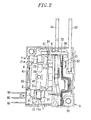
Fig. 2 is a front view showing a comparative example of the electromagnetic relay, with a cover removed for clarity. -
Fig. 3 is a front view showing a conventional electromagnetic relay, with a cover removed for clarity. - One preferred embodiment of the present invention will now be described in detail with reference to the accompanying drawings which form a part hereof.
- The basic configuration of the present embodiment is essentially the same as that of the example shown in
Fig. 3 . No description will be made on the common components. - In the present embodiment, as shown in
Fig. 1 , thearmature 2 includes aconnector piece 24 connected to theright armature member 21 and protruding upward beyond theright armature member 21. Theconnector piece 24 is inserted into thearmature recess portion 81 of thecard 8. Theconnector piece 24 is made of a plastically deformable material. Theconnector piece 24 is formed into a flat shape to have a thickness smaller than the thickness of thearmature member 21. The thickness direction of theconnector piece 24 is orthogonal to the rotation axis of thearmature 2. - As a means for joining the
connector piece 24 and thearmature member 21 together, it is possible to appropriately use a well-known method such as caulking, fitting or welding. As the material of theconnector piece 24, it is preferable to use a non-magnetic material, e.g., aluminum. - With the configuration stated above, the operation characteristics of the electromagnetic relay can be adjusted by plastically deforming the
connector piece 24 which is smaller in thickness than thearmature member 21 and which can be more readily deformed than thearmature member 21. It is therefore easy to adjust the operation characteristics as compared with a case where thearmature member 21 is inserted into thearmature recess portion 81 of thecard 8. - For example, if the
connector piece 24 is bent to move thecard 8 rightward (namely, if the upper end portion of theconnector piece 24 is displaced rightward with respect to the lower end portion thereof), the deformation amount of the elasticcard contact portion 72 grows larger in the closed state. This makes it possible to obtain an increased contact pressure. On the other hand, the deformation amount of thecontact point retainer 7 as a whole grows smaller in the open state. Thus the minimum on-current becomes higher. - On the contrary, if the
connector piece 24 is bent to move thecard 8 leftward (namely, if the upper end portion of theconnector piece 24 is displaced leftward with respect to the lower end portion thereof), the deformation amount of the elasticcard contact portion 72 grows smaller in the closed state. This makes it possible to reduce the contact pressure. On the other hand, the deformation amount of thecontact point retainer 7 as a whole grows larger in the open state. Thus the minimum on-current becomes lower. - When seen from the front side, i.e., in the direction parallel to the rotation axis of the
armature 2, if the difference between the right angle (90 degrees) and the angle (hereinafter referred to as "drive angle") formed by a line, which interconnects the contact position of the armature 2 (the connector piece 24) with thecard 8 and the rotation axis of thearmature 2, with respect to a displacement direction of thecard 8 becomes greater, the component force of the rotational force of thearmature 2 acting as a push force pressing thecard 8 upward or downward grows larger. If the component force grows larger, the frictional force acting between theconnector piece 24 and thecard 8 or between thecard 8 and the inner surface of thehousing 3 becomes greater. This increases the drive force (the electric power inputted to the electromagnet 1) which is required to switch the on-off state of the contact points. - In the example shown in
Fig. 1 , theconnector piece 24 is bent to ensure that the drive angle gets closer to 90 degrees. More specifically, since the rotation axis of the armature 2 (i.e., the center axis of the shaft portion 42) is positioned at the left side of the moving range of thearmature recess portion 81, theconnector piece 24 is bent into a generally S-like shape so that the end portion thereof existing near thecard 8 can be positioned at the left side of the end portion existing near thearmature member 21. Accordingly, as compared with a case where theconnector piece 24 is not bent as shown inFig. 2 , it is possible to reduce the frictional force acting between theconnector piece 24 and thecard 8 or between thecard 8 and the inner surface of thehousing 3. This makes it possible to reduce the electric power required in opening and closing the contact points. - Instead of bringing the
connector piece 24 into direct contact with thearmature member 21 and thecard 8 as set forth above, an additional member may be arranged between theconnector piece 24 and thecard 8 or between thearmature member 21 and theconnector piece 24. - While the invention has been shown and described with respect to the embodiments, the present invention is not limited thereto. It will be understood by those skilled in the art that various changes and modifications may be made without departing from the scope of the invention as defined in the following claims.
Claims (3)
- An electromagnetic relay, comprising:an electromagnet;an armature driven by a magnetic force of the electromagnet and configured to rotate with respect to the electromagnet;a card configured to linearly move when pressed by the armature;a movable contact point moving together with the card;a fixed contact point with which the movable contact point comes into contact or out of contact in response to rotation of the armature; anda housing for storing the electromagnet, the armature, the card, the movable contact point and the fixed contact point, the electromagnet and the fixed contact point being fixed to the housing,wherein the armature includes at least one armature member made of a magnetic material and a connector piece made of a plastically deformable material, the connector piece being arranged between the armature member and the card.
- The relay of claim 1, wherein the connector piece is bent such that, when seen in a direction parallel to a rotation axis of the armature, the angle formed by a line, which interconnects a contact position of the armature with the card and the rotation axis of the armature, with respect to a displacement direction of the card gets closer to a right angle.
- The relay of claim 1 or 2, wherein the connector piece is made of a non-magnetic material.
Applications Claiming Priority (1)
| Application Number | Priority Date | Filing Date | Title |
|---|---|---|---|
| JP2011164191A JP5821030B2 (en) | 2011-07-27 | 2011-07-27 | Electromagnetic relay |
Publications (2)
| Publication Number | Publication Date |
|---|---|
| EP2551870A1 true EP2551870A1 (en) | 2013-01-30 |
| EP2551870B1 EP2551870B1 (en) | 2014-01-29 |
Family
ID=46650361
Family Applications (1)
| Application Number | Title | Priority Date | Filing Date |
|---|---|---|---|
| EP20120175519 Active EP2551870B1 (en) | 2011-07-27 | 2012-07-09 | Electromagnetic relay |
Country Status (4)
| Country | Link |
|---|---|
| EP (1) | EP2551870B1 (en) |
| JP (1) | JP5821030B2 (en) |
| CN (1) | CN102903574B (en) |
| ES (1) | ES2445806T3 (en) |
Cited By (2)
| Publication number | Priority date | Publication date | Assignee | Title |
|---|---|---|---|---|
| GB2511569A (en) * | 2013-03-08 | 2014-09-10 | Christopher John Stanton | Improved switch and associated methods |
| EP2945175A1 (en) * | 2014-05-12 | 2015-11-18 | Panasonic Intellectual Property Management Co., Ltd. | Contact device |
Families Citing this family (5)
| Publication number | Priority date | Publication date | Assignee | Title |
|---|---|---|---|---|
| CN103681116A (en) * | 2013-12-18 | 2014-03-26 | 周灵通 | Small large-power magnetic latching relay |
| JP6406596B2 (en) * | 2014-05-12 | 2018-10-17 | パナソニックIpマネジメント株式会社 | Contact device |
| CN104037026B (en) * | 2014-06-30 | 2016-05-04 | 惠州亿纬锂能股份有限公司 | A kind of magnetic latching relay |
| CN105161368A (en) * | 2015-09-22 | 2015-12-16 | 林勇 | Spring-type magnetic holding relay |
| CN106024523B (en) * | 2016-07-30 | 2018-07-31 | 永春康馨专利技术服务有限公司 | Power relay control method |
Citations (5)
| Publication number | Priority date | Publication date | Assignee | Title |
|---|---|---|---|---|
| US2547131A (en) * | 1949-12-30 | 1951-04-03 | Lewus Alexander Jay | Electromagnetic relay |
| JPH0424242U (en) | 1990-06-20 | 1992-02-27 | ||
| US20090153277A1 (en) * | 2007-12-17 | 2009-06-18 | Tyco Electronics Corporation | Relay with overtravel adjustment |
| WO2010090619A2 (en) * | 2009-02-04 | 2010-08-12 | Clodi L.L.C. | Electromagnetic relay assembly |
| US20110048907A1 (en) * | 2009-08-27 | 2011-03-03 | Tyco Electronics Corporation | Electrical switching devices having moveable terminals |
Family Cites Families (10)
| Publication number | Priority date | Publication date | Assignee | Title |
|---|---|---|---|---|
| JPS5443537U (en) * | 1977-09-02 | 1979-03-24 | ||
| JPS6416044U (en) * | 1987-07-17 | 1989-01-26 | ||
| DE59303588D1 (en) * | 1992-05-15 | 1996-10-02 | Siemens Ag | POLARIZED POWER RELAY |
| JP3876576B2 (en) * | 1999-10-26 | 2007-01-31 | 松下電工株式会社 | Electromagnetic relay |
| JP4023052B2 (en) * | 1999-11-12 | 2007-12-19 | 松下電工株式会社 | Electromagnetic relay |
| DE102007029633A1 (en) * | 2007-06-26 | 2009-01-02 | Gruner Ag | 2-pole relay |
| US7710224B2 (en) * | 2007-08-01 | 2010-05-04 | Clodi, L.L.C. | Electromagnetic relay assembly |
| CN101763985A (en) * | 2008-12-25 | 2010-06-30 | 东莞市三友联众电器有限公司 | Equidirectional dual-thrust electromagnetic relay |
| CN101984504B (en) * | 2010-09-06 | 2012-11-14 | 厦门宏发电力电器有限公司 | Magnetic latching relay with double flexible pushing connections |
| JP2013030308A (en) * | 2011-07-27 | 2013-02-07 | Panasonic Corp | Electromagnetic relay |
-
2011
- 2011-07-27 JP JP2011164191A patent/JP5821030B2/en active Active
-
2012
- 2012-07-09 ES ES12175519T patent/ES2445806T3/en active Active
- 2012-07-09 EP EP20120175519 patent/EP2551870B1/en active Active
- 2012-07-26 CN CN201210262460.2A patent/CN102903574B/en active Active
Patent Citations (5)
| Publication number | Priority date | Publication date | Assignee | Title |
|---|---|---|---|---|
| US2547131A (en) * | 1949-12-30 | 1951-04-03 | Lewus Alexander Jay | Electromagnetic relay |
| JPH0424242U (en) | 1990-06-20 | 1992-02-27 | ||
| US20090153277A1 (en) * | 2007-12-17 | 2009-06-18 | Tyco Electronics Corporation | Relay with overtravel adjustment |
| WO2010090619A2 (en) * | 2009-02-04 | 2010-08-12 | Clodi L.L.C. | Electromagnetic relay assembly |
| US20110048907A1 (en) * | 2009-08-27 | 2011-03-03 | Tyco Electronics Corporation | Electrical switching devices having moveable terminals |
Cited By (8)
| Publication number | Priority date | Publication date | Assignee | Title |
|---|---|---|---|---|
| GB2511569A (en) * | 2013-03-08 | 2014-09-10 | Christopher John Stanton | Improved switch and associated methods |
| WO2014135898A1 (en) * | 2013-03-08 | 2014-09-12 | Redbourn Engineering Limited | Improved switch and associated methods |
| GB2511569B (en) * | 2013-03-08 | 2015-05-06 | Christopher John Stanton | Improved switch and associated methods |
| CN105283940A (en) * | 2013-03-08 | 2016-01-27 | Rel发展有限公司 | Improved switch and associated methods |
| US9761382B2 (en) | 2013-03-08 | 2017-09-12 | Rel Developments Limited | Switch and associated methods |
| EP2945175A1 (en) * | 2014-05-12 | 2015-11-18 | Panasonic Intellectual Property Management Co., Ltd. | Contact device |
| US10032570B2 (en) | 2014-05-12 | 2018-07-24 | Panasonic Intellectual Property Management Co., Ltd. | Contact device |
| US11011324B2 (en) | 2014-05-12 | 2021-05-18 | Panasonic Intellectual Property Management Co., Ltd. | Contact device |
Also Published As
| Publication number | Publication date |
|---|---|
| ES2445806T3 (en) | 2014-03-05 |
| JP2013030309A (en) | 2013-02-07 |
| CN102903574B (en) | 2016-04-27 |
| JP5821030B2 (en) | 2015-11-24 |
| CN102903574A (en) | 2013-01-30 |
| EP2551870B1 (en) | 2014-01-29 |
Similar Documents
| Publication | Publication Date | Title |
|---|---|---|
| EP2551870B1 (en) | Electromagnetic relay | |
| JP5923749B2 (en) | Contact device and electromagnetic relay using the contact device | |
| JP6469395B2 (en) | Electrodynamic actuator | |
| US8203403B2 (en) | Electrical switching devices having moveable terminals | |
| US8130064B2 (en) | Switching device | |
| JP5864960B2 (en) | Electromagnetic relay | |
| JP5241375B2 (en) | Electromagnetic relay | |
| EP3385973B1 (en) | Electromagnetic relay | |
| JP2014154494A (en) | Electromagnetic relay | |
| JP5720840B2 (en) | Contact mechanism and electromagnetic relay equipped with the same | |
| EP2648203A1 (en) | Latching relay | |
| JP2013041764A (en) | Contact device and electromagnetic relay using contact device | |
| JP6984517B2 (en) | Electromagnetic relay | |
| JP2013030308A (en) | Electromagnetic relay | |
| JP2013041763A (en) | Electromagnetic relay | |
| JP7068929B2 (en) | Electromagnetic relay | |
| CN109751445B (en) | Electric valve and refrigeration cycle system | |
| CN113557586A (en) | Electromagnetic relay | |
| JP5995078B2 (en) | Electromagnetic relay | |
| JP6167372B2 (en) | Contact device and electromagnetic relay using the contact device | |
| JP3992015B2 (en) | Electromagnetic relay | |
| WO2018190209A1 (en) | Contact device and electromagnetic relay | |
| JP7468277B2 (en) | Electromagnetic Relay | |
| EP3211653A1 (en) | Electromagnetic relay for three switching positions | |
| CN212365865U (en) | Contact device, electromagnetic relay, and device provided with electromagnetic relay |
Legal Events
| Date | Code | Title | Description |
|---|---|---|---|
| PUAI | Public reference made under article 153(3) epc to a published international application that has entered the european phase |
Free format text: ORIGINAL CODE: 0009012 |
|
| AK | Designated contracting states |
Kind code of ref document: A1 Designated state(s): AL AT BE BG CH CY CZ DE DK EE ES FI FR GB GR HR HU IE IS IT LI LT LU LV MC MK MT NL NO PL PT RO RS SE SI SK SM TR |
|
| AX | Request for extension of the european patent |
Extension state: BA ME |
|
| 17P | Request for examination filed |
Effective date: 20130607 |
|
| RBV | Designated contracting states (corrected) |
Designated state(s): AL AT BE BG CH CY CZ DE DK EE ES FI FR GB GR HR HU IE IS IT LI LT LU LV MC MK MT NL NO PL PT RO RS SE SI SK SM TR |
|
| GRAP | Despatch of communication of intention to grant a patent |
Free format text: ORIGINAL CODE: EPIDOSNIGR1 |
|
| RIC1 | Information provided on ipc code assigned before grant |
Ipc: H01H 1/48 20060101AFI20130712BHEP Ipc: H01H 51/22 20060101ALI20130712BHEP Ipc: H01H 69/01 20060101ALI20130712BHEP Ipc: H01H 11/00 20060101ALI20130712BHEP Ipc: H01H 50/64 20060101ALI20130712BHEP Ipc: H01H 1/34 20060101ALI20130712BHEP |
|
| INTG | Intention to grant announced |
Effective date: 20130813 |
|
| GRAS | Grant fee paid |
Free format text: ORIGINAL CODE: EPIDOSNIGR3 |
|
| GRAA | (expected) grant |
Free format text: ORIGINAL CODE: 0009210 |
|
| RIN1 | Information on inventor provided before grant (corrected) |
Inventor name: OKUDA, AKIHIRO |
|
| AK | Designated contracting states |
Kind code of ref document: B1 Designated state(s): AL AT BE BG CH CY CZ DE DK EE ES FI FR GB GR HR HU IE IS IT LI LT LU LV MC MK MT NL NO PL PT RO RS SE SI SK SM TR |
|
| REG | Reference to a national code |
Ref country code: GB Ref legal event code: FG4D |
|
| REG | Reference to a national code |
Ref country code: CH Ref legal event code: EP |
|
| REG | Reference to a national code |
Ref country code: AT Ref legal event code: REF Ref document number: 651656 Country of ref document: AT Kind code of ref document: T Effective date: 20140215 |
|
| REG | Reference to a national code |
Ref country code: IE Ref legal event code: FG4D |
|
| REG | Reference to a national code |
Ref country code: ES Ref legal event code: FG2A Ref document number: 2445806 Country of ref document: ES Kind code of ref document: T3 Effective date: 20140305 |
|
| REG | Reference to a national code |
Ref country code: DE Ref legal event code: R096 Ref document number: 602012000863 Country of ref document: DE Effective date: 20140313 |
|
| REG | Reference to a national code |
Ref country code: AT Ref legal event code: MK05 Ref document number: 651656 Country of ref document: AT Kind code of ref document: T Effective date: 20140129 |
|
| REG | Reference to a national code |
Ref country code: NL Ref legal event code: VDEP Effective date: 20140129 |
|
| REG | Reference to a national code |
Ref country code: LT Ref legal event code: MG4D |
|
| PG25 | Lapsed in a contracting state [announced via postgrant information from national office to epo] |
Ref country code: LT Free format text: LAPSE BECAUSE OF FAILURE TO SUBMIT A TRANSLATION OF THE DESCRIPTION OR TO PAY THE FEE WITHIN THE PRESCRIBED TIME-LIMIT Effective date: 20140129 Ref country code: IS Free format text: LAPSE BECAUSE OF FAILURE TO SUBMIT A TRANSLATION OF THE DESCRIPTION OR TO PAY THE FEE WITHIN THE PRESCRIBED TIME-LIMIT Effective date: 20140529 Ref country code: NO Free format text: LAPSE BECAUSE OF FAILURE TO SUBMIT A TRANSLATION OF THE DESCRIPTION OR TO PAY THE FEE WITHIN THE PRESCRIBED TIME-LIMIT Effective date: 20140429 |
|
| PG25 | Lapsed in a contracting state [announced via postgrant information from national office to epo] |
Ref country code: FI Free format text: LAPSE BECAUSE OF FAILURE TO SUBMIT A TRANSLATION OF THE DESCRIPTION OR TO PAY THE FEE WITHIN THE PRESCRIBED TIME-LIMIT Effective date: 20140129 Ref country code: SE Free format text: LAPSE BECAUSE OF FAILURE TO SUBMIT A TRANSLATION OF THE DESCRIPTION OR TO PAY THE FEE WITHIN THE PRESCRIBED TIME-LIMIT Effective date: 20140129 Ref country code: CY Free format text: LAPSE BECAUSE OF FAILURE TO SUBMIT A TRANSLATION OF THE DESCRIPTION OR TO PAY THE FEE WITHIN THE PRESCRIBED TIME-LIMIT Effective date: 20140129 Ref country code: AT Free format text: LAPSE BECAUSE OF FAILURE TO SUBMIT A TRANSLATION OF THE DESCRIPTION OR TO PAY THE FEE WITHIN THE PRESCRIBED TIME-LIMIT Effective date: 20140129 Ref country code: PT Free format text: LAPSE BECAUSE OF FAILURE TO SUBMIT A TRANSLATION OF THE DESCRIPTION OR TO PAY THE FEE WITHIN THE PRESCRIBED TIME-LIMIT Effective date: 20140529 Ref country code: NL Free format text: LAPSE BECAUSE OF FAILURE TO SUBMIT A TRANSLATION OF THE DESCRIPTION OR TO PAY THE FEE WITHIN THE PRESCRIBED TIME-LIMIT Effective date: 20140129 |
|
| PG25 | Lapsed in a contracting state [announced via postgrant information from national office to epo] |
Ref country code: RS Free format text: LAPSE BECAUSE OF FAILURE TO SUBMIT A TRANSLATION OF THE DESCRIPTION OR TO PAY THE FEE WITHIN THE PRESCRIBED TIME-LIMIT Effective date: 20140129 Ref country code: BE Free format text: LAPSE BECAUSE OF FAILURE TO SUBMIT A TRANSLATION OF THE DESCRIPTION OR TO PAY THE FEE WITHIN THE PRESCRIBED TIME-LIMIT Effective date: 20140129 Ref country code: LV Free format text: LAPSE BECAUSE OF FAILURE TO SUBMIT A TRANSLATION OF THE DESCRIPTION OR TO PAY THE FEE WITHIN THE PRESCRIBED TIME-LIMIT Effective date: 20140129 Ref country code: HR Free format text: LAPSE BECAUSE OF FAILURE TO SUBMIT A TRANSLATION OF THE DESCRIPTION OR TO PAY THE FEE WITHIN THE PRESCRIBED TIME-LIMIT Effective date: 20140129 |
|
| REG | Reference to a national code |
Ref country code: DE Ref legal event code: R097 Ref document number: 602012000863 Country of ref document: DE |
|
| PG25 | Lapsed in a contracting state [announced via postgrant information from national office to epo] |
Ref country code: RO Free format text: LAPSE BECAUSE OF FAILURE TO SUBMIT A TRANSLATION OF THE DESCRIPTION OR TO PAY THE FEE WITHIN THE PRESCRIBED TIME-LIMIT Effective date: 20140129 Ref country code: CZ Free format text: LAPSE BECAUSE OF FAILURE TO SUBMIT A TRANSLATION OF THE DESCRIPTION OR TO PAY THE FEE WITHIN THE PRESCRIBED TIME-LIMIT Effective date: 20140129 Ref country code: EE Free format text: LAPSE BECAUSE OF FAILURE TO SUBMIT A TRANSLATION OF THE DESCRIPTION OR TO PAY THE FEE WITHIN THE PRESCRIBED TIME-LIMIT Effective date: 20140129 Ref country code: DK Free format text: LAPSE BECAUSE OF FAILURE TO SUBMIT A TRANSLATION OF THE DESCRIPTION OR TO PAY THE FEE WITHIN THE PRESCRIBED TIME-LIMIT Effective date: 20140129 |
|
| PG25 | Lapsed in a contracting state [announced via postgrant information from national office to epo] |
Ref country code: SK Free format text: LAPSE BECAUSE OF FAILURE TO SUBMIT A TRANSLATION OF THE DESCRIPTION OR TO PAY THE FEE WITHIN THE PRESCRIBED TIME-LIMIT Effective date: 20140129 Ref country code: PL Free format text: LAPSE BECAUSE OF FAILURE TO SUBMIT A TRANSLATION OF THE DESCRIPTION OR TO PAY THE FEE WITHIN THE PRESCRIBED TIME-LIMIT Effective date: 20140129 |
|
| PLBE | No opposition filed within time limit |
Free format text: ORIGINAL CODE: 0009261 |
|
| STAA | Information on the status of an ep patent application or granted ep patent |
Free format text: STATUS: NO OPPOSITION FILED WITHIN TIME LIMIT |
|
| 26N | No opposition filed |
Effective date: 20141030 |
|
| REG | Reference to a national code |
Ref country code: DE Ref legal event code: R097 Ref document number: 602012000863 Country of ref document: DE Effective date: 20141030 |
|
| PG25 | Lapsed in a contracting state [announced via postgrant information from national office to epo] |
Ref country code: LU Free format text: LAPSE BECAUSE OF FAILURE TO SUBMIT A TRANSLATION OF THE DESCRIPTION OR TO PAY THE FEE WITHIN THE PRESCRIBED TIME-LIMIT Effective date: 20140709 |
|
| REG | Reference to a national code |
Ref country code: IE Ref legal event code: MM4A |
|
| PG25 | Lapsed in a contracting state [announced via postgrant information from national office to epo] |
Ref country code: SI Free format text: LAPSE BECAUSE OF FAILURE TO SUBMIT A TRANSLATION OF THE DESCRIPTION OR TO PAY THE FEE WITHIN THE PRESCRIBED TIME-LIMIT Effective date: 20140129 |
|
| PG25 | Lapsed in a contracting state [announced via postgrant information from national office to epo] |
Ref country code: IE Free format text: LAPSE BECAUSE OF NON-PAYMENT OF DUE FEES Effective date: 20140709 |
|
| REG | Reference to a national code |
Ref country code: CH Ref legal event code: PL |
|
| PG25 | Lapsed in a contracting state [announced via postgrant information from national office to epo] |
Ref country code: SM Free format text: LAPSE BECAUSE OF FAILURE TO SUBMIT A TRANSLATION OF THE DESCRIPTION OR TO PAY THE FEE WITHIN THE PRESCRIBED TIME-LIMIT Effective date: 20140129 Ref country code: LI Free format text: LAPSE BECAUSE OF NON-PAYMENT OF DUE FEES Effective date: 20150731 Ref country code: CH Free format text: LAPSE BECAUSE OF NON-PAYMENT OF DUE FEES Effective date: 20150731 Ref country code: MC Free format text: LAPSE BECAUSE OF FAILURE TO SUBMIT A TRANSLATION OF THE DESCRIPTION OR TO PAY THE FEE WITHIN THE PRESCRIBED TIME-LIMIT Effective date: 20140129 |
|
| PG25 | Lapsed in a contracting state [announced via postgrant information from national office to epo] |
Ref country code: MT Free format text: LAPSE BECAUSE OF FAILURE TO SUBMIT A TRANSLATION OF THE DESCRIPTION OR TO PAY THE FEE WITHIN THE PRESCRIBED TIME-LIMIT Effective date: 20140129 Ref country code: BG Free format text: LAPSE BECAUSE OF FAILURE TO SUBMIT A TRANSLATION OF THE DESCRIPTION OR TO PAY THE FEE WITHIN THE PRESCRIBED TIME-LIMIT Effective date: 20140129 Ref country code: GR Free format text: LAPSE BECAUSE OF FAILURE TO SUBMIT A TRANSLATION OF THE DESCRIPTION OR TO PAY THE FEE WITHIN THE PRESCRIBED TIME-LIMIT Effective date: 20140430 |
|
| REG | Reference to a national code |
Ref country code: FR Ref legal event code: PLFP Year of fee payment: 5 |
|
| PG25 | Lapsed in a contracting state [announced via postgrant information from national office to epo] |
Ref country code: TR Free format text: LAPSE BECAUSE OF FAILURE TO SUBMIT A TRANSLATION OF THE DESCRIPTION OR TO PAY THE FEE WITHIN THE PRESCRIBED TIME-LIMIT Effective date: 20140129 Ref country code: HU Free format text: LAPSE BECAUSE OF FAILURE TO SUBMIT A TRANSLATION OF THE DESCRIPTION OR TO PAY THE FEE WITHIN THE PRESCRIBED TIME-LIMIT; INVALID AB INITIO Effective date: 20120709 |
|
| PGFP | Annual fee paid to national office [announced via postgrant information from national office to epo] |
Ref country code: IT Payment date: 20160725 Year of fee payment: 5 |
|
| PGFP | Annual fee paid to national office [announced via postgrant information from national office to epo] |
Ref country code: FR Payment date: 20160721 Year of fee payment: 5 |
|
| PGFP | Annual fee paid to national office [announced via postgrant information from national office to epo] |
Ref country code: ES Payment date: 20160715 Year of fee payment: 5 |
|
| REG | Reference to a national code |
Ref country code: FR Ref legal event code: ST Effective date: 20180330 |
|
| PG25 | Lapsed in a contracting state [announced via postgrant information from national office to epo] |
Ref country code: FR Free format text: LAPSE BECAUSE OF NON-PAYMENT OF DUE FEES Effective date: 20170731 |
|
| PG25 | Lapsed in a contracting state [announced via postgrant information from national office to epo] |
Ref country code: MK Free format text: LAPSE BECAUSE OF FAILURE TO SUBMIT A TRANSLATION OF THE DESCRIPTION OR TO PAY THE FEE WITHIN THE PRESCRIBED TIME-LIMIT Effective date: 20140129 |
|
| PG25 | Lapsed in a contracting state [announced via postgrant information from national office to epo] |
Ref country code: IT Free format text: LAPSE BECAUSE OF NON-PAYMENT OF DUE FEES Effective date: 20170709 |
|
| REG | Reference to a national code |
Ref country code: ES Ref legal event code: FD2A Effective date: 20181025 |
|
| PG25 | Lapsed in a contracting state [announced via postgrant information from national office to epo] |
Ref country code: AL Free format text: LAPSE BECAUSE OF FAILURE TO SUBMIT A TRANSLATION OF THE DESCRIPTION OR TO PAY THE FEE WITHIN THE PRESCRIBED TIME-LIMIT Effective date: 20140129 |
|
| PG25 | Lapsed in a contracting state [announced via postgrant information from national office to epo] |
Ref country code: ES Free format text: LAPSE BECAUSE OF NON-PAYMENT OF DUE FEES Effective date: 20170710 |
|
| PGFP | Annual fee paid to national office [announced via postgrant information from national office to epo] |
Ref country code: GB Payment date: 20230720 Year of fee payment: 12 |
|
| PGFP | Annual fee paid to national office [announced via postgrant information from national office to epo] |
Ref country code: DE Payment date: 20230719 Year of fee payment: 12 |