EP2551663B1 - Method and device for inspecting coatings with effect pigments - Google Patents
Method and device for inspecting coatings with effect pigments Download PDFInfo
- Publication number
- EP2551663B1 EP2551663B1 EP12153282.4A EP12153282A EP2551663B1 EP 2551663 B1 EP2551663 B1 EP 2551663B1 EP 12153282 A EP12153282 A EP 12153282A EP 2551663 B1 EP2551663 B1 EP 2551663B1
- Authority
- EP
- European Patent Office
- Prior art keywords
- radiation
- image
- wavelength range
- light
- onto
- Prior art date
- Legal status (The legal status is an assumption and is not a legal conclusion. Google has not performed a legal analysis and makes no representation as to the accuracy of the status listed.)
- Active
Links
Images


Classifications
-
- G—PHYSICS
- G01—MEASURING; TESTING
- G01N—INVESTIGATING OR ANALYSING MATERIALS BY DETERMINING THEIR CHEMICAL OR PHYSICAL PROPERTIES
- G01N21/00—Investigating or analysing materials by the use of optical means, i.e. using sub-millimetre waves, infrared, visible or ultraviolet light
- G01N21/17—Systems in which incident light is modified in accordance with the properties of the material investigated
- G01N21/47—Scattering, i.e. diffuse reflection
- G01N21/4738—Diffuse reflection, e.g. also for testing fluids, fibrous materials
- G01N21/474—Details of optical heads therefor, e.g. using optical fibres
-
- G—PHYSICS
- G01—MEASURING; TESTING
- G01N—INVESTIGATING OR ANALYSING MATERIALS BY DETERMINING THEIR CHEMICAL OR PHYSICAL PROPERTIES
- G01N21/00—Investigating or analysing materials by the use of optical means, i.e. using sub-millimetre waves, infrared, visible or ultraviolet light
- G01N21/17—Systems in which incident light is modified in accordance with the properties of the material investigated
- G01N21/55—Specular reflectivity
-
- G—PHYSICS
- G01—MEASURING; TESTING
- G01N—INVESTIGATING OR ANALYSING MATERIALS BY DETERMINING THEIR CHEMICAL OR PHYSICAL PROPERTIES
- G01N21/00—Investigating or analysing materials by the use of optical means, i.e. using sub-millimetre waves, infrared, visible or ultraviolet light
- G01N21/84—Systems specially adapted for particular applications
- G01N21/88—Investigating the presence of flaws or contamination
- G01N21/8806—Specially adapted optical and illumination features
-
- G—PHYSICS
- G01—MEASURING; TESTING
- G01N—INVESTIGATING OR ANALYSING MATERIALS BY DETERMINING THEIR CHEMICAL OR PHYSICAL PROPERTIES
- G01N21/00—Investigating or analysing materials by the use of optical means, i.e. using sub-millimetre waves, infrared, visible or ultraviolet light
- G01N21/17—Systems in which incident light is modified in accordance with the properties of the material investigated
- G01N2021/1765—Method using an image detector and processing of image signal
Definitions
- the present invention relates to an apparatus and a method for examining surfaces with effect coatings which have so-called effect pigments.
- effect pigments cause the relevant layer to shine or glitter or assume a certain color under certain conditions, for example with a light incident at a certain angle.
- effect pigments are known from the prior art and also very different optical properties of the same.
- these effect pigments can have a wide variety of color changes.
- a result value is determined which is characteristic of the values of the physical property of all surface portions of an image which were determined by the analysis of this image.
- another characteristic value for the surface is determined and this characteristic value is displayed together with the result value.
- the DE 10 2007 014 474 A1 describes a method and an apparatus for the quantitative determination of surface properties. Also in this method, a result value is determined and this result value is displayed against the size of the determined area proportions.
- the DE 10 2006 048 688 A1 refers to a method and apparatus for examining surfaces with effect pigments.
- a surface to be examined is likewise examined under different angles of incidence or absorption and closed on the basis of these different angles on a curvature of the effect pigments.
- a device for investigating surface properties with indirect illumination is known.
- a radiation scattering device is provided which is at least partially illuminated by the first illumination device and which scattered radiation transmits to the surface to be examined.
- the DE 10 2004 034 160 A1 discloses an apparatus for examining surface finishes comprising pigments.
- a radiation device which comprises a plurality of light emitting diodes with different emission spectra, and a black and white camera which, in conjunction with a plurality of radiation sources with different emission spectra, provides information about the color of the pigments.
- Measuring devices or devices are known from the prior art, which also serve for the color or optical detection of such coatings.
- these devices usually have a plurality of light sources which direct specific light, for example standardized white light, at different angles onto the respective surface provided with the coating.
- the radiation reflected by this surface is recorded by a camera, such as a CCD color camera, and the images are evaluated accordingly.
- Such color image cameras usually have an array with a plurality of photodetectors, in addition to those detectors used to detect red light components, the detectors used to detect green light components and the Detectors, each serving to detect blue light components are arranged in any case still slightly different positions.
- the individual illumination source can be individually supplied with power. This makes it possible to optimize the brightness of this illumination, e.g. Adjust the sample or the sensor characteristic and thus achieves maximum measurement dynamics for each illumination.
- radiation is radiated onto the surface to be examined with a radiation device at a predetermined angle of incidence with respect to the surface and the radiation scattered and / or reflected from this surface or generally from this surface passed radiation reaches (at least partially) on a below a predetermined detection angle relative to the surface arranged radiation detector device with a black and white images receiving image pickup unit.
- this radiation detector device allows a spatially resolved detection of the radiation impinging on them.
- the radiation device directs radiation having a first wavelength range onto the surface, and the image acquisition unit records a first spatially resolved image of this beam, which is scattered and / or reflected by the surface, that is to say generally passed on. Furthermore, the radiation device directs radiation having a second wavelength range onto the surface and the image recording unit records a second spatially resolved image of this radiation scattered and / or reflected by the surface.
- the radiation with the first wavelength range and the radiation with the second wavelength range differ at least partially from one another, and these radiations reach the surface at least partially offset in time. In this case, however, the radiation with the first wavelength range and the radiation with the second wavelength range at the same angle of incidence are irradiated onto the surface.
- the spatially resolved image does not only mean the actual image, but also a multiplicity of data (for example intensity values) from which this image is composed or derived.
- the radiation scattered and / or reflected by the surface is generally that radiation which, as a consequence of the radiation irradiated by the radiation device, is passed on, in particular to the image recording device.
- This threshold determination can be applied both locally and in a brightness histogram.
- the threshold value can be used as a fixed value or as a dynamic value, which can be determined, for example, as a function of the overall brightness of the image or of an image contrast value.
- the mathematical thresholding takes place dynamically and the thresholding is derived from image information such as image brightness, image contrast.
- the optical properties of the effect pigments can be determined under the respective illumination angle. What applies in particular to the optical characterization of effect flakes is also applicable to the overall surface.
- the irradiation of the surface with radiation takes place with the first wavelength range and the irradiation with radiation with the second wavelength range is completely offset in time from one another.
- the wavelengths of the two radiations which are directed onto the surface are also completely separated from one another. For example, green light is used at a first impact and red light at a second impact.
- the image acquisition unit is an image acquisition unit which has a multiplicity of identical photographic elements, that is to say in particular has only one specific type of photoelements and is therefore suitable only for taking black / white or gray scale images.
- the individual dark value or sensitivity or linearity which is e.g. calculated by a preliminary calibration were considered mathematically. This compensates for component tolerances that can occur between individual pixels or other artifacts. Unlike the use of a color camera, the differences between the individual color pixels need not be taken into account here, or information should not be separated into color pixels.
- the first image taken by the image recording unit and the second image taken by the image recording unit are compared and / or compared with one another. More specifically, advantageously, the (intensity) values characteristic of the respective images are compared with each other. In this way, in particular the color components of the light impinging on the image recording unit can be evaluated.
- this comparison also takes place spatially resolved or pixel-wise. This makes it possible for the individual signals of the individual pixel elements of the image acquisition unit to be compared with each other. If one summarizes several pixel elements which correspond to the image of an effect pigment, one thereby obtains the (preferably averaged) pigment-specific properties. By offsetting the images or the characteristic intensity values, these values can be multiplied together, for example, or subjected to other mathematical operations such as averaging summations and the like together.
- each pixel records not only the brightness but also spectral information of the light striking it.
- uniform pixels are used in such cameras.
- the surface is a surface provided with a lacquer layer.
- This may, for example and preferably, be the surfaces of vehicle bodies, but it would also be possible for the surfaces to be surfaces of pieces of furniture, for example tables or the like.
- the lacquer layer has effect pigments.
- these effect pigments may, for example, be small metal particles present in the layer.
- these effect pigments have a flop behavior, that is, for example, a certain color change or intensity change, depending on the angle at which the light impinges on the pigments.
- the radiation device is designed in such a way that the radiations under the two different wavelengths radiate onto the surface at exactly the same angle.
- the radiations with the first wavelength range and the radiations with the second wavelength range are collinear with one another on the surface.
- radiation having a third wavelength range which differs from the first wavelength range and also from the second wavelength range, is additionally irradiated onto the surface at the first angle of incidence and the imaging unit absorbs the radiation reflected and / or scattered by the surface, and thus continues to take a third spatially resolved image.
- this third image With a time offset to the other two images. It is thus possible, for example, for light to be irradiated onto the surface under three different colors, for example red, green and blue. By comparing the images, the colors of the individual pigments can be determined in this way, or the colors under which the pigments reflect light back. If, for example, a particular pixel of the image acquisition unit shows a high intensity value in the red region at a certain point, it can be concluded from this that the corresponding sparkle or effect pigment reflects back the light, in particular with a red wavelength range.
- the color value of the effect pigments contained in the paint can be approximated in the dimensional content for color, e.g. the CIELab system.
- the radiation is light and more preferably light in the visible wavelength range.
- the present invention is further directed to an apparatus for inspecting optical surface properties according to claim 4.
- This device has a first radiation device, which directs radiation at a predetermined angle of incidence onto a surface to be examined. Furthermore, the device has a radiation detector device, which receives the radiation radiated onto the surface from the first radiation device and reflected or propagated from the surface under a detection angle. In this case, the radiation detector device has a spatially resolved black and white image-capturing image recording unit.
- the radiation device is designed in such a way that it is suitable for outputting radiation in at least two different wavelength ranges under the same angle of incidence at least partially with respect to time, and the image acquisition unit until the acquisition of a first image which corresponds to the radiation with the first wavelength range corresponds to the radiation having the first wavelength range and is suitable for receiving a second image.
- the image recording unit records images of radiations with two different wavelengths and these different wavelengths are irradiated in each case at the same angle of incidence on the surface.
- the corresponding radiation is understood to mean that radiation which has been radiated onto the surface by the corresponding radiation device with the said first or second wavelength range.
- the radiation device is also suitable for emitting radiation with a third wavelength range and, advantageously, the image recording unit also for recording a third spatially resolved image (thus the said wavelength range).
- the device has a comparison device which compares at least the first image with the second image.
- color characteristics of the surface or of the effect pigments can be concluded with this comparison.
- the device has a plurality of radiation devices which illuminate the surface at different angles.
- a plurality of radiation devices and particularly preferably all of the radiation devices are suitable for emitting light in different wavelength ranges.
- these radiation devices irradiate the light at different angles to the surface.
- the radiation device has a first light source, which emits radiation in the first wavelength range, and a second light wave, which emits radiation in the second wavelength range, and a radiation guide, which effects the radiation in the first wavelength range and the radiation in the second wavelength range be irradiated to the surface at the same angle of incidence.
- a first light source which emits radiation in the first wavelength range
- a second light wave which emits radiation in the second wavelength range
- a radiation guide which effects the radiation in the first wavelength range and the radiation in the second wavelength range be irradiated to the surface at the same angle of incidence.
- the radiation guide arrangement causes the radiation of the first light source and the second light source to strike the surface substantially collinearly.
- Strahlungsleitan angel it would also be possible that only one light source is provided and for several filter elements which can be pushed in front of this light source. Also in this way it would be possible to collinear light with different wavelengths on the
- the radiation guide arrangement has at least one mirror element.
- this mirror element can be a dichroic mirror which allows light of a certain wavelength to pass through and more or less completely reflects (or absorbs) light of a further wavelength.
- other elements such as lenses, lenses and the like may find application.
- the device has at least one processor device which, from a comparison of the recorded images, determines information which is characteristic of a color of at least one section of the surface.
- a property is determined which is characteristic of the sparkles or an optical behavior of at least one effect pigment and preferably a multiplicity of effect pigments.
- the processor device thus evaluates the respective images spatially resolved and therefore also carries out a comparison in each case in a spatially resolved or individual manner for the respective pixels of the image recording unit.
- the Figures 1a-1c show three examples of pigments.
- the surface or the coating has absorbent pigments 15a. These absorbing pigments 15a have a specific color and the paint color is formed by selective absorption and scattering of the light in all directions.
- metallic effect pigments 15b are arranged in the surface or in the coating. These effect pigments create a metallic sheen by specular reflection of the light.
- Pigments 15c shown are pearlescent pigments, which also have a specific color and a pearlescent, but in addition a color change or color flop can occur due to interference of the reflected light.
- color flops can be both a light / dark flop and a color flop.
- the color impression is also dependent on the lighting and observation geometry.
- FIG. 2 shows an example of an image pickup unit 4a in the form of a color image camera or a color image CCD chip.
- this image recording unit 4a has a multiplicity of image recording elements 14, which in turn are subdivided into individual subelements 14a, 14b, 14c, which are suitable for recording different colors.
- the subelements 14a marked with R serve to receive light in the red color region
- the subelements 14b marked with G to receive light in the green color region
- the subelements 14c denoted by B to receive light in the blue spectral region. If, however, the light reflected by the effect pigments, for example 15c, has a predominantly red component, but reaches the elements 14b or 14c, these will output an incorrect value for the intensity.
- image pickup element 4a instead of the in FIG. 2 shown image pickup element 4a to use an image pickup element having a plurality of uniform detectors and which therefore can only record or output black and white images.
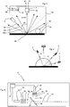
- FIG. 3 shows correspondingly an embodiment according to the invention of a device 1 for examining optical surface properties.
- a radiation device 2 which has an image recording unit 4a.
- This image recording unit 4a may be suitable for recording spatially resolved images B1, B2, which are each black and white images, or data sets that are characteristic of such images.
- the radiation device 2 directs radiation with a first wavelength range W1 and with a second wavelength range W2 on the surface. This irradiation takes place as mentioned above temporally offset.
- radiation with the wavelength range W3 can also be irradiated onto the surface.
- the reference symbol a1 denotes the angle of incidence under which the radiation from the radiation device 2 is irradiated onto the surface 10. This angle is indicated here in relation to a direction perpendicular to the surface.
- the angle b2 at which the radiation is received by the radiation detector device 4 is 0 °, i. the radiation is preferably absorbed under a direction perpendicular to the surface.
- the reference numeral 50 denotes a processor device which serves to evaluate the images taken by the image pickup unit 4a.
- the processor device 50 in this case has a comparison device 52 which compares the recorded images with one another. In this way, for example, the intensities recorded in the different color areas (from the black and white image camera) can be recorded. From this comparison of intensities, it is also possible to deduce the color impression of corresponding effect pigments.
- the reference numeral 54 denotes a memory device in which the individual images taken by the image recording device 4 or the individual values from which these images can be derived are stored. In this memory device position data can be stored, which are characteristic of a position of the device 1 relative to the surface.
- the device 1 may further comprise an output device for displaying the data, such as a display or the like.
- the various images or flakes are brought to coincide with the aid of suitable algorithms. This determines the pixels belonging to a flake from all images.
- the device according to the invention also has a position or distance detection device in order to be able to compare two recordings, which were recorded at different locations of the surface 10, also with regard to their spacing. In this way it is possible to measure a complete surface, for example the part of a body of a vehicle, by means of a large number of recordings. It is according to the invention that both the radiation device 2 and the radiation detector device 4 are arranged in a housing 60 and this housing substantially has an opening 62 in a region in which the radiation is to escape to the surface.
- a wheel 64 which serves to move the device 1 relative to the surface 10, can be arranged on the housing 60.
- This bike can also be beneficial serve to determine distances.
- the device 1 it would also be possible for the device 1 to be held on a moving element such as, for example, a robot arm and thus moved relative to the surface 10 to be examined.
- the images taken by the image recording device are also assigned positions of the device relative to the surface 10, or data which are characteristic of these positions. This assignment is advantageously carried out by means of a processor device.
- FIG. 4 shows a device according to a comparative example.
- a plurality of radiation devices 2 are provided, which radiate the light at different angles (in each case shown with respect to the vertical with respect to the surface 10). In this way, the surface is illuminated under the said different angles and the light is in each case received in a direction perpendicular to the surface 10 direction.
- Each of these radiation devices can be designed in the manner described above, that is, be suitable for the time-shifted output of radiations of different wavelengths.
- the device has at least two such radiation devices, which radiate the radiation at different angles onto the surface, and particularly preferably at least three radiation devices which radiate the radiation onto the surface 10 at different angles.
- the irradiation directions of a plurality of radiation devices and the beam direction of the radiation transmitted from the surface 10 to the image recording device 4 are in one plane. But it is also conceivable that radiation receiver and radiation device are not in one plane.
- FIG. 5 shows a representation of a radiation device 2.
- This radiation device here has a first radiation or light source 22 and a second radiation or light source 24.
- the first radiation source 22 emits a light beam S1 having a wavelength range W1, which strikes a mirror element 46, which may be a dichroic mirror here.
- the light beam S1 passes through this mirror element 46 due to its wavelength.
- the light source 24 also directs a second beam component S2 having a wavelength range W2 onto the mirror element 46.
- This mirror element 46 is designed such that it reflects the radiation S2 due to the other wavelength so that both the radiation S1 and the radiation S2 are collinear with one another Radiation device 2 escape.
- the two radiations S1 and S2 were shown offset to each other to illustrate the operation, but in fact the two radiations S1 and S2 would lie directly above each other.
- the reference numeral 32 refers to an optical element, such as a diffuser, on which the light coming from the light source 22 or 24 impinges.
- Reference numeral 34 denotes another optical element such as a lens device which serves to bundle the radiation S1 and S2, respectively.
- the reference numeral 36 may represent another optical element, such as a filter element, which will leak only a certain wavelength portion.
- Reference numeral 38 refers to an aperture device which also serves to form a clean light beam S1 and S2, respectively.
- the order of the elements 32, 34, 36, 38 in the direction of the light beams can also be designed differently depending on the application.
- a further light source 26 could also be provided which, for example, in FIG FIG. 5 to the right of the light source 24 and which also directs a beam S3 (not shown) vertically downwards onto another mirror element (not shown).
- a beam S3 (not shown) vertically downwards onto another mirror element (not shown).
- Optical elements 32, 34, 36, 38 could also be arranged after the mirror elements 46.
- FIG. 6 shows a further embodiment of a radiation device 2.
- three radiation sources 22, 24, 26 are provided, each of which direct their light onto a lens 32.
- the diffusing screen can be a holographic optical element.
- the light sources 22, 24, 26 are arranged such that they direct their light to a same area or the same point of the lens 32.
- reflective elements such as, for example, lenses, cylindrical lenses, apertured diaphragms and the like, may be arranged between the light sources and the diffusing screen 32.
- the reference numeral 30 both in FIG. 5 as well as in FIG. 6 refers to a control device which controls the radiation output by the radiation device 2.
- the radiation device can be controlled such that the individual light sources 22, 24, 26 emit their light with a time offset to one another. It may also be desired, depending on the measurement principle, that the light sources 22, 24, 26 at least temporarily emit light at the same time, so that a total of a mixture of light, for example a specific type of white light, can arise.
- the Fig. 7a, 7b show a further embodiment of a radiation device 2.
- the light sources 22, 24, 26, for example, as LED semiconductor chips on a support 40 and a substrate, such as ceramic are applied. These are then contacted (gebonded) to create the ability to individually control them. Since the semiconductor chips are sometimes significantly smaller than 0.5 mm 2 in dimension, they can be placed very close to each other. Thus, the deviation of the individual chips, which have a different spectral radiation characteristic, from the optical axis of the illumination system only very small and one can speak of a colinear illumination (S1, S2, S3). In the beam path also scattering discs 32, aperture 38, lenses 34, filters 36, holographic optical elements (not shown) can be introduced.
- Fig. 8 shows another possibility for the realization of the lighting.
- LEDs 22, 24, 26 arranged on a rotatable about a rotation axis D wheel.
- the wheel is turned further until the next LED lights up.
- the processor unit 50 can output information which is characteristic of the surface and in particular of its effect pigments. In particular, it is also possible to output information about the color properties of the effect pigments.
- the image data for each individual wavelength range can also be evaluated separately, for example with regard to a maximum intensity of the radiation impinging on the image recording unit. This evaluation also makes it possible to obtain color information as to whether a black-and-white image camera is used as the image recording device or a radiation detector device which itself outputs no color information.
- FIG. 5 and FIG. 6 it would be instead of in FIG. 5 and FIG. 6 also shown embodiments that only one light source 22 is present, which emits white light, for example, and between the light source 22 and the surface 10, a filter element is provided with variable filters, such as a filter wheel, or a tunable filter which can place different filter elements in the beam path , which each allow different color components of the light to reach the surface. Also by this device, the surface can be illuminated successively with changing colors.
- variable filters such as a filter wheel, or a tunable filter which can place different filter elements in the beam path , which each allow different color components of the light to reach the surface.
- the surface can be illuminated successively with changing colors.
- the device according to the invention and the method according to the invention can be used for quality assurance in connection with paints and in particular in the motor vehicle repair sector, in particular when using effect pigment paints.
- a suitable repair lacquer can be determined with the device according to the invention.
- the device according to the invention it would also be possible for the device according to the invention to output data which is used by a matching software in order to determine the data of a replacement paint.
- the recorded images can be evaluated in a variety of ways. It is pointed out in this context that the image analysis does not presuppose the black-and-white images recorded here, but is also applicable to color images.
- the radiation detector device can also be a color camera, a CCD chip or the like. So it would be possible, for example, the recorded images by diagrams, such as a histogram of the overall picture. In the context of the histogram, the rows or columns (of the recorded images) can be viewed individually and, for example, intensity values can be output per column or per row. It would also be possible for several rows or columns to be combined into groups in each case and corresponding mean values to be formed.
- the image may be binarized using, for example, a threshold method.
- the threshold value can in turn be characterized by different methods, such as a fixed value or a variable size (this variable size can be based on statistical parameters, for example).
- algorithms can also be used, such as an edge detection algorithm, which is used for the separation of pigments or flakes.
- a metrological or imagewise preparation separation of flakes on the one hand and defects, such as scratches, surface defects or dust on the other hand can be performed.
- defects such as scratches, surface defects or dust on the other hand
- a distinguishing feature it is possible, for example, for a distinguishing feature to be introduced, for example a distinguishing feature for a local extension.
- this distinguishing feature it is possible, for example, to distinguish (elongated) scratches from flakes on the one hand, but also to distinguish surface defects or the effects of dust among one another or flakes.
- a size and / or size distribution of the flake is determined by an evaluation of the image.
- a flake brightness distribution can also be determined, for example as a function of an illumination angle and / or the said threshold value.
- integral information of the individual black-and-white detectors or when using a color image of color detectors in the determination of effect characteristics.
- a correlating color value for example a color value correlating CIELab, can be determined for the flakes to be detected.
- a color camera and / or a suitable illumination such as in particular, but not exclusively RGB lighting, can be used.
- two dimensional arithmetic operations such as mathematical filters in only one dimension
- the calculation of the effect parameters can also be carried out by means of external (stand alone) computers, for example, or also, for example, via the Internet to a central computer.
- the individual effect parameters can be described by different criteria, such as the flake brightness, a flake size, a flake density, a local flake distribution and / or the like. Values determined in this way can also be compared with values stored in a database.
- HDR high-dynamic-range
- the individual surface parameters are performed by using various operators or calculations. These operators are advantageously selected from a group of operators or calculations which include Laplacian filters, Gabor filters, Momentum analyzes, Co-occurrence matrix, Haralick features. (Energy, entropy), LBP (local binary pattern) and / or autocorrelation function included.
- pattern recognition algorithms can also be carried out on the basis of several feature parameters.
- Fourier analyzes can also be carried out.
- Agreement between multiple instruments can be made by referencing samples, images and, for example, comparing them with stored images of a reference standard.
- HB-LEDs High Brithtness LEDs
- HB-LEDs High Brithtness LEDs
- dichroic filters can take place.
- colored "flakes” are dissolved or differentiated by the use of a plurality, in particular of at least two and in particular of three LEDs.
- red, green and blue LEDs are used.
- these three LEDs can be brought by means of dichroic filters or by the use of deflecting mirrors on a common optical axis and particularly preferably be switched sequentially. The detection of such images is done using a black and white camera.
- the measurement dynamics can also be increased by adapting and / or cascading an operating current of the illuminating LEDs, as has already been described by the applicant in the past.
- these mentioned measuring methods can be used in particular in the field of formulation, quality assurance and lookup, wherein particularly preferably an identification of a paint and / or a color by a Mehrwinkelfarbunk and a color image analysis takes place.
- at least two angles are measured, particularly preferably at least three angles.
- Goniometric measurements would also be possible, as in the DE 20 2004 011 8011 U1 described.
- a method for the optical examination of structured surfaces can be used, such as in DE 10 2009 033 110 A1 described.
- the surfaces and in particular of flakes which are selected in particular from a group of parameters which include the color, the planicity, the topographic structure, the integral reflectance, the angularly resolved Reflectance, sizes of flakes, distributions of flakes, scattering characteristics, combinations thereof or the like. It is also possible to characterize different varieties or groups of flakes, whereby both a characterization of a single type of flake and of a group of flak types is conceivable.
Landscapes
- General Health & Medical Sciences (AREA)
- Life Sciences & Earth Sciences (AREA)
- Chemical & Material Sciences (AREA)
- Analytical Chemistry (AREA)
- Biochemistry (AREA)
- Immunology (AREA)
- Physics & Mathematics (AREA)
- Health & Medical Sciences (AREA)
- Pathology (AREA)
- General Physics & Mathematics (AREA)
- Investigating Or Analysing Materials By Optical Means (AREA)
- Investigating Materials By The Use Of Optical Means Adapted For Particular Applications (AREA)
- Investigating Or Analyzing Non-Biological Materials By The Use Of Chemical Means (AREA)
- Length Measuring Devices By Optical Means (AREA)
Description
Die vorliegende Erfindung bezieht sich auf eine Vorrichtung und ein Verfahren zum Untersuchen von Oberflächen mit Effektbeschichtungen, welche sogenannte Effektpigmente aufweisen. Derartige Effektpigmente bewirken, dass die betreffende Schicht unter bestimmten Bedingungen, beispielsweise mit einem unter einem bestimmten Winkel einfallenden Licht glänzt bzw. glitzert oder eine bestimmte Farbe annimmt.The present invention relates to an apparatus and a method for examining surfaces with effect coatings which have so-called effect pigments. Such effect pigments cause the relevant layer to shine or glitter or assume a certain color under certain conditions, for example with a light incident at a certain angle.
Dabei sind aus dem Stand der Technik die unterschiedlichsten Effektpigmente bekannt und auch unterschiedlichste optische Eigenschaften derselben. So können beispielsweise diese Effektpigmente unterschiedlichste Farbumschläge aufweisen.In this case, the most varied effect pigments are known from the prior art and also very different optical properties of the same. For example, these effect pigments can have a wide variety of color changes.
Aus der
Die
Die
Aus der
Die
Aus dem Stand der Technik sind Messgeräte oder Vorrichtungen bekannt, die auch zur farblichen, bzw. optischen Erfassung derartiger Beschichtungen dienen. Diese Vorrichtungen weisen dabei üblicherweise mehrere Lichtquellen auf, welche bestimmtes Licht, beispielsweise normiertes Weißlicht unter unterschiedlichen Winkeln auf die jeweilige mit der Beschichtung versehene Oberfläche richten. Die von dieser Oberfläche zurückgeworfene Strahlung wird von einer Kamera, wie beispielsweise einer CCD-Farbkamera aufgenommen und die Bilder entsprechend ausgewertet.Measuring devices or devices are known from the prior art, which also serve for the color or optical detection of such coatings. In this case, these devices usually have a plurality of light sources which direct specific light, for example standardized white light, at different angles onto the respective surface provided with the coating. The radiation reflected by this surface is recorded by a camera, such as a CCD color camera, and the images are evaluated accordingly.
Dabei sind jedoch den Genauigkeiten derartiger Messungen systembedingt Grenzen gesetzt. Derartige Farbbildkameras weisen üblicherweise ein Array mit einer Vielzahl von Fotodetektoren auf, wobei zusätzlich noch diejenigen Detektoren, die zur Erfassung von roten Lichtkomponenten, die Detektoren, die zur Erfassung von grünen Lichtkomponenten und die Detektoren, die jeweils zur Erfassung von blauen Lichtkomponenten dienen, in jedenfalls noch gering unterschiedlichen Positionen angeordnet sind.However, the accuracies of such measurements are systemically limited. Such color image cameras usually have an array with a plurality of photodetectors, in addition to those detectors used to detect red light components, the detectors used to detect green light components and the Detectors, each serving to detect blue light components are arranged in any case still slightly different positions.
Falls nun derartige Beschichtungen mit Effektpigmenten von einem entsprechenden Gerät aufgenommen werden, ist es möglich, dass, wenn ein Effektpigment, beispielsweise Licht im rötlichen Farbbereich reflektiert, dieses Licht bei bestimmten Messungen auf diejenigen Fotozellen reflektiert wird, die zur Aufnahme von blauem oder grünem Licht gedacht sind. In diesem Falle werden die entsprechenden Fotozellen relativ geringe Werte oder Intensitäten anzeigen und auf diese Weise wird das Ergebnis verfälscht.If such coatings with effect pigments are taken up by a corresponding device, it is possible that when an effect pigment, for example, reflects light in the reddish color range, this light is reflected in certain measurements to those photocells which intended to receive blue or green light are. In this case, the corresponding photocells will display relatively low values or intensities, and thus the result will be falsified.
Ferner können bei der Beleuchtung mit mehreren Strahlungsquellen unterschiedlicher spektraler Zusammensetzung die einzelnen Beleuchtungsquelle individuell mit Strom versorgt werden. Dadurch kann man die Helligkeit dieser Beleuchtung optimal z.B. der Probe oder der Sensorcharakteristik anpassen und erreicht damit für jede Beleuchtung eine maximale Messdynamik.Furthermore, when lighting with multiple radiation sources of different spectral composition, the individual illumination source can be individually supplied with power. This makes it possible to optimize the brightness of this illumination, e.g. Adjust the sample or the sensor characteristic and thus achieves maximum measurement dynamics for each illumination.
Der vorliegenden Erfindung liegt daher die Aufgabe zugrunde, eine Vorrichtung und ein Verfahren zur Verfügung zu stellen, welches genauere bzw. weniger verfälschte Aufnahmen, insbesondere von Beschichtungen mit Effektpigmenten, ermöglicht. Diese Aufgabe wird durch die Gegenstände der unabhängigen Ansprüche erreicht. Vorteilhafte Ausführungsformen und Weiterbildungen sind Gegenstand der Unteransprüche.It is therefore an object of the present invention to provide a device and a method which enable more accurate or less distorted images, in particular of coatings with effect pigments. This object is achieved by the subject matters of the independent claims. Advantageous embodiments and further developments are the subject of the dependent claims.
Bei einem erfindungsgemäßen Verfahren zum Untersuchen von optischen Oberflächeneigenschaften von Oberflächen gemäß Anspruch 1 wird mit einer Strahlungseinrichtung unter einem vorgegebenen Einstrahlwinkel gegenüber der Oberfläche Strahlung auf die zu untersuchende Oberfläche eingestrahlt und die von dieser Oberfläche gestreute und/oder reflektierte Strahlung bzw. die allgemein von dieser Oberfläche weitergegebene Strahlung gelangt (zumindest teilweise) auf eine unter einem vorgegebenen Erfassungswinkel gegenüber der Oberfläche angeordnete Strahlungsdetektoreinrichtung mit einer schwarz/weiß-Bilder aufnehmenden Bildaufnahmeeinheit. Dabei erlaubt diese Strahlungsdetektoreinrichtung eine ortsaufgelöste Erfassung, der auf sie auftreffenden Strahlung.In a method according to the invention for examining optical surface properties of surfaces according to
Erfindungsgemäß richtet die Strahlungseinrichtung Strahlung mit einem ersten Wellenlängenbereich auf die Oberfläche und die Bildaufnahmeeinheit nimmt ein erstes ortsaufgelöstes Bild dieser von der Oberfläche gestreuten und/oder reflektierten, das heißt allgemein weitergegebenen Strahlen auf. Weiterhin richtet die Strahlungseinrichtung Strahlung mit einem zweiten Wellenlängenbereich auf die Oberfläche und die Bildaufnahmeeinheit nimmt ein zweites ortaufgelöstes Bild dieser von der Oberfläche gestreuten und/oder reflektierten Strahlung auf. Dabei unterscheiden sich die Strahlung mit dem ersten Wellenlängenbereich und die Strahlung mit dem zweiten Wellenlängenbereich wenigstens teilweise voneinander und diese Strahlungen gelangen zumindest teilweise zeitlich versetzt auf die Oberfläche. Dabei wird jedoch die Strahlung mit dem ersten Wellenlängenbereich sowie die Strahlung mit dem zweiten Wellenlängenbereich unter dem gleichen Einstrahlwinkel auf die Oberfläche eingestrahlt. Unter dem ortsaufgelösten Bild wird dabei nicht nur das eigentliche Bild verstanden, sondern auch eine Vielzahl von Daten (beispielsweise Intensitätswerten), aus denen sich dieses Bild zusammensetzt bzw. ableiten lässt.According to the invention, the radiation device directs radiation having a first wavelength range onto the surface, and the image acquisition unit records a first spatially resolved image of this beam, which is scattered and / or reflected by the surface, that is to say generally passed on. Furthermore, the radiation device directs radiation having a second wavelength range onto the surface and the image recording unit records a second spatially resolved image of this radiation scattered and / or reflected by the surface. In this case, the radiation with the first wavelength range and the radiation with the second wavelength range differ at least partially from one another, and these radiations reach the surface at least partially offset in time. In this case, however, the radiation with the first wavelength range and the radiation with the second wavelength range at the same angle of incidence are irradiated onto the surface. The spatially resolved image does not only mean the actual image, but also a multiplicity of data (for example intensity values) from which this image is composed or derived.
Es wird daher erfindungsgemäß vorgeschlagen, dass zur Aufnahme der Bilder zwar eine schwarz/weiß- oder eine Graustufenkamera (oder allgemein eine Kamera mit nur einer bestimmten Art von Pixeln) verwendet wird, welche eine höhere räumliche Auflösung , eine bessere Linearität, eine bessere Bauteil Reproduzierbarkeit , eine größere Messdynamik bei einem vergleichsweise niedrigen Bauteilpreis bietet. Um gleichwohl einen optischen Eindruck auch von der Farbe zu erreichen, wird vorgeschlagen, dass die Strahlungseinrichtung Licht mit unterschiedlicher Farbe auf die Oberfläche richtet und daher mehrere Bilder mit unterschiedlichen Farbkomponenten aufgenommen werden. Aus diesen jeweils aufgenommenen Bildern kann wiederum auch auf die farblichen Einflüsse der jeweiligen Oberfläche bzw. auch der Effektpigmente geschlossen werden.It is therefore proposed according to the invention that, although a black / white or grayscale camera (or generally a camera with only a certain type of pixels) is used to record the images, which has a higher spatial resolution, better linearity, better component reproducibility , offers a greater dynamic range at a comparatively low component price. Nevertheless, in order to achieve a visual impression of the color as well, it is proposed that the radiation device directs light of different color onto the surface and therefore several images with different color components are recorded. From these images taken in each case can also be concluded on the color influences of the respective surface or the effect pigments.
Erfindungsgemäß handelt es sich bei der von der Oberfläche gestreuten und/oder reflektierten Strahlung allgemein um diejenige Strahlung, welche als Folge der von der Strahlungseinrichtung eingestrahlten Strahlung weitergeleitet wird, insbesondere auf die Bildaufnahmeeinrichtung weitergeleitet wird.According to the invention, the radiation scattered and / or reflected by the surface is generally that radiation which, as a consequence of the radiation irradiated by the radiation device, is passed on, in particular to the image recording device.
Dabei ist es möglich, in dem Gesamtbild durch eine Schwellwertbildung die einzelnen Effektpigmente isoliert darzustellen und die charakteristischen optischen Eigenschaften dieser Effektpigmente wie z.B. Farbe, Reflexionsverhalten, räumliche Streucharakteristik zu bestimmen. Auch ist eine derartige isolierte Darstellung der Effektpigmente durch Schwellwertbildung in einem Histogramm möglich.In this case, it is possible to isolate the individual effect pigments in the overall image by thresholding and to determine the characteristic optical properties of these effect pigments, such as e.g. Color, reflection behavior, to determine spatial scattering characteristics. Such an isolated representation of the effect pigments is also possible by thresholding in a histogram.
Diese Schwellwertbestimmung kann sowohl örtlich als auch in einem Helligkeitshistogramm zur Anwendung kommen. Der Schwellwert kann dabei als ein fester oder als ein dynamischer Wert verwendet werden, der zum Beispiel in Abhängigkeit der Gesamthelligkeit des Bildes oder eines Bild Kontrastwertes ermittelt werden kann.This threshold determination can be applied both locally and in a brightness histogram. The threshold value can be used as a fixed value or as a dynamic value, which can be determined, for example, as a function of the overall brightness of the image or of an image contrast value.
Bei einem erfindungsgemäßen Verfahren erfolgt die mathematische Schwellenwertbildung dynamisch und die Schwellwertbildung wird von Bildinformationen wie Bildhelligkeit, Bildkontrast abgeleitet.In a method according to the invention, the mathematical thresholding takes place dynamically and the thresholding is derived from image information such as image brightness, image contrast.
Durch das Verrechnen der Flake Charakteristika der unterschiedlichen Bilder mit den Unterschiedlichen spektralen Beleuchtungen, können dadurch die optischen Eigenschaften der Effektpigmente unter dem jeweiligen Beleuchtungswinkel bestimmt werden. Was für die optische Charakterisierung der Effektflakes im Besonderen gilt ist auch für die Gesamtoberfläche anwendbar.By calculating the flake characteristics of the different images with the different spectral illuminations, the optical properties of the effect pigments can be determined under the respective illumination angle. What applies in particular to the optical characterization of effect flakes is also applicable to the overall surface.
Bei einem vorteilhaften Verfahren erfolgen die Bestrahlung der Oberfläche mit Strahlung mit dem ersten Wellenlängenbereich und die Bestrahlung mit Strahlung mit dem zweiten Wellenlängenbereich vollständig zeitlich voneinander versetzt.In an advantageous method, the irradiation of the surface with radiation takes place with the first wavelength range and the irradiation with radiation with the second wavelength range is completely offset in time from one another.
Bei einem weiteren vorteilhaften Verfahren sind auch die Wellenlängen der beiden Strahlungen, die auf die Oberfläche gerichtet werden, vollständig voneinander getrennt. Beispielsweise wird bei einem ersten Auftreffen grünes Licht verwendet und bei einem zweiten Auftreffen rotes Licht.In a further advantageous method, the wavelengths of the two radiations which are directed onto the surface are also completely separated from one another. For example, green light is used at a first impact and red light at a second impact.
Es wird daher bewusst das Bild mit einer schwarz/weiß-Kamera aufgenommen, da diese eine höhere Auflösung aufweist und keine Fehler durch unterschiedliche RGB-Detektoreinheiten der Kamera auftreten. Es wäre auch möglich, eine Farbkamera zu verwenden und die Werte der jeweiligen Sensorkomponenten zusammenzufassen.It is therefore deliberately taken the picture with a black and white camera, since this has a higher resolution and no errors occur through different RGB detector units of the camera. It would also be possible to use a color camera and summarize the values of the respective sensor components.
Erfindungsgemäß handelt es sich bei der Bildaufnahmeeinheit um eine Bildaufnahmeeinheit, welche eine Vielzahl von identischen Fotoelementen aufweist, das heißt insbesondere nur einen bestimmten Typ von Fotoelementen aufweist und daher nur zur Aufnahme von Schwarz/weiß- oder Graustufenbildern geeignet ist.According to the invention, the image acquisition unit is an image acquisition unit which has a multiplicity of identical photographic elements, that is to say in particular has only one specific type of photoelements and is therefore suitable only for taking black / white or gray scale images.
Vorzugsweise wird bei jeder Bildaufnahme pixelweise der individuelle Dunkelwert oder die Empfindlichkeit oder die Linearität, welche z.B. durch eine Vorab - Kalibrierung ermittelt wurden rechnerisch berücksichtigt. Damit werden Bauteiletoleranzen die auch zwischen einzelnen Pixeln auftreten können oder sonstige Artefakte kompensiert. Anders als bei der Verwendung einer Farbbildkamera müssen hier nicht die Unterschiede zwischen den einzelnen Farbpixeln berücksichtigt werden, bzw. Informationen nicht nach Farbpixeln separiert werden.Preferably, at each image acquisition, the individual dark value or sensitivity or linearity, which is e.g. calculated by a preliminary calibration were considered mathematically. This compensates for component tolerances that can occur between individual pixels or other artifacts. Unlike the use of a color camera, the differences between the individual color pixels need not be taken into account here, or information should not be separated into color pixels.
Bei einem erfindungsgemäßen Verfahren werden das erste von der Bildaufnahmeeinheit aufgenommene Bild und das zweite von der Bildaufnahmeeinheit aufgenommene Bild miteinander verglichen und oder miteinander verrechnet. Genauer gesagt werden vorteilhaft die für die jeweiligen Bilder charakteristischen (Intensitäts-)werte miteinander verglichen. Auf diese Weise können insbesondere die Farbanteile des auf die Bildaufnahmeeinheit auftreffenden Lichts ausgewertet werden. Vorteilhaft findet dabei dieser Vergleich ebenfalls ortsaufgelöst bzw. pixelweise statt. Damit ist es möglich, dass die einzelnen Signale der einzelnen Pixelelemente der Bildaufnahmeeinheit jeweils miteinander verglichen werden. Fasst man dabei mehrere Pixelelemente zusammen, die der Abbildung eines Effektpigmentes entsprechen, so erhält man dadurch die (bevorzugt gemittelten) pigmentspezifischen Eigenschaften. Bei einer Verrechnung der Bilder bzw. der charakteristischen Intensitätswerte können diese Werte beispielsweise miteinander multipliziert oder gemeinsam anderen mathematischen Operationen wie Mittelwertbildungen Summationen und dergleichen unterworfen werden.In a method according to the invention, the first image taken by the image recording unit and the second image taken by the image recording unit are compared and / or compared with one another. More specifically, advantageously, the (intensity) values characteristic of the respective images are compared with each other. In this way, in particular the color components of the light impinging on the image recording unit can be evaluated. Advantageously, this comparison also takes place spatially resolved or pixel-wise. This makes it possible for the individual signals of the individual pixel elements of the image acquisition unit to be compared with each other. If one summarizes several pixel elements which correspond to the image of an effect pigment, one thereby obtains the (preferably averaged) pigment-specific properties. By offsetting the images or the characteristic intensity values, these values can be multiplied together, for example, or subjected to other mathematical operations such as averaging summations and the like together.
Dabei ist es bevorzugt möglich, dass - insbesondere zum Zwecke dieses Vergleichs - Bilder oder Ausschnitte dieser Bilder mathematisch zur Deckung gebracht werden. Es kann dabei sowohl ein (insbesondere pixelweiser) Vergleich der gesamten Bilder stattfinden oder aber der Vergleich bezieht sich erfindungsgemäß auf einzelne Pixelbezirke des Bildes. In diesem Fall werden bevorzugt solche Pixelbezirke bzw. Pixelbereiche für den Vergleich ausgewählt, welche weitgehend der Abbildung der Effektpigmente entsprechen. Zur Ermittlung dieser Bezirke kann die oben beschriebene Schwellwertbildung zur Anwendung kommen Aus diesem Vergleich kann auf die farblichen Eigenschaften der Oberfläche bzw. der einzelnen Effektpigmente (Sparkles) geschlossen werden.It is preferably possible that - especially for the purpose of this comparison - images or sections of these images are mathematically brought to coincidence. It can do that both a (in particular pixelwise) comparison of the entire images take place or else the comparison relates to individual pixel areas of the image according to the invention. In this case, those pixel areas or pixel areas are preferably selected for the comparison, which largely correspond to the image of the effect pigments. To determine these districts, the threshold value formation described above can be used. From this comparison, it is possible to deduce the color properties of the surface or the individual effect pigments (sparkles).
Denkbar wäre auch eine Kameratechnologie, die derartig konstruiert ist, dass jedes Pixel nicht nur die Helligkeit sondern auch eine spektrale Information des auf es auftreffenden Lichts aufzeichnet. Bei derartigen Kameras werden gleichwohl, anders als bei Farbbildkameras, einheitliche Pixel verwendet.Also conceivable would be a camera technology that is constructed in such a way that each pixel records not only the brightness but also spectral information of the light striking it. However, unlike color cameras, uniform pixels are used in such cameras.
Bei einem erfindungsgemäßen Verfahren ist die Oberfläche eine mit einer Lackschicht versehene Oberfläche. Damit kann es sich beispielsweise und bevorzugt um die Oberflächen von Fahrzeugkarosserien handeln, es wäre jedoch auch möglich, dass es sich bei den Oberflächen um Oberflächen von Möbelstücken, beispielsweise von Tischen oder dergleichen, handelt.In a method according to the invention, the surface is a surface provided with a lacquer layer. This may, for example and preferably, be the surfaces of vehicle bodies, but it would also be possible for the surfaces to be surfaces of pieces of furniture, for example tables or the like.
Bei einem erfindungsgemäßen Verfahren weist die Lackschicht Effektpigmente auf. Bei diesen Effektpigmenten kann es sich, wie oben erwähnt, beispielsweise um kleine Metallteilchen handeln, welche in der Schicht vorhanden sind. Vorteilhaft weisen dabei diese Effektpigmente ein Flopverhalten auf, das heißt beispielsweise einen bestimmten Farbumschlag oder auch Intensitätsumschlag, je nachdem unter welchem Winkel das Licht auf die Pigmente auftrifft.In a method according to the invention, the lacquer layer has effect pigments. As mentioned above, these effect pigments may, for example, be small metal particles present in the layer. Advantageously, these effect pigments have a flop behavior, that is, for example, a certain color change or intensity change, depending on the angle at which the light impinges on the pigments.
Bei einem weiteren vorteilhaften Verfahren ist die Strahlungseinrichtung derart gestaltet, dass die Strahlungen unter den beiden unterschiedlichen Wellenlängen unter genau dem gleichen Winkel auf die Oberfläche einstrahlen. Damit werden vorteilhaft die Strahlungen mit dem ersten Wellenlängenbereich und die Strahlungen mit dem zweiten Wellenlängenbereich kollinear zueinander auf die Oberfläche eingestrahlt.In a further advantageous method, the radiation device is designed in such a way that the radiations under the two different wavelengths radiate onto the surface at exactly the same angle. In this way, advantageously, the radiations with the first wavelength range and the radiations with the second wavelength range are collinear with one another on the surface.
Bei einem weiteren vorteilhaften Verfahren wird unter dem ersten Einstrahlwinkel zusätzlich noch Strahlung mit einem dritten Wellenlängenbereich, der sich vom ersten Wellenlängenbereich und auch vom zweiten Wellenlängenbereich unterscheidet, auf die Oberfläche eingestrahlt und die Bildaufnahmeeinheit nimmt die von der Oberfläche reflektierte und/oder gestreute Strahlung auf, und nimmt auf diese Weise weiterhin ein drittes ortsaufgelöstes Bild auf.In a further advantageous method, radiation having a third wavelength range, which differs from the first wavelength range and also from the second wavelength range, is additionally irradiated onto the surface at the first angle of incidence and the imaging unit absorbs the radiation reflected and / or scattered by the surface, and thus continues to take a third spatially resolved image.
Vorteilhaft erfolgt auf die Aufnahme dieses dritten Bildes zeitlich versetzt zu den beiden anderen Bildern. So ist es beispielsweise möglich, dass Licht unter drei unterschiedlichen Farben, beispielsweise rot, grün und blau auf die Oberfläche eingestrahlt wird. Aus dem Vergleich der Bilder können auf diese Weise auch die Farben der einzelnen Pigmente ermittelt werden, bzw. die Farben, unter denen die Pigmente Licht zurückreflektieren. Falls beispielsweise ein bestimmtes Pixel der Bildaufnahmeeinheit an einer bestimmten Stelle einen hohen Intensitätswert im roten Bereich zeigt, kann man hieraus schließen, dass das entsprechende Sparkle bzw. Effektpigment das Licht insbesondere mit roten Wellenlängenbereich zurückreflektiert.Advantageously takes place on the recording of this third image with a time offset to the other two images. It is thus possible, for example, for light to be irradiated onto the surface under three different colors, for example red, green and blue. By comparing the images, the colors of the individual pigments can be determined in this way, or the colors under which the pigments reflect light back. If, for example, a particular pixel of the image acquisition unit shows a high intensity value in the red region at a certain point, it can be concluded from this that the corresponding sparkle or effect pigment reflects back the light, in particular with a red wavelength range.
So kann näherungsweise zum Beispiel der Farbwert der im Lack enthaltenen Effektpigmente in der Maßeinhalt für Farbe, z.B. dem CIELab System dargestellt werden.Thus, for example, the color value of the effect pigments contained in the paint can be approximated in the dimensional content for color, e.g. the CIELab system.
Auch hier werden die beiden Bilder mit Strahlung unter dem gleichen Einfallswinkel aufgenommen.Again, the two images are recorded with radiation at the same angle of incidence.
Vorteilhaft handelt es sich bei der Strahlung um Licht und besonders bevorzugt um Licht im sichtbaren Wellenlängenbereich.Advantageously, the radiation is light and more preferably light in the visible wavelength range.
Die vorliegende Erfindung ist weiterhin auf eine Vorrichtung zum Untersuchen von optischen Oberflächeneigenschaften gemäß Anspruch 4 gerichtet. Diese Vorrichtung weist eine erste Strahlungseinrichtung auf, welche Strahlung unter einem vorgegebenen Einstrahlwinkel auf eine zu untersuchende Oberfläche richtet. Weiterhin weist die Vorrichtung eine Strahlungsdetektoreinrichtung auf, welche die auf die Oberfläche von der ersten Strahlungseinrichtung eingestrahlte und von der Oberfläche unter einen Erfassungswinkel zurückgeworfene bzw. weitergegebene Strahlung aufnimmt. Dabei weist die Strahlungsdetektoreinrichtung eine ortsaufgelöste schwarz/weiß-Bilder aufnehmende Bildaufnahmeeinheit auf.The present invention is further directed to an apparatus for inspecting optical surface properties according to
Erfindungsgemäß ist die Strahlungseinrichtung derart ausgestaltet, dass sie zur wenigstens teilweise zeitlich versetzten Ausgabe von Strahlung in wenigstens zwei unterschiedlichen Wellenlängenbereichen unter dem gleichen Einstrahlwinkel geeignet ist und die Bildaufnahmeeinheit bis zur Aufnahme von einem ersten Bild, welches zu der Strahlung mit dem ersten Wellenlängenbereich korrespondiert, welches zu der Strahlung mit dem ersten Wellenlängenbereich korrespondiert und zur Aufnahme von einem zweiten Bild geeignet ist.According to the invention, the radiation device is designed in such a way that it is suitable for outputting radiation in at least two different wavelength ranges under the same angle of incidence at least partially with respect to time, and the image acquisition unit until the acquisition of a first image which corresponds to the radiation with the first wavelength range corresponds to the radiation having the first wavelength range and is suitable for receiving a second image.
Damit wird auch hier vorgeschlagen, dass die Bildaufnahmeeinheit Bilder von Strahlungen mit zwei unterschiedlichen Wellenlängen aufnimmt und diese unterschiedlichen Wellenlängen jeweils unter dem gleichen Einstrahlwinkel auf die Oberfläche eingestrahlt werden. Unter der korrespondierenden Strahlung wird dabei diejenige Strahlung verstanden, welche von der entsprechenden Strahlungseinrichtung mit dem besagten ersten bzw. zweiten Wellenlängenbereich auf die Oberfläche eingestrahlt wurde.Thus, it is also proposed here that the image recording unit records images of radiations with two different wavelengths and these different wavelengths are irradiated in each case at the same angle of incidence on the surface. In this case, the corresponding radiation is understood to mean that radiation which has been radiated onto the surface by the corresponding radiation device with the said first or second wavelength range.
Vorteilhaft ist die Strahlungseinrichtung auch zur Ausgabe von Strahlungen mit einem dritten Wellenlängenbereich geeignet und vorteilhaft die Bildaufnahmeeinheit auch zur Aufnahme eines dritten ortsaufgeösten Bildes (somit dem besagten Wellenlängenbereich).Advantageously, the radiation device is also suitable for emitting radiation with a third wavelength range and, advantageously, the image recording unit also for recording a third spatially resolved image (thus the said wavelength range).
Die Vorrichtung weist eine Vergleichseinrichtung auf, welche wenigstens das erste Bild mit dem zweiten Bild vergleicht. Mit diesem Vergleich kann dabei insbesondere auch auf farbliche Charakteristika der Oberfläche bzw. der Effektpigmente geschlossen werden.The device has a comparison device which compares at least the first image with the second image. In particular, color characteristics of the surface or of the effect pigments can be concluded with this comparison.
Vorteilhaft weist die Vorrichtung eine Vielzahl von Strahlungseinrichtungen auf, welche die Oberfläche unter unterschiedlichen Winkeln beleuchten. Dabei sind vorteilhaft mehrere Strahlungseinrichtungen und besonders bevorzugt alle der Strahlungseinrichtungen zur Abgabe von Licht in unterschiedlichen Wellenlängenbereichen geeignet. Damit strahlen diese Strahlungseinrichtungen das Licht unter unterschiedlichen Winkeln auf die Oberfläche ein.Advantageously, the device has a plurality of radiation devices which illuminate the surface at different angles. Advantageously, a plurality of radiation devices and particularly preferably all of the radiation devices are suitable for emitting light in different wavelength ranges. Thus, these radiation devices irradiate the light at different angles to the surface.
Erfindungsgemäß weist die Strahlungseinrichtung eine erste Lichtquelle auf, welche Strahlung in dem ersten Wellenlängenbereich abgibt sowie eine zweite Lichtwelle, welche Strahlung in dem zweiten Wellenlängenbereich abgibt sowie eine Strahlungsleitanordnung, welche bewirkt, dass die Strahlung in dem ersten Wellenlängenbereich und die Strahlung in dem zweiten Wellenlängenbereich unter dem gleichen Einstrahlwinkel auf die Oberfläche eingestrahlt werden. Dabei handelt es sich bei der ersten Lichtquelle und auch bei der zweiten Lichtwelle jeweils um Leuchtdioden Diese Leuchtdioden können dabei Licht in unterschiedlichen Wellenlängenbereichen auf die Oberfläche richten.According to the invention, the radiation device has a first light source, which emits radiation in the first wavelength range, and a second light wave, which emits radiation in the second wavelength range, and a radiation guide, which effects the radiation in the first wavelength range and the radiation in the second wavelength range be irradiated to the surface at the same angle of incidence. These are in the first light source and also in the second light wave in each case to light-emitting diodes These light-emitting diodes can direct light in different wavelength ranges on the surface.
Die Strahlungsleitanordnung bewirkt, dass die Strahlung der ersten Lichtquelle und der zweiten Lichtquelle im Wesentlichen kollinear auf die Oberfläche auftreffen. Anstelle der Strahlungsleitanordnung wäre es auch möglich, dass nur eine Lichtquelle vorgesehen ist und dafür mehrere Filterelemente, welche vor diese Lichtquelle geschoben werden können. Auch auf diese Weise wäre es möglich, Licht mit unterschiedlichen Wellenlängen kollinear auf dieThe radiation guide arrangement causes the radiation of the first light source and the second light source to strike the surface substantially collinearly. Instead of Strahlungsleitanordnung it would also be possible that only one light source is provided and for several filter elements which can be pushed in front of this light source. Also in this way it would be possible to collinear light with different wavelengths on the
Oberfläche zu werfen, wobei in diesem Falle jedoch die Intensität der auf die Oberfläche treffenden Strahlung jeweils durch die Filterelemente abgeschwächt wird.To throw surface, in which case, however, the intensity of the incident on the surface radiation is attenuated respectively by the filter elements.
Bei einer weiteren vorteilhaften Ausführungsform weist die Strahlungsleitanordnung wenigstens ein Spiegelelement auf. Mit diesem Spiegelelement kann es sich beispielsweise um einen dichroitischen Spiegel handeln, der Licht einer bestimmten Wellenlänge passieren lässt und Licht einer weiteren Wellenlänge mehr oder weniger vollständig reflektiert (oder absorbiert). Neben oder zusätzlich zu den Spiegelelementen können jedoch auch andere Elemente, beispielsweise Streuscheiben, Linsen und dergleichen Anwendung finden.In a further advantageous embodiment, the radiation guide arrangement has at least one mirror element. By way of example, this mirror element can be a dichroic mirror which allows light of a certain wavelength to pass through and more or less completely reflects (or absorbs) light of a further wavelength. In addition to or in addition to the mirror elements, however, other elements, such as lenses, lenses and the like may find application.
Bei einer weiteren vorteilhaften Ausführungsform weist die Vorrichtung wenigstens eine Prozessoreinrichtung auf, welche aus einem Vergleich der aufgenommenen Bilder eine Information ermittelt, welche für eine Farbe wenigstens eines Abschnitts der Oberfläche charakteristisch ist. Bevorzugt wird eine Eigenschaft ermittelt, die für die Sparkles oder ein optisches Verhalten wenigstens eines Effektpigments und bevorzug einer Vielzahl von Effektpigmenten charakteristisch ist. Vorteilhaft wertet damit die Prozessoreinrichtung die jeweiligen Bilder ortsaufgelöst auf und führt daher auch einen Vergleich jeweils ortsaufgelöst bzw. einzeln für die jeweiligen Pixel der Bildaufnahmeeinheit durch.In a further advantageous embodiment, the device has at least one processor device which, from a comparison of the recorded images, determines information which is characteristic of a color of at least one section of the surface. Preferably, a property is determined which is characteristic of the sparkles or an optical behavior of at least one effect pigment and preferably a multiplicity of effect pigments. Advantageously, the processor device thus evaluates the respective images spatially resolved and therefore also carries out a comparison in each case in a spatially resolved or individual manner for the respective pixels of the image recording unit.
Weitere vorteilhafte Ausführungsformen und vergleichende Beispiele ergeben sich aus den beigefügten Zeichnungen:
Darin zeigen:
- Fig. 1a -1c
- drei Darstellungen zur Veranschaulichung von Effektpigmenten;
- Fig. 2
- eine Darstellung einer Bildaufnahmeeinheit für eine Farbbildkamera;
- Fig. 3
- eine schematische Darstellung einer erfindungsgemäßen Vorrichtung;
- Fig. 4
- eine schematische Darstellung einer Vorrichtung gemäß eines vergleichenden Beispiels;
- Fig. 5
- eine Darstellung einer ersten Ausführungsform einer Strahlungseinrichtung;
- Fig. 6
- eine weitere Ausführungsform einer erfindungsgemäßen Strahlungseinrichtung;
- Fig. 7a,b
- eine weitere Ausführungsform einer erfindungsgemäßen Strahlungseinrichtung; und
- Fig. 8
- eine weitere Ausführungsform einer erfindungsgemäßen Strahlungseinrichtung.
Show:
- Fig. 1a -1c
- three illustrations to illustrate effect pigments;
- Fig. 2
- a representation of an image pickup unit for a color camera;
- Fig. 3
- a schematic representation of a device according to the invention;
- Fig. 4
- a schematic representation of an apparatus according to a comparative example;
- Fig. 5
- a representation of a first embodiment of a radiation device;
- Fig. 6
- a further embodiment of a radiation device according to the invention;
- Fig. 7a, b
- a further embodiment of a radiation device according to the invention; and
- Fig. 8
- a further embodiment of a radiation device according to the invention.
Die
Bei der in
Die im Beispiel von
Bei diesen Farbflops kann es sich sowohl um einen Hell/dunkel-Flop als auch um einen Farbflop handeln. Damit ist der Farbeindruck auch abhängig von der Beleuchtungs- und Beobachtunggeometrie.These color flops can be both a light / dark flop and a color flop. Thus, the color impression is also dependent on the lighting and observation geometry.
Zur Anwendung kommen auch farbig eingefärbte Substrate wir z.B. Glasflakes oder Flakes auf SlO2 Basis, welche das Licht gefiltert in eine bestimmte Richtung spiegeln.We also use colored substrates such as glass flakes or flakes based on SIO 2 , which reflect the light filtered in a specific direction.
Durch eine geeignete spektrale Wahl des beleuchtenden Lichtes ist es auch möglich nicht sichtbare Phänomene, wie z.B. die Wärmerückstrahlung der Pigmente zu charakterisieren.By means of a suitable spectral selection of the illuminating light, it is also possible to characterize non-visible phenomena, such as, for example, the heat radiation of the pigments.
Die Strahlungseinrichtung 2 richtet dabei Strahlungen mit einem ersten Wellenlängenbereich W1 und mit einem zweiten Wellenlängenbereich W2 auf die Oberfläche. Dieses Einstrahlen erfolgt dabei wie oben erwähnt zeitlich versetzt. Daneben kann auch noch Strahlung mit dem Wellenlängenbereich W3 auf die Oberfläche eingestrahlt werden. So wäre es möglich, dass nacheinander zunächst grünes, dann rotes, dann blaues Licht auf die Oberfläche eingestrahlt wird und die jeweiligen Reaktionen von der Bildaufnahmeeinheit jeweils als Bilder B1, B2, B3 ausgegeben werden.The
Das Bezugszeichen a1 kennzeichnet den Einstrahlwinkel unter dem die Strahlung von der Strahlungseinrichtung 2 auf die Oberfläche 10 eingestrahlt wird. Dieser Winkel ist hier gegenüber einer zu der Oberfläche senkrechten Richtung angegeben. Entsprechend beträgt der Winkel b2, unter dem die Strahlung von der Strahlungsdetektoreinrichtung 4 aufgenommen wird, 0°, d.h. die Strahlung wird vorzugsweise unter einer gegenüber der Oberfläche senkrecht stehenden Richtung aufgenommen.The reference symbol a1 denotes the angle of incidence under which the radiation from the
Das Bezugszeichen 50 kennzeichnet eine Prozessoreinrichtung, die zur Auswertung der von der Bildaufnahmeeinheit 4a aufgenommenen Bilder dient. Die Prozessoreinrichtung 50 weist dabei eine Vergleichseinrichtung 52 auf, welche die aufgenommenen Bilder miteinander vergleicht. Auf diese Weise können beispielsweise die Intensitäten festgehalten werden, die in den unterschiedlichen farblichen Bereichen (von der schwarz/weiß-Bildkamera) aufgenommen wurden. Aus diesem Intensitätenvergleich kann auch auf den farblichen Eindruck entsprechender Effektpigmente geschlossen werden.The
Das Bezugszeichen 54 kennzeichnet eine Speichereinrichtung, in der die einzelnen von der Bildaufnahmeeinrichtung 4 aufgenommenen Bilder bzw. die einzelnen Werte, aus denen diese Bilder ableitbar sind, abgespeichert werden. In dieser Speichereinrichtung können Positionsdaten abgespeichert werden, die für eine Position der Vorrichtung 1 gegenüber der Oberfläche charakteristisch sind. Die Vorrichtung 1 kann weiterhin eine Ausgabeeinrichtung aufweisen, um die Daten darzustellen wie etwa ein Display oder dergleichen.The
In einer Recheneinrichtung werden mit Hilfe geeigneter Algorithmen die verschiedenen Bilder, bzw. Flakes zur Deckung gebracht. Dadurch werden die zu einem Flake gehörenden Pixel aus allen Bildern bestimmt.In a computing device, the various images or flakes are brought to coincide with the aid of suitable algorithms. This determines the pixels belonging to a flake from all images.
Vorteilhaft weist die erfindungsgemäße Vorrichtung auch eine Positions- bzw. Entfernungserfassungseinrichtung auf, um zwei Aufnahmen, die an unterschiedlichen Orten der Oberfläche 10 aufgenommen wurden, miteinander auch hinsichtlich ihres Abstandes vergleichen zu können. Auf diese Weise ist es möglich, durch eine Vielzahl von Aufnahmen eine komplette Oberfläche, beispielsweise den Teil einer Karosserie eines Fahrzeugs zu vermessen. Es ist erfindungsgemäß, dass sowohl die Strahlungseinrichtung 2 als auch die Strahlungsdetektoreinrichtung 4 in einem Gehäuse 60 angeordnet ist und dieses Gehäuse im Wesentlichen eine Öffnung 62 in einem Bereich aufweist, in dem die Strahlung auf die Oberfläche austreten soll.Advantageously, the device according to the invention also has a position or distance detection device in order to be able to compare two recordings, which were recorded at different locations of the
Weiterhin kann an dem Gehäuse 60 ein Rad 64 angeordnet sein, welches zum Bewegen der Vorrichtung 1 gegenüber der Oberfläche 10 dient. Vorteilhaft kann dieses Rad dabei auch zur Bestimmung von Entfernungen dienen. Es wäre jedoch auch möglich, dass die Vorrichtung 1 an einem Bewegungselement wie beispielsweise an einem Roboterarm gehalten wird und so gegenüber der zu untersuchenden Oberfläche 10 bewegt wird.Furthermore, a
Vorteilhaft werden den von der Bildaufnahmeeinrichtung aufgenommenen Bildern auch Positionen der Vorrichtung gegenüber der Oberfläche 10 zugeordnet, bzw. Daten, welche für diese Positionen charakteristisch sind. Diese Zuordnung erfolgt vorteilhaft mittels einer Prozessoreinrichtung.Advantageously, the images taken by the image recording device are also assigned positions of the device relative to the
Vorteilhaft weist die Vorrichtung wenigstens zwei derartige Strahlungseinrichtungen auf, welche die Strahlung unter unterschiedlichen Winkeln auf die Oberfläche einstrahlen und besonders bevorzugt wenigstens drei Strahlungseinrichtungen, welche die Strahlung unter unterschiedlichen Winkeln auf die Oberfläche 10 einstrahlen. Vorteilhaft liegen die Einstrahlrichtungen mehrerer Strahlungseinrichtungen und die Strahlrichtung der von der Oberfläche 10 auf die Bildaufnahmeeinrichtung 4 weitergeleiteten Strahlung in einer Ebene. Es ist aber auch denkbar, dass Strahlungsempfänger und Strahlungseinrichtung nicht in einer Ebene liegen.Advantageously, the device has at least two such radiation devices, which radiate the radiation at different angles onto the surface, and particularly preferably at least three radiation devices which radiate the radiation onto the
Die Lichtquelle 24 richtet eine zweite Strahlenkomponente S2 mit einem Wellenlängenbereich W2 ebenfalls auf das Spiegelelement 46. Dieses Spiegelelement 46 ist dabei derart gestaltet, dass er die Strahlung S2 aufgrund der anderen Wellenlänge reflektiert, sodass sowohl die Strahlung S1 als auch die Strahlung S2 kollinear zueinander aus Strahlungseinrichtung 2 austreten. In
Das Bezugszeichen 32 bezieht sich auf ein optisches Element wie beispielsweise eine Streuscheibe, auf welche das von der Lichtquelle 22 bzw. 24 kommende Licht auftrifft. Das Bezugszeichen 34 kennzeichnet ein weiteres optisches Element wie beispielsweise eine Linseneinrichtung, die zum Bündeln der Strahlung S1 bzw. S2 dient. Das Bezugszeichen 36 kann ein weiteres optisches Element wie beispielsweise ein Filterelement darstellen, das nur einen bestimmten Wellenlängenanteil austreten lässt. Das Bezugszeichen 38 bezieht sich jeweils auf eine Blendeneinrichtung, die ebenfalls zum Bilden eines sauberen Lichtstrahls S1 bzw. S2 dient. Die Reihenfolge der Elemente 32, 34, 36, 38 in Richtung der Lichtstrahlen kann je nach Anwendung auch anders gestaltet sein.The
Zusätzlich zu den beiden Lichtquellen 22 und 24 könnte auch noch eine weitere Lichtquelle 26 vorgesehen sein, welche beispielsweise in
Entlang der Strahlenpfade S1, S2, S3 können auch weitere optische Elemente wie Linsen 34 oder Lochblenden 38 oder dergleichen vorgesehen sein.Along the beam paths S1, S2, S3, other optical elements such as
Das Bezugszeichen 30 sowohl in
Die
Bei einem Ablauf des erfindungsgemäßen Verfahrens wird also zunächst Licht in einer ersten Wellenlänge W1 auf die Oberfläche und von der Oberfläche auf die Bildaufnahmeeinheit 4a gerichtet. Danach wird Licht mit dem Wellenlängenbereich W2 eingestrahlt und entsprechend aufgenommen. Anschließend werden von der Bildaufnahmeeinheit die entsprechenden Bilder B1 und B2 (bzw. die entsprechenden Werte) an eine Prozessoreinheit übergeben und von dieser miteinander verglichen. Auf Basis dieses Vergleichs kann die Prozessoreinheit 50 Informationen ausgeben, welche für die Oberfläche und insbesondere auch deren Effektpigmente charakteristisch sind. Insbesondere können dabei auch Informationen über farbliche Eigenschaften der Effektpigmente ausgegeben werden. Es können jedoch auch die Bilddaten zu jedem einzelnen Wellenlängenbereich getrennt ausgewertet werden, beispielsweise hinsichtlich einer maximalen Intensität der auf die Bildaufnahmeeinheit auftreffenden Strahlung. Auch durch diese Auswertung ist es möglich, farbliche Informationen zu gewinnen, ob wohl als Bildaufnahmeeinrichtung eine Schwarz-Weiß - Bildkamera verwendet wird bzw. eine Strahlungsdetektoreinrichtung, die selbst keine Farbinformationen ausgibt.In a sequence of the method according to the invention, therefore, first of all light is directed onto the surface in a first wavelength W1 and onto the
In nicht-erfindungsgemäßen, vergleichenden Beispielen wäre es anstelle der in
Die erfindungsgemäße Vorrichtung sowie das erfindungsgemäße Verfahren können zur Qualitätssicherung in Verbindung mit Lacken und insbesondere im KFZ - Reparaturbereich eingesetzt werden, insbesondere bei der Verwendung von Effektpigmentlacken. Im Einzelnen kann mit der erfindungsgemäßen Vorrichtung ein geeigneter Reparaturlack ermittelt werden. Daneben wäre es auch möglich, dass die erfindungsgemäße Vorrichtung Daten ausgibt, welche von einer Matching - Software genutzt wird, um die Daten eines Ersatzlacks zu bestimmen.The device according to the invention and the method according to the invention can be used for quality assurance in connection with paints and in particular in the motor vehicle repair sector, in particular when using effect pigment paints. In detail, a suitable repair lacquer can be determined with the device according to the invention. In addition, it would also be possible for the device according to the invention to output data which is used by a matching software in order to determine the data of a replacement paint.
Die aufgenommenen Bilder können in unterschiedlichster Weise ausgewertet werden. Es wird in diesem Zusammenhang darauf hingewiesen, dass die Bildauswertung nicht die hier beschriebenen schwarz-weiß aufgenommenen Bilder voraussetzt, sondern auch entsprechend auf Farbbilder anwendbar ist. Damit kann es sich hier bei der Strahlungsdetektoreinrichtung auch um eine Farbbildkamera, einen CCD-Chip oder dergleichen handeln. So wäre es beispielsweise möglich, die aufgenommenen Bilder durch Diagramme, wie ein Histogramm des Gesamtbildes zu charakterisieren. Dabei können im Rahmen des Histogramms die Zeilen oder Spalten (der aufgenommenen Bilder) jeweils einzeln betrachtet werden und beispielsweise pro Spalte oder pro Zeile Intensitätswerte ausgegeben werden. Auch wäre es möglich, dass mehrere Zeilen bzw. Spalten jeweils zu Gruppen zusammengefasst werden und entsprechende Mittelwerte gebildet werden.The recorded images can be evaluated in a variety of ways. It is pointed out in this context that the image analysis does not presuppose the black-and-white images recorded here, but is also applicable to color images. Thus, the radiation detector device can also be a color camera, a CCD chip or the like. So it would be possible, for example, the recorded images by diagrams, such as a histogram of the overall picture. In the context of the histogram, the rows or columns (of the recorded images) can be viewed individually and, for example, intensity values can be output per column or per row. It would also be possible for several rows or columns to be combined into groups in each case and corresponding mean values to be formed.
Bei einem weiteren anwendbaren Verfahren kann das Bild binärisiert werden, beispielsweise unter Verwendung eines Schwellwertverfahrens. Der Schwellwert kann dabei wiederum über unterschiedliche Verfahren charakterisiert werden, wie zum Beispiel über einen fest definierten Wert oder auch eine variable Größe (diese variable Größe kann beispielsweise auf statistischen Kenngrößen basieren).In another applicable method, the image may be binarized using, for example, a threshold method. The threshold value can in turn be characterized by different methods, such as a fixed value or a variable size (this variable size can be based on statistical parameters, for example).
Daneben können auch Algorithmen eingesetzt werden, wie etwa ein Kanten-Detektionsalgorithmus, der zur Separation von Pigmenten oder Flakes verwendet wird.In addition, algorithms can also be used, such as an edge detection algorithm, which is used for the separation of pigments or flakes.
Bei weiteren optischen Verfahren kann eine messtechnische bzw. bildaufbereitungsmäßige Trennung von Flakes einerseits und Defekten, wie Kratzern, Oberflächendefekten oder auch Staub andererseits durchgeführt werden. Dabei ist es möglich, dass beispielsweise ein Unterscheidungsmerkmal eingeführt wird, etwa ein Unterscheidungsmerkmal für eine örtliche Ausdehnung. Anhand dieses Unterscheidungsmerkmals ist es möglich, beispielsweise (langestreckte) Kratzer einerseits von Flakes zu unterscheiden, aber auch Oberflächendefekte oder die Einflüsse von Staub untereinander oder von Flakes zu unterscheiden.In other optical methods, a metrological or imagewise preparation separation of flakes on the one hand and defects, such as scratches, surface defects or dust on the other hand can be performed. It is possible, for example, for a distinguishing feature to be introduced, for example a distinguishing feature for a local extension. On the basis of this distinguishing feature it is possible, for example, to distinguish (elongated) scratches from flakes on the one hand, but also to distinguish surface defects or the effects of dust among one another or flakes.
Bei einem weiteren vorteilhaften Verfahren wird durch eine Auswertung des Bildes eine Größe und/oder Größenverteilung des Flakes ermittelt. Daneben oder zusätzlich kann auch eine Flakes-Helligkeitsverteilung ermittelt werden, beispielsweise in Abhängigkeit von einem Beleuchtungswinkel und/oder dem besagten Schwellwert. Daneben ist es auch möglich, bei der Ermittlung von Effektkenngrößen integrale Informationen der einzelnen Schwarz-Weiß-Detektoren oder bei Verwendung eines Farbbildes von Farbdetektoren einzusetzen.In a further advantageous method, a size and / or size distribution of the flake is determined by an evaluation of the image. In addition or in addition, a flake brightness distribution can also be determined, for example as a function of an illumination angle and / or the said threshold value. In addition, it is also possible to use integral information of the individual black-and-white detectors or when using a color image of color detectors in the determination of effect characteristics.
Bei einem weiteren vorteilhaften Verfahren ist es auch möglich, den Kontrast zwischen einem Flake und dem Untergrund bzw. Hintergrund, auf dem sich dieses Flake findet, zu berechnen. Diese Berechnung kann dabei mit statistischen Vorgehensweisen vorgenommen werden und/oder auch durch Mittelwertbildung, Differenzierungen und dergleichen. Weiterhin kann ein korrelierender Farbwert, beispielsweise ein CIELab korrelierender Farbwert für die zu detektierenden Flakes ermittelt werden. Zur Ermittlung kann dabei eine Farbkamera und/oder eine geeignete Beleuchtung, wie insbesondere, aber nicht ausschließlich eine RGB-Beleuchtung, eingesetzt werden.In a further advantageous method, it is also possible to calculate the contrast between a flake and the background on which this flake is found. This calculation can be done with statistical procedures and / or by averaging, differentiations and the like. Furthermore, a correlating color value, for example a color value correlating CIELab, can be determined for the flakes to be detected. To determine this, a color camera and / or a suitable illumination, such as in particular, but not exclusively RGB lighting, can be used.
Weiterhin können auch Verfahren zur Reduzierung der Rechenzeit angewandt werden. So können beispielsweise an sich zwei dimensionale Rechenoperationen, wie beispielsweise mathematische Filter in nur einer Dimension angewandt werden. Daneben kann die Berechnung der Effektparameter auch mittels externen (z.B. allein betreibbaren (stand alone)) Rechnern durchgeführt werden oder auch beispielsweise über das Internet an einen Zentralrechner weitergeleitet werden. Die einzelnen Effektparameter können dabei durch unterschiedliche Kriterien beschrieben werden, wie beispielsweise die Flake-Helligkeit, eine Flake-Größe, eine Flake-Dichte, eine örtliche Flake-Verteilung und/oder dergleichen. So ermittelte Werte können auch mit in einer Datenbank abgelegten Werten verglichen werden.Furthermore, methods for reducing the computing time can also be used. For example, two dimensional arithmetic operations, such as mathematical filters in only one dimension, can be used per se. In addition, the calculation of the effect parameters can also be carried out by means of external (stand alone) computers, for example, or also, for example, via the Internet to a central computer. The individual effect parameters can be described by different criteria, such as the flake brightness, a flake size, a flake density, a local flake distribution and / or the like. Values determined in this way can also be compared with values stored in a database.
Weiterhin ist es auch möglich, sogenannte HDR (High-Dynamic-Range) Bilder dadurch zu erzeugen, dass mehrere Bilder zusammengefügt werden, welche beispielsweise mit unterschiedlichen Belichtungszeiten und/oder mit verschieden hell eingestellten Lichtquellen und/oder durch unterschiedliche Farbbeleuchtung gewonnen wurden. Vorteilhaft können dabei solche HDR-Bilder als Histogramme oder auch als zweidimensionales Image dargestellt werden.Furthermore, it is also possible to generate so-called HDR (high-dynamic-range) images in that a plurality of images are combined, which were obtained, for example, with different exposure times and / or light sources of different brightness and / or different color illumination. Advantageously, such HDR images can be displayed as histograms or as a two-dimensional image.
Daneben ist es auch möglich, dass die einzelnen Oberflächenparameter durch Anwendung verschiedener Operatoren oder Berechnungen durchgeführt werden. Dabei sind diese Operatoren vorteilhaft aus einer Gruppe von Operatoren oder Berechnungen ausgewählt, welche Laplace-Filter, Gabor-Filter, Momentum-Analysen, Co-Occurrence-Matrix, Haralick Merkmale. (Energie, Entropie), LBP (local binary pattern) und/oder Autokorrelationsfunktion enthalten. Daneben können auch Mustererkennungsalgorithmen auf der Basis mehrerer Merkmalsparameter durchgeführt werden. Daneben können auch Fourier - Analysen durchgeführt werden.In addition, it is also possible that the individual surface parameters are performed by using various operators or calculations. These operators are advantageously selected from a group of operators or calculations which include Laplacian filters, Gabor filters, Momentum analyzes, Co-occurrence matrix, Haralick features. (Energy, entropy), LBP (local binary pattern) and / or autocorrelation function included. In addition, pattern recognition algorithms can also be carried out on the basis of several feature parameters. In addition, Fourier analyzes can also be carried out.
Übereinstimmung zwischen mehreren Messinstrumenten (interinstrument agreement) kann durch Referenzierung von Proben, Bildern und beispielsweise Vergleich mit gespeicherten Bildern eines Bezugsstandards vorgenommen werden.Agreement between multiple instruments (inter-instrument agreement) can be made by referencing samples, images and, for example, comparing them with stored images of a reference standard.
Zur Effizienzsteigerung können beispielsweise verschiedenfarbige HB-LEDs (High Brithtness LEDs) in einem Beleuchtungssystem, insbesondere zur Ermittlung einer Flakefarbe eingesetzt werden. Weiterhin kann insbesondere bei Aufnahme von Farbbildern eine Farbmischung durch Strahlteiler und/oder auch insbesondere dichroitische Filter erfolgen.To increase the efficiency, for example, differently colored HB-LEDs (High Brithtness LEDs) can be used in an illumination system, in particular for determining a flake color. Furthermore, in particular when color images are recorded, color mixing by means of beam splitters and / or, in particular, dichroic filters can take place.
In diesem Zusammenhang wird auf die
Erfindungsgemäß werden farbige "Flakes" (Mika, Xirallics) durch die Verwendung von mehreren, insbesondere von wenigstens zwei und insbesondere von drei LEDs aufgelöst bzw. differenziert. Vorteilhaft werden dabei rote, grüne und blaue LEDs eingesetzt. Daneben können diese drei LEDs mittels dichroitischer Filter bzw. durch den Einsatz von Umlenkspiegeln auf eine gemeinsame optische Achse gebracht und besonders bevorzugt sequenziell geschaltet werden. Die Detektion derartiger Bilder erfolgt mithilfe einer Schwarz-Weiß-Kamera.According to the invention, colored "flakes" (Mika, Xirallics) are dissolved or differentiated by the use of a plurality, in particular of at least two and in particular of three LEDs. Advantageously, red, green and blue LEDs are used. In addition, these three LEDs can be brought by means of dichroic filters or by the use of deflecting mirrors on a common optical axis and particularly preferably be switched sequentially. The detection of such images is done using a black and white camera.
Vorteilhaft kann die Messdynamik auch durch eine Anpassung und/oder Kaskadierung eines Betriebsstromes der beleuchtenden LEDs erhöht werden, wie dies bereits in der Vergangenheit durch die Anmelderin beschrieben wurde.Advantageously, the measurement dynamics can also be increased by adapting and / or cascading an operating current of the illuminating LEDs, as has already been described by the applicant in the past.
Außerdem können auch diese genannten Messverfahren insbesondere im Bereich der Rezeptierung, der Qualitätssicherung und des Lookups verwendet werden, wobei besonders bevorzugt eine Identifikation eines Lackes und/oder einer Farbe durch eine Mehrwinkelfarbmessung und eine Farbbildanalyse erfolgt. Vorteilhaft wird unter wenigstens zwei Winkeln, besonders bevorzugt unter wenigstens drei Winkeln gemessen.In addition, these mentioned measuring methods can be used in particular in the field of formulation, quality assurance and lookup, wherein particularly preferably an identification of a paint and / or a color by a Mehrwinkelfarbmessung and a color image analysis takes place. Advantageously, at least two angles are measured, particularly preferably at least three angles.
Dabei wären auch goniometrische Messungen möglich, wie etwa in der
Ein Messverfahren zur Ermittlung der Oberflächeneigenschaften durch Einstrahlung unter mehreren Einstrahlwinkeln wurde beispielsweise in der
Daneben können auch Auswerteverfahren für zu untersuchende Flächen eingesetzt werden, bei denen für einen bestimmten Flächenanteil ein Wert, der den Flächenanteil optisch charakterisiert mit einem weiteren Wert, der diesen Flächenanteil charakterisiert (etwa eine Masszahl für die Größe der Fläche dieses Anteils), mathematisch verknüpft werden. So kann beispielsweise auch die Größe dieses Flächenanteils bei der Auswertung berücksichtigt werden.In addition, it is also possible to use evaluation methods for surfaces to be examined in which, for a given area fraction, a value which optically characterizes the area fraction is mathematically linked to another value which characterizes this area fraction (for example a measure of the size of the area of this portion) , For example, the size of this area proportion can also be taken into account in the evaluation.
Allgemein ist es auch möglich, dass zur Beurteilung der Oberflächen und insbesondere von Flakes mehr als zwei Parameter herangezogen werden, welche insbesondere aus einer Gruppe von Parametern ausgewählt sind, welche die Farbe, die Planizität, die topographische Struktur, das integrale Reflexionsvermögen, das winkelmäßig aufgelöste Reflektionsvermögen, Größen der Flakes, Verteilungen der Flakes, Streukenngrößen, Kombinationen hieraus oder dergleichen enthält. Dabei können auch unterschiedliche Sorten bzw. Gruppen von Flakes charakterisiert werden, wobei sowohl eine Charakterisierung eines einzelnen Flaketypus wie auch einer Gruppe von Flaketypen denkbar ist.In general, it is also possible to use more than two parameters for the evaluation of the surfaces and in particular of flakes, which are selected in particular from a group of parameters which include the color, the planicity, the topographic structure, the integral reflectance, the angularly resolved Reflectance, sizes of flakes, distributions of flakes, scattering characteristics, combinations thereof or the like. It is also possible to characterize different varieties or groups of flakes, whereby both a characterization of a single type of flake and of a group of flak types is conceivable.
- 11
- Vorrichtungdevice
- 22
- Strahlungseinrichtungradiation device
- 44
- StrahldetektoreinrichtungRay detector device
- 4a4a
- BildaufnahmeeinheitImaging unit
- 1010
- Oberflächesurface
- 1414
- BildaufnahmeelementeImaging elements
- 14a, 14b, 14c14a, 14b, 14c
- Unterelementesubelements
- 15a15a
- absorbierende Pigmenteabsorbing pigments
- 15b15b
- MetallfarbpigmenteMetal pigments
- 15c15c
- Perlglanzpigmentepearlescent
- 22, 24,2622, 24, 26
- Lichtquellenlight sources
- 3030
- Steuereinrichtungcontrol device
- 3232
- optisches Element (Streuscheibe)optical element (diffuser)
- 3434
- optisches Element (Linseneinrichtung)optical element (lens device)
- 3636
- optisches Element (Filterelement)optical element (filter element)
- 3838
- Blendeneinrichtungaperture means
- 4040
- Trägercarrier
- 4646
- Spiegelelementmirror element
- 5050
- Prozessoreinrichtungprocessor means
- 5252
- Vergleichseinrichtungcomparator
- 5454
- Speichereinrichtungmemory device
- 6060
- Gehäusecasing
- 6262
- Öffnungopening
- 6464
- Radwheel
- 7070
- Radwheel
- B1, B2, B3B1, B2, B3
- ortsaufgelöste Bilderspatially resolved images
- RR
- Bildaufnahmeelemente zur Aufnahme von Licht im roten FarbbereichImaging elements for recording light in the red color range
- GG
- Bildaufnahmeelemente zur Aufnahme von Licht im grünen FarbbereichImaging elements for recording light in the green color range
- BB
- Bildaufnahmeelemente zur Aufnahme von Licht im blauen FarbbereichImage recording elements for recording light in the blue color range
- W1, W2, W3W1, W2, W3
- WellenlängenbereicheWavelength ranges
- S1, S2, S3S1, S2, S3
- Lichtstrahlenlight rays
- a1a1
- Einstrahlwinkelangle of incidence
- b1b1
- Erfassungswinkelangle of coverage
- DD
- Drehachseaxis of rotation
Claims (7)
- A method of investigating optical surface properties of surfaces (10), wherein the surface (10) is a surface (10) provided with a layer of paint and the layer of paint has effect pigments, wherein radiation is irradiated by an irradiation device (2) at a pre-set angle of incidence (a1) with respect to the surface (10) onto the surface (10) to be investigated, and the radiation scattered and/or reflected by this surface (10) arrives at a radiation detector device (4) arranged at a pre-set detection angle (b1) with respect to the surface (10) and having an image-recording unit (4a) which records black-and-white images, wherein said image-recording unit (4a) comprises a plurality of identical image elements, whereby it is suitable for recording black/white or grayscale images wherein this radiation detector device (4) permits a spatially resolved detection of the radiation reaching it, and both the irradiation device (2) and the radiation detector device (4) are disposed in a housing (60) and said housing (60) has substantially an opening (62) in an area where the irradiation exits onto the surface (10), wherein the irradiation device (2) directs radiation in a first wavelength range (W1) onto the surface (10) and the image-recording unit (4) records a first spatially resolved image (B1) of this radiation scattered and/ or reflected from the surface (10) and the irradiation device (2) directs radiation in a second wavelength range (W2) onto the surface (10) and the image-recording unit (4a) records a second spatially resolved image (B2) of this radiation scattered and/ or reflected from the surface (10), wherein the radiation in the first wavelength range (W1) and the radiation in the second wavelength range (W2), which differs from the first wavelength range (W1) at least in part, are directed staggered at least in part in terms of time onto the surface (10), and the radiation in the first wavelength range (W1) and the radiation in the second wavelength range (W2) are irradiated at the same angle of incidence (a1) onto the surface (10), wherein the irradiation device (2) comprises a light-emitting diode as a first light source (22) which emits radiation in the first wavelength range (W1), and a light-emitting diode as a second light source (24) which emits radiation in the second wavelength range (W2), wherein the individual coloured effect pigments are dissolved with respect to their colour by the use of a plurality of light-emitting diodes (22, 24, 26), and the radiation scattered and/or reflected from the surface (10) being the radiation which is transmitted to image-recording unit (4a) as a result of the radiation irradiated by the irradiation device (2), wherein the first image (B1) and the second image (B2) are compared or calculated with each other,
characterized in that
the comparison refers to individual pixel areas of the image, the pixel areas being defined by a mathematical threshold value formation at pixel level or in the histogram, and the mathematical threshold value formation taking place dynamically and the threshold value formation being derived from image information such as image brightness, image contrast. - A method according to claim 1,
characterized in that
images (B1, B2) or details of these images (B1, B2) are lined up mathematically. - A method according to at least one of the preceding claims,
characterized in that
radiation in a third wavelength range (W3) which differs from the first wavelength range (W1) and also from the second wavelength range (W2) is irradiated onto the surface (10) at the first angle of incidence (a1) and the image-recording unit (4a) records the radiation reflected and/or scattered by the surface (10), and in this way it records a third spatially resolved image (B3). - An apparatus for investigating optical surface properties, wherein the surface (10) to be investigated is a surface (10) provided with a layer of paint and the layer of paint has effect pigments, with a first irradiation device (2) which directs radiation at a pre-set angle of incidence (a1) onto a surface (10) to be investigated, with a radiation detector device (4) which records the radiation irradiated onto the surface (10) by the first irradiation device (2) and reflected back from the surface (10) at a detection angle (b1), wherein the radiation detector device (4) has an image-recording unit (4a) which records spatially resolved black-and-white images, wherein said image-recording unit (4a) comprises a plurality of identical image elements, whereby it is suitable for recording black/white or grayscale images, wherein both the irradiation device (2) and the radiation detector device (4) are arranged in a housing (60) and said housing (60) has substantially an opening (62) for the emission of the radiation onto the surface (10) and wherein the radiation reflected from the surface (10) is that radiation which is transmitted to the image-recording unit (4a) as a result of the radiation irradiated by the irradiation device (2), wherein the irradiation device (2) is designed in such a way that it is suitable for the delivery - staggered at least in part in terms of time - of radiation in at least two different wavelength ranges (W1, W2) at the same angle of incidence (a1), wherein the irradiation device (2) comprises a light-emitting diode as a first light source (22) for emitting radiation in the first wavelength range (W1), and a further light-emitting diode as a second light source (24) for emitting radiation in the second wavelength range (W2), and the image-recording unit (4a) is suitable for recording a first image (B1) which corresponds to the radiation in the first wavelength range (W1), and for recording a second image (B2) which corresponds to the radiation in the second wavelength range (W2) and wherein the apparatus is adapted to dissolve the individual coloured effect pigments with respect to their colour by the use of a plurality of light-emitting diodes, wherein the apparatus comprises a comparison means (30) for comparing the first image (B1) with the second image (B2),
characterized in that
the comparison refers to individual pixel areas of the image, the pixel areas being defined by a mathematical threshold value formation at pixel level or in the histogram and the mathematical threshold value formation taking place dynamically and the threshold value formation being derived from image information such as image brightness, image contrast. - An apparatus according to claim 4,
characterized in that
the irradiation device (2) has an irradiation guiding arrangement (40) which has the effect that the radiation in the first wavelength range (W1) and the radiation in the second wavelength range (W2) are irradiated onto the surface (10) at the same angle of incidence (α1). - An apparatus (1) according to claim 5,
characterized in that
the irradiation guiding arrangement (40) has at least one mirror element (42). - An apparatus (1) according to claim 4,
characterized in that
the apparatus (1) has at least one processor device (50) which establishes information, which is characteristic of a colour of at least one portion of the surface (10), from a comparison of the recorded images.
Priority Applications (1)
| Application Number | Priority Date | Filing Date | Title |
|---|---|---|---|
| EP19179901.4A EP3564654B1 (en) | 2011-07-27 | 2012-01-31 | Method and device for inspecting coatings with effect pigments |
Applications Claiming Priority (1)
| Application Number | Priority Date | Filing Date | Title |
|---|---|---|---|
| DE102011108599A DE102011108599A1 (en) | 2011-07-27 | 2011-07-27 | Apparatus and method for the examination of coatings with effect pigments |
Related Child Applications (1)
| Application Number | Title | Priority Date | Filing Date |
|---|---|---|---|
| EP19179901.4A Division EP3564654B1 (en) | 2011-07-27 | 2012-01-31 | Method and device for inspecting coatings with effect pigments |
Publications (2)
| Publication Number | Publication Date |
|---|---|
| EP2551663A1 EP2551663A1 (en) | 2013-01-30 |
| EP2551663B1 true EP2551663B1 (en) | 2019-06-26 |
Family
ID=45529018
Family Applications (2)
| Application Number | Title | Priority Date | Filing Date |
|---|---|---|---|
| EP12153282.4A Active EP2551663B1 (en) | 2011-07-27 | 2012-01-31 | Method and device for inspecting coatings with effect pigments |
| EP19179901.4A Active EP3564654B1 (en) | 2011-07-27 | 2012-01-31 | Method and device for inspecting coatings with effect pigments |
Family Applications After (1)
| Application Number | Title | Priority Date | Filing Date |
|---|---|---|---|
| EP19179901.4A Active EP3564654B1 (en) | 2011-07-27 | 2012-01-31 | Method and device for inspecting coatings with effect pigments |
Country Status (6)
| Country | Link |
|---|---|
| US (1) | US9581546B2 (en) |
| EP (2) | EP2551663B1 (en) |
| JP (1) | JP6483940B2 (en) |
| CN (1) | CN102901706B (en) |
| DE (1) | DE102011108599A1 (en) |
| ES (1) | ES2920426T3 (en) |
Families Citing this family (12)
| Publication number | Priority date | Publication date | Assignee | Title |
|---|---|---|---|---|
| DE102011108599A1 (en) * | 2011-07-27 | 2013-01-31 | Byk-Gardner Gmbh | Apparatus and method for the examination of coatings with effect pigments |
| DE102014216882B4 (en) * | 2014-08-26 | 2023-08-10 | Aktiebolaget Skf | Origin identifiable warehouse |
| US10372760B2 (en) * | 2014-09-26 | 2019-08-06 | Oracle International Corporation | Building queries directed to objects hosted on clouds |
| TWI584786B (en) * | 2015-10-01 | 2017-06-01 | 緯創資通股份有限公司 | Physiological sensing method |
| EP3467475B1 (en) | 2015-12-22 | 2020-04-22 | X-Rite Switzerland GmbH | Sparkle measurement |
| JP2017198612A (en) * | 2016-04-28 | 2017-11-02 | キヤノン株式会社 | Inspection device, inspection system, and method for manufacturing article |
| JP6895749B2 (en) * | 2016-12-27 | 2021-06-30 | 株式会社 資生堂 | How to measure the texture of cosmetics |
| EP3460999B1 (en) * | 2017-09-25 | 2019-08-21 | Fraunhofer-Gesellschaft zur Förderung der angewandten Forschung e.V. | Method and assembly for large-surface testing of optical properties of a layer |
| JP7252363B2 (en) * | 2019-02-22 | 2023-04-04 | ビーエーエスエフ コーティングス ゲゼルシャフト ミット ベシュレンクテル ハフツング | Method and apparatus for identifying interference pigments in coatings |
| DE102021109287A1 (en) * | 2021-04-14 | 2022-10-20 | Krones Aktiengesellschaft | Apparatus and method for inspecting cans |
| DE102021113233A1 (en) * | 2021-05-21 | 2022-11-24 | Byk-Gardner Gmbh | Method and device for inspecting surfaces |
| DE102021122713A1 (en) * | 2021-09-02 | 2023-03-02 | Byk-Gardner Gmbh | Device and method for inspecting surfaces with wavelength analysis |
Family Cites Families (29)
| Publication number | Priority date | Publication date | Assignee | Title |
|---|---|---|---|---|
| CN1158160A (en) * | 1995-05-31 | 1997-08-27 | 欧姆龙株式会社 | Object observation apparatus and method |
| JPH0949803A (en) | 1995-05-31 | 1997-02-18 | Omron Corp | Object observation apparatus and method |
| US6122042A (en) * | 1997-02-07 | 2000-09-19 | Wunderman; Irwin | Devices and methods for optically identifying characteristics of material objects |
| JP3661466B2 (en) * | 1999-01-13 | 2005-06-15 | 日産自動車株式会社 | Coating unevenness inspection apparatus and method |
| JP3930334B2 (en) | 2001-03-21 | 2007-06-13 | 株式会社資生堂 | Spectral reflectance measuring device |
| DE10122917A1 (en) | 2001-05-11 | 2002-11-14 | Byk Gardner Gmbh | Device and method for determining the properties of reflective bodies |
| JP2004354157A (en) | 2003-05-28 | 2004-12-16 | Fuji Photo Film Co Ltd | Light measuring instrument and light measuring method |
| US6952265B2 (en) * | 2003-06-12 | 2005-10-04 | E. I. Du Pont De Nemours And Company | Method of characterization of surface coating containing metallic flakes and device used therein |
| DE102004034167A1 (en) | 2004-07-15 | 2006-02-09 | Byk Gardner Gmbh | Apparatus for the goniometric examination of optical surface properties |
| DE102004034160A1 (en) * | 2004-07-15 | 2006-02-09 | Byk Gardner Gmbh | Device for studying optical surface properties |
| DE202004011811U1 (en) | 2004-07-28 | 2005-12-08 | Byk-Gardner Gmbh | Apparatus for the goniometric examination of optical surface properties |
| US7944561B2 (en) * | 2005-04-25 | 2011-05-17 | X-Rite, Inc. | Measuring an appearance property of a surface using a bidirectional reflectance distribution function |
| DE102005046006A1 (en) * | 2005-09-26 | 2007-04-12 | Leica Microsystems Semiconductor Gmbh | Wafer inspection apparatus, has color filter wheel synchronized with camera for varying illumination or image pick-up procedures for the same image pick-up region |
| EP1969355B1 (en) * | 2005-12-16 | 2012-04-11 | Automation W+R GmbH | Method and arrangement for detecting material defects in workpieces |
| DE102006045285B4 (en) | 2006-09-22 | 2021-03-04 | Byk-Gardner Gmbh | Device for the investigation of surface properties with indirect lighting |
| DE102006048688B4 (en) * | 2006-10-14 | 2022-02-03 | Byk Gardner Gmbh | Process and device for examining surfaces with effect pigments |
| US7714997B2 (en) * | 2006-11-07 | 2010-05-11 | Hitachi High-Technologies Corporation | Apparatus for inspecting defects |
| JP5430871B2 (en) | 2007-03-22 | 2014-03-05 | ベーユプスィロンカー−ガードネル ゲーエムベーハー | Method and apparatus for quantitative measurement of surface properties |
| DE102007014475B4 (en) | 2007-03-22 | 2023-04-13 | Byk-Gardner Gmbh | Determination of surface properties |
| DE102007014474B4 (en) | 2007-03-22 | 2022-12-29 | Byk-Gardner Gmbh | Method and device for the quantitative determination of surface properties |
| US7773224B2 (en) * | 2007-09-28 | 2010-08-10 | Motorola, Inc. | Spectrum verification imaging system and method |
| DE102007053574B4 (en) | 2007-11-09 | 2019-05-02 | Byk Gardner Gmbh | colorimeter |
| DE102008033214A1 (en) * | 2008-07-15 | 2010-01-21 | Endress + Hauser Conducta Gesellschaft für Mess- und Regeltechnik mbH + Co. KG | Method for optically determining a measured variable of a measuring medium |
| DE102008051513A1 (en) | 2008-10-14 | 2010-04-15 | Byk Gardner Gmbh | Surface measuring device with two measuring units |
| GB0904080D0 (en) | 2009-03-09 | 2009-04-22 | Mologic Ltd | Imaging method |
| DE102009033110A1 (en) | 2009-07-15 | 2011-02-03 | Byk Gardner Gmbh | Device for examining structured surfaces |
| DE102009033098B4 (en) * | 2009-07-15 | 2023-07-13 | Byk Gardner Gmbh | Method and device for determining properties of structured surfaces |
| CN201819882U (en) * | 2010-10-08 | 2011-05-04 | 上海汉谱光电科技有限公司 | Vanceometer with adjustable angle |
| DE102011108599A1 (en) * | 2011-07-27 | 2013-01-31 | Byk-Gardner Gmbh | Apparatus and method for the examination of coatings with effect pigments |
-
2011
- 2011-07-27 DE DE102011108599A patent/DE102011108599A1/en active Pending
-
2012
- 2012-01-31 EP EP12153282.4A patent/EP2551663B1/en active Active
- 2012-01-31 EP EP19179901.4A patent/EP3564654B1/en active Active
- 2012-01-31 ES ES19179901T patent/ES2920426T3/en active Active
- 2012-06-29 US US13/538,284 patent/US9581546B2/en active Active
- 2012-07-06 CN CN201210234723.9A patent/CN102901706B/en active Active
- 2012-07-23 JP JP2012162890A patent/JP6483940B2/en active Active
Non-Patent Citations (1)
| Title |
|---|
| None * |
Also Published As
| Publication number | Publication date |
|---|---|
| CN102901706A (en) | 2013-01-30 |
| EP3564654A1 (en) | 2019-11-06 |
| JP6483940B2 (en) | 2019-03-13 |
| DE102011108599A1 (en) | 2013-01-31 |
| US20130027545A1 (en) | 2013-01-31 |
| JP2013029506A (en) | 2013-02-07 |
| US9581546B2 (en) | 2017-02-28 |
| EP2551663A1 (en) | 2013-01-30 |
| EP3564654B1 (en) | 2022-04-13 |
| ES2920426T3 (en) | 2022-08-03 |
| CN102901706B (en) | 2017-11-21 |
Similar Documents
| Publication | Publication Date | Title |
|---|---|---|
| EP2551663B1 (en) | Method and device for inspecting coatings with effect pigments | |
| EP2270451B1 (en) | Colour measuring device | |
| EP2930494B1 (en) | Handheld measuring device for recording the visual appearance of an object to be measured | |
| DE202004011811U1 (en) | Apparatus for the goniometric examination of optical surface properties | |
| DE10122917A1 (en) | Device and method for determining the properties of reflective bodies | |
| DE102004034167A1 (en) | Apparatus for the goniometric examination of optical surface properties | |
| DE102004034160A1 (en) | Device for studying optical surface properties | |
| DE102009033110A1 (en) | Device for examining structured surfaces | |
| DE3713149A1 (en) | REMOTE MEASUREMENT SPECTROPHOTOMETER | |
| DE102014108789B4 (en) | Multi-stage procedure for examining surfaces and corresponding device | |
| EP0927348B1 (en) | Automatic, optical quality control process and device for flat, even products | |
| DE102015201093A1 (en) | Method and gonioradiometer for direction-dependent measurement of at least one photometric or radiometric characteristic of an optical radiation source | |
| DE102007053574A1 (en) | colorimeter | |
| DE102018210019B4 (en) | Device and method for recognizing and / or evaluating products or products | |
| DE102006045285B4 (en) | Device for the investigation of surface properties with indirect lighting | |
| AT406528B (en) | METHOD AND DEVICE FOR DETECTING, IN PARTICULAR FOR VISUALIZING, ERRORS ON THE SURFACE OF OBJECTS | |
| DE102021131492A1 (en) | Device for inspecting interior surfaces and lighting device therefor | |
| DE102015105128B4 (en) | Method and device for measuring the degree of gloss and/or mattness of objects | |
| DE10155142C2 (en) | Dark-field imaging device for spatially resolved dark-field imaging of a flat sample | |
| DE10016349A1 (en) | Object detection recognition method involves detecting light by optical sensor using tapering light guide | |
| DE102006048688B4 (en) | Process and device for examining surfaces with effect pigments | |
| DE102006032404B4 (en) | Apparatus and method for determining surface properties | |
| WO2018072985A1 (en) | Method and device for detecting a direct light reflection beam from an object onto a light sensor | |
| DE102004037040A1 (en) | Device for the quantified evaluation of surface properties | |
| DE10356729B4 (en) | color sensor |
Legal Events
| Date | Code | Title | Description |
|---|---|---|---|
| PUAI | Public reference made under article 153(3) epc to a published international application that has entered the european phase |
Free format text: ORIGINAL CODE: 0009012 |
|
| AK | Designated contracting states |
Kind code of ref document: A1 Designated state(s): AL AT BE BG CH CY CZ DE DK EE ES FI FR GB GR HR HU IE IS IT LI LT LU LV MC MK MT NL NO PL PT RO RS SE SI SK SM TR |
|
| AX | Request for extension of the european patent |
Extension state: BA ME |
|
| 17P | Request for examination filed |
Effective date: 20130730 |
|
| RBV | Designated contracting states (corrected) |
Designated state(s): AL AT BE BG CH CY CZ DE DK EE ES FI FR GB GR HR HU IE IS IT LI LT LU LV MC MK MT NL NO PL PT RO RS SE SI SK SM TR |
|
| 17Q | First examination report despatched |
Effective date: 20150202 |
|
| STAA | Information on the status of an ep patent application or granted ep patent |
Free format text: STATUS: EXAMINATION IS IN PROGRESS |
|
| GRAP | Despatch of communication of intention to grant a patent |
Free format text: ORIGINAL CODE: EPIDOSNIGR1 |
|
| STAA | Information on the status of an ep patent application or granted ep patent |
Free format text: STATUS: GRANT OF PATENT IS INTENDED |
|
| RIC1 | Information provided on ipc code assigned before grant |
Ipc: G01N 21/47 20060101AFI20181005BHEP Ipc: G01N 21/55 20060101ALI20181005BHEP Ipc: G01N 21/17 20060101ALN20181005BHEP Ipc: G01N 21/88 20060101ALI20181005BHEP |
|
| INTG | Intention to grant announced |
Effective date: 20181026 |
|
| GRAJ | Information related to disapproval of communication of intention to grant by the applicant or resumption of examination proceedings by the epo deleted |
Free format text: ORIGINAL CODE: EPIDOSDIGR1 |
|
| STAA | Information on the status of an ep patent application or granted ep patent |
Free format text: STATUS: EXAMINATION IS IN PROGRESS |
|
| GRAP | Despatch of communication of intention to grant a patent |
Free format text: ORIGINAL CODE: EPIDOSNIGR1 |
|
| STAA | Information on the status of an ep patent application or granted ep patent |
Free format text: STATUS: GRANT OF PATENT IS INTENDED |
|
| INTC | Intention to grant announced (deleted) | ||
| RIC1 | Information provided on ipc code assigned before grant |
Ipc: G01N 21/55 20140101ALI20190226BHEP Ipc: G01N 21/47 20060101AFI20190226BHEP Ipc: G01N 21/17 20060101ALN20190226BHEP Ipc: G01N 21/88 20060101ALI20190226BHEP |
|
| INTG | Intention to grant announced |
Effective date: 20190314 |
|
| GRAS | Grant fee paid |
Free format text: ORIGINAL CODE: EPIDOSNIGR3 |
|
| GRAA | (expected) grant |
Free format text: ORIGINAL CODE: 0009210 |
|
| STAA | Information on the status of an ep patent application or granted ep patent |
Free format text: STATUS: THE PATENT HAS BEEN GRANTED |
|
| AK | Designated contracting states |
Kind code of ref document: B1 Designated state(s): AL AT BE BG CH CY CZ DE DK EE ES FI FR GB GR HR HU IE IS IT LI LT LU LV MC MK MT NL NO PL PT RO RS SE SI SK SM TR |
|
| REG | Reference to a national code |
Ref country code: GB Ref legal event code: FG4D Free format text: NOT ENGLISH |
|
| REG | Reference to a national code |
Ref country code: CH Ref legal event code: EP |
|
| REG | Reference to a national code |
Ref country code: AT Ref legal event code: REF Ref document number: 1148868 Country of ref document: AT Kind code of ref document: T Effective date: 20190715 |
|
| REG | Reference to a national code |
Ref country code: DE Ref legal event code: R096 Ref document number: 502012014962 Country of ref document: DE |
|
| REG | Reference to a national code |
Ref country code: IE Ref legal event code: FG4D Free format text: LANGUAGE OF EP DOCUMENT: GERMAN |
|
| REG | Reference to a national code |
Ref country code: NL Ref legal event code: MP Effective date: 20190626 |
|
| PG25 | Lapsed in a contracting state [announced via postgrant information from national office to epo] |
Ref country code: LT Free format text: LAPSE BECAUSE OF FAILURE TO SUBMIT A TRANSLATION OF THE DESCRIPTION OR TO PAY THE FEE WITHIN THE PRESCRIBED TIME-LIMIT Effective date: 20190626 Ref country code: HR Free format text: LAPSE BECAUSE OF FAILURE TO SUBMIT A TRANSLATION OF THE DESCRIPTION OR TO PAY THE FEE WITHIN THE PRESCRIBED TIME-LIMIT Effective date: 20190626 Ref country code: SE Free format text: LAPSE BECAUSE OF FAILURE TO SUBMIT A TRANSLATION OF THE DESCRIPTION OR TO PAY THE FEE WITHIN THE PRESCRIBED TIME-LIMIT Effective date: 20190626 Ref country code: NO Free format text: LAPSE BECAUSE OF FAILURE TO SUBMIT A TRANSLATION OF THE DESCRIPTION OR TO PAY THE FEE WITHIN THE PRESCRIBED TIME-LIMIT Effective date: 20190926 Ref country code: AL Free format text: LAPSE BECAUSE OF FAILURE TO SUBMIT A TRANSLATION OF THE DESCRIPTION OR TO PAY THE FEE WITHIN THE PRESCRIBED TIME-LIMIT Effective date: 20190626 Ref country code: FI Free format text: LAPSE BECAUSE OF FAILURE TO SUBMIT A TRANSLATION OF THE DESCRIPTION OR TO PAY THE FEE WITHIN THE PRESCRIBED TIME-LIMIT Effective date: 20190626 |
|
| REG | Reference to a national code |
Ref country code: LT Ref legal event code: MG4D |
|
| PG25 | Lapsed in a contracting state [announced via postgrant information from national office to epo] |
Ref country code: LV Free format text: LAPSE BECAUSE OF FAILURE TO SUBMIT A TRANSLATION OF THE DESCRIPTION OR TO PAY THE FEE WITHIN THE PRESCRIBED TIME-LIMIT Effective date: 20190626 Ref country code: RS Free format text: LAPSE BECAUSE OF FAILURE TO SUBMIT A TRANSLATION OF THE DESCRIPTION OR TO PAY THE FEE WITHIN THE PRESCRIBED TIME-LIMIT Effective date: 20190626 Ref country code: GR Free format text: LAPSE BECAUSE OF FAILURE TO SUBMIT A TRANSLATION OF THE DESCRIPTION OR TO PAY THE FEE WITHIN THE PRESCRIBED TIME-LIMIT Effective date: 20190927 Ref country code: BG Free format text: LAPSE BECAUSE OF FAILURE TO SUBMIT A TRANSLATION OF THE DESCRIPTION OR TO PAY THE FEE WITHIN THE PRESCRIBED TIME-LIMIT Effective date: 20190926 |
|
| PG25 | Lapsed in a contracting state [announced via postgrant information from national office to epo] |
Ref country code: PT Free format text: LAPSE BECAUSE OF FAILURE TO SUBMIT A TRANSLATION OF THE DESCRIPTION OR TO PAY THE FEE WITHIN THE PRESCRIBED TIME-LIMIT Effective date: 20191028 Ref country code: CZ Free format text: LAPSE BECAUSE OF FAILURE TO SUBMIT A TRANSLATION OF THE DESCRIPTION OR TO PAY THE FEE WITHIN THE PRESCRIBED TIME-LIMIT Effective date: 20190626 Ref country code: NL Free format text: LAPSE BECAUSE OF FAILURE TO SUBMIT A TRANSLATION OF THE DESCRIPTION OR TO PAY THE FEE WITHIN THE PRESCRIBED TIME-LIMIT Effective date: 20190626 Ref country code: SK Free format text: LAPSE BECAUSE OF FAILURE TO SUBMIT A TRANSLATION OF THE DESCRIPTION OR TO PAY THE FEE WITHIN THE PRESCRIBED TIME-LIMIT Effective date: 20190626 Ref country code: RO Free format text: LAPSE BECAUSE OF FAILURE TO SUBMIT A TRANSLATION OF THE DESCRIPTION OR TO PAY THE FEE WITHIN THE PRESCRIBED TIME-LIMIT Effective date: 20190626 Ref country code: EE Free format text: LAPSE BECAUSE OF FAILURE TO SUBMIT A TRANSLATION OF THE DESCRIPTION OR TO PAY THE FEE WITHIN THE PRESCRIBED TIME-LIMIT Effective date: 20190626 |
|
| PG25 | Lapsed in a contracting state [announced via postgrant information from national office to epo] |
Ref country code: ES Free format text: LAPSE BECAUSE OF FAILURE TO SUBMIT A TRANSLATION OF THE DESCRIPTION OR TO PAY THE FEE WITHIN THE PRESCRIBED TIME-LIMIT Effective date: 20190626 Ref country code: SM Free format text: LAPSE BECAUSE OF FAILURE TO SUBMIT A TRANSLATION OF THE DESCRIPTION OR TO PAY THE FEE WITHIN THE PRESCRIBED TIME-LIMIT Effective date: 20190626 Ref country code: IS Free format text: LAPSE BECAUSE OF FAILURE TO SUBMIT A TRANSLATION OF THE DESCRIPTION OR TO PAY THE FEE WITHIN THE PRESCRIBED TIME-LIMIT Effective date: 20191026 Ref country code: IT Free format text: LAPSE BECAUSE OF FAILURE TO SUBMIT A TRANSLATION OF THE DESCRIPTION OR TO PAY THE FEE WITHIN THE PRESCRIBED TIME-LIMIT Effective date: 20190626 |
|
| PG25 | Lapsed in a contracting state [announced via postgrant information from national office to epo] |
Ref country code: TR Free format text: LAPSE BECAUSE OF FAILURE TO SUBMIT A TRANSLATION OF THE DESCRIPTION OR TO PAY THE FEE WITHIN THE PRESCRIBED TIME-LIMIT Effective date: 20190626 |
|
| PG25 | Lapsed in a contracting state [announced via postgrant information from national office to epo] |
Ref country code: PL Free format text: LAPSE BECAUSE OF FAILURE TO SUBMIT A TRANSLATION OF THE DESCRIPTION OR TO PAY THE FEE WITHIN THE PRESCRIBED TIME-LIMIT Effective date: 20190626 Ref country code: DK Free format text: LAPSE BECAUSE OF FAILURE TO SUBMIT A TRANSLATION OF THE DESCRIPTION OR TO PAY THE FEE WITHIN THE PRESCRIBED TIME-LIMIT Effective date: 20190626 |
|
| PG25 | Lapsed in a contracting state [announced via postgrant information from national office to epo] |
Ref country code: IS Free format text: LAPSE BECAUSE OF FAILURE TO SUBMIT A TRANSLATION OF THE DESCRIPTION OR TO PAY THE FEE WITHIN THE PRESCRIBED TIME-LIMIT Effective date: 20200224 |
|
| REG | Reference to a national code |
Ref country code: DE Ref legal event code: R097 Ref document number: 502012014962 Country of ref document: DE |
|
| PLBE | No opposition filed within time limit |
Free format text: ORIGINAL CODE: 0009261 |
|
| STAA | Information on the status of an ep patent application or granted ep patent |
Free format text: STATUS: NO OPPOSITION FILED WITHIN TIME LIMIT |
|
| PG2D | Information on lapse in contracting state deleted |
Ref country code: IS |
|
| 26N | No opposition filed |
Effective date: 20200603 |
|
| PG25 | Lapsed in a contracting state [announced via postgrant information from national office to epo] |
Ref country code: MC Free format text: LAPSE BECAUSE OF FAILURE TO SUBMIT A TRANSLATION OF THE DESCRIPTION OR TO PAY THE FEE WITHIN THE PRESCRIBED TIME-LIMIT Effective date: 20190626 Ref country code: SI Free format text: LAPSE BECAUSE OF FAILURE TO SUBMIT A TRANSLATION OF THE DESCRIPTION OR TO PAY THE FEE WITHIN THE PRESCRIBED TIME-LIMIT Effective date: 20190626 |
|
| REG | Reference to a national code |
Ref country code: CH Ref legal event code: PL |
|
| GBPC | Gb: european patent ceased through non-payment of renewal fee |
Effective date: 20200131 |
|
| REG | Reference to a national code |
Ref country code: BE Ref legal event code: MM Effective date: 20200131 |
|
| PG25 | Lapsed in a contracting state [announced via postgrant information from national office to epo] |
Ref country code: GB Free format text: LAPSE BECAUSE OF NON-PAYMENT OF DUE FEES Effective date: 20200131 Ref country code: LU Free format text: LAPSE BECAUSE OF NON-PAYMENT OF DUE FEES Effective date: 20200131 Ref country code: FR Free format text: LAPSE BECAUSE OF NON-PAYMENT OF DUE FEES Effective date: 20200131 |
|
| PG25 | Lapsed in a contracting state [announced via postgrant information from national office to epo] |
Ref country code: LI Free format text: LAPSE BECAUSE OF NON-PAYMENT OF DUE FEES Effective date: 20200131 Ref country code: CH Free format text: LAPSE BECAUSE OF NON-PAYMENT OF DUE FEES Effective date: 20200131 Ref country code: BE Free format text: LAPSE BECAUSE OF NON-PAYMENT OF DUE FEES Effective date: 20200131 |
|
| PG25 | Lapsed in a contracting state [announced via postgrant information from national office to epo] |
Ref country code: IE Free format text: LAPSE BECAUSE OF NON-PAYMENT OF DUE FEES Effective date: 20200131 |
|
| REG | Reference to a national code |
Ref country code: AT Ref legal event code: MM01 Ref document number: 1148868 Country of ref document: AT Kind code of ref document: T Effective date: 20200131 |
|
| PG25 | Lapsed in a contracting state [announced via postgrant information from national office to epo] |
Ref country code: AT Free format text: LAPSE BECAUSE OF NON-PAYMENT OF DUE FEES Effective date: 20200131 |
|
| PG25 | Lapsed in a contracting state [announced via postgrant information from national office to epo] |
Ref country code: MT Free format text: LAPSE BECAUSE OF FAILURE TO SUBMIT A TRANSLATION OF THE DESCRIPTION OR TO PAY THE FEE WITHIN THE PRESCRIBED TIME-LIMIT Effective date: 20190626 Ref country code: CY Free format text: LAPSE BECAUSE OF FAILURE TO SUBMIT A TRANSLATION OF THE DESCRIPTION OR TO PAY THE FEE WITHIN THE PRESCRIBED TIME-LIMIT Effective date: 20190626 |
|
| PG25 | Lapsed in a contracting state [announced via postgrant information from national office to epo] |
Ref country code: MK Free format text: LAPSE BECAUSE OF FAILURE TO SUBMIT A TRANSLATION OF THE DESCRIPTION OR TO PAY THE FEE WITHIN THE PRESCRIBED TIME-LIMIT Effective date: 20190626 |
|
| P01 | Opt-out of the competence of the unified patent court (upc) registered |
Effective date: 20230514 |
|
| PGFP | Annual fee paid to national office [announced via postgrant information from national office to epo] |
Ref country code: DE Payment date: 20260121 Year of fee payment: 15 |