EP2551507A2 - Abgasturbinenkonus mit dreidimensional profilierter Trennwand sowie plattenartiges Wandelement - Google Patents
Abgasturbinenkonus mit dreidimensional profilierter Trennwand sowie plattenartiges Wandelement Download PDFInfo
- Publication number
- EP2551507A2 EP2551507A2 EP12005210A EP12005210A EP2551507A2 EP 2551507 A2 EP2551507 A2 EP 2551507A2 EP 12005210 A EP12005210 A EP 12005210A EP 12005210 A EP12005210 A EP 12005210A EP 2551507 A2 EP2551507 A2 EP 2551507A2
- Authority
- EP
- European Patent Office
- Prior art keywords
- wall
- gas turbine
- partition
- wall element
- partition wall
- Prior art date
- Legal status (The legal status is an assumption and is not a legal conclusion. Google has not performed a legal analysis and makes no representation as to the accuracy of the status listed.)
- Granted
Links
Images


Classifications
-
- F—MECHANICAL ENGINEERING; LIGHTING; HEATING; WEAPONS; BLASTING
- F02—COMBUSTION ENGINES; HOT-GAS OR COMBUSTION-PRODUCT ENGINE PLANTS
- F02K—JET-PROPULSION PLANTS
- F02K1/00—Plants characterised by the form or arrangement of the jet pipe or nozzle; Jet pipes or nozzles peculiar thereto
- F02K1/04—Mounting of an exhaust cone in the jet pipe
-
- F—MECHANICAL ENGINEERING; LIGHTING; HEATING; WEAPONS; BLASTING
- F02—COMBUSTION ENGINES; HOT-GAS OR COMBUSTION-PRODUCT ENGINE PLANTS
- F02K—JET-PROPULSION PLANTS
- F02K1/00—Plants characterised by the form or arrangement of the jet pipe or nozzle; Jet pipes or nozzles peculiar thereto
- F02K1/78—Other construction of jet pipes
- F02K1/82—Jet pipe walls, e.g. liners
- F02K1/827—Sound absorbing structures or liners
-
- F—MECHANICAL ENGINEERING; LIGHTING; HEATING; WEAPONS; BLASTING
- F05—INDEXING SCHEMES RELATING TO ENGINES OR PUMPS IN VARIOUS SUBCLASSES OF CLASSES F01-F04
- F05D—INDEXING SCHEME FOR ASPECTS RELATING TO NON-POSITIVE-DISPLACEMENT MACHINES OR ENGINES, GAS-TURBINES OR JET-PROPULSION PLANTS
- F05D2250/00—Geometry
- F05D2250/20—Three-dimensional
- F05D2250/28—Three-dimensional patterned
-
- F—MECHANICAL ENGINEERING; LIGHTING; HEATING; WEAPONS; BLASTING
- F05—INDEXING SCHEMES RELATING TO ENGINES OR PUMPS IN VARIOUS SUBCLASSES OF CLASSES F01-F04
- F05D—INDEXING SCHEME FOR ASPECTS RELATING TO NON-POSITIVE-DISPLACEMENT MACHINES OR ENGINES, GAS-TURBINES OR JET-PROPULSION PLANTS
- F05D2250/00—Geometry
- F05D2250/60—Structure; Surface texture
- F05D2250/61—Structure; Surface texture corrugated
- F05D2250/611—Structure; Surface texture corrugated undulated
-
- F—MECHANICAL ENGINEERING; LIGHTING; HEATING; WEAPONS; BLASTING
- F05—INDEXING SCHEMES RELATING TO ENGINES OR PUMPS IN VARIOUS SUBCLASSES OF CLASSES F01-F04
- F05D—INDEXING SCHEME FOR ASPECTS RELATING TO NON-POSITIVE-DISPLACEMENT MACHINES OR ENGINES, GAS-TURBINES OR JET-PROPULSION PLANTS
- F05D2260/00—Function
- F05D2260/96—Preventing, counteracting or reducing vibration or noise
Definitions
- the invention relates to a gas turbine exhaust cone, which is arranged at the outflow region of a gas turbine.
- Helmholtz resonator From the prior art it is known to dampen low frequencies that result particularly in lean-burn engines. A noise attenuation takes place via a Helmholtz resonator. It is known to form such a Helmholtz resonator in the inflow region of the outlet cone, while the downstream end region of the outlet cone is embodied merely as a geometrical body. Known Helmholtz resonators are designed as a system of radial walls and inner cylindrical guides and dimensioned as a function of the frequencies.
- a different thermal expansion or contraction of the partitions and the affected components leads to a non-linear and non-equal expansion and / or contraction of the partitions (axiradiale walls). This leads to twisting and deformation of the walls due to the introduced shear forces. Due to the very high temperature differences, the relative differential expansion or contraction is very large and leads to plastic deformation of the walls and to a total failure of the structure.
- the reinforcement of the axiradial walls does not solve this problem because reinforcements lead to further movement problems which lead to cracks, breaks or failure of welds on the peripheral structure (inner walls and outer walls of the outlet cone).
- the invention has for its object to provide a gas turbine exhaust cone of the type mentioned, which avoids the disadvantages of the prior art and allows high thermal expansion or contractions.
- a gas turbine exhaust cone which has an outer wall with a multiplicity of recesses, an inner wall extending along the inner side of the outer wall. Between the outer wall and the inner wall, a honeycomb structure layer is arranged. By suitable recesses, the sound pressure waves can penetrate into the interior of the outlet cone.
- one or more annular chambers centered on a centric axis are provided adjacent to the inner wall, which in the circumferential direction in individual chambers are divided. According to the invention, it is provided that the subdivision of the respective annular chamber into individual chambers arranged in the circumferential direction takes place by means of at least one partition which is made of a sheet-like material.
- the partition comprises a plurality of raised and / or recessed areas formed in a uniform array by forming the sheet-like material and forming a 3-dimensional wave structure. This results in an elliptic paraboloidal structure, similar to an egg carton-like arrangement, wherein the raised and the reset areas can each be arranged in mutually parallel lines. However, it is also possible to offset each line to each other, so that there is a densest packing similar to a honeycomb structure.
- the partition is able to absorb strong thermal expansion at individual areas of the partition.
- individual edge areas can be thermally expanded or contracted in opposite directions without damaging the entire structure.
- This proves to be particularly advantageous at the edge regions to which the dividing wall is connected with further structural elements, since there is no danger of cracking due to overload. Rather, the three-dimensional partition deforms in itself so that no forces caused by thermal effects are transferred to adjacent components.
- the partition thus has a reduced rigidity and thus has the ability to transmit ferry. This results in a controlled reduction of local stability, which, however, does not affect the functionality and the overall stability of the partition. Thus, there is the possibility of allowing different displacements of the axiradialen edges of the partition without the introduction of excessive shear forces.
- the partition according to the invention is preferably produced by a forming process, for example by deep drawing or superplastic deformation. Furthermore, it is inventively possible to provide welded joints on selected areas of the edges of the partition, for example, in each case at the raised areas or at the recessed areas. This does not affect the ductility the partition. According to the invention it is also possible to connect the partition wall by means of a soldering process or another joining method with the structural elements of the outlet cone. The invention thus provides a solution which avoids the disadvantages of the prior art using a simple structure of the partition with low weight and cost manufacturability.
- the partition according to the invention is designed so that it is wavy or sawtooth or sinusoidal in cross section or is formed by intersecting waveforms. In any case, an overall cartouche-like shape results, which allows a great variety of local expansions or contractions due to thermal effects and at the same time is sound-proof.
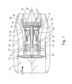
- the gas turbine engine 10 is an example of a turbomachine to which the invention may find application. However, it will be understood from the following that the invention can be used with other turbomachinery as well.
- the engine 10 is conventionally formed and includes in the flow direction one after another an air inlet 11, a fan 12 circulating in a housing, an intermediate pressure compressor 13, a high pressure compressor 14, combustion chambers 15, a high pressure turbine 16, an intermediate pressure turbine 17 and a low pressure turbine 18 and an exhaust nozzle 19, which are all arranged around a central engine axis 1.
- the intermediate pressure compressor 13 and the high pressure compressor 14 each include a plurality of stages, each of which includes a circumferentially extending array of fixed stationary vanes 20, commonly referred to as stator vanes, that radially inwardly from the engine casing 21 in an annular flow passage through the compressors 13, 14 protrude.
- the compressors further include an array of compressor blades 22 projecting radially outwardly from a rotatable drum or disc 26 coupled to hubs 27 of the high pressure turbine 16 and the intermediate pressure turbine 17, respectively.
- the turbine sections 16, 17, 18 have similar stages, comprising an array of fixed vanes 23 projecting radially inward from the housing 21 into the annular flow passage through the turbines 16, 17, 18, and a downstream array of turbine blades 24 projecting outwardly from a rotatable hub 27.
- the compressor drum or compressor disk 26 and the vanes 22 disposed thereon and the turbine rotor hub 27 and the turbine blades 24 disposed thereon rotate about the engine axis 1 during operation.
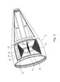
- the reference numeral 28 shows an outlet cone. This one is in the Fig. 2 and 3 shown in more detail.
- the outlet cone includes a in Fig. 2 Installation area shown on the left, which is adjacent to a turbine outlet, and a substantially conical central area (right area in Fig. 2 ). The representation of an end region has been omitted.
- the outlet cone 28 includes an outer wall 29 which is provided with a plurality of recesses. On the inside of the outer wall 29, a honeycomb structure layer 30 is arranged, to which an inner wall 31 connects, which also has sound passage recesses.
- the left area according to Fig. 2 is provided with a plurality of radially encircling annular chambers 32, which are inclined to the central axis (engine axis) 1 and serve in particular for damping low-frequency sound vibrations.
- the individual annular chambers 32 are in the circumferential direction, as is the case Fig. 3 can be seen, divided by partition walls 33 (plate-like wall elements) into individual chambers 34, which are thus arranged segment-like around the circumference and form the ring structure of the annular chamber 32.
- the partition walls 33 are each in the form of a three-dimensional structure, which, as in particular Fig. 5 can be seen, raised areas 35 and recessed areas 36 has.
- the partition wall 33 is made of a sheet-like material by forming or similar molding processes.
- the raised portions 35 and the recessed portions 36 form a structure similar to an egg carton in which chicken eggs are insertable.
- the partition wall 33 is wavy or sinusoidal, thus having a pattern of protrusions and recessed areas. This results in a three-dimensional wavy structure.
- fastening tabs 37 are formed, which protrude beyond the edges and serve for welding fastening.
- the Fig. 6 shows a representation from which arise the resulting thermal expansions and contractions loads.
- the dashed lines show the resulting shape changes compared to the solid lines.
- the arrow A shows that at this corner results in a reduction of the angle.
- At the adjacent corner results in an increase in the angle.
- the arrow C on the opposite wall shows a reduction of the angle, while the arrow D represents an increase of the angle.
- the arrows E and F show the loads applied by shear forces.
- partition wall according to the invention (plate-like wall element) can be deformed in different ways without introducing forces which would exceed the material strength and lead to component failure.
Landscapes
- Engineering & Computer Science (AREA)
- Chemical & Material Sciences (AREA)
- Combustion & Propulsion (AREA)
- Mechanical Engineering (AREA)
- General Engineering & Computer Science (AREA)
- Supercharger (AREA)
- Structures Of Non-Positive Displacement Pumps (AREA)
Abstract
Description
- Die Erfindung bezieht sich auf einen Gasturbinenabgaskonus, welcher am Ausströmbereich einer Gasturbine angeordnet ist.
- Bei Gasturbinen für Flugzeugtriebwerken ist es erforderlich, das Geräuschniveau zu senken. Zu diesem Zweck sind auch unterschiedliche Maßnahmen bekannt, um das aus einer Abströmdüse stromab der Turbine austretende Gasstrahlgeräusch zu minimieren.
- Aus dem Stand der Technik ist es bekannt, niedrige Frequenzen, die sich insbesondere bei Triebwerken mit Magerverbrennung ergeben, zu dämpfen. Eine Geräuschdämpfung erfolgt dabei über einen Helmholtz-Resonator. Es ist bekannt, in dem Anströmbereich des Auslasskonus einen derartigen Helmholtz-Resonator auszubilden, während der stromab liegende Endbereich des Auslasskonus lediglich als geometrischer Körper ausgebildet ist. Bekannte Helmholtz-Resonatoren werden dabei als System von radialen Wänden und inneren zylindrischen Führungen ausgestaltet und in Abhängigkeit von den Frequenzen dimensioniert.
- Bei den bekannten Konstruktionen erweist es sich als nachteilig, dass diese im Hinblick auf die auftretenden Gastemperaturen mechanisch stark belastet sind und deshalb Verstärkungselemente erfordern. Dies führt zu einer ein relativ hohes Gewicht aufweisenden Konstruktion, auch bedingt durch unterschiedliche Wandungen und Versteifungselemente. Zusätzlich ergibt sich eine sehr aufwendige Fertigung. Die Herstellungskosten werden auch noch durch interne Akustik-Maßnahmen (Perforationen oder Ähnliches) erhöht. Auch die axiale Länge eines derartigen Resonators erfordert einen erheblichen Bauraum und bringt zusätzliches Gewicht. Weiterhin ist eine Geräuschabdichtung zwischen den einzelnen Hohlräumen nicht gegeben.
- Zusätzlich zu den aus dem Stand der Technik bekannten Problemen hat es sich bei Gasturbinen als wünschenswert erwiesen, auch die niedrigerfrequenten Schwingungen der Brennkammer, zusätzlich zu den höheren Schwingungen der Turbine, ausreichend zu dämpfen. Hierfür sind tiefe, große Kammern erforderlich, welche durch axiradiale Trennwände unterteilt sind. Die äußeren, perforierten Wandungen eines Gasturbinenabgaskonus sind sehr hohen Gastemperaturen ausgesetzt, während die im Inneren des Auslasskonus installierten Trennwände oder Strukturen weitaus geringere Temperaturen aufweisen. Aus diesem Grund ergibt sich die Thematik der thermischen Expansion bzw. Kontraktion. Dies führt zu erheblichen Bewegungen der Grenzbereiche zwischen den einzelnen Bauelementen, wodurch sich eine nicht unerhebliche Gefahr von Rissbildung und Bauteilversagen ergibt.
- Eine unterschiedliche thermische Expansion oder Kontraktion der Trennwände sowie der betroffenen Bauteile führt zu einer nicht-linearen und nicht-gleichen Expansion und/oder Kontraktion der Trennwände (axiradiale Wandungen). Dies führt zu Verwindungen und Verformungen der Wandungen aufgrund der eingebrachten Scherkräfte. Durch die sehr hohen Temperaturunterschiede ist die relative Differential-Expansion oder Kontraktion sehr groß und führt zu plastischen Verformungen der Wandungen und zu einem Gesamtversagen der Struktur. Die Verstärkung der axiradialen Wandungen löst dieses Problem nicht, da Verstärkungen zu weiteren Bewegungsproblemen führen, welche zu Rissen, Brüchen oder einem Versagen von Schweißnähten an der Umfangsstruktur (Innenwandungen und Außenwandungen des Auslasskonus) führen.
- Der Erfindung liegt die Aufgabe zugrunde, einen Gasturbinenabgaskonus der eingangs genannten Art zu schaffen, welcher die Nachteile des Standes der Technik vermeidet und hohe thermische Expansionen oder Kontraktionen erlaubt.
- Erfindungsgemäß wird die Aufgabe durch die Merkmalskombination des Anspruchs gelöst, die Unteransprüche zeigen weitere vorteilhafte Ausgestaltungen der Erfindung.
- Erfindungsgemäß ist somit ein Gasturbinenabgaskonus geschaffen, welcher eine Außenwandung mit einer Vielzahl von Ausnehmungen aufweist, wobei sich entlang der Innenseite der Außenwandung eine Innenwandung erstreckt. Zwischen der Außenwandung und der Innenwandung ist eine Wabenstrukturschicht angeordnet. Durch geeignete Ausnehmungen können die Schalldruckwellen in den Innenraum des Auslasskonus vordringen. Zur Dämpfung insbesondere der niedrigfrequenten Schwingungen sind angrenzend an die Innenwandung eine oder mehrere zu einer zentrischen Achse zentrierte Ringkammern vorgesehen, welche in Umfangsrichtung in einzelne Kammern unterteilt sind. Erfindungsgemäß ist dabei vorgesehen, dass die Unterteilung der jeweiligen Ringkammer in einzelne in Umfangsrichtung angeordnete Kammern durch zumindest eine Trennwand erfolgt, die aus einem blechartigen Material gefertigt ist. Die Trennwand umfasst eine Vielzahl von erhabenen und/oder rückgesetzten Bereichen, die in einer gleichmäßigen Anordnung durch Umformung des blechartigen Materials gebildet sind und eine 3-dimensionale Wellenstruktur bildet. Es ergibt sich somit eine elliptisch-paraboloide Struktur, ähnlich einer eierkartonartigen Anordnung, wobei die erhabenen und die rückgesetzten Bereiche jeweils in zueinander parallelen Linien angeordnet sein können. Es ist jedoch auch möglich, die einzelnen Linien jeweils zueinander zu versetzen, so dass sich eine dichteste Packung ähnlich einer Bienenwabenstruktur ergibt.
- Durch die erfindungsgemäß vorgesehenen erhabenen und rückgesetzten Bereiche, welche eine dreidimensionale, regelmäßige Struktur oder ein dreidimensionales, regelmäßiges Muster bilden, ist die Trennwand in der Lage, starke thermische Expansionen an einzelnen Bereichen der Trennwand aufzunehmen. So können einzelne Randbereiche in entgegengesetzten Richtungen thermisch expandiert oder kontrahiert werden, ohne dass die Gesamtstruktur hierdurch beschädigt würde. Dies erweist sich insbesondere an den Randbereichen, an welchen die Trennwand mit weiteren Strukturelementen verbunden ist, als besonders vorteilhaft, da dort keine Rissgefahr durch Überlastung auftritt. Vielmehr verformt sich die dreidimensionale Trennwand in sich selbst so, dass keine durch thermische Effekte hervorgerufenen Kräfte auf benachbarte Bauelemente übertragen werden. Die Trennwand weist somit eine reduzierte Steifigkeit auf und besitzt damit die Möglichkeit, Fährkräfte zu übertragen. Hierdurch ergibt sich eine kontrollierte Reduktion der lokalen Stabilität, welche jedoch die Funktionsfähigkeit und die Gesamtstabilität der Trennwand nicht beeinträchtigt. Es ergibt sich somit die Möglichkeit, unterschiedliche Versetzungen der axiradialen Kanten der Trennwand ohne Einbringung von zu großen Scherkräften zu ermöglichen.
- Die erfindungsgemäße Trennwand ist bevorzugterweise durch einen Umformvorgang hergestellt, beispielsweise durch Tiefziehen oder superplastische Deformation. Weiterhin ist es erfindungsgemäß möglich, Schweißverbindungen an ausgewählten Bereichen der Kanten der Trennwand vorzusehen, beispielsweise jeweils an den erhabenen Bereichen oder an den rückgesetzten Bereichen. Dies beeinträchtigt nicht die Verformbarkeit der Trennwand. Erfindungsgemäß ist es auch möglich, die Trennwand mittels eines Lötverfahrens oder eines anderen Fügeverfahrens mit den Strukturelementen des Auslasskonus zu verbinden. Erfindungsgemäß ist somit eine Lösung geschaffen, welche unter Verwendung einer einfachen Struktur der Trennwand bei geringem Gewicht und kostengünstiger Herstellbarkeit die Nachteile des Standes der Technik vermeidet.
- In günstiger Ausgestaltung ist die erfindungsgemäße Trennwand so ausgebildet, dass diese im Schnitt wellenförmig oder sägezahnförmig oder sinusoid ist oder durch sich kreuzende Wellenformen gebildet ist. In jedem Fall ergibt sich eine eikartonähnliche Gesamtgestalt, welche unterschiedlichste lokale Expansionen oder Kontraktionen durch thermische Effekte ermöglicht und gleichzeitig geräuschdicht ist.
- Im Folgenden wird die Erfindung anhand eines Ausführungsbeispiels in Verbindung mit der Zeichnung beschrieben. Dabei zeigt:
- Fig. 1
- eine schematische Darstellung eines Gasturbinentriebwerks gemäß der vorliegenden Erfindung,
- Fig. 2
- eine vereinfachte Axialschnittansicht eines erfindungsgemäßen Auslasskonus,
- Fig. 3
- eine Ansicht des Auslasskonus in perspektivischer Ansicht, teils im Schnitt,
- Fig. 4
- eine Teilansicht einer erfindungsgemäßen Trennwand bzw. eines plattenartigen Wandelements,
- Fig. 5
- eine weitere Ansicht der Trennwand bzw. des plattenartigen Wandelements in perspektivischer Ansicht, und
- Fig. 6
- eine vereinfachte Darstellung der durch thermische Effekte auftretenden Belastungen.
- Das Gasturbinentriebwerk 10 gemäß
Fig. 1 ist ein Beispiel einer Turbomaschine, bei der die Erfindung Anwendung finden kann. Aus dem Folgenden wird jedoch klar, dass die Erfindung auch bei anderen Turbomaschinen verwendet werden kann. Das Triebwerk 10 ist in herkömmlicher Weise ausgebildet und umfasst in Strömungsrichtung hintereinander einen Lufteinlass 11, einen in einem Gehäuse umlaufenden Fan 12, einen Zwischendruckkompressor 13, einen Hochdruckkompressor 14, Brennkammern 15, eine Hochdruckturbine 16, eine Zwischendruckturbine 17 und eine Niederdruckturbine 18 sowie eine Abgasdüse 19, die sämtlich um eine zentrale Triebwerksachse 1 angeordnet sind. - Der Zwischendruckkompressor 13 und der Hochdruckkompressor 14 umfassen jeweils mehrere Stufen, von denen jede eine in Umfangsrichtung verlaufende Anordnung fester stationärer Leitschaufeln 20 aufweist, die allgemein als Statorschaufeln bezeichnet werden und die radial nach innen vom Triebwerksgehäuse 21 in einem ringförmigen Strömungskanal durch die Kompressoren 13, 14 vorstehen. Die Kompressoren weisen weiter eine Anordnung von Kompressorlaufschaufeln 22 auf, die radial nach außen von einer drehbaren Trommel oder Scheibe 26 vorstehen, die mit Naben 27 der Hochdruckturbine 16 bzw. der Zwischendruckturbine 17 gekoppelt sind.
- Die Turbinenabschnitte 16, 17, 18 weisen ähnliche Stufen auf, umfassend eine Anordnung von festen Leitschaufeln 23, die radial nach innen vom Gehäuse 21 in den ringförmigen Strömungskanal durch die Turbinen 16, 17, 18 vorstehen, und eine nachfolgende Anordnung von Turbinenschaufeln 24, die nach außen von einer drehbaren Nabe 27 vorstehen. Die Kompressortrommel oder Kompressorscheibe 26 und die darauf angeordneten Schaufeln 22 sowie die Turbinenrotornabe 27 und die darauf angeordneten Turbinenlaufschaufeln 24 drehen sich im Betrieb um die Triebwerksachse 1.
- Das Bezugszeichen 28 zeigt einen Auslasskonus. Dieser ist in den
Fig. 2 und3 näher dargestellt. Der Auslasskonus umfasst einen inFig. 2 links dargestellten Installationsbereich, welcher an einen Turbinenauslass angrenzt, sowie einen im Wesentlichen konischen Mittelbereich (rechter Bereich inFig. 2 ). Auf die Darstellung eines Endbereichs wurde verzichtet. - Der Auslasskonus 28 umfasst eine Außenwandung 29, welche mit einer Vielzahl von Ausnehmungen versehen ist. An der Innenseite der Außenwandung 29 ist eine Wabenstrukturschicht 30 angeordnet, an welche sich eine Innenwandung 31 anschließt, welche ebenfalls Schalldurchtrittsausnehmungen aufweist.
- Insbesondere der linke Bereich gemäß
Fig. 2 ist mit mehreren radial umlaufenden Ringkammern 32 versehen, welche zur zentrischen Achse (Triebwerksachse) 1 geneigt sind und insbesondere zur Dämpfung niedrigfrequenter Schallschwingungen dienen. Die einzelnen Ringkammern 32 sind in Umfangsrichtung, so wie dies ausFig. 3 ersichtlich ist, durch Trennwände 33 (plattenartige Wandelemente) in einzelne Kammern 34 unterteilt, welche somit segmentartig um den Umfang angeordnet sind und die Ringstruktur der Ringkammer 32 bilden. - Erfindungsgemäß sind die Trennwände 33 jeweils in Form einer dreidimensionalen Struktur ausgebildet, welche, wie insbesondere aus
Fig. 5 ersichtlich ist, erhabene Bereiche 35 und rückgesetzte Bereiche 36 aufweist. Die Trennwand 33 ist aus einem blechartigen Material durch Umformung oder ähnliche formgebende Verfahren hergestellt. Die erhabenen Bereiche 35 und die rückgesetzten Bereiche 36 bilden eine Struktur ähnlich einem Eierkarton, in welchen Hühnereier einlegbar sind. In der Schnittansicht ist die Trennwand 33 wellenförmig oder sinusoid, sie weist somit ein Muster aus Erhebungen und rückgesetzten Bereichen auf. Es ergibt sich somit eine dreidimensionale gewellte Struktur. An den Kantenbereichen (Randbereichen), an welchen die Trennwand 33 mit Strukturelementen des Auslasskonus zu verbinden ist, sind Befestigungslaschen 37 ausgebildet, welche über die Kanten vorstehen und zur Schweißbefestigung dienen. - Die
Fig. 6 zeigt eine Darstellung, aus welcher sich die durch thermische Ausdehnungen und Kontraktionen ergebenden Belastungen ergeben. Dabei zeigen die gestrichelten Linien im Vergleich zu den durchgezogenen Linien die sich ergebenden Formänderungen. Der Pfeil A zeigt, dass sich an dieser Ecke eine Verkleinerung des Winkels ergibt. An der benachbarten Ecke (Pfeil B) ergibt sich eine Vergrößerung des Winkels. Der Pfeil C an der gegenüberliegenden Wandung zeigt eine Verkleinerung des Winkels, während der Pfeil D eine Vergrößerung des Winkels darstellt. Die Pfeile E und F zeigen die durch Scherkräfte aufgebrachten Belastungen. - Es ist somit ersichtlich, dass die erfindungsgemäße Trennwand (plattenartiges Wandelement) in unterschiedlicher Weise verformbar ist, ohne dass hierdurch Kräfte eingebracht werden, welche die Materialfestigkeit übersteigen und zu einem Bauteilversagen führen würden.
-
- 1
- Triebwerksachse / zentrische Achse
- 10
- Gasturbinentriebwerk
- 11
- Lufteinlass
- 12
- im Gehäuse umlaufender Fan
- 13
- Zwischendruckkompressor
- 14
- Hochdruckkompressor
- 15
- Brennkammern
- 16
- Hochdruckturbine
- 17
- Zwischendruckturbine
- 18
- Niederdruckturbine
- 19
- Abgasdüse
- 20
- Leitschaufeln
- 21
- Triebwerksgehäuse
- 22
- Kompressorlaufschaufeln
- 23
- Leitschaufeln
- 24
- Turbinenschaufeln
- 26
- Kompressortrommel oder -Scheibe
- 27
- Turbinenrotornabe
- 28
- Auslasskonus
- 29
- Außenwandung
- 30
- Wabenstrukturschicht
- 31
- Innenwandung
- 32
- Ringkammer
- 33
- Trennwand / plattenartiges Wandelement
- 34
- Kammer
- 35
- erhabener Bereich
- 36
- rückgesetzter Bereich
- 37
- Befestigungslasche
Claims (10)
- Gasturbinenabgaskonus mit einer Außenwandung (29), welche mit einer Vielzahl von Ausnehmungen versehen ist, mit einer an der Innenseite der Außenwandung (29) angeordneten Wabenstrukturschicht (30), welche sich entlang der Innenseite der Außenwandung (29) erstreckt, mit einer sich im Wesentlichen parallel zur Außenwandung (29) erstreckenden, mit der Wabenstruktur (30) verbundenen Innenwandung (31), mit zumindest einer an die Innenwandung (31) angrenzenden und zu einer zentrischen Achse (1) zentrierten Ringkammer (32), wobei die Innenwandung (31) mit Durchgangsausnehmungen versehen ist, welche den Bereich der Wabenstruktur (30) mit der Ringkammer (32) verbinden, wobei die Ringkammer (32) in Umfangsrichtung mittels zumindest einer Trennwand (33) in mehrere Kammern (34) unterteilt ist, wobei die Trennwand (33) aus einem blechartigen Material gefertigt ist und eine Vielzahl von erhabenen (35) und/oder rückgesetzten (36) Bereichen umfasst, die in einer gleichmäßigen Anordnung durch Umformung des blechartigen Materials gebildet sind.
- Gasturbinenabgaskonus nach Anspruch 1, dadurch gekennzeichnet, dass die Trennwand (33) in Form einer dreidimensionalen Struktur mit einem regelmäßigen Muster mit erhabenen (35) und rückgesetzten (36) Bereichen ausgebildet ist und insbesondere im Schnitt wellenförmig oder sägezahnförmig oder sinusoid ist und/oder dass die dreidimensionale Struktur der Trennwand (33) durch kreuzende Wellenformen gebildet ist.
- Gasturbinenabgaskonus nach Anspruch 1 oder 2, dadurch gekennzeichnet, dass die Trennwand (33) so ausgebildet ist, dass thermische Expansionen in unterschiedlichen Richtungen möglich sind.
- Gasturbinenabgaskonus nach einem der Ansprüche 1 bis 3, dadurch gekennzeichnet, dass an zumindest einer Seite der Trennwand seitliche Befestigungslaschen (37) ausgebildet sind.
- Gasturbinenabgaskonus nach Anspruch 4, dadurch gekennzeichnet, dass eine Befestigung der Befestigungslaschen (37) an tragenden Strukturen durch Punktschweißen oder Punktfügen erfolgt.
- Plattenartiges Wandelement, insbesondere für eine innenliegende Struktur eines Auslasskonus (28) einer Fluggasturbine, wobei das Wandelement (33) aus einem blechartigen Material gefertigt ist und eine Vielzahl von erhabenen (35) und/oder rückgesetzten (36) Bereichen umfasst, die in einer gleichmäßigen Anordnung durch Umformung des blechartigen Materials gebildet sind.
- Wandelement nach Anspruch 6, dadurch gekennzeichnet, dass die Trennwand (33) in Form einer dreidimensionalen Struktur mit einem regelmäßigen Muster mit erhabenen (35) und rückgesetzten (36) Bereichen ausgebildet ist und insbesondere im Schnitt wellenförmig oder sägezahnförmig oder sinusoid ist und/oder dass die dreidimensionale Struktur der Trennwand (33) durch kreuzende Wellenformen gebildet ist.
- Wandelement nach Anspruch 6 oder 7, dadurch gekennzeichnet, dass das Wandelement (33) so ausgebildet ist, dass thermische Expansionen in unterschiedlichen Richtungen möglich sind.
- Wandelement nach einem der Ansprüche 6 bis 8, dadurch gekennzeichnet, dass an zumindest einer Seite des Wandelements (33) seitliche Befestigungslaschen (37) ausgebildet sind.
- Wandelement nach einem der Ansprüche 6 bis 9, dadurch gekennzeichnet, dass eine Befestigung der Befestigungslaschen (37) an tragenden Strukturen durch Punktschweißen oder Punktfügen erfolgt.
Applications Claiming Priority (1)
| Application Number | Priority Date | Filing Date | Title |
|---|---|---|---|
| DE102011108533A DE102011108533A1 (de) | 2011-07-26 | 2011-07-26 | Abgasturbinenkonus mit dreidimensional profilierter Trennwand sowie plattenartiges Wandelement |
Publications (3)
| Publication Number | Publication Date |
|---|---|
| EP2551507A2 true EP2551507A2 (de) | 2013-01-30 |
| EP2551507A3 EP2551507A3 (de) | 2017-10-04 |
| EP2551507B1 EP2551507B1 (de) | 2020-06-03 |
Family
ID=46551354
Family Applications (1)
| Application Number | Title | Priority Date | Filing Date |
|---|---|---|---|
| EP12005210.5A Active EP2551507B1 (de) | 2011-07-26 | 2012-07-16 | Abgasturbinenkonus mit dreidimensional profilierter Trennwand sowie plattenartiges Wandelement |
Country Status (3)
| Country | Link |
|---|---|
| US (1) | US8479877B2 (de) |
| EP (1) | EP2551507B1 (de) |
| DE (1) | DE102011108533A1 (de) |
Cited By (1)
| Publication number | Priority date | Publication date | Assignee | Title |
|---|---|---|---|---|
| EP3839238A1 (de) * | 2019-12-20 | 2021-06-23 | Airbus Operations (S.A.S.) | Ausgangskonus einer antriebseinheit eines luftfahrzeugs, der ein akustisches verarbeitungssystem mit mindestens zwei freiheitsgraden bildet |
Families Citing this family (8)
| Publication number | Priority date | Publication date | Assignee | Title |
|---|---|---|---|---|
| DE102011008921A1 (de) * | 2011-01-19 | 2012-07-19 | Rolls-Royce Deutschland Ltd & Co Kg | Gasturbinenabgaskonus |
| GB201301702D0 (en) * | 2013-01-31 | 2013-03-20 | Rolls Royce Plc | Exhaust cone |
| US9551239B2 (en) * | 2015-04-22 | 2017-01-24 | Rohr, Inc. | Exhaust assembly center body |
| US11136942B2 (en) * | 2018-09-14 | 2021-10-05 | Rohr, Inc. | Acoustic deep cavity centerbody |
| US11434778B2 (en) * | 2019-03-11 | 2022-09-06 | Hamilton Sundstrand Corporation | Integrated tail cone and mounted generator acoustic suppression |
| US11319895B2 (en) * | 2019-03-15 | 2022-05-03 | Hamilton Sundstrand Corporation | Integrated tail cone and mounted generator |
| FR3114848B1 (fr) * | 2020-10-07 | 2023-11-24 | Safran Ceram | Cône d’échappement pour une turbomachine |
| US11976597B2 (en) * | 2021-09-13 | 2024-05-07 | Rohr, Inc. | Low-frequency acoustic center body |
Family Cites Families (16)
| Publication number | Priority date | Publication date | Assignee | Title |
|---|---|---|---|---|
| US3507355A (en) * | 1969-05-22 | 1970-04-21 | Rohr Corp | Multi-layer face material for sound absorptive duct lining material |
| US3948346A (en) * | 1974-04-02 | 1976-04-06 | Mcdonnell Douglas Corporation | Multi-layered acoustic liner |
| US4064961A (en) * | 1976-04-05 | 1977-12-27 | Rohr Industries, Incorporated | Slanted cavity resonator |
| US4137992A (en) * | 1976-12-30 | 1979-02-06 | The Boeing Company | Turbojet engine nozzle for attenuating core and turbine noise |
| FR2396868A1 (fr) * | 1977-07-07 | 1979-02-02 | Snecma | Garniture insonorisante pour paroi interne de conduit de gaz, notamment de conduit de turboreacteur |
| US5782082A (en) * | 1996-06-13 | 1998-07-21 | The Boeing Company | Aircraft engine acoustic liner |
| HU223037B1 (hu) * | 2000-04-17 | 2004-03-01 | Rieter Automotive (International) Ag | Eljárás akusztikailag hatékony fóliarakat előállítására |
| US6973790B2 (en) * | 2000-12-06 | 2005-12-13 | Mitsubishi Heavy Industries, Ltd. | Gas turbine combustor, gas turbine, and jet engine |
| US6615576B2 (en) * | 2001-03-29 | 2003-09-09 | Honeywell International Inc. | Tortuous path quiet exhaust eductor system |
| ES2224807B1 (es) * | 2002-08-14 | 2007-05-01 | Sener, Ingenieria Y Sistemas, S.A. | Conducto de reduccion de ruido para componentes estaticos de motores aeronauticos. |
| US6966402B2 (en) * | 2003-06-02 | 2005-11-22 | Dana Corporation | Acoustical heat shield |
| US7267297B2 (en) * | 2004-09-02 | 2007-09-11 | The Boeing Company | Integrated axially varying engine muffler, and associated methods and systems |
| US7784283B2 (en) * | 2006-05-03 | 2010-08-31 | Rohr, Inc. | Sound-absorbing exhaust nozzle center plug |
| US7866440B2 (en) * | 2006-07-21 | 2011-01-11 | Rohr, Inc. | System for joining acoustic cellular panel sections in edge-to-edge relation |
| FR2912186B1 (fr) * | 2007-02-01 | 2013-07-05 | Airbus France | Dispositif de traitement acoustique des bruits de turbine et de combustion |
| US8025122B2 (en) * | 2008-11-06 | 2011-09-27 | The Boeing Company | Acoustically treated exhaust centerbody for jet engines and associated methods |
-
2011
- 2011-07-26 DE DE102011108533A patent/DE102011108533A1/de not_active Withdrawn
-
2012
- 2012-07-16 EP EP12005210.5A patent/EP2551507B1/de active Active
- 2012-07-23 US US13/555,790 patent/US8479877B2/en active Active
Non-Patent Citations (1)
| Title |
|---|
| None |
Cited By (2)
| Publication number | Priority date | Publication date | Assignee | Title |
|---|---|---|---|---|
| EP3839238A1 (de) * | 2019-12-20 | 2021-06-23 | Airbus Operations (S.A.S.) | Ausgangskonus einer antriebseinheit eines luftfahrzeugs, der ein akustisches verarbeitungssystem mit mindestens zwei freiheitsgraden bildet |
| FR3105551A1 (fr) * | 2019-12-20 | 2021-06-25 | Airbus Operations | Cône de sortie d’un ensemble propulsif d’aéronef formant un système de traitement acoustique à au moins deux degrés de liberté |
Also Published As
| Publication number | Publication date |
|---|---|
| EP2551507B1 (de) | 2020-06-03 |
| DE102011108533A1 (de) | 2013-01-31 |
| US8479877B2 (en) | 2013-07-09 |
| US20130025962A1 (en) | 2013-01-31 |
| EP2551507A3 (de) | 2017-10-04 |
Similar Documents
| Publication | Publication Date | Title |
|---|---|---|
| EP2551507B1 (de) | Abgasturbinenkonus mit dreidimensional profilierter Trennwand sowie plattenartiges Wandelement | |
| EP2665898B1 (de) | Gasturbinenabgaskonus | |
| EP2665899B1 (de) | Verfahren zur herstellung eines schallabsorbers, insbesondere für einen gasturbinenabgaskonus | |
| EP2886961B1 (de) | Unterlegscheibe einer Brennkammerschindel einer Gasturbine | |
| DE102011008695A1 (de) | Verfahren zum generativen Herstellen eines Bauelements mit einer integrierten Dämpfung für eine Strömungsmaschine und generativ hergestelltes Bauelement mit einer integrierten Dämpfung für eine Strömungsmaschine | |
| DE102007042767A1 (de) | Mehrschichtiger Abschirmungsring für einen Flugantrieb | |
| EP2881552B1 (de) | Fluggasturbine mit einem Kerntriebwerksgehäuse mit Kühlluftröhren | |
| EP2407659A2 (de) | Gasturbinenabgaskonus | |
| EP2665904B1 (de) | Schallabsorber für einen gasturbinenabgaskonus und verfahren zu dessen herstellung | |
| EP3199758B1 (de) | Rotor in blisk- oder bling-bauweise eines flugtriebwerks | |
| EP2620628B1 (de) | Triebwerksgehäuse einer Fluggasturbine mit Schalldämpfungselementen im Fan-Einströmbereich | |
| EP2526263B1 (de) | Gehäusesystem für eine axialströmungsmaschine | |
| WO2021148213A1 (de) | Resonatorring für brennkammersysteme | |
| EP3034944A1 (de) | Gasturbinenbrennkammer mit veränderter wandstärke | |
| EP2871418B1 (de) | Gasturbinenbrennkammer sowie Verfahren zu deren Herstellung | |
| EP3514333B1 (de) | Rotorschaufeldeckband für eine strömungsmaschine, rotorschaufel, verfahren zum herstellen eines rotorschaufeldeckbands und einer rotorschaufel | |
| EP2848770B1 (de) | Laufradschaufel einer axialen Strömungsmaschine und Dämpfungselement | |
| DE102016206188A1 (de) | Brennkammerschindel einer Gasturbine | |
| EP3572622B1 (de) | Turbinenzwischengehäuse mit spezifisch ausgebildeter ringraumkontur | |
| DE102011103158A1 (de) | Fluggasturbine mit einer Lagerung eines thermischen Enteisungs-Rohrelements | |
| EP0292705B1 (de) | Spiralgehäuse für Turbo-Arbeitsmaschinen | |
| DE102015206095A1 (de) | Fluggasturbine mit variabler Nebenstromdüse | |
| WO2021110191A1 (de) | Dichtungsträger für eine turbomaschine mit schlitzartigen öffnungen im dichtungskörper |
Legal Events
| Date | Code | Title | Description |
|---|---|---|---|
| PUAI | Public reference made under article 153(3) epc to a published international application that has entered the european phase |
Free format text: ORIGINAL CODE: 0009012 |
|
| AK | Designated contracting states |
Kind code of ref document: A2 Designated state(s): AL AT BE BG CH CY CZ DE DK EE ES FI FR GB GR HR HU IE IS IT LI LT LU LV MC MK MT NL NO PL PT RO RS SE SI SK SM TR |
|
| AX | Request for extension of the european patent |
Extension state: BA ME |
|
| PUAL | Search report despatched |
Free format text: ORIGINAL CODE: 0009013 |
|
| AK | Designated contracting states |
Kind code of ref document: A3 Designated state(s): AL AT BE BG CH CY CZ DE DK EE ES FI FR GB GR HR HU IE IS IT LI LT LU LV MC MK MT NL NO PL PT RO RS SE SI SK SM TR |
|
| AX | Request for extension of the european patent |
Extension state: BA ME |
|
| RIC1 | Information provided on ipc code assigned before grant |
Ipc: F02K 1/82 20060101AFI20170830BHEP Ipc: F02K 1/04 20060101ALI20170830BHEP |
|
| STAA | Information on the status of an ep patent application or granted ep patent |
Free format text: STATUS: REQUEST FOR EXAMINATION WAS MADE |
|
| 17P | Request for examination filed |
Effective date: 20180130 |
|
| RBV | Designated contracting states (corrected) |
Designated state(s): AL AT BE BG CH CY CZ DE DK EE ES FI FR GB GR HR HU IE IS IT LI LT LU LV MC MK MT NL NO PL PT RO RS SE SI SK SM TR |
|
| STAA | Information on the status of an ep patent application or granted ep patent |
Free format text: STATUS: EXAMINATION IS IN PROGRESS |
|
| 17Q | First examination report despatched |
Effective date: 20181214 |
|
| GRAP | Despatch of communication of intention to grant a patent |
Free format text: ORIGINAL CODE: EPIDOSNIGR1 |
|
| STAA | Information on the status of an ep patent application or granted ep patent |
Free format text: STATUS: GRANT OF PATENT IS INTENDED |
|
| INTG | Intention to grant announced |
Effective date: 20191216 |
|
| GRAS | Grant fee paid |
Free format text: ORIGINAL CODE: EPIDOSNIGR3 |
|
| GRAA | (expected) grant |
Free format text: ORIGINAL CODE: 0009210 |
|
| STAA | Information on the status of an ep patent application or granted ep patent |
Free format text: STATUS: THE PATENT HAS BEEN GRANTED |
|
| AK | Designated contracting states |
Kind code of ref document: B1 Designated state(s): AL AT BE BG CH CY CZ DE DK EE ES FI FR GB GR HR HU IE IS IT LI LT LU LV MC MK MT NL NO PL PT RO RS SE SI SK SM TR |
|
| REG | Reference to a national code |
Ref country code: GB Ref legal event code: FG4D Free format text: NOT ENGLISH |
|
| RIN1 | Information on inventor provided before grant (corrected) |
Inventor name: TODOROVIC, PREDRAG |
|
| REG | Reference to a national code |
Ref country code: CH Ref legal event code: EP Ref country code: AT Ref legal event code: REF Ref document number: 1277257 Country of ref document: AT Kind code of ref document: T Effective date: 20200615 |
|
| REG | Reference to a national code |
Ref country code: DE Ref legal event code: R096 Ref document number: 502012016106 Country of ref document: DE |
|
| REG | Reference to a national code |
Ref country code: LT Ref legal event code: MG4D |
|
| PG25 | Lapsed in a contracting state [announced via postgrant information from national office to epo] |
Ref country code: SE Free format text: LAPSE BECAUSE OF FAILURE TO SUBMIT A TRANSLATION OF THE DESCRIPTION OR TO PAY THE FEE WITHIN THE PRESCRIBED TIME-LIMIT Effective date: 20200603 Ref country code: FI Free format text: LAPSE BECAUSE OF FAILURE TO SUBMIT A TRANSLATION OF THE DESCRIPTION OR TO PAY THE FEE WITHIN THE PRESCRIBED TIME-LIMIT Effective date: 20200603 Ref country code: GR Free format text: LAPSE BECAUSE OF FAILURE TO SUBMIT A TRANSLATION OF THE DESCRIPTION OR TO PAY THE FEE WITHIN THE PRESCRIBED TIME-LIMIT Effective date: 20200904 Ref country code: NO Free format text: LAPSE BECAUSE OF FAILURE TO SUBMIT A TRANSLATION OF THE DESCRIPTION OR TO PAY THE FEE WITHIN THE PRESCRIBED TIME-LIMIT Effective date: 20200903 Ref country code: LT Free format text: LAPSE BECAUSE OF FAILURE TO SUBMIT A TRANSLATION OF THE DESCRIPTION OR TO PAY THE FEE WITHIN THE PRESCRIBED TIME-LIMIT Effective date: 20200603 |
|
| PGFP | Annual fee paid to national office [announced via postgrant information from national office to epo] |
Ref country code: DE Payment date: 20200928 Year of fee payment: 9 Ref country code: FR Payment date: 20200728 Year of fee payment: 9 |
|
| REG | Reference to a national code |
Ref country code: NL Ref legal event code: MP Effective date: 20200603 |
|
| PG25 | Lapsed in a contracting state [announced via postgrant information from national office to epo] |
Ref country code: BG Free format text: LAPSE BECAUSE OF FAILURE TO SUBMIT A TRANSLATION OF THE DESCRIPTION OR TO PAY THE FEE WITHIN THE PRESCRIBED TIME-LIMIT Effective date: 20200903 Ref country code: LV Free format text: LAPSE BECAUSE OF FAILURE TO SUBMIT A TRANSLATION OF THE DESCRIPTION OR TO PAY THE FEE WITHIN THE PRESCRIBED TIME-LIMIT Effective date: 20200603 Ref country code: RS Free format text: LAPSE BECAUSE OF FAILURE TO SUBMIT A TRANSLATION OF THE DESCRIPTION OR TO PAY THE FEE WITHIN THE PRESCRIBED TIME-LIMIT Effective date: 20200603 Ref country code: HR Free format text: LAPSE BECAUSE OF FAILURE TO SUBMIT A TRANSLATION OF THE DESCRIPTION OR TO PAY THE FEE WITHIN THE PRESCRIBED TIME-LIMIT Effective date: 20200603 |
|
| PG25 | Lapsed in a contracting state [announced via postgrant information from national office to epo] |
Ref country code: NL Free format text: LAPSE BECAUSE OF FAILURE TO SUBMIT A TRANSLATION OF THE DESCRIPTION OR TO PAY THE FEE WITHIN THE PRESCRIBED TIME-LIMIT Effective date: 20200603 Ref country code: AL Free format text: LAPSE BECAUSE OF FAILURE TO SUBMIT A TRANSLATION OF THE DESCRIPTION OR TO PAY THE FEE WITHIN THE PRESCRIBED TIME-LIMIT Effective date: 20200603 |
|
| PG25 | Lapsed in a contracting state [announced via postgrant information from national office to epo] |
Ref country code: SM Free format text: LAPSE BECAUSE OF FAILURE TO SUBMIT A TRANSLATION OF THE DESCRIPTION OR TO PAY THE FEE WITHIN THE PRESCRIBED TIME-LIMIT Effective date: 20200603 Ref country code: EE Free format text: LAPSE BECAUSE OF FAILURE TO SUBMIT A TRANSLATION OF THE DESCRIPTION OR TO PAY THE FEE WITHIN THE PRESCRIBED TIME-LIMIT Effective date: 20200603 Ref country code: PT Free format text: LAPSE BECAUSE OF FAILURE TO SUBMIT A TRANSLATION OF THE DESCRIPTION OR TO PAY THE FEE WITHIN THE PRESCRIBED TIME-LIMIT Effective date: 20201006 Ref country code: IT Free format text: LAPSE BECAUSE OF FAILURE TO SUBMIT A TRANSLATION OF THE DESCRIPTION OR TO PAY THE FEE WITHIN THE PRESCRIBED TIME-LIMIT Effective date: 20200603 Ref country code: CZ Free format text: LAPSE BECAUSE OF FAILURE TO SUBMIT A TRANSLATION OF THE DESCRIPTION OR TO PAY THE FEE WITHIN THE PRESCRIBED TIME-LIMIT Effective date: 20200603 Ref country code: RO Free format text: LAPSE BECAUSE OF FAILURE TO SUBMIT A TRANSLATION OF THE DESCRIPTION OR TO PAY THE FEE WITHIN THE PRESCRIBED TIME-LIMIT Effective date: 20200603 Ref country code: ES Free format text: LAPSE BECAUSE OF FAILURE TO SUBMIT A TRANSLATION OF THE DESCRIPTION OR TO PAY THE FEE WITHIN THE PRESCRIBED TIME-LIMIT Effective date: 20200603 |
|
| PG25 | Lapsed in a contracting state [announced via postgrant information from national office to epo] |
Ref country code: SK Free format text: LAPSE BECAUSE OF FAILURE TO SUBMIT A TRANSLATION OF THE DESCRIPTION OR TO PAY THE FEE WITHIN THE PRESCRIBED TIME-LIMIT Effective date: 20200603 Ref country code: PL Free format text: LAPSE BECAUSE OF FAILURE TO SUBMIT A TRANSLATION OF THE DESCRIPTION OR TO PAY THE FEE WITHIN THE PRESCRIBED TIME-LIMIT Effective date: 20200603 Ref country code: IS Free format text: LAPSE BECAUSE OF FAILURE TO SUBMIT A TRANSLATION OF THE DESCRIPTION OR TO PAY THE FEE WITHIN THE PRESCRIBED TIME-LIMIT Effective date: 20201003 |
|
| REG | Reference to a national code |
Ref country code: CH Ref legal event code: PL |
|
| REG | Reference to a national code |
Ref country code: DE Ref legal event code: R097 Ref document number: 502012016106 Country of ref document: DE |
|
| PG25 | Lapsed in a contracting state [announced via postgrant information from national office to epo] |
Ref country code: MC Free format text: LAPSE BECAUSE OF FAILURE TO SUBMIT A TRANSLATION OF THE DESCRIPTION OR TO PAY THE FEE WITHIN THE PRESCRIBED TIME-LIMIT Effective date: 20200603 |
|
| PLBE | No opposition filed within time limit |
Free format text: ORIGINAL CODE: 0009261 |
|
| STAA | Information on the status of an ep patent application or granted ep patent |
Free format text: STATUS: NO OPPOSITION FILED WITHIN TIME LIMIT |
|
| REG | Reference to a national code |
Ref country code: BE Ref legal event code: MM Effective date: 20200731 |
|
| PG25 | Lapsed in a contracting state [announced via postgrant information from national office to epo] |
Ref country code: LU Free format text: LAPSE BECAUSE OF NON-PAYMENT OF DUE FEES Effective date: 20200716 Ref country code: LI Free format text: LAPSE BECAUSE OF NON-PAYMENT OF DUE FEES Effective date: 20200731 Ref country code: DK Free format text: LAPSE BECAUSE OF FAILURE TO SUBMIT A TRANSLATION OF THE DESCRIPTION OR TO PAY THE FEE WITHIN THE PRESCRIBED TIME-LIMIT Effective date: 20200603 Ref country code: CH Free format text: LAPSE BECAUSE OF NON-PAYMENT OF DUE FEES Effective date: 20200731 |
|
| 26N | No opposition filed |
Effective date: 20210304 |
|
| GBPC | Gb: european patent ceased through non-payment of renewal fee |
Effective date: 20200903 |
|
| PG25 | Lapsed in a contracting state [announced via postgrant information from national office to epo] |
Ref country code: BE Free format text: LAPSE BECAUSE OF NON-PAYMENT OF DUE FEES Effective date: 20200731 Ref country code: SI Free format text: LAPSE BECAUSE OF FAILURE TO SUBMIT A TRANSLATION OF THE DESCRIPTION OR TO PAY THE FEE WITHIN THE PRESCRIBED TIME-LIMIT Effective date: 20200603 |
|
| PG25 | Lapsed in a contracting state [announced via postgrant information from national office to epo] |
Ref country code: GB Free format text: LAPSE BECAUSE OF NON-PAYMENT OF DUE FEES Effective date: 20200903 Ref country code: IE Free format text: LAPSE BECAUSE OF NON-PAYMENT OF DUE FEES Effective date: 20200716 |
|
| REG | Reference to a national code |
Ref country code: AT Ref legal event code: MM01 Ref document number: 1277257 Country of ref document: AT Kind code of ref document: T Effective date: 20200716 |
|
| PG25 | Lapsed in a contracting state [announced via postgrant information from national office to epo] |
Ref country code: AT Free format text: LAPSE BECAUSE OF NON-PAYMENT OF DUE FEES Effective date: 20200716 |
|
| REG | Reference to a national code |
Ref country code: DE Ref legal event code: R119 Ref document number: 502012016106 Country of ref document: DE |
|
| PG25 | Lapsed in a contracting state [announced via postgrant information from national office to epo] |
Ref country code: DE Free format text: LAPSE BECAUSE OF NON-PAYMENT OF DUE FEES Effective date: 20220201 |
|
| PG25 | Lapsed in a contracting state [announced via postgrant information from national office to epo] |
Ref country code: TR Free format text: LAPSE BECAUSE OF FAILURE TO SUBMIT A TRANSLATION OF THE DESCRIPTION OR TO PAY THE FEE WITHIN THE PRESCRIBED TIME-LIMIT Effective date: 20200603 Ref country code: MT Free format text: LAPSE BECAUSE OF FAILURE TO SUBMIT A TRANSLATION OF THE DESCRIPTION OR TO PAY THE FEE WITHIN THE PRESCRIBED TIME-LIMIT Effective date: 20200603 Ref country code: FR Free format text: LAPSE BECAUSE OF NON-PAYMENT OF DUE FEES Effective date: 20210731 Ref country code: CY Free format text: LAPSE BECAUSE OF FAILURE TO SUBMIT A TRANSLATION OF THE DESCRIPTION OR TO PAY THE FEE WITHIN THE PRESCRIBED TIME-LIMIT Effective date: 20200603 |
|
| PG25 | Lapsed in a contracting state [announced via postgrant information from national office to epo] |
Ref country code: MK Free format text: LAPSE BECAUSE OF FAILURE TO SUBMIT A TRANSLATION OF THE DESCRIPTION OR TO PAY THE FEE WITHIN THE PRESCRIBED TIME-LIMIT Effective date: 20200603 |