EP2551490B1 - Axialkompressor mit einer Einspritzvorrichtung zum Einspritzen einer Flüssigkeit - Google Patents
Axialkompressor mit einer Einspritzvorrichtung zum Einspritzen einer Flüssigkeit Download PDFInfo
- Publication number
- EP2551490B1 EP2551490B1 EP12175327.1A EP12175327A EP2551490B1 EP 2551490 B1 EP2551490 B1 EP 2551490B1 EP 12175327 A EP12175327 A EP 12175327A EP 2551490 B1 EP2551490 B1 EP 2551490B1
- Authority
- EP
- European Patent Office
- Prior art keywords
- bleed air
- axial compressor
- injection device
- casing
- fluid
- Prior art date
- Legal status (The legal status is an assumption and is not a legal conclusion. Google has not performed a legal analysis and makes no representation as to the accuracy of the status listed.)
- Not-in-force
Links
Images
Classifications
-
- F—MECHANICAL ENGINEERING; LIGHTING; HEATING; WEAPONS; BLASTING
- F02—COMBUSTION ENGINES; HOT-GAS OR COMBUSTION-PRODUCT ENGINE PLANTS
- F02C—GAS-TURBINE PLANTS; AIR INTAKES FOR JET-PROPULSION PLANTS; CONTROLLING FUEL SUPPLY IN AIR-BREATHING JET-PROPULSION PLANTS
- F02C7/00—Features, components parts, details or accessories, not provided for in, or of interest apart form groups F02C1/00 - F02C6/00; Air intakes for jet-propulsion plants
- F02C7/12—Cooling of plants
- F02C7/14—Cooling of plants of fluids in the plant, e.g. lubricant or fuel
- F02C7/141—Cooling of plants of fluids in the plant, e.g. lubricant or fuel of working fluid
- F02C7/143—Cooling of plants of fluids in the plant, e.g. lubricant or fuel of working fluid before or between the compressor stages
- F02C7/1435—Cooling of plants of fluids in the plant, e.g. lubricant or fuel of working fluid before or between the compressor stages by water injection
-
- F—MECHANICAL ENGINEERING; LIGHTING; HEATING; WEAPONS; BLASTING
- F02—COMBUSTION ENGINES; HOT-GAS OR COMBUSTION-PRODUCT ENGINE PLANTS
- F02C—GAS-TURBINE PLANTS; AIR INTAKES FOR JET-PROPULSION PLANTS; CONTROLLING FUEL SUPPLY IN AIR-BREATHING JET-PROPULSION PLANTS
- F02C3/00—Gas-turbine plants characterised by the use of combustion products as the working fluid
- F02C3/20—Gas-turbine plants characterised by the use of combustion products as the working fluid using a special fuel, oxidant, or dilution fluid to generate the combustion products
- F02C3/30—Adding water, steam or other fluids for influencing combustion, e.g. to obtain cleaner exhaust gases
- F02C3/305—Increasing the power, speed, torque or efficiency of a gas turbine or the thrust of a turbojet engine by injecting or adding water, steam or other fluids
-
- F—MECHANICAL ENGINEERING; LIGHTING; HEATING; WEAPONS; BLASTING
- F02—COMBUSTION ENGINES; HOT-GAS OR COMBUSTION-PRODUCT ENGINE PLANTS
- F02C—GAS-TURBINE PLANTS; AIR INTAKES FOR JET-PROPULSION PLANTS; CONTROLLING FUEL SUPPLY IN AIR-BREATHING JET-PROPULSION PLANTS
- F02C9/00—Controlling gas-turbine plants; Controlling fuel supply in air- breathing jet-propulsion plants
- F02C9/16—Control of working fluid flow
- F02C9/18—Control of working fluid flow by bleeding, bypassing or acting on variable working fluid interconnections between turbines or compressors or their stages
-
- F—MECHANICAL ENGINEERING; LIGHTING; HEATING; WEAPONS; BLASTING
- F04—POSITIVE - DISPLACEMENT MACHINES FOR LIQUIDS; PUMPS FOR LIQUIDS OR ELASTIC FLUIDS
- F04D—NON-POSITIVE-DISPLACEMENT PUMPS
- F04D27/00—Control, e.g. regulation, of pumps, pumping installations or pumping systems specially adapted for elastic fluids
- F04D27/02—Surge control
- F04D27/0207—Surge control by bleeding, bypassing or recycling fluids
- F04D27/0215—Arrangements therefor, e.g. bleed or by-pass valves
-
- F—MECHANICAL ENGINEERING; LIGHTING; HEATING; WEAPONS; BLASTING
- F04—POSITIVE - DISPLACEMENT MACHINES FOR LIQUIDS; PUMPS FOR LIQUIDS OR ELASTIC FLUIDS
- F04D—NON-POSITIVE-DISPLACEMENT PUMPS
- F04D27/00—Control, e.g. regulation, of pumps, pumping installations or pumping systems specially adapted for elastic fluids
- F04D27/02—Surge control
- F04D27/0207—Surge control by bleeding, bypassing or recycling fluids
- F04D27/0238—Details or means for fluid reinjection
-
- F—MECHANICAL ENGINEERING; LIGHTING; HEATING; WEAPONS; BLASTING
- F04—POSITIVE - DISPLACEMENT MACHINES FOR LIQUIDS; PUMPS FOR LIQUIDS OR ELASTIC FLUIDS
- F04D—NON-POSITIVE-DISPLACEMENT PUMPS
- F04D29/00—Details, component parts, or accessories
- F04D29/40—Casings; Connections of working fluid
- F04D29/52—Casings; Connections of working fluid for axial pumps
- F04D29/522—Casings; Connections of working fluid for axial pumps especially adapted for elastic fluid pumps
-
- F—MECHANICAL ENGINEERING; LIGHTING; HEATING; WEAPONS; BLASTING
- F04—POSITIVE - DISPLACEMENT MACHINES FOR LIQUIDS; PUMPS FOR LIQUIDS OR ELASTIC FLUIDS
- F04D—NON-POSITIVE-DISPLACEMENT PUMPS
- F04D29/00—Details, component parts, or accessories
- F04D29/58—Cooling; Heating; Diminishing heat transfer
- F04D29/582—Cooling; Heating; Diminishing heat transfer specially adapted for elastic fluid pumps
- F04D29/5846—Cooling; Heating; Diminishing heat transfer specially adapted for elastic fluid pumps cooling by injection
-
- F—MECHANICAL ENGINEERING; LIGHTING; HEATING; WEAPONS; BLASTING
- F04—POSITIVE - DISPLACEMENT MACHINES FOR LIQUIDS; PUMPS FOR LIQUIDS OR ELASTIC FLUIDS
- F04D—NON-POSITIVE-DISPLACEMENT PUMPS
- F04D29/00—Details, component parts, or accessories
- F04D29/70—Suction grids; Strainers; Dust separation; Cleaning
- F04D29/701—Suction grids; Strainers; Dust separation; Cleaning especially adapted for elastic fluid pumps
- F04D29/705—Adding liquids
-
- F—MECHANICAL ENGINEERING; LIGHTING; HEATING; WEAPONS; BLASTING
- F05—INDEXING SCHEMES RELATING TO ENGINES OR PUMPS IN VARIOUS SUBCLASSES OF CLASSES F01-F04
- F05D—INDEXING SCHEME FOR ASPECTS RELATING TO NON-POSITIVE-DISPLACEMENT MACHINES OR ENGINES, GAS-TURBINES OR JET-PROPULSION PLANTS
- F05D2260/00—Function
- F05D2260/20—Heat transfer, e.g. cooling
- F05D2260/212—Heat transfer, e.g. cooling by water injection
-
- Y—GENERAL TAGGING OF NEW TECHNOLOGICAL DEVELOPMENTS; GENERAL TAGGING OF CROSS-SECTIONAL TECHNOLOGIES SPANNING OVER SEVERAL SECTIONS OF THE IPC; TECHNICAL SUBJECTS COVERED BY FORMER USPC CROSS-REFERENCE ART COLLECTIONS [XRACs] AND DIGESTS
- Y10—TECHNICAL SUBJECTS COVERED BY FORMER USPC
- Y10T—TECHNICAL SUBJECTS COVERED BY FORMER US CLASSIFICATION
- Y10T29/00—Metal working
- Y10T29/49—Method of mechanical manufacture
- Y10T29/49826—Assembling or joining
Definitions
- the present invention refers to an axial compressor according to the preamble of claim 1. It furthermore refers to a method for producing an axial compressor and also to a gas turbine with such an axial compressor.
- a compressor in which for cooling the rotor shaft cooling air is blown through discharge openings in the blade tips of stator blades against the rotor shaft, is known from printed publication EP 0 984 138 .
- Such a configuration is not suitable for injecting a fluid into the gas flow and requires a special design of the stator blades.
- Printed publication US 7,033,135 proposes to inject a fluid into the gas flow of a turbomachine through openings arranged in a distributed manner in the radial direction on the trailing edge of a stator blade.
- the casing has to be expensively machined on the inside.
- the injecting of fluid in the flow direction is not particularly advantageous for the mixing of gas and fluid mist.
- Document US 6 935 119 B2 relates to a method for operating gas turbine engines including a high pressure compressor with variable inlet guide vanes and a water injection apparatus for injecting water into the flow of the engine.
- One embodiment shows a two staged compressor unit consisting of a low pressure compressor and a high pressure compressor between which spray nozzles are arranged to inject water into the compressor air. At the high pressure compressor additional bleed air is supplied into the compressor gas channel separately.
- the invention should provide a remedy for this. It is therefore an object of the invention to create an axial compressor which avoids the quoted disadvantages of known solutions and in a simple and easily realizable manner enables the effective injection of fluid into the gas flow, and to disclose a method for its production.
- the invention is based on an axial compressor for compressing air, especially for a gas turbine, which axial compressor comprises a rotor, which is rotatable around a machine axis, having a multiplicity of rotor blades, and also a casing enclosing the rotor concentrically and at a distance, which casing together with the rotor forms an annular gas passage and outside the gas passage has at least one annular and concentric bleed air chamber which is in communication with the gas passage by means of at least one, preferably annular and concentric, bleed air slot.
- the invention is distinguished by the axial compressor being equipped with at least one injection device for injecting a fluid, especially water, by the at least one injection device comprising at least one nozzle, preferably a multiplicity of nozzles which, distributed over the circumference, inject the fluid into the gas passage via a bleed air slot.
- the at least one injection device comprising in a preferred embodiment first means for feeding and distributing fluid or water to the individual nozzles which are arranged in the bleed air chamber which is associated with the bleed air slot, and by the first means being supplied from the outside with the fluid via a connecting flange which is attached on the casing.
- One development of the axial compressor according to the invention is characterized in that the nozzles are arranged in the bleed air slot.
- the existing bleed air slot as an opening for accommodating the nozzles, the machining of the casing which is required for the injection is drastically reduced in extent.
- access to the nozzles from the bleed air chambers which are arranged behind the bleed air slots is given in a simple manner.
- the bleed air slots are customarily arranged at an angle to the flow direction so that the gas flow can be tapped off in a better way.
- This can be advantageously utilized for a development of the invention which Is characterized In that the nozzles are oriented by their nozzle axis towards the machine axis and in the flow direction are arranged in a tilted manner from the radial direction in such a way that the fluid is injected against the flow in the gas passage.
- Another development of the invention is distinguished by the first means comprising a pipe bend which extends through the bleed air chamber transversely to the flow direction, and on which the nozzles are fastened.
- a further simplification results from the fact that according to another development the pipe bend is fastened on an inner wall of the bleed air chamber, and the pipe bend is connected to the connecting flange via a flexible connecting hose.
- a decoupling between the nozzles or the pipe bend and the outer side of the casing is achieved, allowing thermal expansions and creating few problems with regard to sealing.
- the injection device is advantageously split corresponding to the casing into an upper injection device and a lower injection device, wherein a separate connecting flange is preferably associated in each case with the upper injection device and the lower injection device.
- the first means comprise in each case a semi-circular pipe bend for the upper injection device and for the lower injection device, which extends through the bleed air chamber transversely to the flow direction, and on which the nozzles are fastened.
- a plurality of injection devices of the same type can be arranged in series in the axial direction.
- the injection process can thus be adapted to the thermodynamic requirements in an even better and more flexible manner.
- the method according to the invention for producing an axial compressor according to the invention which has a casing which is split in a horizontal parting plane into an upper casing half and a lower casing half, is distinguished by the connecting flange, or flanges, being attached on the casing in a first step, by support elements for the first means being attached on an inner wall of the bleed air chamber in another step, and by the first means, with the nozzles fixedly arranged thereupon, being fastened on the support elements in a further step.
- the gas turbine according to the invention is equipped with an axial compressor according to the invention.
- the invention comprises an axial compressor, particularly for a gas turbine, having a device for introducing or injecting a fluid into the gas passage, and also a method for its production.
- the injection device comprises a nozzle arrangement for injecting the fluid, corresponding pipe bends for distribution of the fluid to the nozzles, and also devices for fastening the device on the gas passage. Furthermore, provision is made for flexible connecting hoses and connecting flanges on the casing of the axial compressor, via which the fluid can be supplied from the outside.
- the nozzles are arranged in the bleed air slots which are provided in the axial compressor and spray the fluid in a conical spray mist in a direction opposite to the main gas flow. The spray angle of the injected fluid jet brings about a finely distributed mist over the entire height of the flow passage.
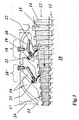
- the axial compressor 10 has a central rotor 11 which carries a multiplicity of rotor blades 14 which are radially oriented and project into an annular gas passage 12 which tapers in cross section.
- the rotor blades 14 alternate in the gas passage 12 with stator blades 15 which are attached on the inner side of a casing 13 which concentrically encloses the rotor 11.
- the positioning of the rotor blades 14 is selected so that during corresponding rotation of the rotor 11 the gas in the gas passage 12, coming from the right in the direction of the drawn-in arrow, flows to the left and is compressed in the process.
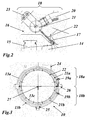
- a plurality of encompassing bleed air chambers 16, adjoining the gas passage 12 on the outside, are formed in the casing 13 of the axial compressor 10 and are in communication with the gas passage 12 via encompassing bleed air slots 17 which are inclined in the flow direction. Via the bleed air slots 17, compressed air flows into the adjoining bleed air chambers 16 during operation and from there, via bleed air flanges 24 (and 25 in Fig. 3 ) which are arranged on the outside on the axial compressor 10, is discharged for further utilization.
- the bleed air chambers 16 constitute suitable spaces in order to accommodate, at little cost, the injection devices 18 or 18' which are required for injecting a fluid.
- the associated bleed air slots 17, from their design and inclination, are particularly well suited to accommodating the associated nozzles 22.
- pipe bends 21 or 21 a, b are fastened in each case on an inner wall of the bleed air chambers 16 by means of suitable support elements 23, from which pipe bends the nozzles 22, distributed over the circumference, project into the associated bleed air slots 17 to such an extent that the tips of the nozzles 22 end on the outer edge of the gas passage 12 or on the casing inner wall (13c in Fig. 3 ) (see Fig. 2 ).
- the pipe bends 21 or 21 a, b are connected via flexible connecting hoses 20 to corresponding connecting flanges 19 or 19a, b which project from the outside through the outer casing wall into the bleed air chambers 16.
- the outer compressor casing is mechanically machined in order to attach the connecting flanges 19 or 19a, b. Furthermore, the casing is machined in the parting plane in order to attach the support elements 23 for the pipe bends 21 or 21 a, b. Finally, the semi-circular pipe bends 21 a, b can be installed with the nozzles 22 arranged thereupon.
- the injection devices therefore comprise two semi-circular pipe bends in a concentric bleed air chamber with a multiplicity of nozzles which are arranged along the pipe axis.
- the nozzles are directed into the associated bleed air slot which is normally positioned directly after a stator blade row and in front of a rotor blade row in the flow direction (see the injection devices 18, 18' in Fig. 1 ).
- Each of the pipe bends is connected by means of a flexible connecting hose to a corresponding connecting flange passing through the casing, through which pipe bend the fluid is introduced.
- the nozzles create a fine spray mist in the shape of a cone which is oriented against the flow direction and covers the entire height of the gas passage (see Fig. 1 ).
Landscapes
- Engineering & Computer Science (AREA)
- Mechanical Engineering (AREA)
- General Engineering & Computer Science (AREA)
- Chemical & Material Sciences (AREA)
- Combustion & Propulsion (AREA)
- Physics & Mathematics (AREA)
- Life Sciences & Earth Sciences (AREA)
- Sustainable Development (AREA)
- Fluid Mechanics (AREA)
- Thermal Sciences (AREA)
- Structures Of Non-Positive Displacement Pumps (AREA)
Claims (12)
- Axialverdichter (10) zum Verdichten von Luft, insbesondere für eine Gasturbine, welcher Axialverdichter (10) einen Rotor (11), der um eine Maschinenachse (27) drehbar ist und eine Vielzahl von Rotorblättern (14) hat, sowie ein Gehäuse (13, 13a, b) aufweist, das den Rotor (11) konzentrisch und in einem Abstand umgibt, welches Gehäuse (13, 13a, b) zusammen mit dem Rotor (11) einen ringförmigen Gaskanal (12) bildet und außerhalb des Gaskanals (12) mindestens eine im Wesentlichen ringförmige und konzentrische Nebenluftkammer (16) hat, wobei die Nebenluftkammer mindestens einen Nebenluftschlitz (17) aufweist, wobei der Schlitz in Funktionsverbindung mit dem Gaskanal (12) steht, wobei der Axialverdichter (10) mit mindestens einer Einspritzeinrichtung (18; 18', 18a, b) zum Einspritzen eines Fluids ausgestattet ist, welche mindestens eine Düse (22) aufweist, dadurch gekennzeichnet, dass die mindestens eine Düse (22) dafür konfiguriert ist, das Fluid über den Nebenluftschlitz (17) in den Gaskanal (12) zu einzuspritzen.
- Axialverdichter nach Anspruch 1, dadurch gekennzeichnet, dass der Nebenluftschlitz (17) eine ringförmige und konzentrische Konstruktion aufweist, dass die Einspritzeinrichtung eine Anzahl von Düsen (22) hat, die über den Umfang des Nebenluftschlitzes (17) verteilt sind, um das Fluid in den Gaskanal (12) zuzuliefern und zu verteilen.
- Axialverdichter nach Anspruch 1 oder 2, dadurch gekennzeichnet, dass mindestens eine Einspritzeinrichtung (18; 18', 18a, b) eine erste Einrichtung (20, 21, 21 a, b) zum Zuliefern und Verteilen des Fluids zu der Düse (22) aufweist, welche in der Nebenluftkammer (16) in Verbindung mit dem Nebenluftschlitz (17) angeordnet ist, und dass die erste Einrichtung (20, 21, 21a, b) einen Verbindungsflansch (19, 19a, b) hat, der an dem Gehäuse (13, 13a, b) befestigt ist, welcher die Einspritzeinrichtung von außerhalb mit dem Fluid versorgt.
- Axialverdichter nach einem der Ansprüche 1 bis 3, dadurch gekennzeichnet, dass die Düsen (22) in dem Nebenluftschlitz (17) angeordnet sind.
- Axialverdichter nach einem der Ansprüche 1 bis 4, dadurch gekennzeichnet, dass die Düsen (22) mit ihrer Düsenachse in Richtung der Maschinenachse (27) ausgerichtet sind und in der Strömungsrichtung dergestalt in einer aus der radialen Richtung gekippten Weise angeordnet sind, dass das Fluid gegen den Strom in dem Gaskanal (12) eingespritzt wird.
- Axialverdichter nach einem der Ansprüche 1 bis 5, dadurch gekennzeichnet, dass die erste Einrichtung (20, 21, 21a, b) einen Rohrbogen (21, 21a, b) umfasst, der quer zu der Strömungsrichtung durch die Nebenluftkammer (16) verläuft und an welchem die Düsen (22) befestigt sind.
- Axialverdichter nach Anspruch 6, dadurch gekennzeichnet, dass der Rohrbogen (21, 21a, b) an einer Innenwand der Nebenluftkammer (16) befestigt ist, und dass der Rohrbogen (21, 21a, b) mit dem Verbindungsflansch (19, 19a, b) über einen flexiblen Verbindungsschlauch (20) verbunden ist.
- Axialverdichter nach einem der Ansprüche 1 bis 7, dadurch gekennzeichnet, dass das Gehäuse (13) in einer horizontalen Teilungsebene in eine obere Gehäusehälfte (13a) und eine untere Gehäusehälfte (13b) geteilt ist, dass die Einspritzeinrichtung (18; 18', 18a, b) dem Gehäuse (13) entsprechend in eine obere Einspritzeinrichtung (18a) und eine untere Einspritzeinrichtung (18b) geteilt ist und dass ein separater Verbindungflansch (19a oder 19b) in jedem Fall der oberen Einspritzeinrichtung (18a) und der unteren Einspritzeinrichtung (18b) zugehörig ist.
- Axialverdichter nach Anspruch 8, dadurch gekennzeichnet, dass die erste Einrichtung (20, 21, 21a, b) in jedem Fall einen halbkreisförmigen Rohrbogen (21a, b) für die obere Einspritzeinrichtung (18a) und für die untere Einspritzeinrichtung (18b) aufweist, der quer zur Strömungsrichtung durch die Nebenluftkammer (16) verläuft und an welchem die Düsen (22) befestigt sind.
- Axialverdichter nach einem der Ansprüche 1 bis 9, dadurch gekennzeichnet, dass eine Vielzahl von Einspritzeinrichtungen (18, 18') derselben Bauart in Reihe in der Axialrichtung angeordnet sind.
- Verfahren zur Herstellung eines Axialverdichters nach den Ansprüchen 8 oder 9, enthaltend die folgenden Schritte:- Bereitstellen eines Gehäuses (13), welches an einer horizontalen Trennlinie in eine obere Gehäusehälfte (13a) und eine untere Gehäusehälfte (13b) geteilt ist;- Anbringen von Verbindungsflanschen (19a, 19b) an dem Gehäuse in einem ersten Schritt;- Anbringen von Halteelement (23) für die erste Einrichtung (20, 21, 21a, b) an einer Innenwand der Nebenluftkammer (16) in einem weiteren Schritt; und- Befestigen der ersten Einrichtung (20, 21, 21a, b) mit den fest daran angeordneten Düsen (22) an den Halteelementen (23) in einem weiteren Schritt.
- Gasturbine mit einem Axialverdichter nach einem der Ansprüche 1 bis 10.
Applications Claiming Priority (1)
| Application Number | Priority Date | Filing Date | Title |
|---|---|---|---|
| CH01237/11A CH705324A1 (de) | 2011-07-25 | 2011-07-25 | Axialverdichter mit einer Einspritzvorrichtung zum Eindüsen einer Flüssigkeit. |
Publications (2)
| Publication Number | Publication Date |
|---|---|
| EP2551490A1 EP2551490A1 (de) | 2013-01-30 |
| EP2551490B1 true EP2551490B1 (de) | 2016-10-26 |
Family
ID=46397105
Family Applications (1)
| Application Number | Title | Priority Date | Filing Date |
|---|---|---|---|
| EP12175327.1A Not-in-force EP2551490B1 (de) | 2011-07-25 | 2012-07-06 | Axialkompressor mit einer Einspritzvorrichtung zum Einspritzen einer Flüssigkeit |
Country Status (4)
| Country | Link |
|---|---|
| US (1) | US9004853B2 (de) |
| EP (1) | EP2551490B1 (de) |
| JP (1) | JP5661692B2 (de) |
| CH (1) | CH705324A1 (de) |
Families Citing this family (9)
| Publication number | Priority date | Publication date | Assignee | Title |
|---|---|---|---|---|
| US9376933B2 (en) * | 2011-04-29 | 2016-06-28 | Leonard M. Andersen | Apparatus for distributing fluid into a gas turbine |
| EP2987966A1 (de) * | 2014-08-21 | 2016-02-24 | Siemens Aktiengesellschaft | Gasturbine mit in Ringsektoren unterteiltem Kühlringkanal |
| US20160169107A1 (en) * | 2014-12-12 | 2016-06-16 | General Electric Company | Systems and methods for injecting fluids at one or more stages of a multi-stage component |
| US9951647B2 (en) * | 2015-12-17 | 2018-04-24 | General Electric Company | System and method for in situ cleaning of internal components of a gas turbine engine and a related plug assembly |
| US11022037B2 (en) | 2018-01-04 | 2021-06-01 | General Electric Company | Gas turbine engine thermal management system |
| US10941706B2 (en) | 2018-02-13 | 2021-03-09 | General Electric Company | Closed cycle heat engine for a gas turbine engine |
| US11143104B2 (en) | 2018-02-20 | 2021-10-12 | General Electric Company | Thermal management system |
| US11015534B2 (en) | 2018-11-28 | 2021-05-25 | General Electric Company | Thermal management system |
| US12612874B2 (en) * | 2024-01-18 | 2026-04-28 | General Electric Company | Power system having a gas turbine engine |
Family Cites Families (11)
| Publication number | Priority date | Publication date | Assignee | Title |
|---|---|---|---|---|
| GB685944A (en) * | 1949-09-30 | 1953-01-14 | Rateau Soc | Improvements in jet propulsion engines |
| US4711084A (en) * | 1981-11-05 | 1987-12-08 | Avco Corporation | Ejector assisted compressor bleed |
| US5351478A (en) * | 1992-05-29 | 1994-10-04 | General Electric Company | Compressor casing assembly |
| DE4446543A1 (de) * | 1994-12-24 | 1996-06-27 | Abb Management Ag | Kraftwerksanlage |
| DE19839592A1 (de) | 1998-08-31 | 2000-03-02 | Asea Brown Boveri | Strömungsmaschine mit gekühlter Rotorwelle |
| US6126389A (en) * | 1998-09-02 | 2000-10-03 | General Electric Co. | Impingement cooling for the shroud of a gas turbine |
| US6398518B1 (en) * | 2000-03-29 | 2002-06-04 | Watson Cogeneration Company | Method and apparatus for increasing the efficiency of a multi-stage compressor |
| US20050141991A1 (en) * | 2001-10-17 | 2005-06-30 | Frutschi Hans U. | Method for conditioning a compressor airflow and device therefor |
| US6935119B2 (en) * | 2003-03-14 | 2005-08-30 | General Electric Company | Methods for operating gas turbine engines |
| US7033135B2 (en) | 2003-11-10 | 2006-04-25 | General Electric Company | Method and apparatus for distributing fluid into a turbomachine |
| DE102008025511A1 (de) * | 2008-05-28 | 2009-12-03 | Mtu Aero Engines Gmbh | Gehäuse für einen Verdichter einer Gasturbine, Verdichter und Verfahren zur Herstellung eines Gehäusesegments eines Verdichtergehäuses |
-
2011
- 2011-07-25 CH CH01237/11A patent/CH705324A1/de not_active Application Discontinuation
-
2012
- 2012-07-06 EP EP12175327.1A patent/EP2551490B1/de not_active Not-in-force
- 2012-07-24 US US13/556,788 patent/US9004853B2/en active Active
- 2012-07-25 JP JP2012164657A patent/JP5661692B2/ja not_active Expired - Fee Related
Also Published As
| Publication number | Publication date |
|---|---|
| US20130058760A1 (en) | 2013-03-07 |
| JP5661692B2 (ja) | 2015-01-28 |
| JP2013024248A (ja) | 2013-02-04 |
| CH705324A1 (de) | 2013-01-31 |
| EP2551490A1 (de) | 2013-01-30 |
| US9004853B2 (en) | 2015-04-14 |
Similar Documents
| Publication | Publication Date | Title |
|---|---|---|
| EP2551490A1 (de) | Axialkompressor mit einer Einspritzvorrichtung zum Einspritzen einer Flüssigkeit | |
| CN102119268B (zh) | 燃气轮机中使用的具有带排气口的线性流动路径的过渡件 | |
| US9759092B2 (en) | Casing cooling duct | |
| JP5507828B2 (ja) | 非対称流れ抽出システム | |
| US8092152B2 (en) | Device for cooling slots of a turbomachine rotor disk | |
| CN107975424B (zh) | 轴向涡轮机压缩机的除冰鼻部 | |
| EP3306197B1 (de) | Zweikraftstoffinjektor für einen brenner der zweiten stufe einer sequentiellen gasturbine | |
| WO2010019175A2 (en) | Transition with a linear flow path for use in a gas turbine engine | |
| US20160069209A1 (en) | Device for washing a turbomachine air intake casing | |
| US11585228B2 (en) | Technique for cooling inner shroud of a gas turbine vane | |
| US9903382B2 (en) | Axial compressor for fluid-flow machines | |
| EP3159486A1 (de) | Radraumdurchflussmischkammer | |
| CN103987942A (zh) | 用于代替燃气轮机的燃烧器组件的方法及相应的燃气轮机 | |
| US8087871B2 (en) | Turbomachine compressor wheel member | |
| US10393019B2 (en) | Assembly and method for influencing flow through a fan of a gas turbine engine | |
| EP3265653B1 (de) | Turbine für organische rankine-kreisläufe mit axialem eingang und ausgang | |
| US20160177835A1 (en) | Gas turbine engine with angularly offset turbine vanes | |
| US9587509B2 (en) | Assembly for a fluid flow machine | |
| KR20190046118A (ko) | 터빈 블레이드 | |
| US10132195B2 (en) | Wheel space purge flow mixing chamber | |
| EP4174286B1 (de) | Gasturbinenanordnung für ein kraftwerk mit verbesserter rotor- und turbinenschaufelkühlung und verfahren zum betrieb dieser gasturbinenanordnung | |
| JP7155400B2 (ja) | ガスタービンエンジンの冷却流体用のモジュラケーシングマニホールド | |
| US20210388762A1 (en) | Device for de-icing a turbomachine nozzle | |
| US20240271529A1 (en) | Radial turbine impeller | |
| JP7368274B2 (ja) | ガスタービン用燃料噴射装置 |
Legal Events
| Date | Code | Title | Description |
|---|---|---|---|
| PUAI | Public reference made under article 153(3) epc to a published international application that has entered the european phase |
Free format text: ORIGINAL CODE: 0009012 |
|
| AK | Designated contracting states |
Kind code of ref document: A1 Designated state(s): AL AT BE BG CH CY CZ DE DK EE ES FI FR GB GR HR HU IE IS IT LI LT LU LV MC MK MT NL NO PL PT RO RS SE SI SK SM TR |
|
| AX | Request for extension of the european patent |
Extension state: BA ME |
|
| 17P | Request for examination filed |
Effective date: 20130717 |
|
| RBV | Designated contracting states (corrected) |
Designated state(s): AL AT BE BG CH CY CZ DE DK EE ES FI FR GB GR HR HU IE IS IT LI LT LU LV MC MK MT NL NO PL PT RO RS SE SI SK SM TR |
|
| GRAP | Despatch of communication of intention to grant a patent |
Free format text: ORIGINAL CODE: EPIDOSNIGR1 |
|
| INTG | Intention to grant announced |
Effective date: 20160512 |
|
| RAP1 | Party data changed (applicant data changed or rights of an application transferred) |
Owner name: GENERAL ELECTRIC TECHNOLOGY GMBH |
|
| GRAS | Grant fee paid |
Free format text: ORIGINAL CODE: EPIDOSNIGR3 |
|
| GRAA | (expected) grant |
Free format text: ORIGINAL CODE: 0009210 |
|
| AK | Designated contracting states |
Kind code of ref document: B1 Designated state(s): AL AT BE BG CH CY CZ DE DK EE ES FI FR GB GR HR HU IE IS IT LI LT LU LV MC MK MT NL NO PL PT RO RS SE SI SK SM TR |
|
| REG | Reference to a national code |
Ref country code: GB Ref legal event code: FG4D |
|
| REG | Reference to a national code |
Ref country code: CH Ref legal event code: EP |
|
| REG | Reference to a national code |
Ref country code: AT Ref legal event code: REF Ref document number: 840206 Country of ref document: AT Kind code of ref document: T Effective date: 20161115 |
|
| REG | Reference to a national code |
Ref country code: IE Ref legal event code: FG4D |
|
| REG | Reference to a national code |
Ref country code: DE Ref legal event code: R096 Ref document number: 602012024522 Country of ref document: DE |
|
| REG | Reference to a national code |
Ref country code: LT Ref legal event code: MG4D |
|
| PG25 | Lapsed in a contracting state [announced via postgrant information from national office to epo] |
Ref country code: LV Free format text: LAPSE BECAUSE OF FAILURE TO SUBMIT A TRANSLATION OF THE DESCRIPTION OR TO PAY THE FEE WITHIN THE PRESCRIBED TIME-LIMIT Effective date: 20161026 |
|
| REG | Reference to a national code |
Ref country code: NL Ref legal event code: MP Effective date: 20161026 |
|
| REG | Reference to a national code |
Ref country code: AT Ref legal event code: MK05 Ref document number: 840206 Country of ref document: AT Kind code of ref document: T Effective date: 20161026 |
|
| PG25 | Lapsed in a contracting state [announced via postgrant information from national office to epo] |
Ref country code: SE Free format text: LAPSE BECAUSE OF FAILURE TO SUBMIT A TRANSLATION OF THE DESCRIPTION OR TO PAY THE FEE WITHIN THE PRESCRIBED TIME-LIMIT Effective date: 20161026 Ref country code: GR Free format text: LAPSE BECAUSE OF FAILURE TO SUBMIT A TRANSLATION OF THE DESCRIPTION OR TO PAY THE FEE WITHIN THE PRESCRIBED TIME-LIMIT Effective date: 20170127 Ref country code: LT Free format text: LAPSE BECAUSE OF FAILURE TO SUBMIT A TRANSLATION OF THE DESCRIPTION OR TO PAY THE FEE WITHIN THE PRESCRIBED TIME-LIMIT Effective date: 20161026 Ref country code: NO Free format text: LAPSE BECAUSE OF FAILURE TO SUBMIT A TRANSLATION OF THE DESCRIPTION OR TO PAY THE FEE WITHIN THE PRESCRIBED TIME-LIMIT Effective date: 20170126 |
|
| PG25 | Lapsed in a contracting state [announced via postgrant information from national office to epo] |
Ref country code: FI Free format text: LAPSE BECAUSE OF FAILURE TO SUBMIT A TRANSLATION OF THE DESCRIPTION OR TO PAY THE FEE WITHIN THE PRESCRIBED TIME-LIMIT Effective date: 20161026 Ref country code: BE Free format text: LAPSE BECAUSE OF FAILURE TO SUBMIT A TRANSLATION OF THE DESCRIPTION OR TO PAY THE FEE WITHIN THE PRESCRIBED TIME-LIMIT Effective date: 20161026 Ref country code: NL Free format text: LAPSE BECAUSE OF FAILURE TO SUBMIT A TRANSLATION OF THE DESCRIPTION OR TO PAY THE FEE WITHIN THE PRESCRIBED TIME-LIMIT Effective date: 20161026 Ref country code: PL Free format text: LAPSE BECAUSE OF FAILURE TO SUBMIT A TRANSLATION OF THE DESCRIPTION OR TO PAY THE FEE WITHIN THE PRESCRIBED TIME-LIMIT Effective date: 20161026 Ref country code: PT Free format text: LAPSE BECAUSE OF FAILURE TO SUBMIT A TRANSLATION OF THE DESCRIPTION OR TO PAY THE FEE WITHIN THE PRESCRIBED TIME-LIMIT Effective date: 20170227 Ref country code: ES Free format text: LAPSE BECAUSE OF FAILURE TO SUBMIT A TRANSLATION OF THE DESCRIPTION OR TO PAY THE FEE WITHIN THE PRESCRIBED TIME-LIMIT Effective date: 20161026 Ref country code: HR Free format text: LAPSE BECAUSE OF FAILURE TO SUBMIT A TRANSLATION OF THE DESCRIPTION OR TO PAY THE FEE WITHIN THE PRESCRIBED TIME-LIMIT Effective date: 20161026 Ref country code: RS Free format text: LAPSE BECAUSE OF FAILURE TO SUBMIT A TRANSLATION OF THE DESCRIPTION OR TO PAY THE FEE WITHIN THE PRESCRIBED TIME-LIMIT Effective date: 20161026 Ref country code: IS Free format text: LAPSE BECAUSE OF FAILURE TO SUBMIT A TRANSLATION OF THE DESCRIPTION OR TO PAY THE FEE WITHIN THE PRESCRIBED TIME-LIMIT Effective date: 20170226 Ref country code: AT Free format text: LAPSE BECAUSE OF FAILURE TO SUBMIT A TRANSLATION OF THE DESCRIPTION OR TO PAY THE FEE WITHIN THE PRESCRIBED TIME-LIMIT Effective date: 20161026 |
|
| RAP2 | Party data changed (patent owner data changed or rights of a patent transferred) |
Owner name: ANSALDO ENERGIA SWITZERLAND AG |
|
| REG | Reference to a national code |
Ref country code: DE Ref legal event code: R097 Ref document number: 602012024522 Country of ref document: DE |
|
| PG25 | Lapsed in a contracting state [announced via postgrant information from national office to epo] |
Ref country code: RO Free format text: LAPSE BECAUSE OF FAILURE TO SUBMIT A TRANSLATION OF THE DESCRIPTION OR TO PAY THE FEE WITHIN THE PRESCRIBED TIME-LIMIT Effective date: 20161026 Ref country code: EE Free format text: LAPSE BECAUSE OF FAILURE TO SUBMIT A TRANSLATION OF THE DESCRIPTION OR TO PAY THE FEE WITHIN THE PRESCRIBED TIME-LIMIT Effective date: 20161026 Ref country code: DK Free format text: LAPSE BECAUSE OF FAILURE TO SUBMIT A TRANSLATION OF THE DESCRIPTION OR TO PAY THE FEE WITHIN THE PRESCRIBED TIME-LIMIT Effective date: 20161026 Ref country code: CZ Free format text: LAPSE BECAUSE OF FAILURE TO SUBMIT A TRANSLATION OF THE DESCRIPTION OR TO PAY THE FEE WITHIN THE PRESCRIBED TIME-LIMIT Effective date: 20161026 Ref country code: SK Free format text: LAPSE BECAUSE OF FAILURE TO SUBMIT A TRANSLATION OF THE DESCRIPTION OR TO PAY THE FEE WITHIN THE PRESCRIBED TIME-LIMIT Effective date: 20161026 |
|
| PG25 | Lapsed in a contracting state [announced via postgrant information from national office to epo] |
Ref country code: BG Free format text: LAPSE BECAUSE OF FAILURE TO SUBMIT A TRANSLATION OF THE DESCRIPTION OR TO PAY THE FEE WITHIN THE PRESCRIBED TIME-LIMIT Effective date: 20170126 Ref country code: SM Free format text: LAPSE BECAUSE OF FAILURE TO SUBMIT A TRANSLATION OF THE DESCRIPTION OR TO PAY THE FEE WITHIN THE PRESCRIBED TIME-LIMIT Effective date: 20161026 |
|
| PLBE | No opposition filed within time limit |
Free format text: ORIGINAL CODE: 0009261 |
|
| STAA | Information on the status of an ep patent application or granted ep patent |
Free format text: STATUS: NO OPPOSITION FILED WITHIN TIME LIMIT |
|
| 26N | No opposition filed |
Effective date: 20170727 |
|
| PGFP | Annual fee paid to national office [announced via postgrant information from national office to epo] |
Ref country code: GB Payment date: 20170719 Year of fee payment: 6 Ref country code: DE Payment date: 20170724 Year of fee payment: 6 Ref country code: IT Payment date: 20170728 Year of fee payment: 6 |
|
| PG25 | Lapsed in a contracting state [announced via postgrant information from national office to epo] |
Ref country code: SI Free format text: LAPSE BECAUSE OF FAILURE TO SUBMIT A TRANSLATION OF THE DESCRIPTION OR TO PAY THE FEE WITHIN THE PRESCRIBED TIME-LIMIT Effective date: 20161026 |
|
| REG | Reference to a national code |
Ref country code: CH Ref legal event code: PL |
|
| REG | Reference to a national code |
Ref country code: IE Ref legal event code: MM4A |
|
| REG | Reference to a national code |
Ref country code: FR Ref legal event code: ST Effective date: 20180330 |
|
| PG25 | Lapsed in a contracting state [announced via postgrant information from national office to epo] |
Ref country code: CH Free format text: LAPSE BECAUSE OF NON-PAYMENT OF DUE FEES Effective date: 20170731 Ref country code: LI Free format text: LAPSE BECAUSE OF NON-PAYMENT OF DUE FEES Effective date: 20170731 Ref country code: IE Free format text: LAPSE BECAUSE OF NON-PAYMENT OF DUE FEES Effective date: 20170706 |
|
| PG25 | Lapsed in a contracting state [announced via postgrant information from national office to epo] |
Ref country code: FR Free format text: LAPSE BECAUSE OF NON-PAYMENT OF DUE FEES Effective date: 20170731 |
|
| PG25 | Lapsed in a contracting state [announced via postgrant information from national office to epo] |
Ref country code: LU Free format text: LAPSE BECAUSE OF NON-PAYMENT OF DUE FEES Effective date: 20170706 |
|
| PG25 | Lapsed in a contracting state [announced via postgrant information from national office to epo] |
Ref country code: MT Free format text: LAPSE BECAUSE OF NON-PAYMENT OF DUE FEES Effective date: 20170706 |
|
| REG | Reference to a national code |
Ref country code: DE Ref legal event code: R119 Ref document number: 602012024522 Country of ref document: DE |
|
| GBPC | Gb: european patent ceased through non-payment of renewal fee |
Effective date: 20180706 |
|
| PG25 | Lapsed in a contracting state [announced via postgrant information from national office to epo] |
Ref country code: DE Free format text: LAPSE BECAUSE OF NON-PAYMENT OF DUE FEES Effective date: 20190201 Ref country code: GB Free format text: LAPSE BECAUSE OF NON-PAYMENT OF DUE FEES Effective date: 20180706 |
|
| PG25 | Lapsed in a contracting state [announced via postgrant information from national office to epo] |
Ref country code: MC Free format text: LAPSE BECAUSE OF FAILURE TO SUBMIT A TRANSLATION OF THE DESCRIPTION OR TO PAY THE FEE WITHIN THE PRESCRIBED TIME-LIMIT Effective date: 20161026 Ref country code: HU Free format text: LAPSE BECAUSE OF FAILURE TO SUBMIT A TRANSLATION OF THE DESCRIPTION OR TO PAY THE FEE WITHIN THE PRESCRIBED TIME-LIMIT; INVALID AB INITIO Effective date: 20120706 |
|
| PG25 | Lapsed in a contracting state [announced via postgrant information from national office to epo] |
Ref country code: IT Free format text: LAPSE BECAUSE OF NON-PAYMENT OF DUE FEES Effective date: 20180706 |
|
| PG25 | Lapsed in a contracting state [announced via postgrant information from national office to epo] |
Ref country code: CY Free format text: LAPSE BECAUSE OF NON-PAYMENT OF DUE FEES Effective date: 20161026 |
|
| PG25 | Lapsed in a contracting state [announced via postgrant information from national office to epo] |
Ref country code: MK Free format text: LAPSE BECAUSE OF FAILURE TO SUBMIT A TRANSLATION OF THE DESCRIPTION OR TO PAY THE FEE WITHIN THE PRESCRIBED TIME-LIMIT Effective date: 20161026 |
|
| PG25 | Lapsed in a contracting state [announced via postgrant information from national office to epo] |
Ref country code: TR Free format text: LAPSE BECAUSE OF FAILURE TO SUBMIT A TRANSLATION OF THE DESCRIPTION OR TO PAY THE FEE WITHIN THE PRESCRIBED TIME-LIMIT Effective date: 20161026 |
|
| PG25 | Lapsed in a contracting state [announced via postgrant information from national office to epo] |
Ref country code: AL Free format text: LAPSE BECAUSE OF FAILURE TO SUBMIT A TRANSLATION OF THE DESCRIPTION OR TO PAY THE FEE WITHIN THE PRESCRIBED TIME-LIMIT Effective date: 20161026 |