EP2551482A1 - Ensemble coude de post-traitement des gaz d'echappement d'un moteur à combustion comportant un convergent interne - Google Patents
Ensemble coude de post-traitement des gaz d'echappement d'un moteur à combustion comportant un convergent interne Download PDFInfo
- Publication number
- EP2551482A1 EP2551482A1 EP12172131A EP12172131A EP2551482A1 EP 2551482 A1 EP2551482 A1 EP 2551482A1 EP 12172131 A EP12172131 A EP 12172131A EP 12172131 A EP12172131 A EP 12172131A EP 2551482 A1 EP2551482 A1 EP 2551482A1
- Authority
- EP
- European Patent Office
- Prior art keywords
- convergent
- assembly
- scr
- casing
- oxidation catalyst
- Prior art date
- Legal status (The legal status is an assumption and is not a legal conclusion. Google has not performed a legal analysis and makes no representation as to the accuracy of the status listed.)
- Granted
Links
Images

Classifications
-
- F—MECHANICAL ENGINEERING; LIGHTING; HEATING; WEAPONS; BLASTING
- F01—MACHINES OR ENGINES IN GENERAL; ENGINE PLANTS IN GENERAL; STEAM ENGINES
- F01N—GAS-FLOW SILENCERS OR EXHAUST APPARATUS FOR MACHINES OR ENGINES IN GENERAL; GAS-FLOW SILENCERS OR EXHAUST APPARATUS FOR INTERNAL-COMBUSTION ENGINES
- F01N3/00—Exhaust or silencing apparatus having means for purifying, rendering innocuous, or otherwise treating exhaust
- F01N3/08—Exhaust or silencing apparatus having means for purifying, rendering innocuous, or otherwise treating exhaust for rendering innocuous
- F01N3/10—Exhaust or silencing apparatus having means for purifying, rendering innocuous, or otherwise treating exhaust for rendering innocuous by thermal or catalytic conversion of noxious components of exhaust
- F01N3/18—Exhaust or silencing apparatus having means for purifying, rendering innocuous, or otherwise treating exhaust for rendering innocuous by thermal or catalytic conversion of noxious components of exhaust characterised by methods of operation; Control
- F01N3/20—Exhaust or silencing apparatus having means for purifying, rendering innocuous, or otherwise treating exhaust for rendering innocuous by thermal or catalytic conversion of noxious components of exhaust characterised by methods of operation; Control specially adapted for catalytic conversion
- F01N3/206—Adding periodically or continuously substances to exhaust gases for promoting purification, e.g. catalytic material in liquid form, NOx reducing agents
- F01N3/2066—Selective catalytic reduction [SCR]
-
- F—MECHANICAL ENGINEERING; LIGHTING; HEATING; WEAPONS; BLASTING
- F01—MACHINES OR ENGINES IN GENERAL; ENGINE PLANTS IN GENERAL; STEAM ENGINES
- F01N—GAS-FLOW SILENCERS OR EXHAUST APPARATUS FOR MACHINES OR ENGINES IN GENERAL; GAS-FLOW SILENCERS OR EXHAUST APPARATUS FOR INTERNAL-COMBUSTION ENGINES
- F01N3/00—Exhaust or silencing apparatus having means for purifying, rendering innocuous, or otherwise treating exhaust
- F01N3/08—Exhaust or silencing apparatus having means for purifying, rendering innocuous, or otherwise treating exhaust for rendering innocuous
- F01N3/10—Exhaust or silencing apparatus having means for purifying, rendering innocuous, or otherwise treating exhaust for rendering innocuous by thermal or catalytic conversion of noxious components of exhaust
- F01N3/105—General auxiliary catalysts, e.g. upstream or downstream of the main catalyst
- F01N3/106—Auxiliary oxidation catalysts
-
- F—MECHANICAL ENGINEERING; LIGHTING; HEATING; WEAPONS; BLASTING
- F01—MACHINES OR ENGINES IN GENERAL; ENGINE PLANTS IN GENERAL; STEAM ENGINES
- F01N—GAS-FLOW SILENCERS OR EXHAUST APPARATUS FOR MACHINES OR ENGINES IN GENERAL; GAS-FLOW SILENCERS OR EXHAUST APPARATUS FOR INTERNAL-COMBUSTION ENGINES
- F01N2240/00—Combination or association of two or more different exhaust treating devices, or of at least one such device with an auxiliary device, not covered by indexing codes F01N2230/00 or F01N2250/00, one of the devices being
- F01N2240/20—Combination or association of two or more different exhaust treating devices, or of at least one such device with an auxiliary device, not covered by indexing codes F01N2230/00 or F01N2250/00, one of the devices being a flow director or deflector
-
- F—MECHANICAL ENGINEERING; LIGHTING; HEATING; WEAPONS; BLASTING
- F01—MACHINES OR ENGINES IN GENERAL; ENGINE PLANTS IN GENERAL; STEAM ENGINES
- F01N—GAS-FLOW SILENCERS OR EXHAUST APPARATUS FOR MACHINES OR ENGINES IN GENERAL; GAS-FLOW SILENCERS OR EXHAUST APPARATUS FOR INTERNAL-COMBUSTION ENGINES
- F01N2610/00—Adding substances to exhaust gases
- F01N2610/02—Adding substances to exhaust gases the substance being ammonia or urea
-
- Y—GENERAL TAGGING OF NEW TECHNOLOGICAL DEVELOPMENTS; GENERAL TAGGING OF CROSS-SECTIONAL TECHNOLOGIES SPANNING OVER SEVERAL SECTIONS OF THE IPC; TECHNICAL SUBJECTS COVERED BY FORMER USPC CROSS-REFERENCE ART COLLECTIONS [XRACs] AND DIGESTS
- Y02—TECHNOLOGIES OR APPLICATIONS FOR MITIGATION OR ADAPTATION AGAINST CLIMATE CHANGE
- Y02T—CLIMATE CHANGE MITIGATION TECHNOLOGIES RELATED TO TRANSPORTATION
- Y02T10/00—Road transport of goods or passengers
- Y02T10/10—Internal combustion engine [ICE] based vehicles
- Y02T10/12—Improving ICE efficiencies
Definitions
- the invention relates to the field of means for cleaning up the exhaust gases of a combustion engine.
- the polluting emissions of combustion engines fitted to motor vehicles are regulated by ever more stringent standards.
- Regulated pollutants are carbon monoxide (CO), unburned hydrocarbons (HC), nitrogen oxides (NOx), and particulates, depending on the combustion engine technology.
- An oxidation catalyst allows the treatment of carbon monoxide, unburned hydrocarbons, and under certain conditions nitrogen oxides; a particulate filter can be used for the treatment of soot particles.
- after-treatment means of the exhaust gases.
- a specific aftertreatment system can be introduced into the exhaust line of vehicles, including vehicles equipped with mixing engines. poor, that is to say of the diesel or spark ignition type operating with a stratified mixture (non-homogeneous fuel mixture having a fuel content lower than the stoichiometry).
- SCR selective catalytic reduction
- a reducing agent or a precursor of such a reducing agent
- It may for example be a urea solution, the decomposition of which will make it possible to obtain ammonia which will serve as a reducing agent, but also of a reducing agent or a precursor of such a reducing agent. gaseous form.
- a "reducing agent” will generally be used to designate a reducing agent or a reducing agent precursor.
- SCR catalyst should therefore be interpreted as referring to a catalyst specifically dedicated to the selective catalytic reduction function of nitrogen oxides, or a particulate filter carrying a catalytic impregnation. selective catalytic reduction of nitrogen oxides.
- the SCR catalyst is placed under the body of the equipped vehicle, away from the engine because the injected reducer requires a long run in the exhaust line to decompose on the one hand, and free volumes sufficient to be implanted other go. If the distance traveled by the reducer is not sufficient the risk of clogging of the exhaust line is important.
- the SCR catalyst may not be active from the first seconds of operation of the engine. vehicle, and then let pass a large amount of untreated nitrogen oxides.
- the gearbox injector which requires reaching a certain temperature level to be operational (sufficient initiation of decomposition of the urea precursor in liquid form or preheating of the gaseous reducer delivery system), suffers this distance from the outlet of the exhaust manifold.
- mixer interposed between the reducer injection point and the SCR catalyst, which aims to create turbulence in the exhaust gas.
- mixers suitable for this purpose.
- the mixers are optimized to reduce as much as possible the length of the exhaust line necessary to obtain a good homogeneity of the mixture reducer / exhaust gas.
- Mixers are, however, often complex devices, and adapted to an exhaust line in which the different depollution devices are arranged one after the other, in a conventional longitudinal arrangement.
- Most known mixers are cylindrical and must be arranged in a cylindrical envelope or "canning".
- the object of the invention is to propose means for ensuring a homogeneous mixture of a fluid introduced into the exhaust gas of a combustion engine, as part of an architecture of a post-treatment device.
- compact exhaust having a single and bent envelope (canning), for example "U” or "L”, taking advantage of this configuration to ensure the mixing function efficiently, simply, and at a cost reduced.
- the inlet of the convergent covers the entire section of the envelope so that all of a gas stream flowing in the assembly enters the convergent.
- the convergent has walls at least partly perforated by orifices. Some of the gases entering the convergent will pass through the orifices. This limits the effectiveness of the device, but reduces the pressure losses generated. It is thus possible to obtain the desired compromise, depending on the application considered, between the homogenization efficiency of the mixture between the gases and the fluid introduced on the one hand, and the pressure losses generated on the other hand.
- the convergent may be welded into the shell by a weld also fixing the oxidation catalyst to the shell.
- the bent envelope has a bend substantially at right angles between the oxidation catalyst and the SCR catalyst.
- the envelope has a general shape in "U".
- the assembly then has two elbows substantially at an angle between the oxidation catalyst and the SCR catalyst, the mouth of the introduction means being located in the first bend.
- the envelope has a general shape in "L".
- the figure 1 schematically presents a set of post-processing according to a U-shaped architecture, as envisaged in the state of the art.
- the figure 2 schematically presents a set of post-processing according to a U-architecture involving the invention in a preferred embodiment.
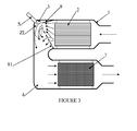
- the figure 3 schematically shows another variant of the invention.
- a compact U-shaped decontamination assembly for the depollution of the exhaust gases of a combustion engine comprises a casing 1 forming a first straight leg comprising a first catalytic bread, generally an oxidation catalyst 2, a fluidic connection having an elbow 3 at 90 ° and a second elbow 4 at 90 °.
- the mouth of gearing introduction means 5 is located in the bend 3, in order to introduce the gearbox.
- the assembly comprises a second straight branch comprising a mixer 6 and a catalyst SCR 7 for the selective catalytic reduction of the nitrogen oxides (the SCR catalyst 7 can be a particulate filter carrying a catalytic impregnation SCR).
- the figure 2 schematically presents a set of post-processing according to a U-architecture involving the invention in a preferred embodiment.
- a convergent 8 is disposed in the casing 1 between the outlet of the oxidation catalyst and the elbow 3, and opens into the elbow 3 facing the mouth of the introduction means 5, in the zone injection (ZI) of said means (as shown in dashed line on figures 2 and 3 ).
- the introduction means 5 typically comprise an injector.
- the gases leaving the convergent are directed towards the outer wall of the bend 3 so as to be confined in the bend, at the injection zone, before being distributed naturally throughout the fluid connection separating the two branches of the set bent.
- an architecture having a 90 ° elbow for example a "U" assembly architecture having two elbows at approximately 90 ° between the two branches of the "U", the reduction gear being injected in the first elbow
- this effect of confinement and turbulent mixing at the exit of the elbow is particularly marked.
- the effect of confinement will be all the more important as the radius of external curvature of the elbow is small.
- the additional mixer can, in the context of a "U" assembly architecture, be positioned upstream of the second branch of the U or at the input thereof.
- the mixer having a relatively weak mixing function to ensure may have a short length, which releases volume in the second branch for the implantation of post-processing means.
- the figure 3 schematically presents a variant of the invention in which the convergent 8 has orifices 81.
- the orifices make it possible to dose the portion of the gas stream guided by the convergent towards the elbow 3 (for example of the order of 75% of a flow given). This may slightly decrease the homogeneity of the mixture obtained but reduce the pressure loss generated by the convergent. It is thus possible by a perforated wall design of the adapted convergent to obtain the desired compromise between the quality of the mixture at the outlet of the elbow 3 and the pressure drop generated by the convergent.
- the invention has many advantages that derive directly from the technical effects mentioned above.
- the addition of a converging cone in an envelope of a post-treatment assembly has a low cost, and, in the context of an automotive application, leads to a low additional mass (typically order of 100g).
- the placement of the cone in the envelope can be further optimized by the use of a single weld joint to hold one side of the oxidation catalyst in the envelope and the attachment of the converging cone.
Landscapes
- Engineering & Computer Science (AREA)
- Chemical & Material Sciences (AREA)
- Chemical Kinetics & Catalysis (AREA)
- Health & Medical Sciences (AREA)
- Toxicology (AREA)
- Combustion & Propulsion (AREA)
- Mechanical Engineering (AREA)
- General Engineering & Computer Science (AREA)
- Materials Engineering (AREA)
- Exhaust Gas After Treatment (AREA)
Abstract
● un catalyseur d'oxydation (2);
● une embouchure d'un moyen d'introduction (5) de réducteur SCR ;
● un catalyseur SCR (7) ;
l'ensemble étant disposé dans une enveloppe (1) coudée entre le catalyseur d'oxydation (2) et le catalyseur SCR (7) ;
l'embouchure des moyens d'introduction (5) étant située dans le coude (3) de l'enveloppe, caractérisé par un convergent (8) interne à l'enveloppe (1) entre le catalyseur d'oxydation (2) et le coude (3), ledit convergent (8) débouchant en regard de l'embouchure des moyens d'introduction (5) de réducteur SCR.
Description
- L'invention porte sur le domaine des moyens de dépollution des gaz d'échappement d'un moteur à combustion.
- Les émissions polluantes des moteurs à combustion équipant les véhicules automobiles sont réglementées par des normes de plus en plus sévères. Les polluants réglementés sont, selon la technologie de moteur à combustion considérée, le monoxyde de carbone (CO), les hydrocarbures imbrûlés (HC), les oxydes d'azotes (NOx), et les particules.
- Il est connu d'employer un certain nombre de moyens de dépollution dans la ligne d'échappement des moteurs à combustion pour en limiter les émissions de polluants réglementés. Un catalyseur d'oxydation permet le traitement du monoxyde de carbone, des hydrocarbures imbrûlés, et dans certaines conditions des oxydes d'azotes ; un filtre à particules peut être employé pour le traitement des particules de suie.
- On désigne de manière générale ces dispositifs par le terme de moyens de « post-traitement » des gaz d'échappement.
- Par exemple, pour satisfaire aux normes anti-pollution sur les émissions d'oxydes d'azote (NOx), un système spécifique de post-traitement peut être introduit dans la ligne d'échappement des véhicules, notamment des véhicules équipés de moteurs à mélange pauvre, c'est-à-dire du type diesel ou à allumage commandé fonctionnant avec un mélange stratifié (mélange carburé non-homogène présentant un taux de carburant inférieur à la stoechiométrie). Pour le traitement des oxydes d'azote (NOx), on connaît des technologies de réduction catalytique sélective, ou « SCR » pour « selective catalytic reduction », qui consistent à réduire les NOx par introduction d'un agent réducteur (ou d'un précurseur d'un tel agent réducteur) dans les gaz d'échappement. Il peut par exemple s'agir d'une solution d'urée, dont la décomposition va permettre l'obtention d'ammoniac qui servira d'agent réducteur, mais également d'un réducteur ou d'un précurseur d'un tel réducteur sous forme gazeuse.
- On parlera dans la suite du présent document d'une manière générale de « réducteur » pour désigner un agent réducteur ou un précurseur d'agent réducteur.
- En outre, il est possible d'employer un filtre à particules portant une imprégnation catalytique SCR en tant que catalyseur SCR. Dans l'ensemble du présent document, il convient donc d'interpréter l'expression « catalyseur SCR » comme pouvant désigner un catalyseur dédié spécifiquement à la fonction de réduction catalytique sélective des oxydes d'azote, ou un filtre à particules portant une imprégnation catalytique de réduction catalytique sélective des oxydes d'azote.
- Classiquement, le catalyseur SCR est placé sous la caisse du véhicule équipé, loin du moteur car le réducteur injecté nécessite un long parcours dans la ligne d'échappement pour se décomposer d'une part, et des volumes libres suffisants pour être implanté d'autre part. Si la distance parcourue par le réducteur n'est pas suffisante le risque d'encrassement de la ligne d'échappement est important.
- Or, s'il est placé loin de la sortie du collecteur d'échappement du moteur, ou de la sortie de la turbine dans le cas d'un moteur suralimenté, le catalyseur SCR peut ne pas être actif dès les premières secondes de fonctionnement du véhicule, et laisse alors passer une quantité importante d'oxydes d'azote non traités. De même, l'injecteur de réducteur, qui nécessite d'atteindre un certain niveau de température pour être opérationnel (amorçage suffisant de la décomposition du précurseur d'urée sous forme liquide ou préchauffage du système de mise à disposition de réducteur gazeux), souffre de cet éloignement de la sortie du collecteur d'échappement.
- Il est connu de la demande de brevet français déposée au nom de la demanderesse sous le numéro
FR 11 51374 FR 1153159 - L'adoption d'un tel dispositif de post-traitement offre, outre des avantages en termes de performances des moyens de post-traitement, des avantages en termes d'implantation des systèmes dans le véhicule, en supprimant tout moyen de post-traitement de la zone sous-plancher du véhicule.
- Il nécessaire dans tout système SCR d'assurer un bon mélange du réducteur dans les gaz d'échappement préalablement à son arrivée sur le catalyseur SCR, afin d'assurer un traitement efficace des oxydes d'azote et d'éviter le passage dans l'atmosphère de réducteur. Dans un ensemble de dépollution compact, et notamment dans un ensemble en « U » ou en « L », la longueur et le volume disponible dans l'ensemble pour assurer la fonction de mélange sont particulièrement réduits.
- Il est connu d'employer pour favoriser ce mélange un dispositif appelé mélangeur, interposé entre le point d'injection de réducteur et le catalyseur SCR, qui vise à créer des turbulences dans les gaz d'échappement.
- Il existe de nombreux type de mélangeurs adaptés à cet usage. Les mélangeurs sont optimisés pour réduire autant que possible la longueur de la ligne d'échappement nécessaire à l'obtention d'une bonne homogénéité du mélange réducteur/gaz d'échappement. On connait par exemple au travers du document
FR2947003 - Les mélangeurs sont cependant des dispositifs souvent complexes, et adaptés à une ligne d'échappement dans laquelle les différents dispositifs de dépollutions sont disposés les uns à la suite des autres, dans une disposition longitudinale classique. La plupart des mélangeurs connus sont cylindriques et doivent être disposés dans une enveloppe ou « canning » cylindrique.
- Ces dispositifs ne sont pas donc adaptés à une architecture compacte coudée, notamment en « U » ou en « L », car le mélange ne peut pas être effectué par un mélangeur traditionnel dans des parties non droites et/ou non cylindriques. De plus ces dispositifs engendrent des pertes de charge non négligeables, qui pénalisent la performance du moteur équipé.
- L'objet de l'invention est de proposer des moyens pour assurer un mélange homogène d'un fluide introduit dans les gaz d'échappement d'un moteur à combustion, dans le cadre d'une architecture d'un dispositif de post-traitement des gaz d'échappement compact présentant une enveloppe (canning) unique et coudée, par exemple en « U » ou en « L », en tirant profit de cette configuration pour garantir la fonction de mélange de manière efficace, simple, et à un coût réduit.
- Plus précisément, l'invention porte donc sur un ensemble de post-traitement des gaz d'échappement d'un moteur à combustion, comportant, selon le sens d'écoulement des gaz d'échappement du moteur dans ledit ensemble :
- un catalyseur d'oxydation ;
- une embouchure d'un moyen d'introduction (5) de réducteur SCR ;
- un catalyseur SCR ;
- De préférence, l'entrée du convergent couvre toute la section de l'enveloppe de sorte que l'ensemble d'un flux gazeux circulant dans l'ensemble pénètre dans le convergent.
- Selon une variante de l'invention, le convergent présente des parois au moins en partie ajourées par des orifices. Une part des gaz pénétrant dans le convergent vont le traverser via les orifices. Cela limite l'efficacité du dispositif, mais réduit les pertes de charges générées. On peut ainsi obtenir le compromis souhaité, en fonction de l'application considérée, entre efficacité d'homogénéisation du mélange entre les gaz et le fluide introduit d'une part, et les pertes de charges générées d'autre part.
- Le convergent peut être soudé dans l'enveloppe par une soudure fixant également le catalyseur d'oxydation à l'enveloppe.
- De préférence, l'enveloppe coudée présente un coude sensiblement à angle droit entre le catalyseur d'oxydation et le catalyseur SCR. Un coude à 90° ou moins, en particulier s'il présente un rayon de courbure externe faible maximise l'effet de confinement des gaz sortant du convergent, et donc son efficacité.
- Selon un premier mode de réalisation, l'enveloppe présente une forme générale en « U ». De préférence, l'ensemble présente alors deux coudes sensiblement à angle droit entre le catalyseur d'oxydation et le catalyseur SCR, l'embouchure des moyens d'introduction étant située dans le premier coude.
- Selon un second mode de réalisation, l'enveloppe présente une forme générale en«L».
- L'invention est décrite plus en détail ci-après et en référence aux figures représentant schématiquement le système dans son mode de réalisation préférentiel.
- La
figure 1 présente schématiquement un ensemble de post-traitement selon une architecture en U, telle qu'envisagée dans l'état de la technique. - La
figure 2 présente schématiquement un ensemble de post-traitement selon une architecture en U mettant en jeu l'invention dans une variante préférentielle. - La
figure 3 présente schématiquement une autre variante de l'invention. - Un ensemble de dépollution compact en U, pour la dépollution des gaz d'échappement d'un moteur à combustion, comporte une enveloppe 1 formant une première branche droite comportant un premier pain catalytique, généralement un catalyseur d'oxydation 2, une liaison fluidique présentant un coude 3 à 90° puis un second coude 4 à 90°. L'embouchure de moyens d'introduction de réducteur 5 est implantée dans le coude 3, afin d'introduire du réducteur. L'ensemble comporte une seconde branche droite comportant un mélangeur 6 et un catalyseur SCR 7 pour la réduction catalytique sélective des oxydes d'azote (le catalyseur SCR 7 pouvant être un filtre à particule portant une imprégnation catalytique SCR).
- Bien que l'ensemble des figures ici présentées porte sur une architecture de dépollution en « U », l'invention est applicable à tout ensemble présentant une enveloppe coudée, et notamment à une architecture en « L » dans laquelle l'enveloppe présente un seul coude à 90° environ.
- La
figure 2 présente schématiquement un ensemble de post-traitement selon une architecture en U mettant en jeu l'invention dans une variante préférentielle. - Dans l'invention, un convergent 8 est disposé dans l'enveloppe 1 entre la sortie du catalyseur d'oxydation et le coude 3, et débouche dans le coude 3 en regard de l'embouchure des moyens d'introduction 5, dans la zone d'injection (ZI) desdits moyens (telle que représentée en pointillés sur les
figures 2 et3 ). Les moyens d'introduction 5 comportent typiquement un injecteur. - En particulier, les gaz sortant du convergent sont dirigés vers la paroi extérieure du coude 3 de sorte à être confinés dans le coude, au niveau de la zone d'injection, avant de se répartir naturellement dans l'ensemble du raccord fluidique séparant les deux branches de l'ensemble coudé. Dans une architecture présentant un coude à 90° (par exemple une architecture d'ensemble en « U » présentant deux coudes à environ 90° entre les deux branches du « U », l'injection de réducteur étant réalisée dans le premier coude), cet effet de confinement et de mélange turbulent en sortie du coude est particulièrement marqué. L'effet de confinement sera d'autant plus important que le rayon de courbure extérieur du coude est faible.
- On obtient ainsi une répartition assez homogène du réducteur dans les gaz, permettant de se passer d'un mélangeur additionnel ou au moins de se contenter pour garantir un mélange homogène d'un mélangeur présentant une faible efficacité en termes de mélange, mais générant de faibles pertes de charge. Le mélangeur additionnel, s'il est nécessaire, peut dans le cadre d'une architecture d'ensemble en « U » être positionné en amont de la seconde branche du U ou en entrée de celle-ci. Le mélangeur ayant une fonction de mélange assez faible à assurer, pourra présenter une faible longueur, ce qui libère du volume dans la seconde branche pour l'implantation de moyens de post-traitement.
- La
figure 3 présente schématiquement une variante de l'invention dans laquelle le convergent 8 présente des orifices 81. Les orifices permettent de doser la part du flux gazeux guidés par le convergent vers le coude 3 (par exemple de l'ordre de 75% d'un flux donné). Cela peut diminuer légèrement l'homogénéité du mélange obtenu mais réduit la perte de charge généré par le convergent. On peut ainsi par une conception de parois ajourées du convergent adaptée obtenir le compromis souhaité entre la qualité du mélange en sortie du coude 3 et la perte de charge générée par le convergent. - L'invention présente de multiples avantages qui découlent directement des effets techniques précédemment évoqués. En outre, l'ajout d'un cône convergent dans une enveloppe d'un ensemble de post-traitement a un faible coût de revient, et, dans le cadre d'une application automobile, entraine une masse supplémentaire faible (typiquement de l'ordre de 100g). La mise en place du cône dans l'enveloppe peut en outre être optimisée par l'emploi d'un unique joint de soudure pour le maintien d'un côté du catalyseur d'oxydation dans l'enveloppe et la fixation du cône convergent.
l'embouchure des moyens d'introduction étant située dans le coude de l'enveloppe, l'ensemble comportant un convergent interne à l'enveloppe entre le catalyseur d'oxydation et le coude, ledit convergent débouchant en regard de l'embouchure des moyens d'introduction de réducteur SCR.
Les gaz sortent ainsi du convergent dans la zone d'injection de l'injecteur, et sont confinés dans le coude avant de se répartir de manière assez homogène entre le coude et le catalyseur SCR.
Claims (8)
- Ensemble de post-traitement des gaz d'échappement d'un moteur à combustion, comportant, selon le sens d'écoulement des gaz d'échappement du moteur dans ledit ensemble :• un catalyseur d'oxydation (2);• une embouchure d'un moyen d'introduction (5) de réducteur SCR ;• un catalyseur SCR (7) ;l'ensemble étant disposé dans une enveloppe (1) coudée entre le catalyseur d'oxydation (2) et le catalyseur SCR (7) ;
l'embouchure des moyens d'introduction (5) étant située dans le coude (3) de l'enveloppe, caractérisé par un convergent (8) interne à l'enveloppe (1) entre le catalyseur d'oxydation (2) et le coude (3), ledit convergent (8) débouchant en regard de l'embouchure des moyens d'introduction (5) de réducteur SCR. - Ensemble selon la revendication 1, dans lequel l'entrée du convergent (8) couvre toute la section de l'enveloppe 1 de sorte que l'ensemble d'un flux gazeux circulant dans l'ensemble pénètre dans le convergent.
- Ensemble selon la revendication 1 ou la revendication 2 dans lequel le convergent (8) présente des parois au moins en partie ajourées par des orifices (81).
- Ensemble selon l'une quelconque des revendications précédentes, dans lequel le convergent (8) est soudé dans l'enveloppe par une soudure fixant également le catalyseur d'oxydation (2) à l'enveloppe (1).
- Ensemble selon l'une des revendications précédentes, dans lequel l'enveloppe (1) coudée présente un coude (3) sensiblement à angle droit entre le catalyseur d'oxydation (2) et le catalyseur SCR (7).
- Ensemble selon l'une des revendications précédentes, dans lequel l'enveloppe (1) présente une forme générale en « U ».
- Ensemble selon la revendication 6, dans lequel l'ensemble présente deux coudes sensiblement à angle droit entre le catalyseur d'oxydation (2) et le catalyseur SCR (7), l'embouchure des moyens d'introduction (5) étant située dans le premier coude (3).
- Ensemble selon l'une des revendications 1 à 5, dans lequel l'enveloppe (1) présente une forme générale en « L ».
Applications Claiming Priority (1)
| Application Number | Priority Date | Filing Date | Title |
|---|---|---|---|
| FR1156896A FR2978492B1 (fr) | 2011-07-28 | 2011-07-28 | Ensemble coude de post-traitement des gaz d'echappement d'un moteur a combustion comportant un convergent interne |
Publications (2)
| Publication Number | Publication Date |
|---|---|
| EP2551482A1 true EP2551482A1 (fr) | 2013-01-30 |
| EP2551482B1 EP2551482B1 (fr) | 2015-01-21 |
Family
ID=46210168
Family Applications (1)
| Application Number | Title | Priority Date | Filing Date |
|---|---|---|---|
| EP12172131.0A Revoked EP2551482B1 (fr) | 2011-07-28 | 2012-06-15 | Ensemble coude de post-traitement des gaz d'echappement d'un moteur à combustion comportant un convergent interne |
Country Status (2)
| Country | Link |
|---|---|
| EP (1) | EP2551482B1 (fr) |
| FR (1) | FR2978492B1 (fr) |
Cited By (5)
| Publication number | Priority date | Publication date | Assignee | Title |
|---|---|---|---|---|
| DE102014206907A1 (de) * | 2014-04-10 | 2015-10-29 | Bayerische Motoren Werke Aktiengesellschaft | Abgasreinigungsanlage für Dieselmotoren |
| EP2985434A1 (fr) * | 2014-08-14 | 2016-02-17 | MAN Truck & Bus Österreich AG | Dispositif de nettoyage de gaz d'échappement pour un véhicule, notamment pour un véhicule utilitaire |
| US20170044957A1 (en) * | 2014-05-20 | 2017-02-16 | Hino Motors, Ltd. | Mixing structure |
| EP3181850A1 (fr) * | 2011-08-25 | 2017-06-21 | Volkswagen Aktiengesellschaft | Dispositif de traitement des gaz d'échappement, procédé de traitement des gaz d'échappement et véhicule automobile |
| CN107438480A (zh) * | 2014-07-29 | 2017-12-05 | 康明公司 | 催化剂模块及其应用 |
Families Citing this family (11)
| Publication number | Priority date | Publication date | Assignee | Title |
|---|---|---|---|---|
| WO2018226626A1 (fr) | 2017-06-06 | 2018-12-13 | Cummins Emission Solutions Inc. | Systèmes et procédés de mélange de gaz d'échappement et d'agent réducteur dans un système de post-traitement |
| US12503969B2 (en) | 2019-12-03 | 2025-12-23 | Cummins Emission Solutions Inc. | Reductant delivery system for exhaust gas aftertreatment system |
| CN120132644A (zh) | 2020-02-27 | 2025-06-13 | 康明斯排放处理公司 | 用于后处理系统中的混合器 |
| US11828214B2 (en) | 2020-05-08 | 2023-11-28 | Cummins Emission Solutions Inc. | Configurable aftertreatment systems including a housing |
| WO2022087279A1 (fr) | 2020-10-22 | 2022-04-28 | Cummins Emission Solutions Inc. | Système de post-traitement des gaz d'échappement |
| CN116782991A (zh) | 2021-02-02 | 2023-09-19 | 康明斯排放处理公司 | 排气后处理系统 |
| US12123337B2 (en) | 2021-03-18 | 2024-10-22 | Cummins Emission Solutions Inc. | Aftertreatment systems |
| GB2622178A (en) | 2021-07-27 | 2024-03-06 | Cummins Emission Solutions Inc | Exhaust gas aftertreatment system |
| GB2626449B (en) | 2021-08-23 | 2025-07-16 | Cummins Emission Solutions Inc | Outlet sampling system for aftertreatment system |
| USD1042544S1 (en) | 2022-04-21 | 2024-09-17 | Cummins Emission Solutions Inc. | Aftertreatment system |
| USD1042545S1 (en) | 2022-04-21 | 2024-09-17 | Cummins Emission Solutions Inc. | Aftertreatment system |
Citations (4)
| Publication number | Priority date | Publication date | Assignee | Title |
|---|---|---|---|---|
| WO2001004466A1 (fr) * | 1999-07-08 | 2001-01-18 | Johnson Matthey Public Limited Company | Dispositif et procede permettant d'enlever les particules de suie des gaz d'echappement produits par les processus de combustion |
| JP2006132393A (ja) * | 2004-11-04 | 2006-05-25 | Mitsubishi Fuso Truck & Bus Corp | 内燃機関の排気浄化装置 |
| WO2009024815A2 (fr) * | 2007-08-17 | 2009-02-26 | Emcon Technologies Germany (Augsburg) Gmbh | Système d'échappement |
| US20100083643A1 (en) * | 2007-03-12 | 2010-04-08 | Miwa Hayashi | Exhaust gas purification apparatus for internal combustion engine |
-
2011
- 2011-07-28 FR FR1156896A patent/FR2978492B1/fr not_active Expired - Fee Related
-
2012
- 2012-06-15 EP EP12172131.0A patent/EP2551482B1/fr not_active Revoked
Patent Citations (4)
| Publication number | Priority date | Publication date | Assignee | Title |
|---|---|---|---|---|
| WO2001004466A1 (fr) * | 1999-07-08 | 2001-01-18 | Johnson Matthey Public Limited Company | Dispositif et procede permettant d'enlever les particules de suie des gaz d'echappement produits par les processus de combustion |
| JP2006132393A (ja) * | 2004-11-04 | 2006-05-25 | Mitsubishi Fuso Truck & Bus Corp | 内燃機関の排気浄化装置 |
| US20100083643A1 (en) * | 2007-03-12 | 2010-04-08 | Miwa Hayashi | Exhaust gas purification apparatus for internal combustion engine |
| WO2009024815A2 (fr) * | 2007-08-17 | 2009-02-26 | Emcon Technologies Germany (Augsburg) Gmbh | Système d'échappement |
Cited By (11)
| Publication number | Priority date | Publication date | Assignee | Title |
|---|---|---|---|---|
| EP3181850A1 (fr) * | 2011-08-25 | 2017-06-21 | Volkswagen Aktiengesellschaft | Dispositif de traitement des gaz d'échappement, procédé de traitement des gaz d'échappement et véhicule automobile |
| EP3181850B1 (fr) | 2011-08-25 | 2019-10-09 | Volkswagen Aktiengesellschaft | Dispositif de traitement des gaz d'échappement, procédé de traitement des gaz d'échappement et véhicule automobile |
| DE102014206907A1 (de) * | 2014-04-10 | 2015-10-29 | Bayerische Motoren Werke Aktiengesellschaft | Abgasreinigungsanlage für Dieselmotoren |
| DE102014206907B4 (de) | 2014-04-10 | 2025-10-09 | Bayerische Motoren Werke Aktiengesellschaft | Abgasreinigungsanlage für Dieselmotoren |
| US20170044957A1 (en) * | 2014-05-20 | 2017-02-16 | Hino Motors, Ltd. | Mixing structure |
| US10138788B2 (en) * | 2014-05-20 | 2018-11-27 | Hino Motors, Ltd. | Mixing structure |
| CN107438480A (zh) * | 2014-07-29 | 2017-12-05 | 康明公司 | 催化剂模块及其应用 |
| CN107438480B (zh) * | 2014-07-29 | 2020-07-14 | 康明公司 | 催化剂模块及其应用 |
| EP2985434A1 (fr) * | 2014-08-14 | 2016-02-17 | MAN Truck & Bus Österreich AG | Dispositif de nettoyage de gaz d'échappement pour un véhicule, notamment pour un véhicule utilitaire |
| CN105370349A (zh) * | 2014-08-14 | 2016-03-02 | 曼卡车和巴士奥地利股份公司 | 用于车辆的、尤其用于商用车辆的废气净化装置 |
| CN105370349B (zh) * | 2014-08-14 | 2019-06-21 | 曼卡车和巴士奥地利股份公司 | 用于车辆的、尤其用于商用车辆的废气净化装置 |
Also Published As
| Publication number | Publication date |
|---|---|
| FR2978492B1 (fr) | 2013-08-02 |
| FR2978492A1 (fr) | 2013-02-01 |
| EP2551482B1 (fr) | 2015-01-21 |
Similar Documents
| Publication | Publication Date | Title |
|---|---|---|
| EP2551482B1 (fr) | Ensemble coude de post-traitement des gaz d'echappement d'un moteur à combustion comportant un convergent interne | |
| EP2500538B1 (fr) | Ensemble compact coudé de post-traitement de gaz d'échappement doté d'un bossage formant mélangeur de réducteur scr | |
| EP2546488B1 (fr) | Ensemble coudé de post-traitement des gaz d'échappement d'un moteur à combustion interne comportant un répartiteur d'agent réducteur par impacteur | |
| EP2676016B1 (fr) | Ensemble de post-traitement des gaz d'echappement d'un moteur a combustion suralimente, et vehicule automobile comportant un tel ensemble | |
| EP2551481B1 (fr) | Ensemble de traitement des gaz d'echappement d'un moteur à combustion comportant une boîte d'introduction et de prémélange d'un fluide | |
| US20110225969A1 (en) | Compressor bypass to exhaust for particulate trap regeneration | |
| FR3098854A1 (fr) | Système de dépollution de gaz d’échappement | |
| FR2975129A1 (fr) | Systeme comportant un moteur a combustion, un ensemble en " u " de traitement des gaz d'echappement, et un ecran thermique optimise | |
| FR3106369A3 (fr) | Mélangeur et système de post-traitement d’échappement pour un moteur | |
| FR2947004A1 (fr) | Ligne d'echappement avec dispositif de traitement des oxydes d'azote. | |
| FR2945576A1 (fr) | Melangeur, dispositif de depollution et ligne d'echappement equipee de ce melangeur. | |
| FR2928687A1 (fr) | Ligne d'echappement avec injecteur de reactif | |
| EP2145087B1 (fr) | Raccord d'un turbocompresseur avec un catalyseur d'oxydation d'une ligne d'echappement d'un moteur a combustion interne | |
| EP2126299A1 (fr) | Ligne d'echappement de moteur a combustion interne pourvue de moyens de reduction d'oxydes d'azote | |
| FR3037101A1 (fr) | Ligne d’echappement d’un moteur thermique | |
| FR3100839A1 (fr) | Ensemble comprenant un moteur à combustion interne avec un compresseur électrique et un élément chauffant | |
| FR2900440A3 (fr) | Injecteur d'un agent reducteur dans un conduit d'echappement | |
| FR3066541A1 (fr) | Systeme de post-traitement des gaz d'echappement d'un moteur a combustion interne | |
| US20210010407A1 (en) | Reductant delivery conduit for a reductant storage tank | |
| FR3040193B1 (fr) | Systeme de reduction catalytique selective | |
| FR2968709A1 (fr) | Methode d'epuration des gaz d'echappement produits par un moteur thermique equipant un vehicule automobile | |
| FR3142508A1 (fr) | Ligne d’échappement pour moteur à hydrogène | |
| FR2995349A1 (fr) | Dispositif de traitement des emissions polluantes d'un moteur thermique par reduction catalytique, diminuant l'apport en reducteur embarque | |
| FR2986826A1 (fr) | Dispositif de traitement des gaz d'echappement d'un moteur a combustion et vehicule automobile associe | |
| FR2937681A3 (fr) | Dispositif de melange d'un agent reducteur aux gaz d'echappement d'un moteur en amont d'un organe de depollution et ligne d'echappement munie de ce dispositif |
Legal Events
| Date | Code | Title | Description |
|---|---|---|---|
| PUAI | Public reference made under article 153(3) epc to a published international application that has entered the european phase |
Free format text: ORIGINAL CODE: 0009012 |
|
| AK | Designated contracting states |
Kind code of ref document: A1 Designated state(s): AL AT BE BG CH CY CZ DE DK EE ES FI FR GB GR HR HU IE IS IT LI LT LU LV MC MK MT NL NO PL PT RO RS SE SI SK SM TR |
|
| AX | Request for extension of the european patent |
Extension state: BA ME |
|
| 17P | Request for examination filed |
Effective date: 20130325 |
|
| 17Q | First examination report despatched |
Effective date: 20130823 |
|
| GRAP | Despatch of communication of intention to grant a patent |
Free format text: ORIGINAL CODE: EPIDOSNIGR1 |
|
| INTG | Intention to grant announced |
Effective date: 20140821 |
|
| GRAS | Grant fee paid |
Free format text: ORIGINAL CODE: EPIDOSNIGR3 |
|
| GRAA | (expected) grant |
Free format text: ORIGINAL CODE: 0009210 |
|
| AK | Designated contracting states |
Kind code of ref document: B1 Designated state(s): AL AT BE BG CH CY CZ DE DK EE ES FI FR GB GR HR HU IE IS IT LI LT LU LV MC MK MT NL NO PL PT RO RS SE SI SK SM TR |
|
| REG | Reference to a national code |
Ref country code: GB Ref legal event code: FG4D Free format text: NOT ENGLISH |
|
| REG | Reference to a national code |
Ref country code: CH Ref legal event code: EP |
|
| REG | Reference to a national code |
Ref country code: IE Ref legal event code: FG4D Free format text: LANGUAGE OF EP DOCUMENT: FRENCH |
|
| REG | Reference to a national code |
Ref country code: DE Ref legal event code: R096 Ref document number: 602012005003 Country of ref document: DE Effective date: 20150305 |
|
| REG | Reference to a national code |
Ref country code: AT Ref legal event code: REF Ref document number: 709299 Country of ref document: AT Kind code of ref document: T Effective date: 20150315 |
|
| REG | Reference to a national code |
Ref country code: FR Ref legal event code: PLFP Year of fee payment: 4 |
|
| REG | Reference to a national code |
Ref country code: NL Ref legal event code: VDEP Effective date: 20150121 |
|
| REG | Reference to a national code |
Ref country code: AT Ref legal event code: MK05 Ref document number: 709299 Country of ref document: AT Kind code of ref document: T Effective date: 20150121 |
|
| REG | Reference to a national code |
Ref country code: LT Ref legal event code: MG4D |
|
| PG25 | Lapsed in a contracting state [announced via postgrant information from national office to epo] |
Ref country code: LT Free format text: LAPSE BECAUSE OF FAILURE TO SUBMIT A TRANSLATION OF THE DESCRIPTION OR TO PAY THE FEE WITHIN THE PRESCRIBED TIME-LIMIT Effective date: 20150121 Ref country code: BG Free format text: LAPSE BECAUSE OF FAILURE TO SUBMIT A TRANSLATION OF THE DESCRIPTION OR TO PAY THE FEE WITHIN THE PRESCRIBED TIME-LIMIT Effective date: 20150421 Ref country code: HR Free format text: LAPSE BECAUSE OF FAILURE TO SUBMIT A TRANSLATION OF THE DESCRIPTION OR TO PAY THE FEE WITHIN THE PRESCRIBED TIME-LIMIT Effective date: 20150121 Ref country code: NO Free format text: LAPSE BECAUSE OF FAILURE TO SUBMIT A TRANSLATION OF THE DESCRIPTION OR TO PAY THE FEE WITHIN THE PRESCRIBED TIME-LIMIT Effective date: 20150421 Ref country code: FI Free format text: LAPSE BECAUSE OF FAILURE TO SUBMIT A TRANSLATION OF THE DESCRIPTION OR TO PAY THE FEE WITHIN THE PRESCRIBED TIME-LIMIT Effective date: 20150121 Ref country code: ES Free format text: LAPSE BECAUSE OF FAILURE TO SUBMIT A TRANSLATION OF THE DESCRIPTION OR TO PAY THE FEE WITHIN THE PRESCRIBED TIME-LIMIT Effective date: 20150121 Ref country code: SE Free format text: LAPSE BECAUSE OF FAILURE TO SUBMIT A TRANSLATION OF THE DESCRIPTION OR TO PAY THE FEE WITHIN THE PRESCRIBED TIME-LIMIT Effective date: 20150121 |
|
| PG25 | Lapsed in a contracting state [announced via postgrant information from national office to epo] |
Ref country code: IS Free format text: LAPSE BECAUSE OF FAILURE TO SUBMIT A TRANSLATION OF THE DESCRIPTION OR TO PAY THE FEE WITHIN THE PRESCRIBED TIME-LIMIT Effective date: 20150521 Ref country code: RS Free format text: LAPSE BECAUSE OF FAILURE TO SUBMIT A TRANSLATION OF THE DESCRIPTION OR TO PAY THE FEE WITHIN THE PRESCRIBED TIME-LIMIT Effective date: 20150121 Ref country code: LV Free format text: LAPSE BECAUSE OF FAILURE TO SUBMIT A TRANSLATION OF THE DESCRIPTION OR TO PAY THE FEE WITHIN THE PRESCRIBED TIME-LIMIT Effective date: 20150121 Ref country code: AT Free format text: LAPSE BECAUSE OF FAILURE TO SUBMIT A TRANSLATION OF THE DESCRIPTION OR TO PAY THE FEE WITHIN THE PRESCRIBED TIME-LIMIT Effective date: 20150121 Ref country code: PL Free format text: LAPSE BECAUSE OF FAILURE TO SUBMIT A TRANSLATION OF THE DESCRIPTION OR TO PAY THE FEE WITHIN THE PRESCRIBED TIME-LIMIT Effective date: 20150121 Ref country code: NL Free format text: LAPSE BECAUSE OF FAILURE TO SUBMIT A TRANSLATION OF THE DESCRIPTION OR TO PAY THE FEE WITHIN THE PRESCRIBED TIME-LIMIT Effective date: 20150121 Ref country code: GR Free format text: LAPSE BECAUSE OF FAILURE TO SUBMIT A TRANSLATION OF THE DESCRIPTION OR TO PAY THE FEE WITHIN THE PRESCRIBED TIME-LIMIT Effective date: 20150422 |
|
| REG | Reference to a national code |
Ref country code: DE Ref legal event code: R026 Ref document number: 602012005003 Country of ref document: DE |
|
| PLBI | Opposition filed |
Free format text: ORIGINAL CODE: 0009260 |
|
| PG25 | Lapsed in a contracting state [announced via postgrant information from national office to epo] |
Ref country code: CZ Free format text: LAPSE BECAUSE OF FAILURE TO SUBMIT A TRANSLATION OF THE DESCRIPTION OR TO PAY THE FEE WITHIN THE PRESCRIBED TIME-LIMIT Effective date: 20150121 Ref country code: EE Free format text: LAPSE BECAUSE OF FAILURE TO SUBMIT A TRANSLATION OF THE DESCRIPTION OR TO PAY THE FEE WITHIN THE PRESCRIBED TIME-LIMIT Effective date: 20150121 Ref country code: RO Free format text: LAPSE BECAUSE OF FAILURE TO SUBMIT A TRANSLATION OF THE DESCRIPTION OR TO PAY THE FEE WITHIN THE PRESCRIBED TIME-LIMIT Effective date: 20150121 Ref country code: DK Free format text: LAPSE BECAUSE OF FAILURE TO SUBMIT A TRANSLATION OF THE DESCRIPTION OR TO PAY THE FEE WITHIN THE PRESCRIBED TIME-LIMIT Effective date: 20150121 Ref country code: SK Free format text: LAPSE BECAUSE OF FAILURE TO SUBMIT A TRANSLATION OF THE DESCRIPTION OR TO PAY THE FEE WITHIN THE PRESCRIBED TIME-LIMIT Effective date: 20150121 |
|
| 26 | Opposition filed |
Opponent name: TENNECO GMBH Effective date: 20151016 |
|
| PLAX | Notice of opposition and request to file observation + time limit sent |
Free format text: ORIGINAL CODE: EPIDOSNOBS2 |
|
| PG25 | Lapsed in a contracting state [announced via postgrant information from national office to epo] |
Ref country code: IT Free format text: LAPSE BECAUSE OF FAILURE TO SUBMIT A TRANSLATION OF THE DESCRIPTION OR TO PAY THE FEE WITHIN THE PRESCRIBED TIME-LIMIT Effective date: 20150121 |
|
| REG | Reference to a national code |
Ref country code: DE Ref legal event code: R084 Ref document number: 602012005003 Country of ref document: DE |
|
| PG25 | Lapsed in a contracting state [announced via postgrant information from national office to epo] |
Ref country code: MC Free format text: LAPSE BECAUSE OF FAILURE TO SUBMIT A TRANSLATION OF THE DESCRIPTION OR TO PAY THE FEE WITHIN THE PRESCRIBED TIME-LIMIT Effective date: 20150121 |
|
| REG | Reference to a national code |
Ref country code: CH Ref legal event code: PL |
|
| REG | Reference to a national code |
Ref country code: GB Ref legal event code: 746 Effective date: 20160119 |
|
| PG25 | Lapsed in a contracting state [announced via postgrant information from national office to epo] |
Ref country code: LU Free format text: LAPSE BECAUSE OF FAILURE TO SUBMIT A TRANSLATION OF THE DESCRIPTION OR TO PAY THE FEE WITHIN THE PRESCRIBED TIME-LIMIT Effective date: 20150615 Ref country code: SI Free format text: LAPSE BECAUSE OF FAILURE TO SUBMIT A TRANSLATION OF THE DESCRIPTION OR TO PAY THE FEE WITHIN THE PRESCRIBED TIME-LIMIT Effective date: 20150121 |
|
| REG | Reference to a national code |
Ref country code: IE Ref legal event code: MM4A |
|
| PLBB | Reply of patent proprietor to notice(s) of opposition received |
Free format text: ORIGINAL CODE: EPIDOSNOBS3 |
|
| PG25 | Lapsed in a contracting state [announced via postgrant information from national office to epo] |
Ref country code: CH Free format text: LAPSE BECAUSE OF NON-PAYMENT OF DUE FEES Effective date: 20150630 Ref country code: IE Free format text: LAPSE BECAUSE OF NON-PAYMENT OF DUE FEES Effective date: 20150615 Ref country code: LI Free format text: LAPSE BECAUSE OF NON-PAYMENT OF DUE FEES Effective date: 20150630 |
|
| REG | Reference to a national code |
Ref country code: FR Ref legal event code: PLFP Year of fee payment: 5 |
|
| PG25 | Lapsed in a contracting state [announced via postgrant information from national office to epo] |
Ref country code: MT Free format text: LAPSE BECAUSE OF FAILURE TO SUBMIT A TRANSLATION OF THE DESCRIPTION OR TO PAY THE FEE WITHIN THE PRESCRIBED TIME-LIMIT Effective date: 20150121 |
|
| REG | Reference to a national code |
Ref country code: FR Ref legal event code: PLFP Year of fee payment: 6 |
|
| PG25 | Lapsed in a contracting state [announced via postgrant information from national office to epo] |
Ref country code: HU Free format text: LAPSE BECAUSE OF FAILURE TO SUBMIT A TRANSLATION OF THE DESCRIPTION OR TO PAY THE FEE WITHIN THE PRESCRIBED TIME-LIMIT; INVALID AB INITIO Effective date: 20120615 Ref country code: SM Free format text: LAPSE BECAUSE OF FAILURE TO SUBMIT A TRANSLATION OF THE DESCRIPTION OR TO PAY THE FEE WITHIN THE PRESCRIBED TIME-LIMIT Effective date: 20150121 |
|
| PG25 | Lapsed in a contracting state [announced via postgrant information from national office to epo] |
Ref country code: CY Free format text: LAPSE BECAUSE OF FAILURE TO SUBMIT A TRANSLATION OF THE DESCRIPTION OR TO PAY THE FEE WITHIN THE PRESCRIBED TIME-LIMIT Effective date: 20150121 |
|
| PG25 | Lapsed in a contracting state [announced via postgrant information from national office to epo] |
Ref country code: BE Free format text: LAPSE BECAUSE OF NON-PAYMENT OF DUE FEES Effective date: 20150630 |
|
| RAP2 | Party data changed (patent owner data changed or rights of a patent transferred) |
Owner name: PSA AUTOMOBILES SA |
|
| PG25 | Lapsed in a contracting state [announced via postgrant information from national office to epo] |
Ref country code: TR Free format text: LAPSE BECAUSE OF FAILURE TO SUBMIT A TRANSLATION OF THE DESCRIPTION OR TO PAY THE FEE WITHIN THE PRESCRIBED TIME-LIMIT Effective date: 20150121 |
|
| APBM | Appeal reference recorded |
Free format text: ORIGINAL CODE: EPIDOSNREFNO |
|
| APBP | Date of receipt of notice of appeal recorded |
Free format text: ORIGINAL CODE: EPIDOSNNOA2O |
|
| APAH | Appeal reference modified |
Free format text: ORIGINAL CODE: EPIDOSCREFNO |
|
| APAW | Appeal reference deleted |
Free format text: ORIGINAL CODE: EPIDOSDREFNO |
|
| APBM | Appeal reference recorded |
Free format text: ORIGINAL CODE: EPIDOSNREFNO |
|
| APBP | Date of receipt of notice of appeal recorded |
Free format text: ORIGINAL CODE: EPIDOSNNOA2O |
|
| APBQ | Date of receipt of statement of grounds of appeal recorded |
Free format text: ORIGINAL CODE: EPIDOSNNOA3O |
|
| APBQ | Date of receipt of statement of grounds of appeal recorded |
Free format text: ORIGINAL CODE: EPIDOSNNOA3O |
|
| REG | Reference to a national code |
Ref country code: FR Ref legal event code: PLFP Year of fee payment: 7 |
|
| PG25 | Lapsed in a contracting state [announced via postgrant information from national office to epo] |
Ref country code: MK Free format text: LAPSE BECAUSE OF FAILURE TO SUBMIT A TRANSLATION OF THE DESCRIPTION OR TO PAY THE FEE WITHIN THE PRESCRIBED TIME-LIMIT Effective date: 20150121 Ref country code: PT Free format text: LAPSE BECAUSE OF FAILURE TO SUBMIT A TRANSLATION OF THE DESCRIPTION OR TO PAY THE FEE WITHIN THE PRESCRIBED TIME-LIMIT Effective date: 20150121 |
|
| REG | Reference to a national code |
Ref country code: FR Ref legal event code: CA Effective date: 20180312 Ref country code: FR Ref legal event code: CD Owner name: PEUGEOT CITROEN AUTOMOBILES SA, FR Effective date: 20180312 |
|
| PG25 | Lapsed in a contracting state [announced via postgrant information from national office to epo] |
Ref country code: AL Free format text: LAPSE BECAUSE OF FAILURE TO SUBMIT A TRANSLATION OF THE DESCRIPTION OR TO PAY THE FEE WITHIN THE PRESCRIBED TIME-LIMIT Effective date: 20150121 |
|
| RAP2 | Party data changed (patent owner data changed or rights of a patent transferred) |
Owner name: FAURECIA SYSTEMES D'ECHAPPEMENT |
|
| REG | Reference to a national code |
Ref country code: GB Ref legal event code: 732E Free format text: REGISTERED BETWEEN 20201022 AND 20201028 |
|
| REG | Reference to a national code |
Ref country code: DE Ref legal event code: R064 Ref document number: 602012005003 Country of ref document: DE Ref country code: DE Ref legal event code: R103 Ref document number: 602012005003 Country of ref document: DE |
|
| APBU | Appeal procedure closed |
Free format text: ORIGINAL CODE: EPIDOSNNOA9O |
|
| REG | Reference to a national code |
Ref country code: DE Ref legal event code: R081 Ref document number: 602012005003 Country of ref document: DE Owner name: FAURECIA SYSTEMES D'ECHAPPEMENT, FR Free format text: FORMER OWNER: PEUGEOT CITROEN AUTOMOBILES S.A., VELIZY-VILLACOUBLAY, FR |
|
| REG | Reference to a national code |
Ref country code: DE Ref legal event code: R082 Ref document number: 602012005003 Country of ref document: DE Representative=s name: LAVOIX MUNICH, DE Ref country code: DE Ref legal event code: R081 Ref document number: 602012005003 Country of ref document: DE Owner name: FAURECIA SYSTEMES D'ECHAPPEMENT, FR Free format text: FORMER OWNER: PSA AUTOMOBILES SA, POISSY, FR |
|
| RDAF | Communication despatched that patent is revoked |
Free format text: ORIGINAL CODE: EPIDOSNREV1 |
|
| RDAG | Patent revoked |
Free format text: ORIGINAL CODE: 0009271 |
|
| STAA | Information on the status of an ep patent application or granted ep patent |
Free format text: STATUS: PATENT REVOKED |
|
| PGFP | Annual fee paid to national office [announced via postgrant information from national office to epo] |
Ref country code: FR Payment date: 20210519 Year of fee payment: 10 Ref country code: DE Payment date: 20210519 Year of fee payment: 10 |
|
| REG | Reference to a national code |
Ref country code: FI Ref legal event code: MGE |
|
| 27W | Patent revoked |
Effective date: 20210315 |
|
| GBPR | Gb: patent revoked under art. 102 of the ep convention designating the uk as contracting state |
Effective date: 20210315 |
|
| PGFP | Annual fee paid to national office [announced via postgrant information from national office to epo] |
Ref country code: GB Payment date: 20210519 Year of fee payment: 10 |