EP2551478A1 - System for utilizing waste heat of internal combustion engine, and motor generator device using the system - Google Patents
System for utilizing waste heat of internal combustion engine, and motor generator device using the system Download PDFInfo
- Publication number
- EP2551478A1 EP2551478A1 EP11759366A EP11759366A EP2551478A1 EP 2551478 A1 EP2551478 A1 EP 2551478A1 EP 11759366 A EP11759366 A EP 11759366A EP 11759366 A EP11759366 A EP 11759366A EP 2551478 A1 EP2551478 A1 EP 2551478A1
- Authority
- EP
- European Patent Office
- Prior art keywords
- motor
- generator
- expander
- electric power
- rankine
- Prior art date
- Legal status (The legal status is an assumption and is not a legal conclusion. Google has not performed a legal analysis and makes no representation as to the accuracy of the status listed.)
- Granted
Links
Images


Classifications
-
- F—MECHANICAL ENGINEERING; LIGHTING; HEATING; WEAPONS; BLASTING
- F01—MACHINES OR ENGINES IN GENERAL; ENGINE PLANTS IN GENERAL; STEAM ENGINES
- F01K—STEAM ENGINE PLANTS; STEAM ACCUMULATORS; ENGINE PLANTS NOT OTHERWISE PROVIDED FOR; ENGINES USING SPECIAL WORKING FLUIDS OR CYCLES
- F01K23/00—Plants characterised by more than one engine delivering power external to the plant, the engines being driven by different fluids
- F01K23/02—Plants characterised by more than one engine delivering power external to the plant, the engines being driven by different fluids the engine cycles being thermally coupled
- F01K23/06—Plants characterised by more than one engine delivering power external to the plant, the engines being driven by different fluids the engine cycles being thermally coupled combustion heat from one cycle heating the fluid in another cycle
- F01K23/065—Plants characterised by more than one engine delivering power external to the plant, the engines being driven by different fluids the engine cycles being thermally coupled combustion heat from one cycle heating the fluid in another cycle the combustion taking place in an internal combustion piston engine, e.g. a diesel engine
-
- F—MECHANICAL ENGINEERING; LIGHTING; HEATING; WEAPONS; BLASTING
- F01—MACHINES OR ENGINES IN GENERAL; ENGINE PLANTS IN GENERAL; STEAM ENGINES
- F01K—STEAM ENGINE PLANTS; STEAM ACCUMULATORS; ENGINE PLANTS NOT OTHERWISE PROVIDED FOR; ENGINES USING SPECIAL WORKING FLUIDS OR CYCLES
- F01K23/00—Plants characterised by more than one engine delivering power external to the plant, the engines being driven by different fluids
- F01K23/02—Plants characterised by more than one engine delivering power external to the plant, the engines being driven by different fluids the engine cycles being thermally coupled
- F01K23/06—Plants characterised by more than one engine delivering power external to the plant, the engines being driven by different fluids the engine cycles being thermally coupled combustion heat from one cycle heating the fluid in another cycle
- F01K23/10—Plants characterised by more than one engine delivering power external to the plant, the engines being driven by different fluids the engine cycles being thermally coupled combustion heat from one cycle heating the fluid in another cycle with exhaust fluid of one cycle heating the fluid in another cycle
-
- F—MECHANICAL ENGINEERING; LIGHTING; HEATING; WEAPONS; BLASTING
- F01—MACHINES OR ENGINES IN GENERAL; ENGINE PLANTS IN GENERAL; STEAM ENGINES
- F01D—NON-POSITIVE DISPLACEMENT MACHINES OR ENGINES, e.g. STEAM TURBINES
- F01D15/00—Adaptations of machines or engines for special use; Combinations of engines with devices driven thereby
- F01D15/08—Adaptations for driving, or combinations with, pumps
-
- F—MECHANICAL ENGINEERING; LIGHTING; HEATING; WEAPONS; BLASTING
- F01—MACHINES OR ENGINES IN GENERAL; ENGINE PLANTS IN GENERAL; STEAM ENGINES
- F01D—NON-POSITIVE DISPLACEMENT MACHINES OR ENGINES, e.g. STEAM TURBINES
- F01D15/00—Adaptations of machines or engines for special use; Combinations of engines with devices driven thereby
- F01D15/10—Adaptations for driving, or combinations with, electric generators
-
- F—MECHANICAL ENGINEERING; LIGHTING; HEATING; WEAPONS; BLASTING
- F01—MACHINES OR ENGINES IN GENERAL; ENGINE PLANTS IN GENERAL; STEAM ENGINES
- F01K—STEAM ENGINE PLANTS; STEAM ACCUMULATORS; ENGINE PLANTS NOT OTHERWISE PROVIDED FOR; ENGINES USING SPECIAL WORKING FLUIDS OR CYCLES
- F01K23/00—Plants characterised by more than one engine delivering power external to the plant, the engines being driven by different fluids
- F01K23/02—Plants characterised by more than one engine delivering power external to the plant, the engines being driven by different fluids the engine cycles being thermally coupled
- F01K23/06—Plants characterised by more than one engine delivering power external to the plant, the engines being driven by different fluids the engine cycles being thermally coupled combustion heat from one cycle heating the fluid in another cycle
-
- F—MECHANICAL ENGINEERING; LIGHTING; HEATING; WEAPONS; BLASTING
- F01—MACHINES OR ENGINES IN GENERAL; ENGINE PLANTS IN GENERAL; STEAM ENGINES
- F01K—STEAM ENGINE PLANTS; STEAM ACCUMULATORS; ENGINE PLANTS NOT OTHERWISE PROVIDED FOR; ENGINES USING SPECIAL WORKING FLUIDS OR CYCLES
- F01K23/00—Plants characterised by more than one engine delivering power external to the plant, the engines being driven by different fluids
- F01K23/12—Plants characterised by more than one engine delivering power external to the plant, the engines being driven by different fluids the engines being mechanically coupled
- F01K23/14—Plants characterised by more than one engine delivering power external to the plant, the engines being driven by different fluids the engines being mechanically coupled including at least one combustion engine
-
- F—MECHANICAL ENGINEERING; LIGHTING; HEATING; WEAPONS; BLASTING
- F02—COMBUSTION ENGINES; HOT-GAS OR COMBUSTION-PRODUCT ENGINE PLANTS
- F02G—HOT GAS OR COMBUSTION-PRODUCT POSITIVE-DISPLACEMENT ENGINE PLANTS; USE OF WASTE HEAT OF COMBUSTION ENGINES; NOT OTHERWISE PROVIDED FOR
- F02G5/00—Profiting from waste heat of combustion engines, not otherwise provided for
- F02G5/02—Profiting from waste heat of exhaust gases
- F02G5/04—Profiting from waste heat of exhaust gases in combination with other waste heat from combustion engines
-
- F—MECHANICAL ENGINEERING; LIGHTING; HEATING; WEAPONS; BLASTING
- F02—COMBUSTION ENGINES; HOT-GAS OR COMBUSTION-PRODUCT ENGINE PLANTS
- F02G—HOT GAS OR COMBUSTION-PRODUCT POSITIVE-DISPLACEMENT ENGINE PLANTS; USE OF WASTE HEAT OF COMBUSTION ENGINES; NOT OTHERWISE PROVIDED FOR
- F02G2260/00—Recuperating heat from exhaust gases of combustion engines and heat from cooling circuits
-
- Y—GENERAL TAGGING OF NEW TECHNOLOGICAL DEVELOPMENTS; GENERAL TAGGING OF CROSS-SECTIONAL TECHNOLOGIES SPANNING OVER SEVERAL SECTIONS OF THE IPC; TECHNICAL SUBJECTS COVERED BY FORMER USPC CROSS-REFERENCE ART COLLECTIONS [XRACs] AND DIGESTS
- Y02—TECHNOLOGIES OR APPLICATIONS FOR MITIGATION OR ADAPTATION AGAINST CLIMATE CHANGE
- Y02E—REDUCTION OF GREENHOUSE GAS [GHG] EMISSIONS, RELATED TO ENERGY GENERATION, TRANSMISSION OR DISTRIBUTION
- Y02E20/00—Combustion technologies with mitigation potential
- Y02E20/14—Combined heat and power generation [CHP]
-
- Y—GENERAL TAGGING OF NEW TECHNOLOGICAL DEVELOPMENTS; GENERAL TAGGING OF CROSS-SECTIONAL TECHNOLOGIES SPANNING OVER SEVERAL SECTIONS OF THE IPC; TECHNICAL SUBJECTS COVERED BY FORMER USPC CROSS-REFERENCE ART COLLECTIONS [XRACs] AND DIGESTS
- Y02—TECHNOLOGIES OR APPLICATIONS FOR MITIGATION OR ADAPTATION AGAINST CLIMATE CHANGE
- Y02T—CLIMATE CHANGE MITIGATION TECHNOLOGIES RELATED TO TRANSPORTATION
- Y02T10/00—Road transport of goods or passengers
- Y02T10/10—Internal combustion engine [ICE] based vehicles
- Y02T10/12—Improving ICE efficiencies
Definitions
- the present invention relates to a waste heat utilization system for an internal combustion engine and a motor-generator device for use in the system. More particularly, the present invention relates to a waste heat utilization system suited for recovering and utilizing waste heat of an internal combustion engine of a motor vehicle, and a motor-generator device used in the system.
- This type of waste heat utilization system is provided with a Rankine cycle including a circulation path for a refrigerant as a working fluid, in which are sequentially inserted an evaporator for heating and evaporating the working fluid by waste heat of the internal combustion engine, an expander for expanding the highpressure working fluid supplied from the evaporator, to generate rotary driving force, a driving force receiving device to which the rotary driving force generated by the expander is transmitted, a condenser for condensing the working fluid supplied from the expander, and a pump for delivering, to the evaporator, the working fluid supplied from the condenser.
- a fluid machine has been known in which a pump, an expander, and a motor-generator as the driving force receiving device are coaxially arranged, and the motor-generator is caused to function as a motor to rotate the pump when the Rankine cycle is started, and is caused to function as an electric generator after the expander begins to rotate spontaneously because of circulation of the refrigerant (Patent Document 1).
- Patent Document 1 Japanese Laid-open Patent Publication No. 2005-30386
- the motor-generator is configured to function as a motor for driving the pump and also to function as an electric generator when the expander is operating.
- the condensation temperature rises and the expansion ratio decreases as a result, giving rise to a problem that the turning force of the expander alone is insufficient to cause the motor-generator as the electric generator to generate the electric power demanded by the vehicle.
- an alternator driven by the internal combustion engine may be separately provided in the vehicle, as in conventional vehicles. It is not desirable, however, that a single vehicle be provided with two electric generators, namely, a motor-generator and an alternator conventionally used, because the use of the two electric generators requires an extra installation space and leads to increase in weight and cost.
- the condensation temperature lowers and the expansion ratio increases.
- the electric power generated by the motor-generator is not fully used and some of the generated electric power undesirably remains unused.
- a waste heat utilization system is conceivable wherein, for example, the internal combustion engine is used as the driving force receiving device, the rotary driving force of the expander is transmitted directly to the internal combustion engine through an endless belt or the like, and the rotary driving force of the expander and of the internal combustion engine is transmitted also to an alternator arranged coaxially with or separately from the expander.
- the rotary driving force of the expander can be transmitted to the internal combustion engine, and electric power can be generated using both the rotary driving force of the expander and that of the internal combustion engine by just providing the additional alternator.
- the system is configured such that the rotary driving force of the expander is transmitted directly to the internal combustion engine through an endless belt or the like, the internal combustion engine and the expander rotate synchronously with each other.
- the internal combustion engine forcedly increases the amount of discharge of the working fluid from the expander, so that the pressure of the working fluid on the upstream side of the expander cannot be kept high, giving rise to a problem that the output of the expander lowers. That is, when the rotating speed of the internal combustion engine is high compared with the rotation of the expander, the rotary driving force of the expander fails to be transmitted to the internal combustion engine or the alternator in a desirable manner, posing a problem of poor efficiency.
- the present invention was created in view of the above circumstances, and an object thereof is to provide a waste heat utilization system for an internal combustion engine, which is provided with a Rankine cycle for circulating a working fluid therethrough to enable an expander to generate rotary driving force and in which the driving force of the internal combustion engine can be efficiently assisted by rotational energy of the expander with zero waste and also electric power can be efficiently generated using the rotary driving force of the expander and of the internal combustion engine, and a motor-generator device used in the system.
- the present invention provides a waste heat utilization system for an internal combustion engine, comprising: a Rankine cycle including a circulation path for a working fluid, in which are sequentially inserted an evaporator configured to heat and evaporate the working fluid by waste heat of the internal combustion engine, an expander configured to expand the working fluid supplied from the evaporator, to generate rotary driving force, a condenser configured to condense the working fluid supplied from the expander, and a pump configured to deliver, to the evaporator, the working fluid supplied from the condenser; and a motor-generator including an inner rotor and an outer rotor located inside and outside, respectively, of a stator thereof, wherein at least the motor-generator and the expander are coupled to each other with either one of the inner and outer rotors of the motor-generator coupled to a rotary shaft of the expander, and the other of the inner and outer rotors is coupled to a rotary shaft of the internal combustion engine (claim 1).
- the other of the inner and outer rotors is coupled to the rotary shaft of the internal combustion engine with an auxiliary machine connected in series or parallel with the other of the inner and outer rotors (claim 2) .
- the waste heat utilization system further comprises a refrigeration cycle including a circulation path for a refrigerant, in which is inserted a compressor configured to compress the refrigerant by using at least rotary driving force of the internal combustion engine, and the auxiliary machine is the compressor (claim 3).
- the compressor is a variable capacity type compressor
- the waste heat utilization system further comprises a compression capacity control unit configured to variably control a compression capacity of the variable capacity type compressor in accordance with operating conditions of the refrigeration cycle (claim 4).
- a compression capacity control unit configured to variably control a compression capacity of the variable capacity type compressor in accordance with operating conditions of the refrigeration cycle (claim 4).
- an engagement-disengagement clutch is arranged between the internal combustion engine and the compressor and configured to establish and cut off transmission of rotary driving force from the motor-generator to the internal combustion engine through the compressor in accordance with an operating state of the internal combustion engine (claim 5).
- the expander and the pump are coaxially coupled together into a unified body
- the motor-generator and the unified body of the expander and the pump are coupled to each other with the one of the inner and outer rotors coupled to a rotary shaft of the unified body of the expander and the pump, and the other of the inner and outer rotors is coupled to the rotary shaft of the internal combustion engine (claim 6).
- the waste heat utilization system further comprises: an electric power recovery unit including a battery configured to store electric power generated by the motor-generator as a result of rotation of the expander or the internal combustion engine; and a system control unit configured to control a degree of recovery of electric power in accordance with a charge amount of the battery (claim 7).
- an electric power recovery unit including a battery configured to store electric power generated by the motor-generator as a result of rotation of the expander or the internal combustion engine
- a system control unit configured to control a degree of recovery of electric power in accordance with a charge amount of the battery (claim 7).
- the electric power recovery unit includes a Rankine output detection unit configured to detect a Rankine output generated by the Rankine cycle, a battery charge amount detection unit configured to detect the charge amount of the battery, and a motor-generator output variable unit configured to switch a function of each of the inner and outer rotors of the motor-generator between a motor function and a generator function;
- the system control unit includes a battery demanded electric power calculation unit configured to calculate battery demanded electric power demanded by the electric power recovery unit, and a motor-generator control unit configured to control the motor-generator output variable unit in accordance with the battery demanded electric power calculated by the battery demanded electric power calculation unit; and the system control unit controls the motor-generator control unit in such a manner that the function of the other of the inner and outer rotors is switched to the generator function by the motor-generator output variable unit when the battery demanded electric power calculated by the battery demanded electric power calculation unit is higher than electric power corresponding to the Rankine output detected by the
- the motor-generator control unit controls the motor-generator in accordance with a generator output target value when the function of the other of the inner and outer rotors is switched to the generator function, and controls the motor-generator output variable unit in accordance with a motor output target value when the function of the other of the inner and outer rotors is switched to the motor function, and the generator output target value and the motor output target value are each set based on an absolute value of a difference between the battery demanded electric power and the electric power corresponding to the Rankine output (claim 9).
- the Rankine cycle includes an electrically driven auxiliary machine
- the system control unit further includes a Rankine cycle electric auxiliary input control unit configured to control input electric power to the electrically driven auxiliary machine of the Rankine cycle
- the system control unit causes the Rankine cycle electric auxiliary input control unit to stop operation of the electrically driven auxiliary machine of the Rankine cycle when the electric power corresponding to the Rankine output detected by the Rankine output detection unit is lower at least than the input electric power to the electrically driven auxiliary machine of the Rankine cycle
- the expander and the pump are coaxially coupled together into a unified body
- the motor-generator and the unified body of the expander and the pump are coupled to each other with the one of the inner and outer rotors coupled to a rotary shaft of the unified body of the expander and the pump, and the other of the inner and outer rotors is coupled to the rotary shaft of the internal combustion engine (claim 11).
- the motor-generator control unit controls the motor-generator output variable unit so as to switch the function of the one of the inner and outer rotors to the motor function or the generator function
- the system control unit controls the motor-generator control unit in such a manner that the function of the one of the inner and outer rotors is switched to the generator function by the motor-generator output variable unit when the Rankine output detected by the Rankine output detection unit is higher than or equal to a fixed value, and is switched to the motor function by the motor-generator output variable unit when the Rankine output is lower than the fixed value (claim 12).
- the present invention also provides a motor-generator device for use in a waste heat utilization system for an internal combustion engine, the waste heat utilization system including a Rankine cycle having a circulation path for a working fluid, in which are sequentially inserted an evaporator configured to heat and evaporate the working fluid by waste heat of the internal combustion engine, an expander configured to expand the working fluid supplied from the evaporator, to generate rotary driving force, a condenser configured to condense the working fluid supplied from the expander, and a pump configured to deliver, to the evaporator, the working fluid supplied from the condenser, the motor-generator device comprising: a motor-generator mechanism including an inner rotor and an outer rotor located inside and outside, respectively, of a stator thereof; the expander; and an input-output shaft coupled to a rotary shaft of the internal combustion engine, wherein either one of the inner and outer rotors of the motor-generator mechanism is coupled to a rotary shaft of the expander, and the
- the pump of the Rankine cycle is arranged between the motor-generator mechanism and the expander, and the pump has a drive shaft of which one end is coupled to the expander and of which the other end is coupled to the one of the inner and outer rotors (claim 14).
- a one-way clutch is interposed between the pump and the expander and configured not to transmit rotary driving force from the pump to the expander but to transmit rotary driving force from the expander to the pump (claim 15).
- the waste heat utilization system is provided with the Rankine cycle and the motor-generator having the inner and outer rotors located inside and outside, respectively, of the stator.
- the motor-generator and the expander of the Rankine cycle are connected to each other with either one of the inner and outer rotors coupled to the rotary shaft of the expander, and the other of the inner and outer rotors is coupled to the rotary shaft of the internal combustion engine (claim 1) .
- the waste heat utilization system can be configured so as to be compact in size to save space, and also since the rotary shafts of the internal combustion engine and expander are coupled to the respective rotors of the motor-generator, the driving force of the internal combustion engine or the turning force of the expander can be converted to electric power.
- the electric power demanded by the vehicle can be satisfactorily generated by the motor-generator.
- the rotary shaft of the internal combustion engine and the expander are coupled through the motor-generator, and therefore, even if a rotating speed derived from the driving force of the internal combustion engine is higher than that of the expander, the expander is not adversely affected and the pressure of the working fluid on the upstream side of the expander can be kept high, making it possible to assist the driving force of the internal combustion engine by the rotational energy of the expander through the motor-generator.
- waste heat utilization system of the present invention even in cases where an auxiliary machine is coupled to the motor-generator, sufficient electric power can be generated by the motor-generator while saving space, and the driving force of the internal combustion engine can assisted by the rotational energy of the expander through the motor-generator (claim 2). Also, in the waste heat utilization system of the present invention including the Rankine cycle and the refrigeration cycle, even in cases where the compressor of the refrigeration cycle is coupled to the motor-generator, sufficient electric power can be generated by the motor-generator while at the same time saving space, and the driving force of the internal combustion engine can assisted by the rotational energy of the expander through the motor-generator (claim 3).
- the compressor is a variable capacity type compressor, and the compression capacity of the variable capacity type compressor is variably controlled by the compression capacity control unit in accordance with operating conditions of the refrigeration cycle.
- the compression capacity can be lowered or reduced to zero so that the compressor may not apply an unnecessary load, and the driving force of the internal combustion engine can assisted by the rotational energy of the expander through the motor-generator (claim 4).
- the engagement-disengagement clutch is disengaged at the time of idling-stop of the internal combustion engine, for example, to enable the compressor to keep operating by driving the motor-generator by using the electric power stored in the battery, whereby the refrigeration cycle and thus the air conditioner can be continuously operated (claim 5).
- the pump can be driven by using the rotational energy of the expander and also can be driven by the motor function of the motor-generator when the Rankine cycle is started, so that the working fluid can be supplied appropriately to the expander (claim 6).
- the electric power generated by the motor-generator as a result of the rotation of the expander or the internal combustion engine is recovered by the electric power recovery unit and stored in the battery.
- the degree of recovery of electric power is controlled by the system control unit in accordance with the charge amount of the battery, namely, the battery demanded electric power, and therefore, the electric power generated by the motor-generator can be efficiently recovered and utilized (claim 7).
- the electric power recovery unit includes the Rankine output detection unit configured to detect the Rankine output generated by the Rankine cycle, the battery charge amount detection unit configured to detect the charge amount of the battery, and the motor-generator output variable unit configured to switch the function of each of the inner and outer rotors of the motor-generator between the motor function and the generator function.
- the system control unit includes the battery demanded electric power calculation unit configured to calculate the battery demanded electric power demanded by the electric power recovery unit, and the motor-generator control unit configured to control the motor-generator output variable unit in accordance with the battery demanded electric power calculated by the battery demanded electric power calculation unit.
- the system control unit controls the motor-generator control unit in such a manner that the function of the other of the inner and outer rotors is switched to the generator function by the motor-generator output variable unit when the battery demanded electric power calculated by the battery demanded electric power calculation unit is higher than the electric power corresponding to the Rankine output detected by the Rankine output detection unit, and is switched to the motor function by the motor-generator output variable unit when the battery demanded electric power is lower than the electric power corresponding to the Rankine output. Accordingly, the function of the motor-generator can be efficiently switched between the generator function and the motor function in accordance with the battery demanded electric power and the electric power generated by the motor-generator and corresponding to the Rankine output, for example (claim 8).
- the generator output target value and the motor output target value are each set based on an absolute value of the difference between the battery demanded electric power and the electric power corresponding to the Rankine output.
- the motor-generator is controlled in accordance with the generator output target value
- the motor-generator is controlled in accordance with the motor output target value. Accordingly, the other of the inner and outer rotors can be properly operated as a generator or a motor (claim 9) .
- the Rankine cycle electric auxiliary machine when the electric power corresponding to the Rankine output is lower at least than the input electric power to the Rankine cycle electric auxiliary machine for air-cooling the condenser, operation of the Rankine cycle electric auxiliary machine is stopped, and when the electric power corresponding to the Rankine output is higher at least than the input electric power to the Rankine cycle electric auxiliary machine, the Rankine cycle electric auxiliary machine is operated. It is therefore possible to prevent energy loss in the Rankine cycle (claim 10) .
- the system control unit permits the electric power generated by the motor-generator to be efficiently recovered and utilized, and the pump can be driven using the rotational energy of the expander.
- the pump can be driven by the motor function of the motor-generator when the Rankine cycle is started. Consequently, the working fluid can be appropriately supplied to the expander (claim 11).
- the pump can be made to operate independently with a minimum input, and the working fluid can be appropriately supplied to the expander to start the Rankine cycle (claim 12).
- the motor-generator device of the present invention is used in a waste heat utilization system intended for an internal combustion engine and including a Rankine cycle, and comprises: the motor-generator mechanism including the inner and outer rotors located inside and outside, respectively, of the stator; the expander; and the input-output shaft coupled to the rotary shaft of the internal combustion engine, wherein either one of the inner and outer rotors of the motor-generator mechanism is coupled to the rotary shaft of the expander, and the other of the inner and outer rotors is coupled to the input-output shaft (claim 13) .
- the motor-generator device can be configured so as to be compact in size to save space, and also since the input-output shaft and the expander are coupled to the respective rotors of the motor-generator mechanism, the driving force of the internal combustion engine or the turning force of the expander can be converted to electric power.
- the electric power demanded by the vehicle can be satisfactorily generated by the motor-generator mechanism.
- the input-output shaft and the expander are coupled through the motor-generator mechanism, and therefore, even if the rotating speed derived from the driving force of the internal combustion engine is higher than that of the expander, the expander is not adversely affected and the pressure of the working fluid on the upstream side of the expander can be kept high, making it possible to assist the driving force of the internal combustion engine by the rotational energy of the expander through the motor-generator mechanism.
- the pump can be driven by using the rotational energy of the expander and also can be driven by the motor function of the motor-generator mechanism when the Rankine cycle is started, so that the working fluid can be supplied appropriately to the expander (claim 14). Further, in the motor-generator device of the present invention, the expander can be prevented from applying an unnecessary load on the motor-generator mechanism when the pump is driven by the motor function of the motor-generator mechanism (claim 15) .
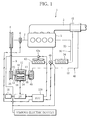
- FIG. 1 schematically illustrates a waste heat utilization system for an internal combustion engine according to the first embodiment of the present invention.
- the waste heat utilization system 1 is mounted on a motor vehicle, for example, and comprises an engine (internal combustion engine) 2, an electric power recovery circuit 10, a cooling water circuit 30, and a Rankine circuit (Rankine cycle) 40.
- the electric power recovery circuit (electric power recovery unit) 10 is an electric circuit which recovers electric power generated by a generator function of a motor-generator 12 and then stores the recovered electric power in a battery (storage battery) 11, and which also detects electric power generated by an expander-side rotor, out of the expander- and output-side rotors of the motor-generator 12, and a charge amount (SOC) of the battery (Rankine output detection unit, battery charge amount (SOC) detection unit). Further, the electric power recovery circuit 10 is capable of switching the function of each of the rotors of the motor-generator 12 between a motor function and a generator function and varying individual motor outputs and individual generator loads (motor-generator output variable unit). The electric power recovered by the electric power recovery circuit 10 is used for driving various electric devices of the vehicle, for example.
- the electric power recovery circuit 10 is connected to an electronic control unit (system control unit) (ECU) 150.
- the ECU 150 calculates a battery demanded electric power amount (battery demanded electric power calculation unit) on the basis of a change, that is, increase or decrease, of the charge amount (SOC), for example, and appropriately controls the degree of recovery of electric power to the battery 11, and the like by switching the function of each rotor of the motor-generator 12 between the motor function and the generator function through the electric power recovery circuit 10 (motor-generator control unit).
- the ECU 150 appropriately controls an electric pump 49 and an electric fan 43a (Rankine cycle electric auxiliary input control unit), which are electrically driven auxiliary machines of the Rankine circuit 40, described later. Accordingly, the electric power recovery circuit 10 can efficiently recover and utilize the electric power generated by the motor-generator 12.
- the motor-generator (motor-generator mechanism) 12 has an inner rotor (one rotor) 16 located inside a stator 14 and an outer rotor (other rotor) 18 located outside the stator 14, as shown in FIG. 1 .
- Rotary shafts 15 and 17 extend in directions opposite to each other and are coupled to the inner and outer rotors 16 and 18, respectively.
- the motor-generator 12 configured as above is capable of causing each of the inner and outer rotors 16 and 18 to function as both a generator and a motor as desired, in accordance with a compound current passed through the stator 14, rotation of the inner rotor 16 by the rotary shaft 15, and rotation of the outer rotor 18 by the rotary shaft 17.
- the structure of the motor-generator 12 is described in detail in, for example, Japanese Laid-open Patent Publication No. 11-275826 , and therefore, description thereof is omitted.
- the cooling water circuit 30 includes a cooling water circulation path 32 communicating with a cooling water passage of the engine 2.
- a cooling water heat exchanger (evaporator) 34, a radiator, not shown, a thermostat, not shown, a water pump, not shown, and the like are inserted in the circulation path 32 in the mentioned order as viewed in the flowing direction of the cooling water, to constitute a closed circuit for cooling the engine 2.
- the Rankine circuit 40 includes a circulation path 42 for a working fluid.
- the cooling water heat exchanger 34, an exhaust gas heat exchanger 41, an expander 48 for generating rotary driving force by expanding the working fluid which has been heated to a superheated state by the cooling water heat exchanger 34 and the exhaust gas heat exchanger 41, a Rankine condenser (condenser) 43, an electric pump (Rankine cycle electrically driven auxiliary machine) 49 and the like are inserted in the circulation path 42 in the mentioned order as viewed in the flowing direction of the working fluid, to constitute a closed circuit.
- the electric pump 49 is connected to the ECU 150.
- the expander 48 is a scroll type expander and has a scroll unit accommodated in a housing thereof.
- the motor-generator 12 and the expander 48 of the Rankine circuit 40 are connected to each other, as shown in FIG. 1 , with the rotary shaft 15 of the motor-generator 12 coaxially rotatably coupled to a rotary shaft 45 of the expander 48.
- An endless belt 9 is passed around a pulley 26 with a rotary shaft 25 and a pulley 8 of a crankshaft 7 of the engine 2, and the rotary shaft 17 of the motor-generator 12 is coupled to the crankshaft 7 of the engine 2 through the rotary shaft (input-output shaft) 25 and the pulley 26 so that the rotary shaft 17 and the crankshaft 7 can rotate synchronously with each other.
- the motor-generator 12, the expander 48 and the rotary shaft 25 constitute a motor-generator device.
- an engagement-disengagement clutch 6 is interposed between the crankshaft 7 of the engine 2 and the pulley 8, as illustrated in FIG. 1 .
- the engagement-disengagement clutch 6 is connected to the ECU 150.
- the Rankine condenser 43 is provided with an electric fan (Rankine cycle electrically driven auxiliary machine) 43a for air-cooling the Rankine condenser 43.
- the electric fan 43a also is connected to the ECU 150.
- the motor-generator 12 can function as both a generator and a motor as needed, in accordance with the compound current passed through the stator 14, the rotation of the inner rotor 16 by the rotary shaft 15, and the rotation of the outer rotor 18 by the rotary shaft 17, as stated above.
- Whether the outer rotor 18 performs the generator function or the motor function depends mainly upon the amount of electric power (Rankine output) generated by the rotation of the motor-generator 12 by the rotary driving force of the expander 48, that is, the amount of electric power generated by the rotation of the inner rotor 16, and the battery demanded electric power calculated by the ECU 15.
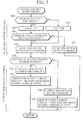
- FIG. 2 is a flowchart illustrating a system control routine for the waste heat utilization system of the first embodiment of the present invention, executed by the ECU 150.
- system control of the waste heat utilization system of the first embodiment as well as control of switchover between the generator function and the motor function of the motor-generator 12, will be explained in detail.
- Step S10 it is determined whether or not the Rankine output is higher than the input to the electric fan 43a plus the input to the electric pump 49, which are electrically driven auxiliary machines.
- Step S12 the control routine proceeds to Step S12 to drive the electric fan 43a and the electric pump 49, and then to Step S18.
- Step S14 the control routine proceeds to Step S14 to stop the electric fan 43a and the electric pump 49, and then to Step S18.
- Step S18 an expander-side rotor generator command is sent to the electric power recovery circuit 10 to alter the characteristics of the compound current passed through the stator 14 such that the inner rotor 16, which is the expander-side rotor, operates as a generator. Specifically, if the inner rotor 16 is functioning as a motor circuit, the electric power recovery circuit 10 switches the electric circuit to a generator circuit. At this time, the load of the motor-generator 12 is controlled so that the rotary driving force of the expander 48 may be optimized. More specifically, the amount of electric current flow is adjusted.
- Step S20 it is determined whether or not the battery demanded electric power calculated by the ECU 15 is higher than electric power corresponding to the aforementioned Rankine output, for example, the amount of electric power generated by the rotation of the inner rotor 16 by the expander 48. If the decision is "True” ("Yes"), the control routine proceeds to Step S22, in which an output-side rotor generator command is sent so that the outer rotor 18, which is the output-side rotor, may be caused to function as a generator.
- the expander 48 when the engine 2 in a cold state is started and is still not warmed up, the expander 48 is unable to generate rotary driving force sufficient to rotate the inner rotor 16, so that no electric power can be generated. If the rotary driving force of the expander 48 is high enough to generate electric power by the inner rotor 16, the battery demanded electric power calculated by the ECU 15 may be higher than the amount of electric power generated by the rotation of the inner rotor 16 by the expander 48, and in this case, the amount of electric power generated by the inner rotor 16 alone is not enough to meet the battery demanded electric power.
- the outer rotor 18 of the motor-generator 12 is rotated by the driving force of the engine 2 transmitted through the rotary shaft 25, to generate electric power, or a deficiency of electric power is made up for by the electric power generated by rotating the outer rotor 18 by the driving force of the engine 2.
- Step S24 an absolute value of the difference between the battery demanded electric power and the electric power corresponding to the Rankine output is set as a generator output target value, and the outer rotor 18 is operated as a generator while altering the characteristics of the compound current passed through the stator 14 such that the output of the outer rotor 18 functioning as a generator becomes equal to the generator output target value. Consequently, the outer rotor 18 can be properly operated as a generator.
- Step S20 determines whether the decision in Step S20 is "False" ("No"), the control routine proceeds to Step S26, in which an output-side rotor motor command is sent to cause the outer rotor 18, which is the output-side rotor, to operate as a motor. If the battery demanded electric power calculated by the ECU 150 is lower than the amount of electric power generated by the rotation of the inner rotor 16 by the expander 48, the battery demanded electric power can be met solely by the amount of electric power generated by the inner rotor 16. Surplus electric power by which the amount of electric power generated by the inner rotor 16 exceeds the battery demanded electric power may be used to rotate the outer roller 18.
- Step S28 an absolute value of the difference between the battery demanded electric power and the electric power corresponding to the Rankine output is set as a motor output target value, and the outer rotor 18 is operated as a motor while altering the characteristics of the compound current passed through the stator 14 such that the output of the outer rotor 18 functioning as a motor becomes equal to the motor output target value.
- the outer rotor 18 can be properly operated as a motor.
- the expander 48 of the Rankine circuit 40 and the motor-generator 12 having the inner and outer rotors 16 and 18 are coupled to each other such that the pulley 8 of the engine 2 and the expander 48 are located serially with the motor-generator 12 in between, and the endless belt 9 is passed around the pulley 8 of the engine 8 and the pulley 26, to cause the motor-generator 12 to function as a generator or a motor in accordance with the Rankine output of the Rankine circuit 40.
- the expander 48 and the rotary shaft 25 can be configured as a compact assembly.
- the motor-generator 12 can be used as an alternator with a deficiency of the rotary driving force of the expander 48 compensated for by the rotary driving force of the engine 2, and depending on the amount of electric power generated by the rotation of the inner rotor 16, the rotational energy of the expander 48 can be readily used to efficiently assist the rotary driving force of the engine 2 with zero waste. For example, even in a situation where the outside air temperature is high as in the summertime, the electric power demanded by the vehicle can be satisfactorily generated by the motor-generator 12.
- the expander 48 is not adversely affected and the pressure of the working fluid on the upstream side of the expander 48 can be kept high, making it possible to assist the driving force of the engine 2 by the rotational energy of the expander 48 through the motor-generator 12.
- FIG. 3 schematically illustrates a waste heat utilization system for an internal combustion engine according to a second embodiment of the present invention.
- the second embodiment differs from the first embodiment in that the pump for circulating the working fluid through the Rankine circuit 40 and the expander are coaxially rotatably coupled to each other.
- the differences between the first and second embodiments will be explained.
- a pump 46 of the Rankine circuit 40 is inserted between the cooling water heat exchanger 34 and the Rankine condenser 43, and the pump 46 and the expander 48 are coaxially rotatably coupled to each other and unified into a fluid machine 44.
- FIG. 4 is a longitudinal sectional view of the fluid machine 44.
- the pump 46 is, for example, a variable displacement pump rotated by a rotary shaft 45 to circulate the working fluid through the circulation path 42.
- the pump 46 is disposed so as to be rotated by the rotary shaft 45.
- the expander 48 is a scroll type expander as in the first embodiment, and has a scroll unit accommodated in a housing 47 thereof.
- the scroll unit is constituted by a fixed scroll 90 and a movable scroll 92 configured to make orbiting motion relative to the fixed scroll 90.
- a boss 94 is formed on a back surface of the movable scroll 92 located opposite the fixed scroll 90, and an eccentric bush 96 is fitted in the boss 94 with a radial bearing 95 therebetween.
- a crankpin 98 is inserted through the eccentric bush 96 and is coupled to a scroll unit-side end portion of the rotary shaft 45 at a location offset from the axis thereof, whereby the movable scroll 92 is allowed to make orbiting motion without rotating about its own axis.
- the scroll unit-side end portion of the rotary shaft 45 and the crankpin 98 are coupled to each other by a one-way clutch 100 which permits rotation of the movable scroll 92 of the expander 48 to be transmitted to the rotary shaft 45 but does not transmit rotation in the reverse direction.
- a one-way clutch 100 which permits rotation of the movable scroll 92 of the expander 48 to be transmitted to the rotary shaft 45 but does not transmit rotation in the reverse direction.
- the working fluid circulates through the circulation path 42 in such a manner that the working fluid leaving the pump 46 flows through the cooling water heat exchanger 34, the exhaust gas heat exchanger 41, the expander 48 and the Rankine condenser 43 and then returns to the pump 46.
- the working fluid is expanded in the expander 48, rotary driving force is generated.
- the pump 46 for circulating the working fluid through the Rankine circuit 40 and the expander 48 are unified into the fluid machine 44.
- the motor-generator device is constituted by the motor-generator 12, the pump 46, the expander 48, and the rotary shaft 25.
- FIG. 5 is a flowchart illustrating a system control routine for the waste heat utilization system according to the second embodiment of the present invention, executed by the ECU 150. Referring to the flowchart, the system control for the waste heat utilization system of the second embodiment, as well as the control of switchover between the generator function and the motor function of the motor-generator 12, will be explained in detail.
- the pump 46 is unified with the expander 48, and accordingly, the electric fan 43a alone is an electrically driven auxiliary machine of the Rankine circuit 40.
- Step S10' it is determined whether or not the Rankine output is higher than the input to the electric fan 43a.
- the electric power detected from the motor-generator 12 via the electric power recovery circuit 10 and corresponding to the Rankine output for example, the amount of electric power generated by the rotation of the inner rotor 16 by the expander 48 with the pump 46 driven, is higher than the input electric power to the electric fan 43a, which is determined on the basis of the information on the vehicle speed, outside air temperature and the like.
- Step S12 If the decision is "True” ("Yes"), the control routine proceeds to Step S12' to drive the electric fan 43a, and then to Step S16. On the other hand, if the decision is "False” ("No"), the control routine proceeds to Step S14' to stop the electric fan 43a, and then to Step S18.
- Step S16 it is determined whether or not the Rankine circuit 40 is capable of self-sustained operation, that is, a pump-side rotor can keep operating with no external input. Specifically, it is determined whether or not the expander 48 is generating rotary driving force and the inner rotor 16, which is the pump-side rotor, is rotating to generate electric power.
- a motor current that the expander 48 contributes by assisting the operation of the inner rotor 16 assumes a value smaller than or equal to a predetermined value (equivalent to the condition that the output current derived from the electric power generation by the inner rotor 16 is greater than or equal to the fixed value) is determined to judge if the Rankine circuit 40 is capable of self-sustained operation or not.
- Step S16 If the decision in Step S16 is "True” ("Yes"), the control routine proceeds to Step S18, in which a pump-side rotor generator command is sent to the electric power recovery circuit 10 to alter the characteristics of the compound current passed through the stator 14 such that the inner rotor 16, which is the pump-side rotor, operates as a generator. Specifically, if the inner rotor 16 is functioning as a motor circuit, the electric power recovery circuit 10 switches the electric circuit to a generator circuit. At this time, the load of the motor-generator 12 is controlled so that the rotary driving force of the expander 48 may be optimized. More specifically, the amount of electric current flow is adjusted.
- Step S16 determines whether the decision in Step S16 is "False" ("No")
- the control routine proceeds to Step S19, in which a pump-side rotor motor command is sent to alter the characteristics of the compound current passed through the stator 14 such that the inner rotor 16, which is the pump-side rotor, operates as a motor.
- the pump 46 is unified with the expander 48, and therefore, if the Rankine circuit 40 is incapable of self-sustained operation, the inner rotor 16 of the motor-generator 12 is made to function as a motor so that the pump 46 may be driven by the motor-generator 12.
- Step S20 it is determined whether or not the battery demanded electric power calculated by the ECU 150 is higher than the electric power corresponding to the aforementioned Rankine output, for example, the amount of electric power generated by the rotation of the inner rotor 16 by the expander 48, as in the first embodiment. If the decision in Step S20 is "True” ("Yes"), the control routine proceeds to Step S22, in which an output-side rotor generator command is sent to alter the characteristics of the compound current passed through the stator 14 so that the outer rotor 18, which is the output-side rotor, may be operated as a generator.
- Step S26 in which an output-side rotor motor command is sent to alter the characteristics of the compound current passed through the stator 14 so that the outer rotor 18, which is the output-side rotor, may be operated as a motor.
- both the electric power generation by the motor-generator 12 and the assisting of the driving force of the engine 2 by the rotational energy of the expander 48 can be efficiently accomplished while saving space, as in the first embodiment.
- the inner rotor 16 can be made to perform the motor function via the stator 14 by using part of the electric power generated by the outer rotor 18.
- the pump 46 of the fluid machine 44 can be forcedly driven by the rotary driving force generated by the inner rotor 16.
- the working fluid can therefore be circulated through the circulation path 42, and the expander 48 can be appropriately supplied with the working fluid to start the Rankine circuit 40.
- the inner rotor 16 can be operated as a motor to drive the pump 46, whereby the Rankine circuit 40 can be started with the working fluid appropriately supplied to the expander 48.
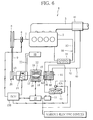
- FIG. 6 schematically illustrates a waste heat utilization system for an internal combustion engine according to the third embodiment of the present invention.
- the third embodiment differs from the second embodiment in that an air conditioning circuit (refrigeration circuit) 20 is additionally provided and that a compression machine (compressor) 24 of the air conditioning circuit 20 is coupled to the motor-generator 12.
- an air conditioning circuit refrigeration circuit
- a compression machine compressor
- the compressor 24 of the air conditioning circuit 20, the motor-generator 12, and the fluid machine 44 which is a unified combination of the pump 46 and the expander 48 of the Rankine circuit 40, are configured such that the rotary shaft 15 of the motor-generator 12 is coaxially rotatably coupled to the rotary shaft 45 of the fluid machine 44 and that the rotary shaft 17 of the motor-generator 12 is coaxially rotatably coupled to a rotary shaft 25 of the compressor 24.
- the endless belt 9 is passed around the pulley 26 of the rotary shaft 25 and the pulley 8 of the crankshaft 7 of the engine 2.
- the air conditioning circuit 20 includes a circulation path 22 for circulating a refrigerant.
- the compression machine (compressor) 24, an air conditioning condenser, not shown, a gas-liquid separator, not shown, an expansion valve, not shown, an evaporator, not shown, and the like are inserted in the circulation path 22 in the mentioned order as viewed in the flowing direction of the refrigerant, to constitute a closed circuit.
- Air in the vehicle compartment is passed through the evaporator to allow heat to be transferred between the air and the refrigerant, for example, so that the interior of the vehicle compartment is air-conditioned.
- the compressor 24 is driven mainly by the rotary driving force of the engine 2 transmitted to the rotary shaft 25 through the endless belt 9 and the pulley 26, to compress the refrigerant, which has been evaporated in the evaporator, into a superheated vapor state.
- the refrigerant discharged from the compressor 24 is condensed into a liquid state by the air conditioning condenser, and the liquid refrigerant is delivered to the gas-liquid separator. Subsequently, the refrigerant is expanded at the expansion valve and delivered to the evaporator.
- FIG. 7 is a longitudinal sectional view of the compressor 24.
- the configuration of the compressor 24 will be explained in more detail.
- the rotary shaft 25 penetrates through the compressor 24, and the pulley 26 is attached to one end of the rotary shaft 25.
- the compressor 24 is a variable capacity type swash plate compressor, and a cylinder block 52, a valve plate 54 and a cylinder head 56 are fastened to one end of a housing 50 in the mentioned order in a gastight manner.
- a crank chamber 58 is defined between the housing 50 and the cylinder block 52.
- the cylinder head 56 has a suction port and a discharge port formed therein, and a suction chamber 60 and a discharge chamber 62 communicating with the suction and discharge ports, respectively, are formed within the cylinder head 56.
- the suction chamber 60 can communicate with each cylinder bore 64 in the cylinder block 52 through a corresponding suction reed valve (not shown), and the discharge chamber 62 can communicate with each cylinder bore 64 through a corresponding discharge reed valve 63.
- the discharge chamber 62 communicates with the crank chamber 58 through a communication passage, and a solenoid valve is inserted in the communication passage.
- the solenoid valve is electrically connected to the ECU 150 and opens and closes under the control of the ECU 150, to intermittently connect the discharge chamber 62 and the crank chamber 58 with each other.
- a piston 66 is inserted into each cylinder bore 64 of the cylinder block 52 from the crank chamber side for reciprocating motion in the corresponding cylinder bore 64.
- Each piston 66 has a tail projecting into the crank chamber 58.
- the rotary shaft 25 extends through the crank chamber 58, the cylinder block 52, the valve plate 54 and the cylinder head 56, and are rotatably supported by the housing 50 and the cylinder block 52 with two radial bearings 27 and 28 therebetween, respectively.
- a lip seal 29 is fitted around the rotary shaft 25 and located closer to the pulley 26 than the radial bearing 27 is.
- a conversion mechanism is provided between the rotary shaft 25 and the respective tails of the pistons 66 for converting rotary motion of the drive shaft 25 to reciprocating motion of the pistons 66.
- the conversion mechanism includes a disc-shaped rotor 70 fixed on the rotary shaft 25, and a thrust bearing 72 is arranged between the rotor 70 and the housing 50.
- a cylindrical swash plate boss 74 is fitted around a portion of the rotary shaft 25 located between the rotor 70 and the cylinder block 52, and is coupled to the rotor 70 by a hinge 76.
- the swash plate boss 74 has a spherically concaved inner peripheral surface and is disposed in sliding contact with a spherical outer peripheral surface of a sleeve 78 slidably fitted around the rotary shaft 25. That is, the swash plate boss 74 is tiltable with respect to the rotary shaft 25 and at the same time is rotatable together with the rotary shaft 25.
- a compression coil spring 79 is disposed around the rotary shaft 25 and between the sleeve 78 and the rotor 70.
- An annular swash plate 80 is securely fitted around the swash plate boss 74 so as to be rotatable together with the swash plate boss 74.
- the swash plate 80 has an outer peripheral portion located in recesses formed in the respective tails of the pistons 66.
- the recess of each tail has a pair of spherical seats spaced from each other in the axial direction of the piston 66, and a pair of semispherical shoes 82 are received in the respective spherical seats and disposed in sliding contact with the outer peripheral portion of the swash plate 80 so as to hold the swash plate 80 from both sides thereof in the thickness direction of the swash plate 80.
- the amount of the refrigerant discharged from the compressor 24 at this time varies depending on the pressure (back pressure) in the crank chamber 58, which pressure increases and decrease as the aforementioned solenoid valve is opened and closed by the ECU 150.
- the swash plate 80 tilts in response to change of equilibrium among compression reaction force acting upon the pistons 66, the back pressure and the urging force of the compression coil spring 79 applied to the swash plate 80, to increase or decrease the stroke length of the individual pistons 66, so that the discharge capacity (compression capacity) for the refrigerant increases or decreases (compression capacity control unit).
- the operation of the compressor 24 can be restricted by raising the back pressure through adjustment of the opening of the solenoid valve to decrease the degree of tilting of the swash plate 80 and thereby lowering the discharge capacity for the refrigerant.
- the compressor 24 of the air conditioning circuit 20, the motor-generator 12 having the inner and outer rotors 16 and 18, and the fluid machine 44, which is a unified combination of the pump 46 and the expander 48 of the Rankine circuit 40, are configured such that the rotary shaft 15 of the motor-generator 12 is coaxially rotatably coupled to the rotary shaft 45 of the fluid machine 44, and that the rotary shaft 17 of the motor-generator 12 is coaxially rotatably coupled to the rotary shaft 25 of the compressor 24.
- the system control routine for the waste heat utilization system illustrated in the flowchart of FIG. 5 can be directly applied to the third embodiment. Accordingly, with the waste heat utilization system according to the third embodiment of the present invention, it is unnecessary to use a separate alternator even though the compressor 24 of the air conditioning circuit 20 is provided, and the compressor 24, the motor-generator 12 and the fluid machine 44 can be configured as a compact assembly, thus saving space.
- the motor-generator 12 can be used as an alternator with a deficiency of the rotary driving force of the expander 48 compensated for by the rotary driving force of the engine 2, and depending on the amount of electric power generated by the rotation of the inner rotor 16, the rotational energy of the expander 48 can be readily used to efficiently assist the rotary driving force of the engine 2 with zero waste.
- both the electric power generation by the motor-generator 12 and the assisting of the driving force of the engine 2 by the rotational energy of the expander 48 can be efficiently accomplished.
- the compressor 24 a variable capacity type swash plate compressor is used, and therefore, when the demand for operation of the air conditioning circuit 20 is low or zero, the compressor 24 can be made not to impose an unnecessary load. Accordingly, the rotary driving force of the engine 2 can be satisfactorily assisted by the rotational energy of the expander 48.
- the compressor 24 is a variable capacity type swash plate compressor and the discharge capacity thereof is variably controlled in accordance with operating conditions of the air conditioning circuit 20.
- the discharge capacity of the compressor 24 may be reduced or set to zero to restrict the operation of the compressor 24 so that the compressor 24 may not constitute an unnecessary load.
- the rotary driving force of the engine 2 can be satisfactorily assisted by the rotational energy of the expander 48.
- the compressor 24 of the air conditioning circuit 20 is used with the fluid machine 44 including the expander 48 unified with the pump 46, as in the second embodiment, but may alternatively be used with the fluid machine not provided with the pump 46 and including the expander 48 only, as in the first embodiment. Also, when idling of the engine 2 is stopped, for example, the engagement-disengagement clutch 6 is disengaged to cut off the transmission of the rotary driving force from the motor-generator 12 to the engine 2 through the compressor 24.
- the compressor 24 By disengaging the engagement-disengagement clutch 6 at the time of idling-stop, it is possible to operate the compressor 24 by driving the motor-generator 12 by the electric power stored in the battery 11 even while the engine 2 is temporarily stopped because of idling stop, so that the air conditioning circuit 20 can be suitably operated.
- the compressor 24 is coupled in series with the motor-generator 12, but the compressor 24 may alternatively be coupled in parallel with the pulley 26 or be driven by the belt 9 in contact therewith in the configurations of FIGS. 1 and 3 , for example.
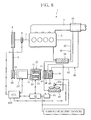
- FIG. 8 schematically illustrates a waste heat utilization system for an internal combustion engine according to the fourth embodiment of the present invention.
- the fourth embodiment differs from the third embodiment in that, instead of the compressor 24 of the air conditioning circuit 20, an auxiliary machine 24' driven by the engine 2 is coupled to the motor-generator 12.
- the system control routine for the waste heat utilization system illustrated in the flowchart of FIG. 5 is directly applied to the fourth embodiment, as in the third embodiment.
- the auxiliary machine 24' driven by the engine 2 is, for example, an oil pump used for power steering but may be some other suitable auxiliary machine. Also in the case where the auxiliary machine 24' driven by the engine 2, in place of the compressor 24 of the air conditioning circuit 20, is coupled to the motor-generator 12, it is possible to accomplish both the electric power generation by the motor-generator 12 and the assisting of the driving force of the engine 2 by the rotational energy of the expander 48 while at the same time saving space, as in the foregoing embodiments.
- the present invention is not limited to the foregoing embodiments and may be modified in various ways without departing from the scope and spirit of the invention.
- the inner rotor 16 of the motor-generator 12 is coupled through the rotary shaft 15 to the expander 48 or the fluid machine 44
- the outer rotor 18 is coupled through the rotary shaft 17 to the pulley 26 or the compressor 24 or the auxiliary machine 24'.
- the inner rotor 16 may be coupled to the pulley 26 or the compressor 24 or the auxiliary machine 24'
- the outer rotor 18 may be coupled to the expander 48 or the fluid machine 44.
- variable capacity type swash plate compressor is used as the compressor 24 of the above embodiment.
- the compressor 24 to be used is not limited to swash plate compressor and some other variable capacity type compressor may be used instead.
- the endless belt 9 is passed around the pulley 8 of the engine 2 and the pulley 26 of the rotary shaft 25 to couple the engine 2 and the rotary shaft 25 to each other.
- a cooling fan, a supercharger, a water pump and the like are provided as additional auxiliary machines of the engine 2
- the endless belt 9 may be passed around pulleys of these auxiliary machines as well.
- the engine 2, the rotary shaft 25 and the auxiliary machines may be coupled by gears or the like, instead of the belt 9.
- the Rankine circuit 40 is configured to recover waste heat of the engine 2 with the use of the cooling water heat exchanger 34 which receives heat from the cooling water circulating through the cooling water circuit 30, and the exhaust gas heat exchanger 41 which receives heat from the exhaust gas flowing through the exhaust pipe 3 of the engine 2. Waste heat of the engine 2 may be recovered using either one of the two heat exchangers.
Abstract
Description
- The present invention relates to a waste heat utilization system for an internal combustion engine and a motor-generator device for use in the system. More particularly, the present invention relates to a waste heat utilization system suited for recovering and utilizing waste heat of an internal combustion engine of a motor vehicle, and a motor-generator device used in the system.
- This type of waste heat utilization system is provided with a Rankine cycle including a circulation path for a refrigerant as a working fluid, in which are sequentially inserted an evaporator for heating and evaporating the working fluid by waste heat of the internal combustion engine, an expander for expanding the highpressure working fluid supplied from the evaporator, to generate rotary driving force, a driving force receiving device to which the rotary driving force generated by the expander is transmitted, a condenser for condensing the working fluid supplied from the expander, and a pump for delivering, to the evaporator, the working fluid supplied from the condenser.
- A fluid machine has been known in which a pump, an expander, and a motor-generator as the driving force receiving device are coaxially arranged, and the motor-generator is caused to function as a motor to rotate the pump when the Rankine cycle is started, and is caused to function as an electric generator after the expander begins to rotate spontaneously because of circulation of the refrigerant (Patent Document 1).
- Patent Document 1: Japanese Laid-open Patent Publication No.
2005-30386 - According to the technique disclosed in
Patent Document 1, the motor-generator is configured to function as a motor for driving the pump and also to function as an electric generator when the expander is operating. However, in a situation where the outside air temperature is high as in the summertime, the condensation temperature rises and the expansion ratio decreases as a result, giving rise to a problem that the turning force of the expander alone is insufficient to cause the motor-generator as the electric generator to generate the electric power demanded by the vehicle. - To secure the electric power demanded by the vehicle, an alternator driven by the internal combustion engine may be separately provided in the vehicle, as in conventional vehicles.
It is not desirable, however, that a single vehicle be provided with two electric generators, namely, a motor-generator and an alternator conventionally used, because the use of the two electric generators requires an extra installation space and leads to increase in weight and cost. - On the other hand, when the amount of air passing through the condenser is large as in the case where the vehicle is traveling at high speeds, the condensation temperature lowers and the expansion ratio increases. In such case, the electric power generated by the motor-generator is not fully used and some of the generated electric power undesirably remains unused.
A waste heat utilization system is conceivable wherein, for example, the internal combustion engine is used as the driving force receiving device, the rotary driving force of the expander is transmitted directly to the internal combustion engine through an endless belt or the like, and the rotary driving force of the expander and of the internal combustion engine is transmitted also to an alternator arranged coaxially with or separately from the expander. - With such configuration, the rotary driving force of the expander can be transmitted to the internal combustion engine, and electric power can be generated using both the rotary driving force of the expander and that of the internal combustion engine by just providing the additional alternator.
However, if the system is configured such that the rotary driving force of the expander is transmitted directly to the internal combustion engine through an endless belt or the like, the internal combustion engine and the expander rotate synchronously with each other. Thus, when the rotating speed of the internal combustion engine is high compared to the rotation of the expander, the internal combustion engine forcedly increases the amount of discharge of the working fluid from the expander, so that the pressure of the working fluid on the upstream side of the expander cannot be kept high, giving rise to a problem that the output of the expander lowers. That is, when the rotating speed of the internal combustion engine is high compared with the rotation of the expander, the rotary driving force of the expander fails to be transmitted to the internal combustion engine or the alternator in a desirable manner, posing a problem of poor efficiency. - The present invention was created in view of the above circumstances, and an object thereof is to provide a waste heat utilization system for an internal combustion engine, which is provided with a Rankine cycle for circulating a working fluid therethrough to enable an expander to generate rotary driving force and in which the driving force of the internal combustion engine can be efficiently assisted by rotational energy of the expander with zero waste and also electric power can be efficiently generated using the rotary driving force of the expander and of the internal combustion engine, and a motor-generator device used in the system.
- To achieve the above object, the present invention provides a waste heat utilization system for an internal combustion engine, comprising: a Rankine cycle including a circulation path for a working fluid, in which are sequentially inserted an evaporator configured to heat and evaporate the working fluid by waste heat of the internal combustion engine, an expander configured to expand the working fluid supplied from the evaporator, to generate rotary driving force, a condenser configured to condense the working fluid supplied from the expander, and a pump configured to deliver, to the evaporator, the working fluid supplied from the condenser; and a motor-generator including an inner rotor and an outer rotor located inside and outside, respectively, of a stator thereof, wherein at least the motor-generator and the expander are coupled to each other with either one of the inner and outer rotors of the motor-generator coupled to a rotary shaft of the expander, and the other of the inner and outer rotors is coupled to a rotary shaft of the internal combustion engine (claim 1).
- Preferably, the other of the inner and outer rotors is coupled to the rotary shaft of the internal combustion engine with an auxiliary machine connected in series or parallel with the other of the inner and outer rotors (claim 2) .
Preferably, the waste heat utilization system further comprises a refrigeration cycle including a circulation path for a refrigerant, in which is inserted a compressor configured to compress the refrigerant by using at least rotary driving force of the internal combustion engine, and the auxiliary machine is the compressor (claim 3). - Preferably, the compressor is a variable capacity type compressor, and the waste heat utilization system further comprises a compression capacity control unit configured to variably control a compression capacity of the variable capacity type compressor in accordance with operating conditions of the refrigeration cycle (claim 4).
Preferably, an engagement-disengagement clutch is arranged between the internal combustion engine and the compressor and configured to establish and cut off transmission of rotary driving force from the motor-generator to the internal combustion engine through the compressor in accordance with an operating state of the internal combustion engine (claim 5). - Preferably, in this case, the expander and the pump are coaxially coupled together into a unified body, the motor-generator and the unified body of the expander and the pump are coupled to each other with the one of the inner and outer rotors coupled to a rotary shaft of the unified body of the expander and the pump, and the other of the inner and outer rotors is coupled to the rotary shaft of the internal combustion engine (claim 6).
- Preferably, the waste heat utilization system further comprises: an electric power recovery unit including a battery configured to store electric power generated by the motor-generator as a result of rotation of the expander or the internal combustion engine; and a system control unit configured to control a degree of recovery of electric power in accordance with a charge amount of the battery (claim 7).
Preferably, the electric power recovery unit includes a Rankine output detection unit configured to detect a Rankine output generated by the Rankine cycle, a battery charge amount detection unit configured to detect the charge amount of the battery, and a motor-generator output variable unit configured to switch a function of each of the inner and outer rotors of the motor-generator between a motor function and a generator function; the system control unit includes a battery demanded electric power calculation unit configured to calculate battery demanded electric power demanded by the electric power recovery unit, and a motor-generator control unit configured to control the motor-generator output variable unit in accordance with the battery demanded electric power calculated by the battery demanded electric power calculation unit; and the system control unit controls the motor-generator control unit in such a manner that the function of the other of the inner and outer rotors is switched to the generator function by the motor-generator output variable unit when the battery demanded electric power calculated by the battery demanded electric power calculation unit is higher than electric power corresponding to the Rankine output detected by the Rankine output detection unit, and is switched to the motor function by the motor-generator output variable unit when the battery demanded electric power is lower than the electric power corresponding to the Rankine output (claim 8) . - Preferably, the motor-generator control unit controls the motor-generator in accordance with a generator output target value when the function of the other of the inner and outer rotors is switched to the generator function, and controls the motor-generator output variable unit in accordance with a motor output target value when the function of the other of the inner and outer rotors is switched to the motor function, and the generator output target value and the motor output target value are each set based on an absolute value of a difference between the battery demanded electric power and the electric power corresponding to the Rankine output (claim 9).
- Preferably, the Rankine cycle includes an electrically driven auxiliary machine, the system control unit further includes a Rankine cycle electric auxiliary input control unit configured to control input electric power to the electrically driven auxiliary machine of the Rankine cycle, and the system control unit causes the Rankine cycle electric auxiliary input control unit to stop operation of the electrically driven auxiliary machine of the Rankine cycle when the electric power corresponding to the Rankine output detected by the Rankine output detection unit is lower at least than the input electric power to the electrically driven auxiliary machine of the Rankine cycle, and causes the Rankine cycle electric auxiliary input control unit to operate the electrically driven auxiliary machine of the Rankine cycle when the electric power corresponding to the Rankine output is higher at least than the input electric power to the electrically driven auxiliary machine of the Rankine cycle (claim 10).
- Preferably, in this case, the expander and the pump are coaxially coupled together into a unified body, the motor-generator and the unified body of the expander and the pump are coupled to each other with the one of the inner and outer rotors coupled to a rotary shaft of the unified body of the expander and the pump, and the other of the inner and outer rotors is coupled to the rotary shaft of the internal combustion engine (claim 11).
- Preferably, the motor-generator control unit controls the motor-generator output variable unit so as to switch the function of the one of the inner and outer rotors to the motor function or the generator function, and the system control unit controls the motor-generator control unit in such a manner that the function of the one of the inner and outer rotors is switched to the generator function by the motor-generator output variable unit when the Rankine output detected by the Rankine output detection unit is higher than or equal to a fixed value, and is switched to the motor function by the motor-generator output variable unit when the Rankine output is lower than the fixed value (claim 12).
- The present invention also provides a motor-generator device for use in a waste heat utilization system for an internal combustion engine, the waste heat utilization system including a Rankine cycle having a circulation path for a working fluid, in which are sequentially inserted an evaporator configured to heat and evaporate the working fluid by waste heat of the internal combustion engine, an expander configured to expand the working fluid supplied from the evaporator, to generate rotary driving force, a condenser configured to condense the working fluid supplied from the expander, and a pump configured to deliver, to the evaporator, the working fluid supplied from the condenser, the motor-generator device comprising: a motor-generator mechanism including an inner rotor and an outer rotor located inside and outside, respectively, of a stator thereof; the expander; and an input-output shaft coupled to a rotary shaft of the internal combustion engine, wherein either one of the inner and outer rotors of the motor-generator mechanism is coupled to a rotary shaft of the expander, and the other of the inner and outer rotors is coupled to the input-output shaft (claim 13) .
- Preferably, in the motor-generator device, the pump of the Rankine cycle is arranged between the motor-generator mechanism and the expander, and the pump has a drive shaft of which one end is coupled to the expander and of which the other end is coupled to the one of the inner and outer rotors (claim 14).
Preferably, in this case, a one-way clutch is interposed between the pump and the expander and configured not to transmit rotary driving force from the pump to the expander but to transmit rotary driving force from the expander to the pump (claim 15). - The waste heat utilization system according to the present invention is provided with the Rankine cycle and the motor-generator having the inner and outer rotors located inside and outside, respectively, of the stator. The motor-generator and the expander of the Rankine cycle are connected to each other with either one of the inner and outer rotors coupled to the rotary shaft of the expander, and the other of the inner and outer rotors is coupled to the rotary shaft of the internal combustion engine (claim 1) .
- Accordingly, the waste heat utilization system can be configured so as to be compact in size to save space, and also since the rotary shafts of the internal combustion engine and expander are coupled to the respective rotors of the motor-generator, the driving force of the internal combustion engine or the turning force of the expander can be converted to electric power. Thus, even in a situation where the outside air temperature is high as in the summertime, the electric power demanded by the vehicle can be satisfactorily generated by the motor-generator. Also, the rotary shaft of the internal combustion engine and the expander are coupled through the motor-generator, and therefore, even if a rotating speed derived from the driving force of the internal combustion engine is higher than that of the expander, the expander is not adversely affected and the pressure of the working fluid on the upstream side of the expander can be kept high, making it possible to assist the driving force of the internal combustion engine by the rotational energy of the expander through the motor-generator.
- With the waste heat utilization system of the present invention, even in cases where an auxiliary machine is coupled to the motor-generator, sufficient electric power can be generated by the motor-generator while saving space, and the driving force of the internal combustion engine can assisted by the rotational energy of the expander through the motor-generator (claim 2).
Also, in the waste heat utilization system of the present invention including the Rankine cycle and the refrigeration cycle, even in cases where the compressor of the refrigeration cycle is coupled to the motor-generator, sufficient electric power can be generated by the motor-generator while at the same time saving space, and the driving force of the internal combustion engine can assisted by the rotational energy of the expander through the motor-generator (claim 3). - In the waste heat utilization system of the present invention, the compressor is a variable capacity type compressor, and the compression capacity of the variable capacity type compressor is variably controlled by the compression capacity control unit in accordance with operating conditions of the refrigeration cycle. Thus, when the demand for operation of the refrigeration cycle is low or zero, the compression capacity can be lowered or reduced to zero so that the compressor may not apply an unnecessary load, and the driving force of the internal combustion engine can assisted by the rotational energy of the expander through the motor-generator (claim 4).
- Also, in the waste heat utilization system of the present invention, the engagement-disengagement clutch is disengaged at the time of idling-stop of the internal combustion engine, for example, to enable the compressor to keep operating by driving the motor-generator by using the electric power stored in the battery, whereby the refrigeration cycle and thus the air conditioner can be continuously operated (claim 5).
Further, in the waste heat utilization system of the present invention, the pump can be driven by using the rotational energy of the expander and also can be driven by the motor function of the motor-generator when the Rankine cycle is started, so that the working fluid can be supplied appropriately to the expander (claim 6). - In the waste heat utilization system of the present invention, the electric power generated by the motor-generator as a result of the rotation of the expander or the internal combustion engine is recovered by the electric power recovery unit and stored in the battery. The degree of recovery of electric power is controlled by the system control unit in accordance with the charge amount of the battery, namely, the battery demanded electric power, and therefore, the electric power generated by the motor-generator can be efficiently recovered and utilized (claim 7).
- In the waste heat utilization system of the present invention, the electric power recovery unit includes the Rankine output detection unit configured to detect the Rankine output generated by the Rankine cycle, the battery charge amount detection unit configured to detect the charge amount of the battery, and the motor-generator output variable unit configured to switch the function of each of the inner and outer rotors of the motor-generator between the motor function and the generator function. The system control unit includes the battery demanded electric power calculation unit configured to calculate the battery demanded electric power demanded by the electric power recovery unit, and the motor-generator control unit configured to control the motor-generator output variable unit in accordance with the battery demanded electric power calculated by the battery demanded electric power calculation unit. The system control unit controls the motor-generator control unit in such a manner that the function of the other of the inner and outer rotors is switched to the generator function by the motor-generator output variable unit when the battery demanded electric power calculated by the battery demanded electric power calculation unit is higher than the electric power corresponding to the Rankine output detected by the Rankine output detection unit, and is switched to the motor function by the motor-generator output variable unit when the battery demanded electric power is lower than the electric power corresponding to the Rankine output. Accordingly, the function of the motor-generator can be efficiently switched between the generator function and the motor function in accordance with the battery demanded electric power and the electric power generated by the motor-generator and corresponding to the Rankine output, for example (claim 8).
- In the waste heat utilization system of the present invention, the generator output target value and the motor output target value are each set based on an absolute value of the difference between the battery demanded electric power and the electric power corresponding to the Rankine output. When the function of the other of the inner and outer rotors is switched to the generator function, the motor-generator is controlled in accordance with the generator output target value, and when the function of the other of the inner and outer rotors is switched to the motor function, the motor-generator is controlled in accordance with the motor output target value. Accordingly, the other of the inner and outer rotors can be properly operated as a generator or a motor (claim 9) .
- In the waste heat utilization system of the present invention, when the electric power corresponding to the Rankine output is lower at least than the input electric power to the Rankine cycle electric auxiliary machine for air-cooling the condenser, operation of the Rankine cycle electric auxiliary machine is stopped, and when the electric power corresponding to the Rankine output is higher at least than the input electric power to the Rankine cycle electric auxiliary machine, the Rankine cycle electric auxiliary machine is operated. It is therefore possible to prevent energy loss in the Rankine cycle (claim 10) .
- Also, in the waste heat utilization system according to the present invention, the system control unit permits the electric power generated by the motor-generator to be efficiently recovered and utilized, and the pump can be driven using the rotational energy of the expander. In addition, the pump can be driven by the motor function of the motor-generator when the Rankine cycle is started. Consequently, the working fluid can be appropriately supplied to the expander (claim 11).
- In the waste heat utilization system of the present invention, when the Rankine output is higher than or equal to the fixed value, the function of the one of the inner and outer rotors is switched to the generator function, and when the Rankine output is lower than the fixed value, the function of the one of the inner and outer rotors is switched to the motor function. Thus, the pump can be made to operate independently with a minimum input, and the working fluid can be appropriately supplied to the expander to start the Rankine cycle (claim 12).
The motor-generator device of the present invention is used in a waste heat utilization system intended for an internal combustion engine and including a Rankine cycle, and comprises: the motor-generator mechanism including the inner and outer rotors located inside and outside, respectively, of the stator; the expander; and the input-output shaft coupled to the rotary shaft of the internal combustion engine, wherein either one of the inner and outer rotors of the motor-generator mechanism is coupled to the rotary shaft of the expander, and the other of the inner and outer rotors is coupled to the input-output shaft (claim 13) . - Accordingly, the motor-generator device can be configured so as to be compact in size to save space, and also since the input-output shaft and the expander are coupled to the respective rotors of the motor-generator mechanism, the driving force of the internal combustion engine or the turning force of the expander can be converted to electric power. Thus, even in a situation where the outside air temperature is high as in the summertime, the electric power demanded by the vehicle can be satisfactorily generated by the motor-generator mechanism. Also, the input-output shaft and the expander are coupled through the motor-generator mechanism, and therefore, even if the rotating speed derived from the driving force of the internal combustion engine is higher than that of the expander, the expander is not adversely affected and the pressure of the working fluid on the upstream side of the expander can be kept high, making it possible to assist the driving force of the internal combustion engine by the rotational energy of the expander through the motor-generator mechanism.
- Also, in the motor-generator device of the present invention, the pump can be driven by using the rotational energy of the expander and also can be driven by the motor function of the motor-generator mechanism when the Rankine cycle is started, so that the working fluid can be supplied appropriately to the expander (claim 14).
Further, in the motor-generator device of the present invention, the expander can be prevented from applying an unnecessary load on the motor-generator mechanism when the pump is driven by the motor function of the motor-generator mechanism (claim 15) . -
-
FIG. 1 is a schematic diagram illustrating a waste heat utilization system for an internal combustion engine according to a first embodiment of the present invention. -
FIG. 2 is a flowchart illustrating a system control routine for the waste heat utilization system according to the first embodiment of the present invention. -
FIG. 3 is a schematic diagram illustrating a waste heat utilization system for an internal combustion engine according to a second embodiment of the present invention. -
FIG. 4 is a longitudinal sectional view of a fluid machine constituted by a pump and an expander unified into one body. -
FIG. 5 is a flowchart illustrating a system control routine for the waste heat utilization system according to the second embodiment of the present invention. -
FIG. 6 is a schematic diagram illustrating a waste heat utilization system for an internal combustion engine according to a third embodiment of the present invention. -
FIG. 7 is a longitudinal sectional view of a compressor. -
FIG. 8 is a schematic diagram illustrating a waste heat utilization system for an internal combustion engine according to a fourth embodiment of the present invention. - Embodiments of the present invention will be described below with reference to the accompanying drawings.
A first embodiment will be described first.
FIG. 1 schematically illustrates a waste heat utilization system for an internal combustion engine according to the first embodiment of the present invention.
The wasteheat utilization system 1 is mounted on a motor vehicle, for example, and comprises an engine (internal combustion engine) 2, an electricpower recovery circuit 10, a coolingwater circuit 30, and a Rankine circuit (Rankine cycle) 40. - The electric power recovery circuit (electric power recovery unit) 10 is an electric circuit which recovers electric power generated by a generator function of a motor-
generator 12 and then stores the recovered electric power in a battery (storage battery) 11, and which also detects electric power generated by an expander-side rotor, out of the expander- and output-side rotors of the motor-generator 12, and a charge amount (SOC) of the battery (Rankine output detection unit, battery charge amount (SOC) detection unit). Further, the electricpower recovery circuit 10 is capable of switching the function of each of the rotors of the motor-generator 12 between a motor function and a generator function and varying individual motor outputs and individual generator loads (motor-generator output variable unit). The electric power recovered by the electricpower recovery circuit 10 is used for driving various electric devices of the vehicle, for example. - The electric
power recovery circuit 10 is connected to an electronic control unit (system control unit) (ECU) 150. TheECU 150 calculates a battery demanded electric power amount (battery demanded electric power calculation unit) on the basis of a change, that is, increase or decrease, of the charge amount (SOC), for example, and appropriately controls the degree of recovery of electric power to thebattery 11, and the like by switching the function of each rotor of the motor-generator 12 between the motor function and the generator function through the electric power recovery circuit 10 (motor-generator control unit). Also, theECU 150 appropriately controls anelectric pump 49 and anelectric fan 43a (Rankine cycle electric auxiliary input control unit), which are electrically driven auxiliary machines of theRankine circuit 40, described later. Accordingly, the electricpower recovery circuit 10 can efficiently recover and utilize the electric power generated by the motor-generator 12. - The motor-generator (motor-generator mechanism) 12 has an inner rotor (one rotor) 16 located inside a
stator 14 and an outer rotor (other rotor) 18 located outside thestator 14, as shown inFIG. 1 .Rotary shafts outer rotors
The motor-generator 12 configured as above is capable of causing each of the inner andouter rotors stator 14, rotation of theinner rotor 16 by therotary shaft 15, and rotation of theouter rotor 18 by therotary shaft 17. The structure of the motor-generator 12 is described in detail in, for example, Japanese Laid-open Patent Publication No.11-275826 - The cooling
water circuit 30 includes a coolingwater circulation path 32 communicating with a cooling water passage of theengine 2. A cooling water heat exchanger (evaporator) 34, a radiator, not shown, a thermostat, not shown, a water pump, not shown, and the like are inserted in thecirculation path 32 in the mentioned order as viewed in the flowing direction of the cooling water, to constitute a closed circuit for cooling theengine 2.
TheRankine circuit 40 includes acirculation path 42 for a working fluid. The coolingwater heat exchanger 34, an exhaustgas heat exchanger 41, anexpander 48 for generating rotary driving force by expanding the working fluid which has been heated to a superheated state by the coolingwater heat exchanger 34 and the exhaustgas heat exchanger 41, a Rankine condenser (condenser) 43, an electric pump (Rankine cycle electrically driven auxiliary machine) 49 and the like are inserted in thecirculation path 42 in the mentioned order as viewed in the flowing direction of the working fluid, to constitute a closed circuit. At the coolingwater heat exchanger 34, heat is transferred from the cooling water circulated through the coolingwater circuit 30 to the working fluid, and at the exhaustgas heat exchanger 41, heat is transferred from the exhaust gas flowing through anexhaust pipe 3 of theengine 1 to the working fluid, thereby recovering waste heat of theengine 2. Theelectric pump 49 is connected to theECU 150. - The
expander 48 is a scroll type expander and has a scroll unit accommodated in a housing thereof.
The motor-generator 12 and theexpander 48 of theRankine circuit 40 are connected to each other, as shown inFIG. 1 , with therotary shaft 15 of the motor-generator 12 coaxially rotatably coupled to arotary shaft 45 of theexpander 48. Anendless belt 9 is passed around apulley 26 with arotary shaft 25 and apulley 8 of acrankshaft 7 of theengine 2, and therotary shaft 17 of the motor-generator 12 is coupled to thecrankshaft 7 of theengine 2 through the rotary shaft (input-output shaft) 25 and thepulley 26 so that therotary shaft 17 and thecrankshaft 7 can rotate synchronously with each other. - The motor-
generator 12, theexpander 48 and therotary shaft 25 constitute a motor-generator device.
Also, an engagement-disengagement clutch 6 is interposed between thecrankshaft 7 of theengine 2 and thepulley 8, as illustrated inFIG. 1 . The engagement-disengagement clutch 6 is connected to theECU 150.
TheRankine condenser 43 is provided with an electric fan (Rankine cycle electrically driven auxiliary machine) 43a for air-cooling theRankine condenser 43. Theelectric fan 43a also is connected to theECU 150. - Operation of the waste heat utilization system of the first embodiment of the present invention, configured as described above, will be now described.
In the waste heat utilization system of the present invention, the motor-generator 12 can function as both a generator and a motor as needed, in accordance with the compound current passed through thestator 14, the rotation of theinner rotor 16 by therotary shaft 15, and the rotation of theouter rotor 18 by therotary shaft 17, as stated above. Whether theouter rotor 18 performs the generator function or the motor function depends mainly upon the amount of electric power (Rankine output) generated by the rotation of the motor-generator 12 by the rotary driving force of theexpander 48, that is, the amount of electric power generated by the rotation of theinner rotor 16, and the battery demanded electric power calculated by theECU 15. -
FIG. 2 is a flowchart illustrating a system control routine for the waste heat utilization system of the first embodiment of the present invention, executed by theECU 150. Referring to the flowchart, system control of the waste heat utilization system of the first embodiment, as well as control of switchover between the generator function and the motor function of the motor-generator 12, will be explained in detail.
In Step S10, it is determined whether or not the Rankine output is higher than the input to theelectric fan 43a plus the input to theelectric pump 49, which are electrically driven auxiliary machines. In practice, it is determined whether or not the generated electric power detected from the motor-generator 12 via the electricpower recovery circuit 10 and corresponding to the Rankine output, for example, the amount of electric power generated by the rotation of theinner rotor 16 by theexpander 48, is higher than the input electric power to theelectric fan 43a plus the input electric power to theelectric pump 49, both determined on the basis of information on vehicle speed, outside air temperature and the like. If the decision is "True" ("Yes"), the control routine proceeds to Step S12 to drive theelectric fan 43a and theelectric pump 49, and then to Step S18. On the other hand, if the decision is "False" ("No"), the control routine proceeds to Step S14 to stop theelectric fan 43a and theelectric pump 49, and then to Step S18. - That is, when the Rankine output is lower than the input to the
electric fan 43a plus the input to theelectric pump 49, the total input to theelectric fan 43a and theelectric pump 49 is higher than the Rankine output in theRankine circuit 40, and since energy loss is being caused, theelectric fan 43a and theelectric pump 49 are stopped. It is therefore possible to prevent energy loss from being caused in theRankine circuit 40. - In Step S18, an expander-side rotor generator command is sent to the electric
power recovery circuit 10 to alter the characteristics of the compound current passed through thestator 14 such that theinner rotor 16, which is the expander-side rotor, operates as a generator. Specifically, if theinner rotor 16 is functioning as a motor circuit, the electricpower recovery circuit 10 switches the electric circuit to a generator circuit. At this time, the load of the motor-generator 12 is controlled so that the rotary driving force of theexpander 48 may be optimized. More specifically, the amount of electric current flow is adjusted. - In Step S20, it is determined whether or not the battery demanded electric power calculated by the
ECU 15 is higher than electric power corresponding to the aforementioned Rankine output, for example, the amount of electric power generated by the rotation of theinner rotor 16 by theexpander 48. If the decision is "True" ("Yes"), the control routine proceeds to Step S22, in which an output-side rotor generator command is sent so that theouter rotor 18, which is the output-side rotor, may be caused to function as a generator. - For example, when the
engine 2 in a cold state is started and is still not warmed up, theexpander 48 is unable to generate rotary driving force sufficient to rotate theinner rotor 16, so that no electric power can be generated. If the rotary driving force of theexpander 48 is high enough to generate electric power by theinner rotor 16, the battery demanded electric power calculated by theECU 15 may be higher than the amount of electric power generated by the rotation of theinner rotor 16 by theexpander 48, and in this case, the amount of electric power generated by theinner rotor 16 alone is not enough to meet the battery demanded electric power. - Accordingly, if, in such a situation, the battery demands electric power and the battery demanded electric power is higher than the amount of electric power generated by the rotation of the
inner rotor 16 by theexpander 48, theouter rotor 18 of the motor-generator 12 is rotated by the driving force of theengine 2 transmitted through therotary shaft 25, to generate electric power, or a deficiency of electric power is made up for by the electric power generated by rotating theouter rotor 18 by the driving force of theengine 2. - Specifically, in Step S24, an absolute value of the difference between the battery demanded electric power and the electric power corresponding to the Rankine output is set as a generator output target value, and the
outer rotor 18 is operated as a generator while altering the characteristics of the compound current passed through thestator 14 such that the output of theouter rotor 18 functioning as a generator becomes equal to the generator output target value. Consequently, theouter rotor 18 can be properly operated as a generator. - On the other hand, if the decision in Step S20 is "False" ("No"), the control routine proceeds to Step S26, in which an output-side rotor motor command is sent to cause the
outer rotor 18, which is the output-side rotor, to operate as a motor.
If the battery demanded electric power calculated by theECU 150 is lower than the amount of electric power generated by the rotation of theinner rotor 16 by theexpander 48, the battery demanded electric power can be met solely by the amount of electric power generated by theinner rotor 16. Surplus electric power by which the amount of electric power generated by theinner rotor 16 exceeds the battery demanded electric power may be used to rotate theouter roller 18. - Thus, when the battery demanded electric power is lower than the electric power corresponding to the Rankine output, for example, when the amount of electric power generated by the rotation of the
inner rotor 16 by theexpander 48 is higher than or equal to the battery demanded electric power, the rotational energy of theexpander 48 is used to assist the rotary driving force of theengine 2.
Specifically, in Step S28, an absolute value of the difference between the battery demanded electric power and the electric power corresponding to the Rankine output is set as a motor output target value, and theouter rotor 18 is operated as a motor while altering the characteristics of the compound current passed through thestator 14 such that the output of theouter rotor 18 functioning as a motor becomes equal to the motor output target value. As a result, theouter rotor 18 can be properly operated as a motor. - As described above, in the waste heat utilization system for an internal combustion engine according to the present invention, the
expander 48 of theRankine circuit 40 and the motor-generator 12 having the inner andouter rotors pulley 8 of theengine 2 and theexpander 48 are located serially with the motor-generator 12 in between, and theendless belt 9 is passed around thepulley 8 of theengine 8 and thepulley 26, to cause the motor-generator 12 to function as a generator or a motor in accordance with the Rankine output of theRankine circuit 40. - Thus, it is unnecessary to use a separate alternator, and the motor-
generator 12, theexpander 48 and the rotary shaft 25 (motor-generator device) can be configured as a compact assembly. Also, the motor-generator 12 can be used as an alternator with a deficiency of the rotary driving force of theexpander 48 compensated for by the rotary driving force of theengine 2, and depending on the amount of electric power generated by the rotation of theinner rotor 16, the rotational energy of theexpander 48 can be readily used to efficiently assist the rotary driving force of theengine 2 with zero waste. For example, even in a situation where the outside air temperature is high as in the summertime, the electric power demanded by the vehicle can be satisfactorily generated by the motor-generator 12. Also, even in cases where the rotating speed derived from the driving force of theengine 2 is higher than that of theexpander 48, theexpander 48 is not adversely affected and the pressure of the working fluid on the upstream side of theexpander 48 can be kept high, making it possible to assist the driving force of theengine 2 by the rotational energy of theexpander 48 through the motor-generator 12. - With the waste heat utilization system of the present invention, both the electric power generation by the motor-
generator 12 and the assisting of the driving force of theengine 2 by the rotational energy of theexpander 48 can be efficiently accomplished while saving space.
A second embodiment will be now described.
FIG. 3 schematically illustrates a waste heat utilization system for an internal combustion engine according to a second embodiment of the present invention. - The second embodiment differs from the first embodiment in that the pump for circulating the working fluid through the
Rankine circuit 40 and the expander are coaxially rotatably coupled to each other. In the following, the differences between the first and second embodiments will be explained.
As illustrated inFIG. 3 , apump 46 of theRankine circuit 40 is inserted between the coolingwater heat exchanger 34 and theRankine condenser 43, and thepump 46 and theexpander 48 are coaxially rotatably coupled to each other and unified into afluid machine 44. -
FIG. 4 is a longitudinal sectional view of thefluid machine 44. In the following, the configuration of thefluid machine 44 will be explained in more detail.
Thepump 46 is, for example, a variable displacement pump rotated by arotary shaft 45 to circulate the working fluid through thecirculation path 42. Thepump 46 is disposed so as to be rotated by therotary shaft 45.
Theexpander 48 is a scroll type expander as in the first embodiment, and has a scroll unit accommodated in ahousing 47 thereof. - The scroll unit is constituted by a fixed
scroll 90 and amovable scroll 92 configured to make orbiting motion relative to the fixedscroll 90.
Aboss 94 is formed on a back surface of themovable scroll 92 located opposite the fixedscroll 90, and aneccentric bush 96 is fitted in theboss 94 with aradial bearing 95 therebetween.
Acrankpin 98 is inserted through theeccentric bush 96 and is coupled to a scroll unit-side end portion of therotary shaft 45 at a location offset from the axis thereof, whereby themovable scroll 92 is allowed to make orbiting motion without rotating about its own axis. - The scroll unit-side end portion of the
rotary shaft 45 and thecrankpin 98 are coupled to each other by a one-way clutch 100 which permits rotation of themovable scroll 92 of theexpander 48 to be transmitted to therotary shaft 45 but does not transmit rotation in the reverse direction. Thus, when the rotating speed of therotary shaft 45 is higher than the orbiting speed of themovable scroll 92, the rotation of therotary shaft 45 is not transmitted to themovable scroll 92, that is, theexpander 48, and only when the orbiting speed of themovable scroll 92 is higher than the rotating speed of therotary shaft 45, rotation is transmitted from themovable scroll 92, that is, theexpander 48, to therotary shaft 45. - In the
Rankine circuit 40, the working fluid circulates through thecirculation path 42 in such a manner that the working fluid leaving thepump 46 flows through the coolingwater heat exchanger 34, the exhaustgas heat exchanger 41, theexpander 48 and theRankine condenser 43 and then returns to thepump 46. When the working fluid is expanded in theexpander 48, rotary driving force is generated.
Thus, in the waste heat utilization system according to the second embodiment, thepump 46 for circulating the working fluid through theRankine circuit 40 and theexpander 48 are unified into thefluid machine 44. - In the second embodiment, the motor-generator device is constituted by the motor-
generator 12, thepump 46, theexpander 48, and therotary shaft 25.
FIG. 5 is a flowchart illustrating a system control routine for the waste heat utilization system according to the second embodiment of the present invention, executed by theECU 150. Referring to the flowchart, the system control for the waste heat utilization system of the second embodiment, as well as the control of switchover between the generator function and the motor function of the motor-generator 12, will be explained in detail. - In the second embodiment, the
pump 46 is unified with theexpander 48, and accordingly, theelectric fan 43a alone is an electrically driven auxiliary machine of theRankine circuit 40. In Step S10', therefore, it is determined whether or not the Rankine output is higher than the input to theelectric fan 43a. In practice, it is determined whether or not the electric power detected from the motor-generator 12 via the electricpower recovery circuit 10 and corresponding to the Rankine output, for example, the amount of electric power generated by the rotation of theinner rotor 16 by theexpander 48 with thepump 46 driven, is higher than the input electric power to theelectric fan 43a, which is determined on the basis of the information on the vehicle speed, outside air temperature and the like. If the decision is "True" ("Yes"), the control routine proceeds to Step S12' to drive theelectric fan 43a, and then to Step S16. On the other hand, if the decision is "False" ("No"), the control routine proceeds to Step S14' to stop theelectric fan 43a, and then to Step S18. - That is, when the Rankine output is lower than the input to the
electric fan 43a, the input to theelectric fan 43a is higher than the Rankine output in theRankine circuit 40, and since energy loss is being caused, theelectric fan 43a is stopped. It is therefore possible to prevent energy loss from being caused in theRankine circuit 40.
Then, in Step S16, it is determined whether or not theRankine circuit 40 is capable of self-sustained operation, that is, a pump-side rotor can keep operating with no external input. Specifically, it is determined whether or not theexpander 48 is generating rotary driving force and theinner rotor 16, which is the pump-side rotor, is rotating to generate electric power. More specifically, when theinner rotor 16 is functioning as a generator, whether or not the output current derived from the electric power generation by theinner rotor 16 assumes a value greater than or equal to a fixed value is determined to judge if theRankine circuit 40 is capable of self-sustained operation or not. On the other hand, when theinner rotor 16 is functioning as a motor, whether or not a motor current that theexpander 48 contributes by assisting the operation of theinner rotor 16 assumes a value smaller than or equal to a predetermined value (equivalent to the condition that the output current derived from the electric power generation by theinner rotor 16 is greater than or equal to the fixed value) is determined to judge if theRankine circuit 40 is capable of self-sustained operation or not. - If the decision in Step S16 is "True" ("Yes"), the control routine proceeds to Step S18, in which a pump-side rotor generator command is sent to the electric
power recovery circuit 10 to alter the characteristics of the compound current passed through thestator 14 such that theinner rotor 16, which is the pump-side rotor, operates as a generator. Specifically, if theinner rotor 16 is functioning as a motor circuit, the electricpower recovery circuit 10 switches the electric circuit to a generator circuit. At this time, the load of the motor-generator 12 is controlled so that the rotary driving force of theexpander 48 may be optimized. More specifically, the amount of electric current flow is adjusted. - On the other hand, if the decision in Step S16 is "False" ("No"), the control routine proceeds to Step S19, in which a pump-side rotor motor command is sent to alter the characteristics of the compound current passed through the
stator 14 such that theinner rotor 16, which is the pump-side rotor, operates as a motor. In the second embodiment, thepump 46 is unified with theexpander 48, and therefore, if theRankine circuit 40 is incapable of self-sustained operation, theinner rotor 16 of the motor-generator 12 is made to function as a motor so that thepump 46 may be driven by the motor-generator 12. - Thus, at the start of the
Rankine circuit 40, thepump 46 can be operated by the motor-generator 12 to circulate the working fluid through thecirculation path 42.
In Step S20, it is determined whether or not the battery demanded electric power calculated by theECU 150 is higher than the electric power corresponding to the aforementioned Rankine output, for example, the amount of electric power generated by the rotation of theinner rotor 16 by theexpander 48, as in the first embodiment. If the decision in Step S20 is "True" ("Yes"), the control routine proceeds to Step S22, in which an output-side rotor generator command is sent to alter the characteristics of the compound current passed through thestator 14 so that theouter rotor 18, which is the output-side rotor, may be operated as a generator. On the other hand, if the decision is "False" ("No"), the control routine proceeds to Step S26, in which an output-side rotor motor command is sent to alter the characteristics of the compound current passed through thestator 14 so that theouter rotor 18, which is the output-side rotor, may be operated as a motor. - As described above, with the waste heat utilization system according to the second embodiment of the present invention in which the
pump 46 is provided in theRankine circuit 40, both the electric power generation by the motor-generator 12 and the assisting of the driving force of theengine 2 by the rotational energy of theexpander 48 can be efficiently accomplished while saving space, as in the first embodiment.
In the motor-generator 12, theinner rotor 16 can be made to perform the motor function via thestator 14 by using part of the electric power generated by theouter rotor 18. Thus, in the second embodiment, thepump 46 of thefluid machine 44 can be forcedly driven by the rotary driving force generated by theinner rotor 16. The working fluid can therefore be circulated through thecirculation path 42, and theexpander 48 can be appropriately supplied with the working fluid to start theRankine circuit 40. For example, when theRankine circuit 40 is to be started, theinner rotor 16 can be operated as a motor to drive thepump 46, whereby theRankine circuit 40 can be started with the working fluid appropriately supplied to theexpander 48. - When the
pump 46 is forcedly operated, theexpander 48 does not constitute an unnecessary load on the motor-generator 12 because the one-way clutch 100 is inserted between therotary shaft 45 and thecrankpin 98 of theexpander 48.
A third embodiment will be now described.
FIG. 6 schematically illustrates a waste heat utilization system for an internal combustion engine according to the third embodiment of the present invention. - The third embodiment differs from the second embodiment in that an air conditioning circuit (refrigeration circuit) 20 is additionally provided and that a compression machine (compressor) 24 of the
air conditioning circuit 20 is coupled to the motor-generator 12. In the following, the differences between the second and third embodiments will be explained.
As illustrated in the figure, thecompressor 24 of theair conditioning circuit 20, the motor-generator 12, and thefluid machine 44, which is a unified combination of thepump 46 and theexpander 48 of theRankine circuit 40, are configured such that therotary shaft 15 of the motor-generator 12 is coaxially rotatably coupled to therotary shaft 45 of thefluid machine 44 and that therotary shaft 17 of the motor-generator 12 is coaxially rotatably coupled to arotary shaft 25 of thecompressor 24. Theendless belt 9 is passed around thepulley 26 of therotary shaft 25 and thepulley 8 of thecrankshaft 7 of theengine 2. - The
air conditioning circuit 20 includes acirculation path 22 for circulating a refrigerant. The compression machine (compressor) 24, an air conditioning condenser, not shown, a gas-liquid separator, not shown, an expansion valve, not shown, an evaporator, not shown, and the like are inserted in thecirculation path 22 in the mentioned order as viewed in the flowing direction of the refrigerant, to constitute a closed circuit. Air in the vehicle compartment is passed through the evaporator to allow heat to be transferred between the air and the refrigerant, for example, so that the interior of the vehicle compartment is air-conditioned.
Thecompressor 24 is driven mainly by the rotary driving force of theengine 2 transmitted to therotary shaft 25 through theendless belt 9 and thepulley 26, to compress the refrigerant, which has been evaporated in the evaporator, into a superheated vapor state. The refrigerant discharged from thecompressor 24 is condensed into a liquid state by the air conditioning condenser, and the liquid refrigerant is delivered to the gas-liquid separator. Subsequently, the refrigerant is expanded at the expansion valve and delivered to the evaporator. -
FIG. 7 is a longitudinal sectional view of thecompressor 24. In the following, the configuration of thecompressor 24 will be explained in more detail.
As illustrated in the figure, therotary shaft 25 penetrates through thecompressor 24, and thepulley 26 is attached to one end of therotary shaft 25.
Thecompressor 24 is a variable capacity type swash plate compressor, and acylinder block 52, avalve plate 54 and acylinder head 56 are fastened to one end of ahousing 50 in the mentioned order in a gastight manner. Acrank chamber 58 is defined between thehousing 50 and thecylinder block 52. - The
cylinder head 56 has a suction port and a discharge port formed therein, and a suction chamber 60 and adischarge chamber 62 communicating with the suction and discharge ports, respectively, are formed within thecylinder head 56.
The suction chamber 60 can communicate with each cylinder bore 64 in thecylinder block 52 through a corresponding suction reed valve (not shown), and thedischarge chamber 62 can communicate with each cylinder bore 64 through a correspondingdischarge reed valve 63. Although not illustrated, thedischarge chamber 62 communicates with thecrank chamber 58 through a communication passage, and a solenoid valve is inserted in the communication passage. The solenoid valve is electrically connected to theECU 150 and opens and closes under the control of theECU 150, to intermittently connect thedischarge chamber 62 and thecrank chamber 58 with each other. - A piston 66 is inserted into each cylinder bore 64 of the
cylinder block 52 from the crank chamber side for reciprocating motion in the corresponding cylinder bore 64. Each piston 66 has a tail projecting into thecrank chamber 58.
On the other hand, therotary shaft 25 extends through thecrank chamber 58, thecylinder block 52, thevalve plate 54 and thecylinder head 56, and are rotatably supported by thehousing 50 and thecylinder block 52 with tworadial bearings lip seal 29 is fitted around therotary shaft 25 and located closer to thepulley 26 than theradial bearing 27 is. - A conversion mechanism is provided between the
rotary shaft 25 and the respective tails of the pistons 66 for converting rotary motion of thedrive shaft 25 to reciprocating motion of the pistons 66.
The conversion mechanism includes a disc-shapedrotor 70 fixed on therotary shaft 25, and athrust bearing 72 is arranged between therotor 70 and thehousing 50.
A cylindricalswash plate boss 74 is fitted around a portion of therotary shaft 25 located between therotor 70 and thecylinder block 52, and is coupled to therotor 70 by ahinge 76. Specifically, theswash plate boss 74 has a spherically concaved inner peripheral surface and is disposed in sliding contact with a spherical outer peripheral surface of asleeve 78 slidably fitted around therotary shaft 25. That is, theswash plate boss 74 is tiltable with respect to therotary shaft 25 and at the same time is rotatable together with therotary shaft 25. A compression coil spring 79 is disposed around therotary shaft 25 and between thesleeve 78 and therotor 70. - An
annular swash plate 80 is securely fitted around theswash plate boss 74 so as to be rotatable together with theswash plate boss 74. Theswash plate 80 has an outer peripheral portion located in recesses formed in the respective tails of the pistons 66. The recess of each tail has a pair of spherical seats spaced from each other in the axial direction of the piston 66, and a pair of semispherical shoes 82 are received in the respective spherical seats and disposed in sliding contact with the outer peripheral portion of theswash plate 80 so as to hold theswash plate 80 from both sides thereof in the thickness direction of theswash plate 80. - Consequently, in the
compressor 24, as therotary shaft 25 rotates, the rotary motion is converted to reciprocating motion of the pistons 66 through the conversion mechanism, namely, therotor 70, thehinge 76, theswash plate boss 74, theswash plate 80, and the shoes 82. As each piston 66 reciprocates, the refrigerant in the suction chamber 60 is drawn in and then compressed in the corresponding cylinder bore 64, and the compressed refrigerant is discharged to thecirculation path 22 through thedischarge reed valve 63 and thedischarge chamber 62. - The amount of the refrigerant discharged from the
compressor 24 at this time varies depending on the pressure (back pressure) in thecrank chamber 58, which pressure increases and decrease as the aforementioned solenoid valve is opened and closed by theECU 150. Specifically, theswash plate 80 tilts in response to change of equilibrium among compression reaction force acting upon the pistons 66, the back pressure and the urging force of the compression coil spring 79 applied to theswash plate 80, to increase or decrease the stroke length of the individual pistons 66, so that the discharge capacity (compression capacity) for the refrigerant increases or decreases (compression capacity control unit). - Thus, when the demand for operation of the
air conditioning circuit 20 is low or zero as in the case where theair conditioning circuit 20 need not be operated or the output of theair conditioning circuit 20 needs to be kept low, the operation of thecompressor 24 can be restricted by raising the back pressure through adjustment of the opening of the solenoid valve to decrease the degree of tilting of theswash plate 80 and thereby lowering the discharge capacity for the refrigerant.
As described above, in the waste heat utilization system according to the third embodiment of the present invention, thecompressor 24 of theair conditioning circuit 20, the motor-generator 12 having the inner andouter rotors fluid machine 44, which is a unified combination of thepump 46 and theexpander 48 of theRankine circuit 40, are configured such that therotary shaft 15 of the motor-generator 12 is coaxially rotatably coupled to therotary shaft 45 of thefluid machine 44, and that therotary shaft 17 of the motor-generator 12 is coaxially rotatably coupled to therotary shaft 25 of thecompressor 24. - As for the system control, the system control routine for the waste heat utilization system illustrated in the flowchart of
FIG. 5 can be directly applied to the third embodiment.
Accordingly, with the waste heat utilization system according to the third embodiment of the present invention, it is unnecessary to use a separate alternator even though thecompressor 24 of theair conditioning circuit 20 is provided, and thecompressor 24, the motor-generator 12 and thefluid machine 44 can be configured as a compact assembly, thus saving space. Also, the motor-generator 12 can be used as an alternator with a deficiency of the rotary driving force of theexpander 48 compensated for by the rotary driving force of theengine 2, and depending on the amount of electric power generated by the rotation of theinner rotor 16, the rotational energy of theexpander 48 can be readily used to efficiently assist the rotary driving force of theengine 2 with zero waste. Thus, both the electric power generation by the motor-generator 12 and the assisting of the driving force of theengine 2 by the rotational energy of theexpander 48 can be efficiently accomplished. - For the
compressor 24, a variable capacity type swash plate compressor is used, and therefore, when the demand for operation of theair conditioning circuit 20 is low or zero, thecompressor 24 can be made not to impose an unnecessary load. Accordingly, the rotary driving force of theengine 2 can be satisfactorily assisted by the rotational energy of theexpander 48.
Specifically, thecompressor 24 is a variable capacity type swash plate compressor and the discharge capacity thereof is variably controlled in accordance with operating conditions of theair conditioning circuit 20. Thus, when the demand for operation of theair conditioning circuit 20 is low or zero, the discharge capacity of thecompressor 24 may be reduced or set to zero to restrict the operation of thecompressor 24 so that thecompressor 24 may not constitute an unnecessary load. As a result, the rotary driving force of theengine 2 can be satisfactorily assisted by the rotational energy of theexpander 48. - In the above embodiment, the
compressor 24 of theair conditioning circuit 20 is used with thefluid machine 44 including theexpander 48 unified with thepump 46, as in the second embodiment, but may alternatively be used with the fluid machine not provided with thepump 46 and including theexpander 48 only, as in the first embodiment.
Also, when idling of theengine 2 is stopped, for example, the engagement-disengagement clutch 6 is disengaged to cut off the transmission of the rotary driving force from the motor-generator 12 to theengine 2 through thecompressor 24. - By disengaging the engagement-
disengagement clutch 6 at the time of idling-stop, it is possible to operate thecompressor 24 by driving the motor-generator 12 by the electric power stored in thebattery 11 even while theengine 2 is temporarily stopped because of idling stop, so that theair conditioning circuit 20 can be suitably operated.
In this embodiment, thecompressor 24 is coupled in series with the motor-generator 12, but thecompressor 24 may alternatively be coupled in parallel with thepulley 26 or be driven by thebelt 9 in contact therewith in the configurations ofFIGS. 1 and3 , for example. Also in this case, by disengaging the engagement-disengagement clutch 6 at the time of idling-stop, for example, it is possible to operate thecompressor 24 by driving the motor-generator 12 by the electric power stored in thebattery 11, whereby theair conditioning circuit 20 can be suitably operated. - A fourth embodiment will be now described.
FIG. 8 schematically illustrates a waste heat utilization system for an internal combustion engine according to the fourth embodiment of the present invention.
The fourth embodiment differs from the third embodiment in that, instead of thecompressor 24 of theair conditioning circuit 20, an auxiliary machine 24' driven by theengine 2 is coupled to the motor-generator 12. For the system control, the system control routine for the waste heat utilization system illustrated in the flowchart ofFIG. 5 is directly applied to the fourth embodiment, as in the third embodiment. - The auxiliary machine 24' driven by the
engine 2 is, for example, an oil pump used for power steering but may be some other suitable auxiliary machine.
Also in the case where the auxiliary machine 24' driven by theengine 2, in place of thecompressor 24 of theair conditioning circuit 20, is coupled to the motor-generator 12, it is possible to accomplish both the electric power generation by the motor-generator 12 and the assisting of the driving force of theengine 2 by the rotational energy of theexpander 48 while at the same time saving space, as in the foregoing embodiments. - While the embodiments of the present invention have been described above, the present invention is not limited to the foregoing embodiments and may be modified in various ways without departing from the scope and spirit of the invention.
For example, in the above embodiments, theinner rotor 16 of the motor-generator 12 is coupled through therotary shaft 15 to theexpander 48 or thefluid machine 44, and theouter rotor 18 is coupled through therotary shaft 17 to thepulley 26 or thecompressor 24 or the auxiliary machine 24'. Conversely, theinner rotor 16 may be coupled to thepulley 26 or thecompressor 24 or the auxiliary machine 24', and theouter rotor 18 may be coupled to theexpander 48 or thefluid machine 44. - Also, a variable capacity type swash plate compressor is used as the
compressor 24 of the above embodiment. Thecompressor 24 to be used is not limited to swash plate compressor and some other variable capacity type compressor may be used instead.
In the foregoing embodiments, theendless belt 9 is passed around thepulley 8 of theengine 2 and thepulley 26 of therotary shaft 25 to couple theengine 2 and therotary shaft 25 to each other. Where a cooling fan, a supercharger, a water pump and the like are provided as additional auxiliary machines of theengine 2, for example, theendless belt 9 may be passed around pulleys of these auxiliary machines as well. Also, theengine 2, therotary shaft 25 and the auxiliary machines may be coupled by gears or the like, instead of thebelt 9. - Further, in the above embodiments, the
Rankine circuit 40 is configured to recover waste heat of theengine 2 with the use of the coolingwater heat exchanger 34 which receives heat from the cooling water circulating through the coolingwater circuit 30, and the exhaustgas heat exchanger 41 which receives heat from the exhaust gas flowing through theexhaust pipe 3 of theengine 2. Waste heat of theengine 2 may be recovered using either one of the two heat exchangers. -
- 1
- waste heat utilization system
- 2
- engine
- 8, 26
- pulley
- 9
- belt
- 10
- electric power recovery circuit
- 12
- motor-generator
- 14
- stator
- 15, 17
- rotary shaft
- 16
- inner rotor (one rotor)
- 18
- outer rotor (other rotor)
- 20
- air conditioning circuit (refrigeration cycle)
- 24
- compressor
- 24'
- auxiliary machine
- 25
- rotary shaft
- 30
- cooling water circuit
- 40
- Rankine circuit (Rankine cycle)
- 43
- Rankine condenser (condenser)
- 43a
- electric fan
- 44
- fluid machine
- 46
- pump
- 45
- rotary shaft
- 48
- expander
- 49
- electric pump
- 150
- ECU
Claims (15)
- A waste heat utilization system for an internal combustion engine, comprising:a Rankine cycle including a circulation path for a working fluid, in which are sequentially inserted an evaporator configured to heat and evaporate the working fluid by waste heat of the internal combustion engine, an expander configured to expand the working fluid supplied from the evaporator, to generate rotary driving force, a condenser configured to condense the working fluid supplied from the expander, and a pump configured to deliver, to the evaporator, the working fluid supplied from the condenser; anda motor-generator including an inner rotor and an outer rotor located inside and outside, respectively, of a stator thereof,wherein at least the motor-generator and the expander are coupled to each other with either one of the inner and outer rotors of the motor-generator coupled to a rotary shaft of the expander, and the other of the inner and outer rotors is coupled to a rotary shaft of the internal combustion engine.
- The waste heat utilization system according to claim 1, wherein the other of the inner and outer rotors is coupled to the rotary shaft of the internal combustion engine with an auxiliary machine connected in series or parallel with the other of the inner and outer rotors.
- The waste heat utilization system according to claim 2, further comprising a refrigeration cycle including a circulation path for a refrigerant, in which is inserted a compressor configured to compress the refrigerant by using at least rotary driving force of the internal combustion engine,
wherein the auxiliary machine is the compressor. - The waste heat utilization system according to claim 3, wherein:the compressor is a variable capacity type compressor, andthe waste heat utilization system further comprises a compression capacity control unit configured to variably control a compression capacity of the variable capacity type compressor in accordance with operating conditions of the refrigeration cycle.
- The waste heat utilization system according to claim 3 or 4, wherein an engagement-disengagement clutch is arranged between the internal combustion engine and the compressor and configured to establish and cut off transmission of rotary driving force from the motor-generator to the internal combustion engine through the compressor in accordance with an operating state of the internal combustion engine.
- The waste heat utilization system according to any one of claims 1 to 5, wherein:the expander and the pump are coaxially coupled together into a unified body, andthe motor-generator and the unified body of the expander and the pump are coupled to each other with the one of the inner and outer rotors coupled to a rotary shaft of the unified body of the expander and the pump, and the other of the inner and outer rotors is coupled to the rotary shaft of the internal combustion engine.
- The waste heat utilization system according to any one of claims 1 to 5, further comprising:an electric power recovery unit including a battery configured to store electric power generated by the motor-generator as a result of rotation of the expander or the internal combustion engine; anda system control unit configured to control a degree of recovery of electric power in accordance with a charge amount of the battery.
- The waste heat utilization system according to claim 7, wherein:the electric power recovery unit includes a Rankine output detection unit configured to detect a Rankine output generated by the Rankine cycle, a battery charge amount detection unit configured to detect the charge amount of the battery, and a motor-generator output variable unit configured to switch a function of each of the inner and outer rotors of the motor-generator between a motor function and a generator function,the system control unit includes a battery demanded electric power calculation unit configured to calculate battery demanded electric power demanded by the electric power recovery unit, and a motor-generator control unit configured to control the motor-generator output variable unit in accordance with the battery demanded electric power calculated by the battery demanded electric power calculation unit, andthe system control unit controls the motor-generator control unit in such a manner that the function of the other of the inner and outer rotors is switched to the generator function by the motor-generator output variable unit when the battery demanded electric power calculated by the battery demanded electric power calculation unit is higher than electric power corresponding to the Rankine output detected by the Rankine output detection unit, and is switched to the motor function by the motor-generator output variable unit when the battery demanded electric power is lower than the electric power corresponding to the Rankine output.
- The waste heat utilization system according to claim 8, wherein:the motor-generator control unit controls the motor-generator in accordance with a generator output target value when the function of the other of the inner and outer rotors is switched to the generator function, and controls the motor-generator output variable unit in accordance with a motor output target value when the function of the other of the inner and outer rotors is switched to the motor function, andthe generator output target value and the motor output target value are each set based on an absolute value of a difference between the battery demanded electric power and the electric power corresponding to the Rankine output.
- The waste heat utilization system according to claim 8 or 9, wherein:the Rankine cycle includes an electrically driven auxiliary machine,the system control unit further includes a Rankine cycle electric auxiliary input control unit configured to control input electric power to the electrically driven auxiliary machine of the Rankine cycle, andthe system control unit causes the Rankine cycle electric auxiliary input control unit to stop operation of the electrically driven auxiliary machine of the Rankine cycle when the electric power corresponding to the Rankine output detected by the Rankine output detection unit is lower at least than the input electric power to the electrically driven auxiliary machine of the Rankine cycle, and causes the Rankine cycle electric auxiliary input control unit to operate the electrically driven auxiliary machine of the Rankine cycle when the electric power corresponding to the Rankine output is higher at least than the input electric power to the electrically driven auxiliary machine of the Rankine cycle.
- The waste heat utilization system according to any one of claims 8 to 10, wherein:the expander and the pump are coaxially coupled together into a unified body, andthe motor-generator and the unified body of the expander and the pump are coupled to each other with the one of the inner and outer rotors coupled to a rotary shaft of the unified body of the expander and the pump, and the other of the inner and outer rotors is coupled to the rotary shaft of the internal combustion engine.
- The waste heat utilization system according to claim 11, wherein:the motor-generator control unit controls the motor-generator output variable unit so as to switch the function of the one of the inner and outer rotors to the motor function or the generator function, andthe system control unit controls the motor-generator control unit in such a manner that the function of the one of the inner and outer rotors is switched to the generator function by the motor-generator output variable unit when the Rankine output detected by the Rankine output detection unit is higher than or equal to a fixed value, and is switched to the motor function by the motor-generator output variable unit when the Rankine output is lower than the fixed value.
- A motor-generator device for use in a waste heat utilization system for an internal combustion engine, the waste heat utilization system including a Rankine cycle having a circulation path for a working fluid, in which are sequentially inserted an evaporator configured to heat and evaporate the working fluid by waste heat of the internal combustion engine, an expander configured to expand the working fluid supplied from the evaporator, to generate rotary driving force, a condenser configured to condense the working fluid supplied from the expander, and a pump configured to deliver, to the evaporator, the working fluid supplied from the condenser, the motor-generator device comprising:a motor-generator mechanism including an inner rotor and an outer rotor located inside and outside, respectively, of a stator thereof;the expander; andan input-output shaft coupled to a rotary shaft of the internal combustion engine,wherein either one of the inner and outer rotors of the motor-generator mechanism is coupled to a rotary shaft of the expander, and the other of the inner and outer rotors is coupled to the input-output shaft.
- The motor-generator device according to claim 13, wherein:the pump of the Rankine cycle is arranged between the motor-generator mechanism and the expander, andthe pump has a drive shaft of which one end is coupled to the expander and of which the other end is coupled to the one of the inner and outer rotors.
- The motor-generator device according to claim 14, wherein a one-way clutch is interposed between the pump and the expander and configured not to transmit rotary driving force from the pump to the expander but to transmit rotary driving force from the expander to the pump.
Applications Claiming Priority (2)
| Application Number | Priority Date | Filing Date | Title |
|---|---|---|---|
| JP2010067989A JP5389710B2 (en) | 2010-03-24 | 2010-03-24 | Waste heat utilization system for internal combustion engine and motor generator device used in the system |
| PCT/JP2011/056756 WO2011118561A1 (en) | 2010-03-24 | 2011-03-22 | System for utilizing waste heat of internal combustion engine, and motor generator device using the system |
Publications (3)
| Publication Number | Publication Date |
|---|---|
| EP2551478A1 true EP2551478A1 (en) | 2013-01-30 |
| EP2551478A4 EP2551478A4 (en) | 2014-06-11 |
| EP2551478B1 EP2551478B1 (en) | 2016-09-21 |
Family
ID=44673113
Family Applications (1)
| Application Number | Title | Priority Date | Filing Date |
|---|---|---|---|
| EP11759366.5A Not-in-force EP2551478B1 (en) | 2010-03-24 | 2011-03-22 | System for utilizing waste heat of internal combustion engine |
Country Status (7)
| Country | Link |
|---|---|
| US (1) | US20130056992A1 (en) |
| EP (1) | EP2551478B1 (en) |
| JP (1) | JP5389710B2 (en) |
| KR (1) | KR20130004339A (en) |
| CN (1) | CN102844528B (en) |
| CA (1) | CA2792543C (en) |
| WO (1) | WO2011118561A1 (en) |
Cited By (3)
| Publication number | Priority date | Publication date | Assignee | Title |
|---|---|---|---|---|
| EP2789811A1 (en) * | 2013-04-08 | 2014-10-15 | FPT Motorenforschung AG | System for heat recovery of a combustion engine |
| WO2015197465A1 (en) * | 2014-06-24 | 2015-12-30 | Mahle International Gmbh | Vehicle |
| EP3303780A4 (en) * | 2015-05-06 | 2019-01-02 | Trienco Ltd. | System and method for dynamic mechanical power management |
Families Citing this family (24)
| Publication number | Priority date | Publication date | Assignee | Title |
|---|---|---|---|---|
| JP5347899B2 (en) * | 2009-10-19 | 2013-11-20 | いすゞ自動車株式会社 | Steam engine for vehicles |
| DE102011013115A1 (en) * | 2011-03-04 | 2012-09-06 | Voith Patent Gmbh | Conveying system for oil and gas |
| JP5804879B2 (en) * | 2011-09-30 | 2015-11-04 | 日産自動車株式会社 | Waste heat utilization equipment |
| JP5708446B2 (en) * | 2011-11-02 | 2015-04-30 | 株式会社豊田自動織機 | Waste heat regeneration system |
| GB2497943A (en) * | 2011-12-22 | 2013-07-03 | Cummins Ltd | Internal combustion engine and waste heat recovery system |
| CN102748895B (en) * | 2012-06-28 | 2014-10-22 | 烟台大学 | Gas heat-pump energy supplying system based on power generation of third working medium |
| US9322300B2 (en) * | 2012-07-24 | 2016-04-26 | Access Energy Llc | Thermal cycle energy and pumping recovery system |
| US20140075941A1 (en) * | 2012-09-14 | 2014-03-20 | Kabushiki Kaisha Kobe Seiko Sho (Kobe Steel, Ltd.) | Power generating apparatus and operation method thereof |
| US10266276B2 (en) * | 2013-03-14 | 2019-04-23 | Textron Innovations, Inc. | Integrated auxiliary power unit, starter-generator-motor, and vapor cycle cooling system for an aircraft |
| US9587546B2 (en) * | 2013-10-02 | 2017-03-07 | Ford Global Technologies, Llc | Methods and systems for hybrid vehicle waste heat recovery |
| WO2015134412A1 (en) * | 2014-03-03 | 2015-09-11 | Eaton Corporation | Coolant energy and exhaust energy recovery system |
| WO2015198656A1 (en) * | 2014-06-25 | 2015-12-30 | 株式会社マリタイムイノベーションジャパン | Heat supply system |
| DE102015204374A1 (en) * | 2015-03-11 | 2016-09-15 | Mahle International Gmbh | axial piston |
| DE102015208859A1 (en) * | 2015-05-13 | 2016-11-17 | Mahle International Gmbh | vehicle |
| KR101766028B1 (en) * | 2015-08-24 | 2017-08-07 | 현대자동차주식회사 | Recovered energy transfer apparatus for waste heat recovery system |
| DE102015219116A1 (en) * | 2015-10-02 | 2017-04-06 | Voith Patent Gmbh | Pump drive train and power plant with a pump drive train |
| JP6314999B2 (en) * | 2016-01-25 | 2018-04-25 | トヨタ自動車株式会社 | Waste heat recovery device control device |
| KR20190021577A (en) | 2017-08-23 | 2019-03-06 | 한화파워시스템 주식회사 | High-efficiency power generation system |
| DE102017223414A1 (en) * | 2017-12-20 | 2019-06-27 | Mahle International Gmbh | heat recovery system |
| CN108457729A (en) * | 2018-01-31 | 2018-08-28 | 中国第汽车股份有限公司 | A kind of engine exhaust energy recycling device and exhaust energy recovery method |
| JP2019143533A (en) * | 2018-02-20 | 2019-08-29 | いすゞ自動車株式会社 | Waste heat utilization device |
| US11001250B2 (en) | 2018-03-01 | 2021-05-11 | Cummins Inc. | Waste heat recovery hybrid power drive |
| US11407283B2 (en) | 2018-04-30 | 2022-08-09 | Tiger Tool International Incorporated | Cab heating systems and methods for vehicles |
| DE102019217031A1 (en) * | 2019-11-05 | 2021-05-06 | Mahle International Gmbh | Method for using waste heat from a heat engine |
Citations (6)
| Publication number | Priority date | Publication date | Assignee | Title |
|---|---|---|---|---|
| WO1997047068A1 (en) * | 1996-06-05 | 1997-12-11 | Sabid Redzic | Differential motor/generator apparatus |
| JPH11275826A (en) * | 1998-03-25 | 1999-10-08 | Nissan Motor Co Ltd | Rotating machine |
| EP1117173A2 (en) * | 2000-01-17 | 2001-07-18 | Nissan Motor Company Limited | Motor/Generator |
| US20040258539A1 (en) * | 2003-06-17 | 2004-12-23 | Denso Corporation | Fluid machine |
| US20060254309A1 (en) * | 2005-05-11 | 2006-11-16 | Denso Corporation | Fluid machine |
| WO2008082388A1 (en) * | 2006-12-28 | 2008-07-10 | Utc Power Corporation | A power split device for a combined heat and power (chp) system |
Family Cites Families (17)
| Publication number | Priority date | Publication date | Assignee | Title |
|---|---|---|---|---|
| DE60027840T2 (en) * | 1999-11-18 | 2006-12-28 | Denso Corp., Kariya | Rotary electric machine for vehicles |
| JP3641243B2 (en) * | 2002-02-26 | 2005-04-20 | 日産自動車株式会社 | Hybrid transmission |
| JP3641265B2 (en) * | 2002-12-04 | 2005-04-20 | 日産自動車株式会社 | Hybrid transmission |
| US7399167B2 (en) * | 2003-01-28 | 2008-07-15 | Denso Corporation | Fluid machine operable in both pump mode and motor mode and waste heat recovering system having the same |
| US7030528B2 (en) * | 2003-02-06 | 2006-04-18 | General Motors Corporation | Dual concentric AC motor |
| US7748226B2 (en) * | 2003-03-25 | 2010-07-06 | Denso Corporation | Waste heat utilizing system |
| JP4014583B2 (en) | 2003-06-20 | 2007-11-28 | 株式会社デンソー | Fluid machinery |
| US7249459B2 (en) * | 2003-06-20 | 2007-07-31 | Denso Corporation | Fluid machine for converting heat energy into mechanical rotational force |
| US7888839B2 (en) * | 2004-03-14 | 2011-02-15 | Revolution Electric Motor Company, Inc. | Commercial low cost, high efficiency motor-generator |
| JP4675717B2 (en) * | 2004-11-19 | 2011-04-27 | 株式会社デンソー | Waste heat utilization device for internal combustion engine and control method thereof |
| DE102005051428B4 (en) * | 2004-10-29 | 2015-05-28 | Denso Corporation | Waste heat recovery device |
| US7690213B2 (en) * | 2006-02-24 | 2010-04-06 | Denso Corporation | Waste heat utilization device and control method thereof |
| JP5299679B2 (en) * | 2009-02-06 | 2013-09-25 | 株式会社デンソー | Motor generator |
| JP5401114B2 (en) * | 2009-02-13 | 2014-01-29 | 日産自動車株式会社 | Vehicle with waste heat recovery device |
| US8231504B2 (en) * | 2009-02-16 | 2012-07-31 | GM Global Technology Operations LLC | Powertrain with dual rotor motor/generator |
| US8330285B2 (en) * | 2009-07-08 | 2012-12-11 | Toyota Motor Engineering & Manufacturing North America, Inc. | Method and system for a more efficient and dynamic waste heat recovery system |
| US8742641B2 (en) * | 2010-11-23 | 2014-06-03 | Remy Technologies, L.L.C. | Concentric motor power generation and drive system |
-
2010
- 2010-03-24 JP JP2010067989A patent/JP5389710B2/en not_active Expired - Fee Related
-
2011
- 2011-03-22 WO PCT/JP2011/056756 patent/WO2011118561A1/en active Application Filing
- 2011-03-22 EP EP11759366.5A patent/EP2551478B1/en not_active Not-in-force
- 2011-03-22 US US13/637,012 patent/US20130056992A1/en not_active Abandoned
- 2011-03-22 CN CN201180015493.0A patent/CN102844528B/en not_active Expired - Fee Related
- 2011-03-22 CA CA2792543A patent/CA2792543C/en not_active Expired - Fee Related
- 2011-03-22 KR KR1020127027052A patent/KR20130004339A/en not_active Application Discontinuation
Patent Citations (6)
| Publication number | Priority date | Publication date | Assignee | Title |
|---|---|---|---|---|
| WO1997047068A1 (en) * | 1996-06-05 | 1997-12-11 | Sabid Redzic | Differential motor/generator apparatus |
| JPH11275826A (en) * | 1998-03-25 | 1999-10-08 | Nissan Motor Co Ltd | Rotating machine |
| EP1117173A2 (en) * | 2000-01-17 | 2001-07-18 | Nissan Motor Company Limited | Motor/Generator |
| US20040258539A1 (en) * | 2003-06-17 | 2004-12-23 | Denso Corporation | Fluid machine |
| US20060254309A1 (en) * | 2005-05-11 | 2006-11-16 | Denso Corporation | Fluid machine |
| WO2008082388A1 (en) * | 2006-12-28 | 2008-07-10 | Utc Power Corporation | A power split device for a combined heat and power (chp) system |
Non-Patent Citations (1)
| Title |
|---|
| See also references of WO2011118561A1 * |
Cited By (3)
| Publication number | Priority date | Publication date | Assignee | Title |
|---|---|---|---|---|
| EP2789811A1 (en) * | 2013-04-08 | 2014-10-15 | FPT Motorenforschung AG | System for heat recovery of a combustion engine |
| WO2015197465A1 (en) * | 2014-06-24 | 2015-12-30 | Mahle International Gmbh | Vehicle |
| EP3303780A4 (en) * | 2015-05-06 | 2019-01-02 | Trienco Ltd. | System and method for dynamic mechanical power management |
Also Published As
| Publication number | Publication date |
|---|---|
| JP5389710B2 (en) | 2014-01-15 |
| CA2792543C (en) | 2014-05-06 |
| CN102844528A (en) | 2012-12-26 |
| WO2011118561A1 (en) | 2011-09-29 |
| JP2011202518A (en) | 2011-10-13 |
| US20130056992A1 (en) | 2013-03-07 |
| EP2551478A4 (en) | 2014-06-11 |
| KR20130004339A (en) | 2013-01-09 |
| EP2551478B1 (en) | 2016-09-21 |
| CN102844528B (en) | 2015-08-26 |
| CA2792543A1 (en) | 2011-09-29 |
Similar Documents
| Publication | Publication Date | Title |
|---|---|---|
| EP2551478B1 (en) | System for utilizing waste heat of internal combustion engine | |
| US7260952B2 (en) | Fluid machine | |
| US7249459B2 (en) | Fluid machine for converting heat energy into mechanical rotational force | |
| US7399167B2 (en) | Fluid machine operable in both pump mode and motor mode and waste heat recovering system having the same | |
| US7181919B2 (en) | System utilizing waste heat of internal combustion engine | |
| US7870733B2 (en) | Fluid machine for rankine cycle | |
| US7418824B2 (en) | Refrigerating apparatus and fluid machine therefor | |
| US7748226B2 (en) | Waste heat utilizing system | |
| US6928820B2 (en) | Waste heat collecting system having rankine cycle and heating cycle | |
| US20070227472A1 (en) | Waste heat collecting system having expansion device | |
| US20060254309A1 (en) | Fluid machine | |
| US20060213218A1 (en) | Fluid pump having expansion device and rankine cycle using the same | |
| US20040231331A1 (en) | Fluid machine | |
| JP5389608B2 (en) | Fluid machinery and waste heat utilization system for automobiles using fluid machinery | |
| JP4606840B2 (en) | Composite fluid machine and refrigeration apparatus using the same | |
| JP4078994B2 (en) | Fluid machinery and waste heat recovery system | |
| JP4079114B2 (en) | Fluid machinery | |
| JP2006342793A (en) | Fluid machine | |
| JP2005313878A (en) | Rankine cycle system and control method for the same | |
| JP2008157152A (en) | Rankine cycle | |
| JP4463660B2 (en) | Refrigeration equipment | |
| JP4711884B2 (en) | Rotation output generator | |
| JP2004324595A (en) | Positive displacement fluid machine | |
| JP4055724B2 (en) | Fluid machinery | |
| JP2008180148A (en) | Fluid machine |
Legal Events
| Date | Code | Title | Description |
|---|---|---|---|
| PUAI | Public reference made under article 153(3) epc to a published international application that has entered the european phase |
Free format text: ORIGINAL CODE: 0009012 |
|
| 17P | Request for examination filed |
Effective date: 20120914 |
|
| AK | Designated contracting states |
Kind code of ref document: A1 Designated state(s): AL AT BE BG CH CY CZ DE DK EE ES FI FR GB GR HR HU IE IS IT LI LT LU LV MC MK MT NL NO PL PT RO RS SE SI SK SM TR |
|
| DAX | Request for extension of the european patent (deleted) | ||
| A4 | Supplementary search report drawn up and despatched |
Effective date: 20140509 |
|
| RIC1 | Information provided on ipc code assigned before grant |
Ipc: H02K 16/02 20060101ALI20140502BHEP Ipc: F01K 23/06 20060101ALI20140502BHEP Ipc: F01D 15/10 20060101ALI20140502BHEP Ipc: F01N 5/02 20060101ALI20140502BHEP Ipc: F01K 23/10 20060101AFI20140502BHEP Ipc: F01K 23/14 20060101ALI20140502BHEP Ipc: F01D 15/08 20060101ALI20140502BHEP Ipc: F02G 5/00 20060101ALI20140502BHEP Ipc: F02G 5/02 20060101ALI20140502BHEP Ipc: F02G 5/04 20060101ALI20140502BHEP |
|
| GRAP | Despatch of communication of intention to grant a patent |
Free format text: ORIGINAL CODE: EPIDOSNIGR1 |
|
| RIC1 | Information provided on ipc code assigned before grant |
Ipc: F01D 15/10 20060101ALI20160311BHEP Ipc: F01K 23/10 20060101AFI20160311BHEP Ipc: F01N 5/02 20060101ALI20160311BHEP Ipc: F01K 23/14 20060101ALI20160311BHEP Ipc: H02K 16/02 20060101ALI20160311BHEP Ipc: F02G 5/04 20060101ALI20160311BHEP Ipc: F02G 5/02 20060101ALI20160311BHEP Ipc: F01K 23/06 20060101ALI20160311BHEP Ipc: F02G 5/00 20060101ALI20160311BHEP Ipc: F01D 15/08 20060101ALI20160311BHEP |
|
| INTG | Intention to grant announced |
Effective date: 20160411 |
|
| RAP1 | Party data changed (applicant data changed or rights of an application transferred) |
Owner name: SANDEN HOLDINGS CORPORATION |
|
| GRAS | Grant fee paid |
Free format text: ORIGINAL CODE: EPIDOSNIGR3 |
|
| GRAA | (expected) grant |
Free format text: ORIGINAL CODE: 0009210 |
|
| AK | Designated contracting states |
Kind code of ref document: B1 Designated state(s): AL AT BE BG CH CY CZ DE DK EE ES FI FR GB GR HR HU IE IS IT LI LT LU LV MC MK MT NL NO PL PT RO RS SE SI SK SM TR |
|
| REG | Reference to a national code |
Ref country code: GB Ref legal event code: FG4D |
|
| REG | Reference to a national code |
Ref country code: CH Ref legal event code: EP |
|
| REG | Reference to a national code |
Ref country code: AT Ref legal event code: REF Ref document number: 831247 Country of ref document: AT Kind code of ref document: T Effective date: 20161015 |
|
| REG | Reference to a national code |
Ref country code: IE Ref legal event code: FG4D |
|
| REG | Reference to a national code |
Ref country code: DE Ref legal event code: R096 Ref document number: 602011030580 Country of ref document: DE |
|
| REG | Reference to a national code |
Ref country code: LT Ref legal event code: MG4D Ref country code: NL Ref legal event code: MP Effective date: 20160921 |
|
| PG25 | Lapsed in a contracting state [announced via postgrant information from national office to epo] |
Ref country code: LT Free format text: LAPSE BECAUSE OF FAILURE TO SUBMIT A TRANSLATION OF THE DESCRIPTION OR TO PAY THE FEE WITHIN THE PRESCRIBED TIME-LIMIT Effective date: 20160921 Ref country code: FI Free format text: LAPSE BECAUSE OF FAILURE TO SUBMIT A TRANSLATION OF THE DESCRIPTION OR TO PAY THE FEE WITHIN THE PRESCRIBED TIME-LIMIT Effective date: 20160921 Ref country code: RS Free format text: LAPSE BECAUSE OF FAILURE TO SUBMIT A TRANSLATION OF THE DESCRIPTION OR TO PAY THE FEE WITHIN THE PRESCRIBED TIME-LIMIT Effective date: 20160921 Ref country code: NO Free format text: LAPSE BECAUSE OF FAILURE TO SUBMIT A TRANSLATION OF THE DESCRIPTION OR TO PAY THE FEE WITHIN THE PRESCRIBED TIME-LIMIT Effective date: 20161221 |
|
| REG | Reference to a national code |
Ref country code: AT Ref legal event code: MK05 Ref document number: 831247 Country of ref document: AT Kind code of ref document: T Effective date: 20160921 |
|
| PG25 | Lapsed in a contracting state [announced via postgrant information from national office to epo] |
Ref country code: LV Free format text: LAPSE BECAUSE OF FAILURE TO SUBMIT A TRANSLATION OF THE DESCRIPTION OR TO PAY THE FEE WITHIN THE PRESCRIBED TIME-LIMIT Effective date: 20160921 Ref country code: GR Free format text: LAPSE BECAUSE OF FAILURE TO SUBMIT A TRANSLATION OF THE DESCRIPTION OR TO PAY THE FEE WITHIN THE PRESCRIBED TIME-LIMIT Effective date: 20161222 Ref country code: SE Free format text: LAPSE BECAUSE OF FAILURE TO SUBMIT A TRANSLATION OF THE DESCRIPTION OR TO PAY THE FEE WITHIN THE PRESCRIBED TIME-LIMIT Effective date: 20160921 Ref country code: NL Free format text: LAPSE BECAUSE OF FAILURE TO SUBMIT A TRANSLATION OF THE DESCRIPTION OR TO PAY THE FEE WITHIN THE PRESCRIBED TIME-LIMIT Effective date: 20160921 |
|
| PG25 | Lapsed in a contracting state [announced via postgrant information from national office to epo] |
Ref country code: RO Free format text: LAPSE BECAUSE OF FAILURE TO SUBMIT A TRANSLATION OF THE DESCRIPTION OR TO PAY THE FEE WITHIN THE PRESCRIBED TIME-LIMIT Effective date: 20160921 Ref country code: EE Free format text: LAPSE BECAUSE OF FAILURE TO SUBMIT A TRANSLATION OF THE DESCRIPTION OR TO PAY THE FEE WITHIN THE PRESCRIBED TIME-LIMIT Effective date: 20160921 |
|
| PG25 | Lapsed in a contracting state [announced via postgrant information from national office to epo] |
Ref country code: SK Free format text: LAPSE BECAUSE OF FAILURE TO SUBMIT A TRANSLATION OF THE DESCRIPTION OR TO PAY THE FEE WITHIN THE PRESCRIBED TIME-LIMIT Effective date: 20160921 Ref country code: PL Free format text: LAPSE BECAUSE OF FAILURE TO SUBMIT A TRANSLATION OF THE DESCRIPTION OR TO PAY THE FEE WITHIN THE PRESCRIBED TIME-LIMIT Effective date: 20160921 Ref country code: AT Free format text: LAPSE BECAUSE OF FAILURE TO SUBMIT A TRANSLATION OF THE DESCRIPTION OR TO PAY THE FEE WITHIN THE PRESCRIBED TIME-LIMIT Effective date: 20160921 Ref country code: BE Free format text: LAPSE BECAUSE OF FAILURE TO SUBMIT A TRANSLATION OF THE DESCRIPTION OR TO PAY THE FEE WITHIN THE PRESCRIBED TIME-LIMIT Effective date: 20160921 Ref country code: BG Free format text: LAPSE BECAUSE OF FAILURE TO SUBMIT A TRANSLATION OF THE DESCRIPTION OR TO PAY THE FEE WITHIN THE PRESCRIBED TIME-LIMIT Effective date: 20161221 Ref country code: PT Free format text: LAPSE BECAUSE OF FAILURE TO SUBMIT A TRANSLATION OF THE DESCRIPTION OR TO PAY THE FEE WITHIN THE PRESCRIBED TIME-LIMIT Effective date: 20170123 Ref country code: ES Free format text: LAPSE BECAUSE OF FAILURE TO SUBMIT A TRANSLATION OF THE DESCRIPTION OR TO PAY THE FEE WITHIN THE PRESCRIBED TIME-LIMIT Effective date: 20160921 Ref country code: IS Free format text: LAPSE BECAUSE OF FAILURE TO SUBMIT A TRANSLATION OF THE DESCRIPTION OR TO PAY THE FEE WITHIN THE PRESCRIBED TIME-LIMIT Effective date: 20170121 Ref country code: SM Free format text: LAPSE BECAUSE OF FAILURE TO SUBMIT A TRANSLATION OF THE DESCRIPTION OR TO PAY THE FEE WITHIN THE PRESCRIBED TIME-LIMIT Effective date: 20160921 Ref country code: CZ Free format text: LAPSE BECAUSE OF FAILURE TO SUBMIT A TRANSLATION OF THE DESCRIPTION OR TO PAY THE FEE WITHIN THE PRESCRIBED TIME-LIMIT Effective date: 20160921 |
|
| REG | Reference to a national code |
Ref country code: DE Ref legal event code: R097 Ref document number: 602011030580 Country of ref document: DE |
|
| PG25 | Lapsed in a contracting state [announced via postgrant information from national office to epo] |
Ref country code: IT Free format text: LAPSE BECAUSE OF FAILURE TO SUBMIT A TRANSLATION OF THE DESCRIPTION OR TO PAY THE FEE WITHIN THE PRESCRIBED TIME-LIMIT Effective date: 20160921 |
|
| PLBE | No opposition filed within time limit |
Free format text: ORIGINAL CODE: 0009261 |
|
| STAA | Information on the status of an ep patent application or granted ep patent |
Free format text: STATUS: NO OPPOSITION FILED WITHIN TIME LIMIT |
|
| PG25 | Lapsed in a contracting state [announced via postgrant information from national office to epo] |
Ref country code: DK Free format text: LAPSE BECAUSE OF FAILURE TO SUBMIT A TRANSLATION OF THE DESCRIPTION OR TO PAY THE FEE WITHIN THE PRESCRIBED TIME-LIMIT Effective date: 20160921 |
|
| 26N | No opposition filed |
Effective date: 20170622 |
|
| REG | Reference to a national code |
Ref country code: DE Ref legal event code: R119 Ref document number: 602011030580 Country of ref document: DE |
|
| REG | Reference to a national code |
Ref country code: CH Ref legal event code: PL |
|
| GBPC | Gb: european patent ceased through non-payment of renewal fee |
Effective date: 20170322 |
|
| PG25 | Lapsed in a contracting state [announced via postgrant information from national office to epo] |
Ref country code: MC Free format text: LAPSE BECAUSE OF FAILURE TO SUBMIT A TRANSLATION OF THE DESCRIPTION OR TO PAY THE FEE WITHIN THE PRESCRIBED TIME-LIMIT Effective date: 20160921 Ref country code: SI Free format text: LAPSE BECAUSE OF FAILURE TO SUBMIT A TRANSLATION OF THE DESCRIPTION OR TO PAY THE FEE WITHIN THE PRESCRIBED TIME-LIMIT Effective date: 20160921 |
|
| REG | Reference to a national code |
Ref country code: IE Ref legal event code: MM4A |
|
| REG | Reference to a national code |
Ref country code: FR Ref legal event code: ST Effective date: 20171130 |
|
| PG25 | Lapsed in a contracting state [announced via postgrant information from national office to epo] |
Ref country code: FR Free format text: LAPSE BECAUSE OF NON-PAYMENT OF DUE FEES Effective date: 20170331 Ref country code: LU Free format text: LAPSE BECAUSE OF NON-PAYMENT OF DUE FEES Effective date: 20170322 Ref country code: DE Free format text: LAPSE BECAUSE OF NON-PAYMENT OF DUE FEES Effective date: 20171003 |
|
| PG25 | Lapsed in a contracting state [announced via postgrant information from national office to epo] |
Ref country code: CH Free format text: LAPSE BECAUSE OF NON-PAYMENT OF DUE FEES Effective date: 20170331 Ref country code: IE Free format text: LAPSE BECAUSE OF NON-PAYMENT OF DUE FEES Effective date: 20170322 Ref country code: LI Free format text: LAPSE BECAUSE OF NON-PAYMENT OF DUE FEES Effective date: 20170331 Ref country code: GB Free format text: LAPSE BECAUSE OF NON-PAYMENT OF DUE FEES Effective date: 20170322 |
|
| PG25 | Lapsed in a contracting state [announced via postgrant information from national office to epo] |
Ref country code: MT Free format text: LAPSE BECAUSE OF NON-PAYMENT OF DUE FEES Effective date: 20170322 |
|
| PG25 | Lapsed in a contracting state [announced via postgrant information from national office to epo] |
Ref country code: AL Free format text: LAPSE BECAUSE OF FAILURE TO SUBMIT A TRANSLATION OF THE DESCRIPTION OR TO PAY THE FEE WITHIN THE PRESCRIBED TIME-LIMIT Effective date: 20160921 |
|
| PG25 | Lapsed in a contracting state [announced via postgrant information from national office to epo] |
Ref country code: HU Free format text: LAPSE BECAUSE OF FAILURE TO SUBMIT A TRANSLATION OF THE DESCRIPTION OR TO PAY THE FEE WITHIN THE PRESCRIBED TIME-LIMIT; INVALID AB INITIO Effective date: 20110322 |
|
| PG25 | Lapsed in a contracting state [announced via postgrant information from national office to epo] |
Ref country code: CY Free format text: LAPSE BECAUSE OF NON-PAYMENT OF DUE FEES Effective date: 20160921 |
|
| PG25 | Lapsed in a contracting state [announced via postgrant information from national office to epo] |
Ref country code: MK Free format text: LAPSE BECAUSE OF FAILURE TO SUBMIT A TRANSLATION OF THE DESCRIPTION OR TO PAY THE FEE WITHIN THE PRESCRIBED TIME-LIMIT Effective date: 20160921 |
|
| PG25 | Lapsed in a contracting state [announced via postgrant information from national office to epo] |
Ref country code: TR Free format text: LAPSE BECAUSE OF FAILURE TO SUBMIT A TRANSLATION OF THE DESCRIPTION OR TO PAY THE FEE WITHIN THE PRESCRIBED TIME-LIMIT Effective date: 20160921 |
|
| PG25 | Lapsed in a contracting state [announced via postgrant information from national office to epo] |
Ref country code: HR Free format text: LAPSE BECAUSE OF FAILURE TO SUBMIT A TRANSLATION OF THE DESCRIPTION OR TO PAY THE FEE WITHIN THE PRESCRIBED TIME-LIMIT Effective date: 20160921 |