EP2550949A1 - Gentle skin treatment device - Google Patents
Gentle skin treatment device Download PDFInfo
- Publication number
- EP2550949A1 EP2550949A1 EP11006051A EP11006051A EP2550949A1 EP 2550949 A1 EP2550949 A1 EP 2550949A1 EP 11006051 A EP11006051 A EP 11006051A EP 11006051 A EP11006051 A EP 11006051A EP 2550949 A1 EP2550949 A1 EP 2550949A1
- Authority
- EP
- European Patent Office
- Prior art keywords
- axis
- skin treatment
- attachment
- treatment device
- drive
- Prior art date
- Legal status (The legal status is an assumption and is not a legal conclusion. Google has not performed a legal analysis and makes no representation as to the accuracy of the status listed.)
- Granted
Links
- 230000033001 locomotion Effects 0.000 claims description 7
- 230000010355 oscillation Effects 0.000 claims description 5
- 230000005540 biological transmission Effects 0.000 claims description 4
- 230000001815 facial effect Effects 0.000 description 6
- 238000010276 construction Methods 0.000 description 5
- 239000002537 cosmetic Substances 0.000 description 4
- 230000009286 beneficial effect Effects 0.000 description 2
- 210000004209 hair Anatomy 0.000 description 2
- 238000005299 abrasion Methods 0.000 description 1
- 239000003795 chemical substances by application Substances 0.000 description 1
- 238000004140 cleaning Methods 0.000 description 1
- 230000000694 effects Effects 0.000 description 1
- 210000003041 ligament Anatomy 0.000 description 1
- 239000000463 material Substances 0.000 description 1
- 230000003020 moisturizing effect Effects 0.000 description 1
- 210000001331 nose Anatomy 0.000 description 1
- 230000036642 wellbeing Effects 0.000 description 1
Images


Classifications
-
- A—HUMAN NECESSITIES
- A61—MEDICAL OR VETERINARY SCIENCE; HYGIENE
- A61H—PHYSICAL THERAPY APPARATUS, e.g. DEVICES FOR LOCATING OR STIMULATING REFLEX POINTS IN THE BODY; ARTIFICIAL RESPIRATION; MASSAGE; BATHING DEVICES FOR SPECIAL THERAPEUTIC OR HYGIENIC PURPOSES OR SPECIFIC PARTS OF THE BODY
- A61H7/00—Devices for suction-kneading massage; Devices for massaging the skin by rubbing or brushing not otherwise provided for
- A61H7/002—Devices for suction-kneading massage; Devices for massaging the skin by rubbing or brushing not otherwise provided for by rubbing or brushing
- A61H7/004—Devices for suction-kneading massage; Devices for massaging the skin by rubbing or brushing not otherwise provided for by rubbing or brushing power-driven, e.g. electrical
- A61H7/005—Devices for suction-kneading massage; Devices for massaging the skin by rubbing or brushing not otherwise provided for by rubbing or brushing power-driven, e.g. electrical hand-held
-
- A—HUMAN NECESSITIES
- A61—MEDICAL OR VETERINARY SCIENCE; HYGIENE
- A61H—PHYSICAL THERAPY APPARATUS, e.g. DEVICES FOR LOCATING OR STIMULATING REFLEX POINTS IN THE BODY; ARTIFICIAL RESPIRATION; MASSAGE; BATHING DEVICES FOR SPECIAL THERAPEUTIC OR HYGIENIC PURPOSES OR SPECIFIC PARTS OF THE BODY
- A61H23/00—Percussion or vibration massage, e.g. using supersonic vibration; Suction-vibration massage; Massage with moving diaphragms
- A61H23/02—Percussion or vibration massage, e.g. using supersonic vibration; Suction-vibration massage; Massage with moving diaphragms with electric or magnetic drive
- A61H23/0254—Percussion or vibration massage, e.g. using supersonic vibration; Suction-vibration massage; Massage with moving diaphragms with electric or magnetic drive with rotary motor
-
- A—HUMAN NECESSITIES
- A46—BRUSHWARE
- A46B—BRUSHES
- A46B13/00—Brushes with driven brush bodies or carriers
- A46B13/02—Brushes with driven brush bodies or carriers power-driven carriers
-
- A—HUMAN NECESSITIES
- A46—BRUSHWARE
- A46B—BRUSHES
- A46B2200/00—Brushes characterized by their functions, uses or applications
- A46B2200/10—For human or animal care
- A46B2200/102—Brush specifically designed for massaging the skin or scalp
-
- A—HUMAN NECESSITIES
- A61—MEDICAL OR VETERINARY SCIENCE; HYGIENE
- A61H—PHYSICAL THERAPY APPARATUS, e.g. DEVICES FOR LOCATING OR STIMULATING REFLEX POINTS IN THE BODY; ARTIFICIAL RESPIRATION; MASSAGE; BATHING DEVICES FOR SPECIAL THERAPEUTIC OR HYGIENIC PURPOSES OR SPECIFIC PARTS OF THE BODY
- A61H2201/00—Characteristics of apparatus not provided for in the preceding codes
- A61H2201/01—Constructive details
- A61H2201/0173—Means for preventing injuries
- A61H2201/018—By limiting the applied torque or force
-
- A—HUMAN NECESSITIES
- A61—MEDICAL OR VETERINARY SCIENCE; HYGIENE
- A61H—PHYSICAL THERAPY APPARATUS, e.g. DEVICES FOR LOCATING OR STIMULATING REFLEX POINTS IN THE BODY; ARTIFICIAL RESPIRATION; MASSAGE; BATHING DEVICES FOR SPECIAL THERAPEUTIC OR HYGIENIC PURPOSES OR SPECIFIC PARTS OF THE BODY
- A61H2201/00—Characteristics of apparatus not provided for in the preceding codes
- A61H2201/16—Physical interface with patient
- A61H2201/1683—Surface of interface
- A61H2201/1685—Surface of interface interchangeable
Definitions
- the present invention concerns a skin treatment device for professional and private use.
- the device is used for achieving cosmetic or well-being benefits, for example it can be used to have a massage effect or for cleansing and refreshing the skin or for applying a cosmetic composition.
- U.S. patent 2,714,788 discloses a device for removing hair which comprises an electric motor, a holder for an abrasive pad and an abrasive pad. This device is ment to remove hairs from the skin of, for example, the legs by means of abrasion.
- EP 1 429 670 A2 discloses an ultrasonic cleaner comprising a handle and a brush positioned at the proximal end off the handle.
- the cleaner further comprises an ultrasonic vibrator operably attached to the brush.
- a battery positioned within the hollow interior of the handle provides power to the ultrasonic vibrator. Ultrasonic vibration is transmitted from the vibrator through the brush and to its bristles. The cleaner can hence be used for skin cleaning.
- WO 2010/100527 A1 discloses an appliance for facial care.
- the facial appliance comprises a tubular body and axially extending from the tubular body a so-called facial puck.
- This facial puck comprises a facial implement rotatable about a shaft and a sub assembly linked to the shaft.
- This sub assembly includes a spinner journaled for rotation about an axis extending from the tubular body.
- the spinner comprises opposing, radially extending, resiliently biased release fingers. These release fingers removably mount the applicator implement (e.g. the facial implement) for rotation with the spinner.
- the spinner is mounted to the main gear by slip bearings.
- the skin treatment device should be suitable for use with one or several implements, the gentle use should be intuitive and it should be safe. Further the skin treatment device should be protected against accidental harm from improper usage.
- the present invention concerns a skin treatment device for professional and private use.
- a skin treatment device comprising a drive unit and an attachment, the attachment being rotatable about a central support axis, the drive unit providing an off center drive axis, the attachment comprising a skin treatment element and a rotary support element for the skin treatment element, the rotary support element comprising an eccentric, wherein the central support axis is not a driven axis.
- Fig. 1 shows a skin treatment device 10 with its essential elements according to the present invention.
- the device 10 comprises a drive unit 20.
- the drive unit will comprise a motor which will typically provide a rotational or vibrational movement to some output device.
- the motor will typically be an electrical motor which can be battery operated, preferably by a rechargable battery.
- the drive unit 20 will comprise a switch 22, for turning the unit on or off and/or making other selections of an operation mode.
- An attachment 30 can be connected to the drive unit 20.
- a variety of suitable connectors are well-known, often a positive fitting is useful.
- Other attachments can be connected to the drive unit, for example attachment 30 can serve as a first attachment, and a further attachment can serve as a second attachment, which can also be connected to the same drive unit 20.
- the attachment 30 as shown comprises a brush 32.
- the term brush is used herein broadly, to denote an implement, which can comprise conventional bristles of a variety of materials, as known from other areas.
- the brush can also comprise rubber implements, which could have bristle form or which could also have the form of bars or ligaments.
- the brush 32 will typically have a circular outer shape, but could also have other shapes.
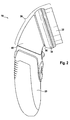
- Fig. 2 shows the same device 20 in a side view. From the side view it is clear that the main axis of the drive unit and the rotational axis of the brush 32 are tilted towards each other. An angle of these axes of somewhat above 90° has been found useful. Angles in the range of 90° to 135° and 100° to 120° have generally been found useful for convenient and effective handling.
- the attachment 30 comprises a gear box 60, onto which the brush 32 with the brush chassis 34 is mounted.
- the gear box 60 is connected to the brush chassis 34 via a rotary support element 50, which is only visible in this view as a ring like structure connection brush chassis 34 to gear box 60.
- Fig. 3 shows a partially cutaway side view of the skin treatment device 10.
- Power from the drive unit 20 is transmitted to the (incoming) drive shaft 62.
- the distal end of the drive shaft is held by a bearing 64.
- a sprocket 66 is mounted onto the drive shaft 62 .
- a crown gear wheel 68 is provided on a drive axis 70. This axis is tilted at an angle of about 110° relative to drive shaft 62.
- an angular gear is provided which serves as a two stage speed reduction unit.
- the speed reduction can be by a factor of more than 2 or more than 3 or 4 or 5. It is also apparant that this robust construction easily fits into the outer shape of the gear box 60.
- the drive axis 70 is parallel (as seen in this side view) to a central support axis 72.
- the central support axis 72 is not a driven axis.
- the central support axis 72 provides rotary support for the rotary support element 50.
- the rotary support element 50 has one degree of freedom, which is the freedom to move about the support axis 72.
- the rotary support element 50 comprises a rotary plate 52 onto which latches 54 are mounted.
- the latches 54 are spring loaded by spring elements 56.
- a support plate 58 is mounted onto rotary plate 52.
- the support plate 58 provides support to a skin treatment element (not shown).
- a rotary oscillation movement can be provided to the rotary support element 50. This movement is transmitted by drive axis 70.
- the drive axis carries an eccentric 74.
- This eccentric 74 comprises an eccentric wheel 76, which carries an eccentric pin 78.
- the pin 78 can then cooperate with a slot (not shown here) in the rotary plate 52.
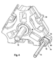
- Fig. 4 provides an enlarged perspective view of the rotary plate 52.
- the rotary plate 52 carries latches 54, which can engage with elements, typically with recesses in the attachment 30, particularly in the chassis 34 of the attachment 30.
- the rotary support element 52 is supported by central axis 72. This central axis provides all of the required mechanical support for element 52, and leaves it one remaining degree of freedom for rotating about the axis 72.
- the rotary plate 52 comprises a slot 80. This slot is shown here as an integral part of the rotary plate 52, but could also be a separate connected or attached element.
- the slot 80 cooperates with pin 78 of eccentric wheel 76. In this way, an eccentric 74 is formed.
- the attachment 30 can comprise a skin treatment implement or element, for example in the form of a brush and can comprise an output element.
- the output element for example in the form of a gear box, can also be part of the drive unit.
- a further gear box or a force transmission element can be comprised by the drive unit.
- the attachment 30 also comprises a rotary support element 50.
- the rotary support element 50 can have a variety of useful forms, and should be linked to the drive unit as to impart a rotation to the skin treatment element.
- the rotary support element 50 can for example have a planar surface perpendicular to the rotating axis, which can support the skin treatment element.
- the attachment 30 is rotatable about a central support axis 72.
- the rotary support element 50 will be rotatable about the same central support axis 72.
- the rotary support element 50 comprises an eccentric 74.
- the central support axis 72 is not a driven axis. In other words, no motor force is transmitted to the central support axis 72.
- the eccentric 74 can be used to impart a motion to the rotary support element 50 and horrtively to a skin treatment implement.
- the eccentric 74 can be provided in a variety of forms. It is comprised by the rotary support element 50 in the sense that it is mechanically linked to the rotary support element 50.
- eccentric 74 is preferably rotated by a drive axis 70.
- the drive axis is positioned in a certain distance from the center (and thereby the central support axis). This distance considerably reduces the chances that the drive axis is damaged by rotational forces induced on the skin treatment implement. Some users may for example try to manually turn the skin treatment implement, which could at least harm a less robust mechanical construction.
- the rotary support element 50 supports a skin treatment element 32.
- the skin treatment element 32 can, for example, be provided in the form of the brush.
- the skin treatment element 32 will have a certain outer contour.
- this outer contour can be circular.
- the outer contour can also be of a different shape, for example be polyangular.
- the representative diameter is relevant in the framework of this invention.
- the standard diameter will be considered here in the representative diameter.
- a representative diameter would be to be determined by measuring average radii from the rotational centre of such a contour.
- a large representative diameter will give raise to considerable rotational forces in a tangential direction. Due to its sturdy construction, the central support axis 72 will not be harmed by such forces, also if they are not exactly tangential. Such forces, however, could harm the drive unit 20 or mechanical parts for transmission of forces from the drive unit to the skin treatment implement 32. To prevent such harm, it is useful to choose a position of the drive axis 70 which is sufficently remote from the central support axis 72.
- the forces acting on the drive axis 70 will then be lower than the forces which are exerted closer to the central axis. Therefore, it is useful to ensure that the distance of the central support axis 72 from the drive axis 70 is more than 20 or 30 or 40 or 50 or 60 percent of the representative diameter of the outer contour of the skin treatment element 32.
- the angle of rotation of such an oscillation is ⁇ 30° or ⁇ 20° or ⁇ 10° or ⁇ 5° or less.
- the mechanical set-up of the device makes it easy to reach a preferred angle of rotation.
- the distance of the drive axis 70 from the central support axis 72 influences the angle of rotation (a large distance leading to a small angle).
- attachment 30 for the skin treatment device such that it can be easily connected to the drive unit and removed therefrom.
- an attachment 30 has been found useful which comprises a drive shaft fot the transmission of a rotary movement from the drive unit to the drive axis and wherein the drive shaft 62 is linked to a sprocket 66 and wherein the sprocket 66 engages with a crown gear wheel 68 and the crown gear wheel 68 is linked to the drive axis 70.
- the drive shaft 62 turns about a first axis and the drive axis turns about a second axis of rotation.
- the first and the second axis in combination can define a certain spacial direction by defining the orientation of a series of planes.
- the mechanical arrangement of off-set axis makes the construction compact and at the same time robust.
- a compact and easy to use device can be designed, by choosing an optimised angle between the first axis and the second axis.
- the angle between the first axis and the second axis can usefully be from 90° to 160°, preferably 100° to 135°.
- the drive shaft 62 comprises a connector for connection with the drive unit.
- the connector can take any standard form, for example the drive unit may have a form of male connector and the drive shaft may have a form of a female connector.
- a single bearing 64 which can be part of the attachment 30, at the end of the drive shaft 62 opposing the connector.
- the single bearing gives the other end of the drive shaft a certain freedom of movement, and this freedom makes it easier to connect the connector of the drive shaft to a matching connector of the drive unit. Hence, it is useful to have the drive shaft not supported by any further bearings.
- the rotary support element 50 can further have some protrusions.
- the protrusions can have a variety of suitable forms, for example they can be of a rounded or a squared form, the protrusions for example can take the form of noses or pyramides or the like. Protrusions of triangular cross-sections have been found useful.
- the respective protrusions can be used for mechanically linking the skin treatment element 32 to the rotary support element 50.
- the skin treatment element 32 comprises a multitude of recesses. These recesses can cooperate with the protrusions of the rotary support element 50. To this end, it is useful that the form of the recesses is optimized for receiving the protrusions.
- the recesses can also be of an essentially rounded or squared form.
- recesses of triangular cross-section are useful for receiving protrusions of triangular cross-section.
- the recesses can form part of a toothed ring. It is useful, that the recesses of the rotary support element 50 are facing towards the axis of rotation of the rotary support element 50.
- the protrusions can be provided in the form of latches. It is useful that the protrusions are provided with spring loaded pins.
- the protrusions can be brought into engagement position with the recesses and, while the chassis 34 is supported by the rotary support element 50, into a disengagement position with the recesses.
Abstract
Description
- The present invention concerns a skin treatment device for professional and private use. The device is used for achieving cosmetic or well-being benefits, for example it can be used to have a massage effect or for cleansing and refreshing the skin or for applying a cosmetic composition.
- A wide variety of cosmetic moisturizing and other agents is available to meet the interest in having a clean healthy and good-looking skin and face. Relative to these offers of the cosmetic industry, the use of skin care appliances and devices is slightly more limited, but many efforts have also been made in this field.
-
U.S. patent 2,714,788 discloses a device for removing hair which comprises an electric motor, a holder for an abrasive pad and an abrasive pad. This device is ment to remove hairs from the skin of, for example, the legs by means of abrasion. -
EP 1 429 670 A2 discloses an ultrasonic cleaner comprising a handle and a brush positioned at the proximal end off the handle. The cleaner further comprises an ultrasonic vibrator operably attached to the brush. A battery positioned within the hollow interior of the handle provides power to the ultrasonic vibrator. Ultrasonic vibration is transmitted from the vibrator through the brush and to its bristles. The cleaner can hence be used for skin cleaning. -
WO 2010/100527 A1 discloses an appliance for facial care. The facial appliance comprises a tubular body and axially extending from the tubular body a so-called facial puck. This facial puck comprises a facial implement rotatable about a shaft and a sub assembly linked to the shaft. This sub assembly includes a spinner journaled for rotation about an axis extending from the tubular body. The spinner comprises opposing, radially extending, resiliently biased release fingers. These release fingers removably mount the applicator implement (e.g. the facial implement) for rotation with the spinner. The spinner is mounted to the main gear by slip bearings. - It is an objective of the present invention to provide a versatile skin treatment device. The skin treatment device should be suitable for use with one or several implements, the gentle use should be intuitive and it should be safe. Further the skin treatment device should be protected against accidental harm from improper usage.
- The present invention concerns a skin treatment device for professional and private use. In particular the present invention concerns a skin treatment device comprising a drive unit and an attachment, the attachment being rotatable about a central support axis, the drive unit providing an off center drive axis, the attachment comprising a skin treatment element and a rotary support element for the skin treatment element, the rotary support element comprising an eccentric, wherein the central support axis is not a driven axis..
-
- Fig. 1
- shows a plain view onto a skin treatment device according to the present invention
- Fig. 2
- shows a side view of the skin treatment device of
Fig. 1 - Fig. 3
- shows a partially cutaway side view of the skin treatment device
- Fig. 4
- provides an enlarged perspective view of the rotary plate
-
Fig. 1 shows askin treatment device 10 with its essential elements according to the present invention. Thedevice 10 comprises adrive unit 20. The drive unit will comprise a motor which will typically provide a rotational or vibrational movement to some output device. The motor will typically be an electrical motor which can be battery operated, preferably by a rechargable battery. Thedrive unit 20 will comprise aswitch 22, for turning the unit on or off and/or making other selections of an operation mode. - An
attachment 30 can be connected to thedrive unit 20. A variety of suitable connectors are well-known, often a positive fitting is useful. Other attachments can be connected to the drive unit, forexample attachment 30 can serve as a first attachment, and a further attachment can serve as a second attachment, which can also be connected to thesame drive unit 20. Theattachment 30 as shown comprises abrush 32. The term brush is used herein broadly, to denote an implement, which can comprise conventional bristles of a variety of materials, as known from other areas. The brush can also comprise rubber implements, which could have bristle form or which could also have the form of bars or ligaments. Thebrush 32 will typically have a circular outer shape, but could also have other shapes. -
Fig. 2 shows thesame device 20 in a side view. From the side view it is clear that the main axis of the drive unit and the rotational axis of thebrush 32 are tilted towards each other. An angle of these axes of somewhat above 90° has been found useful. Angles in the range of 90° to 135° and 100° to 120° have generally been found useful for convenient and effective handling. In this side view it can be readily seen, that theattachment 30 comprises agear box 60, onto which thebrush 32 with thebrush chassis 34 is mounted. Thegear box 60 is connected to thebrush chassis 34 via arotary support element 50, which is only visible in this view as a ring like structureconnection brush chassis 34 togear box 60. -
Fig. 3 shows a partially cutaway side view of theskin treatment device 10. In this view details of thegear box 60 can be easily understood. Power from thedrive unit 20 is transmitted to the (incoming)drive shaft 62. The distal end of the drive shaft is held by abearing 64. Onto the drive shaft 62 asprocket 66 is mounted. For corporation with this sprocket acrown gear wheel 68 is provided. Thecrown gear wheel 68 sits on adrive axis 70. This axis is tilted at an angle of about 110° relative to driveshaft 62. Overall, hence, an angular gear is provided which serves as a two stage speed reduction unit. The speed reduction can be by a factor of more than 2 or more than 3 or 4 or 5. It is also apparant that this robust construction easily fits into the outer shape of thegear box 60. - The
drive axis 70 is parallel (as seen in this side view) to acentral support axis 72. Thecentral support axis 72 is not a driven axis. Hence thecentral support axis 72 provides rotary support for therotary support element 50. Hence, therotary support element 50 has one degree of freedom, which is the freedom to move about thesupport axis 72. - The
rotary support element 50 comprises arotary plate 52 onto which latches 54 are mounted. Thelatches 54 are spring loaded byspring elements 56. Further asupport plate 58 is mounted ontorotary plate 52. Thesupport plate 58 provides support to a skin treatment element (not shown). A rotary oscillation movement can be provided to therotary support element 50. This movement is transmitted bydrive axis 70. The drive axis carries an eccentric 74. This eccentric 74 comprises aneccentric wheel 76, which carries aneccentric pin 78. Thepin 78 can then cooperate with a slot (not shown here) in therotary plate 52. -
Fig. 4 provides an enlarged perspective view of therotary plate 52. Therotary plate 52 carries latches 54, which can engage with elements, typically with recesses in theattachment 30, particularly in thechassis 34 of theattachment 30. As described before, therotary support element 52 is supported bycentral axis 72. This central axis provides all of the required mechanical support forelement 52, and leaves it one remaining degree of freedom for rotating about theaxis 72. Therotary plate 52 comprises aslot 80. This slot is shown here as an integral part of therotary plate 52, but could also be a separate connected or attached element. Theslot 80 cooperates withpin 78 ofeccentric wheel 76. In this way, an eccentric 74 is formed. - Based on the overall disclosure in particular of these figures, it will be appreciated that the following aspects of the invention are of interest:
- The skin treatment device comprises a
drive unit 20 and anattachment 30. The skin treatment device may also be provided as a kit with two, three or more attachments. At a given time one attachment can be used with the drive unit. Additionally or alternatively, the drive unit may also be adapted to operate two or more attachments at the same time. However, a drive unit which can operate one attachment at the time has been found useful. The attachment therefore can be removably mounted to the drive unit. The drive unit can be hand operated or motor operated. Often the drive unit is operated by an electric motor. This electric motor can be operated by a battery, for example a rechargable battery. Drive units needing a cable for contact with the power supply while being operated can also be useful. - The
attachment 30 can comprise a skin treatment implement or element, for example in the form of a brush and can comprise an output element. Alternatively the output element, for example in the form of a gear box, can also be part of the drive unit. Alternatively or additionally a further gear box or a force transmission element can be comprised by the drive unit. - The
attachment 30 also comprises arotary support element 50. Therotary support element 50 can have a variety of useful forms, and should be linked to the drive unit as to impart a rotation to the skin treatment element. Therotary support element 50 can for example have a planar surface perpendicular to the rotating axis, which can support the skin treatment element. - In accordance with the present invention the
attachment 30 is rotatable about acentral support axis 72. Typically, therotary support element 50 will be rotatable about the samecentral support axis 72. - The
rotary support element 50 comprises an eccentric 74. According to the present invention thecentral support axis 72 is not a driven axis. In other words, no motor force is transmitted to thecentral support axis 72. This has a number of advantages. For example, thecentral support axis 72 can be made sturdy and purely optimized for supporting of the rotary parts of the attachment, in particular therotary support element 50. The eccentric 74, however, can be used to impart a motion to therotary support element 50 and ultimatively to a skin treatment implement. The eccentric 74 can be provided in a variety of forms. It is comprised by therotary support element 50 in the sense that it is mechanically linked to therotary support element 50. Not all parts of the eccentric 74 must be structurally connected to therotary support element 50. It has been found useful to provide therotary support element 50 with aslot 80, which can receive aneccentric pin 78. Theeccentric pin 78 can be mounted onto an eccentric wheel. The term eccentric 74 then refers to the total structure comprisingeccentric wheel 76,eccentric pin 78 andslot 80. Theeccentric wheel 76 is preferably rotated by adrive axis 70. In this construction, the drive axis is positioned in a certain distance from the center (and thereby the central support axis). This distance considerably reduces the chances that the drive axis is damaged by rotational forces induced on the skin treatment implement. Some users may for example try to manually turn the skin treatment implement, which could at least harm a less robust mechanical construction. - The
rotary support element 50 supports askin treatment element 32. Theskin treatment element 32 can, for example, be provided in the form of the brush. Theskin treatment element 32 will have a certain outer contour. For example this outer contour can be circular. The outer contour can also be of a different shape, for example be polyangular. - In any case, the representative diameter is relevant in the framework of this invention. For a circular form the standard diameter will be considered here in the representative diameter. For a polygon a representative diameter would be to be determined by measuring average radii from the rotational centre of such a contour. A large representative diameter will give raise to considerable rotational forces in a tangential direction. Due to its sturdy construction, the
central support axis 72 will not be harmed by such forces, also if they are not exactly tangential. Such forces, however, could harm thedrive unit 20 or mechanical parts for transmission of forces from the drive unit to the skin treatment implement 32. To prevent such harm, it is useful to choose a position of thedrive axis 70 which is sufficently remote from thecentral support axis 72. The forces acting on thedrive axis 70 will then be lower than the forces which are exerted closer to the central axis. Therefore, it is useful to ensure that the distance of thecentral support axis 72 from thedrive axis 70 is more than 20 or 30 or 40 or 50 or 60 percent of the representative diameter of the outer contour of theskin treatment element 32. - It has been found beneficial for an effective but gentle skin treatment to move the skin treatment element in a rotational oscillation. Preferably the angle of rotation of such an oscillation is ± 30° or ± 20° or ± 10° or ± 5° or less. The mechanical set-up of the device makes it easy to reach a preferred angle of rotation. For example, the distance of the
drive axis 70 from thecentral support axis 72 influences the angle of rotation (a large distance leading to a small angle). - It has been found useful in the context of the present invention to provide the
attachment 30 for the skin treatment device such that it can be easily connected to the drive unit and removed therefrom. - It has been found useful to design the
attachment 30 to be compact. This allows an easy handling of the device and a compact device. Therefore, anattachment 30 has been found useful which comprises a drive shaft fot the transmission of a rotary movement from the drive unit to the drive axis and wherein thedrive shaft 62 is linked to asprocket 66 and wherein thesprocket 66 engages with acrown gear wheel 68 and thecrown gear wheel 68 is linked to thedrive axis 70. - A particular arrangement of the drive shaft and the drive axis has been found particularly useful to built a compact device. The
drive shaft 62 turns about a first axis and the drive axis turns about a second axis of rotation. The first and the second axis in combination can define a certain spacial direction by defining the orientation of a series of planes. Now according to the present invention, it is beneficial that the first axis lies in a first plane of the series of planes and the second axis lies in a second plane from the series of planes, the second plane being different from the first plane. The mechanical arrangement of off-set axis makes the construction compact and at the same time robust. - In a further aspect a compact and easy to use device can be designed, by choosing an optimised angle between the first axis and the second axis. When seen from the direction of a third axis, which is perpendicular to the first axis and to the second axis (and hence perpendicular on all planes of said series of planes), the angle between the first axis and the second axis can usefully be from 90° to 160°, preferably 100° to 135°.
- It is useful that the
drive shaft 62 comprises a connector for connection with the drive unit. The connector can take any standard form, for example the drive unit may have a form of male connector and the drive shaft may have a form of a female connector. It has been found useful to have asingle bearing 64, which can be part of theattachment 30, at the end of thedrive shaft 62 opposing the connector. The single bearing gives the other end of the drive shaft a certain freedom of movement, and this freedom makes it easier to connect the connector of the drive shaft to a matching connector of the drive unit. Hence, it is useful to have the drive shaft not supported by any further bearings. - The
rotary support element 50 can further have some protrusions. The protrusions can have a variety of suitable forms, for example they can be of a rounded or a squared form, the protrusions for example can take the form of noses or pyramides or the like. Protrusions of triangular cross-sections have been found useful. The respective protrusions can be used for mechanically linking theskin treatment element 32 to therotary support element 50. For this purpose, theskin treatment element 32 comprises a multitude of recesses. These recesses can cooperate with the protrusions of therotary support element 50. To this end, it is useful that the form of the recesses is optimized for receiving the protrusions. Therefore, the recesses can also be of an essentially rounded or squared form. For example, recesses of triangular cross-section are useful for receiving protrusions of triangular cross-section. The recesses can form part of a toothed ring. It is useful, that the recesses of therotary support element 50 are facing towards the axis of rotation of therotary support element 50. - The protrusions can be provided in the form of latches. It is useful that the protrusions are provided with spring loaded pins.
- Irrespective of the particular mechanical setup, it is desired, that the protrusions can be brought into engagement position with the recesses and, while the
chassis 34 is supported by therotary support element 50, into a disengagement position with the recesses. - The dimensions and values disclosed herein are not to be understood as being strictly limited to the exact numerical values recited. Instead, unless otherwise specified, each such dimension is intended to mean both the recited value and a functionally equivalent range surrounding that value. For example, a dimension disclosed as "40 mm" is intended to mean "about 40 mm."
Claims (10)
- A skin treatment device (10) comprising a drive unit (20) and an attachment (30), the attachment (30) being rotatable about a central support axis (72), the drive unit (20) providing an off center drive axis (70), the attachment (30) comprising a skin treatment element (32) and a rotary support element (50) for the skin treatment element (32), the rotary support element (50) comprising an eccentric (74), wherein the central support axis (72) is not a driven axis.
- A skin treatment device (10) according to claim 1, wherein the skin treatment element (32) has an outer contour and the outer contour has a representative diameter, and wherein the distance of the central support axis (72) from the drive axis (70) is more than 20% or 30% of the representative diameter.
- A skin treatment device (10) according to anyone of the preceding claims, wherein the skin treatment element (32) is moved in a rotational oscillation.
- A skin treatment device (10) according to claim 3, wherein the angle of the rotational oscillation is ± 10° or less.
- A skin treatment device (10), according to anyone of the preceding claims, wherein the skin treatment element (32) is supported by a chassis (34) and the chassis (34) comprises a multitude of recesses to cooperate with protrusions in the rotary support element (50) of the drive unit, wherein the chassis (34) comprises a multitude of recesses to cooperate with the protrusions of the rotary support element (50) of the drive unit, and wherein the chassis (34) can be supported by the rotary support element (50) and the protrusions can be brought into an engagement position with the recesses and, while the chassis (34) is supported by the rotary support element (50), into a disengagement position with the recesses.
- An attachment (30) for a skin treatment device (10) comprising a drive shaft (62) for the transmission of a rotary movement from the drive unit (20) to the drive axis (70), the drive shaft (62) being linked to a sprocket (66), the sprocket (66) engaging with a crown gear wheel (68) and crown gear wheel (68) being linked to the drive axis (70).
- An attachment (30) for a skin treatment device according to claim 6, wherein in the drive shaft (62) turns about a first axis of rotation and the drive axis (70) turns about a second axis of rotation, the first axis of rotation and the second axis of rotation defining a series of parallel planes, whereas the first axis lies in a first plane and the second axis lies in a second plane, and the first plane is different from the second plane.
- An attachment (30) for a skin treatment device (10), according to anyone of claims 6 or 7, wherein the third axis is perpendicular to the first axis and to the second axis, and wherein when seen in the direction of the third axis, the angle between the first axis and the second axis is from 90 degrees to 160 degrees, preferably from 100 degrees to 135 degrees.
- An attachment (30) for a skin treatment device (10), according to anyone of the preceding claims, wherein the drive shaft comprises a connector for connection with the drive unit (20) at one end and a bearing (64) at the opposing end.
- An attachment (30) for a skin treatment device (10), according to claim 9, wherein the drive shaft (62) is not supported by any further bearings.
Priority Applications (6)
| Application Number | Priority Date | Filing Date | Title |
|---|---|---|---|
| ES11006051.4T ES2536571T3 (en) | 2011-07-23 | 2011-07-23 | Soft skin treatment device |
| EP11006051.4A EP2550949B1 (en) | 2011-07-23 | 2011-07-23 | Gentle skin treatment device |
| CN201280036133.3A CN103702649B (en) | 2011-07-23 | 2012-07-20 | Gentle skin-treatment device |
| JP2014520785A JP5992520B2 (en) | 2011-07-23 | 2012-07-20 | Gentle skin treatment equipment |
| US13/554,496 US20130023806A1 (en) | 2011-07-23 | 2012-07-20 | Gentle skin treatment device and implement |
| PCT/IB2012/053728 WO2013014594A2 (en) | 2011-07-23 | 2012-07-20 | Gentle skin treatment device |
Applications Claiming Priority (1)
| Application Number | Priority Date | Filing Date | Title |
|---|---|---|---|
| EP11006051.4A EP2550949B1 (en) | 2011-07-23 | 2011-07-23 | Gentle skin treatment device |
Publications (2)
| Publication Number | Publication Date |
|---|---|
| EP2550949A1 true EP2550949A1 (en) | 2013-01-30 |
| EP2550949B1 EP2550949B1 (en) | 2015-02-25 |
Family
ID=44872654
Family Applications (1)
| Application Number | Title | Priority Date | Filing Date |
|---|---|---|---|
| EP11006051.4A Active EP2550949B1 (en) | 2011-07-23 | 2011-07-23 | Gentle skin treatment device |
Country Status (6)
| Country | Link |
|---|---|
| US (1) | US20130023806A1 (en) |
| EP (1) | EP2550949B1 (en) |
| JP (1) | JP5992520B2 (en) |
| CN (1) | CN103702649B (en) |
| ES (1) | ES2536571T3 (en) |
| WO (1) | WO2013014594A2 (en) |
Families Citing this family (39)
| Publication number | Priority date | Publication date | Assignee | Title |
|---|---|---|---|---|
| USD768391S1 (en) * | 2012-01-31 | 2016-10-11 | Braun Gmbh | Brush attachment for a beauty care device |
| USD759256S1 (en) * | 2013-04-07 | 2016-06-14 | Healthmate International, LLC | Cleaning and massaging system |
| US9107486B2 (en) | 2013-04-12 | 2015-08-18 | L'oreal | Exfoliating brush head for a personal care appliance |
| US9138257B2 (en) * | 2013-05-06 | 2015-09-22 | Spa De Soleil, Inc. | Rotating handheld motorized hand-piece including combination interchangeable microdermabrasion brush head, interchangeable heads having a latex sponge, and hook and loop fasteners to removably retain cleaning pads |
| US20140336540A1 (en) * | 2013-05-07 | 2014-11-13 | Shawn Chen | Cleaning and massaging system |
| KR101470281B1 (en) * | 2014-04-28 | 2014-12-05 | 최재영 | Skin and scalp massage apparatus using acoustic pressure |
| US9351559B2 (en) | 2014-04-29 | 2016-05-31 | Elc Management Llc | Powered skin care device |
| US9596928B2 (en) | 2014-04-29 | 2017-03-21 | Elc Management Llc | Powered skin care device |
| US10772473B2 (en) | 2014-08-13 | 2020-09-15 | Nse Products, Inc. | Device and method for cleansing and treating skin |
| SG11201700989XA (en) | 2014-08-13 | 2017-03-30 | Nse Products Inc | Device and method for cleansing and treating skin |
| USD774774S1 (en) * | 2014-09-10 | 2016-12-27 | Thomas Nichols | Handheld motorized device for makeup removal |
| USD764173S1 (en) * | 2014-09-10 | 2016-08-23 | Thomas Nichols | Handheld motorized facial brush having pivoting, floating head with charging stand |
| JP6376396B2 (en) | 2014-12-25 | 2018-08-22 | パナソニックIpマネジメント株式会社 | Beauty device, its body, and its head |
| US9925111B2 (en) * | 2014-12-31 | 2018-03-27 | L'oreal | Systems and methods for regulation of one or more epidermal proteins |
| US10098808B2 (en) | 2014-12-31 | 2018-10-16 | L'oreal | Anti-aging applicator |
| USD757953S1 (en) * | 2015-01-13 | 2016-05-31 | Epicare, Ltd. | Skin care device |
| USD829445S1 (en) * | 2015-08-13 | 2018-10-02 | Nse Products, Inc. | Treatment brush head |
| USD778066S1 (en) * | 2015-08-13 | 2017-02-07 | Nse Products, Inc. | Treatment brush head |
| USD782197S1 (en) * | 2015-08-13 | 2017-03-28 | Nse Products, Inc. | Treatment brush head |
| ES2766901T3 (en) * | 2015-12-22 | 2020-06-15 | Braun Gmbh | Massage device |
| USD901034S1 (en) * | 2016-08-22 | 2020-11-03 | Shenzhen Cosbeauty Technology Co., Ltd. | Radio frequency beauty instrument |
| EP3287115A1 (en) * | 2016-08-25 | 2018-02-28 | Braun GmbH | Massage device |
| USD835795S1 (en) * | 2016-09-27 | 2018-12-11 | Gizmospring.Com Dongguan.Limited | Vibrating handle with skin care attachment |
| USD868377S1 (en) * | 2016-09-28 | 2019-11-26 | Braun Gmbh | Electric dry shaver brush |
| EP3300846B1 (en) | 2016-09-28 | 2020-04-15 | Braun GmbH | Electric shaver |
| KR101898473B1 (en) * | 2016-11-01 | 2018-09-13 | (주)에보소닉 | Microneedle-beauty device using soundwave vibration |
| JP1585858S (en) | 2016-11-10 | 2020-09-07 | ||
| USD805781S1 (en) * | 2016-12-20 | 2017-12-26 | Ideavillage Products Corporation | Facial brush |
| USD821759S1 (en) * | 2016-12-20 | 2018-07-03 | Ideavillage Products Corp. | Facial brush |
| USD825188S1 (en) * | 2017-05-16 | 2018-08-14 | Yujian Luo | Cleaning brush |
| USD825187S1 (en) * | 2017-05-16 | 2018-08-14 | Yujian Luo | Cleaning brush |
| JP2020521528A (en) | 2017-05-25 | 2020-07-27 | エヌエスイー プロダクツ インコーポレイテッド | TENS attachment for equipment to clean and treat skin |
| USD830700S1 (en) * | 2017-09-14 | 2018-10-16 | Shenzhen Sikensanwei Technology Development Co., Ltd. | Oscillating facial cleansing brush |
| USD875319S1 (en) * | 2018-05-15 | 2020-02-11 | Chirp Products, LLC | Brush head |
| USD864577S1 (en) | 2018-06-27 | 2019-10-29 | Fka Distributing Co., Llc | Skin care brush and massager |
| USD893886S1 (en) * | 2019-02-20 | 2020-08-25 | Shenzhen Hongwang Nicemay Electric Co., Ltd | Facial cleaning brush |
| USD922774S1 (en) | 2020-04-17 | 2021-06-22 | Gizmospring.com Dongguan Limited | Vibrating skin cleansing brush |
| USD933840S1 (en) | 2020-04-21 | 2021-10-19 | Nse Products, Inc. | Microcurrent skin treatment device |
| USD961153S1 (en) * | 2020-10-09 | 2022-08-16 | Parfums Christian Dior | Cosmetic applicator device |
Citations (11)
| Publication number | Priority date | Publication date | Assignee | Title |
|---|---|---|---|---|
| US1974031A (en) * | 1933-07-03 | 1934-09-18 | Wendell P Merrill | Massager and scalp conditioner |
| US2714788A (en) | 1954-04-16 | 1955-08-09 | Giovanna Tigellia Cisco Di | Electrically operated automatic abrasive portable hair remover |
| DE1948568A1 (en) * | 1969-09-25 | 1971-04-01 | Herbert Kenter | Device for surface massage |
| US4203431A (en) * | 1977-05-06 | 1980-05-20 | Matsushita Electric Works, Ltd. | Facial treatment device |
| US4858600A (en) * | 1987-07-22 | 1989-08-22 | General Ideas & Products Ltd. | Massaging appliance |
| WO2002005681A2 (en) * | 2000-07-13 | 2002-01-24 | Koninklijke Philips Electronics N.V. | Device for massage and cleansing of a region of a human body, particularly a human face |
| US20020049399A1 (en) * | 2000-10-17 | 2002-04-25 | Roland Stampf | Brush treatment appliance having a treatment brush having bristles which are inclined with respect to the bristle holder |
| WO2003096860A1 (en) * | 2002-05-21 | 2003-11-27 | Koninklijke Philips Electronics N.V. | Apparatus for treating a person's skin |
| EP1429670A2 (en) | 2001-09-20 | 2004-06-23 | David L. Kellogg | Method for cleaning skin |
| US20080125682A1 (en) * | 2006-11-23 | 2008-05-29 | L'oreal | Head for massaging and/or dispensing a product and device provided with such a head |
| WO2010100527A1 (en) | 2009-03-02 | 2010-09-10 | Headwaters R&D, Inc. | Deep acting topically working facial care appliance |
Family Cites Families (8)
| Publication number | Priority date | Publication date | Assignee | Title |
|---|---|---|---|---|
| US2867211A (en) * | 1957-05-13 | 1959-01-06 | Alvin W Hughes | Massager with relatively movable fingers |
| DE1948568U (en) * | 1964-09-19 | 1966-10-27 | Allbau Entwicklung G M B H | DISC BRAKE WITH A BRAKE HEAD ENVIRONMENTALLY ENGAGING THE ROTATING BRAKE DISC. |
| IT997339B (en) * | 1973-10-31 | 1975-12-30 | Simoncini Giancarlo | DEVICE FOR MASSAGE AND FRICTION OF SKIN WITH CONTROLLED DISTRIBUTION OF LOTIONS OR OTHER SUITABLE LIQUID SUBSTANCES |
| US4005502A (en) * | 1975-09-25 | 1977-02-01 | Stevens Boyer Elaine | Electric power scrubber |
| US4027348A (en) * | 1976-01-12 | 1977-06-07 | Sperry Rand Corporation | Skin treatment appliance |
| JPS5925385Y2 (en) * | 1979-03-10 | 1984-07-25 | 松下電器産業株式会社 | A small beauty device with two rotating shafts |
| JPS55159589U (en) * | 1979-04-28 | 1980-11-15 | ||
| US8088085B2 (en) * | 2005-06-03 | 2012-01-03 | L'oreal | Massaging and/or dispensing device |
-
2011
- 2011-07-23 EP EP11006051.4A patent/EP2550949B1/en active Active
- 2011-07-23 ES ES11006051.4T patent/ES2536571T3/en active Active
-
2012
- 2012-07-20 US US13/554,496 patent/US20130023806A1/en not_active Abandoned
- 2012-07-20 JP JP2014520785A patent/JP5992520B2/en active Active
- 2012-07-20 CN CN201280036133.3A patent/CN103702649B/en active Active
- 2012-07-20 WO PCT/IB2012/053728 patent/WO2013014594A2/en active Application Filing
Patent Citations (11)
| Publication number | Priority date | Publication date | Assignee | Title |
|---|---|---|---|---|
| US1974031A (en) * | 1933-07-03 | 1934-09-18 | Wendell P Merrill | Massager and scalp conditioner |
| US2714788A (en) | 1954-04-16 | 1955-08-09 | Giovanna Tigellia Cisco Di | Electrically operated automatic abrasive portable hair remover |
| DE1948568A1 (en) * | 1969-09-25 | 1971-04-01 | Herbert Kenter | Device for surface massage |
| US4203431A (en) * | 1977-05-06 | 1980-05-20 | Matsushita Electric Works, Ltd. | Facial treatment device |
| US4858600A (en) * | 1987-07-22 | 1989-08-22 | General Ideas & Products Ltd. | Massaging appliance |
| WO2002005681A2 (en) * | 2000-07-13 | 2002-01-24 | Koninklijke Philips Electronics N.V. | Device for massage and cleansing of a region of a human body, particularly a human face |
| US20020049399A1 (en) * | 2000-10-17 | 2002-04-25 | Roland Stampf | Brush treatment appliance having a treatment brush having bristles which are inclined with respect to the bristle holder |
| EP1429670A2 (en) | 2001-09-20 | 2004-06-23 | David L. Kellogg | Method for cleaning skin |
| WO2003096860A1 (en) * | 2002-05-21 | 2003-11-27 | Koninklijke Philips Electronics N.V. | Apparatus for treating a person's skin |
| US20080125682A1 (en) * | 2006-11-23 | 2008-05-29 | L'oreal | Head for massaging and/or dispensing a product and device provided with such a head |
| WO2010100527A1 (en) | 2009-03-02 | 2010-09-10 | Headwaters R&D, Inc. | Deep acting topically working facial care appliance |
Also Published As
| Publication number | Publication date |
|---|---|
| WO2013014594A2 (en) | 2013-01-31 |
| ES2536571T3 (en) | 2015-05-26 |
| CN103702649A (en) | 2014-04-02 |
| CN103702649B (en) | 2016-10-26 |
| JP2014520646A (en) | 2014-08-25 |
| US20130023806A1 (en) | 2013-01-24 |
| JP5992520B2 (en) | 2016-09-14 |
| WO2013014594A3 (en) | 2013-03-28 |
| EP2550949B1 (en) | 2015-02-25 |
Similar Documents
| Publication | Publication Date | Title |
|---|---|---|
| EP2550949B1 (en) | Gentle skin treatment device | |
| EP2550948B1 (en) | Skin treatment device | |
| EP2700330A1 (en) | Brush implement for a skin treatment device | |
| US20130023901A1 (en) | Skin treatment device | |
| US3220039A (en) | Motor-driven tooth brush | |
| EP2236054A1 (en) | Body grooming device | |
| CN108078464A (en) | A kind of face cleaning head in face cleaning instrument and face cleaning instrument | |
| EP2485676A1 (en) | Domestic appliance | |
| WO2004075773A1 (en) | Powered toothbrush with improved ergonomics | |
| CN205626163U (en) | Electric toothbrush head | |
| EP3165212A1 (en) | Skin care device | |
| CN212326904U (en) | Head and neck massage integrated machine | |
| CN203802401U (en) | Portable electric cleaning device | |
| KR200333293Y1 (en) | Electric teeth brush | |
| KR100629839B1 (en) | Rotary type power toothbrush | |
| JP2012176165A (en) | Rotary electric toothbrush | |
| CN214387738U (en) | Electric toothbrush shaft structure | |
| CN210114373U (en) | Multifunctional face cleaning and face washing brush | |
| CN200994833Y (en) | Electric toothbrush | |
| US20170127819A1 (en) | Cylindrically-Shaped Toothbrush Assembly With Domed Bristles | |
| JP2020505151A (en) | Electric utility brush with dynamic brush head | |
| GB2415127A (en) | Rechargeable motorised cleaning brush |
Legal Events
| Date | Code | Title | Description |
|---|---|---|---|
| PUAI | Public reference made under article 153(3) epc to a published international application that has entered the european phase |
Free format text: ORIGINAL CODE: 0009012 |
|
| AK | Designated contracting states |
Kind code of ref document: A1 Designated state(s): AL AT BE BG CH CY CZ DE DK EE ES FI FR GB GR HR HU IE IS IT LI LT LU LV MC MK MT NL NO PL PT RO RS SE SI SK SM TR |
|
| AX | Request for extension of the european patent |
Extension state: BA ME |
|
| 17P | Request for examination filed |
Effective date: 20130730 |
|
| 17Q | First examination report despatched |
Effective date: 20130830 |
|
| GRAP | Despatch of communication of intention to grant a patent |
Free format text: ORIGINAL CODE: EPIDOSNIGR1 |
|
| INTG | Intention to grant announced |
Effective date: 20140917 |
|
| GRAS | Grant fee paid |
Free format text: ORIGINAL CODE: EPIDOSNIGR3 |
|
| GRAA | (expected) grant |
Free format text: ORIGINAL CODE: 0009210 |
|
| AK | Designated contracting states |
Kind code of ref document: B1 Designated state(s): AL AT BE BG CH CY CZ DE DK EE ES FI FR GB GR HR HU IE IS IT LI LT LU LV MC MK MT NL NO PL PT RO RS SE SI SK SM TR |
|
| REG | Reference to a national code |
Ref country code: GB Ref legal event code: FG4D |
|
| REG | Reference to a national code |
Ref country code: CH Ref legal event code: EP |
|
| REG | Reference to a national code |
Ref country code: IE Ref legal event code: FG4D |
|
| REG | Reference to a national code |
Ref country code: DE Ref legal event code: R096 Ref document number: 602011013862 Country of ref document: DE Effective date: 20150409 |
|
| REG | Reference to a national code |
Ref country code: AT Ref legal event code: REF Ref document number: 711300 Country of ref document: AT Kind code of ref document: T Effective date: 20150415 |
|
| REG | Reference to a national code |
Ref country code: NL Ref legal event code: T3 |
|
| REG | Reference to a national code |
Ref country code: ES Ref legal event code: FG2A Ref document number: 2536571 Country of ref document: ES Kind code of ref document: T3 Effective date: 20150526 |
|
| REG | Reference to a national code |
Ref country code: FR Ref legal event code: PLFP Year of fee payment: 5 |
|
| REG | Reference to a national code |
Ref country code: AT Ref legal event code: MK05 Ref document number: 711300 Country of ref document: AT Kind code of ref document: T Effective date: 20150225 |
|
| REG | Reference to a national code |
Ref country code: LT Ref legal event code: MG4D |
|
| PG25 | Lapsed in a contracting state [announced via postgrant information from national office to epo] |
Ref country code: SE Free format text: LAPSE BECAUSE OF FAILURE TO SUBMIT A TRANSLATION OF THE DESCRIPTION OR TO PAY THE FEE WITHIN THE PRESCRIBED TIME-LIMIT Effective date: 20150225 Ref country code: LT Free format text: LAPSE BECAUSE OF FAILURE TO SUBMIT A TRANSLATION OF THE DESCRIPTION OR TO PAY THE FEE WITHIN THE PRESCRIBED TIME-LIMIT Effective date: 20150225 Ref country code: NO Free format text: LAPSE BECAUSE OF FAILURE TO SUBMIT A TRANSLATION OF THE DESCRIPTION OR TO PAY THE FEE WITHIN THE PRESCRIBED TIME-LIMIT Effective date: 20150525 Ref country code: FI Free format text: LAPSE BECAUSE OF FAILURE TO SUBMIT A TRANSLATION OF THE DESCRIPTION OR TO PAY THE FEE WITHIN THE PRESCRIBED TIME-LIMIT Effective date: 20150225 Ref country code: HR Free format text: LAPSE BECAUSE OF FAILURE TO SUBMIT A TRANSLATION OF THE DESCRIPTION OR TO PAY THE FEE WITHIN THE PRESCRIBED TIME-LIMIT Effective date: 20150225 |
|
| PG25 | Lapsed in a contracting state [announced via postgrant information from national office to epo] |
Ref country code: IS Free format text: LAPSE BECAUSE OF FAILURE TO SUBMIT A TRANSLATION OF THE DESCRIPTION OR TO PAY THE FEE WITHIN THE PRESCRIBED TIME-LIMIT Effective date: 20150625 Ref country code: RS Free format text: LAPSE BECAUSE OF FAILURE TO SUBMIT A TRANSLATION OF THE DESCRIPTION OR TO PAY THE FEE WITHIN THE PRESCRIBED TIME-LIMIT Effective date: 20150225 Ref country code: LV Free format text: LAPSE BECAUSE OF FAILURE TO SUBMIT A TRANSLATION OF THE DESCRIPTION OR TO PAY THE FEE WITHIN THE PRESCRIBED TIME-LIMIT Effective date: 20150225 Ref country code: GR Free format text: LAPSE BECAUSE OF FAILURE TO SUBMIT A TRANSLATION OF THE DESCRIPTION OR TO PAY THE FEE WITHIN THE PRESCRIBED TIME-LIMIT Effective date: 20150526 Ref country code: AT Free format text: LAPSE BECAUSE OF FAILURE TO SUBMIT A TRANSLATION OF THE DESCRIPTION OR TO PAY THE FEE WITHIN THE PRESCRIBED TIME-LIMIT Effective date: 20150225 |
|
| PG25 | Lapsed in a contracting state [announced via postgrant information from national office to epo] |
Ref country code: RO Free format text: LAPSE BECAUSE OF FAILURE TO SUBMIT A TRANSLATION OF THE DESCRIPTION OR TO PAY THE FEE WITHIN THE PRESCRIBED TIME-LIMIT Effective date: 20150225 Ref country code: EE Free format text: LAPSE BECAUSE OF FAILURE TO SUBMIT A TRANSLATION OF THE DESCRIPTION OR TO PAY THE FEE WITHIN THE PRESCRIBED TIME-LIMIT Effective date: 20150225 Ref country code: DK Free format text: LAPSE BECAUSE OF FAILURE TO SUBMIT A TRANSLATION OF THE DESCRIPTION OR TO PAY THE FEE WITHIN THE PRESCRIBED TIME-LIMIT Effective date: 20150225 Ref country code: CZ Free format text: LAPSE BECAUSE OF FAILURE TO SUBMIT A TRANSLATION OF THE DESCRIPTION OR TO PAY THE FEE WITHIN THE PRESCRIBED TIME-LIMIT Effective date: 20150225 Ref country code: SK Free format text: LAPSE BECAUSE OF FAILURE TO SUBMIT A TRANSLATION OF THE DESCRIPTION OR TO PAY THE FEE WITHIN THE PRESCRIBED TIME-LIMIT Effective date: 20150225 |
|
| REG | Reference to a national code |
Ref country code: DE Ref legal event code: R097 Ref document number: 602011013862 Country of ref document: DE |
|
| PG25 | Lapsed in a contracting state [announced via postgrant information from national office to epo] |
Ref country code: PL Free format text: LAPSE BECAUSE OF FAILURE TO SUBMIT A TRANSLATION OF THE DESCRIPTION OR TO PAY THE FEE WITHIN THE PRESCRIBED TIME-LIMIT Effective date: 20150225 |
|
| PG25 | Lapsed in a contracting state [announced via postgrant information from national office to epo] |
Ref country code: IT Free format text: LAPSE BECAUSE OF FAILURE TO SUBMIT A TRANSLATION OF THE DESCRIPTION OR TO PAY THE FEE WITHIN THE PRESCRIBED TIME-LIMIT Effective date: 20150225 |
|
| PLBE | No opposition filed within time limit |
Free format text: ORIGINAL CODE: 0009261 |
|
| STAA | Information on the status of an ep patent application or granted ep patent |
Free format text: STATUS: NO OPPOSITION FILED WITHIN TIME LIMIT |
|
| 26N | No opposition filed |
Effective date: 20151126 |
|
| PG25 | Lapsed in a contracting state [announced via postgrant information from national office to epo] |
Ref country code: MC Free format text: LAPSE BECAUSE OF FAILURE TO SUBMIT A TRANSLATION OF THE DESCRIPTION OR TO PAY THE FEE WITHIN THE PRESCRIBED TIME-LIMIT Effective date: 20150225 Ref country code: SI Free format text: LAPSE BECAUSE OF FAILURE TO SUBMIT A TRANSLATION OF THE DESCRIPTION OR TO PAY THE FEE WITHIN THE PRESCRIBED TIME-LIMIT Effective date: 20150225 |
|
| REG | Reference to a national code |
Ref country code: CH Ref legal event code: PL |
|
| GBPC | Gb: european patent ceased through non-payment of renewal fee |
Effective date: 20150723 |
|
| PG25 | Lapsed in a contracting state [announced via postgrant information from national office to epo] |
Ref country code: LU Free format text: LAPSE BECAUSE OF FAILURE TO SUBMIT A TRANSLATION OF THE DESCRIPTION OR TO PAY THE FEE WITHIN THE PRESCRIBED TIME-LIMIT Effective date: 20150723 |
|
| REG | Reference to a national code |
Ref country code: IE Ref legal event code: MM4A |
|
| PG25 | Lapsed in a contracting state [announced via postgrant information from national office to epo] |
Ref country code: LI Free format text: LAPSE BECAUSE OF NON-PAYMENT OF DUE FEES Effective date: 20150731 Ref country code: CH Free format text: LAPSE BECAUSE OF NON-PAYMENT OF DUE FEES Effective date: 20150731 Ref country code: GB Free format text: LAPSE BECAUSE OF NON-PAYMENT OF DUE FEES Effective date: 20150723 |
|
| PG25 | Lapsed in a contracting state [announced via postgrant information from national office to epo] |
Ref country code: BE Free format text: LAPSE BECAUSE OF FAILURE TO SUBMIT A TRANSLATION OF THE DESCRIPTION OR TO PAY THE FEE WITHIN THE PRESCRIBED TIME-LIMIT Effective date: 20150225 |
|
| REG | Reference to a national code |
Ref country code: FR Ref legal event code: PLFP Year of fee payment: 6 |
|
| PG25 | Lapsed in a contracting state [announced via postgrant information from national office to epo] |
Ref country code: IE Free format text: LAPSE BECAUSE OF NON-PAYMENT OF DUE FEES Effective date: 20150723 |
|
| PG25 | Lapsed in a contracting state [announced via postgrant information from national office to epo] |
Ref country code: MT Free format text: LAPSE BECAUSE OF FAILURE TO SUBMIT A TRANSLATION OF THE DESCRIPTION OR TO PAY THE FEE WITHIN THE PRESCRIBED TIME-LIMIT Effective date: 20150225 |
|
| PG25 | Lapsed in a contracting state [announced via postgrant information from national office to epo] |
Ref country code: HU Free format text: LAPSE BECAUSE OF FAILURE TO SUBMIT A TRANSLATION OF THE DESCRIPTION OR TO PAY THE FEE WITHIN THE PRESCRIBED TIME-LIMIT; INVALID AB INITIO Effective date: 20110723 Ref country code: SM Free format text: LAPSE BECAUSE OF FAILURE TO SUBMIT A TRANSLATION OF THE DESCRIPTION OR TO PAY THE FEE WITHIN THE PRESCRIBED TIME-LIMIT Effective date: 20150225 Ref country code: BG Free format text: LAPSE BECAUSE OF FAILURE TO SUBMIT A TRANSLATION OF THE DESCRIPTION OR TO PAY THE FEE WITHIN THE PRESCRIBED TIME-LIMIT Effective date: 20150225 |
|
| REG | Reference to a national code |
Ref country code: FR Ref legal event code: PLFP Year of fee payment: 7 |
|
| PG25 | Lapsed in a contracting state [announced via postgrant information from national office to epo] |
Ref country code: CY Free format text: LAPSE BECAUSE OF FAILURE TO SUBMIT A TRANSLATION OF THE DESCRIPTION OR TO PAY THE FEE WITHIN THE PRESCRIBED TIME-LIMIT Effective date: 20150225 |
|
| REG | Reference to a national code |
Ref country code: FR Ref legal event code: PLFP Year of fee payment: 8 |
|
| PG25 | Lapsed in a contracting state [announced via postgrant information from national office to epo] |
Ref country code: PT Free format text: LAPSE BECAUSE OF FAILURE TO SUBMIT A TRANSLATION OF THE DESCRIPTION OR TO PAY THE FEE WITHIN THE PRESCRIBED TIME-LIMIT Effective date: 20150225 Ref country code: MK Free format text: LAPSE BECAUSE OF FAILURE TO SUBMIT A TRANSLATION OF THE DESCRIPTION OR TO PAY THE FEE WITHIN THE PRESCRIBED TIME-LIMIT Effective date: 20150225 |
|
| PG25 | Lapsed in a contracting state [announced via postgrant information from national office to epo] |
Ref country code: AL Free format text: LAPSE BECAUSE OF FAILURE TO SUBMIT A TRANSLATION OF THE DESCRIPTION OR TO PAY THE FEE WITHIN THE PRESCRIBED TIME-LIMIT Effective date: 20150225 |
|
| PGFP | Annual fee paid to national office [announced via postgrant information from national office to epo] |
Ref country code: TR Payment date: 20180720 Year of fee payment: 8 |
|
| PG25 | Lapsed in a contracting state [announced via postgrant information from national office to epo] |
Ref country code: TR Free format text: LAPSE BECAUSE OF NON-PAYMENT OF DUE FEES Effective date: 20190723 |
|
| P01 | Opt-out of the competence of the unified patent court (upc) registered |
Effective date: 20230430 |
|
| PGFP | Annual fee paid to national office [announced via postgrant information from national office to epo] |
Ref country code: NL Payment date: 20230614 Year of fee payment: 13 Ref country code: FR Payment date: 20230620 Year of fee payment: 13 |
|
| PGFP | Annual fee paid to national office [announced via postgrant information from national office to epo] |
Ref country code: ES Payment date: 20230809 Year of fee payment: 13 |
|
| PGFP | Annual fee paid to national office [announced via postgrant information from national office to epo] |
Ref country code: DE Payment date: 20230531 Year of fee payment: 13 |