EP2550174B1 - Système de transfert d'énergie sans contact sur un véhicule - Google Patents
Système de transfert d'énergie sans contact sur un véhicule Download PDFInfo
- Publication number
- EP2550174B1 EP2550174B1 EP11706758.7A EP11706758A EP2550174B1 EP 2550174 B1 EP2550174 B1 EP 2550174B1 EP 11706758 A EP11706758 A EP 11706758A EP 2550174 B1 EP2550174 B1 EP 2550174B1
- Authority
- EP
- European Patent Office
- Prior art keywords
- winding
- auxiliary
- secondary winding
- primary
- auxiliary windings
- Prior art date
- Legal status (The legal status is an assumption and is not a legal conclusion. Google has not performed a legal analysis and makes no representation as to the accuracy of the status listed.)
- Active
Links
- 230000005540 biological transmission Effects 0.000 title claims description 20
- 238000004804 winding Methods 0.000 claims description 203
- 239000004020 conductor Substances 0.000 claims description 36
- 230000008878 coupling Effects 0.000 claims description 12
- 238000010168 coupling process Methods 0.000 claims description 12
- 238000005859 coupling reaction Methods 0.000 claims description 12
- 230000001939 inductive effect Effects 0.000 claims description 11
- 238000001514 detection method Methods 0.000 claims description 5
- 230000005484 gravity Effects 0.000 claims description 5
- 239000000463 material Substances 0.000 claims description 5
- 239000002184 metal Substances 0.000 claims description 5
- 238000011156 evaluation Methods 0.000 claims description 4
- 230000001419 dependent effect Effects 0.000 claims description 3
- 230000035515 penetration Effects 0.000 claims description 2
- 238000013519 translation Methods 0.000 claims description 2
- 239000003990 capacitor Substances 0.000 claims 1
- 238000011144 upstream manufacturing Methods 0.000 claims 1
- 230000008901 benefit Effects 0.000 description 18
- 238000006073 displacement reaction Methods 0.000 description 4
- 230000004907 flux Effects 0.000 description 4
- 238000012360 testing method Methods 0.000 description 4
- 230000001965 increasing effect Effects 0.000 description 3
- 238000006243 chemical reaction Methods 0.000 description 2
- 238000001914 filtration Methods 0.000 description 2
- 238000000034 method Methods 0.000 description 2
- 230000003287 optical effect Effects 0.000 description 2
- 238000012545 processing Methods 0.000 description 2
- 230000035945 sensitivity Effects 0.000 description 2
- 229910000859 α-Fe Inorganic materials 0.000 description 2
- 238000013461 design Methods 0.000 description 1
- 238000011161 development Methods 0.000 description 1
- 238000004146 energy storage Methods 0.000 description 1
- 230000006698 induction Effects 0.000 description 1
- 238000004519 manufacturing process Methods 0.000 description 1
- 230000010363 phase shift Effects 0.000 description 1
- 230000008569 process Effects 0.000 description 1
- 230000004044 response Effects 0.000 description 1
Images

Classifications
-
- H—ELECTRICITY
- H01—ELECTRIC ELEMENTS
- H01F—MAGNETS; INDUCTANCES; TRANSFORMERS; SELECTION OF MATERIALS FOR THEIR MAGNETIC PROPERTIES
- H01F38/00—Adaptations of transformers or inductances for specific applications or functions
- H01F38/14—Inductive couplings
-
- B—PERFORMING OPERATIONS; TRANSPORTING
- B60—VEHICLES IN GENERAL
- B60L—PROPULSION OF ELECTRICALLY-PROPELLED VEHICLES; SUPPLYING ELECTRIC POWER FOR AUXILIARY EQUIPMENT OF ELECTRICALLY-PROPELLED VEHICLES; ELECTRODYNAMIC BRAKE SYSTEMS FOR VEHICLES IN GENERAL; MAGNETIC SUSPENSION OR LEVITATION FOR VEHICLES; MONITORING OPERATING VARIABLES OF ELECTRICALLY-PROPELLED VEHICLES; ELECTRIC SAFETY DEVICES FOR ELECTRICALLY-PROPELLED VEHICLES
- B60L53/00—Methods of charging batteries, specially adapted for electric vehicles; Charging stations or on-board charging equipment therefor; Exchange of energy storage elements in electric vehicles
- B60L53/10—Methods of charging batteries, specially adapted for electric vehicles; Charging stations or on-board charging equipment therefor; Exchange of energy storage elements in electric vehicles characterised by the energy transfer between the charging station and the vehicle
- B60L53/12—Inductive energy transfer
- B60L53/124—Detection or removal of foreign bodies
-
- B—PERFORMING OPERATIONS; TRANSPORTING
- B60—VEHICLES IN GENERAL
- B60L—PROPULSION OF ELECTRICALLY-PROPELLED VEHICLES; SUPPLYING ELECTRIC POWER FOR AUXILIARY EQUIPMENT OF ELECTRICALLY-PROPELLED VEHICLES; ELECTRODYNAMIC BRAKE SYSTEMS FOR VEHICLES IN GENERAL; MAGNETIC SUSPENSION OR LEVITATION FOR VEHICLES; MONITORING OPERATING VARIABLES OF ELECTRICALLY-PROPELLED VEHICLES; ELECTRIC SAFETY DEVICES FOR ELECTRICALLY-PROPELLED VEHICLES
- B60L53/00—Methods of charging batteries, specially adapted for electric vehicles; Charging stations or on-board charging equipment therefor; Exchange of energy storage elements in electric vehicles
- B60L53/10—Methods of charging batteries, specially adapted for electric vehicles; Charging stations or on-board charging equipment therefor; Exchange of energy storage elements in electric vehicles characterised by the energy transfer between the charging station and the vehicle
- B60L53/12—Inductive energy transfer
- B60L53/126—Methods for pairing a vehicle and a charging station, e.g. establishing a one-to-one relation between a wireless power transmitter and a wireless power receiver
-
- B—PERFORMING OPERATIONS; TRANSPORTING
- B60—VEHICLES IN GENERAL
- B60L—PROPULSION OF ELECTRICALLY-PROPELLED VEHICLES; SUPPLYING ELECTRIC POWER FOR AUXILIARY EQUIPMENT OF ELECTRICALLY-PROPELLED VEHICLES; ELECTRODYNAMIC BRAKE SYSTEMS FOR VEHICLES IN GENERAL; MAGNETIC SUSPENSION OR LEVITATION FOR VEHICLES; MONITORING OPERATING VARIABLES OF ELECTRICALLY-PROPELLED VEHICLES; ELECTRIC SAFETY DEVICES FOR ELECTRICALLY-PROPELLED VEHICLES
- B60L53/00—Methods of charging batteries, specially adapted for electric vehicles; Charging stations or on-board charging equipment therefor; Exchange of energy storage elements in electric vehicles
- B60L53/30—Constructional details of charging stations
- B60L53/35—Means for automatic or assisted adjustment of the relative position of charging devices and vehicles
- B60L53/36—Means for automatic or assisted adjustment of the relative position of charging devices and vehicles by positioning the vehicle
-
- B—PERFORMING OPERATIONS; TRANSPORTING
- B60—VEHICLES IN GENERAL
- B60L—PROPULSION OF ELECTRICALLY-PROPELLED VEHICLES; SUPPLYING ELECTRIC POWER FOR AUXILIARY EQUIPMENT OF ELECTRICALLY-PROPELLED VEHICLES; ELECTRODYNAMIC BRAKE SYSTEMS FOR VEHICLES IN GENERAL; MAGNETIC SUSPENSION OR LEVITATION FOR VEHICLES; MONITORING OPERATING VARIABLES OF ELECTRICALLY-PROPELLED VEHICLES; ELECTRIC SAFETY DEVICES FOR ELECTRICALLY-PROPELLED VEHICLES
- B60L53/00—Methods of charging batteries, specially adapted for electric vehicles; Charging stations or on-board charging equipment therefor; Exchange of energy storage elements in electric vehicles
- B60L53/30—Constructional details of charging stations
- B60L53/35—Means for automatic or assisted adjustment of the relative position of charging devices and vehicles
- B60L53/38—Means for automatic or assisted adjustment of the relative position of charging devices and vehicles specially adapted for charging by inductive energy transfer
-
- H—ELECTRICITY
- H02—GENERATION; CONVERSION OR DISTRIBUTION OF ELECTRIC POWER
- H02J—CIRCUIT ARRANGEMENTS OR SYSTEMS FOR SUPPLYING OR DISTRIBUTING ELECTRIC POWER; SYSTEMS FOR STORING ELECTRIC ENERGY
- H02J50/00—Circuit arrangements or systems for wireless supply or distribution of electric power
- H02J50/10—Circuit arrangements or systems for wireless supply or distribution of electric power using inductive coupling
-
- H—ELECTRICITY
- H02—GENERATION; CONVERSION OR DISTRIBUTION OF ELECTRIC POWER
- H02J—CIRCUIT ARRANGEMENTS OR SYSTEMS FOR SUPPLYING OR DISTRIBUTING ELECTRIC POWER; SYSTEMS FOR STORING ELECTRIC ENERGY
- H02J2310/00—The network for supplying or distributing electric power characterised by its spatial reach or by the load
- H02J2310/40—The network being an on-board power network, i.e. within a vehicle
- H02J2310/48—The network being an on-board power network, i.e. within a vehicle for electric vehicles [EV] or hybrid vehicles [HEV]
-
- H—ELECTRICITY
- H02—GENERATION; CONVERSION OR DISTRIBUTION OF ELECTRIC POWER
- H02J—CIRCUIT ARRANGEMENTS OR SYSTEMS FOR SUPPLYING OR DISTRIBUTING ELECTRIC POWER; SYSTEMS FOR STORING ELECTRIC ENERGY
- H02J50/00—Circuit arrangements or systems for wireless supply or distribution of electric power
- H02J50/90—Circuit arrangements or systems for wireless supply or distribution of electric power involving detection or optimisation of position, e.g. alignment
-
- Y—GENERAL TAGGING OF NEW TECHNOLOGICAL DEVELOPMENTS; GENERAL TAGGING OF CROSS-SECTIONAL TECHNOLOGIES SPANNING OVER SEVERAL SECTIONS OF THE IPC; TECHNICAL SUBJECTS COVERED BY FORMER USPC CROSS-REFERENCE ART COLLECTIONS [XRACs] AND DIGESTS
- Y02—TECHNOLOGIES OR APPLICATIONS FOR MITIGATION OR ADAPTATION AGAINST CLIMATE CHANGE
- Y02T—CLIMATE CHANGE MITIGATION TECHNOLOGIES RELATED TO TRANSPORTATION
- Y02T10/00—Road transport of goods or passengers
- Y02T10/60—Other road transportation technologies with climate change mitigation effect
- Y02T10/70—Energy storage systems for electromobility, e.g. batteries
-
- Y—GENERAL TAGGING OF NEW TECHNOLOGICAL DEVELOPMENTS; GENERAL TAGGING OF CROSS-SECTIONAL TECHNOLOGIES SPANNING OVER SEVERAL SECTIONS OF THE IPC; TECHNICAL SUBJECTS COVERED BY FORMER USPC CROSS-REFERENCE ART COLLECTIONS [XRACs] AND DIGESTS
- Y02—TECHNOLOGIES OR APPLICATIONS FOR MITIGATION OR ADAPTATION AGAINST CLIMATE CHANGE
- Y02T—CLIMATE CHANGE MITIGATION TECHNOLOGIES RELATED TO TRANSPORTATION
- Y02T10/00—Road transport of goods or passengers
- Y02T10/60—Other road transportation technologies with climate change mitigation effect
- Y02T10/7072—Electromobility specific charging systems or methods for batteries, ultracapacitors, supercapacitors or double-layer capacitors
-
- Y—GENERAL TAGGING OF NEW TECHNOLOGICAL DEVELOPMENTS; GENERAL TAGGING OF CROSS-SECTIONAL TECHNOLOGIES SPANNING OVER SEVERAL SECTIONS OF THE IPC; TECHNICAL SUBJECTS COVERED BY FORMER USPC CROSS-REFERENCE ART COLLECTIONS [XRACs] AND DIGESTS
- Y02—TECHNOLOGIES OR APPLICATIONS FOR MITIGATION OR ADAPTATION AGAINST CLIMATE CHANGE
- Y02T—CLIMATE CHANGE MITIGATION TECHNOLOGIES RELATED TO TRANSPORTATION
- Y02T90/00—Enabling technologies or technologies with a potential or indirect contribution to GHG emissions mitigation
- Y02T90/10—Technologies relating to charging of electric vehicles
- Y02T90/12—Electric charging stations
-
- Y—GENERAL TAGGING OF NEW TECHNOLOGICAL DEVELOPMENTS; GENERAL TAGGING OF CROSS-SECTIONAL TECHNOLOGIES SPANNING OVER SEVERAL SECTIONS OF THE IPC; TECHNICAL SUBJECTS COVERED BY FORMER USPC CROSS-REFERENCE ART COLLECTIONS [XRACs] AND DIGESTS
- Y02—TECHNOLOGIES OR APPLICATIONS FOR MITIGATION OR ADAPTATION AGAINST CLIMATE CHANGE
- Y02T—CLIMATE CHANGE MITIGATION TECHNOLOGIES RELATED TO TRANSPORTATION
- Y02T90/00—Enabling technologies or technologies with a potential or indirect contribution to GHG emissions mitigation
- Y02T90/10—Technologies relating to charging of electric vehicles
- Y02T90/14—Plug-in electric vehicles
Definitions
- the invention relates to a system for contactless energy transmission to a vehicle.
- GPS systems are known for positioning vehicles.
- the invention is therefore based on the object of developing a system for contactless energy transmission to a vehicle.
- the object is achieved in the system for contactless energy transmission to a vehicle according to the features specified in claim 1.
- the advantage here is that the magnetic flux passing through the auxiliary windings in the event of incorrect positioning can be detected by means of the auxiliary windings, in particular the flux of different strengths in different auxiliary windings. This can be carried out in a simple manner in particular if the auxiliary windings are positioned symmetrically to the main coil, in particular the primary winding or secondary winding, so that voltages of the same size are induced in the optimal position.
- the primary conductor is shaped and / or laid in the area opposite the secondary winding in the bottom in such a way that a preferred direction is defined, in particular with the primary conductor in this area being arranged and designed symmetrically to an axis of symmetry, in particular with the axis of symmetry oriented in the preferred direction is.
- the advantage here is that with a symmetrical arrangement of the auxiliary windings, the deviation from the optimal position can be recognized by different strengths induced voltages in the various auxiliary windings.
- the auxiliary windings are arranged in such a way that the alternating magnetic field generated by the primary conductor charged with alternating current induces voltage in the auxiliary windings, in particular to detect the deviation of the vehicle from that position of the vehicle at which the secondary winding and primary winding have the strongest inductive coupling .
- the advantage here is that the detection can be carried out in a simple manner.
- the vehicle has wheels with which it can be moved on a floor in or on which the primary conductor is arranged.
- the advantage here is that a constant distance can be maintained and thus a high degree of efficiency can be achieved despite weak coupling through resonant transmission.
- auxiliary windings and the secondary winding or primary winding are arranged parallel to one another, in particular in the same plane.
- auxiliary windings and the secondary winding or primary winding are not arranged parallel to one another, in particular with auxiliary windings and the secondary winding or primary winding being arranged perpendicular to one another.
- the advantage here is that the coil winding axes are aligned perpendicular to one another and thus the auxiliary windings are arranged on the side of the secondary winding facing away from the primary winding.
- At least one first and second auxiliary winding are shaped identically and, with imaginary rotation by an angular amount and imaginary translation, merge into one another and / or can be converted.
- the advantage here is that the two auxiliary windings are arranged rotated with respect to one another and can thus be arranged along the respective side of the secondary winding.
- the longer side of the auxiliary winding can be arranged parallel to the longer side of the secondary winding. In this way, a higher sensitivity can be achieved.
- At least one first auxiliary winding is arranged in the direction of travel in front of the secondary winding or primary winding and at least one further first auxiliary winding is arranged in the direction of travel behind the secondary winding or primary winding and at least one second auxiliary winding is arranged to the right of the secondary winding or primary winding and at least one further second auxiliary winding arranged laterally to the left of the secondary winding or primary winding.
- the secondary winding or primary winding is arranged between two first auxiliary windings, in particular wherein the secondary winding or primary winding is also arranged between two further auxiliary windings whose connecting line intersects the connecting line of the first auxiliary windings, in particular where the connecting lines are perpendicular to one another, in particular where the connecting lines intersect the respective centers of gravity of the auxiliary windings.
- a medium-frequency current is applied to the primary conductor, with such a capacitance being connected in series or in parallel to the secondary winding that the associated resonance frequency is essentially the same as the medium frequency.
- the auxiliary windings are arranged in the return flow area of the field generated by the primary conductor.
- the advantage here is that the return flow area can be used to determine the deviation.
- the secondary winding and the primary winding are arranged parallel to one another.
- the advantage here is that improved coupling and high efficiency can be achieved, the voltages induced in the auxiliary windings being unambiguously dependent on the displacement of the vehicle from the optimal position, i.e. the position with the strongest inductive coupling, in particular in each direction of displacement.
- the auxiliary windings are arranged on the vehicle or arranged on the floor.
- a Evaluation electronics is to be provided on the vehicle and the evaluation electronics can be provided in the floor when arranged in the ground, although data transmission, for example by high-frequency modulation on the medium-frequency current impressed in the primary conductor, must be provided.
- the signals, in particular the induced voltages, of the auxiliary windings are fed to an evaluation unit which is connected to a means for indicating incorrect positioning of the secondary winding relative to the primary conductor and / or to a means for parking assistance or parking control.
- an evaluation unit which is connected to a means for indicating incorrect positioning of the secondary winding relative to the primary conductor and / or to a means for parking assistance or parking control.
- At least one of the auxiliary windings has a further current component applied to it, in particular with a high-frequency current component, in particular a current component that is higher than the medium frequency, for data transmission,
- the further current component has a carrier frequency of more than one megahertz.
- the auxiliary winding provided for data transmission and connected to the secondary winding is assigned an auxiliary winding firmly connected to the primary conductor, the distance between these auxiliary windings being smaller than the distance from the auxiliary winding intended for data transmission to other windings, especially in the optimal position , i.e. the position of the vehicle at which the strongest inductive coupling of the primary conductor to the secondary winding is present.
- the advantage here is that data can be transmitted via the two auxiliary windings is made possible, especially in a space around the optimal position. Parking can therefore be carried out in an automated or semi-automated manner.
- At least one of the auxiliary windings has a current component applied to it, the frequency range of which is arranged outside the aforementioned current components, in particular medium frequency or frequency for data transmission, wherein
- the inductance of the respective auxiliary winding is determined from the respective associated voltage applied to the auxiliary winding, which is recorded together with the current component, in particular with the associated phase shift, and from this the penetration and / or presence of metallic foreign bodies in the area between the auxiliary winding and the primary conductor is detected becomes.
- the advantage here is that the security can be further increased, since the auxiliary windings make metallic bodies detectable. This is because metallic bodies are heated by eddy currents during the power transmission and can thus trigger fire blight under certain circumstances. The risk of fire can thus be reduced by detecting the bodies.
- the type of metal can even be detected by determining the frequency-dependent material characteristics. Therefore, in a further development, even the temperature of the metal body can be determined and, at temperatures above a critical temperature, for example 80 ° Celsius or 120 ° Celsius, a safety-related shutdown of the energy transmission can be carried out.
- a critical temperature for example 80 ° Celsius or 120 ° Celsius
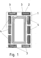
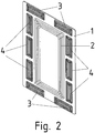
- a secondary winding 2 with first auxiliary windings 3 and auxiliary windings 4 oriented perpendicular thereto is shown on a carrier 1.
- This coil arrangement can be provided on the underbody of a vehicle, to which energy can be supplied from a primary conductor from the secondary winding 2 via an inductive coupling.
- the primary conductor is laid in the ground, and the vehicle can be moved on the ground by means of wheels.
- the primary conductor is laid elongated along the roadway in the ground and the vehicle draws energy while moving along the roadway, the secondary winding and primary conductor being inductively coupled only weakly.
- the primary conductor has a medium-frequency current applied to it, the secondary winding 2 having a capacitance connected in series or in parallel in such a way that the associated resonance frequency corresponds to the medium frequency.
- the center frequency has a value between 10 and 500 kHz, preferably between 15 and 100 kHz.
- the vehicle can be tracked by means of the auxiliary coils (3, 4), since different induction voltages result in the auxiliary coils (3, 4) if the primary conductor deviates from the plane containing the axis of symmetry of the coil arrangement and oriented perpendicular to the plane coil arrangement.
- auxiliary coils are provided in different positions and orientations on the outer circumference of the secondary winding, the incorrect orientation of the vehicle to the primary conductor can be seen.
- a primary winding is laid in the ground instead of the elongated primary conductor.
- an electric charging station can be provided.
- the vehicle can be positioned with its secondary winding over the primary winding and thus the energy storage device, for example a high-voltage accumulator, can be filled with energy.
- the primary winding is also designed as a winding with several turns, although there is an air gap between the primary winding and the secondary winding.
- the ground-laid primary winding is equipped with a coil core that has a center leg around which the primary winding is wound, and if such a coil core, preferably made of ferrite material, is also provided around the secondary winding, an air gap remains that weakens the inductive coupling .
- the mentioned capacity of the secondary winding is connected in the mentioned dimensioning.
- the secondary winding and preferably also the primary winding are designed as flat windings made of stranded wire, the stranded wire being composed of individual individual stranded wires that are electrically insulated from one another. This so-called HF litz wire enables losses to be reduced.
- the secondary winding is preferably designed as a flat winding, in particular as a rectangular flat winding.
- the auxiliary windings (3, 4) are designed by means of conductor tracks of a multi-layer printed circuit board provided as a carrier 1 and can thus be manufactured cost-effectively.
- the secondary winding 2 can also be implemented as a conductor track on such a printed circuit board, but in the case of high powers to be transmitted the above-mentioned design with HF litz wire is preferred.
- the secondary winding and the auxiliary coils (3, 4) are arranged in a corresponding plane.
- auxiliary coils (3, 4) there is also an arrangement of the auxiliary coils (3, 4) in a plane which is aligned parallel to that plane in which the secondary winding is provided.
- the two planar arrangements must then have a non-negligible distance, the plane of the auxiliary coils (3, 4) preferably being further apart from the primary winding than the plane of the secondary winding.
- an arrangement of the auxiliary coils (3, 4) can also be provided, a plane receiving the respective auxiliary coil 3 or 4 being oriented perpendicular to the plane in which the secondary winding is provided.
- the center of gravity of the auxiliary coils is preferably arranged in the plane of the secondary winding.
- the center of gravity of the respective auxiliary coil is also advantageous from the plane of the secondary winding, the center of gravity of the respective auxiliary coil (3, 4) being further away from the plane of the primary winding than the plane of the secondary winding.
- a first part of the auxiliary windings 3 is preferably aligned perpendicular to a second part of the auxiliary windings 4.
- the proportion of the main flux generated by the primary winding, which flows through the auxiliary coils, increases with increasing deviation from the symmetrical, i.e. optimal, position.
- the auxiliary coils are arranged outside the secondary winding and are thus located in the return flow area of the main flux generated by the primary winding when the primary winding is essentially the same or similar in size to the secondary winding.
- auxiliary coils are preferably provided, which are arranged in the corner areas of the secondary winding.
- Primary winding and secondary winding are preferably shaped identically or at least similar. They are preferably of the same size.
- the medium-frequency voltages induced in the auxiliary coils (3, 4) are fed to a respective signal processor 30, which in particular carries out filtering and analog-digital conversion of the signals.
- the thus digital signal streams are fed to a computer 31 which has a microcontroller and processes the signal streams further.
- the computer 31 is connected to a display means 32 for displaying the misorientation and to a parking device 33.
- This parking device enables automatic control of the optimal position, with the control of the vehicle's drives being carried out by a further computer in such a way that the optimal position is attainable.
- the parking device 33 can also only be designed as a parking aid, which supports the driver of the vehicle by means of acoustic and / or optical displays when moving into the optimal position.
- a trough is made in the floor so that the vehicle automatically rolls into the optimal position in a first direction with its front wheels. To achieve the optimal position in the transverse direction, only a slight back and forth movement of the vehicle is then necessary, with the steering wheels being aligned at the appropriate steering angle.
- the auxiliary coils are firmly connected to the primary winding instead of the secondary winding.
- a test signal alternating current or test pulse can be applied to the primary winding, so that a corresponding voltage is induced in the auxiliary winding.
- the voltage induced in response to the test pulse or test alternating current changes.
Landscapes
- Engineering & Computer Science (AREA)
- Power Engineering (AREA)
- Transportation (AREA)
- Mechanical Engineering (AREA)
- Computer Networks & Wireless Communication (AREA)
- Electric Propulsion And Braking For Vehicles (AREA)
- Current-Collector Devices For Electrically Propelled Vehicles (AREA)
Claims (14)
- Système de transmission d'énergie sans contact à un véhicule,
un conducteur primaire, notamment un conducteur primaire posé au sol, pouvant être couplé de manière inductive à un enroulement secondaire (2) du véhicule,
le conducteur primaire étant réalisé sous la forme d'un enroulement primaire,
des enroulements auxiliaires (3, 4), notamment destinés à la détection d'écarts par rapport à une orientation et/ou un positionnement optimal du véhicule par rapport au conducteur primaire, étant présents,
les enroulements auxiliaires (3, 4) étant disposés en-dehors de l'enroulement secondaire (2) ou de l'enroulement primaire,
les enroulements auxiliaires (3, 4) formant notamment un arrangement ayant une symétrie en miroir ou une symétrie de rotation discrète,
le système comportant un moyen qui est configuré pour alimenter le conducteur primaire avec un courant à moyenne fréquence,
caractérisé en ce que
le système comporte un moyen supplémentaire, lequel est configuré pour alimenter au moins l'un des enroulements auxiliaires (3, 4) avec une part de courant dont la plage de fréquences se situe en-dehors de la fréquence du courant à moyenne fréquence, le système comportant un calculateur (31) qui est configuré pour déterminer l'inductance de l'enroulement auxiliaire (3, 4) respectif à partir de la tension et de la part de courant associées respectives appliquées à l'enroulement auxiliaire (3, 4), et pour détecter à partir de cela la pénétration et/ou la présence de corps étrangers métalliques dans la zone entre l'enroulement auxiliaire (3, 4) et le conducteur primaire,
le calculateur (31) étant configuré pour déterminer la nature du métal au moyen de courbes caractéristiques de matériau dépendantes de la fréquence et pour déterminer la température du métal respectif,
et aussi la température du métal utilisé pour la transmission d'énergie, c'est-à-dire la température du matériau du conducteur primaire et/ou du matériau du conducteur secondaire. - Système selon la revendication 1, caractérisé en ce que le conducteur primaire (2) est façonné et/ou posé dans la zone en vis-à-vis du sol de telle sorte qu'une direction préférentielle est marquée, le conducteur primaire étant notamment disposé et configuré dans cette zone de manière symétrique par rapport à un axe de symétrie, l'axe de symétrie étant notamment orienté dans la direction préférentielle.
- Système selon au moins l'une des revendications précédentes, caractérisé en ce que les bobines auxiliaires sont disposées de telle sorte que le champ alternatif magnétique généré par le conducteur primaire alimenté avec un courant alternatif induit une tension dans les enroulements auxiliaires (3, 4), notamment en vue de la détection de l'écart du véhicule par rapport à la position du véhicule à laquelle l'enroulement secondaire (2) et l'enroulement primaire présentent le couplage inductif le plus puissant.
- Système selon au moins l'une des revendications précédentes, caractérisé en ce que le véhicule possède des roues avec lesquelles il peut se déplacer sur le sol dans ou sur lequel est disposé le conducteur primaire.
- Système selon au moins l'une des revendications précédentes, caractérisé en ce que les enroulements auxiliaires (3, 4) et l'enroulement secondaire (2) ou l'enroulement primaire sont disposés parallèlement les uns aux autres, notamment dans le même plan.
- Système selon au moins l'une des revendications précédentes, caractérisé en ce que les enroulements auxiliaires (3, 4) et l'enroulement secondaire (2) ou l'enroulement primaire ne sont pas disposés parallèlement les uns aux autres, les enroulements auxiliaires (3, 4) et l'enroulement secondaire (2) ou l'enroulement primaire étant notamment disposés perpendiculairement les uns aux autres.
- Système selon au moins l'une des revendications précédentes, caractérisé en ce qu'au moins un premier et un deuxième enroulement auxiliaire (3, 4) sont façonnés de la même manière et, lors d'une rotation imaginaire d'une valeur angulaire donnée et d'une translation imaginaire, se mêlent et/ou peuvent être transférés l'un dans l'autre.
- Système selon au moins l'une des revendications précédentes, caractérisé en ce que
au moins un premier enroulement auxiliaire (3) est disposé devant l'enroulement secondaire (2) ou l'enroulement primaire dans le sens du déplacement et au moins un premier enroulement auxiliaire supplémentaire (3) est disposé derrière l'enroulement secondaire (2) ou l'enroulement primaire dans le sens du déplacement et au moins un deuxième enroulement auxiliaire (4) est disposé latéralement à droite à côté de l'enroulement secondaire (2) ou de l'enroulement primaire et
au moins un deuxième enroulement auxiliaire supplémentaire (4) est disposé latéralement à gauche à côté de l'enroulement secondaire (2) ou de l'enroulement primaire. - Système selon au moins l'une des revendications précédentes, caractérisé en ce que l'enroulement secondaire (2) ou l'enroulement primaire est disposé entre deux premiers enroulements auxiliaires (3, 4), l'enroulement secondaire (2) ou l'enroulement primaire étant notamment aussi disposé entre deux enroulements auxiliaires supplémentaires (3, 4) dont la ligne de liaison croise la ligne de liaison des premiers enroulements auxiliaires (3, 4), les lignes de liaison étant notamment perpendiculaires l'une à l'autre, les lignes de liaison croisant notamment les centres de gravité respectifs des enroulements auxiliaires (3, 4).
- Système selon au moins l'une des revendications précédentes, caractérisé en ce qu'en série ou en parallèle de l'enroulement secondaire (2) est branchée une capacité telle que la fréquence de résonance associée est sensiblement égale à la moyenne fréquence.
- Système selon au moins l'une des revendications précédentes, caractérisé en ce que les enroulements auxiliaires (3, 4) sont disposés dans la zone du flux de retour du champ généré par l'enroulement primaire.
- Système selon au moins l'une des revendications précédentes, caractérisé en ce que
l'enroulement secondaire (2) et l'enroulement primaire sont disposés en parallèle l'un de l'autre et/ou en ce que
les enroulements auxiliaires (3, 4) sont disposés au niveau du véhicule ou sont disposés au niveau du sol. - Système selon au moins l'une des revendications précédentes, caractérisé en ce que les signaux, notamment les tensions induites, des enroulements auxiliaires (3, 4) sont acheminés à une unité d'interprétation, laquelle est reliée à un moyen d'affichage d'un positionnement incorrect de l'enroulement secondaire (2) et/ou à un moyen servant d'aide à l'entrée en stationnement ou à une commande d'entrée en stationnement.
- Système selon au moins l'une des revendications précédentes, caractérisé en ce que
au moins l'un des enroulements auxiliaires (3, 4) est alimenté avec une part de courant supplémentaire, notamment avec une part de courant à haute fréquence, notamment une part de courant supérieure dont la fréquence est supérieure à la moyenne fréquence, en vue de la transmission de données,
la deuxième part de courant possédant notamment une fréquence porteuse supérieure à un mégahertz,
et/ou en ce que
un enroulement auxiliaire (3, 4) relié à demeure au conducteur primaire est associé à l'enroulement auxiliaire (3, 4) destiné à la transmission de données, l'écart mutuel entre ces enroulements auxiliaires (3, 4) étant inférieur à l'écart entre l'enroulement auxiliaire (3, 4) destiné à la transmission de données et les autres enroulements, notamment dans la position optimale, c'est-à-dire la position du véhicule à laquelle le couplage inductif du conducteur primaire avec le conducteur secondaire (2) est le plus puissant.
Applications Claiming Priority (2)
| Application Number | Priority Date | Filing Date | Title |
|---|---|---|---|
| DE102010012356.0A DE102010012356B4 (de) | 2010-03-22 | 2010-03-22 | System zur berührungslosen Energieübertragung an ein Fahrzeug |
| PCT/EP2011/001017 WO2011116874A2 (fr) | 2010-03-22 | 2011-03-02 | Système de transfert d'énergie sans contact sur un véhicule |
Publications (2)
| Publication Number | Publication Date |
|---|---|
| EP2550174A2 EP2550174A2 (fr) | 2013-01-30 |
| EP2550174B1 true EP2550174B1 (fr) | 2021-05-12 |
Family
ID=44585421
Family Applications (1)
| Application Number | Title | Priority Date | Filing Date |
|---|---|---|---|
| EP11706758.7A Active EP2550174B1 (fr) | 2010-03-22 | 2011-03-02 | Système de transfert d'énergie sans contact sur un véhicule |
Country Status (3)
| Country | Link |
|---|---|
| EP (1) | EP2550174B1 (fr) |
| DE (1) | DE102010012356B4 (fr) |
| WO (1) | WO2011116874A2 (fr) |
Families Citing this family (28)
| Publication number | Priority date | Publication date | Assignee | Title |
|---|---|---|---|---|
| DE102010050935B4 (de) * | 2010-03-25 | 2013-05-23 | Sew-Eurodrive Gmbh & Co. Kg | Vorrichtung zur berührungslosen Energieübertragung an ein Fahrzeug |
| GB2500691B (en) * | 2012-03-30 | 2016-06-15 | Jaguar Land Rover Ltd | Charging system for a vehicle |
| EP2727759B1 (fr) * | 2012-11-05 | 2015-01-14 | Alcatel Lucent | Procédé et dispositif pour un système d'assistance de véhicule |
| GB2508923A (en) * | 2012-12-17 | 2014-06-18 | Bombardier Transp Gmbh | Inductive power transfer system having inductive sensing array |
| GB2509080A (en) * | 2012-12-19 | 2014-06-25 | Bombardier Transp Gmbh | Inductive power transfer system having an additional receiving device |
| GB2517679A (en) | 2013-06-25 | 2015-03-04 | Bombardier Transp Gmbh | Object detection system and method for operating an object detection system |
| DE102013218471A1 (de) * | 2013-09-16 | 2015-03-19 | Robert Bosch Gmbh | Ladevorrichtung, Empfangsvorrichtung, System und Verfahren zum induktiven Laden eines Akkumulators |
| DE102013110280A1 (de) | 2013-09-18 | 2015-03-19 | Paul Vahle Gmbh & Co. Kg | Positionsbestimmungssystem für Fahrzeuge |
| DE102013227129B4 (de) | 2013-12-23 | 2016-01-14 | Continental Automotive Gmbh | Verfahren zur Erfassung einer Relativposition, Verfahren zum kabellosen Laden eines Fahrzeugs, Orientierungssignalempfänger und induktive Ladevorrichtung |
| DE102014017544A1 (de) * | 2014-11-28 | 2016-06-02 | Sew-Eurodrive Gmbh & Co Kg | Verfahren und System zum induktiven Übertragen von elektrischer Energie an ein Fahrzeug |
| US9912172B2 (en) | 2015-01-14 | 2018-03-06 | Qualcomm Incorporated | Asymmetrically layered stacked coils and/or chamfered ferrite in wireless power transfer applications |
| FR3035831B1 (fr) * | 2015-05-06 | 2018-09-07 | Renault S.A.S | Dispositif de positionnement pour accostage d'un vehicule a une borne de charge sans contact. |
| EP3103674B1 (fr) | 2015-06-12 | 2021-08-18 | Brusa Elektronik AG | Systeme de determination de position, procede de determination de position et systeme inductif de transfert d'energie a l'aide d'un systeme de determination de position |
| US10340752B2 (en) * | 2015-06-23 | 2019-07-02 | Witricity Corporation | Systems, methods and apparatuses for guidance and alignment in electric vehicles wireless inductive charging systems |
| US10411524B2 (en) | 2015-06-23 | 2019-09-10 | Witricity Corporation | Systems, methods and apparatuses for guidance and alignment in electric vehicles wireless inductive charging systems |
| DE102015012368A1 (de) | 2015-09-19 | 2017-03-23 | Audi Ag | Verfahren zur Ermittlung einer eine Relativposition eines Kraftfahrzeugs zu einer stationären, anzufahrenden Ladeeinrichtung beschreibenden Positionsinformation und Anordnung aus einem Kraftfahrzeug und einer stationären, anzufahrenden Ladeeinrichtung |
| DE202016101808U1 (de) * | 2016-04-06 | 2016-04-27 | Fraunhofer-Gesellschaft zur Förderung der angewandten Forschung e.V. | System zur drahtlosen Übertragung von Energie und Daten |
| DE102017002960A1 (de) * | 2016-04-22 | 2017-10-26 | Sew-Eurodrive Gmbh & Co Kg | Verfahren zur Bestimmung eines finanziellen Betrages für eine logistische Leistung in einer Fertigungsanlage und Fertigungsanlage mit einem Fahrzeug zur Durchführung des Verfahrens |
| WO2020002237A1 (fr) * | 2018-06-29 | 2020-01-02 | Brusa Elektronik Ag | Système de charge de véhicule pour charger un accumulateur d'énergie disposé dans un véhicule |
| DE102018213017A1 (de) * | 2018-08-03 | 2020-02-06 | Continental Automotive Gmbh | Verfahren und Vorrichtung zur Ermittlung der relativen Position zweier Spulen zueinander |
| DE102018217008A1 (de) * | 2018-10-04 | 2020-04-09 | Robert Bosch Gmbh | Vorrichtung zur kabellosen Energie- und/oder Datenübertragung |
| DE102018217074A1 (de) * | 2018-10-05 | 2020-04-09 | Continental Automotive Gmbh | Verfahren und Vorrichtung zur Vorbereitung einer Energieübertragung zu einem Fahrzeug mittels eines induktiven Ladesystems |
| DE102018009412A1 (de) | 2018-11-30 | 2019-05-16 | Daimler Ag | Vorrichtung und Verfahren zur Bestimmung einer Position eines Verbindungselments zum Laden eines Verbindungselements zum Laden eines zumindest teilweise elektrisch angetriebenen Fahrzeugs |
| CN110435452B (zh) * | 2019-08-20 | 2023-01-31 | 中兴新能源汽车有限责任公司 | 一种无线充电引导定位系统及方法、地面设备、车载设备 |
| DE102019007172A1 (de) | 2019-10-16 | 2020-07-09 | Daimler Ag | Ladevorrichtung und Verfahren zum induktiven Laden eines elektrischen Energiespeichers eines elektrisch betriebenen Kraftfahrzeugs |
| DE102021205102A1 (de) | 2021-05-19 | 2022-11-24 | Volkswagen Aktiengesellschaft | Verfahren zur induktiven Energieübertragung zwischen einem Fahrzeug und einem Versorgungsnetz, Fahrzeug, Induktionsladevorrichtung und System |
| WO2023194513A1 (fr) * | 2022-04-07 | 2023-10-12 | Mahle International Gmbh | Système de transfert d'énergie par induction |
| DE102022203489A1 (de) * | 2022-04-07 | 2023-10-12 | Mahle International Gmbh | System zur induktiven Energieübertragung |
Citations (18)
| Publication number | Priority date | Publication date | Assignee | Title |
|---|---|---|---|---|
| US4742283A (en) | 1986-11-28 | 1988-05-03 | Inductran Corporation | Guidance system for inductively coupled electric vehicles |
| DE3916610A1 (de) | 1989-05-22 | 1989-12-07 | Goetting Hans Heinrich Jun | Einrichtung zur datenuebertragung und spurfuehrung von fahrzeugen |
| US5548214A (en) | 1991-11-21 | 1996-08-20 | Kaisei Engineer Co., Ltd. | Electromagnetic induction inspection apparatus and method employing frequency sweep of excitation current |
| EP0788212A2 (fr) * | 1996-01-30 | 1997-08-06 | Sumitomo Wiring Systems, Ltd. | Système de connexion et méthode de connexion pour un véhicule automobile électrique |
| US5963035A (en) | 1997-08-21 | 1999-10-05 | Geophex, Ltd. | Electromagnetic induction spectroscopy for identifying hidden objects |
| US20020057075A1 (en) | 2000-09-04 | 2002-05-16 | Satoshi Takashige | Power feeding apparatus, transporter and transport system |
| DE10216422A1 (de) | 2002-04-12 | 2003-10-30 | Wampfler Ag | Vorrichtung zur induktiven Energieversorgung und Führung eines beweglichen Objektes |
| US20050094346A1 (en) | 2001-07-19 | 2005-05-05 | Senstronic | Method for detecting an object of conducting material and corresponding sensor |
| DE102006012562A1 (de) * | 2006-03-16 | 2007-09-27 | Sew-Eurodrive Gmbh & Co. Kg | System und Verfahren |
| US20080164839A1 (en) | 2007-01-09 | 2008-07-10 | Sony Ericsson Mobile Communications Japan, Inc. | Noncontact charging device |
| US20080197957A1 (en) | 2007-02-20 | 2008-08-21 | Seiko Epson Corporation | Coil unit and electronic instrument |
| US20080297107A1 (en) * | 2007-05-28 | 2008-12-04 | Sony Ericsson Mobile Communications Japan, Inc. | Contactless power transferring coil unit, mobile terminal, power transmitting apparatus, and contactless power transferring system |
| US20090015197A1 (en) | 2007-07-13 | 2009-01-15 | Seiko Epson Corporation | Power transmission device and electronic instrument |
| WO2009040998A1 (fr) | 2007-09-27 | 2009-04-02 | Panasonic Corporation | Chargeur sans contact |
| JP2009089463A (ja) | 2007-09-27 | 2009-04-23 | Panasonic Corp | 電子機器および充電システム |
| EP2066001A2 (fr) | 2007-11-30 | 2009-06-03 | Chun-Kil Jung | Système multichargeur sans contact et procédé de contrôle correspondant |
| WO2009081115A1 (fr) | 2007-12-21 | 2009-07-02 | Amway (Europe) Limited | Transfert de puissance inductif |
| JP2010051089A (ja) | 2008-08-21 | 2010-03-04 | Fujitsu Ltd | 非接触送電システム |
Family Cites Families (3)
| Publication number | Priority date | Publication date | Assignee | Title |
|---|---|---|---|---|
| JP3870315B2 (ja) * | 2001-08-08 | 2007-01-17 | 株式会社日立製作所 | 移動体システム |
| DE102007033654B4 (de) * | 2006-09-20 | 2019-08-01 | Sew-Eurodrive Gmbh & Co Kg | System mit Wagen und Basiseinheiten |
| CN101809842A (zh) * | 2007-09-27 | 2010-08-18 | 松下电器产业株式会社 | 电子装置、充电器和充电装置 |
-
2010
- 2010-03-22 DE DE102010012356.0A patent/DE102010012356B4/de active Active
-
2011
- 2011-03-02 EP EP11706758.7A patent/EP2550174B1/fr active Active
- 2011-03-02 WO PCT/EP2011/001017 patent/WO2011116874A2/fr active Application Filing
Patent Citations (18)
| Publication number | Priority date | Publication date | Assignee | Title |
|---|---|---|---|---|
| US4742283A (en) | 1986-11-28 | 1988-05-03 | Inductran Corporation | Guidance system for inductively coupled electric vehicles |
| DE3916610A1 (de) | 1989-05-22 | 1989-12-07 | Goetting Hans Heinrich Jun | Einrichtung zur datenuebertragung und spurfuehrung von fahrzeugen |
| US5548214A (en) | 1991-11-21 | 1996-08-20 | Kaisei Engineer Co., Ltd. | Electromagnetic induction inspection apparatus and method employing frequency sweep of excitation current |
| EP0788212A2 (fr) * | 1996-01-30 | 1997-08-06 | Sumitomo Wiring Systems, Ltd. | Système de connexion et méthode de connexion pour un véhicule automobile électrique |
| US5963035A (en) | 1997-08-21 | 1999-10-05 | Geophex, Ltd. | Electromagnetic induction spectroscopy for identifying hidden objects |
| US20020057075A1 (en) | 2000-09-04 | 2002-05-16 | Satoshi Takashige | Power feeding apparatus, transporter and transport system |
| US20050094346A1 (en) | 2001-07-19 | 2005-05-05 | Senstronic | Method for detecting an object of conducting material and corresponding sensor |
| DE10216422A1 (de) | 2002-04-12 | 2003-10-30 | Wampfler Ag | Vorrichtung zur induktiven Energieversorgung und Führung eines beweglichen Objektes |
| DE102006012562A1 (de) * | 2006-03-16 | 2007-09-27 | Sew-Eurodrive Gmbh & Co. Kg | System und Verfahren |
| US20080164839A1 (en) | 2007-01-09 | 2008-07-10 | Sony Ericsson Mobile Communications Japan, Inc. | Noncontact charging device |
| US20080197957A1 (en) | 2007-02-20 | 2008-08-21 | Seiko Epson Corporation | Coil unit and electronic instrument |
| US20080297107A1 (en) * | 2007-05-28 | 2008-12-04 | Sony Ericsson Mobile Communications Japan, Inc. | Contactless power transferring coil unit, mobile terminal, power transmitting apparatus, and contactless power transferring system |
| US20090015197A1 (en) | 2007-07-13 | 2009-01-15 | Seiko Epson Corporation | Power transmission device and electronic instrument |
| WO2009040998A1 (fr) | 2007-09-27 | 2009-04-02 | Panasonic Corporation | Chargeur sans contact |
| JP2009089463A (ja) | 2007-09-27 | 2009-04-23 | Panasonic Corp | 電子機器および充電システム |
| EP2066001A2 (fr) | 2007-11-30 | 2009-06-03 | Chun-Kil Jung | Système multichargeur sans contact et procédé de contrôle correspondant |
| WO2009081115A1 (fr) | 2007-12-21 | 2009-07-02 | Amway (Europe) Limited | Transfert de puissance inductif |
| JP2010051089A (ja) | 2008-08-21 | 2010-03-04 | Fujitsu Ltd | 非接触送電システム |
Non-Patent Citations (3)
| Title |
|---|
| "Gerthsen Physik", 1 January 2006, SPRINGER, article MESCHEDE DIETER: "7.1.4 WirbelstrSme", pages: 385, XP055895910 |
| SATO, F. ET AL.: "CONTACTLESS ENERGY TRANSMISSION TO MOBILE LOADS BY CLPS - TEST DRIVING OF AN EV WITH STARTER BATTERIES", IEEE TRANSACTIONS ON MAGNETICS, vol. 33, no. 5, September 1997 (1997-09-01), pages 4203 - 4205, XP011086420, DOI: 10.1109/20.619710 |
| SATO, F. ET AL.: "Stable Energy Transmission to Moving Loads utilizing New CLPS", IEEE TRANSACTIONS ON MAGNETICS, vol. 32, no. 5, September 1996 (1996-09-01), pages 5034 - 5036, XP000634212, DOI: 10.1109/20.539367 |
Also Published As
| Publication number | Publication date |
|---|---|
| WO2011116874A2 (fr) | 2011-09-29 |
| DE102010012356B4 (de) | 2021-04-29 |
| EP2550174A2 (fr) | 2013-01-30 |
| WO2011116874A3 (fr) | 2011-12-22 |
| DE102010012356A1 (de) | 2011-09-22 |
Similar Documents
| Publication | Publication Date | Title |
|---|---|---|
| EP2550174B1 (fr) | Système de transfert d'énergie sans contact sur un véhicule | |
| EP2928044B1 (fr) | Système de transmission d'énergie sans contact à partir d'une bobine primaire à un véhicule comprenant une bobine secondaire pouvant être couplée de manière inductive à la bobine primaire, procédé de positionnement d'un véhicule, procédé de détermination d'une direction et procédé de commande de positionnement | |
| EP2782775B1 (fr) | Système de détermination de la position d'objets mobiles les uns par rapport aux autres | |
| DE102012211151B4 (de) | Ladeanordnung und Verfahren zum induktiven Laden eines elektrischen Energiespeichers | |
| US11163313B2 (en) | Methods for positioning vehicles using electric road systems and vehicles operated using these methods | |
| WO2014041176A2 (fr) | Système de détection de corps étrangers en métal pour des systèmes de transmission d'énergie inductive | |
| EP3398804B1 (fr) | Transfert de puissance inductive pour transférer de l'énergie électrique à un véhicule | |
| DE102014207253B4 (de) | Vorrichtung zum Überprüfen eines Vorhandenseins eines elektrisch leitfähigen Körpers und Ladeanordnung zum induktiven Laden eines Elektrofahrzeugs | |
| EP2548088B1 (fr) | Installation et procédé de détermination de la position d'un véhicule à l'intérieur d'une installation, et procédé destiné à établir une trajectoire nominale améliorée pour un véhicule à l'intérieur d'une installation | |
| EP2590836B1 (fr) | Mesure d'une température lors d'une transmission d'énergie sans contact | |
| WO2013143926A1 (fr) | Dispositif pour la transmission de puissance par induction | |
| DE102014202747A1 (de) | Vorrichtung zum Erfassung einer Lageabweichung der passiven Spule gegenüber der Primärspule eines induktiven Ladesystems für ein Fahrzeug sowie zugehöriges Verfahren | |
| WO2013143939A1 (fr) | Dispositif de transmission inductive de puissance | |
| WO2013189530A1 (fr) | Module à bobines de détection, module à bobines de transfert d'énergie et système de détection pour la reconnaissance de corps étrangers électriquement conducteurs | |
| WO2017092950A1 (fr) | Procédé de fonctionnement d'un dispositif de surveillance d'un dispositif de transfert d'énergie par induction | |
| EP3046799B1 (fr) | Procédé et système pour faire fonctionner un véhicule, en particulier un véhicule déplaçable le long d'un sol | |
| EP3028892B1 (fr) | Procede de positionnement d'un vehicule automobile dans une position de chargement et vehicule automobile | |
| DE102017214603B4 (de) | Verfahren und Vorrichtung zur Detektion von elektrisch leitfähigen Fremdkörpern bei der induktiven Energieübertragung | |
| DE102006012562B4 (de) | System und Verfahren | |
| EP3864427B1 (fr) | Dispositif pour déterminer la position d'un objet mobile relativement à un véhicule et véhicule équipé de celui-ci | |
| DE102016212900A1 (de) | Verfahren zum Betrieb einer Ladevorrichtung zur induktiven Energieübertragung | |
| DE102021134196B3 (de) | Verfahren zum Erfassen wenigstens eines Teilbereichs eines Umfelds eines Kraftfahrzeugs mit einer Sensoreinrichtung, Sensoreinrichtung und Kraftfahrzeug | |
| DE102012023708A1 (de) | Verfahren und System zur Bestimmung der relativen Position zwischen einer mobilen Einheit und einem Sender | |
| DE102012015200A1 (de) | Induktiver Näherungsschalter | |
| EP3607408B1 (fr) | Procédé pour déterminer la position d'un mobile guidé sur piste, et système |
Legal Events
| Date | Code | Title | Description |
|---|---|---|---|
| PUAI | Public reference made under article 153(3) epc to a published international application that has entered the european phase |
Free format text: ORIGINAL CODE: 0009012 |
|
| 17P | Request for examination filed |
Effective date: 20121022 |
|
| AK | Designated contracting states |
Kind code of ref document: A2 Designated state(s): AL AT BE BG CH CY CZ DE DK EE ES FI FR GB GR HR HU IE IS IT LI LT LU LV MC MK MT NL NO PL PT RO RS SE SI SK SM TR |
|
| DAX | Request for extension of the european patent (deleted) | ||
| STAA | Information on the status of an ep patent application or granted ep patent |
Free format text: STATUS: EXAMINATION IS IN PROGRESS |
|
| 17Q | First examination report despatched |
Effective date: 20180425 |
|
| REG | Reference to a national code |
Ref country code: DE Ref legal event code: R079 Ref document number: 502011017139 Country of ref document: DE Free format text: PREVIOUS MAIN CLASS: B60L0011180000 Ipc: B60L0053120000 |
|
| RIC1 | Information provided on ipc code assigned before grant |
Ipc: B60L 53/124 20190101ALI20190924BHEP Ipc: B60L 53/12 20190101AFI20190924BHEP Ipc: B60L 53/126 20190101ALI20190924BHEP |
|
| GRAP | Despatch of communication of intention to grant a patent |
Free format text: ORIGINAL CODE: EPIDOSNIGR1 |
|
| STAA | Information on the status of an ep patent application or granted ep patent |
Free format text: STATUS: GRANT OF PATENT IS INTENDED |
|
| INTG | Intention to grant announced |
Effective date: 20201103 |
|
| GRAS | Grant fee paid |
Free format text: ORIGINAL CODE: EPIDOSNIGR3 |
|
| GRAA | (expected) grant |
Free format text: ORIGINAL CODE: 0009210 |
|
| STAA | Information on the status of an ep patent application or granted ep patent |
Free format text: STATUS: THE PATENT HAS BEEN GRANTED |
|
| AK | Designated contracting states |
Kind code of ref document: B1 Designated state(s): AL AT BE BG CH CY CZ DE DK EE ES FI FR GB GR HR HU IE IS IT LI LT LU LV MC MK MT NL NO PL PT RO RS SE SI SK SM TR |
|
| REG | Reference to a national code |
Ref country code: GB Ref legal event code: FG4D Free format text: NOT ENGLISH |
|
| REG | Reference to a national code |
Ref country code: CH Ref legal event code: EP |
|
| REG | Reference to a national code |
Ref country code: DE Ref legal event code: R096 Ref document number: 502011017139 Country of ref document: DE |
|
| REG | Reference to a national code |
Ref country code: IE Ref legal event code: FG4D Free format text: LANGUAGE OF EP DOCUMENT: GERMAN |
|
| REG | Reference to a national code |
Ref country code: AT Ref legal event code: REF Ref document number: 1391975 Country of ref document: AT Kind code of ref document: T Effective date: 20210615 |
|
| REG | Reference to a national code |
Ref country code: LT Ref legal event code: MG9D |
|
| REG | Reference to a national code |
Ref country code: NL Ref legal event code: MP Effective date: 20210512 |
|
| PG25 | Lapsed in a contracting state [announced via postgrant information from national office to epo] |
Ref country code: FI Free format text: LAPSE BECAUSE OF FAILURE TO SUBMIT A TRANSLATION OF THE DESCRIPTION OR TO PAY THE FEE WITHIN THE PRESCRIBED TIME-LIMIT Effective date: 20210512 Ref country code: LT Free format text: LAPSE BECAUSE OF FAILURE TO SUBMIT A TRANSLATION OF THE DESCRIPTION OR TO PAY THE FEE WITHIN THE PRESCRIBED TIME-LIMIT Effective date: 20210512 Ref country code: HR Free format text: LAPSE BECAUSE OF FAILURE TO SUBMIT A TRANSLATION OF THE DESCRIPTION OR TO PAY THE FEE WITHIN THE PRESCRIBED TIME-LIMIT Effective date: 20210512 Ref country code: BG Free format text: LAPSE BECAUSE OF FAILURE TO SUBMIT A TRANSLATION OF THE DESCRIPTION OR TO PAY THE FEE WITHIN THE PRESCRIBED TIME-LIMIT Effective date: 20210812 |
|
| PG25 | Lapsed in a contracting state [announced via postgrant information from national office to epo] |
Ref country code: NO Free format text: LAPSE BECAUSE OF FAILURE TO SUBMIT A TRANSLATION OF THE DESCRIPTION OR TO PAY THE FEE WITHIN THE PRESCRIBED TIME-LIMIT Effective date: 20210812 Ref country code: PT Free format text: LAPSE BECAUSE OF FAILURE TO SUBMIT A TRANSLATION OF THE DESCRIPTION OR TO PAY THE FEE WITHIN THE PRESCRIBED TIME-LIMIT Effective date: 20210913 Ref country code: PL Free format text: LAPSE BECAUSE OF FAILURE TO SUBMIT A TRANSLATION OF THE DESCRIPTION OR TO PAY THE FEE WITHIN THE PRESCRIBED TIME-LIMIT Effective date: 20210512 Ref country code: ES Free format text: LAPSE BECAUSE OF FAILURE TO SUBMIT A TRANSLATION OF THE DESCRIPTION OR TO PAY THE FEE WITHIN THE PRESCRIBED TIME-LIMIT Effective date: 20210512 Ref country code: GR Free format text: LAPSE BECAUSE OF FAILURE TO SUBMIT A TRANSLATION OF THE DESCRIPTION OR TO PAY THE FEE WITHIN THE PRESCRIBED TIME-LIMIT Effective date: 20210813 Ref country code: IS Free format text: LAPSE BECAUSE OF FAILURE TO SUBMIT A TRANSLATION OF THE DESCRIPTION OR TO PAY THE FEE WITHIN THE PRESCRIBED TIME-LIMIT Effective date: 20210912 Ref country code: LV Free format text: LAPSE BECAUSE OF FAILURE TO SUBMIT A TRANSLATION OF THE DESCRIPTION OR TO PAY THE FEE WITHIN THE PRESCRIBED TIME-LIMIT Effective date: 20210512 Ref country code: RS Free format text: LAPSE BECAUSE OF FAILURE TO SUBMIT A TRANSLATION OF THE DESCRIPTION OR TO PAY THE FEE WITHIN THE PRESCRIBED TIME-LIMIT Effective date: 20210512 Ref country code: SE Free format text: LAPSE BECAUSE OF FAILURE TO SUBMIT A TRANSLATION OF THE DESCRIPTION OR TO PAY THE FEE WITHIN THE PRESCRIBED TIME-LIMIT Effective date: 20210512 |
|
| PG25 | Lapsed in a contracting state [announced via postgrant information from national office to epo] |
Ref country code: NL Free format text: LAPSE BECAUSE OF FAILURE TO SUBMIT A TRANSLATION OF THE DESCRIPTION OR TO PAY THE FEE WITHIN THE PRESCRIBED TIME-LIMIT Effective date: 20210512 |
|
| PG25 | Lapsed in a contracting state [announced via postgrant information from national office to epo] |
Ref country code: RO Free format text: LAPSE BECAUSE OF FAILURE TO SUBMIT A TRANSLATION OF THE DESCRIPTION OR TO PAY THE FEE WITHIN THE PRESCRIBED TIME-LIMIT Effective date: 20210512 Ref country code: SK Free format text: LAPSE BECAUSE OF FAILURE TO SUBMIT A TRANSLATION OF THE DESCRIPTION OR TO PAY THE FEE WITHIN THE PRESCRIBED TIME-LIMIT Effective date: 20210512 Ref country code: SM Free format text: LAPSE BECAUSE OF FAILURE TO SUBMIT A TRANSLATION OF THE DESCRIPTION OR TO PAY THE FEE WITHIN THE PRESCRIBED TIME-LIMIT Effective date: 20210512 Ref country code: DK Free format text: LAPSE BECAUSE OF FAILURE TO SUBMIT A TRANSLATION OF THE DESCRIPTION OR TO PAY THE FEE WITHIN THE PRESCRIBED TIME-LIMIT Effective date: 20210512 Ref country code: CZ Free format text: LAPSE BECAUSE OF FAILURE TO SUBMIT A TRANSLATION OF THE DESCRIPTION OR TO PAY THE FEE WITHIN THE PRESCRIBED TIME-LIMIT Effective date: 20210512 Ref country code: EE Free format text: LAPSE BECAUSE OF FAILURE TO SUBMIT A TRANSLATION OF THE DESCRIPTION OR TO PAY THE FEE WITHIN THE PRESCRIBED TIME-LIMIT Effective date: 20210512 |
|
| REG | Reference to a national code |
Ref country code: DE Ref legal event code: R026 Ref document number: 502011017139 Country of ref document: DE |
|
| PLBI | Opposition filed |
Free format text: ORIGINAL CODE: 0009260 |
|
| PLAX | Notice of opposition and request to file observation + time limit sent |
Free format text: ORIGINAL CODE: EPIDOSNOBS2 |
|
| 26 | Opposition filed |
Opponent name: IPT TECHNOLOGY GMBH Effective date: 20220214 |
|
| PG25 | Lapsed in a contracting state [announced via postgrant information from national office to epo] |
Ref country code: IS Free format text: LAPSE BECAUSE OF FAILURE TO SUBMIT A TRANSLATION OF THE DESCRIPTION OR TO PAY THE FEE WITHIN THE PRESCRIBED TIME-LIMIT Effective date: 20210912 Ref country code: AL Free format text: LAPSE BECAUSE OF FAILURE TO SUBMIT A TRANSLATION OF THE DESCRIPTION OR TO PAY THE FEE WITHIN THE PRESCRIBED TIME-LIMIT Effective date: 20210512 |
|
| PLBB | Reply of patent proprietor to notice(s) of opposition received |
Free format text: ORIGINAL CODE: EPIDOSNOBS3 |
|
| PG25 | Lapsed in a contracting state [announced via postgrant information from national office to epo] |
Ref country code: IT Free format text: LAPSE BECAUSE OF FAILURE TO SUBMIT A TRANSLATION OF THE DESCRIPTION OR TO PAY THE FEE WITHIN THE PRESCRIBED TIME-LIMIT Effective date: 20210512 |
|
| PG25 | Lapsed in a contracting state [announced via postgrant information from national office to epo] |
Ref country code: MC Free format text: LAPSE BECAUSE OF FAILURE TO SUBMIT A TRANSLATION OF THE DESCRIPTION OR TO PAY THE FEE WITHIN THE PRESCRIBED TIME-LIMIT Effective date: 20210512 |
|
| REG | Reference to a national code |
Ref country code: CH Ref legal event code: PL |
|
| GBPC | Gb: european patent ceased through non-payment of renewal fee |
Effective date: 20220302 |
|
| REG | Reference to a national code |
Ref country code: BE Ref legal event code: MM Effective date: 20220331 |
|
| PG25 | Lapsed in a contracting state [announced via postgrant information from national office to epo] |
Ref country code: LU Free format text: LAPSE BECAUSE OF NON-PAYMENT OF DUE FEES Effective date: 20220302 Ref country code: LI Free format text: LAPSE BECAUSE OF NON-PAYMENT OF DUE FEES Effective date: 20220331 Ref country code: IE Free format text: LAPSE BECAUSE OF NON-PAYMENT OF DUE FEES Effective date: 20220302 Ref country code: GB Free format text: LAPSE BECAUSE OF NON-PAYMENT OF DUE FEES Effective date: 20220302 Ref country code: FR Free format text: LAPSE BECAUSE OF NON-PAYMENT OF DUE FEES Effective date: 20220331 Ref country code: CH Free format text: LAPSE BECAUSE OF NON-PAYMENT OF DUE FEES Effective date: 20220331 |
|
| PG25 | Lapsed in a contracting state [announced via postgrant information from national office to epo] |
Ref country code: BE Free format text: LAPSE BECAUSE OF NON-PAYMENT OF DUE FEES Effective date: 20220331 |
|
| PLAB | Opposition data, opponent's data or that of the opponent's representative modified |
Free format text: ORIGINAL CODE: 0009299OPPO |
|
| R26 | Opposition filed (corrected) |
Opponent name: IPT TECHNOLOGY GMBH Effective date: 20220214 |
|
| REG | Reference to a national code |
Ref country code: AT Ref legal event code: MM01 Ref document number: 1391975 Country of ref document: AT Kind code of ref document: T Effective date: 20220302 |
|
| PG25 | Lapsed in a contracting state [announced via postgrant information from national office to epo] |
Ref country code: AT Free format text: LAPSE BECAUSE OF NON-PAYMENT OF DUE FEES Effective date: 20220302 |
|
| PG25 | Lapsed in a contracting state [announced via postgrant information from national office to epo] |
Ref country code: HU Free format text: LAPSE BECAUSE OF FAILURE TO SUBMIT A TRANSLATION OF THE DESCRIPTION OR TO PAY THE FEE WITHIN THE PRESCRIBED TIME-LIMIT; INVALID AB INITIO Effective date: 20110302 |
|
| PG25 | Lapsed in a contracting state [announced via postgrant information from national office to epo] |
Ref country code: MK Free format text: LAPSE BECAUSE OF FAILURE TO SUBMIT A TRANSLATION OF THE DESCRIPTION OR TO PAY THE FEE WITHIN THE PRESCRIBED TIME-LIMIT Effective date: 20210512 Ref country code: CY Free format text: LAPSE BECAUSE OF FAILURE TO SUBMIT A TRANSLATION OF THE DESCRIPTION OR TO PAY THE FEE WITHIN THE PRESCRIBED TIME-LIMIT Effective date: 20210512 |
|
| PGFP | Annual fee paid to national office [announced via postgrant information from national office to epo] |
Ref country code: DE Payment date: 20240331 Year of fee payment: 14 |