EP2550144B1 - Aktuatorhaltesystem - Google Patents
Aktuatorhaltesystem Download PDFInfo
- Publication number
- EP2550144B1 EP2550144B1 EP11712420.6A EP11712420A EP2550144B1 EP 2550144 B1 EP2550144 B1 EP 2550144B1 EP 11712420 A EP11712420 A EP 11712420A EP 2550144 B1 EP2550144 B1 EP 2550144B1
- Authority
- EP
- European Patent Office
- Prior art keywords
- actuator
- manifold
- clamp plate
- mount
- conductive
- Prior art date
- Legal status (The legal status is an assumption and is not a legal conclusion. Google has not performed a legal analysis and makes no representation as to the accuracy of the status listed.)
- Active
Links
Images






Classifications
-
- B—PERFORMING OPERATIONS; TRANSPORTING
- B29—WORKING OF PLASTICS; WORKING OF SUBSTANCES IN A PLASTIC STATE IN GENERAL
- B29C—SHAPING OR JOINING OF PLASTICS; SHAPING OF MATERIAL IN A PLASTIC STATE, NOT OTHERWISE PROVIDED FOR; AFTER-TREATMENT OF THE SHAPED PRODUCTS, e.g. REPAIRING
- B29C45/00—Injection moulding, i.e. forcing the required volume of moulding material through a nozzle into a closed mould; Apparatus therefor
- B29C45/17—Component parts, details or accessories; Auxiliary operations
- B29C45/26—Moulds
- B29C45/27—Sprue channels ; Runner channels or runner nozzles
- B29C45/28—Closure devices therefor
- B29C45/2806—Closure devices therefor consisting of needle valve systems
- B29C45/281—Drive means therefor
-
- B—PERFORMING OPERATIONS; TRANSPORTING
- B23—MACHINE TOOLS; METAL-WORKING NOT OTHERWISE PROVIDED FOR
- B23P—METAL-WORKING NOT OTHERWISE PROVIDED FOR; COMBINED OPERATIONS; UNIVERSAL MACHINE TOOLS
- B23P17/00—Metal-working operations, not covered by a single other subclass or another group in this subclass
- B23P17/04—Metal-working operations, not covered by a single other subclass or another group in this subclass characterised by the nature of the material involved or the kind of product independently of its shape
-
- B—PERFORMING OPERATIONS; TRANSPORTING
- B29—WORKING OF PLASTICS; WORKING OF SUBSTANCES IN A PLASTIC STATE IN GENERAL
- B29C—SHAPING OR JOINING OF PLASTICS; SHAPING OF MATERIAL IN A PLASTIC STATE, NOT OTHERWISE PROVIDED FOR; AFTER-TREATMENT OF THE SHAPED PRODUCTS, e.g. REPAIRING
- B29C45/00—Injection moulding, i.e. forcing the required volume of moulding material through a nozzle into a closed mould; Apparatus therefor
- B29C45/17—Component parts, details or accessories; Auxiliary operations
- B29C45/26—Moulds
- B29C45/27—Sprue channels ; Runner channels or runner nozzles
- B29C45/2725—Manifolds
-
- B—PERFORMING OPERATIONS; TRANSPORTING
- B29—WORKING OF PLASTICS; WORKING OF SUBSTANCES IN A PLASTIC STATE IN GENERAL
- B29C—SHAPING OR JOINING OF PLASTICS; SHAPING OF MATERIAL IN A PLASTIC STATE, NOT OTHERWISE PROVIDED FOR; AFTER-TREATMENT OF THE SHAPED PRODUCTS, e.g. REPAIRING
- B29C45/00—Injection moulding, i.e. forcing the required volume of moulding material through a nozzle into a closed mould; Apparatus therefor
- B29C45/17—Component parts, details or accessories; Auxiliary operations
- B29C45/26—Moulds
- B29C45/27—Sprue channels ; Runner channels or runner nozzles
- B29C45/2737—Heating or cooling means therefor
-
- B—PERFORMING OPERATIONS; TRANSPORTING
- B29—WORKING OF PLASTICS; WORKING OF SUBSTANCES IN A PLASTIC STATE IN GENERAL
- B29C—SHAPING OR JOINING OF PLASTICS; SHAPING OF MATERIAL IN A PLASTIC STATE, NOT OTHERWISE PROVIDED FOR; AFTER-TREATMENT OF THE SHAPED PRODUCTS, e.g. REPAIRING
- B29C45/00—Injection moulding, i.e. forcing the required volume of moulding material through a nozzle into a closed mould; Apparatus therefor
- B29C45/17—Component parts, details or accessories; Auxiliary operations
- B29C45/26—Moulds
- B29C45/27—Sprue channels ; Runner channels or runner nozzles
- B29C2045/277—Spacer means or pressure pads between manifold and mould plates
-
- B—PERFORMING OPERATIONS; TRANSPORTING
- B29—WORKING OF PLASTICS; WORKING OF SUBSTANCES IN A PLASTIC STATE IN GENERAL
- B29C—SHAPING OR JOINING OF PLASTICS; SHAPING OF MATERIAL IN A PLASTIC STATE, NOT OTHERWISE PROVIDED FOR; AFTER-TREATMENT OF THE SHAPED PRODUCTS, e.g. REPAIRING
- B29C45/00—Injection moulding, i.e. forcing the required volume of moulding material through a nozzle into a closed mould; Apparatus therefor
- B29C45/17—Component parts, details or accessories; Auxiliary operations
- B29C45/72—Heating or cooling
- B29C45/73—Heating or cooling of the mould
- B29C45/7331—Heat transfer elements, e.g. heat pipes
-
- Y—GENERAL TAGGING OF NEW TECHNOLOGICAL DEVELOPMENTS; GENERAL TAGGING OF CROSS-SECTIONAL TECHNOLOGIES SPANNING OVER SEVERAL SECTIONS OF THE IPC; TECHNICAL SUBJECTS COVERED BY FORMER USPC CROSS-REFERENCE ART COLLECTIONS [XRACs] AND DIGESTS
- Y10—TECHNICAL SUBJECTS COVERED BY FORMER USPC
- Y10T—TECHNICAL SUBJECTS COVERED BY FORMER US CLASSIFICATION
- Y10T29/00—Metal working
- Y10T29/49—Method of mechanical manufacture
- Y10T29/49826—Assembling or joining
Definitions
- the present invention relates to injection molding equipment generally and more particularly to assemblies for mounting an actuator to a manifold.
- Heated hotrunners, manifolds, nozzles, nozzle tips and gate areas that are used in injection molding systems serve to receive and route molten material, typically polymer or plastic, under condtions of high pressure and high temperature.
- molten material typically polymer or plastic
- a natural consequence of the use of such high temperatures under which the molten material is injected into the manifold or distribution system is that operating components of the system such as an actuator that are incidentally in thermal communication with or disposed in close proximity to such heated components are themselves subjected to such high temperatures.
- an injection molding apparatus comprising a clamp plate, a heated manifold and a mold, a system for mounting an actuator to the manifold and the clamp plate, the system comprising:
- the clamp plate, manifold and mold are typically assembled together with the actuator and the mount in an assembled operating arrangement such that the third thermally conductive surfaces of the mount are in compressed contact with the clamp plate under a spring force.
- the spring force in such an embodiment is created by a deformation of a portion of the mount.
- the manifold is typically heated to an elevated temperature from between about 300 degrees and about 800 degrees F, typically to between about 400 and about 600 degrees F.
- the clamping plate is typically cooled to a temperature significantly less than about 300 degrees F and typically to less than about 150 degrees F.
- the system preferably includes a thermally conductive cooling device having first and second mounting surfaces disposed between the second mounting surface of the mount and the heated manifold, the mount being mounted in thermally conductive communication with the first mounting surface of the cooling device and the manifold being mounted in thermally conductive communication with the second mounting surface of the cooling device.
- the cooling device typically comprises a thermally conductive metal device that is cooled to a temperature significantly less than about 300 degrees, typically to less than about 150 degrees F, preferably to less than about 100 degrees F.
- the actuator or a body surface thereof is typically mounted in thermally conductive contact engagement with the first opposing surface of the mount.
- the clamp plate or a body surface thereof is typically mounted in thermally conductive contact or engagement with the one or more third thermally conductive surfaces of the mount.
- the cooling device or a body surface thereof is typically mounted in thermally conductive contact or engagement with the second opposing surface of the mount.
- the mount typically comprises a plate having a primary mounting surface that receives and engages a body surface of the actuator.
- the plate typically has projections that are arranged and configured to extend beyond the engaged body surface of the actuator such that the projections of the plate are formed into the third surfaces of the plate that laterally extend into thermally conductive contact engagement with one or more body surfaces of the clamp plate.
- the engaged surfaces of the clamp plate and the mount cause the actuator to be cooled by conduction of heat from the actuator to the clamp plate through the thermally conductive mount.
- the engaged surfaces of the cooling device and the mount further enable the mount to be cooled thus also serving to cool the actuator via conduction of heat from the actuator to the cooling device through the mount.
- the projections of the mount include a spring, the clamp plate, the mold, the manifold, the actuator and the mount being assembled together in an arrangement wherein the spring is loaded urging the third surfaces into compressed engagement with the clamp plate.
- the clamp plate is preferably mounted in a position upstream from and in spaced thermal isolation from the manifold.
- the clamp plate is most preferably cooled.
- the actuator is connected to a valve pin that extends through a fluid material feed bore in the manifold.
- the valve pin preferably extends from the actuator and is mounted to the manifold.
- an injection molding apparatus having a clamp plate and a heated manifold , a system for mounting an actuator to the manifold and the clamp plate, the system comprising:
- the mount includes a spring, the clamp plate, the mold, the manifold, the actuator and the mount being assembled together in an arrangement wherein the spring is loaded urging the extensions into compressed engagement with the clamp plate.
- an injection molding apparatus having a clamp plate and a heated manifold , a system for mounting an actuator to the manifold and the clamp plate, the system comprising:
- the apparatus preferably comprises a cooling device disposed between the actuator and the manifold and separating the actuator from direct contact with the manifold, the cooling device having a first mounting surface in thermally conductive communication with a mounting surface of the actuator and a second mounting surface in thermally conductive communication with a mounting surface of the manifold.
- the cooling device typically comprises a thermally conductive metal device that is cooled to a temperature significantly less than about 300 degrees, typically to less than about 150 degrees F, preferably to less than about 100 degrees F.
- the first conductive surface of the mount is adapted to be slidably engaged with an outside surface of the actuator, the second conductive surface of the mount being adjustable in distance toward and away from the actuator by sliding movement of the first conductive surface on the outside surface of the actuator.
- the first conductive surface of the mount is preferably maintained or secured in compressed contact with the outside surface of the actuator.
- the clamp plate is preferably mounted in a position upstream from and in spaced thermal isolation from the manifold.
- the clamp plate is most preferably cooled.
- the mount can include a spring disposed between a body surface of the actuator and the mount, the clamp plate, the mold, the manifold, the actuator and the mount being assembled together in an arrangement wherein the spring is compressed urging the second conductive surface of the mount into compressed engagement with the clamp plate.
- the actuator is connected to a valve pin that extends through a fluid material feed bore in the manifold.
- the valve pin preferably extends from the actuator and is mounted to the manifold.
- an injection molding apparatus having a clamp plate and a heated manifold , a system for mounting an actuator to the manifold and the clamp plate, the system comprising:
- the mount can include a spring disposed between a body surface of the actuator and the mount, the clamp plate, the mold, the manifold, the actuator and the mount being assembled together in an arrangement wherein the spring is compressed urging the second conductive surface of the mount into compressed engagement with the clamp plate.
- the clamp plate is adapted to be mounted to the mold and the actuator is adapted to be mounted to the manifold in an arrangement such that a spring is compressed to exert the spring force on assembly and mounting of the clamp plate to the mold.
- an injection molding apparatus comprising a clamp plate, a heated manifold and a mold, a system for mounting an actuator to the manifold and the clamp plate, the system comprising:
- the actuator is mounted in thermally conductive communication with the heated manifold.
- the clamp plate is adapted to be mounted to the mold and the actuator is adapted to be mounted to the manifold in an arrangement such that a spring is compressed to exert the spring force on assembly and mounting of the the clamp plate to the mold.
- a method of mounting an actuator that drives a valve pin in an injection molding system comprising a manifold, a mold and a clamp plate, the method comprising:
- the method further comprises mounting the heat transfer mount to the heat conductive surface of the actuator such that the first conductive surface of the heat transfer mount is maintained in sliding heat conductive contact with the heat conductive surface of the actuator.
- the method preferably further comprises disposing a cooled plate between the actuator and the manifold in thermally conductive communication therewith.
- the method can further comprise driving the valve pin through a fluid feed bore within the manifold.
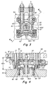
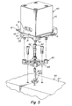
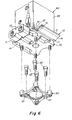
- Figs. 1-9 show an actuator 40 comprised of a thermally conductive metal housing 45 having a bottom surface 41 mounted in compressed engagement/contact with a top surface 12 of a highly thermally conductive plate 10.
- the actuator 40 is surrounded by and/or mounted within a complementary receiving recess CA of large thermally conductive metal clamp plate 20 which is proactively cooled with water pumped through cooling channels 25 during operation of the injection molding apparatus.
- the apparatus generally is comprised of an injection molding machine 70, Fig. 1 , which injects fluid material into the flow channels 53 of a hotrunner or manifold 50 which is heated to an elevated temperature by heaters 55.
- the hotrunner 50 is mounted between a cooled upstream clamping plate or clamp plate 20 and a downstream mold 500.
- the fluid material is routed from the runners 53 of the hotrunner 50 into the cavity of a mold 500, the mold typically being cooled in the same manner as the clamp plate 20 is cooled.
- the actuator 40 is mounted to the manifold 50, separated from direct contact with the manifold 50 in the Figs. 1-9 embodiments by both the mounting plate 10, a cooling device 30 and mount 60 for the cooling device.
- the actuator is separated from direct contact with the manifold by the cooling device 30 and the mount 60 for the cooling device.
- a bottom surface 41 of the body 45 of the actuator 40 is mounted in thermally conductive contact with a top surface 12 of the highly thermally conductive cooling or mounting plate 10.
- the bottom or downstream surface 13 of the cooling or mount plate 10 is in turn mounted in compressed contact with the top or upstream facing surface 31 of highly thermally conductive metal cooling block 30.
- the cooling block 30 is proactively cooled with water pumped through cooling channels 33 during active operation of the entire apparatus. As shown the cooling block is mounted on a mount 60 the bottom surfaces 63 of which are mounted in direct contact with the top surface 57 of the heated hotrunner 50. During operation of the apparatus, the cooled cooling block 30 serves to maintain the actuator 40 cool and/or relatively insulated from the heated manifold 50.
- the cooling block 30 is mounted on the intermediate mount 60 which itself is mounted in engagement contact with the body or top surface 57 of the heated manifold 50 via bolts 62. Heat from the heated manifold 50 is thus thermally conducted or transferred through the bolts 62 and through the mount 60, block 30 and mount 10 to the actuator 40.
- the highly thermally conductive cooling mount 10 has lateral extensions or wings 14 that are configured and arranged to have an upper or upstream facing surface(s) 11 that make compressed contact with a lower surface 21 of the cooled clamp plate 20 thus enabling heat that may otherwise flow from the manifold 50 to/through the cooling block 30 and the plate 10 and the actuator 40 to be conductively transferred to the cooled clamp plate 20.
- the actuator 40 and its associated components plate 30 and mount 60 collectively have a mounting height AH extending upstream from the surface 57 of the heated manifold 50.
- the receiving cavity 20 of the clamp plate 20 has a receiving depth CH of sufficient size together with space S to accommodate receipt of the mounting height AH of the assembly of the actuator 40, plates 100, and cooling device 30.
- some portion of the heat that is conducted to the body of the actuator 40 from the heated manifold 50 is re-routed or conducted to the wings 14 via heat conductive engagement of the surfaces 13 and 31.
- Such heat that is conducted to the wings 14 is in turn conducted to the clamp plate surface 21 via engagement with the spring-loaded heat conductive surface 11, the clamp plate 20 acting as a heat sink to help lower the temperature of the body 45 of the actuator 40.
- the system is adapted and arranged so that when assembled, the clamp plate 20 is thermally isolated from the heated manifold by an insulating air space S by which the clamp plate 20 is spaced apart from the upstream surface 57 of the manifold 50.
- the clamp plate 20 is maintained in such a thermally isolated position relative to the manifold 50, the clamp plate having little to no direct thermally conductive contact with the manifold 50 other than incidentally through a less than about 2 inch square area of contact that may exist between a spacer 48 and the clamp plate 20 and between the spacer 48 and the manifold 50, the spacer 48 being disposed between the clamp plate 20 and the manifold for purposes of ensuring proper positioning of the manifold 50 relative to the clamp plate 20.
- the clamp plate 20 is typically cooled with a cooling fluid pumped and flowing through cooling channels 25 in the body of the clamp plate 20.
- thermally conductive direct contact between the surfaces 11 and the clamp plate surface 21 enable heat to transfer from the body 45 of the actuator 40 to the clamp plate 20, the heat being readily dissipated by the cooled clamp plate 20.
- the winged cooling plate 10 is comprised of a highly thermally conductive material.
- the cooling plate assembly 10, 30, 60 has an assembled height ASH when mounted to the manifold surface 57 that extends from the downstream-most mounting surface 63 of the mount 60 to the upstream facing engagement surface 11 of the wings 14 of the cooling plate 10, Figs. 4-6 .
- the length of the spacing distance S is predetermined relative to the assembled height ASH such that when the components of the system including the clamp plate 20 and manifold 50 are assembled and connected together with the mold 500, the upstream facing surfaces 11 of the wings 14 engage the downstream facing surface 21 of the clamp plate 20 under a selected amount of compression created by the downstream bending of wings 14 resulting in upward spring force SF being exerted by wings 14 urging surfaces 11 in an upstream direction into compressed engagement with surface 21 of cooled clamp plate 20.
- the system is adapted to have an assembled configuration where on assembly together of the clamp plate 20, mold 500, manifold 50, actuator 40 and mount 10, the spring force in the wings 14 is loaded thus urging the surfaces 11 into thermally conductive compressed engagement with the surface 21.
- the compressed contact between thermally conductive metal surfaces 11 and 21 enables heat flow between the bodies 10, 20 having the metal surfaces.
- the cooling device 30 is typically cooled to less than about 100 degrees Fahrenheit and is actively cooled by water injection flow during an injection cycle. When the injection molding machine 70 is shut down, all of the other components of the apparatus including the cooling device are also typically shut down causing the actuator 40 to be more prone and subject to being heated up by the manifold 50.
- the manifold 50 is very large in size and mass and thus takes a longer time to cool down on shutting the apparatus down.
- the cooling block 30 is not proactively working to maintain the actuator 40 cool while the manifold 50 simultaneously remains at a very high temperature thus causing elevated heat transfer from the manifold 50 through the mount 60 and the block 30 to the actuator 40.
- the thermally conductive plate-mount 10 serves to divert the manifold heat via the wings 14 to the relatively cool clamp plate 20 which is itself a very large mass of material which is not easily heated up by the hot manifold on shut down.
- the thermally conductive mount 10 thus essentially cools the actuator 40 or at least works to minimize or lessen the amount of heat transfer from the manifold 50 to the actuator 40 without active cooling by the cooling device 30.
- a spacer 80 is compressibly connected to selected position on the downstream facing surface 21 of the clamp plate 20 such that the upstream facing surface 11 of the wings 14 engage a downstream facing surface 83 of the spacers 80 rather than directly to the clamp plate surface 21.
- the spacers 80 are comprised of a highly thermally conductive material so that heat conducts readily from the wings 14 to the spacers 80 and in turn from the spacers to the clamp plate body 20.
- the spacers 80 can be employed to increase the size of the insulating air space S1 or for otherwise accommodating thickness, height or other size variations in the components 10, 30, 60 or other components that may be employed to assemble and mount the cooling plate 10. As in the Figs.
- the size, depth and height of the various components of the system shown in Figs. 8 , 9 are preselected such that when the components of the system are all assembled, in particular when the clamp plate 20 and manifold are mounted to the mold 500 and the spacers 48 and 80 are assembled and connected to the clamp plate 20, the upstream facing surfaces 11 of the wings 14 engage the downstream facing surface 83 of the spacers 80 under a selected amount of compression created by the downstream bending of wings 14 resulting in upward spring force SF being exerted by wings 14 urging surfaces 11 in an upstream direction into compressed engagement with surfaces 83 of spacers 80.
- the clamp plate 20 is preferably thermally isolated from the heated manifold 50.
- the actuator 40 is mounted to the manifold 50, separated from direct contact with the manifold 50 by the cooling device 30 and the mount 60 for the cooling device.
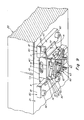
- the Figs. 10 , 11 apparatus has cooling or heat deflector plates 100 which are flanged as shown.
- the plates 100 have one or more slots 150 that slidably receive projections 160 from a sidewall 43 of the actuator 40 such that the plates 150 can be slid or moved in an upstream or downstream direction 180 relative to the actuator 40.
- the projections 160 comprise a bolt 160b that extends laterally through the slots 150, the bolts having a diameter that is complementary to the width W of the slots 150 so that the plate 100 is prevented from travelling in front to back direction T and is slidable in an up and down direction UD.
- the projections 160 preferably have a head portion 160h having a diameter that is wider than the width W of the slot 150, the head portion 160h having an inwardly facing surface 160a that engages the outwardly facing edge surfaces 150a of the slots 150 thus preventing the plates 100 from moving in a lateral direction L away from the outside lateral surface 43 of the body of the actuator 40.
- the bolts 160b are screwed and secured a selected distance into the depth of the body of the actuator 40 as shown in Fig.
- the inside surfaces 104i that are engaged with the outside surface 43 of the actuator are thus in heat conductive contact with the sidewall 43 or other outside surface of the actuator 40 as may alternatively be selected for engagement of the plates 100 therewith.
- the plates 100 have a top flanged portion 106 that extends and is disposed between a top end surface 47 of the actuator 40 and a downstream facing surface 140 of the top clamp plate 20.
- the top flanged portion 106 of the cooling or deflector plates 100 have a top or upstream facing surface 130 that is urged by spring force 128 of spring 120 into engagement and heat conductive contact with the downstream facing surface 140 of the top clamp plate.
- a plate or leaf spring 120 is disposed in engagement with the top surface 47 of the actuator 40.
- the leaf spring 120 is configured and arranged having a pair of laterally extending arms 120 having terminal ends 122 that engage with a pair of receiving or bearing surfaces 102 of the plate(s) 100.
- the ends 122 of the spring 120 engage with the plates at about the area of the bend in the plates 100 that forms the flange.
- the ends 122 of the arms exert an upstream directed spring force 128 against the plates 100 that urges the upstream facing surfaces 130 of the plates 100 into heat conductive engagement with the downstream facing surface 140 of the top clamp plate.
- heat that is conducted to the body of the actuator 40 from the heated manifold 50 is re-routed or conducted to the side portions 104 of the plates 100 via heat conductive engagement of the inside surfaces 104i of the sides 104 with the outside surfaces 43 of the actuator 40.
- Such heat that is conducted to the side portions 104 is in turn conducted to the top portions 106 which is in turn conducted to the body of the clamp plate 20 via the spring-loaded 128 heat conductive contact between the top surface 130 of the top portions 106 with the surface 140 of the top clamp plate 20.
- the body of the actuator 40 is mounted directly on and in heat conductive engagement with the cooling block 30.
- the actuator 40 in combination with the cooling plates 100 and cooling device is mounted and secured via bolts 62 onto the upstream facing surface 57 of the heated manifold 50.
- the actuator 40 and associated components have a certain height AH that they extend upstream from the surface 57.
- the mounting height AH of the assembly of the actuator 40, plates 100, and cooling device 30 and the depth CH of the receiving aperture CA in the clamp plate 20 are preselected so that when the components of the system including the clamp plate 20 and manifold 50 are assembled and connected together with the mold 500, the upstream facing surface 130 of the plates 100 engage the downstream facing surface 140 of the clamp plate 20 under compression created by compression of springs 120 resulting in the spring force 128 urging surface 130 in an upstream direction into compressed engagement with surface 140.
- the inside surfaces 104i of the plates 100 are free to slide upstream and downstream UD against the outside surface 43 of the actuator 40, the plates themselves being free to slide upstream and downstream UD to accommodate any changes in the distance AH that can or may occur as a result of expansion or contraction of the length, width or depth of the manifold 50, plates 30, 60 or 20 or the actuator body 40 or other components of the system when the assembled system is raised to elevated operating temperature or lowered from operating temperature to room temperature.
- the system is adapted and arranged so that when assembled, the clamp plate 20 is thermally isolated from the heated manifold by an insulating space S by which the clamp plate is spaced apart from the manifold.
- the insulating space S results from the pre-selection of the actuator height AH relative to the cavity height CH where the spring force 128 occurs on assembly of the clamp plate 20 together with the mold 500 and manifold 50.
- the clamp plate 20 is isolated from and mounted to either or both the mold 500 and manifold 50 such that the clamp plate 20 is maintained in a thermally isolated position relative to the manifold 50 spaced by S, the clamp plate having little to no direct thermally conductive contact with the manifold 50 other than incidentally through a less than about 2 inch square area of contact that may exist between a spacer 48 or other component and the clamp plate 20, the spacer 48 being in similar conductive contact with the manifold 50.
- the spacer 48 is disposed between the clamp plate 20 and the manifold 50 for purposes of ensuring the proper positioning of the manifold 50 relative to the clamp plate 20.
- the clamp plate 20 may alternatively be mounted to the mold 500 without conductive contact with the manifold 50 such that insulating space S is maintained.
- the clamp plate 20 is typically cooled with a cooling fluid disposed and flowing through cooling channels 25 in the body of the clamp plate 20.
- thermally conductive direct contact between the slidable plates 100 and the clamp plate 20 enable heat to transfer from the body of the actuator 40 to the clamp plate, the heat being readily dissipated by the cooled clamp plate 20.
- the downstream facing surfaces 60a of a downstream mount 60 for the cooling device 30 are mounted in compressed contact with the top surface 57 of the manifold 50 when the system is fully assembled.
- the cooling block 30 is proactively cooled with water pumped through cooling channels 33 during active operation of the entire apparatus.
- the cooled cooling block 30 serves to maintain the actuator 40 cool and/or relatively insulated from the heated manifold 50.
- the cooling block 30 is mounted on an intermediate mount 60 which itself is mounted in engagement contact with the body or upstream facing surface 57 of the heated manifold 50 via bolts 62. Heat from the heated manifold 50 is thus thermally conducted or transferred to the actuator 40 through the bolts 62, mount 60 and block 30.
- the mold 500 is preferably also thermally isolated from the manifold, there being on incidental contact between certain components such as an injection nozzle with both the manifold and the mold.
- a valve pin 400 is interconnected at an upstream end to a piston of the actuator 40.
- the valve pin 400 extends from the actuator 40 first into and through a fluid material feed bore 53 in the manifold 50 itself (as opposed to directly into the bore of the nozzle 58), the manifold bore 53 communicating with and feeding molten fluid material into the bore of the nozzle 58 that leads to and feeds into the cavity of the mold 500.
- the valve pin 400 is typically mounted to the manifold 50 such that the valve pin 400 moves laterally with the manifold 50 as the manifold expands on heating to operating temperature.
- the valve pin 400 is mounted to the manifold 50 via a bushing 420 or alternatively by extending through a complementary aperture (embodiment not shown) provided in the body of the manifold 50 itself that receives the valve pin 400.
Landscapes
- Engineering & Computer Science (AREA)
- Mechanical Engineering (AREA)
- Manufacturing & Machinery (AREA)
- Moulds For Moulding Plastics Or The Like (AREA)
- Injection Moulding Of Plastics Or The Like (AREA)
Claims (13)
- Vorrichtung zum Spritzgießen, umfassend eine Klemmplatte (20), einen beheizten Verteilerkanal (50), und ein Formwerkzeug (500), ein System zum Halten eines Aktuators (40) am Verteilerkanal (50) und an der Klemmplatte (20), dadurch gekennzeichnet, dass das System umfasst:eine Halterung (10) aus einem thermisch leitenden Material mit ersten (104i) und zweiten (130) wärmeleitenden Oberflächen, welche zwischen der Klemmplatte (20) und dem Aktuator (40) angeordnet sind, wobei der Aktuator (40) in thermischer Kommunikation mit der ersten leitenden Oberfläche (1 04i) und die Klemmplatte (20) in thermischer Kommunikation mit der zweiten leitenden Oberfläche (130) befestigt ist; wobei der Aktuator (40) in thermischer Kommunikation mit dem Verteilerkanal (50) befestigt ist;die Halterung (10) verstellbar (UD) am Aktuator (40) befestigt ist, so dass die zweite leitende Oberfläche (130) in der Position zum Aktuator (40) und von ihm weg verstellt werden kann;das Haltesystem eine Feder (120) umfasst, welche zwischen einer Körperoberfläche (47) des Aktuators (40) und der Klemmplatte (20) angeordnet ist,und das Formwerkzeug (500), der Verteilerkanal (50), der Aktuator (40) und die Halterung (10) so zusammen montiert sind, dass die Feder (120) vorgespannt ist und die zweite leitende Oberfläche (130) der Halterung (10) in einen komprimierten Eingriff mit der Klemmplatte (20) zwingt.
- Vorrichtung nach Anspruch 1, weiterhin umfassend eine Kühleinrichtung (30), welche den Aktuator (40) vom Verteilerkanal (50) trennt, so dass kein Kontakt mehr besteht, wobei die Kühleinrichtung (30) eine erste Montagefläche (31), die in thermisch leitender Kommunikation mit einer Montagefläche (12) steht, und eine zweite Montagefläche aufweist, welche in thermisch leitender Kommunikation mit einer Montagefläche (57) des Verteilerkanals (50) steht.
- Vorrichtung nach Anspruch 2, wobei die Kühleinrichtung (30) eine thermisch leitende Metalleinrichtung umfasst, die auf Temperaturen von weniger als 65°C gekühlt wird.
- Vorrichtung nach Anspruch 1, wobei die erste leitende Oberfläche (104i) der Halterung (10) so ausgebildet ist, dass sie gleitend in eine äußere Oberfläche (43) des Aktuators (40) eingreift und die zweite leitende Oberfläche (130) der Halterung (10) in ihrer Distanz (UD) zum Aktuator (40) und von ihm weg mit einer gleitenden Bewegung (UD) der ersten leitenden Oberfläche (1 04i) auf der äußeren Oberfläche (43) des Aktuators (40) einstellbar ist.
- Vorrichtung nach Anspruch 1, wobei die erste leitende Oberfläche (12, 104i) der Halterung (10) in komprimiertem Kontakt mit der äußeren Oberfläche (41, 43) des Aktuators (40) gehalten wird.
- Vorrichtung nach Anspruch 1, wobei die Klemmplatte (20) in einer Position stromaufwärts und in beabstandeter thermischer Isolation (S) vom Verteilerkanal (50) montiert ist.
- Vorrichtung nach Anspruch 1, wobei die Klemmplatte (20) gekühlt ist.
- Vorrichtung nach Anspruch 1, umfassend eine Feder (120), welche zwischen einer Körperoberfläche (47) des Aktuators (40) und der Halterung (10) angeordnet ist, und die Klemmplatte (20), das Formwerkzeug (500), der Verteilerkanal (50), der Aktuator (40) und die Halterung (10) so zusammen montiert sind, dass die Feder (120) komprimiert ist und die zweite leitende Oberfläche (130) der Halterung (10) in einen komprimierten Eingriff mit der Klemmplatte (20) zwingt.
- Vorrichtung nach Anspruch 1, wobei der Aktuator (40) mit einer Ventilnadel (400) verbunden ist, welche im Verteilerkanal (50) an einer Bohrung (53) zum Zuführen von Fluidmaterial angebracht ist und welche sich durch die Bohrung (53) erstreckt.
- Verfahren zum Befestigen eines Aktuators (40), der eine Ventilnadel (400) in einem Spritzgusssystem antreibt, umfassend einen Verteilerkanal (50), ein Formwerkzeug (500), eine Klemmplatte (20), eine Halterung (10) mit einem thermisch leitendem Material, welches erste (104i) und zweite (130) wärmeleitende Oberflächen aufweist, dadurch gekennzeichnet, dass das Verfahren folgende Schritte umfasst:- Anordnen der ersten (1 04i) und der zweiten (130) wärmeleitenden Oberflächen zwischen der Klemmplatte (20) und dem Aktuator (40),- Befestigen des Aktuators (40) in thermischer Kommunikation mit der ersten leitenden Oberfläche (104i),- Befestigen der Klemmplatte (20) in thermischer Kommunikation mit der zweiten leitenden Oberfläche (130),- Befestigen des Aktuators (40) in thermischer Kommunikation mit dem Verteilerkanal (50),- Verstellbares Befestigen (UD) des Halters (10) am Aktuator (40), so dass die zweite leitende Oberfläche (130) in der Position zum Aktuator (40) und von ihm weg verstellt werden kann;- Anordnen einer Feder (120) zwischen einer Körperoberfläche (47) des Aktuators (40) und der Klemmplatte (20), und- Anordnen des Formwerkzeugs (500), des Verteilerkanals (50), des Aktuators (40) und der Halterung (10) derart, dass die Feder (120) vorgespannt ist und die zweite leitende Oberfläche (130) der Halterung (10) in einen komprimierten Eingriff mit der Klemmplatte (20) zwingt.
- Verfahren nach Anspruch 10, weiterhin umfassend das Befestigen der Halterung (10) an den wärmeleitenden Oberflächen des Aktuators (40), so dass die erste leitende Oberfläche (104i) der Halterung (10) in gleitendem wärmeleitenden Kontakt mit der wärmeleitenden Oberfläche (43) des Aktuators (40) gehalten wird.
- Verfahren nach Anspruch 10, weiterhin umfassend das Anordnen einer Kühleinrichtung (30) zwischen dem Aktuator (40) und dem Verteilerkanal (50) in thermisch leitender Kommunikation hiermit.
- Verfahren nach Anspruch 10, weiterhin umfassend das Antreiben der Ventilnadel (400) durch eine Bohrung (53) zum Zuführen von Fluidmaterial innerhalb des Verteilerkanals (50).
Priority Applications (1)
| Application Number | Priority Date | Filing Date | Title |
|---|---|---|---|
| EP13157221.6A EP2631059B1 (de) | 2010-03-25 | 2011-03-24 | Aktuatorhaltesystem |
Applications Claiming Priority (2)
| Application Number | Priority Date | Filing Date | Title |
|---|---|---|---|
| US31752210P | 2010-03-25 | 2010-03-25 | |
| PCT/US2011/029721 WO2011119791A1 (en) | 2010-03-25 | 2011-03-24 | Actuator mount system |
Related Child Applications (2)
| Application Number | Title | Priority Date | Filing Date |
|---|---|---|---|
| EP13157221.6A Division-Into EP2631059B1 (de) | 2010-03-25 | 2011-03-24 | Aktuatorhaltesystem |
| EP13157221.6A Division EP2631059B1 (de) | 2010-03-25 | 2011-03-24 | Aktuatorhaltesystem |
Publications (2)
| Publication Number | Publication Date |
|---|---|
| EP2550144A1 EP2550144A1 (de) | 2013-01-30 |
| EP2550144B1 true EP2550144B1 (de) | 2014-05-07 |
Family
ID=44166768
Family Applications (2)
| Application Number | Title | Priority Date | Filing Date |
|---|---|---|---|
| EP11712420.6A Active EP2550144B1 (de) | 2010-03-25 | 2011-03-24 | Aktuatorhaltesystem |
| EP13157221.6A Not-in-force EP2631059B1 (de) | 2010-03-25 | 2011-03-24 | Aktuatorhaltesystem |
Family Applications After (1)
| Application Number | Title | Priority Date | Filing Date |
|---|---|---|---|
| EP13157221.6A Not-in-force EP2631059B1 (de) | 2010-03-25 | 2011-03-24 | Aktuatorhaltesystem |
Country Status (4)
| Country | Link |
|---|---|
| US (3) | US8349244B2 (de) |
| EP (2) | EP2550144B1 (de) |
| CN (1) | CN102770257B (de) |
| WO (1) | WO2011119791A1 (de) |
Families Citing this family (42)
| Publication number | Priority date | Publication date | Assignee | Title |
|---|---|---|---|---|
| EP2550144B1 (de) * | 2010-03-25 | 2014-05-07 | Synventive Molding Solutions, Inc. | Aktuatorhaltesystem |
| CA2809788A1 (en) * | 2010-09-13 | 2012-03-22 | Husky Injection Molding Systems Ltd. | Mold-tool system having actuator assembly including piston assembly and flexible diaphragm assembly |
| DE102011002585A1 (de) * | 2011-01-12 | 2012-07-12 | Mht Mold & Hotrunner Technology Ag | Spritzgießmaschine |
| US10046496B2 (en) * | 2011-11-23 | 2018-08-14 | Synventive Molding Solutions, Inc. | Actuator cooling apparatus and method |
| US10166709B2 (en) | 2011-11-23 | 2019-01-01 | Synventive Molding Solutions, Inc. | Actuator cooling apparatus and method |
| US10046497B2 (en) * | 2011-11-23 | 2018-08-14 | Synventive Molding Solutions, Inc. | Actuator cooling apparatus and method |
| WO2015183332A1 (en) | 2013-05-29 | 2015-12-03 | Synventive Molding Solutions, Inc. | Actuator cooling apparatus and method |
| US9248597B2 (en) * | 2012-04-02 | 2016-02-02 | Progressive Components International Corporation | Bubbler base |
| DE102012009412B4 (de) * | 2012-05-11 | 2014-09-18 | Incoe International, Inc. | Kühlvorrichtung für den Antrieb zur Verstellung der Nadel einer Nadelventildüse in Heißkanalsystemen für Spritzgießanlagen |
| CN105555499B (zh) * | 2013-05-29 | 2017-09-12 | 圣万提注塑工业(苏州)有限公司 | 阀销位置调节器 |
| US9987783B2 (en) | 2014-08-14 | 2018-06-05 | Synventive Molding Solutions, Inc. | Actuator cooling apparatus and method |
| US10005216B2 (en) | 2014-08-14 | 2018-06-26 | Synventive Molding Solutions, Inc. | Actuator cooling apparatus and method |
| EP3581359B1 (de) * | 2015-03-20 | 2021-08-18 | Synventive Molding Solutions, Inc. | Aktuatorkühlvorrichtung und -verfahren |
| WO2019100085A1 (en) | 2017-11-14 | 2019-05-23 | Synventive Molding Solutions, Inc. | Actuator with eccentric pin drive |
| WO2018089243A1 (en) | 2016-11-14 | 2018-05-17 | Synventive Molding Solutions, Inc. | Actuator cooling apparatus and method |
| US11007695B2 (en) | 2015-03-20 | 2021-05-18 | Synventive Molding Solutions, Inc. | Actuator cooling apparatus and method |
| KR101811812B1 (ko) * | 2015-06-05 | 2017-12-22 | 주식회사 유도 | 대면적 사출성형이 용이한 핫런너 시스템 |
| CN105643881A (zh) * | 2016-03-17 | 2016-06-08 | 英格斯模具制造(中国)有限公司 | 阀针导套的导热镶件 |
| CN105619716B (zh) * | 2016-03-17 | 2018-06-26 | 英格斯模具制造(中国)有限公司 | 针阀式热流道系统 |
| WO2018169819A1 (en) | 2017-03-16 | 2018-09-20 | Synventive Molding Solutions, Inc. | Injection molding apparatus |
| WO2018175362A1 (en) | 2017-03-20 | 2018-09-27 | Synventive Molding Solutions, Inc. | Valve pin positions and velocity control method and apparatus |
| WO2018183810A1 (en) | 2017-03-31 | 2018-10-04 | Synventive Molding Solutions, Inc. | Rotary valve |
| CN110461566B (zh) | 2017-04-18 | 2022-01-11 | 圣万提注塑工业(苏州)有限公司 | 注射循环期间的线性到线性阀销驱动 |
| CN110520269B (zh) | 2017-04-26 | 2021-11-30 | 圣万提注塑工业(苏州)有限公司 | 具有排气口的双密封阀销尖端 |
| CA3063484A1 (en) * | 2017-05-15 | 2018-11-22 | Mold-Masters (2007) Limited | Injection molding apparatus |
| IT201700076433A1 (it) * | 2017-07-07 | 2019-01-07 | Gruppo di iniezione con spillo di otturazione, per lo stampaggio a iniezione di materiale plastico, con capacita' di recuperare le dilatazioni termiche e di evitare trafilamenti del materiale plastico | |
| IT201800003490A1 (it) * | 2018-03-13 | 2019-09-13 | Inglass Spa | Apparecchiatura di stampaggio ad iniezione di materie plastiche |
| US11618195B2 (en) * | 2018-03-13 | 2023-04-04 | Inglass S.P.A. | Apparatus for injection molding of plastic materials |
| US11618194B2 (en) | 2018-03-13 | 2023-04-04 | Inglass S.P.A. | Apparatus for injection molding of plastic materials |
| IT201800004581A1 (it) * | 2018-04-16 | 2019-10-16 | Apparecchiatura di stampaggio ad iniezione di materie plastiche | |
| US10415898B1 (en) * | 2018-06-06 | 2019-09-17 | Arevo, Inc. | Liquid-cooled fused filament fabrication nozzle |
| CN113165240B (zh) | 2018-08-17 | 2023-03-28 | 圣万提注塑工业(苏州)有限公司 | 穿过注射成型流动通道的中断流 |
| WO2020176479A1 (en) | 2019-02-25 | 2020-09-03 | Synventive Molding Solutions, Inc. | Cooled electric actuator controlled injection |
| US20200316837A1 (en) | 2019-04-02 | 2020-10-08 | Synventive Molding Solutions, Inc. | Nozzle Heater |
| CN114025936B (zh) | 2019-05-28 | 2022-11-29 | 圣万提注塑工业(苏州)有限公司 | 用于阀销的部分旋转偏心驱动 |
| CN113811431B (zh) | 2019-08-20 | 2023-10-13 | 圣万提注塑工业(苏州)有限公司 | 具有集成致动器电子驱动装置的注射成型设备 |
| WO2021080767A1 (en) | 2019-10-21 | 2021-04-29 | Synventive Molding Solutions, Inc. | Electric actuator drive for injection molding flow control |
| EP4103387A1 (de) | 2020-02-20 | 2022-12-21 | Synventive Molding Solutions, Inc. | Sequentielle einspritzung in mehrere formhohlräume |
| EP4175812A1 (de) | 2020-07-01 | 2023-05-10 | Synventive Molding Solutions, Inc. | Verfahren und vorrichtung zur kontrollierten flüssigkeitseinspritzung |
| WO2022076782A1 (en) | 2020-10-09 | 2022-04-14 | Synventive Molding Solutions, Inc. | Spring cushioned valve pin |
| CN112388913B (zh) * | 2020-10-23 | 2022-11-29 | 东风本田汽车有限公司 | 热流道油缸冷却结构及其安装方法 |
| CN116685451A (zh) | 2020-12-08 | 2023-09-01 | 圣万提注塑工业有限公司 | 带有冷却集成执行器电驱动器的注射成型装置 |
Family Cites Families (24)
| Publication number | Priority date | Publication date | Assignee | Title |
|---|---|---|---|---|
| CA1230473A (en) * | 1985-11-21 | 1987-12-22 | Arthur Harrison | Method of manufacturing injection molding manifold with plugs |
| CA1292848C (en) * | 1989-02-14 | 1991-12-10 | Jobst Ulrich Gellert | Injection molding system having a valve member with a ribbed insulative portion |
| CA2032294A1 (en) * | 1990-12-17 | 1992-06-18 | Jobst Ulrich Gellert | Thermal valve gated injection molding apparatus with melt distribution plate |
| CA2111248C (en) * | 1993-12-13 | 2002-05-07 | Alex C. Teng | Valve gated injection molding apparatus with a spring in the piston |
| US5894025A (en) * | 1997-06-13 | 1999-04-13 | Kona Corporation | Valve pin actuator |
| US6361300B1 (en) * | 1998-04-21 | 2002-03-26 | Synventive Molding Solutions, Inc. | Manifold system having flow control |
| US6514440B1 (en) * | 1998-04-21 | 2003-02-04 | Synventive Molding Solutions, Inc. | Apparatus and method for purging injection molding system |
| US6464909B1 (en) * | 1998-04-21 | 2002-10-15 | Synventive Molding Solutions, Inc. | Manifold system having flow control |
| US6589039B1 (en) * | 1998-04-21 | 2003-07-08 | Synventive Molding Solutions, Inc. | Controlled injection using manifold having multiple feed channels |
| US6343925B1 (en) * | 2000-04-14 | 2002-02-05 | Husky Injection Molding Systems, Ltd. | Hot runner valve gate piston assembly |
| EP1223018B1 (de) * | 2001-01-10 | 2005-05-25 | Synventive Molding Solutions B.V. | Spritzgiessvorrichtung mit einer gekühlten Führungsbüchse für eine Ventilnadel |
| JP2003103582A (ja) * | 2001-09-28 | 2003-04-09 | Mitsubishi Materials Corp | 射出成形金型 |
| US7329112B2 (en) * | 2005-01-04 | 2008-02-12 | Plastic Engineering & Technical Services, Inc. | Injection molding system for injection molding a plurality of materials |
| US7962428B2 (en) | 2006-11-30 | 2011-06-14 | Siemens Medical Solutions Usa, Inc. | System and method for joint optimization of cascaded classifiers for computer aided detection |
| EP1935607B1 (de) * | 2006-12-21 | 2014-06-18 | Mold-Masters (2007) Limited | Ventil für eine Koinjektions-Formvorrichtung |
| US20080187617A1 (en) * | 2007-02-02 | 2008-08-07 | Husky Injection Molding Systems Ltd. | Valve Bushing and Associated Method of Use |
| US7467941B2 (en) * | 2007-04-20 | 2008-12-23 | Husky Injection Molding Systems | Dual piston valve stem actuator |
| DE102008026408B4 (de) * | 2007-06-08 | 2021-02-11 | Mold-Masters (2007) Limited | Spritzgießapparat und mehrteilige Ventilstiftbuchse |
| EP2200799A4 (de) * | 2007-10-22 | 2012-08-29 | Mold Masters 2007 Ltd | Spritzgiessmaschine |
| US7708551B2 (en) * | 2008-01-30 | 2010-05-04 | Husky Injection Molding Systems Ltd. | Reconfigurable hot runner |
| EP2293917B1 (de) * | 2008-06-25 | 2012-09-05 | Husky Injection Molding Systems S.A. | Hilfsvorrichtung für ein Schmelzeverteilungsgerät eines Spritzgusssystems |
| DE102009048796B4 (de) * | 2008-10-10 | 2018-10-25 | Mold-Masters (2007) Limited | Spritzgießvorrichtung mit einer magnetischen Ventilnadelkupplung |
| US7955071B1 (en) * | 2009-11-30 | 2011-06-07 | Dme Company Llc | Apparatus for injection molding |
| EP2550144B1 (de) * | 2010-03-25 | 2014-05-07 | Synventive Molding Solutions, Inc. | Aktuatorhaltesystem |
-
2011
- 2011-03-24 EP EP11712420.6A patent/EP2550144B1/de active Active
- 2011-03-24 EP EP13157221.6A patent/EP2631059B1/de not_active Not-in-force
- 2011-03-24 CN CN201180007715.4A patent/CN102770257B/zh active Active
- 2011-03-24 WO PCT/US2011/029721 patent/WO2011119791A1/en not_active Ceased
-
2012
- 2012-05-01 US US13/460,987 patent/US8349244B2/en active Active
- 2012-05-01 US US13/461,081 patent/US8562336B2/en not_active Expired - Fee Related
-
2013
- 2013-10-18 US US14/057,559 patent/US8728378B2/en not_active Expired - Fee Related
Also Published As
| Publication number | Publication date |
|---|---|
| US20140041192A1 (en) | 2014-02-13 |
| CN102770257B (zh) | 2015-11-25 |
| US8728378B2 (en) | 2014-05-20 |
| EP2631059A1 (de) | 2013-08-28 |
| CN102770257A (zh) | 2012-11-07 |
| US8349244B2 (en) | 2013-01-08 |
| US20120231109A1 (en) | 2012-09-13 |
| EP2550144A1 (de) | 2013-01-30 |
| WO2011119791A1 (en) | 2011-09-29 |
| EP2631059B1 (de) | 2015-01-14 |
| US20120231108A1 (en) | 2012-09-13 |
| US8562336B2 (en) | 2013-10-22 |
Similar Documents
| Publication | Publication Date | Title |
|---|---|---|
| EP2550144B1 (de) | Aktuatorhaltesystem | |
| EP3412425B1 (de) | Aktuatorkühlvorrichtung und -verfahren | |
| US10328623B2 (en) | Actuator cooling apparatus and method | |
| EP3385052B1 (de) | Aktuatorkühlvorrichtung und -verfahren | |
| US10625455B2 (en) | Actuator cooling apparatus and method | |
| US10046497B2 (en) | Actuator cooling apparatus and method | |
| US10953581B2 (en) | Actuator cooling apparatus and method | |
| US20210299927A1 (en) | Actuator cooling apparatus and method | |
| US10005216B2 (en) | Actuator cooling apparatus and method |
Legal Events
| Date | Code | Title | Description |
|---|---|---|---|
| PUAI | Public reference made under article 153(3) epc to a published international application that has entered the european phase |
Free format text: ORIGINAL CODE: 0009012 |
|
| 17P | Request for examination filed |
Effective date: 20120730 |
|
| AK | Designated contracting states |
Kind code of ref document: A1 Designated state(s): AL AT BE BG CH CY CZ DE DK EE ES FI FR GB GR HR HU IE IS IT LI LT LU LV MC MK MT NL NO PL PT RO RS SE SI SK SM TR |
|
| DAX | Request for extension of the european patent (deleted) | ||
| RIN1 | Information on inventor provided before grant (corrected) |
Inventor name: GOETZ, CHRISTIAN Inventor name: WERNZ, GUENTER |
|
| REG | Reference to a national code |
Ref country code: DE Ref legal event code: R079 Ref document number: 602011006811 Country of ref document: DE Free format text: PREVIOUS MAIN CLASS: B29C0045280000 Ipc: B29C0045270000 |
|
| GRAP | Despatch of communication of intention to grant a patent |
Free format text: ORIGINAL CODE: EPIDOSNIGR1 |
|
| INTG | Intention to grant announced |
Effective date: 20131111 |
|
| RIC1 | Information provided on ipc code assigned before grant |
Ipc: B29C 45/27 20060101AFI20131025BHEP Ipc: B29C 45/28 20060101ALN20131025BHEP |
|
| GRAS | Grant fee paid |
Free format text: ORIGINAL CODE: EPIDOSNIGR3 |
|
| GRAA | (expected) grant |
Free format text: ORIGINAL CODE: 0009210 |
|
| AK | Designated contracting states |
Kind code of ref document: B1 Designated state(s): AL AT BE BG CH CY CZ DE DK EE ES FI FR GB GR HR HU IE IS IT LI LT LU LV MC MK MT NL NO PL PT RO RS SE SI SK SM TR |
|
| REG | Reference to a national code |
Ref country code: GB Ref legal event code: FG4D |
|
| REG | Reference to a national code |
Ref country code: AT Ref legal event code: REF Ref document number: 666253 Country of ref document: AT Kind code of ref document: T Effective date: 20140515 |
|
| REG | Reference to a national code |
Ref country code: IE Ref legal event code: FG4D |
|
| REG | Reference to a national code |
Ref country code: DE Ref legal event code: R096 Ref document number: 602011006811 Country of ref document: DE Effective date: 20140618 |
|
| REG | Reference to a national code |
Ref country code: AT Ref legal event code: MK05 Ref document number: 666253 Country of ref document: AT Kind code of ref document: T Effective date: 20140507 |
|
| REG | Reference to a national code |
Ref country code: NL Ref legal event code: VDEP Effective date: 20140507 |
|
| REG | Reference to a national code |
Ref country code: LT Ref legal event code: MG4D |
|
| PG25 | Lapsed in a contracting state [announced via postgrant information from national office to epo] |
Ref country code: NO Free format text: LAPSE BECAUSE OF FAILURE TO SUBMIT A TRANSLATION OF THE DESCRIPTION OR TO PAY THE FEE WITHIN THE PRESCRIBED TIME-LIMIT Effective date: 20140807 Ref country code: LT Free format text: LAPSE BECAUSE OF FAILURE TO SUBMIT A TRANSLATION OF THE DESCRIPTION OR TO PAY THE FEE WITHIN THE PRESCRIBED TIME-LIMIT Effective date: 20140507 Ref country code: GR Free format text: LAPSE BECAUSE OF FAILURE TO SUBMIT A TRANSLATION OF THE DESCRIPTION OR TO PAY THE FEE WITHIN THE PRESCRIBED TIME-LIMIT Effective date: 20140808 Ref country code: FI Free format text: LAPSE BECAUSE OF FAILURE TO SUBMIT A TRANSLATION OF THE DESCRIPTION OR TO PAY THE FEE WITHIN THE PRESCRIBED TIME-LIMIT Effective date: 20140507 Ref country code: IS Free format text: LAPSE BECAUSE OF FAILURE TO SUBMIT A TRANSLATION OF THE DESCRIPTION OR TO PAY THE FEE WITHIN THE PRESCRIBED TIME-LIMIT Effective date: 20140907 Ref country code: CY Free format text: LAPSE BECAUSE OF FAILURE TO SUBMIT A TRANSLATION OF THE DESCRIPTION OR TO PAY THE FEE WITHIN THE PRESCRIBED TIME-LIMIT Effective date: 20140507 |
|
| PG25 | Lapsed in a contracting state [announced via postgrant information from national office to epo] |
Ref country code: LV Free format text: LAPSE BECAUSE OF FAILURE TO SUBMIT A TRANSLATION OF THE DESCRIPTION OR TO PAY THE FEE WITHIN THE PRESCRIBED TIME-LIMIT Effective date: 20140507 Ref country code: AT Free format text: LAPSE BECAUSE OF FAILURE TO SUBMIT A TRANSLATION OF THE DESCRIPTION OR TO PAY THE FEE WITHIN THE PRESCRIBED TIME-LIMIT Effective date: 20140507 Ref country code: PL Free format text: LAPSE BECAUSE OF FAILURE TO SUBMIT A TRANSLATION OF THE DESCRIPTION OR TO PAY THE FEE WITHIN THE PRESCRIBED TIME-LIMIT Effective date: 20140507 Ref country code: RS Free format text: LAPSE BECAUSE OF FAILURE TO SUBMIT A TRANSLATION OF THE DESCRIPTION OR TO PAY THE FEE WITHIN THE PRESCRIBED TIME-LIMIT Effective date: 20140507 Ref country code: ES Free format text: LAPSE BECAUSE OF FAILURE TO SUBMIT A TRANSLATION OF THE DESCRIPTION OR TO PAY THE FEE WITHIN THE PRESCRIBED TIME-LIMIT Effective date: 20140507 Ref country code: SE Free format text: LAPSE BECAUSE OF FAILURE TO SUBMIT A TRANSLATION OF THE DESCRIPTION OR TO PAY THE FEE WITHIN THE PRESCRIBED TIME-LIMIT Effective date: 20140507 Ref country code: HR Free format text: LAPSE BECAUSE OF FAILURE TO SUBMIT A TRANSLATION OF THE DESCRIPTION OR TO PAY THE FEE WITHIN THE PRESCRIBED TIME-LIMIT Effective date: 20140507 |
|
| PG25 | Lapsed in a contracting state [announced via postgrant information from national office to epo] |
Ref country code: PT Free format text: LAPSE BECAUSE OF FAILURE TO SUBMIT A TRANSLATION OF THE DESCRIPTION OR TO PAY THE FEE WITHIN THE PRESCRIBED TIME-LIMIT Effective date: 20140908 |
|
| PG25 | Lapsed in a contracting state [announced via postgrant information from national office to epo] |
Ref country code: SK Free format text: LAPSE BECAUSE OF FAILURE TO SUBMIT A TRANSLATION OF THE DESCRIPTION OR TO PAY THE FEE WITHIN THE PRESCRIBED TIME-LIMIT Effective date: 20140507 Ref country code: BE Free format text: LAPSE BECAUSE OF FAILURE TO SUBMIT A TRANSLATION OF THE DESCRIPTION OR TO PAY THE FEE WITHIN THE PRESCRIBED TIME-LIMIT Effective date: 20140507 Ref country code: EE Free format text: LAPSE BECAUSE OF FAILURE TO SUBMIT A TRANSLATION OF THE DESCRIPTION OR TO PAY THE FEE WITHIN THE PRESCRIBED TIME-LIMIT Effective date: 20140507 Ref country code: DK Free format text: LAPSE BECAUSE OF FAILURE TO SUBMIT A TRANSLATION OF THE DESCRIPTION OR TO PAY THE FEE WITHIN THE PRESCRIBED TIME-LIMIT Effective date: 20140507 Ref country code: CZ Free format text: LAPSE BECAUSE OF FAILURE TO SUBMIT A TRANSLATION OF THE DESCRIPTION OR TO PAY THE FEE WITHIN THE PRESCRIBED TIME-LIMIT Effective date: 20140507 Ref country code: RO Free format text: LAPSE BECAUSE OF FAILURE TO SUBMIT A TRANSLATION OF THE DESCRIPTION OR TO PAY THE FEE WITHIN THE PRESCRIBED TIME-LIMIT Effective date: 20140507 |
|
| REG | Reference to a national code |
Ref country code: DE Ref legal event code: R097 Ref document number: 602011006811 Country of ref document: DE |
|
| PG25 | Lapsed in a contracting state [announced via postgrant information from national office to epo] |
Ref country code: NL Free format text: LAPSE BECAUSE OF FAILURE TO SUBMIT A TRANSLATION OF THE DESCRIPTION OR TO PAY THE FEE WITHIN THE PRESCRIBED TIME-LIMIT Effective date: 20140507 |
|
| PLBE | No opposition filed within time limit |
Free format text: ORIGINAL CODE: 0009261 |
|
| STAA | Information on the status of an ep patent application or granted ep patent |
Free format text: STATUS: NO OPPOSITION FILED WITHIN TIME LIMIT |
|
| 26N | No opposition filed |
Effective date: 20150210 |
|
| PG25 | Lapsed in a contracting state [announced via postgrant information from national office to epo] |
Ref country code: IT Free format text: LAPSE BECAUSE OF FAILURE TO SUBMIT A TRANSLATION OF THE DESCRIPTION OR TO PAY THE FEE WITHIN THE PRESCRIBED TIME-LIMIT Effective date: 20140507 |
|
| REG | Reference to a national code |
Ref country code: DE Ref legal event code: R097 Ref document number: 602011006811 Country of ref document: DE Effective date: 20150210 |
|
| PG25 | Lapsed in a contracting state [announced via postgrant information from national office to epo] |
Ref country code: SI Free format text: LAPSE BECAUSE OF FAILURE TO SUBMIT A TRANSLATION OF THE DESCRIPTION OR TO PAY THE FEE WITHIN THE PRESCRIBED TIME-LIMIT Effective date: 20140507 |
|
| PG25 | Lapsed in a contracting state [announced via postgrant information from national office to epo] |
Ref country code: LU Free format text: LAPSE BECAUSE OF FAILURE TO SUBMIT A TRANSLATION OF THE DESCRIPTION OR TO PAY THE FEE WITHIN THE PRESCRIBED TIME-LIMIT Effective date: 20150324 Ref country code: MC Free format text: LAPSE BECAUSE OF FAILURE TO SUBMIT A TRANSLATION OF THE DESCRIPTION OR TO PAY THE FEE WITHIN THE PRESCRIBED TIME-LIMIT Effective date: 20140507 |
|
| REG | Reference to a national code |
Ref country code: CH Ref legal event code: PL |
|
| GBPC | Gb: european patent ceased through non-payment of renewal fee |
Effective date: 20150324 |
|
| REG | Reference to a national code |
Ref country code: FR Ref legal event code: ST Effective date: 20151130 |
|
| REG | Reference to a national code |
Ref country code: IE Ref legal event code: MM4A |
|
| PG25 | Lapsed in a contracting state [announced via postgrant information from national office to epo] |
Ref country code: CH Free format text: LAPSE BECAUSE OF NON-PAYMENT OF DUE FEES Effective date: 20150331 Ref country code: GB Free format text: LAPSE BECAUSE OF NON-PAYMENT OF DUE FEES Effective date: 20150324 Ref country code: IE Free format text: LAPSE BECAUSE OF NON-PAYMENT OF DUE FEES Effective date: 20150324 Ref country code: LI Free format text: LAPSE BECAUSE OF NON-PAYMENT OF DUE FEES Effective date: 20150331 |
|
| PG25 | Lapsed in a contracting state [announced via postgrant information from national office to epo] |
Ref country code: FR Free format text: LAPSE BECAUSE OF NON-PAYMENT OF DUE FEES Effective date: 20150331 |
|
| PG25 | Lapsed in a contracting state [announced via postgrant information from national office to epo] |
Ref country code: MT Free format text: LAPSE BECAUSE OF FAILURE TO SUBMIT A TRANSLATION OF THE DESCRIPTION OR TO PAY THE FEE WITHIN THE PRESCRIBED TIME-LIMIT Effective date: 20140507 |
|
| PG25 | Lapsed in a contracting state [announced via postgrant information from national office to epo] |
Ref country code: BG Free format text: LAPSE BECAUSE OF FAILURE TO SUBMIT A TRANSLATION OF THE DESCRIPTION OR TO PAY THE FEE WITHIN THE PRESCRIBED TIME-LIMIT Effective date: 20140507 Ref country code: SM Free format text: LAPSE BECAUSE OF FAILURE TO SUBMIT A TRANSLATION OF THE DESCRIPTION OR TO PAY THE FEE WITHIN THE PRESCRIBED TIME-LIMIT Effective date: 20140507 Ref country code: HU Free format text: LAPSE BECAUSE OF FAILURE TO SUBMIT A TRANSLATION OF THE DESCRIPTION OR TO PAY THE FEE WITHIN THE PRESCRIBED TIME-LIMIT; INVALID AB INITIO Effective date: 20110324 |
|
| PG25 | Lapsed in a contracting state [announced via postgrant information from national office to epo] |
Ref country code: TR Free format text: LAPSE BECAUSE OF FAILURE TO SUBMIT A TRANSLATION OF THE DESCRIPTION OR TO PAY THE FEE WITHIN THE PRESCRIBED TIME-LIMIT Effective date: 20140507 |
|
| PG25 | Lapsed in a contracting state [announced via postgrant information from national office to epo] |
Ref country code: MK Free format text: LAPSE BECAUSE OF FAILURE TO SUBMIT A TRANSLATION OF THE DESCRIPTION OR TO PAY THE FEE WITHIN THE PRESCRIBED TIME-LIMIT Effective date: 20140507 |
|
| PG25 | Lapsed in a contracting state [announced via postgrant information from national office to epo] |
Ref country code: AL Free format text: LAPSE BECAUSE OF FAILURE TO SUBMIT A TRANSLATION OF THE DESCRIPTION OR TO PAY THE FEE WITHIN THE PRESCRIBED TIME-LIMIT Effective date: 20140507 |
|
| P01 | Opt-out of the competence of the unified patent court (upc) registered |
Effective date: 20230517 |
|
| PGFP | Annual fee paid to national office [announced via postgrant information from national office to epo] |
Ref country code: DE Payment date: 20260319 Year of fee payment: 16 |