EP2549758B1 - Moving image prediction encoding device, moving image prediction encoding method, moving image prediction encoding program, moving image prediction decoding device, moving image prediction decoding method, and moving image prediction decoding program - Google Patents
Moving image prediction encoding device, moving image prediction encoding method, moving image prediction encoding program, moving image prediction decoding device, moving image prediction decoding method, and moving image prediction decoding program Download PDFInfo
- Publication number
- EP2549758B1 EP2549758B1 EP11756230.6A EP11756230A EP2549758B1 EP 2549758 B1 EP2549758 B1 EP 2549758B1 EP 11756230 A EP11756230 A EP 11756230A EP 2549758 B1 EP2549758 B1 EP 2549758B1
- Authority
- EP
- European Patent Office
- Prior art keywords
- picture
- display order
- order information
- random access
- encoding
- Prior art date
- Legal status (The legal status is an assumption and is not a legal conclusion. Google has not performed a legal analysis and makes no representation as to the accuracy of the status listed.)
- Active
Links
- 238000000034 method Methods 0.000 title claims description 146
- 230000015654 memory Effects 0.000 claims description 136
- 230000008569 process Effects 0.000 claims description 61
- 230000007547 defect Effects 0.000 description 14
- 238000005516 engineering process Methods 0.000 description 14
- 230000002457 bidirectional effect Effects 0.000 description 10
- 238000010586 diagram Methods 0.000 description 9
- 230000006835 compression Effects 0.000 description 8
- 238000007906 compression Methods 0.000 description 8
- 230000007257 malfunction Effects 0.000 description 7
- 230000007274 generation of a signal involved in cell-cell signaling Effects 0.000 description 6
- 238000013139 quantization Methods 0.000 description 6
- 230000004048 modification Effects 0.000 description 5
- 238000012986 modification Methods 0.000 description 5
- 230000005540 biological transmission Effects 0.000 description 4
- 230000003111 delayed effect Effects 0.000 description 4
- 230000006870 function Effects 0.000 description 4
- 230000000694 effects Effects 0.000 description 3
- 238000013213 extrapolation Methods 0.000 description 3
- 230000002123 temporal effect Effects 0.000 description 3
- 238000004891 communication Methods 0.000 description 2
- 238000006073 displacement reaction Methods 0.000 description 2
- 101000969688 Homo sapiens Macrophage-expressed gene 1 protein Proteins 0.000 description 1
- 102100021285 Macrophage-expressed gene 1 protein Human genes 0.000 description 1
- 230000008901 benefit Effects 0.000 description 1
- 230000008859 change Effects 0.000 description 1
- 238000001514 detection method Methods 0.000 description 1
- 230000008030 elimination Effects 0.000 description 1
- 238000003379 elimination reaction Methods 0.000 description 1
- 239000000284 extract Substances 0.000 description 1
- 230000006872 improvement Effects 0.000 description 1
- 239000004065 semiconductor Substances 0.000 description 1
- 230000003936 working memory Effects 0.000 description 1
Images


Classifications
-
- H—ELECTRICITY
- H04—ELECTRIC COMMUNICATION TECHNIQUE
- H04N—PICTORIAL COMMUNICATION, e.g. TELEVISION
- H04N19/00—Methods or arrangements for coding, decoding, compressing or decompressing digital video signals
- H04N19/10—Methods or arrangements for coding, decoding, compressing or decompressing digital video signals using adaptive coding
- H04N19/102—Methods or arrangements for coding, decoding, compressing or decompressing digital video signals using adaptive coding characterised by the element, parameter or selection affected or controlled by the adaptive coding
- H04N19/103—Selection of coding mode or of prediction mode
- H04N19/107—Selection of coding mode or of prediction mode between spatial and temporal predictive coding, e.g. picture refresh
-
- H—ELECTRICITY
- H04—ELECTRIC COMMUNICATION TECHNIQUE
- H04N—PICTORIAL COMMUNICATION, e.g. TELEVISION
- H04N19/00—Methods or arrangements for coding, decoding, compressing or decompressing digital video signals
- H04N19/50—Methods or arrangements for coding, decoding, compressing or decompressing digital video signals using predictive coding
- H04N19/503—Methods or arrangements for coding, decoding, compressing or decompressing digital video signals using predictive coding involving temporal prediction
- H04N19/51—Motion estimation or motion compensation
- H04N19/573—Motion compensation with multiple frame prediction using two or more reference frames in a given prediction direction
-
- H—ELECTRICITY
- H04—ELECTRIC COMMUNICATION TECHNIQUE
- H04N—PICTORIAL COMMUNICATION, e.g. TELEVISION
- H04N19/00—Methods or arrangements for coding, decoding, compressing or decompressing digital video signals
- H04N19/10—Methods or arrangements for coding, decoding, compressing or decompressing digital video signals using adaptive coding
- H04N19/134—Methods or arrangements for coding, decoding, compressing or decompressing digital video signals using adaptive coding characterised by the element, parameter or criterion affecting or controlling the adaptive coding
- H04N19/157—Assigned coding mode, i.e. the coding mode being predefined or preselected to be further used for selection of another element or parameter
- H04N19/159—Prediction type, e.g. intra-frame, inter-frame or bidirectional frame prediction
-
- H—ELECTRICITY
- H04—ELECTRIC COMMUNICATION TECHNIQUE
- H04N—PICTORIAL COMMUNICATION, e.g. TELEVISION
- H04N19/00—Methods or arrangements for coding, decoding, compressing or decompressing digital video signals
- H04N19/10—Methods or arrangements for coding, decoding, compressing or decompressing digital video signals using adaptive coding
- H04N19/169—Methods or arrangements for coding, decoding, compressing or decompressing digital video signals using adaptive coding characterised by the coding unit, i.e. the structural portion or semantic portion of the video signal being the object or the subject of the adaptive coding
- H04N19/17—Methods or arrangements for coding, decoding, compressing or decompressing digital video signals using adaptive coding characterised by the coding unit, i.e. the structural portion or semantic portion of the video signal being the object or the subject of the adaptive coding the unit being an image region, e.g. an object
- H04N19/174—Methods or arrangements for coding, decoding, compressing or decompressing digital video signals using adaptive coding characterised by the coding unit, i.e. the structural portion or semantic portion of the video signal being the object or the subject of the adaptive coding the unit being an image region, e.g. an object the region being a slice, e.g. a line of blocks or a group of blocks
-
- H—ELECTRICITY
- H04—ELECTRIC COMMUNICATION TECHNIQUE
- H04N—PICTORIAL COMMUNICATION, e.g. TELEVISION
- H04N19/00—Methods or arrangements for coding, decoding, compressing or decompressing digital video signals
- H04N19/42—Methods or arrangements for coding, decoding, compressing or decompressing digital video signals characterised by implementation details or hardware specially adapted for video compression or decompression, e.g. dedicated software implementation
- H04N19/423—Methods or arrangements for coding, decoding, compressing or decompressing digital video signals characterised by implementation details or hardware specially adapted for video compression or decompression, e.g. dedicated software implementation characterised by memory arrangements
-
- H—ELECTRICITY
- H04—ELECTRIC COMMUNICATION TECHNIQUE
- H04N—PICTORIAL COMMUNICATION, e.g. TELEVISION
- H04N19/00—Methods or arrangements for coding, decoding, compressing or decompressing digital video signals
- H04N19/46—Embedding additional information in the video signal during the compression process
- H04N19/463—Embedding additional information in the video signal during the compression process by compressing encoding parameters before transmission
-
- H—ELECTRICITY
- H04—ELECTRIC COMMUNICATION TECHNIQUE
- H04N—PICTORIAL COMMUNICATION, e.g. TELEVISION
- H04N19/00—Methods or arrangements for coding, decoding, compressing or decompressing digital video signals
- H04N19/60—Methods or arrangements for coding, decoding, compressing or decompressing digital video signals using transform coding
- H04N19/61—Methods or arrangements for coding, decoding, compressing or decompressing digital video signals using transform coding in combination with predictive coding
-
- H—ELECTRICITY
- H04—ELECTRIC COMMUNICATION TECHNIQUE
- H04N—PICTORIAL COMMUNICATION, e.g. TELEVISION
- H04N19/00—Methods or arrangements for coding, decoding, compressing or decompressing digital video signals
- H04N19/70—Methods or arrangements for coding, decoding, compressing or decompressing digital video signals characterised by syntax aspects related to video coding, e.g. related to compression standards
-
- H—ELECTRICITY
- H04—ELECTRIC COMMUNICATION TECHNIQUE
- H04N—PICTORIAL COMMUNICATION, e.g. TELEVISION
- H04N19/00—Methods or arrangements for coding, decoding, compressing or decompressing digital video signals
- H04N19/10—Methods or arrangements for coding, decoding, compressing or decompressing digital video signals using adaptive coding
- H04N19/169—Methods or arrangements for coding, decoding, compressing or decompressing digital video signals using adaptive coding characterised by the coding unit, i.e. the structural portion or semantic portion of the video signal being the object or the subject of the adaptive coding
- H04N19/17—Methods or arrangements for coding, decoding, compressing or decompressing digital video signals using adaptive coding characterised by the coding unit, i.e. the structural portion or semantic portion of the video signal being the object or the subject of the adaptive coding the unit being an image region, e.g. an object
- H04N19/172—Methods or arrangements for coding, decoding, compressing or decompressing digital video signals using adaptive coding characterised by the coding unit, i.e. the structural portion or semantic portion of the video signal being the object or the subject of the adaptive coding the unit being an image region, e.g. an object the region being a picture, frame or field
Definitions
- the present invention relates to a video predictive encoding device, method, and program and a video predictive decoding device, method, and program.
- the compression encoding technologies are used for efficient transmission and storage of video data.
- the systems of MPEG1 to MPEG4 and H.261 to H.264 are widely used for videos.
- a picture as an encoding target is divided into a plurality of blocks and each block is subjected to an encoding/decoding process.
- the predictive encoding methods as described below are used for enhancement of encoding efficiency.
- intra-frame predictive encoding a predicted signal is encoded. The predicted signal is generated using a neighboring previously-reproduced image signal (restored image signal from image data previously encoded) in the same frame as a target block and a difference signal obtained by subtracting the predicted signal from a signal of the target block.
- inter-frame predictive encoding a search for a displacement signal is performed with reference to a previously-reproduced image signal in a frame different from a target block. A predicted signal is generated with compensation for the displacement signal identified in the search, and a difference signal obtained by subtracting the predicted signal from the signal of the target block is encoded.
- the previously-reproduced image signal used as the reference for the motion search and compensation is called a reference picture.
- bidirectional inter-frame prediction reference can be made not only to past pictures that are to be displayed prior to a target picture in the display time order, but also future pictures to be displayed after the target picture (provided that the future pictures need to be encoded prior to the target picture and are preliminarily reproduced). Then a predicted signal acquired from a past picture and a predicted signal acquired from a future picture are averaged, which provides effects of allowing effective prediction for a signal of a newly-appearing object, and reducing noise included in the two predicted signals.
- a predicted signal for a target block is produced with reference to a plurality of reference pictures previously encoded and reproduced, and a picture signal with the smallest error is selected as an optimum predicted signal by motion search. Then a difference is calculated between a pixel signal of the target block and this optimum predicted signal, and the difference is subject to discrete cosine transform, quantization, and entropy encoding.
- a piece of information of a reference picture from which the optimum predicted signal for the target block is acquired reference index
- a piece of information of a region in the reference picture from which the optimum predicted signal is acquired motion vector
- the inter-frame predictive encoding allows efficient compression encoding by taking advantage of correlation between pictures, but dependence between frames is eliminated, in order to allow viewing from the middle of a video program, such as what can occur when a viewer is switching TV channels.
- a point without dependence between frames in a compressed bitstream of a video sequence will be referred to hereinafter as a "random access point.”
- the random access points are also needed in cases of editing a video sequence and joining compressed data of different video sequences.
- IDR pictures are designated, the designated instantaneous decoding refresh (IDR) pictures are encoded by the aforementioned intra-frame predictive encoding method, and at the same time, reproduced pictures stored in the frame memory are set as unnecessary, so that the reproduced pictures are not used for reference pictures, thereby substantially clearing the frame memory (or refreshing the frame memory).
- This process is called “memory refresh” and is also called “frame memory refresh” or “buffer refresh” in some cases.
- Fig. 11(A) is a schematic diagram showing a prediction structure of a motion video including an IDR picture.
- a plurality of pictures 901, 902, ..., 909 shown in Fig. 11(A) are part of a series of images constituting a video sequence. Each image is also called a "picture" or "frame.”
- Each arrow indicates a direction of prediction. For example, for the picture 902, a predicted signal is acquired using pictures 903, 905 as reference pictures as indicated by the starting points of two arrows directed to the picture 902.
- the picture 901 in Fig. 11(A) is assumed to be encoded with reference to past pictures not shown in Fig. 11(A) .
- the pictures 902, 903, and 904 are encoded using the aforementioned bidirectional predictive encoding method in order to increase compression rates.
- the picture 905 is first encoded and reproduced and then the picture 903 is encoded with reference to the previously-reproduced pictures 901 and 905 (an arrow from the picture 901 is omitted in Fig. 11(A) ).
- each of pictures 902 and 904 are encoded using the three reproduced pictures 901, 905, and 903 as reference pictures (an arrow from the picture 901 is omitted in Fig. 11(A) ).
- pictures 906, 907, and 908 are encoded with reference to pictures 905 and 909.
- compressed data 910 is compressed data of picture 901 denoted by the same identifier "P1,” and compressed data 911 is compressed data of picture 905 denoted by the same identifier "IDR5.”
- Patent literature 1 International Publication WO2005/006753A1
- Non Patent Literature 1 Iain E.G Richardson, "H.254 and MPEG-4 Video Compression,” John Wiley & Sons, 2003, section 6.4.2 .
- Patent literature 1 discloses a method of delaying the timing of refreshment of the frame memory (i.e., the timing of setting the reference pictures in the frame memory as unnecessary) until execution of encoding a picture to be encoded after the IDR picture occurs.
- the timing of refreshment of the frame memory is delayed, the picture 901 remains in the frame memory at the time of execution of encoding the pictures 902, 903, and 904 in Fig. 11(A) , and therefore reference to the picture 901 is available when encoding the pictures 902, 903, and 904, in order to allow efficient encoding thereof.
- Patent literature 1 discloses the methods described below, as methods of delaying the timing of the memory refreshment.
- the "malfunction" as discussed herein means that a failure in execution of memory refreshment at appropriate timing causes a state in which there is no reference picture necessary for decoding of subsequent data in the frame memory and, as a consequence, a subsequent picture cannot be correctly reproduced.
- the present invention has an object to solve the above-described problem, so as to achieve efficient compression encoding of pictures before and after a picture at a random access point and simultaneously resolve the inconveniences associated with the defects of the conventional technology.
- a video predictive encoding device is a video predictive encoding device comprising: input means, which accepts input of a plurality of pictures constituting a video sequence; encoding means which encodes each of the input pictures by a method of either intra-frame prediction or inter-frame prediction to generate compressed picture data including a random access picture serving as a picture of random access, and which encodes data about display order information of each of the pictures; restoration means which decodes the compressed picture data thus generated, to restore a reproduced picture; picture storage means which stores the reproduced picture thus restored, as a reference picture to be used for encoding of a subsequent picture; and memory management means which controls the picture storage means, wherein following completion of an encoding process to generate the random access picture, the memory management means refreshes the picture storage means by setting every reference picture stored in the picture storage means except for the random access picture as unnecessary immediately before or immediately after first encoding a picture with display order information larger than the display order information of the random access picture
- the encoding means may encode a difference value between the display order information of at least one encoding target and the display order information of the random access picture.
- the encoding means may encode a difference value between the display order information of each picture and the display order information of the random access picture.
- a video predictive decoding device is a video predictive decoding device comprising: input means which accepts input of compressed picture data including a random access picture serving as a picture of random access, which was obtained by encoding each of a plurality of pictures constituting a video sequence by a method of either intra-frame prediction or inter-frame prediction, and display order encoded data obtained by encoding data providing display order information of each of the pictures; restoration means which decodes the compressed picture data to restore a reproduced picture and which decodes the display order encoded data to restore the display order information thereof; picture storage means which stores the reproduced picture thus restored, as a reference picture to be used for decoding of a subsequent picture; and memory management means which controls the picture storage means, wherein after completion of a decoding process of decoding the random access picture the memory management means refreshes the picture storage means by setting every reference picture stored in the picture storage means except for the decoded random access picture as unnecessary immediately before or immediately after first decoding a picture having display order information larger than the display order
- the restoration means may restore the display order information of the decoding target picture by adding a difference value to the display order information of the random access picture.
- the difference value may represent a difference between the display order information of the decoding target picture and the display order information of the random access picture.
- the display order information of the decoding target picture may be obtained by decoding the display order encoded date of the decoding target picture.
- the restoration means may restore the display order information of each picture by adding a difference value to the display order information of the random access picture.
- the difference value may represent a difference between the display order information of each picture and the display order information of the random access picture.
- the display order information of each picture may be obtained by decoding the display order encoded data of each picture.
- a video predictive encoding method is a video predictive encoding method to be executed by a video predictive encoding device with picture storage means for storing a reference picture to be used for encoding of a subsequent picture, comprising: an input step of accepting input of a plurality of pictures constituting a video sequence; an encoding step of encoding each of the input pictures by a method of either intra-frame prediction or inter-frame prediction to generate compressed picture data including a random access picture serving as a picture of random access, and encoding data about display order information of each of the pictures; a restoration step of decoding the compressed picture data thus generated, to restore a reproduced picture; a picture storage step of storing the reproduced picture thus restored, as a reference picture to be used for encoding of a subsequent picture; and a memory management step of controlling the picture storage means, wherein, following completion of an encoding process of generating the random access picture, in the memory management step, the video predictive encoding device refreshes the picture storage means by
- the video predictive encoding device may encode a difference value.
- the difference value may be encoded as data providing display order information of at least one encoding target picture.
- the at least one encoding target picture may have display order information larger than the display order information of the random access picture and may become the first encoding target picture following completion of the encoding process of generating the random access picture.
- the difference value may represent a difference between the display order information of the encoding target picture and the display order information of the random access picture.
- the video predictive encoding device may encode a difference value.
- the difference value may be encoded as data providing display order information of each picture.
- the difference value may represent a difference between the display order information of each picture and the display order information of the random access picture.
- a video predictive decoding method is a video predictive decoding method to be executed by a video predictive decoding device with picture storage means for storing a reference picture to be used for decoding of a subsequent picture, comprising: an input step of accepting input of compressed picture data including a random access picture serving as a picture of random access, which was obtained by encoding each of a plurality of pictures constituting a video sequence by a method of either intra-frame prediction or inter-frame prediction, and display order encoded data obtained by encoding data about display order information of each of the pictures; a restoration step of decoding the compressed picture data to restore a reproduced picture and decoding the display order encoded data to restore the display order information thereof; a picture storage step of storing the reproduced picture thus restored, as a reference picture to be used for decoding of a subsequent picture, into the picture storage means; and a memory management step of controlling the picture storage means, wherein, after completion of a decoding process of decoding the random access picture, in the memory management step, the
- the video predictive decoding device may restore the display order information of the decoding target picture by adding a difference value to the display order information of the random access picture.
- the difference value may represent a difference between the display order information of the decoding target picture and the display order information of the random access picture.
- the display order information of the decoding target picture may be obtained by decoding the display order encoded data of the decoding target picture.
- the video predictive decoding device may restore the display order information of each picture by adding a difference value to the display order information of the random access picture.
- the difference value may represent a difference between the display order information of each picture and the display order information of the random access picture.
- the display order information of each picture may be obtained by decoding the display order encoded data of each picture.
- a video predictive encoding program is a video predictive encoding program for letting a computer operate as: input means which accepts input of a plurality of pictures constituting a video sequence; encoding means which encodes each of the input pictures by a method of either intra-frame prediction or inter-frame prediction to generate compressed picture data including a random access picture serving as a picture of random access, and which encodes data about display order information of each of the pictures; restoration means which decodes the compressed picture data thus generated, to restore a reproduced picture; picture storage means which stores the reproduced picture thus restored, as a reference picture to be used for encoding of a subsequent picture; and memory management means which controls the picture storage means, wherein after completion of an encoding process of generating the random access picture, the memory management means refreshes the picture storage means by setting every reference picture stored in the picture storage means except for the random access picture as unnecessary, immediately before or immediately after encoding a picture with display order information larger than the display order information of the random access picture.
- a video predictive decoding program is a video predictive decoding program for letting a computer operate as: input means which accepts input of compressed picture data including a random access picture serving as a picture of random access, which was obtained by encoding each of a plurality of pictures constituting a video sequence, by a method of either intra-frame prediction or inter-frame prediction, and display order encoded data obtained by encoding data about display order information of each of the pictures; restoration means which decodes the compressed picture data to restore a reproduced picture and which decodes the display order encoded data to restore the display order information thereof; picture storage means which stores the reproduced picture thus restored, as a reference picture to be used for decoding of a subsequent picture; and memory management means which controls the picture storage means, wherein after completion of a decoding process of decoding the random access picture, the memory management means refreshes the picture storage means by setting every reference picture stored in the picture storage means except for the random access picture as unnecessary, immediately before or immediately after decoding a picture with display order information
- the present invention as described above achieves efficient compression encoding of pictures before and after a picture that is a random access point and, at the same time, resolves the inconveniences associated with the defects of the conventional technology.
- the present invention uses the information indicative of the display order attendant on each respective picture forming a video sequence or compression-encoded picture data (which will be referred to hereinafter as "display order information" (corresponding to the display time, temporal reference information, temporal reference, or the like, in the conventional technology)) to set the timing of memory refreshment.
- display order information corresponding to the display time, temporal reference information, temporal reference, or the like, in the conventional technology
- the memory refreshment may be carried out following an intra-frame predicted picture (intra frame) at a random access point to achieve efficient compression encoding of pictures before and after the random access picture in the display order and, at the same time, resolve the inconveniences associated with the defects of the conventional technology as described below.
- the display order information is attendant on each picture and therefore there is no need for transmission of new information (flag), thus resolving defect 2 of the conventional technology.
- the display order information of each picture forming the video sequence is appropriately set, so as to cause no malfunction, resolving defect 1 of the conventional technology.
- timing of memory refreshment by the present invention is not limited to P pictures and is independent of the encoding types of pictures (I pictures, P pictures, or B pictures), and therefore the processing can be performed in an encoding type with the best encoding efficiency, independent of the necessity of refreshment of the memory, resolving defect 3 of the conventional technology.
- Fig. 1 is a functional block diagram showing a configuration of a video predictive encoding device 100 according to an embodiment of the present invention.
- the video predictive encoding device 100 is provided with functional components of input terminal 101, block divider 102, predicted signal generator 103, frame memory 104, subtracter 105, transformer 106, quantized 107, de-quantizer 108, inverse-transformer 109, adder 110, entropy encoder 111, output terminal 112, input terminal 113, and frame memory management unit 114. Operation of the respective functional components will be described in the below-described operation of the video predictive encoding device 100.
- a video signal of a video sequence consisting of a plurality of pictures as targets for an encoding process is fed into the input terminal 101 and the block divider 102 divides each picture into a plurality of regions.
- each picture is divided into a plurality of blocks each consisting of 8 ⁇ 8 pixels, but it may be divided into blocks of any block size or shape other than the foregoing.
- target block a predicted signal is generated by a below-described prediction method.
- available prediction methods are two types of prediction methods, inter-frame prediction and intra-frame prediction, and the bidirectional inter-frame prediction described in the background art is also applicable to the inter-frame prediction.
- the respective fundamental operations of the inter-frame prediction and the intra-frame prediction will be summarized below.
- inter-frame prediction In inter-frame prediction, a reproduced picture having been previously encoded and then restored is used as a reference picture and motion information (e.g., a motion vector) is obtained from the reference picture to provide a predicted signal with the smallest error for the target block. This process is called "motion detection.”
- the target block may be subdivided into small regions and the inter-frame prediction method may be determined for a target of each subdivided small region. In such cases, the most efficient division method is determined among a variety of division methods. The determined division method is used to subdivide the target block into small regions and motion information of each small region for the entire target block are determined.
- the inter-frame prediction is carried out by the predicted signal generator 103.
- the target block is fed through line L102 to the predicted signal generator 103, while the reference picture is fed through line L104 to the predicted signal generator 103.
- Concerning the reference picture a plurality of pictures having been previously encoded and then restored are used as reference pictures. The details thereof are the same as any one of the methods of MPEG-2, MPEG-4, and H.264, which are the conventional technologies.
- the determined division method information used to determine the small regions, and motion information of each small region are sent from the predicted signal generator 103 through line L112 to the entropy encoder 111.
- the entropy encoder 111 encodes the determined division method motion information and the motion information of each small region, and the encoded data is sent through line L111 out of output terminal 112.
- Reference picture indication information is encoded by the entropy encoder 111, and then the encoded data is sent through line L111 out of the output terminal 112.
- four or five reproduced pictures are stored in the frame memory 104 and used as reference pictures.
- the predicted signal generator 103 acquires a reference picture from the frame memory 104, based on the small-region division method, and the reference picture and motion information for each small region, and generates a predicted signal from the reference picture and motion information (which is called "inter-frame predicted signal" in the sense that it is a predicted signal obtained by inter-frame prediction).
- the inter-frame predicted signal generated in this manner is sent through line L103 to the subtracter 105 and to the adder 110 for below-described processing.
- the intra-frame prediction is to generate an intra-frame predicted signal, using previously-reproduced pixel values spatially adjacent to a target block.
- the predicted signal generator 103 acquires previously-reproduced pixel signals in the same frame from the frame memory 104 and generates a predicted signal by extrapolation of the previously-reproduced pixel signals (which is called "intra-frame predicted signal" in the sense that it is a predicted signal obtained by intra-frame prediction).
- the intra-frame predicted signal thus generated is sent from the predicted signal generator 103 through line L103 to the subtracter 105.
- the method of generating the intra-frame predicted signal in the predicted signal generator 103 is the same as the method of H.264, which is the conventional technology.
- the information indicating the extrapolation method in the intra-frame prediction is sent from the predicted signal generator 103 through line L112 to the entropy encoder 111, where it is encoded by the entropy encoder 111, and the encoded data is sent out of the output terminal 112.
- a predicted signal with the smallest error is selected from the inter-frame and intra-frame predicted signals obtained as described above, and is sent from the predicted signal generator 103 through line L103 to the subtracter 105.
- all the target blocks in the first picture are processed by the intra-frame prediction.
- all target blocks in a certain picture are periodically processed as a random access point, by the intra-frame prediction.
- Such pictures are called intra frames and they are called IDR pictures in H.264.
- the subtracter 105 subtracts the predicted signal received through line L103, from the signal of the target block received through line L102, to generate a residual signal.
- This residual signal is transformed by discrete cosine transform by the transformer 106 and each of the transform coefficients are quantized by the quantizer 107.
- the quantized transform coefficients are encoded by the entropy encoder 111 and the resultant encoded data is sent along with the information about the prediction method through line L111 out of the output terminal 112.
- the quantized transform coefficients (encoded data of the target block) are de-quantized by the de-quantizer 108 and thereafter the transform coefficients are inversely transformed by inverse discrete cosine transform by the inverse-transformer 109, thereby restoring the residual signal.
- the adder 110 adds the restored residual signal to the predicted signal sent through the line L103, to reproduce the signal of the target block, and the reproduced signal thus obtained is stored into the frame memory 104.
- the present embodiment employs the transformer 106 and the inverse-transformer 109, but any other transform process may be employed instead of these. Furthermore, the transformer 106 and the inverse-transformer 109 may be omitted in some cases.
- a unit to control the frame memory 104 is the frame memory management unit 114.
- the frame memory management unit 114 receives input of display order information of each picture and type information for encoding of each picture (intra-frame predictive encoding, inter-frame predictive encoding, or bidirectional predictive encoding) from the input terminal 113, and the frame memory management unit 114 operates based on these pieces of information.
- the display order information of each picture is sent from the frame memory management unit 114 through line L114 to the entropy encoder 111, where it is encoded by the entropy encoder 111.
- the display order information thus encoded is sent together with the encoded picture data through line L111 out of the output terminal 112.
- the display order information is information that is attendant on each picture, and may be information indicative of an order of the picture, or information indicative of a time of display of the picture (e.g., a display reference time of the picture (temporal reference)).
- the display order information itself is encoded by binary encoding. The control method by the frame memory management unit 114 will be described later.
- Fig. 2 is a functional block diagram showing a configuration of video predictive decoding device 200 according to an embodiment of the present invention.
- the video predictive decoding device 200 is provided with functional components of input terminal 201, data analyzer 202, de-quantizer 203, inverse-transformer 204, adder 205, predicted signal generator 208, frame memory 207, output terminal 206, and frame memory management unit 209. Operations of the respective functional component will be described in operation of the video predictive decoding device 200 described below.
- the means associated with decoding does not always have to be limited to the de-quantizer 203 and inverse-transformer 204. In other embodiments, any means other than these may be employed.
- the means associated with decoding may be composed of only the de-quantizer 203, without the inverse-transformer 204.
- the compressed data obtained by the aforementioned encoding method is fed through the input terminal 201.
- This compressed data contains the residual signal of the target block, the prediction signal generation information describing generation of the predicted signal, the quantization parameter, the display order information of the picture, and the encoding type information indicating the encoding type of the picture.
- the prediction signal generation information for example in the case of the inter-frame prediction, contains the information about block division (the small-region division method information (e.g., the size of block or the like)), the motion information of each small region, and the reference index.
- the prediction signal generation information contains the information about the extrapolation method.
- the data analyzer 202 extracts the residual signal of the target block, the prediction signal generation information associated with the generation of the predicted signal, the quantization parameter, the display order information of the picture, and the encoding type information indicating the encoding type of the picture from the input compressed data.
- the residual signal of the target block and the quantization parameter are fed through line L202 to the de-quantizer 203, the de-quantizer 203 de-quantizes the residual signal of the target block on the basis of the quantization parameter, and the inverse-transformer 204 inversely transforms the result of the de-quantization by inverse discrete cosine transform.
- the residual signal restored in this manner is sent through line L204 to the adder 205.
- the extracted prediction signal generation information describing the generation of the predicted signal is sent through line L206b to the predicted signal generator 208.
- the predicted signal generator 208 acquires an appropriate reference picture out of a plurality of reference pictures stored in the frame memory 207, based on the prediction signal generation information describing the generation of the predicted signal, and generates a predicted signal on the basis of the appropriate reference picture.
- the predicted signal thus generated is sent through line L208 to the adder 205, and the adder 205 adds the predicted signal to the restored residual signal, so as to reproduce the signal of the target block.
- the signal of the target block thus reproduced is output through line L205 from the output terminal 206 and, at the same time, it is stored as a reproduced picture into the frame memory 207.
- the oldest reproduced picture stored in the frame memory 207 is deleted to allow the most recent reproduced picture used as a reference picture, to be stored into the frame memory 207.
- the frame memory management unit 209 operates based on the display order information of the target picture and the information about the encoding type of the picture, which are fed through line L206a. The control method by the frame memory management unit 209 will be described later.
- An intra frame (intra-frame predicted picture) serving as a random access point is called an IDR picture (instantaneous decoder refresh) in H.264, and this name originates from the fact that the frame memory (decoder buffer) is refreshed instantaneously after encoding or decoding of an IDR picture.
- the present invention executes refreshment of the frame memory after a temporary standby (or delay), instead of executing the refreshment of the frame memory immediately after encoding or decoding of an intra frame as a random access point (or immediately before the encoding or the decoding).
- this picture is called a DDR picture (deferred decoder refresh or delayed decoder refresh).
- the timing of refreshment of the frame memory is determined based on comparison between the display order information of a DDR picture and the display order information of a picture as a target for processing (encoding or decoding) (which will be referred to hereinafter as "processing target picture").
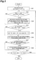
- Fig. 3 is a flowchart showing operation of the video predictive encoding/decoding method according to the present embodiment. Fig. 3 will be described below as the video encoding method. However, Fig. 3 is also applicable to the video decoding method.
- TR means display order information
- TR_DDR means display order information of a DDR picture
- TR_CUR means display order information of a processing target picture at a point of interest or at a time of processing the processing target picture such that the processing target picture is the current target picture
- RP means a state variable indicative of whether refreshment of the frame memory 104 is in standby.
- the reference pictures stored in the frame memory 107 that are set as unnecessary are only reference pictures with the display order information TR smaller than the display order information of the most recent DDR picture (TR_DDR).
- TR_DDR display order information of the most recent DDR picture
- the most recent DDR picture (or intra-frame predictive encoded picture) stored in the frame memory 104 is not set to be unnecessary.
- step 304 the operation proceeds to step 304 to check whether the current processing target picture is a DDR picture. It is assumed in the video predictive encoding device 100 that the encoding type information about the encoding type of the picture (DDR, inter-frame predictive encoding, or bidirectional predictive encoding) is supplied through the input terminal 113 in Fig. 1 from a control device (not shown).
- the condition is not satisfied in step 304, the operation proceeds to step 306.
- Step 306 is to obtain a reproduced picture corresponding to the processing target picture.
- the processing target picture is encoded to obtain compressed data that is compressed by the encoding method described with reference to Fig. 1 , and the compressed data is further decoded to obtain a reproduced picture (the reproduced picture corresponding to the processing target picture).
- the compressed data obtained by encoding is sent to the outside of the video predictive encoding device 100.
- the compressed data may be stored in a memory (not shown) that may be included in the video predictive encoding device 100.
- step 307 is to determine whether the reproduced picture corresponding to the processing target picture is to be used as a reference picture in a subsequent process. This determination is made based on the encoding type of the picture.
- a DDR picture, a unidirectional predictive encoded picture, and a specific bidirectional predictive encoded picture all are determined to be used as reference pictures, which are stored. It is, however, noted that the present invention is not limited to these encoding types or determination method.
- step 307 When it is determined in step 307 that the reproduced picture is not used as a reference picture, the reproduced picture is not stored in the frame memory 104 and the operation proceeds to step 309. On the other hand, if it is determined in step 307 that the reproduced picture is used as a reference picture, step 308 is carried out to store the reproduced picture in the frame memory 104, and then the operation proceeds to step 309.
- step 309 it is determined whether there is a next picture (unprocessed picture), and if there is a next picture, the operation returns to step 302 to repeat the processes of steps 302 to 308 for the next picture.
- the processes of steps 302 to 308 are repeatedly carried out until the last picture is processed. In this manner and, after completion of the processing for all the pictures, the processing of Fig. 3 is terminated.
- the frame memory 104 is refreshed at a time of processing a picture having display order information (TR) larger than TR_DDR (in fact, in step 303 before the process of step 306).
- the timing of refreshing the frame memory may be at any time after completion of the processing of the random access picture (the most recent DDR picture herein) when processing a picture with the display order information TR larger than TR_DDR, and may occur immediately after the process of step 306.
- Fig. 3 corresponds to the overall processing of the video predictive encoding device 100 in Fig. 1 , and, particularly, the processes of steps 302 to 305 are carried out by the frame memory management unit 114.
- step 301 further includes receipt of data of a compression-encoded picture (bitstream).
- bitstream The display order information and encoding type of a target picture are extracted from the data and the operations of steps 302 to 305 are carried out by the same method as above.
- step 306 carries out a process of decoding the compressed data of the target picture to restore the picture.
- the processes of step 307 and the subsequent steps are as described above. This processing corresponds to the overall processing of the video predictive decoding device 200 in Fig. 2 and, particularly, the processes of steps 302 to 305 are carried out by the frame memory management unit 209.
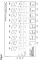
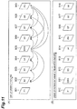
- Fig. 4 is a schematic diagram for explaining processing of the video predictive encoding/decoding method according to the present embodiment.
- identifiers written in frames of pictures 401 to 409 in Fig. 4 have the following meanings. Namely, "P” means a picture encoded by unidirectional prediction, "DDR” means a picture encoded as a DDR picture, and each of "B” and “b” means a picture encoded by bidirectional prediction.
- the pictures except for those indicated by uncapitalized b i.e., pictures indicated by capitalized B, P, and DDR all are assumed to be used as reference pictures.
- TR_DDR corresponding to the picture 401 may take any value, except a value stored by the preceding processing is set. Since the picture 401 indicated by capitalized P1 is used as a reference picture, it is stored into the frame memory.
- the pictures P1 and DDR5 are stored in the frame memory.
- RP 1
- the display order TR (n+3) of the picture 403 is smaller than TR_DDR (n+5) and the picture 403 is not a DDR picture; therefore, steps 302, 304 result in a negative determination and the picture 403 is encoded or decoded as it is (step 306). Since the picture 403 is used as a reference picture, it is stored in the frame memory.
- the reference pictures set as unnecessary at this time are only the reference pictures with the display order information TR smaller than that of the most recent DDR picture 402, except for the most recent DDR picture 402. Therefore, as shown in region 414 in Fig. 4 , storage areas of the picture P1 and the picture B3 are released in the frame memory, with the result that only the picture DDR5 remains stored.
- the picture 406, which is used as a reference picture is stored into the frame memory after completion of the processing of the picture 406, as shown in region 415 in Fig. 4 , and thereafter the refresh control of the frame memory is carried out in the same manner as above.
- the reference picture in the frame memory (picture P1 in Fig. 4 ) is not set as unnecessary, immediately after or immediately before the processing of the DDR picture 402 as described above, reference can be made to the picture P1 in the processing of the pictures 403, 404, and 405 processed after the DDR picture 402, and this contributes to an improvement in encoding efficiency. Since the most recent DDR picture 402 (picture DDR5) is not set as unnecessary in execution of refreshment of the frame memory after the processing of the DDR picture 402, the most recent DDR picture 402 (picture DDR5) can be used as a reference picture in the processing of the subsequent pictures 407, 408, and 409.
- the present embodiment makes use of the display order information included with each respective picture to set the timing of the memory refreshment that is carried out after the processing of the intra-frame predicted picture (DDR picture) serving as a point of random access.
- the timing of the memory refreshment is based on the display order information, thereby achieving efficient compression encoding of pictures before and after a random access picture. It also resolves the inconveniences associated with the defects of the conventional technology, as described below.
- the display order information is always includes with each respective picture, there is no need for transmission of new information (flag), which resolves the defect 2 of the conventional technology.
- pieces of display order information of the respective pictures constituting the video signal are also appropriately set so as to cause no malfunction, which resolves the defect 1 of the conventional technology.
- the timing of the memory refreshment according to the present invention is not limited to P pictures, and is independent of the encoding types of pictures (I pictures, P pictures, and B pictures), each picture is processed in an encoding type with the highest encoding efficiency, independent of the necessity of refreshment of the memory, which resolves the defect 3 of the conventional technology.
- the display order information of each picture is encoded as an "absolute value.”
- the display order information of each picture is encoded as "difference value,” in order to increase the encoding efficiency.
- difference value in order to increase the encoding efficiency.
- the below will describe the embodiment in which the display order information is encoded as "difference value,” as a modification example.
- Fig. 5 shows a flowchart of the modification example of the video predictive encoding/decoding method.
- the display order information thereof is encoded by any method. For example, a difference from the display order information of the DDR picture may be encoded, or a difference from the display order information of an immediately preceding picture in the encoding order may be encoded.
- Step 501 in Fig. 5 is to receive input data of a compression-encoded picture into the video predictive decoding device 200, and to extract from the data, a difference value (delta_TR) of the display order information of the target picture, and information about the encoding type of the picture.
- delta_TR difference value
- TR_DDR and RP are initialized to 0.
- Step 503 is to set the display order information TR_CUR of the current processing target picture to the sum of TR_DDR and delta_TR.
- step 504 is to check whether TR_CUR is larger than TR_DDR.
- the reference pictures set as unnecessary are only the reference pictures with the display order information TR smaller than the display order information of the most recent DDR picture (TR_DDR).
- the most recent DDR picture (or intra-frame predictive encoded picture) is not set as unnecessary.
- the operation proceeds to below-described step 507.
- the operation proceeds to step 506 to set TR_CUR to the sum of the display order information TR_PREV of a previously processed picture and delta_TR, and then the operation proceeds to step 507.
- Step 507 is to check whether the current processing target picture is a DDR picture.
- the video predictive decoding device 200 can obtain the encoding type information about the encoding type of the picture (DDR, inter-frame predictive encoding, or bidirectional predictive encoding) from the compression-encoded data input from the outside.
- the condition is not met in step 507, the operation proceeds to step 509.
- Step 509 is to obtain a reproduced picture corresponding to the processing target picture.
- the reproduced picture corresponding to the processing target picture is obtained by decoding the compressed data of the processing target picture by the decoding method described with reference to Fig. 2 .
- the reproduced picture obtained herein is sent, for example, external to the video predictive decoding device 200.
- step 510 is to determine whether the reproduced picture corresponding to the processing target picture is to be used as a reference picture in subsequent processing. This determination is made based on the encoding type of the picture. In this case, a DDR picture, a unidirectional predictive encoded picture, and a specific bidirectional predictive encoded picture all are determined to be reference pictures. It is, however, noted that the present invention is not limited to these encoding types or determination method.
- step 510 When it is determined in step 510 that the reproduced picture is not used as a reference picture, the operation proceeds to step 512 without storing the reproduced picture into the frame memory 207.
- step 511 is carried out to store the reproduced picture into the frame memory 207, and then the flow proceeds to step 512.
- Step 512 is to set TR_CUR to TR_PREV, for the subsequent process of step 506, and then the operation proceeds to step 513.
- Step 513 is to determine whether there is a next picture (unprocessed picture), and if there is a next picture, the operation returns to step 502 to repeat the processes of steps 502 to 512 for the next picture.
- the processes of steps 502 to 512 are repeatedly carried out up to the last picture in this manner and after completion of the processing for all the pictures, the processing of Fig. 5 is terminated.
- the frame memory is refreshed at a time when a picture having display order information TR that is larger than TR_DDR is processed(in fact, in step 505 before the process of step 509).
- the timing of refreshment of the frame memory may be any time after completion of the processing of the random access picture (the most recent DDR picture herein), when processing a picture with display order information TR that is larger than TR_DDR, and may be a time immediately after the process of step 509.
- Fig. 5 corresponds to the overall processing of the video predictive decoding device 200 in Fig. 2 and, particularly, steps 502 to 508 are carried out by the frame memory management unit 209.
- step 503 is to obtain delta_TR from the difference between TR_CUR and TR_DDR
- step 506 is to determine delta_TR from the difference between TR_CUR and TR_PREV, followed by entropy encoding
- step 509 is to encode the target picture and then decode the picture.
- This processing corresponds to the overall processing of the video predictive encoding device 100 in Fig. 1 and, particularly, the processes of steps 502 to 508 are carried out by the frame memory management unit 114.
- Fig. 6 is a schematic diagram for explaining the processing of the video predictive encoding/decoding method according to the modification example embodiment.
- Pictures 601 to 609 shown in Fig. 6 are some of a series of pictures constituting a video sequence and show the same processing as the pictures 401 to 409 described with reference to Fig. 4 .
- Fig. 6 includes delta_TR shown in region 621, in addition to the regions of Fig. 4 . As seen from region 621, determination of delta_TR is different depending upon the value of RP at a start of the encoding process of a target picture (the RP value of a previous picture).
- delta_TR is obtained as a difference value between TR of each picture and TR_DDR
- delta_TR is obtained as a difference value between TR of a target picture and TR of a picture immediately before the target picture.
- TR of picture 607 is subtracted from TR of picture 606 to obtain delta_TR of picture 607.
- the display order information TR is restored from the difference value delta_TR in the decoding process of each picture, the display order information TR is restored by adding the difference value delta_TR obtained by decoding the compressed data of the difference value, to TR_DDR.
- the processing thereafter is the same as that in Fig. 4 and is thus omitted herein.
- the difference value delta_TR between the display order information TR of the current picture and the display order information TR_DDR of the DDR picture may be encoded, instead of encoding the display order information TR of the current picture itself, to thereby correctly decode the timing of refreshment of the frame memory. For this reason, even if a picture waiting for refreshment of the frame memory is lost, malfunction can be avoided, achieving an effect of high error resistance.
- the difference value delta_TR may be encoded for at least one picture which includes a picture for which the display order information TR is larger than the TR_DDR (picture 606 in Fig. 6 ), and which comes after the random access picture (the most recent DDR picture herein),.
- the difference value delta_TR between the display order information TR of the pertinent picture and the display order information TR_DDR of the DDR picture may be encoded, instead of encoding the display order information TR of the pertinent picture itself.
- the invention of the video predictive encoding device can also be interpreted as the invention of a video predictive encoding program for controlling a computer to function as the video predictive encoding device.
- the invention of the video predictive decoding device can also be interpreted as the invention of a video predictive decoding program for controlling a computer to function as the video predictive decoding device.
- the video predictive encoding program and the video predictive decoding program are provided, for example, as stored in a recording medium.
- recording media include recording media such as flexible disks, CD-ROMs, and DVDs, or recording media such as ROMs, or semiconductor memories or the like.
- Fig. 9 shows modules of the video predictive encoding program for controlling a computer to function as the video predictive encoding device.
- the video predictive encoding program P100 is provided with input module P101, encoding module P102, restoration module P103, picture storage module P104, and memory management module P105.
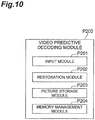
- Fig. 10 shows modules of the video predictive decoding program for controlling a computer to function as the video predictive decoding device.
- the video predictive decoding program P200 is provided with input module P201, restoration module P202, picture storage module P203, and memory management module P204.
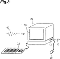
- the video predictive encoding program P100 and the video predictive decoding program P200 configured as described above can be stored in a recording medium 10 shown in Fig. 8 and are executed by computer 30 described below.
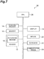
- Fig. 7 is a drawing showing a hardware configuration of a computer for executing a program recorded in a recording medium
- Fig. 8 is a schematic view of a computer for executing a program stored in a recording medium.
- the computer may be, a DVD player, a set-top box, a cell phone, etc. which are provided with a CPU and are configured to perform processing and control by software.
- the computer 30 can be provided with a reading device 12 such as a flexible disk drive unit, a CD-ROM drive unit, or a DVD drive unit, a working memory (RAM) 14 in which an operating system is resident, a memory 16 for storing programs and data, which may also or alternatively be stored elsewhere such as in the recording medium 10, a monitor unit 18 like a display, a mouse 20 and a keyboard 22 as input devices, a communication device 24 for transmission and reception of data or the like, and a CPU 26 for controlling execution of programs.
- a reading device 12 such as a flexible disk drive unit, a CD-ROM drive unit, or a DVD drive unit
- RAM working memory
- a memory 16 for storing programs and data, which may also or alternatively be stored elsewhere
- a monitor unit 18 like a display
- a mouse 20 and a keyboard 22 as input devices
- a communication device 24 for transmission and reception of data or the like
- a CPU 26 for controlling execution of programs.
- the computer 30 when the recording medium 10 is put into the reading device 12, the computer 30 becomes accessible to the video predictive encoding program stored in the recording medium 10, through the reading device 12 and becomes able to operate as the video predictive encoding device according to the present invention, based on the video predictive encoding program.
- the computer 30 when the recording medium 10 is put into the reading device 12, the computer 30 becomes accessible to the video predictive decoding program stored in the recording medium 10, through the reading device 12 and becomes able to operate as the video predictive decoding device according to the present invention, based on the video predictive decoding program.
- the video predictive encoding program or the video predictive decoding program may be provided in the form of computer data signal 40 superimposed on a carrier wave, through a network.
- the computer 30 can execute the program after the video predictive encoding program or the video predictive decoding program received by the communication device 24 is stored into the memory 16.
- 10 recording medium; 30: computer; 100: video predictive encoding device; 101: input terminal; 102: block divider; 103: predicted signal generator; 104: frame memory; 105: subtracter; 106: transformer; 107: quantizer; 108: de-quantizer; 109: inverse-transformer; 110: adder; 111: entropy encoder; 112: output terminal; 113: input terminal; 114: frame memory management unit; 200: video predictive decoding device; 201: input terminal; 202: data analyzer; 203: de-quantizer; 204: inverse-transformer; 205: adder; 206: output terminal; 207: frame memory; 208: predicted signal generator; 209: frame memory management unit; P100: video predictive encoding program; P101: input module; P102: encoding module; P103: restoration module; P104: picture storage module; P105: memory management module; P200: video predictive decoding program; P201: input module; P202: restoration module; P203: picture storage
Landscapes
- Engineering & Computer Science (AREA)
- Multimedia (AREA)
- Signal Processing (AREA)
- Compression Or Coding Systems Of Tv Signals (AREA)
- Image Processing (AREA)
Priority Applications (5)
| Application Number | Priority Date | Filing Date | Title |
|---|---|---|---|
| PL15169622T PL2942965T3 (pl) | 2010-03-17 | 2011-03-14 | Urządzenie do predykcyjnego kodowania obrazu ruchomego, sposób predykcyjnego kodowania obrazu ruchomego, program do predykcyjnego kodowania obrazu ruchomego, urządzenie do predykcyjnego dekodowania obrazu ruchomego, sposób predykcyjnego dekodowania obrazu ruchomego i program do predykcyjnego dekodowania obrazu ruchomego |
| EP17199102.9A EP3300369A1 (en) | 2010-03-17 | 2011-03-14 | Moving image prediction decoding device, moving image prediction decoding method |
| NO15169622A NO2942965T3 (ja) | 2010-03-17 | 2011-03-14 | |
| EP15169622.6A EP2942965B1 (en) | 2010-03-17 | 2011-03-14 | Moving image prediction encoding device, moving image prediction encoding method, moving image prediction encoding program, moving image prediction decoding device, moving image prediction decoding method, and moving image prediction decoding program |
| PL11756230T PL2549758T3 (pl) | 2010-03-17 | 2011-03-14 | Urządzenie do predykcyjnego kodowania obrazu ruchomego, sposób predykcyjnego kodowania obrazu ruchomego, program do predykcyjnego kodowania obrazu ruchomego, urządzenie do predykcyjnego dekodowania obrazu ruchomego, sposób predykcyjnego dekodowania obrazu ruchomego i program do predykcyjnego dekodowania obrazu ruchomego |
Applications Claiming Priority (2)
| Application Number | Priority Date | Filing Date | Title |
|---|---|---|---|
| JP2010061337A JP2011199396A (ja) | 2010-03-17 | 2010-03-17 | 動画像予測符号化装置、動画像予測符号化方法、動画像予測符号化プログラム、動画像予測復号装置、動画像予測復号方法、及び動画像予測復号プログラム |
| PCT/JP2011/055915 WO2011115045A1 (ja) | 2010-03-17 | 2011-03-14 | 動画像予測符号化装置、動画像予測符号化方法、動画像予測符号化プログラム、動画像予測復号装置、動画像予測復号方法、及び動画像予測復号プログラム |
Related Child Applications (4)
| Application Number | Title | Priority Date | Filing Date |
|---|---|---|---|
| EP17199102.9A Division-Into EP3300369A1 (en) | 2010-03-17 | 2011-03-14 | Moving image prediction decoding device, moving image prediction decoding method |
| EP17199102.9A Division EP3300369A1 (en) | 2010-03-17 | 2011-03-14 | Moving image prediction decoding device, moving image prediction decoding method |
| EP15169622.6A Division-Into EP2942965B1 (en) | 2010-03-17 | 2011-03-14 | Moving image prediction encoding device, moving image prediction encoding method, moving image prediction encoding program, moving image prediction decoding device, moving image prediction decoding method, and moving image prediction decoding program |
| EP15169622.6A Division EP2942965B1 (en) | 2010-03-17 | 2011-03-14 | Moving image prediction encoding device, moving image prediction encoding method, moving image prediction encoding program, moving image prediction decoding device, moving image prediction decoding method, and moving image prediction decoding program |
Publications (3)
| Publication Number | Publication Date |
|---|---|
| EP2549758A1 EP2549758A1 (en) | 2013-01-23 |
| EP2549758A4 EP2549758A4 (en) | 2015-11-25 |
| EP2549758B1 true EP2549758B1 (en) | 2017-12-06 |
Family
ID=44649138
Family Applications (3)
| Application Number | Title | Priority Date | Filing Date |
|---|---|---|---|
| EP11756230.6A Active EP2549758B1 (en) | 2010-03-17 | 2011-03-14 | Moving image prediction encoding device, moving image prediction encoding method, moving image prediction encoding program, moving image prediction decoding device, moving image prediction decoding method, and moving image prediction decoding program |
| EP15169622.6A Active EP2942965B1 (en) | 2010-03-17 | 2011-03-14 | Moving image prediction encoding device, moving image prediction encoding method, moving image prediction encoding program, moving image prediction decoding device, moving image prediction decoding method, and moving image prediction decoding program |
| EP17199102.9A Withdrawn EP3300369A1 (en) | 2010-03-17 | 2011-03-14 | Moving image prediction decoding device, moving image prediction decoding method |
Family Applications After (2)
| Application Number | Title | Priority Date | Filing Date |
|---|---|---|---|
| EP15169622.6A Active EP2942965B1 (en) | 2010-03-17 | 2011-03-14 | Moving image prediction encoding device, moving image prediction encoding method, moving image prediction encoding program, moving image prediction decoding device, moving image prediction decoding method, and moving image prediction decoding program |
| EP17199102.9A Withdrawn EP3300369A1 (en) | 2010-03-17 | 2011-03-14 | Moving image prediction decoding device, moving image prediction decoding method |
Country Status (17)
| Country | Link |
|---|---|
| US (6) | US9113171B2 (ja) |
| EP (3) | EP2549758B1 (ja) |
| JP (1) | JP2011199396A (ja) |
| KR (3) | KR101747195B1 (ja) |
| CN (3) | CN104768020B (ja) |
| AU (9) | AU2011228218B2 (ja) |
| BR (1) | BR112012023322B1 (ja) |
| CA (8) | CA3041891C (ja) |
| ES (2) | ES2655416T3 (ja) |
| MX (1) | MX2012010614A (ja) |
| NO (2) | NO2942965T3 (ja) |
| PL (2) | PL2942965T3 (ja) |
| PT (2) | PT2549758T (ja) |
| RU (6) | RU2568310C2 (ja) |
| SG (2) | SG10201501390XA (ja) |
| TW (7) | TWI670965B (ja) |
| WO (1) | WO2011115045A1 (ja) |
Families Citing this family (15)
| Publication number | Priority date | Publication date | Assignee | Title |
|---|---|---|---|---|
| JP2011199396A (ja) | 2010-03-17 | 2011-10-06 | Ntt Docomo Inc | 動画像予測符号化装置、動画像予測符号化方法、動画像予測符号化プログラム、動画像予測復号装置、動画像予測復号方法、及び動画像予測復号プログラム |
| DK3267681T3 (en) * | 2011-07-02 | 2018-12-17 | Samsung Electronics Co Ltd | DEVICE FOR MULTIPLEXING AND DEMULTIPLEXING VIDEO DATA TO IDENTIFY THE REPRODUCTION MODE OF VIDEODATA. |
| US9131245B2 (en) | 2011-09-23 | 2015-09-08 | Qualcomm Incorporated | Reference picture list construction for video coding |
| JP5698644B2 (ja) * | 2011-10-18 | 2015-04-08 | 株式会社Nttドコモ | 動画像予測符号化方法、動画像予測符号化装置、動画像予測符号化プログラム、動画像予測復号方法、動画像予測復号装置及び動画像予測復号プログラム |
| US9432694B2 (en) | 2012-03-06 | 2016-08-30 | Apple Inc. | Signal shaping techniques for video data that is susceptible to banding artifacts |
| JP6045222B2 (ja) * | 2012-06-28 | 2016-12-14 | 株式会社Nttドコモ | 動画像予測復号装置、方法及びプログラム |
| MY190544A (en) * | 2012-06-29 | 2022-04-27 | Velos Media Int Ltd | Decoding device and decoding method |
| GB2516425B (en) * | 2013-07-17 | 2015-12-30 | Gurulogic Microsystems Oy | Encoder and decoder, and method of operation |
| KR102133978B1 (ko) | 2013-11-13 | 2020-07-14 | 삼성전자주식회사 | 압축 데이터를 이용하여 패널 셀프 리프레쉬를 수행할 수 있는 타이밍 컨트롤러, 이의 동작 방법, 및 상기 타이밍 컨트롤러를 포함하는 데이터 처리 시스템 |
| CN107113422B (zh) * | 2015-11-06 | 2020-08-25 | 微软技术许可有限责任公司 | 一种用于视频编码和解码的参考图片管理的计算机系统 |
| JP6641344B2 (ja) * | 2017-12-05 | 2020-02-05 | 三菱電機株式会社 | 符号化装置 |
| GB2619631B (en) * | 2019-03-20 | 2024-04-03 | V Nova Int Ltd | Low complexity enhancement video coding |
| CN111124337B (zh) * | 2019-12-17 | 2023-08-01 | 西安万像电子科技有限公司 | 图像显示方法及系统 |
| EP4118835A4 (en) * | 2020-03-31 | 2023-05-10 | Beijing Dajia Internet Information Technology Co., Ltd. | HIGH LEVEL SYNTAX METHODS AND DEVICES IN VIDEO CODING |
| WO2021203039A1 (en) * | 2020-04-03 | 2021-10-07 | Beijing Dajia Internet Information Technology Co., Ltd. | Methods and devices for high-level syntax in video coding |
Family Cites Families (52)
| Publication number | Priority date | Publication date | Assignee | Title |
|---|---|---|---|---|
| RU2161377C2 (ru) * | 1992-12-04 | 2000-12-27 | Сони Корпорейшн | Устройство и способ подготовки к записи на носителе информации кодируемого с переменным параметром сигнала, устройство и способ последовательного сигнала, способ воспроизведения шаблонов с носителя информации |
| US6950469B2 (en) * | 2001-09-17 | 2005-09-27 | Nokia Corporation | Method for sub-pixel value interpolation |
| BRPI0216048B1 (pt) * | 2001-10-17 | 2018-09-25 | Matsushita Electric Ind Co Ltd | método e aparelho de codificação de figuras móveis |
| CN101656882B (zh) * | 2001-11-06 | 2013-04-17 | 松下电器产业株式会社 | 运动图像编码方法及运动图像解码方法 |
| JP4355156B2 (ja) * | 2002-04-16 | 2009-10-28 | パナソニック株式会社 | 画像復号化方法及び画像復号化装置 |
| EP2278816B1 (en) * | 2002-07-11 | 2013-04-24 | Panasonic Corporation | Post-decoder buffer management for an H.264-SVC MPEG bitstream. |
| JP2005533444A (ja) * | 2002-07-16 | 2005-11-04 | ノキア コーポレイション | 画像符号化におけるランダム・アクセス及び段階的画像更新に対する方法 |
| TWI249356B (en) * | 2002-11-06 | 2006-02-11 | Nokia Corp | Picture buffering for prediction references and display |
| CN1739299A (zh) * | 2003-01-20 | 2006-02-22 | 松下电器产业株式会社 | 图像编码方法 |
| AU2004214313B2 (en) * | 2003-02-18 | 2010-05-20 | Nokia Technologies Oy | Picture coding method |
| JP2004260236A (ja) | 2003-02-24 | 2004-09-16 | Matsushita Electric Ind Co Ltd | 動画像の符号化方法および復号化方法 |
| CN101771881B (zh) * | 2003-03-03 | 2012-08-29 | 松下电器产业株式会社 | 编码装置、编码方法、解码装置、解码方法及记录方法 |
| EP1496707A1 (en) | 2003-07-09 | 2005-01-12 | Matsushita Electric Industrial Co., Ltd. | Encoding and decoding of video images with delayed reference picture refresh |
| JP4591657B2 (ja) * | 2003-12-22 | 2010-12-01 | キヤノン株式会社 | 動画像符号化装置及びその制御方法、プログラム |
| EP1774779A2 (en) * | 2004-07-01 | 2007-04-18 | QUALCOMM Incorporated | Method and apparatus for using frame rate up conversion techniques in scalable video coding |
| JP4638874B2 (ja) * | 2004-08-11 | 2011-02-23 | 株式会社日立製作所 | 符号化ストリーム記録媒体、及び画像符号化装置 |
| RU2287909C2 (ru) * | 2004-12-15 | 2006-11-20 | Московский технический университет связи и информатики | Способ преобразования цифрового сигнала изображения и устройство для его реализации |
| WO2006075635A1 (ja) * | 2005-01-17 | 2006-07-20 | Matsushita Electric Industrial Co., Ltd. | 画像復号化方法 |
| BRPI0606627A2 (pt) * | 2005-01-19 | 2009-07-07 | Thomson Licensing | método e aparelho para codificação paralela em tempo real |
| CA2597227A1 (en) * | 2005-02-09 | 2006-08-17 | March Networks Corporation | Method and system for low-subband content discrimination |
| JP2006246277A (ja) * | 2005-03-07 | 2006-09-14 | Pioneer Electronic Corp | 再符号化装置、再符号化方法、および再符号化用プログラム |
| US8036281B2 (en) * | 2005-06-01 | 2011-10-11 | Canon Kabushiki Kaisha | Image coding apparatus and image coding method |
| RU2368095C1 (ru) * | 2005-07-22 | 2009-09-20 | Мицубиси Электрик Корпорейшн | Кодер изображения и декодер изображения, способ кодирования изображения и способ декодирования изображения, программа кодирования изображения и программа декодирования изображения и компьютерно-считываемый носитель записи, на котором записана программа кодирования изображения, и компьютерно-считываемый носитель записи, на котором записана программа декодирования изображения |
| WO2007063808A1 (ja) * | 2005-11-30 | 2007-06-07 | Kabushiki Kaisha Toshiba | 画像符号化/画像復号化方法及び画像符号化/画像復号化装置 |
| US8155185B2 (en) * | 2005-12-05 | 2012-04-10 | Canon Kabushiki Kaisha | Image coding apparatus and method |
| CN101346998B (zh) * | 2006-01-05 | 2012-01-11 | 日本电信电话株式会社 | 视频编码方法及解码方法、其装置 |
| TW200806040A (en) * | 2006-01-05 | 2008-01-16 | Nippon Telegraph & Telephone | Video encoding method and decoding method, apparatuses therefor, programs therefor, and storage media for storing the programs |
| WO2007080223A1 (en) * | 2006-01-10 | 2007-07-19 | Nokia Corporation | Buffering of decoded reference pictures |
| US20080165860A1 (en) * | 2006-08-31 | 2008-07-10 | Zohair Sahraoui | H.264 Data processing |
| EP2087738B1 (en) * | 2006-10-13 | 2016-04-13 | Thomson Licensing | Method for reference picture management involving multiview video coding |
| CN101563927A (zh) * | 2006-12-21 | 2009-10-21 | 汤姆森许可贸易公司 | 用于对视频图像的块进行解码的方法 |
| JP2008193627A (ja) * | 2007-01-12 | 2008-08-21 | Mitsubishi Electric Corp | 画像符号化装置、画像復号装置、および画像符号化方法、画像復号方法 |
| JP5023739B2 (ja) * | 2007-02-28 | 2012-09-12 | ソニー株式会社 | 画像情報符号化装置及び符号化方法 |
| EP1983759A1 (en) * | 2007-04-19 | 2008-10-22 | Matsushita Electric Industrial Co., Ltd. | Estimation of separable adaptive interpolation filters for hybrid video coding |
| JP5188875B2 (ja) * | 2007-06-04 | 2013-04-24 | 株式会社エヌ・ティ・ティ・ドコモ | 画像予測符号化装置、画像予測復号装置、画像予測符号化方法、画像予測復号方法、画像予測符号化プログラム、及び画像予測復号プログラム |
| US8265144B2 (en) * | 2007-06-30 | 2012-09-11 | Microsoft Corporation | Innovations in video decoder implementations |
| US9648325B2 (en) * | 2007-06-30 | 2017-05-09 | Microsoft Technology Licensing, Llc | Video decoding implementations for a graphics processing unit |
| US8699808B2 (en) * | 2007-10-15 | 2014-04-15 | Chih-Ta Star Sung | Method and apparatus of temporary image frame compression |
| FR2924296B1 (fr) * | 2007-11-28 | 2010-05-28 | Canon Kk | Procede et dispositif de traitement d'un flux de donnees multimedia hierarchique transmis sur un reseau avec perte |
| JP5056560B2 (ja) * | 2008-03-17 | 2012-10-24 | 富士通株式会社 | 符号化装置、復号化装置、符号化方法および復号化方法 |
| JP4935746B2 (ja) * | 2008-04-07 | 2012-05-23 | 富士通株式会社 | 動画像符号化装置、動画像復号化装置及びその符号化、復号化方法 |
| JP2009296078A (ja) | 2008-06-03 | 2009-12-17 | Victor Co Of Japan Ltd | 符号化データ再生装置、符号化データ再生方法、および符号化データ再生プログラム |
| EP2157799A1 (en) * | 2008-08-18 | 2010-02-24 | Panasonic Corporation | Interpolation filter with local adaptation based on block edges in the reference frame |
| JP2010245970A (ja) * | 2009-04-08 | 2010-10-28 | Sony Corp | 再生装置、再生方法、およびプログラム |
| JP4962525B2 (ja) * | 2009-04-08 | 2012-06-27 | ソニー株式会社 | 再生装置、再生方法、およびプログラム |
| US8976871B2 (en) * | 2009-09-16 | 2015-03-10 | Qualcomm Incorporated | Media extractor tracks for file format track selection |
| JP2011199396A (ja) | 2010-03-17 | 2011-10-06 | Ntt Docomo Inc | 動画像予測符号化装置、動画像予測符号化方法、動画像予測符号化プログラム、動画像予測復号装置、動画像予測復号方法、及び動画像予測復号プログラム |
| KR101750495B1 (ko) * | 2010-04-16 | 2017-06-27 | 에스케이텔레콤 주식회사 | 인터 예측 방법 및 그 인터 예측 방법을 이용한 동영상 부호화/복호화 방법 |
| US9516379B2 (en) * | 2011-03-08 | 2016-12-06 | Qualcomm Incorporated | Buffer management in video codecs |
| KR20140057533A (ko) * | 2011-07-15 | 2014-05-13 | 텔레폰악티에볼라겟엘엠에릭슨(펍) | 랜덤 액세스 픽처를 청정하게 하기 위해 가장 낮은 계층 식별을 할당하기 위한 인코더 및 방법 |
| US9654802B2 (en) | 2012-09-24 | 2017-05-16 | Qualcomm Incorporated | Sequence level flag for sub-picture level coded picture buffer parameters |
| US10375412B2 (en) * | 2014-01-13 | 2019-08-06 | Samsung Electronics Co., Ltd. | Multi-layer video encoding method and apparatus, and multi-layer video decoding method and apparatus |
-
2010
- 2010-03-17 JP JP2010061337A patent/JP2011199396A/ja active Pending
-
2011
- 2011-03-14 CA CA3041891A patent/CA3041891C/en active Active
- 2011-03-14 ES ES11756230.6T patent/ES2655416T3/es active Active
- 2011-03-14 CA CA3169174A patent/CA3169174A1/en active Pending
- 2011-03-14 KR KR1020167012926A patent/KR101747195B1/ko active IP Right Grant
- 2011-03-14 RU RU2012144029/08A patent/RU2568310C2/ru active
- 2011-03-14 CA CA3081303A patent/CA3081303C/en active Active
- 2011-03-14 RU RU2015122410/08A patent/RU2601134C2/ru active
- 2011-03-14 EP EP11756230.6A patent/EP2549758B1/en active Active
- 2011-03-14 CN CN201510165668.6A patent/CN104768020B/zh active Active
- 2011-03-14 EP EP15169622.6A patent/EP2942965B1/en active Active
- 2011-03-14 PL PL15169622T patent/PL2942965T3/pl unknown
- 2011-03-14 PL PL11756230T patent/PL2549758T3/pl unknown
- 2011-03-14 CA CA3094541A patent/CA3094541C/en active Active
- 2011-03-14 NO NO15169622A patent/NO2942965T3/no unknown
- 2011-03-14 CA CA2935201A patent/CA2935201C/en active Active
- 2011-03-14 CA CA3009695A patent/CA3009695C/en active Active
- 2011-03-14 KR KR1020177015372A patent/KR101867461B1/ko active IP Right Grant
- 2011-03-14 PT PT117562306T patent/PT2549758T/pt unknown
- 2011-03-14 SG SG10201501390XA patent/SG10201501390XA/en unknown
- 2011-03-14 SG SG2012068334A patent/SG184079A1/en unknown
- 2011-03-14 BR BR112012023322A patent/BR112012023322B1/pt active IP Right Grant
- 2011-03-14 CA CA3094540A patent/CA3094540C/en active Active
- 2011-03-14 EP EP17199102.9A patent/EP3300369A1/en not_active Withdrawn
- 2011-03-14 CN CN201180013583.6A patent/CN102792696B/zh active Active
- 2011-03-14 MX MX2012010614A patent/MX2012010614A/es active IP Right Grant
- 2011-03-14 PT PT151696226T patent/PT2942965T/pt unknown
- 2011-03-14 AU AU2011228218A patent/AU2011228218B2/en active Active
- 2011-03-14 WO PCT/JP2011/055915 patent/WO2011115045A1/ja active Application Filing
- 2011-03-14 KR KR1020127027048A patent/KR101640872B1/ko active IP Right Grant
- 2011-03-14 CA CA2793168A patent/CA2793168C/en active Active
- 2011-03-14 NO NO11756230A patent/NO2549758T3/no unknown
- 2011-03-14 CN CN201510603845.4A patent/CN105187842B/zh active Active
- 2011-03-14 ES ES15169622.6T patent/ES2655919T3/es active Active
- 2011-03-17 TW TW107140720A patent/TWI670965B/zh active
- 2011-03-17 TW TW100109131A patent/TWI479895B/zh active
- 2011-03-17 TW TW108121288A patent/TWI678913B/zh active
- 2011-03-17 TW TW107104188A patent/TWI650002B/zh active
- 2011-03-17 TW TW108133969A patent/TWI691198B/zh active
- 2011-03-17 TW TW104100275A patent/TWI611686B/zh active
- 2011-03-17 TW TW106136961A patent/TWI619373B/zh active
-
2012
- 2012-09-14 US US13/618,066 patent/US9113171B2/en active Active
-
2015
- 2015-08-10 US US14/822,657 patent/US10178407B2/en active Active
-
2016
- 2016-01-13 AU AU2016200188A patent/AU2016200188B2/en active Active
- 2016-08-12 RU RU2016133267A patent/RU2628260C1/ru active
-
2017
- 2017-08-02 RU RU2017127527A patent/RU2652438C1/ru active
-
2018
- 2018-03-27 AU AU2018202169A patent/AU2018202169B2/en active Active
- 2018-03-27 AU AU2018202171A patent/AU2018202171B2/en active Active
- 2018-03-27 AU AU2018202170A patent/AU2018202170B2/en active Active
- 2018-03-28 RU RU2018111019A patent/RU2676408C1/ru active
- 2018-12-07 US US16/213,660 patent/US10298953B2/en active Active
- 2018-12-07 US US16/213,684 patent/US10390042B2/en active Active
- 2018-12-13 RU RU2018144129A patent/RU2690220C1/ru active
-
2019
- 2019-04-05 US US16/376,966 patent/US10715829B2/en active Active
- 2019-06-28 US US16/457,066 patent/US10567794B2/en active Active
- 2019-12-11 AU AU2019280003A patent/AU2019280003B2/en active Active
- 2019-12-11 AU AU2019280009A patent/AU2019280009B2/en active Active
-
2021
- 2021-02-05 AU AU2021200759A patent/AU2021200759B2/en active Active
- 2021-11-09 AU AU2021266226A patent/AU2021266226B2/en active Active
Non-Patent Citations (1)
| Title |
|---|
| None * |
Also Published As
Similar Documents
| Publication | Publication Date | Title |
|---|---|---|
| AU2021266226B2 (en) | Moving image prediction encoding device, moving image prediction encoding method, moving image prediction encoding program, moving image prediction decoding device, moving image prediction decoding method, and moving image prediction decoding program |
Legal Events
| Date | Code | Title | Description |
|---|---|---|---|
| PUAI | Public reference made under article 153(3) epc to a published international application that has entered the european phase |
Free format text: ORIGINAL CODE: 0009012 |
|
| 17P | Request for examination filed |
Effective date: 20120918 |
|
| AK | Designated contracting states |
Kind code of ref document: A1 Designated state(s): AL AT BE BG CH CY CZ DE DK EE ES FI FR GB GR HR HU IE IS IT LI LT LU LV MC MK MT NL NO PL PT RO RS SE SI SK SM TR |
|
| DAX | Request for extension of the european patent (deleted) | ||
| REG | Reference to a national code |
Ref country code: DE Ref legal event code: R079 Ref document number: 602011043967 Country of ref document: DE Free format text: PREVIOUS MAIN CLASS: H04N0007320000 Ipc: H04N0019610000 |
|
| RA4 | Supplementary search report drawn up and despatched (corrected) |
Effective date: 20151022 |
|
| RIC1 | Information provided on ipc code assigned before grant |
Ipc: H04N 19/573 20140101ALI20151016BHEP Ipc: H04N 19/423 20140101ALI20151016BHEP Ipc: H04N 19/107 20140101ALI20151016BHEP Ipc: H04N 19/61 20140101AFI20151016BHEP |
|
| 17Q | First examination report despatched |
Effective date: 20160808 |
|
| GRAP | Despatch of communication of intention to grant a patent |
Free format text: ORIGINAL CODE: EPIDOSNIGR1 |
|
| INTG | Intention to grant announced |
Effective date: 20170630 |
|
| RIN1 | Information on inventor provided before grant (corrected) |
Inventor name: SUZUKI, YOSHINORI Inventor name: BOON, CHOONG SENG Inventor name: TAN, THIOW KENG Inventor name: FUJIBAYASHI, AKIRA |
|
| GRAS | Grant fee paid |
Free format text: ORIGINAL CODE: EPIDOSNIGR3 |
|
| GRAA | (expected) grant |
Free format text: ORIGINAL CODE: 0009210 |
|
| AK | Designated contracting states |
Kind code of ref document: B1 Designated state(s): AL AT BE BG CH CY CZ DE DK EE ES FI FR GB GR HR HU IE IS IT LI LT LU LV MC MK MT NL NO PL PT RO RS SE SI SK SM TR |
|
| REG | Reference to a national code |
Ref country code: GB Ref legal event code: FG4D |
|
| REG | Reference to a national code |
Ref country code: AT Ref legal event code: REF Ref document number: 953371 Country of ref document: AT Kind code of ref document: T Effective date: 20171215 Ref country code: CH Ref legal event code: EP |
|
| REG | Reference to a national code |
Ref country code: IE Ref legal event code: FG4D |
|
| REG | Reference to a national code |
Ref country code: RO Ref legal event code: EPE Ref country code: DE Ref legal event code: R096 Ref document number: 602011043967 Country of ref document: DE |
|
| REG | Reference to a national code |
Ref country code: PT Ref legal event code: SC4A Ref document number: 2549758 Country of ref document: PT Date of ref document: 20180115 Kind code of ref document: T Free format text: AVAILABILITY OF NATIONAL TRANSLATION Effective date: 20180108 |
|
| REG | Reference to a national code |
Ref country code: NL Ref legal event code: FP |
|
| REG | Reference to a national code |
Ref country code: SE Ref legal event code: TRGR |
|
| REG | Reference to a national code |
Ref country code: ES Ref legal event code: FG2A Ref document number: 2655416 Country of ref document: ES Kind code of ref document: T3 Effective date: 20180220 |
|
| REG | Reference to a national code |
Ref country code: NO Ref legal event code: T2 Effective date: 20171206 |
|
| REG | Reference to a national code |
Ref country code: FR Ref legal event code: PLFP Year of fee payment: 8 |
|
| REG | Reference to a national code |
Ref country code: LT Ref legal event code: MG4D |
|
| PG25 | Lapsed in a contracting state [announced via postgrant information from national office to epo] |
Ref country code: LT Free format text: LAPSE BECAUSE OF FAILURE TO SUBMIT A TRANSLATION OF THE DESCRIPTION OR TO PAY THE FEE WITHIN THE PRESCRIBED TIME-LIMIT Effective date: 20171206 Ref country code: FI Free format text: LAPSE BECAUSE OF FAILURE TO SUBMIT A TRANSLATION OF THE DESCRIPTION OR TO PAY THE FEE WITHIN THE PRESCRIBED TIME-LIMIT Effective date: 20171206 |
|
| REG | Reference to a national code |
Ref country code: AT Ref legal event code: MK05 Ref document number: 953371 Country of ref document: AT Kind code of ref document: T Effective date: 20171206 |
|
| PG25 | Lapsed in a contracting state [announced via postgrant information from national office to epo] |
Ref country code: BG Free format text: LAPSE BECAUSE OF FAILURE TO SUBMIT A TRANSLATION OF THE DESCRIPTION OR TO PAY THE FEE WITHIN THE PRESCRIBED TIME-LIMIT Effective date: 20180306 Ref country code: GR Free format text: LAPSE BECAUSE OF FAILURE TO SUBMIT A TRANSLATION OF THE DESCRIPTION OR TO PAY THE FEE WITHIN THE PRESCRIBED TIME-LIMIT Effective date: 20180307 Ref country code: RS Free format text: LAPSE BECAUSE OF FAILURE TO SUBMIT A TRANSLATION OF THE DESCRIPTION OR TO PAY THE FEE WITHIN THE PRESCRIBED TIME-LIMIT Effective date: 20171206 Ref country code: LV Free format text: LAPSE BECAUSE OF FAILURE TO SUBMIT A TRANSLATION OF THE DESCRIPTION OR TO PAY THE FEE WITHIN THE PRESCRIBED TIME-LIMIT Effective date: 20171206 Ref country code: HR Free format text: LAPSE BECAUSE OF FAILURE TO SUBMIT A TRANSLATION OF THE DESCRIPTION OR TO PAY THE FEE WITHIN THE PRESCRIBED TIME-LIMIT Effective date: 20171206 |
|
| PG25 | Lapsed in a contracting state [announced via postgrant information from national office to epo] |
Ref country code: EE Free format text: LAPSE BECAUSE OF FAILURE TO SUBMIT A TRANSLATION OF THE DESCRIPTION OR TO PAY THE FEE WITHIN THE PRESCRIBED TIME-LIMIT Effective date: 20171206 |
|
| PG25 | Lapsed in a contracting state [announced via postgrant information from national office to epo] |
Ref country code: SM Free format text: LAPSE BECAUSE OF FAILURE TO SUBMIT A TRANSLATION OF THE DESCRIPTION OR TO PAY THE FEE WITHIN THE PRESCRIBED TIME-LIMIT Effective date: 20171206 Ref country code: AT Free format text: LAPSE BECAUSE OF FAILURE TO SUBMIT A TRANSLATION OF THE DESCRIPTION OR TO PAY THE FEE WITHIN THE PRESCRIBED TIME-LIMIT Effective date: 20171206 |
|
| REG | Reference to a national code |
Ref country code: DE Ref legal event code: R097 Ref document number: 602011043967 Country of ref document: DE |
|
| PLBE | No opposition filed within time limit |
Free format text: ORIGINAL CODE: 0009261 |
|
| STAA | Information on the status of an ep patent application or granted ep patent |
Free format text: STATUS: NO OPPOSITION FILED WITHIN TIME LIMIT |
|
| 26N | No opposition filed |
Effective date: 20180907 |
|
| PG25 | Lapsed in a contracting state [announced via postgrant information from national office to epo] |
Ref country code: MC Free format text: LAPSE BECAUSE OF FAILURE TO SUBMIT A TRANSLATION OF THE DESCRIPTION OR TO PAY THE FEE WITHIN THE PRESCRIBED TIME-LIMIT Effective date: 20171206 Ref country code: SI Free format text: LAPSE BECAUSE OF FAILURE TO SUBMIT A TRANSLATION OF THE DESCRIPTION OR TO PAY THE FEE WITHIN THE PRESCRIBED TIME-LIMIT Effective date: 20171206 Ref country code: DK Free format text: LAPSE BECAUSE OF FAILURE TO SUBMIT A TRANSLATION OF THE DESCRIPTION OR TO PAY THE FEE WITHIN THE PRESCRIBED TIME-LIMIT Effective date: 20171206 |
|
| REG | Reference to a national code |
Ref country code: IE Ref legal event code: MM4A |
|
| PG25 | Lapsed in a contracting state [announced via postgrant information from national office to epo] |
Ref country code: LU Free format text: LAPSE BECAUSE OF NON-PAYMENT OF DUE FEES Effective date: 20180314 |
|
| PG25 | Lapsed in a contracting state [announced via postgrant information from national office to epo] |
Ref country code: IE Free format text: LAPSE BECAUSE OF NON-PAYMENT OF DUE FEES Effective date: 20180314 |
|
| PG25 | Lapsed in a contracting state [announced via postgrant information from national office to epo] |
Ref country code: MT Free format text: LAPSE BECAUSE OF NON-PAYMENT OF DUE FEES Effective date: 20180314 |
|
| PG25 | Lapsed in a contracting state [announced via postgrant information from national office to epo] |
Ref country code: HU Free format text: LAPSE BECAUSE OF FAILURE TO SUBMIT A TRANSLATION OF THE DESCRIPTION OR TO PAY THE FEE WITHIN THE PRESCRIBED TIME-LIMIT; INVALID AB INITIO Effective date: 20110314 |
|
| PG25 | Lapsed in a contracting state [announced via postgrant information from national office to epo] |
Ref country code: CY Free format text: LAPSE BECAUSE OF FAILURE TO SUBMIT A TRANSLATION OF THE DESCRIPTION OR TO PAY THE FEE WITHIN THE PRESCRIBED TIME-LIMIT Effective date: 20171206 Ref country code: MK Free format text: LAPSE BECAUSE OF NON-PAYMENT OF DUE FEES Effective date: 20171206 |
|
| PG25 | Lapsed in a contracting state [announced via postgrant information from national office to epo] |
Ref country code: AL Free format text: LAPSE BECAUSE OF FAILURE TO SUBMIT A TRANSLATION OF THE DESCRIPTION OR TO PAY THE FEE WITHIN THE PRESCRIBED TIME-LIMIT Effective date: 20171206 Ref country code: IS Free format text: LAPSE BECAUSE OF FAILURE TO SUBMIT A TRANSLATION OF THE DESCRIPTION OR TO PAY THE FEE WITHIN THE PRESCRIBED TIME-LIMIT Effective date: 20180406 |
|
| PGFP | Annual fee paid to national office [announced via postgrant information from national office to epo] |
Ref country code: NO Payment date: 20230324 Year of fee payment: 13 Ref country code: FR Payment date: 20230327 Year of fee payment: 13 |
|
| PGFP | Annual fee paid to national office [announced via postgrant information from national office to epo] |
Ref country code: TR Payment date: 20230313 Year of fee payment: 13 Ref country code: PL Payment date: 20230303 Year of fee payment: 13 Ref country code: BE Payment date: 20230321 Year of fee payment: 13 Ref country code: SE Payment date: 20230314 Year of fee payment: 13 |
|
| P01 | Opt-out of the competence of the unified patent court (upc) registered |
Effective date: 20230510 |
|
| PGFP | Annual fee paid to national office [announced via postgrant information from national office to epo] |
Ref country code: IT Payment date: 20230328 Year of fee payment: 13 Ref country code: ES Payment date: 20230529 Year of fee payment: 13 Ref country code: CH Payment date: 20230402 Year of fee payment: 13 |
|
| PGFP | Annual fee paid to national office [announced via postgrant information from national office to epo] |
Ref country code: NL Payment date: 20240320 Year of fee payment: 14 |
|
| PGFP | Annual fee paid to national office [announced via postgrant information from national office to epo] |
Ref country code: RO Payment date: 20240229 Year of fee payment: 14 Ref country code: DE Payment date: 20240320 Year of fee payment: 14 Ref country code: CZ Payment date: 20240304 Year of fee payment: 14 Ref country code: PT Payment date: 20240229 Year of fee payment: 14 Ref country code: GB Payment date: 20240320 Year of fee payment: 14 Ref country code: SK Payment date: 20240304 Year of fee payment: 14 |