EP2549029A2 - Platform system - Google Patents
Platform system Download PDFInfo
- Publication number
- EP2549029A2 EP2549029A2 EP12176489A EP12176489A EP2549029A2 EP 2549029 A2 EP2549029 A2 EP 2549029A2 EP 12176489 A EP12176489 A EP 12176489A EP 12176489 A EP12176489 A EP 12176489A EP 2549029 A2 EP2549029 A2 EP 2549029A2
- Authority
- EP
- European Patent Office
- Prior art keywords
- platform
- stairway
- apertures
- handrail
- supports
- Prior art date
- Legal status (The legal status is an assumption and is not a legal conclusion. Google has not performed a legal analysis and makes no representation as to the accuracy of the status listed.)
- Granted
Links
- 239000002184 metal Substances 0.000 claims abstract description 62
- 238000000034 method Methods 0.000 description 26
- 238000010276 construction Methods 0.000 description 15
- 238000004519 manufacturing process Methods 0.000 description 12
- 230000001747 exhibiting effect Effects 0.000 description 10
- 238000009434 installation Methods 0.000 description 9
- 230000015572 biosynthetic process Effects 0.000 description 8
- 238000013461 design Methods 0.000 description 6
- 238000012986 modification Methods 0.000 description 4
- 230000004048 modification Effects 0.000 description 4
- 238000005520 cutting process Methods 0.000 description 2
- 239000000463 material Substances 0.000 description 2
- 239000004800 polyvinyl chloride Substances 0.000 description 2
- 229920000915 polyvinyl chloride Polymers 0.000 description 2
- 239000004698 Polyethylene Substances 0.000 description 1
- 230000001419 dependent effect Effects 0.000 description 1
- 238000012423 maintenance Methods 0.000 description 1
- 229920003023 plastic Polymers 0.000 description 1
- 239000004033 plastic Substances 0.000 description 1
- -1 polyethylene Polymers 0.000 description 1
- 229920000573 polyethylene Polymers 0.000 description 1
- 230000000284 resting effect Effects 0.000 description 1
- 229920000785 ultra high molecular weight polyethylene Polymers 0.000 description 1
- 238000003466 welding Methods 0.000 description 1
Images


Classifications
-
- E—FIXED CONSTRUCTIONS
- E04—BUILDING
- E04G—SCAFFOLDING; FORMS; SHUTTERING; BUILDING IMPLEMENTS OR AIDS, OR THEIR USE; HANDLING BUILDING MATERIALS ON THE SITE; REPAIRING, BREAKING-UP OR OTHER WORK ON EXISTING BUILDINGS
- E04G7/00—Connections between parts of the scaffold
- E04G7/02—Connections between parts of the scaffold with separate coupling elements
-
- E—FIXED CONSTRUCTIONS
- E06—DOORS, WINDOWS, SHUTTERS, OR ROLLER BLINDS IN GENERAL; LADDERS
- E06C—LADDERS
- E06C1/00—Ladders in general
- E06C1/02—Ladders in general with rigid longitudinal member or members
- E06C1/38—Special constructions of ladders, e.g. ladders with more or less than two longitudinal members, ladders with movable rungs or other treads, longitudinally-foldable ladders
- E06C1/39—Ladders having platforms; Ladders changeable into platforms
-
- E—FIXED CONSTRUCTIONS
- E04—BUILDING
- E04F—FINISHING WORK ON BUILDINGS, e.g. STAIRS, FLOORS
- E04F11/00—Stairways, ramps, or like structures; Balustrades; Handrails
- E04F11/02—Stairways; Layouts thereof
- E04F11/022—Stairways; Layouts thereof characterised by the supporting structure
- E04F11/025—Stairways having stringers
-
- E—FIXED CONSTRUCTIONS
- E04—BUILDING
- E04F—FINISHING WORK ON BUILDINGS, e.g. STAIRS, FLOORS
- E04F11/00—Stairways, ramps, or like structures; Balustrades; Handrails
- E04F11/02—Stairways; Layouts thereof
- E04F11/104—Treads
- E04F11/112—Treads of metal or with an upper layer of metal
-
- E—FIXED CONSTRUCTIONS
- E04—BUILDING
- E04F—FINISHING WORK ON BUILDINGS, e.g. STAIRS, FLOORS
- E04F11/00—Stairways, ramps, or like structures; Balustrades; Handrails
- E04F11/18—Balustrades; Handrails
- E04F11/181—Balustrades
-
- E—FIXED CONSTRUCTIONS
- E04—BUILDING
- E04G—SCAFFOLDING; FORMS; SHUTTERING; BUILDING IMPLEMENTS OR AIDS, OR THEIR USE; HANDLING BUILDING MATERIALS ON THE SITE; REPAIRING, BREAKING-UP OR OTHER WORK ON EXISTING BUILDINGS
- E04G1/00—Scaffolds primarily resting on the ground
- E04G1/14—Comprising essentially pre-assembled two-dimensional frame-like elements, e.g. of rods in L- or H-shape, with or without bracing
-
- E—FIXED CONSTRUCTIONS
- E04—BUILDING
- E04G—SCAFFOLDING; FORMS; SHUTTERING; BUILDING IMPLEMENTS OR AIDS, OR THEIR USE; HANDLING BUILDING MATERIALS ON THE SITE; REPAIRING, BREAKING-UP OR OTHER WORK ON EXISTING BUILDINGS
- E04G1/00—Scaffolds primarily resting on the ground
- E04G1/15—Scaffolds primarily resting on the ground essentially comprising special means for supporting or forming platforms; Platforms
- E04G1/152—Platforms made of metal or with metal-supporting frame
-
- E—FIXED CONSTRUCTIONS
- E04—BUILDING
- E04G—SCAFFOLDING; FORMS; SHUTTERING; BUILDING IMPLEMENTS OR AIDS, OR THEIR USE; HANDLING BUILDING MATERIALS ON THE SITE; REPAIRING, BREAKING-UP OR OTHER WORK ON EXISTING BUILDINGS
- E04G1/00—Scaffolds primarily resting on the ground
- E04G1/17—Comprising essentially pre-assembled three-dimensional elements, e.g. cubic elements
-
- E—FIXED CONSTRUCTIONS
- E04—BUILDING
- E04G—SCAFFOLDING; FORMS; SHUTTERING; BUILDING IMPLEMENTS OR AIDS, OR THEIR USE; HANDLING BUILDING MATERIALS ON THE SITE; REPAIRING, BREAKING-UP OR OTHER WORK ON EXISTING BUILDINGS
- E04G5/00—Component parts or accessories for scaffolds
- E04G5/14—Railings
-
- E—FIXED CONSTRUCTIONS
- E06—DOORS, WINDOWS, SHUTTERS, OR ROLLER BLINDS IN GENERAL; LADDERS
- E06C—LADDERS
- E06C1/00—Ladders in general
- E06C1/02—Ladders in general with rigid longitudinal member or members
- E06C1/38—Special constructions of ladders, e.g. ladders with more or less than two longitudinal members, ladders with movable rungs or other treads, longitudinally-foldable ladders
- E06C1/397—Special constructions of ladders, e.g. ladders with more or less than two longitudinal members, ladders with movable rungs or other treads, longitudinally-foldable ladders characterised by having wheels, rollers, or runners
-
- E—FIXED CONSTRUCTIONS
- E06—DOORS, WINDOWS, SHUTTERS, OR ROLLER BLINDS IN GENERAL; LADDERS
- E06C—LADDERS
- E06C7/00—Component parts, supporting parts, or accessories
- E06C7/08—Special construction of longitudinal members, or rungs or other treads
- E06C7/081—Rungs or other treads comprising anti-slip features
-
- E—FIXED CONSTRUCTIONS
- E06—DOORS, WINDOWS, SHUTTERS, OR ROLLER BLINDS IN GENERAL; LADDERS
- E06C—LADDERS
- E06C7/00—Component parts, supporting parts, or accessories
- E06C7/18—Devices for preventing persons from falling
- E06C7/181—Additional gripping devices, e.g. handrails
- E06C7/182—Additional gripping devices, e.g. handrails situated at the top of the ladder
-
- E—FIXED CONSTRUCTIONS
- E06—DOORS, WINDOWS, SHUTTERS, OR ROLLER BLINDS IN GENERAL; LADDERS
- E06C—LADDERS
- E06C7/00—Component parts, supporting parts, or accessories
- E06C7/18—Devices for preventing persons from falling
- E06C7/181—Additional gripping devices, e.g. handrails
- E06C7/183—Additional gripping devices, e.g. handrails situated along the ladder
-
- E—FIXED CONSTRUCTIONS
- E04—BUILDING
- E04F—FINISHING WORK ON BUILDINGS, e.g. STAIRS, FLOORS
- E04F11/00—Stairways, ramps, or like structures; Balustrades; Handrails
- E04F11/02—Stairways; Layouts thereof
- E04F2011/0203—Miscellaneous features of stairways not otherwise provided for
- E04F2011/0205—Stairways characterised by the use of specific materials for the supporting structure of the treads
- E04F2011/0209—Stairways characterised by the use of specific materials for the supporting structure of the treads mainly of metal
-
- E—FIXED CONSTRUCTIONS
- E04—BUILDING
- E04F—FINISHING WORK ON BUILDINGS, e.g. STAIRS, FLOORS
- E04F11/00—Stairways, ramps, or like structures; Balustrades; Handrails
- E04F11/18—Balustrades; Handrails
- E04F2011/1885—Handrails or balusters characterized by the use of specific materials
- E04F2011/1889—Handrails or balusters characterized by the use of specific materials mainly of metal
-
- E—FIXED CONSTRUCTIONS
- E04—BUILDING
- E04G—SCAFFOLDING; FORMS; SHUTTERING; BUILDING IMPLEMENTS OR AIDS, OR THEIR USE; HANDLING BUILDING MATERIALS ON THE SITE; REPAIRING, BREAKING-UP OR OTHER WORK ON EXISTING BUILDINGS
- E04G1/00—Scaffolds primarily resting on the ground
- E04G1/24—Scaffolds primarily resting on the ground comprising essentially special base constructions; comprising essentially special ground-engaging parts, e.g. inclined struts, wheels
- E04G2001/242—Scaffolds movable on wheels or tracks
Definitions
- the present invention relates to fall restraint equipment, and, more particularly, to a modular platform system.
- Crossover platforms usually provide a path from one location to another while going up and over an area or obstruction and back down to the other area.
- crossover platforms may be built to provide a path over pipes, tripping hazards, conveyors, spill containment berms, etc.
- access platforms typically allow a user to reach or access a desired area or object from another location.
- access platforms may be built to provide access to the mezzanine or office area in a factory, warehouse, or other facility or to provide access to a valve, maintenance hatch, or other object.
- a platform system is typically designed for a specific location.
- the components of the platform system are then manufactured so the platform system can be installed in that location.
- the location must first be analyzed in order to design the components of the particular platform system to fit the location.
- the components are then manufactured, and the platform system is installed, which is typically accomplished by the designer and/or manufacturer of the platform system. This is because the designer/manufacturer possesses the knowledge to install the components and/or alter or replace the components should they not fit the location with a satisfactory degree of precision.
- the necessity that each platform system be designed for a specific location can substantially increase the cost of the platform system.
- the major portions of such platform systems are presently constructed by a process involving cutting and welding a large number of smaller components together. The process requires a relatively substantial amount of time, manpower, and components.
- the present invention recognizes and addresses the foregoing considerations, and others, of prior art construction and methods.
- one aspect of the present invention provides a platform that includes a plurality of identical sides.
- the platform is created from a single, continuous piece of sheet metal that is cut and folded to form the platform.
- Each side of the platform defines a set of apertures that allow the respective side of the platform to interchangeably connect to one of a plurality of components that are likewise configured to connect to the platform.
- a platform system comprising a platform and at least two other components.
- the platform has a plurality of identical sides, each of which defines a first set of apertures.
- Each of the other two components defines a second set of apertures.
- the first set of apertures aligns with the second set of apertures in order to allow the platform to interchangeably connect with either of the two other components.
- the other components comprise a handrail and a pair of stairway supports.
- the platform system comprises additional components, such as ladders and stands, configured to connect to the platform.
- the additional components define apertures that align with apertures defined by the platform in order to connect the component to the platform.
- the apertures also allow the platform to connect to other platforms.
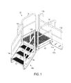
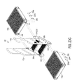
- Figure 1 of the present invention illustrates an exemplary platform system 100 comprising a platform 102, two stairways 104, and two handrails 108.
- stairways 104a and 104b are connected to one set of opposite sides of platform 102, while platform handrails 108 are connected to the other set of opposite sides of the platform.
- each side of platform 102 is configured to interchangeably connect to certain components of the platform systems described herein, such as, for example, stairways 104 and handrails 108, as illustrated in Figure 1 .
- platforms similar to platform 102 may be connected to any side of platform 102 as described in more detail below with respect to Figures 23D and 23E .
- platform handrails 108 are identical to one another. The construction of handrails 108 and the manner by which they are attached to platform 102 are described in more detail below with respect to Figures 6 , 7A , 7B , and 26 .
- stairways 104a and 104b are also identical to one another.
- Each stairway 104 comprises a pair of stairway supports 114 attached to platform 102 at one end and resting on a surface, such as the ground, on the other.
- the ensuing explanation refers to the components illustrated in Figures 13, 14 , and 15 , as well as components similar thereto and described herein, as “stairway supports.” Those skilled in the art should appreciate, however, that these components may be known as or referred to as “stringers” or “stairway stringers” in the relevant art.
- Stairway supports 114 may be attached to a surface, the ground, or another component in the manner described below with respect to Figures 13, 14 , 15 , 23A , 23B , 23C , 29A , and 29B .
- stairway supports 114a and 114b are mirror images of one another but are otherwise similar in construction and use. The construction of stairway supports 114 and the manner by which they are attached to platform 102 are described in more detail below.
- Each stairway 104 also comprises two stairway handrails 110 that are connected to stairway supports 114. That is, stairway handrail 110a is connected to stairway support 114a, while stairway handrail 110b is connected to stairway support 114b.
- stairway handrails 110a and 110b are mirror images of one another but are otherwise similar in construction, manufacture, and use, as describe in more detail below.
- Stairways 104 also include one or more steps 112 interposed between stairway supports 114a and 114b. In this embodiment, steps 112 allow a user to access platform 102. The construction of steps 112 and the manner by which they are attached to stairway supports 114 are described in more detail below.
- FIG. 2 illustrates another exemplary platform system 200 comprising a platform area 202 connected to a stairway 204.
- Platform area 202 comprises a plurality of platforms 102 connected to one another. As described above, each side of platforms 102 is configured to interchangeably connect to any of the other platforms, as well as other components of the platform systems described herein, as explained in more detail below.
- Platform area 202 also includes a plurality of handrails 108 attached to various sides of platforms 102, as illustrated. Also as explained above, any of handrails 108 may be interchangeably attached to any side of platforms 102 to which another component is not already attached.
- platform system 200 also comprises two stands 210 connected to the underside of two different platforms 102 in order to provide support to platform area 202. That is, stand 210a is connected to platform 102a, while stand 210b is connected to platform 102b.
- stand 210a is connected to platform 102a
- stand 210b is connected to platform 102b.
- stands connected to and that support the platforms may vary in height in order to account for the location and desired height of the corresponding platforms. It should be understood, however, that each of platforms 102 are configured to interchangeably connect to a stand, if desired, irrespective of the stand's height.
- the construction of stands 210 and the manner by which they are connected to platforms 102 are described in more detail below with respect to Figures 17 through 22B , 27A, and 27B .
- Stairway 204 comprises a pair of stairway supports 216 connected to platform 102c at one end and may be connected to a surface at the other.
- Stairway supports 216a and 216b are mirror images of one another but are otherwise identical in construction and use.
- Stairway supports 216 are interconnected by a number of steps 112, in a manner similar to that described above with respect to stairway supports 114 and steps 112 of Figure 1 .
- a stairway handrail 218a is connected to stairway support 216a, while another stairway handrail 218b is connected to stairway support 216b.
- Stairway handrails 218a and 218b are mirror images of one another but are otherwise identical in construction and use.
- stairway supports 216 and stairway handrails 218 are similar to stairway supports 114 and stairway handrails 110, respectively, of Figure 1 . In this example, however, both stairway supports 216 and stairway handrails 218 exhibit a length greater than respective stairway supports 114 and handrails 110 of Figure 1 in order to accommodate for the additional steps of platform system 200 and thus its additional height.
- FIG. 3 illustrates yet another exemplary platform system 300 comprising platform area 202, a stairway 302, another platform area 304, and stairway 104.
- Stairway 302 is connected to platform area 202 on one side and to platform area 304 on the other.
- the side of platform area 304 opposite the side connected to stairway 302 is connected to stairway 104.
- Stairway 302 comprises two stairway supports 306, two stairway handrails 308, and two steps 112.
- Stairway supports 306a and 306b are mirror images of one another but are otherwise identical in construction and use.
- Stairway handrails 308a and 308b are also mirror images of one another but are otherwise identical in construction and use.
- Stairway handrail 308a is connected to stairway support 306a, while stairway handrail 308b is connected to stairway handrail 306b.
- stairway supports 306 and handrails 308 are similar in construction and use to stairway supports 114 and handrails 110, albeit smaller due to the relatively lesser height of stairway 302 (and the removal of one of steps 112) in comparison to stairway 104.
- steps 112 are interconnected between stairway supports 306, to which stairway handrails 324 and 326 are also connected, respectively. The formation and attachment of the components of the stairways are described in more detail below.
- Platform area 304 comprises platform 102a and two handrails 108, in a manner similar to that described above with respect to Figure 1 . That is, handrails 108 are connected to opposite sides of platform 102a, and stairway 104 is connected to another side of the platform. One side of platform 102a is connected to stairway 302 opposite the side connected to stairway 104. In the presently-described embodiment, a user accesses platform area 202 by walking in a straight line stairway 104, across platform area 304, and up stairway 302.
- each side of platform 102 is configured to interchangeably connect to the components of the platform systems described herein.
- any stairway or handrail, another platform, or other components described below may be connected to any of the sides of platform 102.
- a stand may be connected to the underneath of any of the platform's sides. The connection between the components of the platform systems may be accomplished in the manners explained below or in manners similar thereto.
- the configurations of the platform systems' components described herein allow the components to be arranged and rearranged in order to design and build a platform system in any desired configuration.
- the direction of stairway 104 may be changed to be perpendicular to the direction of stairway 302 by switching the sides of platform 102a to which stairway 104 and handrail 108a are connected. That is, handrail 108a and stairway 104 may be disconnected from platform 102a, switched, and reconnected to the platform.
- a user would then access platform area 202 by walking up stairway 104, turning right approximately ninety (90) degrees ("°"), crossing platform area 304, and continuing up stairway 302 to platform area 202.
- the embodiments of the present invention allow one to design and/or install a platform system for a specific location and use without designing and manufacturing the platform system or its components specifically for that location.
- a manufacturer may mass-produce the components as described herein without designing, altering, or manufacturing components specific to the installation; that is, without the necessity to modify the underlying components based upon each installation.
- Those skilled in the art should appreciate that this allows the manufacturer to maintain a supply of interchangeable parts, which reduces engineering, design, manufacture, and installation costs.
- such a platform system and the components thereof allow a system to be customized for each installation regardless of the size or shape of the system needed without any customized manufacturing.
- FIG 4 is a perspective view of platform 102 comprising a top surface 400 surrounded by four identical sides 402.
- Platform 102 is formed from a single, continuous piece of sheet metal as described below with respect to Figure 5 .
- the single, continuous piece of sheet metal is approximately three-sixteenths inch (3/16") plate or sheet metal, although it should be understood that other suitable materials may be used.
- the single, continuous piece of sheet metal is lasered or otherwise cut so that each side 402 of platform 102 defines a plurality of apertures 404.
- Apertures 404 are configured to allow components of a platform system to interchangeably connect to platform 102 as referred to above and described in more detail below.
- Platform 102 is approximately three feet wide by three feet deep (3' x 3') and exhibits a height of approximately six inches (6"). It should be understood, however, that while platform 102 is approximately square in the illustrated embodiment, the platform may be designed to exhibit other shapes, dimensions, and sizes, such as a rectangle, without departing from the scope of the present invention.
- FIG 5 is a top planar view of a single, continuous piece 500 of sheet metal used to form platform 102 ( Figures 1 through 4 ).
- single, continuous piece 500 of sheet metal is lasered or otherwise cut to take the form as shown in Figure 5 and to define apertures 404 described above, as well as additional apertures 502 and 508.
- the uses of apertures 404, 502, and 508 are described in more detail below. It should be understood that a tube laser, a cutting drill, a screw machine, a handheld plasma or flame torch, or other suitable instrument may be used to laser, butterfly, or otherwise cut continuous piece 500 of sheet metal as described herein.
- each side 402 of the continuous piece of metal is folded down with respect to surface 400 along a fold line 504 at approximately a 90° angle.
- Each side 402 is then folded again inward along a fold line 506 at approximately another 90° angle, thereby forming platform 102.
- the corners/connections between each adjacent side 402 may be welded if desired.
- FIG. 6 is a perspective view of platform handrail 108 comprising an outer rail 602 and a midrail 604, each of which is formed from a single, continuous piece of tubular metal. It should be understood that both outer rail 602 and midrail 604 may be manufactured from the same single, continuous piece of tubular metal. That is, the single, continuous piece of tubular metal may be separated into the two continuous pieces of tubular metal that are used to form outer rail 602 and midrail 604, respectively.
- Handrail 108 further comprises a toeboard 606 formed from a single, continuous piece of sheet metal.
- Figures 7A and 7B are top and side elevation views, respectively, of the single, continuous piece of tubular metal used to form outer rail 602.
- the continuous piece of tubular metal is cut to define a plurality of apertures 608 and then folded at approximately forty-five degrees (45°) at each of fold lines 700 in order to form outer rail 602.
- a threaded insert configured to receive a threaded bolt or other suitable fastener is inserted into each of apertures 608 as illustrated in Figure 7B .
- Bolts or suitable fasteners are then passed through apertures defined by other components of the system and inserted into the threaded inserts in order to connect the component to handrail 108 as explained below.
- outer rail 602 is connected to platform 102 in this manner as described in more detail with respect to Figure 26 .
- suitable threaded inserts are those sold by AVK Instrustrial Products of Valencia, California.
- outer rail 602 is cut to define apertures on the inner side of the rail at points 702 and 704. As the continuous piece of tubular metal is folded, the ends of midrail 604 and toeboard 606 are inserted into points 702 and 704, respectively, in a manner similar to that described in the patent applications incorporated by reference above and specifically application no. 12/537,842 .
- the connections between outer rail 602 and midrail 604 and the outer rail and toeboard 606 may be welded if desired.
- FIG 8 is a perspective view of a handrail washer 800 formed from a single, continuous piece 802 of tubular metal.
- handrail washer 800 may be formed from ultra-high molecular weight (“UHMW”) polyethylene, polyvinyl chloride (“PVC”), or other suitable type of plastic, as should be understood by those skilled in the art.
- UHMW ultra-high molecular weight
- PVC polyvinyl chloride
- Single, continuous piece 802 of tubular metal is cut to define apertures 804 and to otherwise take the form as illustrated in Figure 8 . That is, one side of handrail washer 800 exhibits a flat surface, while the opposite side of the washer exhibits a curved, concave surface, as illustrated.
- Handrail washer 800 may be used to connect a component of the platform system that exhibits a curved surface to one that does not. For instance, handrail washer 800 is placed between a flat side 402 of platform 102 ( Figure 4 ) and a curved leg of platform handrail 108 ( Figure 6 ) when the two are connected. The use of handrail washer 800 is described below in further detail with respect to Figures 23A and 26 .
- Figure 9 is a perspective view of stairway handrail 308a comprising a first handrail portion 902, a second handrail portion 904 connected to handrail portion 902, and a third handrail portion 906 connected between handrail portions 902 and 904.
- Each of handrail portions 902, 904, and 906 is formed from a single, continuous piece of tubular metal.
- handrail 308a is a mirror image of handrail 308b ( Figure 3 ), which is therefore not described in more detail herein.
- Second handrail portion 904 is cut to define an aperture at point 908 configured to receive an end of first handrail portion 902 and then folded at approximately 45° at a fold line 910. Second handrail portion 904 is folded at an angle slightly less than 45° at a fold line 912 so that the resulting handrail 900 may be used as a stairway handrail. That is, the angles at which portion 904 is folded cause handrail 308a to exhibit a downward slope in a fashion typically shown by stairway handrails. During formation, second handrail portion 904 is also cut to define an aperture at point 914 configured to receive an end of third handrail portion 906.
- First handrail portion 902 is cut to define apertures at points 915 and 916 in order to receive the respective ends of second handrail portion 904 and third handrail portion 906.
- First handrail portion 902 is then folded at approximately 45° at fold lines 918 and at approximately 90° at another fold line 920. It should be understood that the angles at which portions of handrail 308a are folded are not, in and of themselves, critical to the formation of the handrail, and other angles may be utilized as desired.
- first handrail portion 902 is being folded, respective ends of second handrail portion 904 and third handrail portion 906 are inserted into apertures at points 915 and 916, respectively.
- the connections made by inserting an end of a handrail portion into an aperture defined by another handrail portion may be welded if desired.
- each of handrail portions 902 and 904 are cut to define a pair of apertures 922.
- threaded inserts are included within each aperture 922 in order to connect handrail 308a to a stairway support, such as support 306a ( Figure 1 ), as described in more detail below with respect to Figure 23A .
- stairway handrail 308a is dependent upon the length of the stairway (and, thus, the number of steps) with which the handrail will be used. It should be appreciated that stairway handrail 308a may be extended and the components thereof enlarged in order to accommodate a stairway of greater length.
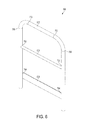
- Figure 10 illustrates stairway handrail 110a that comprises a first handrail portion 1002, a second handrail portion 1004, and a third handrail portion 1006.
- Stairway handrail 110a is a mirror image of stairway handrail 110b ( Figures 1 and 3 ), which is therefore not described in further detail herein.
- first handrail portion 1002 is similar in construction and size to handrail portion 9002, while handrails portions 1004 and 1006 have been extended in length in comparison to their respective counterparts 904 and 906. Portions 1002 and 1004 are cut to define apertures 1008 that are similar to apertures 922. That is, threaded inserts may be included within apertures 1008 in order to connect handrail 110a to a stairway support, similar to the manner described in more detail below with respect to Figure 23A . Stairway handrail 110a is otherwise formed in a manner similar to that by which stairway handrail 308a is formed.
- stairway handrail 110a and the components thereof may be further extended to account for stairways of even greater length in comparison to those described above.
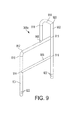
- Figure 11 illustrates a stairway handrail 1100a exhibiting a length greater than that of stairway handrail 308a ( Figure 9 ) and 110a ( Figure 10 ).
- stairway handrail 1100a comprises a first handrail portion 1102 and a second handrail portion 1104.
- first handrail portion 1102 is similar to first handrail portions 902 and 1002.
- Second handrail portion 1104 has been extended to account for an associated stairway of additional length (i.e., that includes additional steps) in comparison to portions 904 and 1004. Due to the additional length of second handrail portion 1104, an additional vertical handrail portion 1106 is inserted into, and supports, the second handrail portion at an aperture 1108 defined by second handrail portion 1104.
- third handrail portions 906 and 1006 have been segmented into two horizontal handrail portions 1110 and 1112. Each side of vertical handrail portion 1106 defines an aperture configured to receive an end of handrail portions 1110 and 1112, respectively.
- portions 1110 and 1112 are a single, continuous piece of metal that is inserted into and passed through the apertures defined by the sides of portion 1106 during formation of handrail 1100.
- portions 1102, 1104, and 1106 are cut to define apertures 1114 similar to apertures 922 and apertures 1008.
- Stairway handrail 1100a is otherwise formed in a manner similar to that described above with respect to stairway handrails 110a and 308a.
- handrail portions 1106, 1110, and 1112 are also each formed from single, continuous pieces of tubular metal.
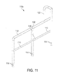
- stairway handrail 218a exhibits a length greater than stairway handrail 1100a ( Figure 11 ).
- Handrail 218a is a mirror image of handrail 218b ( Figure 2 ), which is therefore not described in further detail.
- stairway handrail 218a comprises stairway handrail portions 1202, 1204, 1206, 1208, and 1210 similar to respective portions 1102, 1104, 1112, 1110, and 1106 of handrail 1100a.
- Each of handrail portions 1202, 1204, and 1210 are cut to define apertures 1212 that are similar to apertures 1114.
- threaded inserts may be included in apertures 1114 and 1212 in order to connect handrails 1100a and 218a, respectively, to corresponding stairway supports, as described in more detail below with respect to Figure 24A .
- Handrail 218a is otherwise constructed and formed in a manner similar to that described above with respect to handrail 1100a.
- handrails 110a, 218a, 308a, and 1100a of Figures 10 , 12 , 9 , and 11 are designed to be located on one side of a stairway, while a mirror image of each handrail is designed to be used on the opposite side of the stairway.
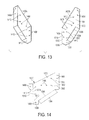
- FIG 13 illustrates a pair of stairway supports 1400a and 1400b configured to attach to a platform and to interconnect a step in a manner similar to that described above with regard to stairway supports 114, 216, and 306 of Figures 1 , 2 , and 3 , respectively.
- Each of stairway supports 1400 is formed from a single, continuous piece of sheet metal, although it should be understood that the same single, continuous piece of sheet metal may be used to form both supports.
- a single, continuous piece 1300 of sheet metal may be used to form stairway support 1400b.
- stairway support 1400b is a mirror image of stairway support 1400a.
- stairway support 1400a is formed in a similar manner.
- Single, continuous piece 1300 of metal is first cut in order to take the form illustrated in Figure 14 in order to form stairway support 1400b.
- areas 1302, 1304, 1308, and 1312 are folded inward at approximately 90° with respect to an area 1301 at respective fold lines 1304, 1306, 1310, and 1314.
- Single, continuous piece 1300 of sheet metal is cut to define a plurality of apertures 1404, 1406, 1408, 1410, and 1412.
- Apertures 1404 are configured to receive hardware used to connect stairway supports 1400a and 1400b to a platform, such as platform 102 ( Figures 1 through 4 ), at one end, in a manner similar to that as described in more detail below with respect to Figures 23C and 24C .
- apertures 1406 are configured to receive hardware to connect the stairway supports to another platform at the opposite end, in a manner similar to that described in more detail below with respect to Figure 23C .
- Apertures 1408 are configured to receive hardware to connect the stairway support to a step.
- apertures 1408 and the approximate hardware allow a step to be interconnected between stairway supports 1400, as described in more detail below with respect to Figures 23A , 23B , 24A , and 25A .
- Apertures 1412 are configured to receive hardware to connect the stairway support to a stairway handrail, as described in more detail below with respect to Figure 23A .
- Apertures 1410 are used to affix the supports to the ground or to a fixed structure if the ends of stairway supports 1400 defining apertures 1410 are located at ground level or on top of the fixed structure.
- a pair of bolts or anchors may be affixed to the ground or another structure so that an end of each bolt or anchor distal from the portion of the bold or anchor affixed to the ground or other structure is directed upward, away from, and perpendicular to the ground or fixed structure.
- the distal end of each bolt or anchor passes through a respective aperture 1410, which may be secured to the bolt or anchor via a nut and washer combination or other suitable fastener.
- Apertures 1410 may also be used to connect stairway supports 1400 to another component, such as a mobile kit, as described in more detail below with respect to Figures 29A and 29B .
- Each of stairway supports 1400 includes a single pair of apertures 1408 configured to interconnect a single step. It should therefore be understood that stairway supports 1400 are configured to form a stairway comprising a single step and thus are relatively shorter in length than stairway supports 114, 216, and 306 described above with regard to Figures 1 , 2 , and 3 , respectively. Similar to the explanations set forth above with respect to Figures 9 , 10 , 11 , and 12 regarding the ability to extend the length of the stairway handrails to accommodate greater stairway lengths, however, the length of the stairway supports may be extended for the same reasons in a similar fashion.
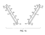
- FIG 15 illustrates stairway supports 216 exhibiting lengths greater than that of stairway supports 1400 of Figure 13 .
- Each of stairway supports 216 defines five pairs of apertures 1508 in order to interconnect five steps, as illustrated in Figure 2 .
- the present invention contemplates stairway supports of varying sizes in order to build stairways comprising a different number of steps.
- stairway supports 216 are formed in a manner similar to that described above with respect to the formation of stairway supports 1400. That is, single, continuous pieces of sheet metal are cut and folded to form each stairway support 216. Each continuous piece of sheet metal is cut to define apertures 1504, 1506, 1508, 1510, and 1512, which are similar in construction, function, and use to apertures 1404, 1406, 1408, 1410, and 1412, respectively.
- apertures 1510 may be used to connect stairway supports 216 to the ground, another structure, or a mobile kit, similar to the operation of apertures 1410, as explained above.
- each of stairway supports 216 defines an extra pair of apertures 1512 in comparison to apertures 1412 defined by stairway supports 1400. It should be understood that the additional length of stairway supports 216 in comparison to supports 1400 necessitates the additional pair of apertures 1512 to enable supports 216 to connect to stairway handrails exhibiting extended lengths (and, thus, having an extra handrail portion), such as handrails 1100a and 218a described above with regard to Figures 11 and 12 , respectively.
- each stairway support 216 may define a third aperture 1504 below the two apertures 1504 illustrated in Figure 15 in order to connect stairway supports exhibiting such a greater length to another component, such as platform 102 ( Figures 1 through 4 ), as described in more detail below with respect to Figures 24A and 24C .
- stairway supports may be manufactured in a manner similar to that by which stairway supports 1400 and 216 are formed as described above. This is to accommodate for the desired height and length of any stairway of a platform system, such as stairways 104 and 302 ( Figures 1 and 3 , respectively) defined by stairway supports 114 and 306. That is, shorter or longer stairway supports may be formed to accommodate for a greater or lesser number of steps in a manner consistent with the above description without departing from the scope of the present invention.
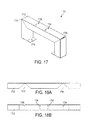
- Figure 16A is a perspective view of such a step 112 in accordance with an embodiment of the present invention.
- Figure 16B is a top planar view of a single, continuous piece 1600 of sheet metal from which step 112 is formed. Referring to Figures 16A and 16B , single, continuous piece 1600 of sheet metal is cut to take the form illustrated in Figure 16B and to define apertures 1604. A plurality of sides 1608 are folded down at approximately 90° with respect to an area 1602 at respective fold lines 1610.
- step 112 The manner by which apertures 1604 are used to connect step 112 between two stairway supports is described in more detail below with respect to Figures 23A , 23B , 24A , and 25A . It should be understood from the ensuing explanation that any number of steps 112 may be used to form a stairway depending on the desired height and length of the stairway.
- Figure 17 is a perspective view of a stand 1700 formed from a single, continuous piece 1702 of tubular metal.
- Figures 18A and 18B are front and top elevation views, respectively, of continuous piece 1702 of tubular metal. Referring to Figures 17, 18A, and 18B , continuous piece 1702 of tubular metal is cut to define apertures 1704 and 1710 and to define areas 1708.
- Stand 1700 is formed in a manner similar to that described in the applications referenced above and specifically application no. 12/537,842. That is, continuous piece 1702 of tubular metal is then folded at areas 1708 in order to form stand 1700 as illustrated. Once folded, areas 1908 may be welded together if desired.
- Stand 1700 may be used to support platform 102 ( Figures 1 through 4 ) in a manner similar to that described above with respect to stands 210 of Figures 2 and 3 . In one embodiment, this is accomplished by introducing threaded inserts into apertures 1704. A threaded bolt or other suitable fastener passes through the platform and into one of the threaded inserts located within the corresponding aperture 1704, as described in more detail below with respect to Figures 27A and 27B . Examples of suitable threaded inserts are those offered for sale by AVK Industrial Products mentioned above.
- Suitable hardware such as an anchor or a bolt, may be used to affix stand 1700 to the ground via apertures 1710 defined in the bottom surface of the stand in a manner similar to that described above with respect to stairway supports 1400 of Figures 13 and 14 .
- stand 1700 may be extended to accommodate for other heights at which the associated platform may be located.
- a stand 1900 is illustrated exhibiting a height greater than that of stand 1700.
- stand 1900 is formed from a single, continuous piece 1902 of tubular metal, which is cut to define apertures 1904 and 1910, as well as areas 1908.
- Stand 1900 is then formed in a manner similar to that described above with regard to stand 1700. That is, continuous piece 1902 of tubular metal is folded at approximately 90° at areas 1908. Similar to that described above with respect to apertures 1704 of Figure 17 , threshold inserts are placed in apertures 1904.
- Stand 1900 is otherwise constructed and may be utilized in a manner similar to the construction and use of stand 1700, as described in more detail below with respect to Figures 27A and 27B .
- stand 1900 may not be of a height sufficient for all platform systems. Accordingly, the height of the stand may be increased to support platforms located at an even greater height, such as stand 210 described above with respect to Figures 2 and 3 . However, depending on the stand's height it may require additional supports.
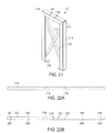
- Figure 21 illustrates stand 210 exhibiting a height greater than that of stands 1700 and 1900.
- stand 2100 comprises an outer rail 2102 and a pair of cross supports 2110 and 2112, each of which is formed from a single, continuous piece of metal, in this embodiment. The continuous piece of metal forming outer rail 2102 is cut to define apertures 2104 and 2114, slots 2200, and areas 2108.
- the tubular pieces of metal used to form cross supports 2110 and 2112 are cut so that each end of the cross supports define a pair of tabs in a manner similar to that described in application no. 12/537,842 referenced above.
- Slots 2200 are relatively small, slit-shaped apertures configured to receive these tabs on the ends of cross supports 2110 and 2112 when outer rail 2102 is folded at areas 2108. That is, as outer rail 2102 is folded, the pair of tabs defined by each end of cross supports 2110 and 2112 is inserted into a respective pair of slots 2200. The intersections of the tabs and slots may be welded if desired.
- Outer rail 2102 is otherwise formed in a manner similar to that described above with regard to stands 1700 ( Figure 17 ) and 1900 ( Figure 19 ), as well as that described in the applications incorporated by reference above.
- Cross support 2112 is also cut to define an aperture in the middle of the support configured to receive cross support 2110, as illustrated in Figure 21 .
- the attachment of a platform to stand 210 is described in more detail below with respect to Figures 27A and 27B . Those skilled in the art should thus appreciate that stands of other heights may be constructed and used in a similar manner.
- FIGS 23A and 23B illustrate a process for forming stairway 302 in accordance with an embodiment of the present invention.
- stairway 302 comprises two handrails 110, two stairway supports 306, and two steps 112. While the ensuing explanation is directed to the specific components illustrated in Figures 23A and 23B , it should be understood that it is also applicable to components and, thus, stairways, of sizes and dimensions different than those illustrated. That is, the formation of stairways for platform systems as described herein is accomplished in a manner similar to that described with respect to Figures 23A and 23B regardless of the number of steps and the relatively lesser or greater dimensions of the stairway as compared to stairway 302. Those skilled in the art should thus appreciate that stairway handrails are connected to stairway supports of comparable lengths and interconnected with an analogous number of steps in a manner similar to that described below.
- handrail washers 800 are placed between stairway supports 306 and each portion 1002 and 1004 of handrails 110 in order to connect the handrails to the stairway supports in one embodiment.
- each of apertures 1412 is coaxially aligned with a respective aperture 804 and 1008.
- the cylindrical portion of a bolt and washer combination 2300 is passed through each set of aligned apertures 804, 1008, and 1412 and rotated into the threaded inserts included within apertures 1008.
- Bolt and washer combinations 2300 are tightened into the threaded inserts in order to connect each handrail 110 to the respective stairway support 306.
- Apertures 1410 may be used to secure stairway 302 to a surface, such as the ground, in a manner described above with respect to Figures 13 and 14 .
- each of apertures 1408 of stairway support 306b is coaxially aligned with a corresponding aperture 1604 on the right side of steps 112 in order to connect the steps to stairway support 306b.
- each of apertures 1408 of stairway support 306a is coaxially aligned with a corresponding aperture 1604 on the left side of steps 112.
- the cylindrical portion of each threaded bolt and washer combination 2300 is inserted through a corresponding pair of aligned apertures 1408 and 1604.
- a nut is tightened on the end of each bolt and washer combination 2300 that passes through apertures 1408 and 1604 in order to fasten steps 112 to stairway supports 306.
- a threaded insert similar to those described above is inserted into each aperture 1604 of steps 112. In such an embodiment, each bolt and washer combination is introduced to the respective threaded insert and rotated in order to connect the steps to the stairway supports.
- FIGS 23B and 23C illustrate a process for connecting stairway 302 to one or more platforms in accordance with an embodiment of the present invention.
- a side of the platform is placed adjacent stairway supports 306 so that each aperture 1404 of the supports coaxially aligns with a respective aperture 404 of the platform.
- a backing plate 2302 defining a pair of apertures is placed adjacent the surface of the side of the platform in contact with stairway supports 306 opposite the surface in contact with the supports so that each aperture of the backing plate coaxially aligns with a respective pair of aligned apertures 404 and 1404.
- the cylindrical end of threaded bolt and washer combination 2300 is passed through each set of the aligned apertures as illustrated.
- Platform 102a along with backing plate 2032, is secured to stairway supports 306 by attaching a washer and nut combination 2304 to the cylindrical end of each bolt and washer combination and tightened. That is, a washer 2304b is placed over the cylindrical end of the bolt passed through the aligned apertures and adjacent to backing plate 2302, and a nut 2304a is rotated about the bolt's end. As a result, platform 102a is connected to stairway supports 306. While only one set of backing plate 2302 and washer and nut combination 2304 is illustrated in Figure 23C as connecting platform 102a to stairway support 306b, it should be understood that another backing plate and another washer and nut combination are used to connect platform 102a to stairway support 306a. It should also be understood that, while Figure 23C illustrates connecting stairway 302 comprising two steps 112 to platforms 102, the description is similarly applicable to the process of connecting stairways exhibiting both lesser and greater numbers of steps to the platforms.
- a second platform 102b may be connected to the side of stairway 302 opposite the side connected to platform 102a. This may be accomplished in a manner similar to that described above with respect to platform 102a. That is, each aperture 1406 of stairway supports 306 is coaxially aligned with a corresponding aperture 404 of platform 102b and a corresponding aperture defined by backing plates 2302. The cylindrical end of threaded bolt and washer combination 2300 is passed through each set of aligned apertures 1406, 404, and those defined by the backing plate. Platform 102b, along with backing plate 2032, is secured to stairway supports 306 via a washer and nut combination 2304 in the manner described above.
- backing plate 2302 and one washer and nut combination 2304 are illustrated in Figure 23C connecting platform 102b to stairway support 306b, it should be understood that another backing plate and another washer and nut combination are used to connect platform 102b to stairway support 306a.
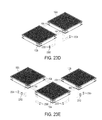
- FIGS 23D and 23E illustrate exemplary processes for connecting one or more platforms together.
- a side of platform 102a is placed adjacent a side of platform 102b so that each apertures 404 defined by the side of one platform align with a respective aperture 404 defined by the side of the other platform.
- Platforms 102a and 102b are connected in a manner similar to that described above with respect to platform 102a and supports 306 of Figure 23C . That is backing plates 2302 are placed adjacent an inside surface of the side of one platform in contact with the side of the other platform. In this example, backing plate 2302 is placed adjacent the inner surface of the side of platform 102b in contact with the side of platform 102a.
- each aperture of backing plates 2302 is coaxially aligned with a respective coaxially aligned pair of apertures 404 of the two platforms.
- the cylindrical end of bolt and washer combination 2300 is passed through each coaxially aligned set of apertures. Washer and nut combinations 2304 are then used to secure platforms 102a and 102b together by attaching to the cylindrical end of each bolt.
- platform 102a may be connected to platform 102b on one side and platform 102c on another.
- Platform 102a is connected to platforms 102b and 102c in the manner described above with respect to Figure 23D . That is, platforms 102b and 102c are placed adjacent to different sides of platform 102a so that apertures 404 defined by the adjacent sides of the platforms are coaxially aligned.
- Backing plates 2302, bolt and washer combinations 2300 and washer and nut combinations 2304 are used to secure the platforms together, as illustrated, in a manner similar to that described above. It should be understood from the foregoing explanation that any number, configuration, and arrangement of platforms 102 may be created by the process of connecting the platforms together described above.
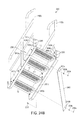
- Figures 24A and 24B illustrate an exemplary process for building another stairway 2400 of a platform system exhibiting a length greater than that of stairway 302 described above.
- stairway 2400 comprises two handrails 1100, two stairway supports 2401, and four steps 112.
- Steps 112 are connected to stairway supports 2401 in a manner similar to that described above with respect to Figures 23A and 23B . That is, threaded bolt and washer combinations 2300 are passed through coaxially aligned apertures 1408 and 1604 in order to connect steps 112 to stairway supports 2401.
- the threaded bolt and washer combinations are secured in place via washer and nut combinations 2304 in one embodiment and via threaded inserts within apertures 1604 in another.
- Handrails 1100 are likewise connected to stairways supporting 2401 in a manner similar to that described above with reference to Figures 23A and 23B . That is, handrail washers 800 are placed between stairway supports 2401 and portions 1102, 1104, and 1106 of handrails 1100. Threaded bolt and washer combinations 2300 are passed through coaxially aligned apertures 1408 of stairway supports 2401, 804 ( Figure 8 ) of handrail washers 800, and 1114 ( Figure 11 ) of stairway handrails 1100. The threaded bolt and washer combinations are then rotated into threaded inserts included within apertures 1114 in order to secure the stairway washers, handrails, and supports together.
- additional support may be provided by one or more cross supports connecting the stairway supports underneath the steps.
- a cross support 2408 is cut from a single, continuous piece of sheet metal into the shape illustrated in Figures 24A and 24B .
- the piece of sheet metal is also cut to define a pair of apertures 2410 on opposite ends of cross support 2408 as shown.
- Stairway supports 2401 are also cut to define apertures 2412 that correspond to apertures 2410 when cross beam 2408 is placed across the underside of stairway 2400 as illustrated particularly with respect to Figure 24B . That is, aperture 2410a coaxially aligns with aperture 2412a, while aperture 2410b coaxially aligns with aperture 2412b.
- Threaded bolt and washer combinations 2300 are inserted through aligned apertures 2410 and 2412 and secured in place via respective washer and nut combinations 2304. It should be understood that additional cross supports may be necessary to support stairways exhibiting lengths greater than that of stairway 2400, examples of which are described in more detail below with respect to Figures 25A and 25B .
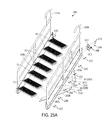
- Figures 24A , 24B , and 24C illustrate a process for connecting stairway 2400 to platform 102 in accordance with another embodiment of the present invention.
- a pair of gussets 2402 is used in combination with a pair of backing plates 2302 in order to connect the stairway to the platform.
- a horizontal surface of gussets 2402 defines a pair of apertures 2406, and a vertical surface defines a slot 2414.
- Platform 102 is first connected to stairway supports 2401 in a manner similar to that described above with respect to platform 102a and supports 306 of Figure 23C . That is, threaded bolt and washer combinations 2300 are passed through apertures 1404a and 1404b, corresponding apertures 404 ( Figure 4 ), and the respective apertures defined by backing plate 2302. Washer and nut combinations 2304 are tightened on the bolt in order to secure the platform to the stairway supports.
- Gussets 2402 are then placed underneath platform 102 so that each aperture 2406 defined by the gussets coaxially aligns with a respective aperture 508 of the platform.
- the cylindrical end of threaded bolt and washer combination 2300 is passed through each pair of aligned apertures 2406 and 508 and secured in place via washer and nut combination 2304.
- the portions of stairway supports 2401 in contact with platform 102 are cut to define a third aperture 1404c below apertures 1404a and 1404b in a manner similar to that described above with respect to Figure 15 .
- Gussets 2402 are located so that each aperture 1404c aligns with a respective slot 2414 of each gusset.
- the cylindrical end of threaded bolt and washer combination 2300 is inserted through each aligned pair of additional aperture 1404c and slot 2414 and secured in place by washer and nut combination 2304. As a result, platform 102 is secured to stairway 2400 in this manner.
- FIGS. 25A and 25B illustrate stairways 2500, 2502, and 2504 comprising differing numbers of steps 112 and exhibiting varying heights.
- stairway 2500 comprises stairway supports 2506 and handrails 2508 of different lengths than the stairway supports and handrails described above.
- stairway 2502 includes stairway handrails 2510 and supports 2514
- stairway 2504 includes stairway handrails 2512 and supports 2516 that differ in size and length as compared to the stairway handrails and supports described above.
- Stairways 2500 and 2502 include a second cross support 2408b in addition to cross support 2408a to provide additional stability to the stairways. Due to its relatively greater length, stairway 2504 includes a third cross support 2408c in addition to cross supports 2408a and 2408b. Stairways 2500, 2502, and 2504 are constructed and configured to connect to other components of a platform system in manners similar to that described above with respect to Figures 23A through 24C .
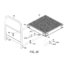
- FIG 26 illustrates an exemplary process for connecting handrail 108 to platform 102.
- handrail washers 800 are placed between platform 102 and handrail 108 so that the washers' concave surfaces are in contact with the handrail's legs and the flat surfaces are in contact with side 402a of platform 102.
- each aperture 804 ( Figure 8 ) defined by washers 800 are coaxially aligned with a respective aperture 608 and a respective aperture 404.
- Washers 2300b are placed adjacent each aperture 404 of the inner surface of side 402a opposite the outer surface that is in contact with handrail washers 800.
- Each washer 2300b is placed so that the aperture defined by the washer also coaxially aligns with each aligned set of apertures 404, 804 ( Figure 8 ), and 608. Threaded bolts 2300a are inserted into each aligned set of apertures and rotated into the threaded insert located within aperture 608 thereby securing platform 102 to handrail 108.
- FIG. 27A illustrates an exemplary process for connecting platform 102 to stand 1900.
- platform 102 is positioned on top of stand 1900 so that a pair of apertures 502 of the platform coaxially aligns with a pair of apertures 1904a of the stand.
- Two washers 2300b are placed over apertures 502 so that each washer aligns with a respective aligned pair of an aperture 502 and an aperture 1904a.
- Threaded bolts 2300a are then passed through each aligned set of washer 2300b, aperture 502, and aperture 1904a. Threaded bolts 2300a are then tightened into the respective threaded inserts located within apertures 1904a.
- platform 102 may be connected to stands of other heights in a manner similar to that described above.
- FIG 27B illustrates an exemplary process for connecting multiple platforms 102 to stand 210.
- platform 102a is positioned on top of stand 210 so that a pair of apertures 502a of the platform coaxially aligns with a pair of apertures 2104a of the stand.
- Platform 102b is positioned on top of stand 210 in a similar fashion so that a pair of apertures 502b of the platform coaxially aligns with a pair of apertures 2104b of the stand.
- Washers 2300b are placed over apertures 502 so that each washer aligns with a respective pair of an aperture 502 and an aperture 1904. Threaded bolts 2300a are then passed through each aligned washer 2300b, aperture 504, and aperture 2104. The threaded bolts are then tightened into the threaded inserts located within apertures 2104.
- the stands described herein may be used to support the connection between two adjacent platforms. Although not illustrated, it should be understood that the adjacent platforms may be connected to one another in the manner described above with respect to Figures 23D and 23E . It should also be understood that the two platforms may be connected to a stand of a different height than that of stand 210 in a manner similar to that described above.
- FIG. 28A , 28Bm and 28C illustrate a ladder component
- Figures 29A and 29B illustrate a pair of mobile units that may be used with the platform systems described herein as explained in further detail below.
- ladder component 2800 comprises two support beams 2802, a plurality of rungs 2804, and two handrails 2806.
- Each of handrails 2806 is connected to a top surface of a respective support beam 2802 at one end of the handrail and to a top surface of a respective bracket 2402 at the other end of the handrail.
- Each support beam 2802 defines a plurality of apertures to receive an end of each rung 2804.
- Support beams 2802 are identical to one another.
- Each of handrails 2806 and support beams 2802 is formed from a single, continuous piece of tubular metal in a manner similar to the formation of the handrails and stands described both above and in the applications incorporated herein by reference.
- Ladder component 2800 is otherwise constructed and attached to platform 102 in a manner similar to that described above.
- backing plates 2302 and gussets 2402 are used to connect support beams 2802 to platform 102 in a manner similar to that described above with respect to Figure 24C . That is, bolt and washer combinations 2300 are passed through each coaxially aligned set of apertures 404 and those defined by backing plate 2302 and set of apertures 508 ( Figure 5 ) and 2406 and secured into place by washer and nut combinations 2304.
- the base of support beams 2802 define an aperture 2114 that may be used to secure ladder component 2800 to a surface, such as the ground, in a manner similar to that described above with respect to Figures 13, 14 , 15 , 17 , 19 , and 21 .
- mobile units 2900 allow mobilization of a platform system or a selected portion thereof.
- the platform system comprises stairway 2400, platform 102, handrails 108, and stand 210.
- Stairway 2400 is connected to platform 102 in the manner described above with respect to Figure 24C .
- Handrails 108 are connected to platform 102 in the manner described above with respect to Figure 26 .
- Stand 210 is connected to platform 102 in a manner similar to that described above with respect to Figure 27A .
- mobile units 2900 are configured to connect to various components of the platform systems described herein, such as stairway supports 2401 and stand 210 as shown. Mobile units 2900 may be connected to one another via chains 2902 if desired.
- Each mobile unit 2900 comprises a base 2904 and a pair of wheeled portions 2906, each of which includes a wheel 2908 connected to a wheel bracket 2910.
- Each bracket 2910 includes an elongated portion 2912 configured to slideably pass through an aperture 2914 defined by base 2904 and into a tray portion 2916 of the base.
- Each elongated portion 2912 defines a plurality of apertures 2918 that correspond to apertures 2920 defined by the corresponding tray portion 2916.
- Each, elongated portion 2912 may be guided in and out of the respective tray portion 2916 in order to extend the corresponding wheeled portion 2906 away from or closer to base 2904.
- a suitable fastener is then passed through one or more corresponding coaxially aligned pairs of apertures 2918 and 2920 and tightened in order to secure each wheeled portion 2906 in a desired position.
- Base 2904 also defines apertures 2922 and 2924 that are configured to allow other components of the platform system to connect to mobile unit 2900.
- stairway 2400 is connected to mobile unit 2900a by coaxially aligning apertures 1410 of stairway supports 2401 with apertures 2922 of base 2904.
- a suitable fastener such as the threaded bolt, nut, and washer combinations referenced above, is then used to secure stairway supports 2401 to base 2904 in a manner similar to that described above.
- stand 210 is connected to mobile unit 2900b by coaxially aligning apertures 2114 of the stand with apertures 2924 of base 2904.
- a suitable fastener is then used to secure stand 210 to base 2904 in a manner similar to that described above.
- each side of the platform is configured to receive a number of interchangeable components of a platform system.
- each side of the platform is identical and defines a universal hole/mounting pattern.
- the other components of the platform system configured to attach to the platform, including other platforms may be interchangeably connected to any side of the platform.
- This allows the platform system to be constructed and arranged as desired or necessary to fit a particular installation or environment.
- This also allows the components of the platform system to be mass-produced without knowledge of the particular installation.
- the platform system may then be designed "on the fly" without the necessity to alter the components for the installation.
- the ability to mass-produce the components without the need to alter the components reduces the costs associated with both the components themselves and the overall installation.
Landscapes
- Engineering & Computer Science (AREA)
- Architecture (AREA)
- Mechanical Engineering (AREA)
- Civil Engineering (AREA)
- Structural Engineering (AREA)
- Steps, Ramps, And Handrails (AREA)
- Ladders (AREA)
- Refuge Islands, Traffic Blockers, Or Guard Fence (AREA)
- Escalators And Moving Walkways (AREA)
- Handcart (AREA)
- Bridges Or Land Bridges (AREA)
Abstract
Description
- The present invention relates to fall restraint equipment, and, more particularly, to a modular platform system.
- Platform systems typically provide access from one location of an area to another and generally fall within one of two categories: crossover platforms and access platforms. Crossover platforms usually provide a path from one location to another while going up and over an area or obstruction and back down to the other area. For instance, crossover platforms may be built to provide a path over pipes, tripping hazards, conveyors, spill containment berms, etc. In contrast, access platforms typically allow a user to reach or access a desired area or object from another location. For example, access platforms may be built to provide access to the mezzanine or office area in a factory, warehouse, or other facility or to provide access to a valve, maintenance hatch, or other object.
- A platform system is typically designed for a specific location. The components of the platform system are then manufactured so the platform system can be installed in that location. The location must first be analyzed in order to design the components of the particular platform system to fit the location. The components are then manufactured, and the platform system is installed, which is typically accomplished by the designer and/or manufacturer of the platform system. This is because the designer/manufacturer possesses the knowledge to install the components and/or alter or replace the components should they not fit the location with a satisfactory degree of precision. The necessity that each platform system be designed for a specific location can substantially increase the cost of the platform system. The major portions of such platform systems are presently constructed by a process involving cutting and welding a large number of smaller components together. The process requires a relatively substantial amount of time, manpower, and components.
- The present invention recognizes and addresses the foregoing considerations, and others, of prior art construction and methods.
- In this regard, one aspect of the present invention provides a platform that includes a plurality of identical sides. The platform is created from a single, continuous piece of sheet metal that is cut and folded to form the platform. Each side of the platform defines a set of apertures that allow the respective side of the platform to interchangeably connect to one of a plurality of components that are likewise configured to connect to the platform.
- Another aspect of the present invention provides a platform system comprising a platform and at least two other components. The platform has a plurality of identical sides, each of which defines a first set of apertures. Each of the other two components defines a second set of apertures. The first set of apertures aligns with the second set of apertures in order to allow the platform to interchangeably connect with either of the two other components. In one embodiment, the other components comprise a handrail and a pair of stairway supports. In other embodiments, the platform system comprises additional components, such as ladders and stands, configured to connect to the platform. The additional components define apertures that align with apertures defined by the platform in order to connect the component to the platform. The apertures also allow the platform to connect to other platforms.
- The accompanying drawings, which are incorporated in and constitute a part of this specification, illustrate one or more embodiments of the present invention.
- A full and enabling disclosure of the present invention, including the best mode thereof directed to one of ordinary skill in the art, is set forth in the specification, which makes reference to the appended drawings, in which:
-
Figures 1 ,2 , and3 are perspective views of exemplary platform systems in accordance with various embodiments of the present invention; -
Figure 4 is a perspective view of a platform for a platform system in accordance with an embodiment of the present invention; -
Figure 5 is a top planar view of a continuous piece of sheet metal cut to form the platform ofFigure 4 ; -
Figure 6 is a perspective view of a platform handrail for a platform system in accordance with an embodiment of the present invention; -
Figures 7A and 7B are top and side planar views, respectively, of a continuous piece of tubular metal cut to form the platform handrail ofFigure 6 ; -
Figure 8 is a perspective view of a handrail washer that may be used in combination with various handrails in a platform system in accordance with embodiments of the present invention; -
Figures 9 ,10 ,11 , and12 are perspective views of exemplary stairway handrails for a platform system in accordance with various embodiments of the present invention; -
Figure 13 is a perspective view of an exemplary pair of stairway supports for a platform system in accordance with an embodiment of the present invention; -
Figure 14 is a top planar view of a continuous piece of sheet metal cut to form one of the stairway supports ofFigure 13 ; -
Figure 15 is a perspective view of another exemplary pair of stairway supports for a platform system in accordance with an embodiment of the present invention; -
Figure 16A is a perspective view of a step for a platform system in accordance with an embodiment of the present invention; -
Figure 16B is a top planar view of a continuous piece of sheet metal cut to form the step ofFigure 16A ; -
Figure 17 is a perspective view of a stand for a platform system in accordance with an embodiment of the present invention; -
Figures 18A and 18B are side and top planar views, respectively, of a continuous piece of tubular metal cut to form the stand ofFigure 17 ; -
Figure 19 is a perspective view of a stand for a platform system in accordance with an embodiment of the present invention; -
Figures 20A and 20B are side and top planar views, respectively, of a continuous piece of tubular metal cut to form the stand ofFigure 19 ; -
Figure 21 is a perspective view of a stand that may be used in a platform system in accordance with an embodiment of the present invention; -
Figures 22A and 22B are side and top planar views, respectively, of a continuous piece of tubular metal cut to form the stand ofFigure 21 ; -
Figures 23A and23B illustrate an exemplary process for forming a stairway of a platform system in accordance with an embodiment of the present invention; -
Figure 23C illustrates an exemplary process for connecting the stairway ofFigure 23A to other components of a platform system in accordance with an embodiment of the present invention; -
Figures 23D and 23E illustrate exemplary processes for connecting multiple platforms of a platform system together in accordance with various embodiments of the present invention; -
Figures 24A and24B illustrate an exemplary process for forming a stairway of a platform system in accordance with an embodiment of the present invention; -
Figure 24C illustrates an exemplary process for connecting the stairway ofFigures 24A and24B to other components of a platform system in accordance with an embodiment of the present invention; -
Figure 25A illustrates an exemplary process for forming a stairway of a platform system in accordance with an embodiment of the present invention; -
Figure 25B is a bottom view of exemplary stairways for a platform system in accordance with various embodiments of the present invention; -
Figure 26 illustrates an exemplary process for connecting the platform handrail ofFigure 6 to the platform ofFigure 4 in accordance with an embodiment of the present invention; -
Figure 27A illustrates an exemplary process for connecting the platform ofFigure 4 to the stand ofFigure 19 in accordance with an embodiment of the present invention; -
Figure 27B illustrates an exemplary process for connecting multiple platforms to the stand ofFigure 21 in accordance with an embodiment of the present invention; -
Figure 28A is a perspective view of a ladder component for a platform system in accordance with an embodiment of the present invention; -
Figures 28B and28C are perspective views of the ladder component ofFigure 28A connected to other components of a platform system in accordance with embodiments of the present invention; -
Figure 29A is a perspective view of an exemplary platform system that includes a pair of mobile units in accordance with an embodiment of the present invention; andFigure 29B is a perspective view of one of the mobile kits ofFigure29A . - Repeat use of reference characters in the present specification and drawings is intended to represent same or analogous features or elements of the invention.
- Reference will now be made in detail to presently preferred embodiments of the invention, one or more examples of which are illustrated in the accompanying drawings. Each example is provided by way of explanation of the invention, not limitation of the invention. In fact, it will be apparent to those skilled in the art that modifications and variations can be made in the present invention without departing from the scope or spirit thereof. For instance, features illustrated or described as part of one embodiment may be used on another embodiment to yield a still further embodiment. Thus, it is intended that the present invention covers such modifications and variations as come within the scope of the appended claims and their equivalents.
- Aspects of the present invention are related to fall restraint equipment. Examples of fall restraint equipment and the components thereof are set forth in copending
U.S. patent applications 12/329,883 12/468,704 12/487,408 12/537,842 12/552,811 12/837,480 61/366,612 61/374,541 -
Figure 1 of the present invention illustrates anexemplary platform system 100 comprising aplatform 102, twostairways 104, and twohandrails 108. In the presently-described embodiment,stairways platform 102, whileplatform handrails 108 are connected to the other set of opposite sides of the platform. - As explained in more detail below, each side of
platform 102 is configured to interchangeably connect to certain components of the platform systems described herein, such as, for example,stairways 104 andhandrails 108, as illustrated inFigure 1 . Moreover, other platforms similar toplatform 102 may be connected to any side ofplatform 102 as described in more detail below with respect toFigures 23D and 23E . In the presently-described embodiment,platform handrails 108 are identical to one another. The construction ofhandrails 108 and the manner by which they are attached toplatform 102 are described in more detail below with respect toFigures 6 ,7A ,7B , and26 . - In this embodiment,
stairways stairway 104 comprises a pair of stairway supports 114 attached toplatform 102 at one end and resting on a surface, such as the ground, on the other. The ensuing explanation refers to the components illustrated inFigures 13, 14 , and15 , as well as components similar thereto and described herein, as "stairway supports." Those skilled in the art should appreciate, however, that these components may be known as or referred to as "stringers" or "stairway stringers" in the relevant art. Stairway supports 114 may be attached to a surface, the ground, or another component in the manner described below with respect toFigures 13, 14 ,15 ,23A ,23B ,23C ,29A , and29B . In the present embodiment, stairway supports 114a and 114b are mirror images of one another but are otherwise similar in construction and use. The construction of stairway supports 114 and the manner by which they are attached toplatform 102 are described in more detail below. - Each
stairway 104 also comprises two stairway handrails 110 that are connected to stairway supports 114. That is,stairway handrail 110a is connected tostairway support 114a, whilestairway handrail 110b is connected tostairway support 114b. In this embodiment,stairway handrails Stairways 104 also include one ormore steps 112 interposed between stairway supports 114a and 114b. In this embodiment, steps 112 allow a user to accessplatform 102. The construction ofsteps 112 and the manner by which they are attached to stairway supports 114 are described in more detail below. -
Figure 2 illustrates anotherexemplary platform system 200 comprising aplatform area 202 connected to astairway 204.Platform area 202 comprises a plurality ofplatforms 102 connected to one another. As described above, each side ofplatforms 102 is configured to interchangeably connect to any of the other platforms, as well as other components of the platform systems described herein, as explained in more detail below.Platform area 202 also includes a plurality ofhandrails 108 attached to various sides ofplatforms 102, as illustrated. Also as explained above, any ofhandrails 108 may be interchangeably attached to any side ofplatforms 102 to which another component is not already attached. - In the presently-described embodiment,
platform system 200, and specificallyplatform area 202, also comprises twostands 210 connected to the underside of twodifferent platforms 102 in order to provide support toplatform area 202. That is,stand 210a is connected toplatform 102a, whilestand 210b is connected toplatform 102b. The ensuing explanation refers to the components labeled as 210 inFigure 2 and those illustrated inFigures 17 through 22B , as well as the components similar thereto and described herein, as "stands." Those skilled in the art should appreciate, however, that these components may be known as or referred to as "supports" or "platform supports" in the relevant art. As explained in more detail below, stands connected to and that support the platforms may vary in height in order to account for the location and desired height of the corresponding platforms. It should be understood, however, that each ofplatforms 102 are configured to interchangeably connect to a stand, if desired, irrespective of the stand's height. The construction ofstands 210 and the manner by which they are connected toplatforms 102 are described in more detail below with respect toFigures 17 through 22B ,27A, and 27B . -
Stairway 204 comprises a pair of stairway supports 216 connected toplatform 102c at one end and may be connected to a surface at the other. Stairway supports 216a and 216b are mirror images of one another but are otherwise identical in construction and use. Stairway supports 216 are interconnected by a number ofsteps 112, in a manner similar to that described above with respect to stairway supports 114 andsteps 112 ofFigure 1 . Additionally, astairway handrail 218a is connected tostairway support 216a, while anotherstairway handrail 218b is connected tostairway support 216b.Stairway handrails - Those skilled in the art should appreciate that stairway supports 216 and stairway handrails 218 are similar to stairway supports 114 and stairway handrails 110, respectively, of
Figure 1 . In this example, however, both stairway supports 216 and stairway handrails 218 exhibit a length greater than respective stairway supports 114 and handrails 110 ofFigure 1 in order to accommodate for the additional steps ofplatform system 200 and thus its additional height. -
Figure 3 illustrates yet anotherexemplary platform system 300 comprisingplatform area 202, astairway 302, anotherplatform area 304, andstairway 104.Stairway 302 is connected toplatform area 202 on one side and toplatform area 304 on the other. The side ofplatform area 304 opposite the side connected tostairway 302 is connected tostairway 104. -
Stairway 302 comprises two stairway supports 306, two stairway handrails 308, and twosteps 112. Stairway supports 306a and 306b are mirror images of one another but are otherwise identical in construction and use.Stairway handrails Stairway handrail 308a is connected tostairway support 306a, whilestairway handrail 308b is connected tostairway handrail 306b. Those skilled in the art should appreciate that stairway supports 306 and handrails 308 are similar in construction and use to stairway supports 114 and handrails 110, albeit smaller due to the relatively lesser height of stairway 302 (and the removal of one of steps 112) in comparison tostairway 104. In a manner similar to that described above with respect tostairway 104,steps 112 are interconnected between stairway supports 306, to which stairway handrails 324 and 326 are also connected, respectively. The formation and attachment of the components of the stairways are described in more detail below. -
Platform area 304 comprisesplatform 102a and twohandrails 108, in a manner similar to that described above with respect toFigure 1 . That is,handrails 108 are connected to opposite sides ofplatform 102a, andstairway 104 is connected to another side of the platform. One side ofplatform 102a is connected tostairway 302 opposite the side connected tostairway 104. In the presently-described embodiment, a user accessesplatform area 202 by walking in astraight line stairway 104, acrossplatform area 304, and upstairway 302. - As explained above, each side of
platform 102 is configured to interchangeably connect to the components of the platform systems described herein. For instance, any stairway or handrail, another platform, or other components described below may be connected to any of the sides ofplatform 102. Moreover, a stand may be connected to the underneath of any of the platform's sides. The connection between the components of the platform systems may be accomplished in the manners explained below or in manners similar thereto. - Those skilled in the art should understand from the description that follows that the configurations of the platform systems' components described herein allow the components to be arranged and rearranged in order to design and build a platform system in any desired configuration. For instance, the direction of
stairway 104 may be changed to be perpendicular to the direction ofstairway 302 by switching the sides ofplatform 102a to whichstairway 104 andhandrail 108a are connected. That is,handrail 108a andstairway 104 may be disconnected fromplatform 102a, switched, and reconnected to the platform. A user would then accessplatform area 202 by walking upstairway 104, turning right approximately ninety (90) degrees ("°"), crossingplatform area 304, and continuing upstairway 302 toplatform area 202. Those skilled in the art should appreciate that such manipulations in the layout of a platform system similar toplatform systems Figures 1 ,2 , and3 allow the platform system to be configured to meet the unique requirements of the environment in which the platform system is to be installed. That is, the platform system may be modified due to the interchangeability of its components to fit the location in which it will be installed without the necessity to modify the components themselves. - As shown by the examples above, the embodiments of the present invention allow one to design and/or install a platform system for a specific location and use without designing and manufacturing the platform system or its components specifically for that location. As a result, a manufacturer may mass-produce the components as described herein without designing, altering, or manufacturing components specific to the installation; that is, without the necessity to modify the underlying components based upon each installation. Those skilled in the art should appreciate that this allows the manufacturer to maintain a supply of interchangeable parts, which reduces engineering, design, manufacture, and installation costs. It should also be understood that such a platform system and the components thereof allow a system to be customized for each installation regardless of the size or shape of the system needed without any customized manufacturing.
-
Figure 4 is a perspective view ofplatform 102 comprising atop surface 400 surrounded by fouridentical sides 402.Platform 102 is formed from a single, continuous piece of sheet metal as described below with respect toFigure 5 . In the presently-described embodiment, the single, continuous piece of sheet metal is approximately three-sixteenths inch (3/16") plate or sheet metal, although it should be understood that other suitable materials may be used. During formation, the single, continuous piece of sheet metal is lasered or otherwise cut so that eachside 402 ofplatform 102 defines a plurality ofapertures 404.Apertures 404 are configured to allow components of a platform system to interchangeably connect toplatform 102 as referred to above and described in more detail below.Platform 102 is approximately three feet wide by three feet deep (3' x 3') and exhibits a height of approximately six inches (6"). It should be understood, however, that whileplatform 102 is approximately square in the illustrated embodiment, the platform may be designed to exhibit other shapes, dimensions, and sizes, such as a rectangle, without departing from the scope of the present invention. -
Figure 5 is a top planar view of a single,continuous piece 500 of sheet metal used to form platform 102 (Figures 1 through 4 ). Referring toFigures 4 and5 , single,continuous piece 500 of sheet metal is lasered or otherwise cut to take the form as shown inFigure 5 and to defineapertures 404 described above, as well asadditional apertures apertures continuous piece 500 of sheet metal as described herein. - In order to form
continuous piece 500 of metal intoplatform 102, eachside 402 of the continuous piece of metal is folded down with respect tosurface 400 along afold line 504 at approximately a 90° angle. Eachside 402 is then folded again inward along afold line 506 at approximately another 90° angle, thereby formingplatform 102. After being folded, the corners/connections between eachadjacent side 402 may be welded if desired. -
Figure 6 is a perspective view ofplatform handrail 108 comprising anouter rail 602 and amidrail 604, each of which is formed from a single, continuous piece of tubular metal. It should be understood that bothouter rail 602 andmidrail 604 may be manufactured from the same single, continuous piece of tubular metal. That is, the single, continuous piece of tubular metal may be separated into the two continuous pieces of tubular metal that are used to formouter rail 602 andmidrail 604, respectively.Handrail 108 further comprises atoeboard 606 formed from a single, continuous piece of sheet metal. -
Figures 7A and 7B are top and side elevation views, respectively, of the single, continuous piece of tubular metal used to formouter rail 602. Referring toFigures 6 ,7A, and 7B , the continuous piece of tubular metal is cut to define a plurality ofapertures 608 and then folded at approximately forty-five degrees (45°) at each offold lines 700 in order to formouter rail 602. A threaded insert configured to receive a threaded bolt or other suitable fastener is inserted into each ofapertures 608 as illustrated inFigure 7B . Bolts or suitable fasteners are then passed through apertures defined by other components of the system and inserted into the threaded inserts in order to connect the component to handrail 108 as explained below. For instance,outer rail 602 is connected toplatform 102 in this manner as described in more detail with respect toFigure 26 . Examples of suitable threaded inserts are those sold by AVK Instrustrial Products of Valencia, California. - Additionally,
outer rail 602 is cut to define apertures on the inner side of the rail atpoints midrail 604 andtoeboard 606 are inserted intopoints 12/537,842 outer rail 602 and midrail 604 and the outer rail andtoeboard 606 may be welded if desired. -
Figure 8 is a perspective view of ahandrail washer 800 formed from a single,continuous piece 802 of tubular metal. As with all the other components described herein, it should be understood that other suitable materials may be used to form the components. For instance,handrail washer 800 may be formed from ultra-high molecular weight ("UHMW") polyethylene, polyvinyl chloride ("PVC"), or other suitable type of plastic, as should be understood by those skilled in the art. Single,continuous piece 802 of tubular metal is cut to defineapertures 804 and to otherwise take the form as illustrated inFigure 8 . That is, one side ofhandrail washer 800 exhibits a flat surface, while the opposite side of the washer exhibits a curved, concave surface, as illustrated.Handrail washer 800 may be used to connect a component of the platform system that exhibits a curved surface to one that does not. For instance,handrail washer 800 is placed between aflat side 402 of platform 102 (Figure 4 ) and a curved leg of platform handrail 108 (Figure 6 ) when the two are connected. The use ofhandrail washer 800 is described below in further detail with respect toFigures 23A and26 . -
Figure 9 is a perspective view ofstairway handrail 308a comprising afirst handrail portion 902, asecond handrail portion 904 connected tohandrail portion 902, and athird handrail portion 906 connected betweenhandrail portions handrail portions handrail 308a is a mirror image ofhandrail 308b (Figure 3 ), which is therefore not described in more detail herein. -
Second handrail portion 904 is cut to define an aperture atpoint 908 configured to receive an end offirst handrail portion 902 and then folded at approximately 45° at afold line 910.Second handrail portion 904 is folded at an angle slightly less than 45° at afold line 912 so that the resulting handrail 900 may be used as a stairway handrail. That is, the angles at whichportion 904 is foldedcause handrail 308a to exhibit a downward slope in a fashion typically shown by stairway handrails. During formation,second handrail portion 904 is also cut to define an aperture atpoint 914 configured to receive an end ofthird handrail portion 906. -
First handrail portion 902 is cut to define apertures atpoints second handrail portion 904 andthird handrail portion 906.First handrail portion 902 is then folded at approximately 45° atfold lines 918 and at approximately 90° at anotherfold line 920. It should be understood that the angles at which portions ofhandrail 308a are folded are not, in and of themselves, critical to the formation of the handrail, and other angles may be utilized as desired. Asfirst handrail portion 902 is being folded, respective ends ofsecond handrail portion 904 andthird handrail portion 906 are inserted into apertures atpoints handrail portions apertures 922. In one embodiment, threaded inserts are included within eachaperture 922 in order to connecthandrail 308a to a stairway support, such assupport 306a (Figure 1 ), as described in more detail below with respect toFigure 23A . - It should be understood that the size of
stairway handrail 308a is dependent upon the length of the stairway (and, thus, the number of steps) with which the handrail will be used. It should be appreciated thatstairway handrail 308a may be extended and the components thereof enlarged in order to accommodate a stairway of greater length.Figure 10 , for example, illustratesstairway handrail 110a that comprises afirst handrail portion 1002, asecond handrail portion 1004, and athird handrail portion 1006.Stairway handrail 110a is a mirror image ofstairway handrail 110b (Figures 1 and3 ), which is therefore not described in further detail herein. - Referring additionally to
Figure 9 ,first handrail portion 1002 is similar in construction and size to handrail portion 9002, whilehandrails portions respective counterparts Portions apertures 1008 that are similar toapertures 922. That is, threaded inserts may be included withinapertures 1008 in order to connecthandrail 110a to a stairway support, similar to the manner described in more detail below with respect toFigure 23A .Stairway handrail 110a is otherwise formed in a manner similar to that by whichstairway handrail 308a is formed. - It should be understood, however, that
stairway handrail 110a and the components thereof may be further extended to account for stairways of even greater length in comparison to those described above.Figure 11 , for instance, illustrates astairway handrail 1100a exhibiting a length greater than that of stairway handrail 308a (Figure 9 ) and 110a (Figure 10 ). In the presently-described embodiment,stairway handrail 1100a comprises afirst handrail portion 1102 and asecond handrail portion 1104. - Referring additionally to
Figures 9 and10 ,first handrail portion 1102 is similar tofirst handrail portions Second handrail portion 1104, however, has been extended to account for an associated stairway of additional length (i.e., that includes additional steps) in comparison toportions second handrail portion 1104, an additionalvertical handrail portion 1106 is inserted into, and supports, the second handrail portion at anaperture 1108 defined bysecond handrail portion 1104. In one embodiment,third handrail portions horizontal handrail portions vertical handrail portion 1106 defines an aperture configured to receive an end ofhandrail portions portions portion 1106 during formation of handrail 1100. Each ofportions apertures 1114 similar toapertures 922 andapertures 1008.Stairway handrail 1100a is otherwise formed in a manner similar to that described above with respect tostairway handrails handrail portions - It should be understood from the foregoing explanation that almost any sized stairway handrail may be manufactured in a manner similar to that described above. Referring to
Figure 12 , for instance,stairway handrail 218a exhibits a length greater than stairway handrail 1100a (Figure 11 ).Handrail 218a is a mirror image ofhandrail 218b (Figure 2 ), which is therefore not described in further detail. - Referring to
Figures 11 and12 ,stairway handrail 218a comprisesstairway handrail portions respective portions handrail portions apertures 1212 that are similar toapertures 1114. In certain embodiments, threaded inserts may be included inapertures handrails Figure 24A .Handrail 218a is otherwise constructed and formed in a manner similar to that described above with respect tohandrail 1100a. It should be understood that handrails 110a, 218a, 308a, and 1100a ofFigures 10 ,12 ,9 , and11 , respectively, are designed to be located on one side of a stairway, while a mirror image of each handrail is designed to be used on the opposite side of the stairway. -
Figure 13 illustrates a pair of stairway supports 1400a and 1400b configured to attach to a platform and to interconnect a step in a manner similar to that described above with regard to stairway supports 114, 216, and 306 ofFigures 1 ,2 , and3 , respectively. Each of stairway supports 1400 is formed from a single, continuous piece of sheet metal, although it should be understood that the same single, continuous piece of sheet metal may be used to form both supports. Referring additionally toFigure 14 , a single,continuous piece 1300 of sheet metal may be used to formstairway support 1400b. It should be understood, however, thatstairway support 1400b is a mirror image ofstairway support 1400a. Thus, while the ensuing explanation is directed tostairway support 1400b, it should be understood thatstairway support 1400a is formed in a similar manner. - Single,
continuous piece 1300 of metal is first cut in order to take the form illustrated inFigure 14 in order to formstairway support 1400b. Next,areas area 1301 atrespective fold lines continuous piece 1300 of sheet metal is cut to define a plurality ofapertures -
Apertures 1404 are configured to receive hardware used to connect stairway supports 1400a and 1400b to a platform, such as platform 102 (Figures 1 through 4 ), at one end, in a manner similar to that as described in more detail below with respect toFigures 23C and24C . Similarly,apertures 1406 are configured to receive hardware to connect the stairway supports to another platform at the opposite end, in a manner similar to that described in more detail below with respect toFigure 23C .Apertures 1408 are configured to receive hardware to connect the stairway support to a step. Thus,apertures 1408 and the approximate hardware allow a step to be interconnected between stairway supports 1400, as described in more detail below with respect toFigures 23A ,23B ,24A , and25A .Apertures 1412 are configured to receive hardware to connect the stairway support to a stairway handrail, as described in more detail below with respect toFigure 23A . -
Apertures 1410 are used to affix the supports to the ground or to a fixed structure if the ends of stairway supports 1400 definingapertures 1410 are located at ground level or on top of the fixed structure. In one embodiment, for example, a pair of bolts or anchors may be affixed to the ground or another structure so that an end of each bolt or anchor distal from the portion of the bold or anchor affixed to the ground or other structure is directed upward, away from, and perpendicular to the ground or fixed structure. The distal end of each bolt or anchor passes through arespective aperture 1410, which may be secured to the bolt or anchor via a nut and washer combination or other suitable fastener.Apertures 1410 may also be used to connect stairway supports 1400 to another component, such as a mobile kit, as described in more detail below with respect toFigures 29A and29B . - Each of stairway supports 1400 includes a single pair of
apertures 1408 configured to interconnect a single step. It should therefore be understood that stairway supports 1400 are configured to form a stairway comprising a single step and thus are relatively shorter in length than stairway supports 114, 216, and 306 described above with regard toFigures 1 ,2 , and3 , respectively. Similar to the explanations set forth above with respect toFigures 9 ,10 ,11 , and12 regarding the ability to extend the length of the stairway handrails to accommodate greater stairway lengths, however, the length of the stairway supports may be extended for the same reasons in a similar fashion. Referring toFigure 15 , for example, illustrates stairway supports 216 exhibiting lengths greater than that of stairway supports 1400 ofFigure 13 . Each of stairway supports 216 defines five pairs ofapertures 1508 in order to interconnect five steps, as illustrated inFigure 2 . Those skilled in the art should thus appreciate from the ensuing explanation that the present invention contemplates stairway supports of varying sizes in order to build stairways comprising a different number of steps. - Referring additionally to
Figures 13 and 14 , stairway supports 216 are formed in a manner similar to that described above with respect to the formation of stairway supports 1400. That is, single, continuous pieces of sheet metal are cut and folded to form each stairway support 216. Each continuous piece of sheet metal is cut to defineapertures apertures apertures 1510 may be used to connect stairway supports 216 to the ground, another structure, or a mobile kit, similar to the operation ofapertures 1410, as explained above. - In this embodiment, each of stairway supports 216 defines an extra pair of
apertures 1512 in comparison toapertures 1412 defined by stairway supports 1400. It should be understood that the additional length of stairway supports 216 in comparison to supports 1400 necessitates the additional pair ofapertures 1512 to enable supports 216 to connect to stairway handrails exhibiting extended lengths (and, thus, having an extra handrail portion), such ashandrails Figures 11 and12 , respectively. Additionally, each stairway support 216 may define athird aperture 1504 below the twoapertures 1504 illustrated inFigure 15 in order to connect stairway supports exhibiting such a greater length to another component, such as platform 102 (Figures 1 through 4 ), as described in more detail below with respect toFigures 24A and24C . - It should be understood by those of ordinary skill in the art that other stairway supports may be manufactured in a manner similar to that by which stairway supports 1400 and 216 are formed as described above. This is to accommodate for the desired height and length of any stairway of a platform system, such as
stairways 104 and 302 (Figures 1 and3 , respectively) defined by stairway supports 114 and 306. That is, shorter or longer stairway supports may be formed to accommodate for a greater or lesser number of steps in a manner consistent with the above description without departing from the scope of the present invention. - Those skilled in the art should appreciate that the above description provides the ability to manufacture, install, and use the same step and platform regardless of the length of a stairway of a platform system or the size of the platform system itself For example,
Figure 16A is a perspective view of such astep 112 in accordance with an embodiment of the present invention.Figure 16B is a top planar view of a single,continuous piece 1600 of sheet metal from which step 112 is formed. Referring toFigures 16A and 16B , single,continuous piece 1600 of sheet metal is cut to take the form illustrated inFigure 16B and to defineapertures 1604. A plurality ofsides 1608 are folded down at approximately 90° with respect to anarea 1602 atrespective fold lines 1610. The manner by whichapertures 1604 are used to connectstep 112 between two stairway supports is described in more detail below with respect toFigures 23A ,23B ,24A , and25A . It should be understood from the ensuing explanation that any number ofsteps 112 may be used to form a stairway depending on the desired height and length of the stairway. -
Figure 17 is a perspective view of astand 1700 formed from a single,continuous piece 1702 of tubular metal.Figures 18A and 18B are front and top elevation views, respectively, ofcontinuous piece 1702 of tubular metal. Referring toFigures 17, 18A, and 18B ,continuous piece 1702 of tubular metal is cut to defineapertures areas 1708.Stand 1700 is formed in a manner similar to that described in the applications referenced above and specifically application no. 12/537,842. That is,continuous piece 1702 of tubular metal is then folded atareas 1708 in order to formstand 1700 as illustrated. Once folded,areas 1908 may be welded together if desired. -
Stand 1700 may be used to support platform 102 (Figures 1 through 4 ) in a manner similar to that described above with respect tostands 210 ofFigures 2 and3 . In one embodiment, this is accomplished by introducing threaded inserts intoapertures 1704. A threaded bolt or other suitable fastener passes through the platform and into one of the threaded inserts located within the correspondingaperture 1704, as described in more detail below with respect toFigures 27A and 27B . Examples of suitable threaded inserts are those offered for sale by AVK Industrial Products mentioned above. Other suitable hardware, such as an anchor or a bolt, may be used to affixstand 1700 to the ground viaapertures 1710 defined in the bottom surface of the stand in a manner similar to that described above with respect to stairway supports 1400 ofFigures 13 and 14 . - It should be understood that
stand 1700 may be extended to accommodate for other heights at which the associated platform may be located. Referring additionally toFigures 19, 20A, and 20B , for example, astand 1900 is illustrated exhibiting a height greater than that ofstand 1700. Similarly, stand 1900 is formed from a single,continuous piece 1902 of tubular metal, which is cut to defineapertures areas 1908.Stand 1900 is then formed in a manner similar to that described above with regard to stand 1700. That is,continuous piece 1902 of tubular metal is folded at approximately 90° atareas 1908. Similar to that described above with respect toapertures 1704 ofFigure 17 , threshold inserts are placed inapertures 1904.Stand 1900 is otherwise constructed and may be utilized in a manner similar to the construction and use ofstand 1700, as described in more detail below with respect toFigures 27A and 27B . - It should be further understood that even stand 1900 may not be of a height sufficient for all platform systems. Accordingly, the height of the stand may be increased to support platforms located at an even greater height, such as
stand 210 described above with respect toFigures 2 and3 . However, depending on the stand's height it may require additional supports.Figure 21 , for example, illustrates stand 210 exhibiting a height greater than that ofstands Figures 22A and 22B , stand 2100 comprises anouter rail 2102 and a pair of cross supports 2110 and 2112, each of which is formed from a single, continuous piece of metal, in this embodiment. The continuous piece of metal formingouter rail 2102 is cut to defineapertures slots 2200, andareas 2108. - In one embodiment, the tubular pieces of metal used to form cross supports 2110 and 2112 are cut so that each end of the cross supports define a pair of tabs in a manner similar to that described in application no.
12/537,842 Slots 2200 are relatively small, slit-shaped apertures configured to receive these tabs on the ends of cross supports 2110 and 2112 whenouter rail 2102 is folded atareas 2108. That is, asouter rail 2102 is folded, the pair of tabs defined by each end of cross supports 2110 and 2112 is inserted into a respective pair ofslots 2200. The intersections of the tabs and slots may be welded if desired.Outer rail 2102 is otherwise formed in a manner similar to that described above with regard to stands 1700 (Figure 17 ) and 1900 (Figure 19 ), as well as that described in the applications incorporated by reference above.Cross support 2112 is also cut to define an aperture in the middle of the support configured to receivecross support 2110, as illustrated inFigure 21 . The attachment of a platform to stand 210 is described in more detail below with respect toFigures 27A and 27B . Those skilled in the art should thus appreciate that stands of other heights may be constructed and used in a similar manner. -
Figures 23A and23B illustrate a process for formingstairway 302 in accordance with an embodiment of the present invention. As explained above with reference toFigure 3 ,stairway 302 comprises two handrails 110, two stairway supports 306, and twosteps 112. While the ensuing explanation is directed to the specific components illustrated inFigures 23A and23B , it should be understood that it is also applicable to components and, thus, stairways, of sizes and dimensions different than those illustrated. That is, the formation of stairways for platform systems as described herein is accomplished in a manner similar to that described with respect toFigures 23A and23B regardless of the number of steps and the relatively lesser or greater dimensions of the stairway as compared tostairway 302. Those skilled in the art should thus appreciate that stairway handrails are connected to stairway supports of comparable lengths and interconnected with an analogous number of steps in a manner similar to that described below. - Referring additionally to
Figures 8 ,10 ,13, and 14 ,handrail washers 800 are placed between stairway supports 306 and eachportion apertures 1412 is coaxially aligned with arespective aperture washer combination 2300 is passed through each set of alignedapertures apertures 1008. Bolt andwasher combinations 2300 are tightened into the threaded inserts in order to connect each handrail 110 to the respective stairway support 306.Apertures 1410 may be used to securestairway 302 to a surface, such as the ground, in a manner described above with respect toFigures 13 and 14 . - Referring again to
Figures 23A and23B , each ofapertures 1408 ofstairway support 306b is coaxially aligned with acorresponding aperture 1604 on the right side ofsteps 112 in order to connect the steps tostairway support 306b. Likewise, each ofapertures 1408 ofstairway support 306a is coaxially aligned with acorresponding aperture 1604 on the left side ofsteps 112. The cylindrical portion of each threaded bolt andwasher combination 2300 is inserted through a corresponding pair of alignedapertures washer combination 2300 that passes throughapertures steps 112 to stairway supports 306. In another embodiment, a threaded insert similar to those described above is inserted into eachaperture 1604 ofsteps 112. In such an embodiment, each bolt and washer combination is introduced to the respective threaded insert and rotated in order to connect the steps to the stairway supports. -
Figures 23B and23C illustrate a process for connectingstairway 302 to one or more platforms in accordance with an embodiment of the present invention. In order to connect the elevated side ofstairway 302 toplatform 102a, a side of the platform is placed adjacent stairway supports 306 so that eachaperture 1404 of the supports coaxially aligns with arespective aperture 404 of the platform. Abacking plate 2302 defining a pair of apertures is placed adjacent the surface of the side of the platform in contact with stairway supports 306 opposite the surface in contact with the supports so that each aperture of the backing plate coaxially aligns with a respective pair of alignedapertures washer combination 2300 is passed through each set of the aligned apertures as illustrated.Platform 102a, along with backing plate 2032, is secured to stairway supports 306 by attaching a washer andnut combination 2304 to the cylindrical end of each bolt and washer combination and tightened. That is, awasher 2304b is placed over the cylindrical end of the bolt passed through the aligned apertures and adjacent tobacking plate 2302, and anut 2304a is rotated about the bolt's end. As a result,platform 102a is connected to stairway supports 306. While only one set ofbacking plate 2302 and washer andnut combination 2304 is illustrated inFigure 23C as connectingplatform 102a tostairway support 306b, it should be understood that another backing plate and another washer and nut combination are used to connectplatform 102a tostairway support 306a. It should also be understood that, whileFigure 23C illustrates connectingstairway 302 comprising twosteps 112 toplatforms 102, the description is similarly applicable to the process of connecting stairways exhibiting both lesser and greater numbers of steps to the platforms. - As illustrated in
Figure 23C , asecond platform 102b may be connected to the side ofstairway 302 opposite the side connected toplatform 102a. This may be accomplished in a manner similar to that described above with respect toplatform 102a. That is, eachaperture 1406 of stairway supports 306 is coaxially aligned with acorresponding aperture 404 ofplatform 102b and a corresponding aperture defined by backingplates 2302. The cylindrical end of threaded bolt andwasher combination 2300 is passed through each set of alignedapertures Platform 102b, along with backing plate 2032, is secured to stairway supports 306 via a washer andnut combination 2304 in the manner described above. While only onebacking plate 2302 and one washer andnut combination 2304 are illustrated inFigure 23C connecting platform 102b tostairway support 306b, it should be understood that another backing plate and another washer and nut combination are used to connectplatform 102b tostairway support 306a. -
Figures 23D and 23E illustrate exemplary processes for connecting one or more platforms together. In one embodiment, with reference toFigure 23D , a side ofplatform 102a is placed adjacent a side ofplatform 102b so that eachapertures 404 defined by the side of one platform align with arespective aperture 404 defined by the side of the other platform.Platforms platform 102a and supports 306 ofFigure 23C . That is backingplates 2302 are placed adjacent an inside surface of the side of one platform in contact with the side of the other platform. In this example,backing plate 2302 is placed adjacent the inner surface of the side ofplatform 102b in contact with the side ofplatform 102a. As a result, each aperture ofbacking plates 2302 is coaxially aligned with a respective coaxially aligned pair ofapertures 404 of the two platforms. The cylindrical end of bolt andwasher combination 2300 is passed through each coaxially aligned set of apertures. Washer andnut combinations 2304 are then used to secureplatforms - In another embodiment, with reference to
Figure 23E ,platform 102a may be connected toplatform 102b on one side andplatform 102c on another.Platform 102a is connected toplatforms Figure 23D . That is,platforms platform 102a so thatapertures 404 defined by the adjacent sides of the platforms are coaxially aligned.Backing plates 2302, bolt andwasher combinations 2300 and washer andnut combinations 2304 are used to secure the platforms together, as illustrated, in a manner similar to that described above. It should be understood from the foregoing explanation that any number, configuration, and arrangement ofplatforms 102 may be created by the process of connecting the platforms together described above. -
Figures 24A and24B illustrate an exemplary process for building anotherstairway 2400 of a platform system exhibiting a length greater than that ofstairway 302 described above. In this embodiment,stairway 2400 comprises two handrails 1100, two stairway supports 2401, and foursteps 112.Steps 112 are connected to stairway supports 2401 in a manner similar to that described above with respect toFigures 23A and23B . That is, threaded bolt andwasher combinations 2300 are passed through coaxially alignedapertures steps 112 to stairway supports 2401. The threaded bolt and washer combinations are secured in place via washer andnut combinations 2304 in one embodiment and via threaded inserts withinapertures 1604 in another. - Handrails 1100 are likewise connected to stairways supporting 2401 in a manner similar to that described above with reference to
Figures 23A and23B . That is,handrail washers 800 are placed between stairway supports 2401 andportions washer combinations 2300 are passed through coaxially alignedapertures 1408 of stairway supports 2401, 804 (Figure 8 ) ofhandrail washers 800, and 1114 (Figure 11 ) of stairway handrails 1100. The threaded bolt and washer combinations are then rotated into threaded inserts included withinapertures 1114 in order to secure the stairway washers, handrails, and supports together. - Depending on the length of the stairway, additional support may be provided by one or more cross supports connecting the stairway supports underneath the steps. In the presently described embodiment, such a
cross support 2408 is cut from a single, continuous piece of sheet metal into the shape illustrated inFigures 24A and24B . The piece of sheet metal is also cut to define a pair ofapertures 2410 on opposite ends ofcross support 2408 as shown. Stairway supports 2401 are also cut to defineapertures 2412 that correspond toapertures 2410 whencross beam 2408 is placed across the underside ofstairway 2400 as illustrated particularly with respect toFigure 24B . That is,aperture 2410a coaxially aligns withaperture 2412a, while aperture 2410b coaxially aligns withaperture 2412b. Threaded bolt andwasher combinations 2300 are inserted through alignedapertures nut combinations 2304. It should be understood that additional cross supports may be necessary to support stairways exhibiting lengths greater than that ofstairway 2400, examples of which are described in more detail below with respect toFigures 25A and25B . -
Figures 24A ,24B , and24C illustrate a process for connectingstairway 2400 toplatform 102 in accordance with another embodiment of the present invention. In this embodiment, a pair ofgussets 2402 is used in combination with a pair ofbacking plates 2302 in order to connect the stairway to the platform. In this embodiment, a horizontal surface ofgussets 2402 defines a pair ofapertures 2406, and a vertical surface defines aslot 2414. -
Platform 102 is first connected to stairway supports 2401 in a manner similar to that described above with respect toplatform 102a and supports 306 ofFigure 23C . That is, threaded bolt andwasher combinations 2300 are passed throughapertures Figure 4 ), and the respective apertures defined by backingplate 2302. Washer andnut combinations 2304 are tightened on the bolt in order to secure the platform to the stairway supports. -
Gussets 2402 are then placed underneathplatform 102 so that eachaperture 2406 defined by the gussets coaxially aligns with arespective aperture 508 of the platform. The cylindrical end of threaded bolt andwasher combination 2300 is passed through each pair of alignedapertures nut combination 2304. - In the presently-described embodiment, the portions of stairway supports 2401 in contact with
platform 102 are cut to define athird aperture 1404c belowapertures Figure 15 .Gussets 2402 are located so that eachaperture 1404c aligns with arespective slot 2414 of each gusset. The cylindrical end of threaded bolt andwasher combination 2300 is inserted through each aligned pair ofadditional aperture 1404c andslot 2414 and secured in place by washer andnut combination 2304. As a result,platform 102 is secured tostairway 2400 in this manner. - It should be understood by those skilled in the art that the above description provides several examples of how to construct and arrange platform systems of varying shapes, sizes, and heights using interchangeable components. Those skilled in the art should appreciate that yet more shapes, sizes, heights, and configurations of platform systems are contemplated by the present invention. For example,
Figures 25A and25B illustratestairways steps 112 and exhibiting varying heights. For example,stairway 2500 comprises stairway supports 2506 and handrails 2508 of different lengths than the stairway supports and handrails described above. Likewise,stairway 2502 includes stairway handrails 2510 and supports 2514, andstairway 2504 includes stairway handrails 2512 and supports 2516 that differ in size and length as compared to the stairway handrails and supports described above. - Stairways 2500 and 2502 include a
second cross support 2408b in addition to crosssupport 2408a to provide additional stability to the stairways. Due to its relatively greater length,stairway 2504 includes athird cross support 2408c in addition to cross supports 2408a and 2408b. Stairways 2500, 2502, and 2504 are constructed and configured to connect to other components of a platform system in manners similar to that described above with respect toFigures 23A through 24C . -
Figure 26 illustrates an exemplary process for connectinghandrail 108 toplatform 102. In this embodiment,handrail washers 800 are placed betweenplatform 102 andhandrail 108 so that the washers' concave surfaces are in contact with the handrail's legs and the flat surfaces are in contact withside 402a ofplatform 102. As a result, each aperture 804 (Figure 8 ) defined bywashers 800 are coaxially aligned with arespective aperture 608 and arespective aperture 404.Washers 2300b are placed adjacent eachaperture 404 of the inner surface ofside 402a opposite the outer surface that is in contact withhandrail washers 800. Eachwasher 2300b is placed so that the aperture defined by the washer also coaxially aligns with each aligned set ofapertures 404, 804 (Figure 8 ), and 608. Threadedbolts 2300a are inserted into each aligned set of apertures and rotated into the threaded insert located withinaperture 608 thereby securingplatform 102 tohandrail 108. -
Figure 27A illustrates an exemplary process for connectingplatform 102 to stand 1900. In this embodiment,platform 102 is positioned on top ofstand 1900 so that a pair ofapertures 502 of the platform coaxially aligns with a pair ofapertures 1904a of the stand. Twowashers 2300b are placed overapertures 502 so that each washer aligns with a respective aligned pair of anaperture 502 and anaperture 1904a. Threadedbolts 2300a are then passed through each aligned set ofwasher 2300b,aperture 502, andaperture 1904a. Threadedbolts 2300a are then tightened into the respective threaded inserts located within apertures 1904a. It should be understood thatplatform 102 may be connected to stands of other heights in a manner similar to that described above. -
Figure 27B illustrates an exemplary process for connectingmultiple platforms 102 to stand 210. In this embodiment,platform 102a is positioned on top ofstand 210 so that a pair ofapertures 502a of the platform coaxially aligns with a pair ofapertures 2104a of the stand.Platform 102b is positioned on top ofstand 210 in a similar fashion so that a pair ofapertures 502b of the platform coaxially aligns with a pair ofapertures 2104b of the stand.Washers 2300b are placed overapertures 502 so that each washer aligns with a respective pair of anaperture 502 and anaperture 1904. Threadedbolts 2300a are then passed through each alignedwasher 2300b,aperture 504, andaperture 2104. The threaded bolts are then tightened into the threaded inserts located withinapertures 2104. - Those skilled in the art should appreciate from the above description that the stands described herein may be used to support the connection between two adjacent platforms. Although not illustrated, it should be understood that the adjacent platforms may be connected to one another in the manner described above with respect to
Figures 23D and 23E . It should also be understood that the two platforms may be connected to a stand of a different height than that ofstand 210 in a manner similar to that described above. - Those skilled in the art should also appreciate that the above description discloses platform systems comprising a platform that allows various components to be interchangeably connected to any side of the platform. It should be understood that other, different components may be designed for use with the platform systems described herein that also may be interchangeably connected to the platform or other components of the platform systems. For instance,
Figures 28A , 28Bm and28C illustrate a ladder component andFigures 29A and29B illustrate a pair of mobile units that may be used with the platform systems described herein as explained in further detail below. - Referring to
Figures 28A ,28B , and28C ,ladder component 2800 comprises twosupport beams 2802, a plurality ofrungs 2804, and twohandrails 2806. Each ofhandrails 2806 is connected to a top surface of arespective support beam 2802 at one end of the handrail and to a top surface of arespective bracket 2402 at the other end of the handrail. Eachsupport beam 2802 defines a plurality of apertures to receive an end of eachrung 2804.Support beams 2802 are identical to one another. Each ofhandrails 2806 andsupport beams 2802 is formed from a single, continuous piece of tubular metal in a manner similar to the formation of the handrails and stands described both above and in the applications incorporated herein by reference. -
Ladder component 2800 is otherwise constructed and attached toplatform 102 in a manner similar to that described above. Referring specifically toFigures 28B and28C , for instance,backing plates 2302 andgussets 2402 are used to connectsupport beams 2802 toplatform 102 in a manner similar to that described above with respect toFigure 24C . That is, bolt andwasher combinations 2300 are passed through each coaxially aligned set ofapertures 404 and those defined by backingplate 2302 and set of apertures 508 (Figure 5 ) and 2406 and secured into place by washer andnut combinations 2304. The base ofsupport beams 2802 define anaperture 2114 that may be used to secureladder component 2800 to a surface, such as the ground, in a manner similar to that described above with respect toFigures 13, 14 ,15 ,17 ,19 , and21 . - Referring to
Figures 29A and29B ,mobile units 2900 allow mobilization of a platform system or a selected portion thereof. In the example illustrated inFigures 29A and29B , the platform system comprisesstairway 2400,platform 102,handrails 108, and stand 210.Stairway 2400 is connected toplatform 102 in the manner described above with respect toFigure 24C .Handrails 108 are connected toplatform 102 in the manner described above with respect toFigure 26 . Stand 210 is connected toplatform 102 in a manner similar to that described above with respect toFigure 27A . - In the presently-described embodiment,
mobile units 2900 are configured to connect to various components of the platform systems described herein, such as stairway supports 2401 and stand 210 as shown.Mobile units 2900 may be connected to one another viachains 2902 if desired. Eachmobile unit 2900 comprises abase 2904 and a pair ofwheeled portions 2906, each of which includes awheel 2908 connected to awheel bracket 2910. Eachbracket 2910 includes anelongated portion 2912 configured to slideably pass through anaperture 2914 defined bybase 2904 and into atray portion 2916 of the base. Eachelongated portion 2912 defines a plurality ofapertures 2918 that correspond toapertures 2920 defined by the correspondingtray portion 2916. Each,elongated portion 2912 may be guided in and out of therespective tray portion 2916 in order to extend the correspondingwheeled portion 2906 away from or closer tobase 2904. A suitable fastener is then passed through one or more corresponding coaxially aligned pairs ofapertures wheeled portion 2906 in a desired position. -
Base 2904 also definesapertures mobile unit 2900. In the presently-described embodiment, for instance,stairway 2400 is connected tomobile unit 2900a by coaxially aligningapertures 1410 of stairway supports 2401 withapertures 2922 ofbase 2904. A suitable fastener, such as the threaded bolt, nut, and washer combinations referenced above, is then used to secure stairway supports 2401 to base 2904 in a manner similar to that described above. Likewise, stand 210 is connected tomobile unit 2900b by coaxially aligningapertures 2114 of the stand withapertures 2924 ofbase 2904. A suitable fastener is then used to securestand 210 to base 2904 in a manner similar to that described above. Those skilled in the art should appreciate that this mobilizes the platform system illustrated inFigure 29A so that it may be moved from one location to another. - It should be understood that modifications may be made to the shape and size of any of the components described above without departing from the scope of the present invention. It should be noted, however, that should the dimensions of one component change, the dimensions of the other components may need to be altered to accommodate the changes. For instance, should a stairway support be extended in order to accommodate additional steps, the corresponding stairway handrail should be extended in a corresponding manner. Nonetheless, the above explanation provides a designer, manufacturer, installer, and operator with the ability to design, manufacturer, install, and use standard and interchangeable components of a modular platform system regardless of the shape, size, and environment of the location in which the platform system is to be installed. As a result, the costs associated with the design, manufacture, and installation of such a platform system are reduced.
- It should also be understood that the above explanation describes a platform, each side of which is configured to receive a number of interchangeable components of a platform system. In one embodiment, for instance, each side of the platform is identical and defines a universal hole/mounting pattern. As a result, the other components of the platform system configured to attach to the platform, including other platforms, may be interchangeably connected to any side of the platform. This allows the platform system to be constructed and arranged as desired or necessary to fit a particular installation or environment. This also allows the components of the platform system to be mass-produced without knowledge of the particular installation. The platform system may then be designed "on the fly" without the necessity to alter the components for the installation. The ability to mass-produce the components without the need to alter the components reduces the costs associated with both the components themselves and the overall installation.
- While one or more preferred embodiments of the invention have been described above, it should be understood that any and all equivalent realizations of the present invention are included within the scope and spirit thereof. The embodiments depicted are presented by way of example only and are not intended as limitations upon the present invention. Thus, it should be understood by those of ordinary skill in this art that the present invention is not limited to these embodiments since modifications can be made. Therefore, it is contemplated that any and all such embodiments are included in the present invention as may fall within the scope and spirit thereof.
Claims (12)
- A platform system comprising a platform including a plurality of sides, whereby the platform is created from a single, continuous piece of sheet metal that is cut and folded to form the platform, and wherein each side of the platform defines a set of apertures, wherein the set of apertures allow the respective side of the platform to interchangeably connect to a plurality of components that are configured to connect to the platform.
- The platform system of claim 1 wherein the plurality of components that are configured to interchangeably be connected to the platform comprises a pair of stairway supports, a handrail, and another platform, wherein the another platform is identical to the platform such that the another platform is configured to interchangeably receive any one of the plurality of components that are configured to connect to the platform.
- The platform system of claim 1 wherein the platform is rectangular.
- The platform system of claim 3 wherein the platform is square.
- The platform system of claim 1 wherein the one of the plurality of components is another platform, wherein the another platform is identical to the platform such that each side of the another platform is configured to interchangeably receive one of the plurality of components configured to connect to the platform.
- The platform system of claim 1 wherein the one of the plurality of components is a pair of stairway supports, where the stairway supports are configured to interconnect at least one step.
- The platform system of claim 6 wherein each of the pair of stairway supports is formed from a single, continuous piece of sheet metal, whereby the single, continuous piece of sheet metal is cut and folded to form the respective stairway support.
- The platform system of claim 6 wherein the step is formed from a single, continuous piece of sheet metal, whereby the single, continuous piece of sheet metal is cut and folded to form the step.
- The platform system of claim 1 wherein the one of the plurality of components is a handrail configured to connect to the platform.
- The platform system of claim 9 wherein an outer rail of the handrail is formed from a single, continuous piece of tubular metal, whereby the single, continuous piece of tubular metal is cut to define a set of apertures that correspond to the set of the apertures defined by each side of the platform, and whereby the single, continuous piece of tubular metal is bent to form the outer rail.
- The platform system of claim 1 further comprising a stand configured to support at least the platform, wherein each side of the platform defines a tab parallel to a top surface of the platform that is formed when the single, continuous piece of sheet metal is folded, wherein the tab defines a second set of apertures when the single, continuous piece of sheet metal is cut, and wherein a top surface of the stand defines a third set of apertures, whereby the third set of apertures correspond to the second set of apertures and allow the stand to be connected to the platform.
- The platform system of claim 11 wherein the top surface of the stand defines a fourth set of apertures, whereby the fourth set of apertures correspond to another second set of apertures of another platform adjacent to the first platform, whereby the stand may be connected to, and support, the platform and the another platform.
Applications Claiming Priority (1)
| Application Number | Priority Date | Filing Date | Title |
|---|---|---|---|
| US13/184,499 US20130015016A1 (en) | 2011-07-16 | 2011-07-16 | Platform system |
Publications (3)
| Publication Number | Publication Date |
|---|---|
| EP2549029A2 true EP2549029A2 (en) | 2013-01-23 |
| EP2549029A3 EP2549029A3 (en) | 2017-06-21 |
| EP2549029B1 EP2549029B1 (en) | 2023-06-07 |
Family
ID=45869496
Family Applications (1)
| Application Number | Title | Priority Date | Filing Date |
|---|---|---|---|
| EP12176489.8A Active EP2549029B1 (en) | 2011-07-16 | 2012-07-16 | Platform system |
Country Status (5)
| Country | Link |
|---|---|
| US (8) | US20130015016A1 (en) |
| EP (1) | EP2549029B1 (en) |
| DK (1) | DK2549029T3 (en) |
| ES (1) | ES2954538T3 (en) |
| FI (1) | FI2549029T3 (en) |
Families Citing this family (32)
| Publication number | Priority date | Publication date | Assignee | Title |
|---|---|---|---|---|
| US9169693B2 (en) * | 2009-09-18 | 2015-10-27 | Safe Rack Llc | Mobile access unit and cage |
| US20120006618A1 (en) * | 2010-07-07 | 2012-01-12 | Aluminium Ladder Company | Cement industry gangway and safety cage |
| US20130015016A1 (en) | 2011-07-16 | 2013-01-17 | Safe Rack Llc | Platform system |
| US9663989B2 (en) | 2012-01-23 | 2017-05-30 | Wing Enterprises, Inc. | Elevated working platform and related methods |
| US8745799B1 (en) | 2013-01-11 | 2014-06-10 | Sam Carbis Asset Management, Llc | Fall protection cage with adjustable outboard upright |
| SG11201506254SA (en) * | 2013-02-11 | 2015-09-29 | John Preston | Stair modules which co operate to form a temporary stair case |
| US9027712B2 (en) * | 2013-06-17 | 2015-05-12 | Sam Carbis Asset Management, Llc | Adaptable platform for loading and unloading railway cars |
| EP3033468B1 (en) * | 2013-08-12 | 2018-11-21 | Compagnie Générale des Etablissements Michelin | Custom mold press ladder |
| US20140353083A1 (en) * | 2014-08-14 | 2014-12-04 | Caterpillar Inc. | Walkway system for machine |
| DE102014013898A1 (en) * | 2014-09-18 | 2016-03-24 | Rosenbauer International Ag | Rescue basket, as well as equipped Hubrettungsfahrzeug |
| US9857090B2 (en) * | 2015-01-19 | 2018-01-02 | Lennox Industries, Inc. | Programmable smart thermostat |
| UY4591U (en) * | 2015-06-10 | 2016-12-30 | Grupo Bimbo Sab De Cv | MOVING STAIRCASE |
| US10087641B2 (en) * | 2015-10-07 | 2018-10-02 | Safe Rack Llc | Cage assembly for use with pivotal gangway |
| US10640983B2 (en) | 2016-03-23 | 2020-05-05 | Safe Rack Llc | Platform system |
| US10648235B2 (en) * | 2016-08-15 | 2020-05-12 | The Boeing Company | Work stand configurable for different work areas |
| US10532827B2 (en) * | 2017-05-31 | 2020-01-14 | Federal Express Corporation | Modular staircase |
| US10696232B2 (en) * | 2017-11-16 | 2020-06-30 | Cnh Industrial America Llc | Split deck rail |
| DE102018203682A1 (en) * | 2018-03-12 | 2019-09-12 | Peri Gmbh | Scaffolding stair with step supports |
| CN108756719A (en) * | 2018-05-21 | 2018-11-06 | 合肥亚美科技股份有限公司 | A kind of Operation Van of ascending a height with protection fixed function |
| CA3076649A1 (en) | 2019-03-20 | 2020-09-20 | Oliver Technologies, Inc. | Modular deck apparatus |
| US11613898B2 (en) * | 2019-04-26 | 2023-03-28 | WIFCO Steel Products, Inc. | Stairs to walkway system and method |
| US11591802B1 (en) * | 2020-02-28 | 2023-02-28 | Material Control, Inc. | Modular access system |
| CA197278S (en) * | 2020-07-30 | 2022-09-28 | Nsafe Eng Inc | Ladder port with stairs |
| CN112854706B (en) * | 2021-01-25 | 2021-09-28 | 王一雯 | Novel lift for building |
| US20220235562A1 (en) * | 2021-01-26 | 2022-07-28 | Commercial Scaffolding Companies, Inc. | Scaffolding stair system |
| USD990070S1 (en) * | 2021-08-12 | 2023-06-20 | GuangDong Peng | Pet climbing ladder |
| USD1011655S1 (en) * | 2022-05-30 | 2024-01-16 | Xiyong Han | Pet stairs |
| USD978460S1 (en) * | 2022-11-17 | 2023-02-14 | Jiyun Wang | Pet step |
| USD978461S1 (en) * | 2022-11-17 | 2023-02-14 | Jiyun Wang | Pet step |
| USD979162S1 (en) * | 2022-11-17 | 2023-02-21 | Jiyun Wang | Pet step |
| USD1005526S1 (en) * | 2023-05-26 | 2023-11-21 | Fuling Ma | Ladder |
| USD1019984S1 (en) | 2023-10-28 | 2024-03-26 | Senvok Medical Inc. | Retractable handrail |
Family Cites Families (117)
| Publication number | Priority date | Publication date | Assignee | Title |
|---|---|---|---|---|
| US3104889A (en) * | 1963-09-24 | branch | ||
| US1460680A (en) * | 1922-01-30 | 1923-07-03 | Francis T Peters | Replaceable ladder rung |
| US1593783A (en) * | 1922-03-30 | 1926-07-27 | Smith Corp A O | Rigid frame for motor vehicles |
| US1576635A (en) * | 1924-10-02 | 1926-03-16 | Wallace R Douglas | Folding table |
| US1960863A (en) * | 1930-08-06 | 1934-05-29 | Boyer J Troy | Scaffold device for use on ladders and stepladders |
| US2335046A (en) * | 1942-08-03 | 1943-11-23 | Carl C Droeger | Portable and adjustable knockdown scaffold |
| US2377211A (en) * | 1942-12-10 | 1945-05-29 | Jr William York Cocken | Floor structure |
| US2585150A (en) * | 1946-11-30 | 1952-02-12 | Daniel F Mcgill | Ladder step |
| US2594561A (en) * | 1948-06-03 | 1952-04-29 | Patent Scaffolding Co Inc | Ladder of lightweight metals |
| US2726123A (en) * | 1950-11-06 | 1955-12-06 | George A Mathews | Catwalk |
| US2694609A (en) * | 1953-09-22 | 1954-11-16 | Thomas L Trafford | Interlocking connecting table |
| US2783107A (en) * | 1955-03-11 | 1957-02-26 | Gacht Steven | Plug and socket means for connecting table tops together |
| US2899011A (en) * | 1956-10-25 | 1959-08-11 | Babits Carl | Ladder step |
| US2989141A (en) * | 1959-11-24 | 1961-06-20 | Paul N Howard | Ladder |
| US3042140A (en) * | 1960-04-15 | 1962-07-03 | Putnam Rolling Ladder Co Inc | Stepladders |
| GB945822A (en) * | 1961-04-24 | 1964-01-08 | Dee Jay Brackets Ltd | Improvements in and relating to platform supporting structures |
| US3141392A (en) * | 1962-02-16 | 1964-07-21 | Irene H Schneider | Portable sectional flooring |
| US3250401A (en) * | 1964-12-17 | 1966-05-10 | Bucyrus Erie Co | Self-erecting tower crane with bayonet joints between sections |
| US3307653A (en) * | 1966-02-07 | 1967-03-07 | Herman O Gnehm | Demountable stairway unit |
| US3349870A (en) * | 1966-08-25 | 1967-10-31 | Lieblein George | Flatstep ladder |
| US3381775A (en) * | 1967-01-03 | 1968-05-07 | Livers Bronze Company | Stair tread structure |
| US3425179A (en) * | 1967-02-15 | 1969-02-04 | Victor G Haroldson | Elevated flooring |
| GB1212983A (en) * | 1967-02-24 | 1970-11-18 | Thermo Plastics Ltd | Flooring assembly |
| US3477184A (en) * | 1967-05-08 | 1969-11-11 | Theodore W Johnson | Educational playhouse |
| US3698511A (en) * | 1970-10-06 | 1972-10-17 | Ballymore Co | Modular fixed-level work platform |
| US3693754A (en) * | 1971-03-16 | 1972-09-26 | Le Roy O Butler | Portable folding steps and landing for a mobile home and the like |
| US4060150A (en) * | 1973-09-07 | 1977-11-29 | Peter Hughes | Ladder kit |
| US4009762A (en) * | 1976-04-28 | 1977-03-01 | Lawrence Peska Associates, Inc. | Convertible ladder-carrier vehicle assembly |
| US4030255A (en) | 1976-06-28 | 1977-06-21 | Universal Bleacher Company | Folding handrail system for telescoping seating systems |
| US4143740A (en) * | 1977-12-27 | 1979-03-13 | Floyd G. Matthews | Modular stairway system for installation on structures having non-linear walls |
| US4175889A (en) * | 1978-06-12 | 1979-11-27 | JBC Enterprises, Inc. | Subfloor for offshore production platform |
| SE426468B (en) * | 1979-10-30 | 1983-01-24 | Groko Maskin Ab | LOAD PALL AND PROCEDURE FOR PREPARING A CAP |
| US4319520A (en) * | 1980-01-07 | 1982-03-16 | Westinghouse Electric Corp. | Air flow floor panel |
| US4352597A (en) * | 1981-01-12 | 1982-10-05 | Charles Kay | Slide dock |
| US4355700A (en) * | 1981-02-17 | 1982-10-26 | Matthews Wesley D | Modular stairway system for installation on structures having non-linear walls |
| US4419851A (en) * | 1981-07-23 | 1983-12-13 | Brock Manufacturing, Inc. | Stair structure for storage bins |
| US4527366A (en) * | 1981-12-21 | 1985-07-09 | Greene Welding And Hardware, Inc. | Curvilinear stairway constructions |
| DE8326410U1 (en) * | 1983-09-14 | 1983-12-29 | AluTeam Gerätebau GmbH, 5440 Mayen | GRID LIGHTING STRUCTURE |
| US4598510A (en) * | 1984-08-01 | 1986-07-08 | Wagner Iii Fred A | Modular and expandable platform system |
| DE3519519A1 (en) * | 1985-05-31 | 1986-12-04 | Dieter Steinegg-Appenzell Steeb | Structure having at least one floor, on which it is possible to walk and/or drive, and load-bearing element for the structure |
| US4630709A (en) * | 1985-11-06 | 1986-12-23 | William Taylor | Pool entry and exit device |
| GB8601770D0 (en) * | 1986-01-24 | 1986-02-26 | Lew Ways Ltd | Ladder |
| US4759162A (en) * | 1987-04-16 | 1988-07-26 | Wyse Steven J | Modular platform assembly |
| DE3832066A1 (en) * | 1987-09-23 | 1989-04-06 | Geb Layher Langer | SCAFFOLDING PART |
| US4869034A (en) | 1988-11-07 | 1989-09-26 | Hammond Robert S | Sectional circular staircase |
| US4982974A (en) * | 1989-02-03 | 1991-01-08 | Interco Tire Corporation | Adjustable high vehicle boarding step |
| JPH06100021B2 (en) | 1989-04-15 | 1994-12-12 | 好宏 与那原 | Temporary handrail device for stairs |
| US5031723A (en) * | 1989-06-20 | 1991-07-16 | Hooten Jack D | Ladder accessories |
| US5002153A (en) * | 1990-07-30 | 1991-03-26 | Haison Yuen | Ladder structure |
| FR2672917A1 (en) * | 1991-02-15 | 1992-08-21 | Fernandes Construction Inoxyda | Construction device for the production of flat surfaces and/or of grating stairs |
| JPH04277261A (en) | 1991-02-28 | 1992-10-02 | Hory Corp | Scaffold unit and successive scaffold assembling method using the scaffold unit |
| US5210988A (en) * | 1991-03-15 | 1993-05-18 | Shaifer Donald R | Gridbeam |
| USD350613S (en) * | 1992-11-02 | 1994-09-13 | Hitachi Metals America, Ltd. | Floor panel |
| US5337857A (en) * | 1993-07-27 | 1994-08-16 | Spalt Taylor E | Ladder adaptable platform |
| ES2082693B1 (en) * | 1993-09-21 | 1998-05-16 | Astral Sa | STAIRS. |
| US5408790A (en) * | 1993-12-02 | 1995-04-25 | Nch Corporation | Modular dock system |
| US5617931A (en) * | 1994-08-11 | 1997-04-08 | L. E. Zygmun And Company, Inc. | Modular scaffolding system |
| DE19503543C2 (en) | 1995-02-03 | 1999-10-14 | Wilfried Hamm | Horizontal railing system |
| US5653459A (en) * | 1995-07-24 | 1997-08-05 | Murphy; Peggy R. | Transportable modular landing assembly for a trailer |
| AUPO316696A0 (en) * | 1996-10-23 | 1996-11-14 | Longmire, Michael | A ladder attachment bracket |
| US5911288A (en) * | 1996-11-04 | 1999-06-15 | Z.A.F. Contractors, Inc. | Bridge painting platform |
| US5779208A (en) * | 1996-11-25 | 1998-07-14 | Mcgraw; Raymond V. | Movable step platform for ladders |
| USD406363S (en) * | 1997-04-02 | 1999-03-02 | W. S. Molnar Company | Anti-slip floor unit |
| TW370819U (en) * | 1998-01-23 | 1999-09-21 | Yu-Shu Chen | Structure of knock down desk |
| US20020189177A1 (en) * | 1999-05-13 | 2002-12-19 | Eve John S. | Staircase |
| US6085867A (en) * | 1999-05-28 | 2000-07-11 | Aluminum Ladder Company | Modular platform system |
| ATE356946T1 (en) * | 1999-12-21 | 2007-04-15 | Keyguard Ltd | ENERGY ABSORBER |
| CZ9904710A3 (en) * | 1999-12-23 | 2001-08-15 | Rudolf Ing. Müller | Running surface for petrol filling stations |
| EP1128020A1 (en) * | 2000-02-24 | 2001-08-29 | Genex S.r.l. | Rung ladder in composite material |
| CA2421184C (en) * | 2000-09-11 | 2008-06-17 | Jean G. Robillard | Improved self-raising platform assembly |
| US20040188176A1 (en) * | 2001-01-19 | 2004-09-30 | Wyse Steven J. | Utility scaffolding having safety features |
| FR2821886B1 (en) * | 2001-03-09 | 2004-01-30 | Sevylor Internat | LADDER, ESPECIALLY POOL LADDER |
| US6810995B2 (en) * | 2001-03-18 | 2004-11-02 | Larry Warford | Portable stairs with adjustable landing platform height |
| EP1540109A4 (en) * | 2002-06-28 | 2010-09-22 | Trevor Ross Suggate | Modular platform, walkway or ramp |
| AU2002950813A0 (en) * | 2002-08-09 | 2002-09-12 | Hexagon International Pty Ltd | Modular decking tile |
| US6763912B2 (en) * | 2002-08-29 | 2004-07-20 | Century Group, L.L.C. | Modular stair assembly |
| DE20305795U1 (en) | 2003-04-10 | 2003-06-26 | G T M Gitterroste & Treppen Gm | Method for access to container accommodation units with a modular assembly framework with platform and steps |
| US7108103B2 (en) * | 2003-05-22 | 2006-09-19 | Cosco Management, Inc. | Rigidified step ladder |
| CA2455312C (en) * | 2004-01-16 | 2012-07-03 | H-Blanchette Ltee | Weldless platform assembly |
| US7500335B1 (en) * | 2004-02-19 | 2009-03-10 | Eldean Kjose | Portable deck for recreational vehicles and fifth wheel campers |
| US20050224287A1 (en) * | 2004-03-25 | 2005-10-13 | Labrash Richard | I-beam mounted work ladder |
| AU2004202341B2 (en) * | 2004-05-27 | 2010-03-04 | Ideal Plastic Concepts (Aust.) Pty Ltd | Modular Platform Assembly & System |
| ITTV20040064U1 (en) * | 2004-12-06 | 2005-03-06 | Comparf Di Canonico Antonella | PALLET TRANSPORT GOODS AND STORAGE |
| DE202005005831U1 (en) * | 2005-04-11 | 2006-01-19 | Hymer-Leichtmetallbau Gmbh & Co. Kg | Tilt adjustable climbing aid |
| USD596317S1 (en) * | 2007-08-10 | 2009-07-14 | Steeldeck Industries Limited | Platform |
| CA2645529C (en) * | 2007-11-29 | 2013-07-02 | Wenger Corporation | Portable staging and leg bracket therefor |
| CA2708599C (en) * | 2007-12-09 | 2013-02-05 | Saferack, Llc | A gangway and method for manufacturing same |
| US8162193B2 (en) * | 2008-01-15 | 2012-04-24 | Harbor Freight Tools Usa, Inc. | Cargo carrier with vehicle attachment |
| DE102008015066A1 (en) * | 2008-03-19 | 2009-09-24 | Wilhelm Layher Verwaltungs-Gmbh | Pad unit with lift-off protection and method for securing a pad unit against lifting and method for securing a secured against lifting pad unit |
| GB0810416D0 (en) * | 2008-06-06 | 2008-07-09 | Hexago Deck Ltd | Temporary viewing platforms |
| USD608459S1 (en) * | 2008-06-10 | 2010-01-19 | Wyse Steven J | Stage deck section |
| US20100025954A1 (en) * | 2008-06-21 | 2010-02-04 | George Gottlinger | Portable service accessory for a truck tractor |
| US8261393B2 (en) | 2008-08-10 | 2012-09-11 | Saferack, Llc | Fall restraint equipment component and method for manufacturing the same |
| USD619445S1 (en) * | 2008-10-20 | 2010-07-13 | Wyse Steven J | Modular stage leg bracing |
| USD602603S1 (en) * | 2008-12-23 | 2009-10-20 | Structural Plastics, Inc. | Platform |
| US8627926B2 (en) * | 2009-05-21 | 2014-01-14 | Julian D. Gordon | Method and apparatus for a stair assembly |
| US8046858B2 (en) * | 2009-09-02 | 2011-11-01 | Safe Rack Llc | Gangway handrail and method for manufacturing the same |
| CA2693345A1 (en) * | 2010-02-17 | 2011-08-17 | G.E. Leblanc Inc. | Modular platform |
| US20110278094A1 (en) | 2010-05-17 | 2011-11-17 | Gute James W | Work platform for hydraulic fracturing operations |
| US8387191B2 (en) | 2010-07-22 | 2013-03-05 | Safe Rack Llc | Gangway bearing retainer plate |
| US8561239B2 (en) | 2010-08-17 | 2013-10-22 | Safe Rack Llc | Articulating cage |
| US8746403B1 (en) * | 2010-08-31 | 2014-06-10 | Sam Carbis Asset Management, Llc | Mobile bulk carrier/access/fall protection system |
| US8490234B2 (en) * | 2010-10-22 | 2013-07-23 | Joseph P. Rowell | Travel easy adjustable deck |
| US8904714B2 (en) * | 2011-04-06 | 2014-12-09 | Big Astor S.R.L. | Modular pedestrian tunnel |
| US20130015016A1 (en) | 2011-07-16 | 2013-01-17 | Safe Rack Llc | Platform system |
| CA2782880C (en) | 2011-07-16 | 2015-05-05 | Saferack Llc | Platform system |
| USD668359S1 (en) * | 2011-12-01 | 2012-10-02 | Tate Access Floors Leasing, Inc. | Access floor panel |
| BE1019933A3 (en) * | 2012-03-08 | 2013-02-05 | Tait Technologies Bvba | PLATFORMS SYSTEM, COMPOSITION OF VIDEO MODULES AND METHOD FOR MOUNTING THE PLATFORMS SYSTEM. |
| USD685926S1 (en) * | 2012-06-29 | 2013-07-09 | Hae Kwang Co., Ltd. | Floor panel for a clean room |
| US8813430B2 (en) * | 2012-07-09 | 2014-08-26 | The Boeing Company | Platform with adjustable support members |
| US8434273B1 (en) * | 2012-09-07 | 2013-05-07 | Greene Welding & Hardware, Inc. | Deck for roof of grain bin |
| US20140367628A1 (en) | 2013-06-17 | 2014-12-18 | Rapid EPS Ltd. | Support apparatus for barrier means and method of use thereof |
| GB2518159B (en) * | 2013-09-11 | 2021-03-31 | Beales Derek | Platform apparatus and method |
| USD737464S1 (en) * | 2013-10-13 | 2015-08-25 | William Edlington | Portable stage |
| USD754876S1 (en) * | 2014-04-08 | 2016-04-26 | Nicholas A. Ramphos | Pitched roof service platform |
| US9321489B1 (en) * | 2014-07-21 | 2016-04-26 | Aaron D. Dauner | Illuminated platform system |
| FI11281U1 (en) * | 2016-02-24 | 2016-06-13 | Erik Ahto Oy | Modular Scaffolding |
-
2011
- 2011-07-16 US US13/184,499 patent/US20130015016A1/en not_active Abandoned
- 2011-12-07 US US13/313,168 patent/US20120073902A1/en not_active Abandoned
-
2012
- 2012-07-16 ES ES12176489T patent/ES2954538T3/en active Active
- 2012-07-16 FI FIEP12176489.8T patent/FI2549029T3/en active
- 2012-07-16 DK DK12176489.8T patent/DK2549029T3/en active
- 2012-07-16 EP EP12176489.8A patent/EP2549029B1/en active Active
-
2015
- 2015-06-05 US US14/732,207 patent/US10358871B2/en active Active
-
2018
- 2018-10-30 US US29/668,357 patent/USD872310S1/en active Active
- 2018-10-30 US US29/668,360 patent/USD878635S1/en active Active
-
2019
- 2019-06-28 US US16/456,384 patent/US11447965B2/en active Active
-
2022
- 2022-03-17 US US17/697,352 patent/US11739544B2/en active Active
-
2023
- 2023-06-21 US US18/212,566 patent/US20230332420A1/en active Pending
Also Published As
| Publication number | Publication date |
|---|---|
| USD878635S1 (en) | 2020-03-17 |
| ES2954538T3 (en) | 2023-11-23 |
| US20130015016A1 (en) | 2013-01-17 |
| US20230332420A1 (en) | 2023-10-19 |
| US11447965B2 (en) | 2022-09-20 |
| US20220205322A1 (en) | 2022-06-30 |
| EP2549029A3 (en) | 2017-06-21 |
| US20120073902A1 (en) | 2012-03-29 |
| USD872310S1 (en) | 2020-01-07 |
| US20150267470A1 (en) | 2015-09-24 |
| US11739544B2 (en) | 2023-08-29 |
| DK2549029T3 (en) | 2023-09-18 |
| EP2549029B1 (en) | 2023-06-07 |
| FI2549029T3 (en) | 2023-09-07 |
| US10358871B2 (en) | 2019-07-23 |
| US20190338592A1 (en) | 2019-11-07 |
Similar Documents
| Publication | Publication Date | Title |
|---|---|---|
| EP2549029B1 (en) | Platform system | |
| US20200224427A1 (en) | Platform system | |
| KR101215330B1 (en) | Angle assembly type bridge inspection passage | |
| US11970873B2 (en) | Bearing plate of an integrated construction system | |
| US8978310B2 (en) | Staging system and method | |
| JP2011501005A (en) | Protective fence | |
| US3299590A (en) | Prefabricated, adjustable stairway, ramp or bridge | |
| KR101290296B1 (en) | Stairway structure for approaching bridge inspection passage and constructing method thereof | |
| US8640827B2 (en) | Adjustable scaffold base | |
| KR101289048B1 (en) | Built-up high load safety stair using temporary bent | |
| WO2004003312A1 (en) | Modular platform, walkway or ramp | |
| CA2782880C (en) | Platform system | |
| JP5888796B2 (en) | Gantry | |
| AU2018232939A1 (en) | Walkway | |
| EP1853774B1 (en) | A construction element | |
| JP2012526214A (en) | Scaffolding system having structural units and its assembly method | |
| AU2020244548B2 (en) | Support-weight, strengthening post, related methods of use and installations | |
| KR101973798B1 (en) | Toe Board for Scaffolding | |
| KR200480076Y1 (en) | Length adjusting horizontal pipe for a temporary structure | |
| EP3006648B1 (en) | Guard rail | |
| CN209620541U (en) | A kind of movable safety scaffold | |
| KR102638109B1 (en) | Foot plate assembly for a roof | |
| AU2010101120A4 (en) | Scaffolding system | |
| GB2457644A (en) | Trestle platform | |
| GB2551699A (en) | A platform system |
Legal Events
| Date | Code | Title | Description |
|---|---|---|---|
| PUAI | Public reference made under article 153(3) epc to a published international application that has entered the european phase |
Free format text: ORIGINAL CODE: 0009012 |
|
| 17P | Request for examination filed |
Effective date: 20120716 |
|
| AK | Designated contracting states |
Kind code of ref document: A2 Designated state(s): AL AT BE BG CH CY CZ DE DK EE ES FI FR GB GR HR HU IE IS IT LI LT LU LV MC MK MT NL NO PL PT RO RS SE SI SK SM TR |
|
| AX | Request for extension of the european patent |
Extension state: BA ME |
|
| PUAL | Search report despatched |
Free format text: ORIGINAL CODE: 0009013 |
|
| AK | Designated contracting states |
Kind code of ref document: A3 Designated state(s): AL AT BE BG CH CY CZ DE DK EE ES FI FR GB GR HR HU IE IS IT LI LT LU LV MC MK MT NL NO PL PT RO RS SE SI SK SM TR |
|
| AX | Request for extension of the european patent |
Extension state: BA ME |
|
| RIC1 | Information provided on ipc code assigned before grant |
Ipc: E04F 11/17 20060101ALI20170517BHEP Ipc: E06C 7/08 20060101ALI20170517BHEP Ipc: E04G 1/06 20060101ALI20170517BHEP Ipc: E04G 1/14 20060101ALI20170517BHEP Ipc: E06C 7/18 20060101ALI20170517BHEP Ipc: E06C 1/397 20060101ALI20170517BHEP Ipc: E06C 1/39 20060101ALI20170517BHEP Ipc: E04F 11/02 20060101ALI20170517BHEP Ipc: E04G 5/14 20060101ALI20170517BHEP Ipc: E04G 1/15 20060101ALI20170517BHEP Ipc: E04F 11/112 20060101AFI20170517BHEP Ipc: E04F 11/025 20060101ALI20170517BHEP Ipc: E04F 11/18 20060101ALI20170517BHEP |
|
| STAA | Information on the status of an ep patent application or granted ep patent |
Free format text: STATUS: REQUEST FOR EXAMINATION WAS MADE |
|
| STAA | Information on the status of an ep patent application or granted ep patent |
Free format text: STATUS: EXAMINATION IS IN PROGRESS |
|
| 17Q | First examination report despatched |
Effective date: 20200122 |
|
| STAA | Information on the status of an ep patent application or granted ep patent |
Free format text: STATUS: EXAMINATION IS IN PROGRESS |
|
| STAA | Information on the status of an ep patent application or granted ep patent |
Free format text: STATUS: EXAMINATION IS IN PROGRESS |
|
| GRAP | Despatch of communication of intention to grant a patent |
Free format text: ORIGINAL CODE: EPIDOSNIGR1 |
|
| STAA | Information on the status of an ep patent application or granted ep patent |
Free format text: STATUS: GRANT OF PATENT IS INTENDED |
|
| INTG | Intention to grant announced |
Effective date: 20221028 |
|
| RAP3 | Party data changed (applicant data changed or rights of an application transferred) |
Owner name: SAFERACK, LLC |
|
| GRAS | Grant fee paid |
Free format text: ORIGINAL CODE: EPIDOSNIGR3 |
|
| RIN1 | Information on inventor provided before grant (corrected) |
Inventor name: HONEYCUTT, ROBERT W. |
|
| GRAA | (expected) grant |
Free format text: ORIGINAL CODE: 0009210 |
|
| STAA | Information on the status of an ep patent application or granted ep patent |
Free format text: STATUS: THE PATENT HAS BEEN GRANTED |
|
| AK | Designated contracting states |
Kind code of ref document: B1 Designated state(s): AL AT BE BG CH CY CZ DE DK EE ES FI FR GB GR HR HU IE IS IT LI LT LU LV MC MK MT NL NO PL PT RO RS SE SI SK SM TR |
|
| REG | Reference to a national code |
Ref country code: GB Ref legal event code: FG4D |
|
| REG | Reference to a national code |
Ref country code: CH Ref legal event code: EP Ref country code: AT Ref legal event code: REF Ref document number: 1575477 Country of ref document: AT Kind code of ref document: T Effective date: 20230615 Ref country code: DE Ref legal event code: R096 Ref document number: 602012079629 Country of ref document: DE |
|
| REG | Reference to a national code |
Ref country code: DK Ref legal event code: T3 Effective date: 20230911 Ref country code: NO Ref legal event code: T2 Effective date: 20230607 |
|
| REG | Reference to a national code |
Ref country code: NL Ref legal event code: FP |
|
| REG | Reference to a national code |
Ref country code: LT Ref legal event code: MG9D |
|
| REG | Reference to a national code |
Ref country code: SE Ref legal event code: TRGR |
|
| PGFP | Annual fee paid to national office [announced via postgrant information from national office to epo] |
Ref country code: NO Payment date: 20230927 Year of fee payment: 12 Ref country code: NL Payment date: 20230926 Year of fee payment: 12 Ref country code: GB Payment date: 20230927 Year of fee payment: 12 Ref country code: FI Payment date: 20230925 Year of fee payment: 12 |
|
| REG | Reference to a national code |
Ref country code: AT Ref legal event code: MK05 Ref document number: 1575477 Country of ref document: AT Kind code of ref document: T Effective date: 20230607 |
|
| PG25 | Lapsed in a contracting state [announced via postgrant information from national office to epo] |
Ref country code: RS Free format text: LAPSE BECAUSE OF FAILURE TO SUBMIT A TRANSLATION OF THE DESCRIPTION OR TO PAY THE FEE WITHIN THE PRESCRIBED TIME-LIMIT Effective date: 20230607 Ref country code: LV Free format text: LAPSE BECAUSE OF FAILURE TO SUBMIT A TRANSLATION OF THE DESCRIPTION OR TO PAY THE FEE WITHIN THE PRESCRIBED TIME-LIMIT Effective date: 20230607 Ref country code: LT Free format text: LAPSE BECAUSE OF FAILURE TO SUBMIT A TRANSLATION OF THE DESCRIPTION OR TO PAY THE FEE WITHIN THE PRESCRIBED TIME-LIMIT Effective date: 20230607 Ref country code: HR Free format text: LAPSE BECAUSE OF FAILURE TO SUBMIT A TRANSLATION OF THE DESCRIPTION OR TO PAY THE FEE WITHIN THE PRESCRIBED TIME-LIMIT Effective date: 20230607 Ref country code: GR Free format text: LAPSE BECAUSE OF FAILURE TO SUBMIT A TRANSLATION OF THE DESCRIPTION OR TO PAY THE FEE WITHIN THE PRESCRIBED TIME-LIMIT Effective date: 20230908 |
|
| PGFP | Annual fee paid to national office [announced via postgrant information from national office to epo] |
Ref country code: SE Payment date: 20230927 Year of fee payment: 12 Ref country code: FR Payment date: 20230925 Year of fee payment: 12 Ref country code: DK Payment date: 20230927 Year of fee payment: 12 Ref country code: DE Payment date: 20230927 Year of fee payment: 12 Ref country code: BE Payment date: 20230927 Year of fee payment: 12 |
|
| PG25 | Lapsed in a contracting state [announced via postgrant information from national office to epo] |
Ref country code: SK Free format text: LAPSE BECAUSE OF FAILURE TO SUBMIT A TRANSLATION OF THE DESCRIPTION OR TO PAY THE FEE WITHIN THE PRESCRIBED TIME-LIMIT Effective date: 20230607 |
|
| PGFP | Annual fee paid to national office [announced via postgrant information from national office to epo] |
Ref country code: ES Payment date: 20231002 Year of fee payment: 12 |
|
| PG25 | Lapsed in a contracting state [announced via postgrant information from national office to epo] |
Ref country code: IS Free format text: LAPSE BECAUSE OF FAILURE TO SUBMIT A TRANSLATION OF THE DESCRIPTION OR TO PAY THE FEE WITHIN THE PRESCRIBED TIME-LIMIT Effective date: 20231007 |
|
| PG25 | Lapsed in a contracting state [announced via postgrant information from national office to epo] |
Ref country code: SM Free format text: LAPSE BECAUSE OF FAILURE TO SUBMIT A TRANSLATION OF THE DESCRIPTION OR TO PAY THE FEE WITHIN THE PRESCRIBED TIME-LIMIT Effective date: 20230607 Ref country code: SK Free format text: LAPSE BECAUSE OF FAILURE TO SUBMIT A TRANSLATION OF THE DESCRIPTION OR TO PAY THE FEE WITHIN THE PRESCRIBED TIME-LIMIT Effective date: 20230607 Ref country code: RO Free format text: LAPSE BECAUSE OF FAILURE TO SUBMIT A TRANSLATION OF THE DESCRIPTION OR TO PAY THE FEE WITHIN THE PRESCRIBED TIME-LIMIT Effective date: 20230607 Ref country code: PT Free format text: LAPSE BECAUSE OF FAILURE TO SUBMIT A TRANSLATION OF THE DESCRIPTION OR TO PAY THE FEE WITHIN THE PRESCRIBED TIME-LIMIT Effective date: 20231009 Ref country code: IS Free format text: LAPSE BECAUSE OF FAILURE TO SUBMIT A TRANSLATION OF THE DESCRIPTION OR TO PAY THE FEE WITHIN THE PRESCRIBED TIME-LIMIT Effective date: 20231007 Ref country code: EE Free format text: LAPSE BECAUSE OF FAILURE TO SUBMIT A TRANSLATION OF THE DESCRIPTION OR TO PAY THE FEE WITHIN THE PRESCRIBED TIME-LIMIT Effective date: 20230607 Ref country code: CZ Free format text: LAPSE BECAUSE OF FAILURE TO SUBMIT A TRANSLATION OF THE DESCRIPTION OR TO PAY THE FEE WITHIN THE PRESCRIBED TIME-LIMIT Effective date: 20230607 Ref country code: AT Free format text: LAPSE BECAUSE OF FAILURE TO SUBMIT A TRANSLATION OF THE DESCRIPTION OR TO PAY THE FEE WITHIN THE PRESCRIBED TIME-LIMIT Effective date: 20230607 |
|
| PGFP | Annual fee paid to national office [announced via postgrant information from national office to epo] |
Ref country code: IT Payment date: 20231023 Year of fee payment: 12 |
|
| PG25 | Lapsed in a contracting state [announced via postgrant information from national office to epo] |
Ref country code: PL Free format text: LAPSE BECAUSE OF FAILURE TO SUBMIT A TRANSLATION OF THE DESCRIPTION OR TO PAY THE FEE WITHIN THE PRESCRIBED TIME-LIMIT Effective date: 20230607 |
|
| REG | Reference to a national code |
Ref country code: CH Ref legal event code: PL |
|
| REG | Reference to a national code |
Ref country code: DE Ref legal event code: R097 Ref document number: 602012079629 Country of ref document: DE |
|
| PG25 | Lapsed in a contracting state [announced via postgrant information from national office to epo] |
Ref country code: MC Free format text: LAPSE BECAUSE OF FAILURE TO SUBMIT A TRANSLATION OF THE DESCRIPTION OR TO PAY THE FEE WITHIN THE PRESCRIBED TIME-LIMIT Effective date: 20230607 |
|
| PG25 | Lapsed in a contracting state [announced via postgrant information from national office to epo] |
Ref country code: LU Free format text: LAPSE BECAUSE OF NON-PAYMENT OF DUE FEES Effective date: 20230716 |
|
| PG25 | Lapsed in a contracting state [announced via postgrant information from national office to epo] |
Ref country code: MC Free format text: LAPSE BECAUSE OF FAILURE TO SUBMIT A TRANSLATION OF THE DESCRIPTION OR TO PAY THE FEE WITHIN THE PRESCRIBED TIME-LIMIT Effective date: 20230607 Ref country code: LU Free format text: LAPSE BECAUSE OF NON-PAYMENT OF DUE FEES Effective date: 20230716 |
|
| PLBE | No opposition filed within time limit |
Free format text: ORIGINAL CODE: 0009261 |
|
| STAA | Information on the status of an ep patent application or granted ep patent |
Free format text: STATUS: NO OPPOSITION FILED WITHIN TIME LIMIT |
|
| PG25 | Lapsed in a contracting state [announced via postgrant information from national office to epo] |
Ref country code: CH Free format text: LAPSE BECAUSE OF NON-PAYMENT OF DUE FEES Effective date: 20230731 |
|
| PG25 | Lapsed in a contracting state [announced via postgrant information from national office to epo] |
Ref country code: SI Free format text: LAPSE BECAUSE OF FAILURE TO SUBMIT A TRANSLATION OF THE DESCRIPTION OR TO PAY THE FEE WITHIN THE PRESCRIBED TIME-LIMIT Effective date: 20230607 |