EP2548795B1 - Method and device for controlling motor for electrically assisted bicycle - Google Patents
Method and device for controlling motor for electrically assisted bicycle Download PDFInfo
- Publication number
- EP2548795B1 EP2548795B1 EP11755805.6A EP11755805A EP2548795B1 EP 2548795 B1 EP2548795 B1 EP 2548795B1 EP 11755805 A EP11755805 A EP 11755805A EP 2548795 B1 EP2548795 B1 EP 2548795B1
- Authority
- EP
- European Patent Office
- Prior art keywords
- motor
- voltage
- speed
- vehicle speed
- output
- Prior art date
- Legal status (The legal status is an assumption and is not a legal conclusion. Google has not performed a legal analysis and makes no representation as to the accuracy of the status listed.)
- Not-in-force
Links
- 238000000034 method Methods 0.000 title claims description 11
- 230000007423 decrease Effects 0.000 claims description 12
- 230000001276 controlling effect Effects 0.000 description 17
- 230000033228 biological regulation Effects 0.000 description 15
- 230000001105 regulatory effect Effects 0.000 description 5
- 238000007796 conventional method Methods 0.000 description 4
- 230000000694 effects Effects 0.000 description 3
- 238000010586 diagram Methods 0.000 description 1
- 230000000630 rising effect Effects 0.000 description 1
Images


Classifications
-
- B—PERFORMING OPERATIONS; TRANSPORTING
- B62—LAND VEHICLES FOR TRAVELLING OTHERWISE THAN ON RAILS
- B62M—RIDER PROPULSION OF WHEELED VEHICLES OR SLEDGES; POWERED PROPULSION OF SLEDGES OR SINGLE-TRACK CYCLES; TRANSMISSIONS SPECIALLY ADAPTED FOR SUCH VEHICLES
- B62M6/00—Rider propulsion of wheeled vehicles with additional source of power, e.g. combustion engine or electric motor
- B62M6/40—Rider propelled cycles with auxiliary electric motor
- B62M6/45—Control or actuating devices therefor
-
- B—PERFORMING OPERATIONS; TRANSPORTING
- B62—LAND VEHICLES FOR TRAVELLING OTHERWISE THAN ON RAILS
- B62M—RIDER PROPULSION OF WHEELED VEHICLES OR SLEDGES; POWERED PROPULSION OF SLEDGES OR SINGLE-TRACK CYCLES; TRANSMISSIONS SPECIALLY ADAPTED FOR SUCH VEHICLES
- B62M6/00—Rider propulsion of wheeled vehicles with additional source of power, e.g. combustion engine or electric motor
- B62M6/40—Rider propelled cycles with auxiliary electric motor
- B62M6/45—Control or actuating devices therefor
- B62M6/50—Control or actuating devices therefor characterised by detectors or sensors, or arrangement thereof
Definitions
- the present invention relates to a method and device for controlling a motor for an electrically assisted bicycle which assist the output of a bicycle by means of an electric motor.
- the published Japanese patent application JP 2007 223579 A represents the closest prior art in accordance with the preamble of claims 1 and 3, and a method and a device for controlling an electric motor bicycle.
- Two different voltages V1, V2 may be applied to a motor control unit for a short time in order to measure the respective currents Im1, Im2 with a motor current measuring unit and based thereon calculate the respective motor torques Tm1, Tm2.
- An electrically assisted bicycle generates a bicycle output, which is a driving force of a bicycle, by integrating the output of an electric motor with a pedal force generated by pedaling.
- the electric motor varies in output according to a pedal force and controls an assist ratio.
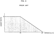
- FIG. 6 is an explanatory drawing showing regulations concerning an assist ratio of a motor for an electrically assisted bicycle.
- an assist ratio of a motor for an electrically assisted bicycle is regulated according to a speed. For example, at a bicycle speed of 0 km/h to 10 km/h, an assist ratio is mandated to be 2 or less with respect to a pedal force. From 10 km/h to 24 km/h, an upper limit to an assist ratio is lowered with an increase in speed. At a speed of 24 km/h or higher, electric motor assist is prohibited.
- a motor with a constant output capability is conventionally used.
- An input current to the motor is controlled according to a speed and the output of the motor is set according to a pedal force, so that an assist ratio is controlled according to a speed.
- an electric motor with an output capability of 26 V is used.
- An amount of current inputted to the electric motor and the duty of power input are adjusted, and the output value of the electric motor is controlled according to a pedal force.
- an electric motor having large motor characteristics is used, an amount of current passing through the electric motor is controlled according to a speed to reduce apparent motor characteristics, and the output value of the electric motor is controlled according to a pedal force.
- the motor output is controlled to obtain an assist ratio in compliance with the regulations (see Patent Literature 1).
- Patent Literature 1 Japanese Patent Laid-Open No. 10-59260
- an object of a method for controlling a motor for an electrically assisted bicycle according to the present invention is to prevent an electric motor from providing excessive assistance.
- a method for controlling a motor for an electrically assisted bicycle includes: estimating the relationship between a vehicle speed and a pedal force under constant riding conditions; calculating an input voltage to the motor beforehand according to the vehicle speed such that an assist ratio is compliant with a standard for the vehicle speed; measuring the vehicle speed; providing motor assistance according to the pedal force while fixing, to a first voltage, the input voltage to the motor in a low-speed region where a constant assist ratio is specified by the standard; changing the input voltage from a second voltage to a third voltage in proportion to the vehicle speed in a vehicle-speed region serving as a high-speed gradual decrease part of the standard; and stopping a motor output by fixing the input voltage to the third voltage in a region having a higher vehicle speed than the high-speed gradual decrease part, characterized in that the first voltage is a maximum output voltage of the motor, and the third voltage allows the motor output to become 0 at a maximum vehicle speed of the high-speed gradual decrease part.
- the vehicle speed may be determined according to the rotational speed of one of a wheel and a pedal of the bicycle.
- a device for controlling a motor for an electrically assisted bicycle includes: a motor that assists driving of the bicycle; a speed sensor that measures a vehicle speed; and a voltage control unit that controls an input voltage to the motor according to the vehicle speed, characterized in that a motor output is controlled by the input voltage to an output satisfying an assist ratio specified by a standard, according to a pedal force estimated from the vehicle speed.
- the speed sensor may include a rotation sensor that measures the rotational speed of one of a wheel and a pedal of the bicycle or the rotational speed of the motor, and the vehicle speed may be calculated from the rotational speed.
- the characteristic of an electric motor is controlled by an input voltage, thereby preventing the electric motor from providing excessive assistance.
- an upper limit to an assist ratio of an electric motor is regulated according to a speed by predetermined standards of regulations.
- the assist ratio is controlled by controlling a motor output by means of an electric motor with a constant output capability.
- a motor output is controlled according to an amount of input current and a pedal force, whereas in the present invention, a motor output is controlled by an input voltage.
- a maximum pedal force is estimated for each speed range under predetermined riding conditions, a maximum motor output compliant with the regulations at the estimated pedal force is calculated, and an input voltage is controlled such that each speed range has the calculated motor output. Since a motor output is controlled in this way and assistance is provided according to a motor output calculated for each speed range, an assist ratio can be kept compliant with the regulations at the estimated pedal force.
- FIGS. 1 to 5 a specific example of a method for controlling a motor for an electrically assisted bicycle according to the present invention will be described in detail.
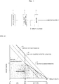
- FIG. 1 illustrates the configuration of a control device of a motor for an electrically assisted bicycle according to the present invention.
- FIG. 2 is an explanatory drawing showing states of control of motor characteristics according to the present invention.
- reference numeral 9 denotes regulations, an example of standards regulating an assist ratio.
- the assist ratio of the motor needs to be set within the range of the regulations 9 with respect to a pedal force.
- a motor output for securing an assist ratio in a high-speed range is obtained by using an electric motor having a larger motor characteristic than a reduction rate of a high-speed gradual decrease part that is set at an upper limit value in the range of 10 km/h to 24 km/h of the regulations 9.
- a typical electric motor with an output of 26 V is conventionally used.
- an assist ratio is regulated by a vehicle speed and thus a speed sensor 1 monitors the speed of a bicycle.
- an input voltage 4 to a motor 3 is set to 26 V and an apparent motor characteristic is controlled to the motor characteristic 6 by a voltage control unit 2.
- the motor output is made proportionate to a pedal force according to the motor characteristic 6 on which the input voltage 4 is set to 26 V.
- the assist ratio can be doubled from the pedal force.
- the input voltage 4 is increased from 20 V according to a speed.
- the voltage control unit 2 is controlled to set the input voltage 4 to 26 V and the apparent motor characteristic is set to a motor characteristic 8.
- the input voltage of the motor 3 is increased with a speed to control the motor characteristic, enabling a motor output corresponding to the speed in accordance with the high-speed gradual decrease part of the regulations 9.
- the regulations 9 can be satisfied by providing assistance using the motor 3 having an apparent output characteristic of 20 V (motor characteristic 7) with respect to a maximum pedal force estimated under the predetermined riding conditions.
- the input voltage is adjusted so as to set the motor output to 20 V.
- the input voltage 4 is set to 26 V and the assist ratio is set to 0.
- the input voltage 4 is kept at 26 V and the assistance of the electric motor is stopped.
- the input voltage 4 of the motor 3 is controlled according to a speed, achieving the same effect as in the case where an assist ratio is controlled by using a motor having a motor characteristic 10 in compliance with the regulations serving as standards.
- the input voltage is increased in proportion to a speed to obtain an assist ratio in compliance with the standards.
- an input voltage may be reduced with an increase in speed to obtain an assist ratio compliant with the standards.
- FIG. 3 is an explanatory drawing illustrating a conventional configuration for controlling a motor output.
- FIG. 3(a) is a circuit diagram illustrating the control configuration of a motor output.
- FIG. 3(b) shows the relationship between a current inputted to an electric motor and output torque.
- FIG. 3(c) illustrates the relationship between an input current and a motor characteristic.
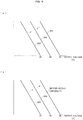
- FIG. 4 shows the relationship between a motor output and an assist ratio.
- FIG. 4(a) shows the relationship between a speed and a required assist ratio.
- FIG. 4(b) shows the relationship between a pedal force and a motor output.
- a motor 33 is connected to a power supply 34, and a current sensor 35 and a current control circuit 36 are connected in series between the motor 33 and the power supply 34.
- the current control circuit 36 includes a plurality of units arranged in parallel, each of which includes a switch and a resistor arranged in series.
- a current value inputted to the motor 33 is measured by the current sensor 35 and the switches of the current control circuit 36 are opened or closed to obtain a predetermined current value.
- the motor characteristic increases or decreases in proportion to an input current.
- the output motor characteristic is controlled depending on the ratio of an input current to a maximum input current.
- the maximum input current is 100%.
- FIG. 3(c) shows current characteristics at an input current of 40% and an input current of 80% relative to the maximum input current.
- the motor characteristic is controlled by using an input current according to a vehicle speed, so that an assist ratio is controlled according to a speed as shown in FIG. 4(a) .
- the current control circuit 36 is controlled to set the input current of the motor 33 to 80% of the maximum input current, thereby controlling the output of the motor 33 relative to a pedal force as shown in FIG. 4(b) .
- the current control circuit 36 is controlled to set the input current of the motor 33 to 40% of the maximum input current, thereby controlling the output of the motor 33 relative to a pedal force as shown in FIG. 4(b) .
- a motor characteristic is controlled according to an input voltage.
- an upper limit to an input voltage does not extremely increase an assist ratio.
- FIG. 5 is an explanatory drawing showing a change of a motor output depending on an input voltage according to the present invention.
- the input voltage is controlled to a lower voltage, for example, from 26 V to 24 V or from 24 V to 22 V, which does not extremely increase an assist ratio ( FIG. 5(a) ).
- the input voltage is controlled to a higher voltage, for example, from 22 V to 24 V or from 24 V to 26 V.
- the motor 3 with a corresponding output capability is used. Thus, even when the input voltage increases, the motor output is not increased any more.
- an assist ratio is not excessively increased.
- the motor 3 with an output capability of 26 V the input voltage is controlled to 26 V at a vehicle speed of 24 km/h; meanwhile, the assistance is stopped.
- the voltage control unit 2 increases the voltage, allowing the input voltage to exceed 26 V.
- the motor 3 has an output capability of 26 V and thus the motor output does not exceed 26 V.
- the assistance is stopped. Therefore, even if an input voltage is erroneously recognized, an assist ratio is not excessively increased, thereby keeping safe riding.
- the motor with an output capability of 26 V is used.
- the input voltage is controlled to 26 V.
- the input voltage is then increased from 20 V in proportion to a speed and reaches 26 V at the maximum vehicle speed where assistance is accepted by the regulations serving as standards.
- the output capability of the motor is not limited to 26 V and can be freely determined as long as the assist ratio can be regulated by the regulations.
- the input voltage can be determined according to a speed.
- the assist ratio is 0 at a vehicle speed of 24 km/h.
- the assist ratio may become 0 at a vehicle speed lower than 24 km/h.
- the input voltage can be controlled such that the assist ratio has a margin with respect to a standard upper limit value.
- a rotational speed sensor may be used to calculate the rotational speed of a wheel or pedal or the rotational speed of the motor to calculate a vehicle speed based on the rotational speed.
- the present invention is useful for a method and device for controlling a motor for an electrically assisted bicycle which can prevent an electric motor from providing excessive assistance and allows the electric motor to assist the output of a bicycle.
Landscapes
- Engineering & Computer Science (AREA)
- Chemical & Material Sciences (AREA)
- Combustion & Propulsion (AREA)
- Transportation (AREA)
- Mechanical Engineering (AREA)
- Electric Propulsion And Braking For Vehicles (AREA)
Description
- The present invention relates to a method and device for controlling a motor for an electrically assisted bicycle which assist the output of a bicycle by means of an electric motor.
- The published Japanese patent application
JP 2007 223579 A claims - An electrically assisted bicycle generates a bicycle output, which is a driving force of a bicycle, by integrating the output of an electric motor with a pedal force generated by pedaling. The electric motor varies in output according to a pedal force and controls an assist ratio.
- Referring to
FIG. 6 , a conventional method for controlling an electric motor will be described below. -
FIG. 6 is an explanatory drawing showing regulations concerning an assist ratio of a motor for an electrically assisted bicycle. - As shown in
FIG. 6 , an assist ratio of a motor for an electrically assisted bicycle is regulated according to a speed. For example, at a bicycle speed of 0 km/h to 10 km/h, an assist ratio is mandated to be 2 or less with respect to a pedal force. From 10 km/h to 24 km/h, an upper limit to an assist ratio is lowered with an increase in speed. At a speed of 24 km/h or higher, electric motor assist is prohibited. - To ensure compliance with the regulations concerning an assist ratio, a motor with a constant output capability is conventionally used. An input current to the motor is controlled according to a speed and the output of the motor is set according to a pedal force, so that an assist ratio is controlled according to a speed.
- For example, an electric motor with an output capability of 26 V is used. An amount of current inputted to the electric motor and the duty of power input are adjusted, and the output value of the electric motor is controlled according to a pedal force. Specifically, an electric motor having large motor characteristics is used, an amount of current passing through the electric motor is controlled according to a speed to reduce apparent motor characteristics, and the output value of the electric motor is controlled according to a pedal force. Thus, the motor output is controlled to obtain an assist ratio in compliance with the regulations (see Patent Literature 1).
- Patent Literature 1: Japanese Patent Laid-Open No.
10-59260 - In a conventional method for controlling an electric motor, during the control of a current amount, an increase or decrease in current amount is adjusted while an actual current amount is measured by a current sensor. Thus, in the case where a measured current amount is smaller than an actual current amount due to failures of the current sensor, the current amount increases more than necessary, leading to excessive assistance. Particularly, excessive assistance causes an extremely high speed, leading to unsafe riding.
- In order to solve the problem, an object of a method for controlling a motor for an electrically assisted bicycle according to the present invention is to prevent an electric motor from providing excessive assistance.
- In order to attain the object, a method for controlling a motor for an electrically assisted bicycle according to the present invention includes: estimating the relationship between a vehicle speed and a pedal force under constant riding conditions; calculating an input voltage to the motor beforehand according to the vehicle speed such that an assist ratio is compliant with a standard for the vehicle speed; measuring the vehicle speed; providing motor assistance according to the pedal force while fixing, to a first voltage, the input voltage to the motor in a low-speed region where a constant assist ratio is specified by the standard; changing the input voltage from a second voltage to a third voltage in proportion to the vehicle speed in a vehicle-speed region serving as a high-speed gradual decrease part of the standard; and stopping a motor output by fixing the input voltage to the third voltage in a region having a higher vehicle speed than the high-speed gradual decrease part, characterized in that the first voltage is a maximum output voltage of the motor, and the third voltage allows the motor output to become 0 at a maximum vehicle speed of the high-speed gradual decrease part.
- The vehicle speed may be determined according to the rotational speed of one of a wheel and a pedal of the bicycle.
- A device for controlling a motor for an electrically assisted bicycle according to the present invention, includes: a motor that assists driving of the bicycle; a speed sensor that measures a vehicle speed; and a voltage control unit that controls an input voltage to the motor according to the vehicle speed, characterized in that a motor output is controlled by the input voltage to an output satisfying an assist ratio specified by a standard, according to a pedal force estimated from the vehicle speed.
- The speed sensor may include a rotation sensor that measures the rotational speed of one of a wheel and a pedal of the bicycle or the rotational speed of the motor, and the vehicle speed may be calculated from the rotational speed.
- As has been discussed, the characteristic of an electric motor is controlled by an input voltage, thereby preventing the electric motor from providing excessive assistance.
-
- [
FIG. 1] FIG. 1 illustrates the configuration of a control device of a motor for an electrically assisted bicycle according to the present invention. - [
FIG. 2] FIG. 2 is an explanatory drawing showing states of control of motor characteristics according to the present invention. - [
FIG. 3] FIG. 3 is an explanatory drawing illustrating a conventional configuration for controlling a motor output. - [
FIG. 4] FIG. 4 shows the relationship between a motor output and an assist ratio. - [
FIG. 5] FIG. 5 is an explanatory drawing showing a change of a motor output depending on an input voltage according to the present invention. - [
FIG. 6] FIG. 6 is an explanatory drawing showing regulations concerning an assist ratio of a motor for an electrically assisted bicycle. - As has been discussed, an upper limit to an assist ratio of an electric motor is regulated according to a speed by predetermined standards of regulations. The assist ratio is controlled by controlling a motor output by means of an electric motor with a constant output capability. Conventionally, a motor output is controlled according to an amount of input current and a pedal force, whereas in the present invention, a motor output is controlled by an input voltage. Furthermore, a maximum pedal force is estimated for each speed range under predetermined riding conditions, a maximum motor output compliant with the regulations at the estimated pedal force is calculated, and an input voltage is controlled such that each speed range has the calculated motor output. Since a motor output is controlled in this way and assistance is provided according to a motor output calculated for each speed range, an assist ratio can be kept compliant with the regulations at the estimated pedal force.
- Referring to
FIGS. 1 to 5 , a specific example of a method for controlling a motor for an electrically assisted bicycle according to the present invention will be described in detail. -
FIG. 1 illustrates the configuration of a control device of a motor for an electrically assisted bicycle according to the present invention.FIG. 2 is an explanatory drawing showing states of control of motor characteristics according to the present invention. - In
FIG. 2 ,reference numeral 9 denotes regulations, an example of standards regulating an assist ratio. The assist ratio of the motor needs to be set within the range of theregulations 9 with respect to a pedal force. - According to the present invention, as indicated by a
motor characteristic 6, a motor output for securing an assist ratio in a high-speed range is obtained by using an electric motor having a larger motor characteristic than a reduction rate of a high-speed gradual decrease part that is set at an upper limit value in the range of 10 km/h to 24 km/h of theregulations 9. For example, a typical electric motor with an output of 26 V is conventionally used. - First, an assist ratio is regulated by a vehicle speed and thus a
speed sensor 1 monitors the speed of a bicycle. - Assuming that a motor with an output capability of 26 V is used, at a vehicle speed of 0 km/h to 10 km/h, an
input voltage 4 to amotor 3 is set to 26 V and an apparent motor characteristic is controlled to themotor characteristic 6 by avoltage control unit 2. The motor output is made proportionate to a pedal force according to themotor characteristic 6 on which theinput voltage 4 is set to 26 V. Thus, the assist ratio can be doubled from the pedal force. - At a vehicle speed of 10 km/h to 24 km/h, the
input voltage 4 is increased from 20 V according to a speed. At a vehicle speed of 24 km/h, thevoltage control unit 2 is controlled to set theinput voltage 4 to 26 V and the apparent motor characteristic is set to amotor characteristic 8. The input voltage of themotor 3 is increased with a speed to control the motor characteristic, enabling a motor output corresponding to the speed in accordance with the high-speed gradual decrease part of theregulations 9. At a vehicle speed of 10 km/h, theregulations 9 can be satisfied by providing assistance using themotor 3 having an apparent output characteristic of 20 V (motor characteristic 7) with respect to a maximum pedal force estimated under the predetermined riding conditions. Thus, at a vehicle speed of 10 km/h, the input voltage is adjusted so as to set the motor output to 20 V. At a vehicle speed of 24 km/h, theinput voltage 4 is set to 26 V and the assist ratio is set to 0. In a speed range of 24 km/h or higher, theinput voltage 4 is kept at 26 V and the assistance of the electric motor is stopped. - The
input voltage 4 of themotor 3 is controlled according to a speed, achieving the same effect as in the case where an assist ratio is controlled by using a motor having a motor characteristic 10 in compliance with the regulations serving as standards. - In this explanation, the input voltage is increased in proportion to a speed to obtain an assist ratio in compliance with the standards. For some characteristics of a used motor, an input voltage may be reduced with an increase in speed to obtain an assist ratio compliant with the standards.
- A conventional method for controlling a motor output according to an input current will be specifically described below for comparison with the effect of the present invention.
-
FIG. 3 is an explanatory drawing illustrating a conventional configuration for controlling a motor output.FIG. 3(a) is a circuit diagram illustrating the control configuration of a motor output.FIG. 3(b) shows the relationship between a current inputted to an electric motor and output torque.FIG. 3(c) illustrates the relationship between an input current and a motor characteristic.FIG. 4 shows the relationship between a motor output and an assist ratio.FIG. 4(a) shows the relationship between a speed and a required assist ratio.FIG. 4(b) shows the relationship between a pedal force and a motor output. - As shown in
FIG. 3(a) , in the conventional control configuration of a motor characteristic, amotor 33 is connected to apower supply 34, and acurrent sensor 35 and acurrent control circuit 36 are connected in series between themotor 33 and thepower supply 34. Thecurrent control circuit 36 includes a plurality of units arranged in parallel, each of which includes a switch and a resistor arranged in series. In the conventional motor characteristic control circuit, a current value inputted to themotor 33 is measured by thecurrent sensor 35 and the switches of thecurrent control circuit 36 are opened or closed to obtain a predetermined current value. - As shown in
FIG. 3(b) , the motor characteristic increases or decreases in proportion to an input current. Hence, as shown inFIG. 3(c) , the output motor characteristic is controlled depending on the ratio of an input current to a maximum input current. InFIG. 3(c) , the maximum input current is 100%. Furthermore,FIG. 3(c) shows current characteristics at an input current of 40% and an input current of 80% relative to the maximum input current. - The motor characteristic is controlled by using an input current according to a vehicle speed, so that an assist ratio is controlled according to a speed as shown in
FIG. 4(a) . Specifically, at A having a vehicle speed of 10 km/h or less, thecurrent control circuit 36 is controlled to set the input current of themotor 33 to 80% of the maximum input current, thereby controlling the output of themotor 33 relative to a pedal force as shown inFIG. 4(b) . At B having a vehicle speed of 10 km/h to 24 km/h, thecurrent control circuit 36 is controlled to set the input current of themotor 33 to 40% of the maximum input current, thereby controlling the output of themotor 33 relative to a pedal force as shown inFIG. 4(b) . - In the conventional method for controlling a motor characteristic according to an input current, in the event of a failure of the
current sensor 35, excessive assistance is provided, leading to unsafe riding. For example, in the case where thecurrent sensor 35 fails and detects a lower value than an actual current value, thecurrent control circuit 36 keeps raising the current value, which may increase the motor characteristic more than necessary. If the control of thecurrent control circuit 36 continues, the motor characteristic keeps rising and causes an excessive access ratio, which may lead to unsafe riding, e.g., an overspeed. - In the method and device for controlling a motor according to the present invention, as has been discussed, a motor characteristic is controlled according to an input voltage. Thus, even if the control device fails, an upper limit to an input voltage does not extremely increase an assist ratio.
- Referring to
FIG. 5 , the method and device according to the present invention will be described below.FIG. 5 is an explanatory drawing showing a change of a motor output depending on an input voltage according to the present invention. - As shown in
FIG. 5 , in the case where the voltage sensor of thevoltage control unit 2 fails and detects a higher voltage than an actual voltage, the input voltage is controlled to a lower voltage, for example, from 26 V to 24 V or from 24 V to 22 V, which does not extremely increase an assist ratio (FIG. 5(a) ). In the case where the voltage sensor fails and detects a lower voltage than an actual voltage, the input voltage is controlled to a higher voltage, for example, from 22 V to 24 V or from 24 V to 26 V. In order to obtain an assist ratio of 0 at a motor output corresponding to a vehicle speed of 24 km/h, themotor 3 with a corresponding output capability is used. Thus, even when the input voltage increases, the motor output is not increased any more. Thus, even if an input voltage is erroneously recognized, an assist ratio is not excessively increased. Specifically, as has been discussed, in the case where themotor 3 with an output capability of 26 V is used, the input voltage is controlled to 26 V at a vehicle speed of 24 km/h; meanwhile, the assistance is stopped. Thus, in the case where the voltage sensor detects a lower voltage than an actual voltage, thevoltage control unit 2 increases the voltage, allowing the input voltage to exceed 26 V. Even in this case, themotor 3 has an output capability of 26 V and thus the motor output does not exceed 26 V. At a vehicle speed of at least 24 km/h, the assistance is stopped. Therefore, even if an input voltage is erroneously recognized, an assist ratio is not excessively increased, thereby keeping safe riding. - In this explanation, the motor with an output capability of 26 V is used. At a maximum vehicle speed or lower where a constant assist ratio is accepted, the input voltage is controlled to 26 V. The input voltage is then increased from 20 V in proportion to a speed and reaches 26 V at the maximum vehicle speed where assistance is accepted by the regulations serving as standards. The output capability of the motor is not limited to 26 V and can be freely determined as long as the assist ratio can be regulated by the regulations. Furthermore, the input voltage can be determined according to a speed.
- In this example, the assist ratio is 0 at a vehicle speed of 24 km/h. In order to reliably regulate the assist ratio within the standards, the assist ratio may become 0 at a vehicle speed lower than 24 km/h. Furthermore, in each vehicle speed range, the input voltage can be controlled such that the assist ratio has a margin with respect to a standard upper limit value.
- Although a vehicle speed is measured by the speed sensor, a rotational speed sensor may be used to calculate the rotational speed of a wheel or pedal or the rotational speed of the motor to calculate a vehicle speed based on the rotational speed.
- The present invention is useful for a method and device for controlling a motor for an electrically assisted bicycle which can prevent an electric motor from providing excessive assistance and allows the electric motor to assist the output of a bicycle.
Claims (4)
- A method for controlling a motor (3) for an electrically assisted bicycle, comprising:estimating a relationship between a vehicle speed and a pedal force under constant riding conditions;calculating an input voltage (4) to the motor (3) beforehand according to the vehicle speed such that an assist ratio is compliant with a standard for the vehicle speed;measuring the vehicle speed;providing motor assistance according to the pedal force while fixing, to a first voltage, the input voltage (4) to the motor (3) in a low-speed region where a constant assist ratio is specified by the standard;changing the input voltage (4) from a second voltage to a third voltage in proportion to the vehicle speed in a vehicle-speed region serving as a high-speed gradual decrease part of the standard; andstopping a motor output (5) by fixing the input voltage (4) to the third voltage in a region having a higher vehicle speed than the high-speed gradual decrease part,characterized in that the first voltage is a maximum output voltage of the motor (3), and the third voltage allows the motor output (5) to become 0 at a maximum vehicle speed of the high-speed gradual decrease part.
- The method for controlling a motor (3) for an electrically assisted bicycle according to claim 1, characterized in that the vehicle speed is determined according to a rotational speed of one of a wheel and a pedal of the bicycle.
- A device for controlling a motor for an electrically assisted bicycle, comprising:a motor (3) that assists driving of the bicycle;a speed sensor (1) that measures a vehicle speed; anda voltage control unit (2) that controls an input voltage (4) to the motor (3) according to the vehicle speed, the voltage control unit (2) being adapted to fix, to a first voltage, the input voltage (4) to the motor (3) in a low-speed region where a constant assist ratio is specified by a standard for the vehicle speed, the voltage control unit (2) further being adapted to change the input voltage (4) from a second voltage to a third voltage in proportion to the vehicle speed in a vehicle-speed region serving as a high-speed gradual decrease part of the standard,characterized in that a motor output (5) is controlled by the input voltage (4) to an output satisfying an assist ratio specified by a standard, according to a pedal force estimated from the vehicle speed, wherein the first voltage is a maximum output voltage of the motor (3), and the third voltage allows the motor output (5) to become 0 at a maximum vehicle speed of the high-speed gradual decrease part.
- The device for controlling a motor for an electrically assisted bicycle according to claim 3, characterized in that the speed sensor (1) includes a rotation sensor that measures a rotational speed of one of a wheel and a pedal of the bicycle or a rotational speed of the motor (3), and the vehicle speed is calculated from the rotational speed.
Applications Claiming Priority (2)
| Application Number | Priority Date | Filing Date | Title |
|---|---|---|---|
| JP2010060038A JP4841676B2 (en) | 2010-03-17 | 2010-03-17 | Motor control method for electric assist bicycle and motor control apparatus for electric assist bicycle |
| PCT/JP2011/000502 WO2011114612A1 (en) | 2010-03-17 | 2011-01-31 | Method and device for controlling motor for electrically assisted bicycle |
Publications (3)
| Publication Number | Publication Date |
|---|---|
| EP2548795A1 EP2548795A1 (en) | 2013-01-23 |
| EP2548795A4 EP2548795A4 (en) | 2013-05-08 |
| EP2548795B1 true EP2548795B1 (en) | 2017-01-04 |
Family
ID=44648728
Family Applications (1)
| Application Number | Title | Priority Date | Filing Date |
|---|---|---|---|
| EP11755805.6A Not-in-force EP2548795B1 (en) | 2010-03-17 | 2011-01-31 | Method and device for controlling motor for electrically assisted bicycle |
Country Status (3)
| Country | Link |
|---|---|
| EP (1) | EP2548795B1 (en) |
| JP (1) | JP4841676B2 (en) |
| WO (1) | WO2011114612A1 (en) |
Families Citing this family (4)
| Publication number | Priority date | Publication date | Assignee | Title |
|---|---|---|---|---|
| JP5882400B2 (en) * | 2014-02-04 | 2016-03-09 | ヤマハ発動機株式会社 | Electric auxiliary vehicle and assist ratio control device |
| JP6927902B2 (en) * | 2018-02-09 | 2021-09-01 | 株式会社シマノ | Control device for human-powered vehicles |
| JP6993272B2 (en) * | 2018-03-22 | 2022-01-13 | 株式会社シマノ | Control device for human-powered vehicles |
| FR3099127B1 (en) * | 2019-07-25 | 2021-11-26 | Bellatrix | Method for developing a torque command supplied by an engine of an electrically assisted vehicle, computer program and vehicle implementing such a method |
Citations (2)
| Publication number | Priority date | Publication date | Assignee | Title |
|---|---|---|---|---|
| JPH08230754A (en) * | 1995-02-28 | 1996-09-10 | Sanyo Electric Co Ltd | Motor assisted bicycle |
| JP2001199378A (en) * | 2000-01-19 | 2001-07-24 | Honda Motor Co Ltd | Electric assisted bicycle |
Family Cites Families (10)
| Publication number | Priority date | Publication date | Assignee | Title |
|---|---|---|---|---|
| JPH0891280A (en) * | 1994-09-28 | 1996-04-09 | Suzuki Motor Corp | Electric bicycle and power control method thereof |
| JPH0976983A (en) * | 1995-09-08 | 1997-03-25 | Toshio Akao | Motor assisted bicycle |
| US5798702A (en) * | 1996-04-18 | 1998-08-25 | Suzuki Motor Corporation | Residual battery capacity display device for electric vehicle |
| JP3315872B2 (en) | 1996-08-20 | 2002-08-19 | 三洋電機株式会社 | Torque limiting device for electric vehicle motor |
| US5922035A (en) * | 1997-12-03 | 1999-07-13 | Winston Hsu | Fuzzy logic control system for electrical aided vehicle |
| JPH11278360A (en) * | 1998-03-26 | 1999-10-12 | Matsushita Electric Ind Co Ltd | Control method for vehicle with auxiliary power unit |
| JP3141344B2 (en) * | 1999-04-05 | 2001-03-05 | 本田技研工業株式会社 | Bicycle with drive assist device |
| JP2002240773A (en) * | 2001-02-14 | 2002-08-28 | Yamaha Motor Co Ltd | Auxiliary power control device for electric assist vehicle |
| JP4024091B2 (en) * | 2002-06-21 | 2007-12-19 | 松下電器産業株式会社 | Vehicle with auxiliary power |
| JP2007223579A (en) * | 2006-02-22 | 2007-09-06 | Sofutoronikusu Kk | Bicycle with electric motor and program for controlling it |
-
2010
- 2010-03-17 JP JP2010060038A patent/JP4841676B2/en not_active Expired - Fee Related
-
2011
- 2011-01-31 WO PCT/JP2011/000502 patent/WO2011114612A1/en not_active Ceased
- 2011-01-31 EP EP11755805.6A patent/EP2548795B1/en not_active Not-in-force
Patent Citations (2)
| Publication number | Priority date | Publication date | Assignee | Title |
|---|---|---|---|---|
| JPH08230754A (en) * | 1995-02-28 | 1996-09-10 | Sanyo Electric Co Ltd | Motor assisted bicycle |
| JP2001199378A (en) * | 2000-01-19 | 2001-07-24 | Honda Motor Co Ltd | Electric assisted bicycle |
Non-Patent Citations (1)
| Title |
|---|
| MASATOKU KOKAYU: "Regulations on Electric Bicycles in Japan", CONFERENCE OF SAFETY POPULARIZATION FOR ELECTRIC ASSIST BICYCLES, 1 April 2001 (2001-04-01) * |
Also Published As
| Publication number | Publication date |
|---|---|
| JP4841676B2 (en) | 2011-12-21 |
| EP2548795A1 (en) | 2013-01-23 |
| EP2548795A4 (en) | 2013-05-08 |
| WO2011114612A1 (en) | 2011-09-22 |
| JP2011189914A (en) | 2011-09-29 |
Similar Documents
| Publication | Publication Date | Title |
|---|---|---|
| EP2583879B1 (en) | Electronic control device | |
| JP4539218B2 (en) | Electric power steering device | |
| KR100241513B1 (en) | Controller for Electric Vehicle | |
| EP2022701B1 (en) | Electric power steering device | |
| US20090079375A1 (en) | Motor controller and electric power steering apparatus | |
| EP3031698B1 (en) | Electric power steering apparatus and controlling method | |
| EP3299231B1 (en) | Electrically powered brake device | |
| US11088645B2 (en) | Control device of multi-phase rotating machine | |
| CN102248900B (en) | Methods and system for motor torque control for vehicles when current sensor is not operating properly | |
| JP6396180B2 (en) | Drive control device for wheel independent drive type vehicle | |
| US9428079B2 (en) | Electric vehicle | |
| KR102326629B1 (en) | Control device and method for traction control for an electric drive system | |
| EP3415360A1 (en) | Drive control device for vehicle with independently driven wheels | |
| US20220194464A1 (en) | Method for controlling a steer-by-wire steering system and steer-by-wire steering system for a motor vehicle | |
| JP2017005899A (en) | Drive control device for wheel independent drive type vehicle | |
| EP2548795A1 (en) | Method and device for controlling motor for electrically assisted bicycle | |
| EP2818354A1 (en) | Drive control device for vehicle | |
| JP7089868B2 (en) | Electric motor device and electric brake device | |
| US20190217841A1 (en) | Electric brake device | |
| JP2017169247A (en) | Drive control device for wheel independent drive type vehicle | |
| JP4483522B2 (en) | Electric power steering apparatus and power supply system | |
| US7664583B2 (en) | Electric power assisted steering apparatus | |
| EP4406108B1 (en) | Motor control system for determining an operating point for controlling an electric motor | |
| JP4415043B2 (en) | Motor control device | |
| JP2016037237A (en) | Vehicle control system |
Legal Events
| Date | Code | Title | Description |
|---|---|---|---|
| PUAI | Public reference made under article 153(3) epc to a published international application that has entered the european phase |
Free format text: ORIGINAL CODE: 0009012 |
|
| 17P | Request for examination filed |
Effective date: 20120910 |
|
| AK | Designated contracting states |
Kind code of ref document: A1 Designated state(s): AL AT BE BG CH CY CZ DE DK EE ES FI FR GB GR HR HU IE IS IT LI LT LU LV MC MK MT NL NO PL PT RO RS SE SI SK SM TR |
|
| A4 | Supplementary search report drawn up and despatched |
Effective date: 20130408 |
|
| RIC1 | Information provided on ipc code assigned before grant |
Ipc: B62M 6/45 20100101AFI20130402BHEP Ipc: B62M 6/50 20100101ALI20130402BHEP |
|
| DAX | Request for extension of the european patent (deleted) | ||
| GRAP | Despatch of communication of intention to grant a patent |
Free format text: ORIGINAL CODE: EPIDOSNIGR1 |
|
| INTG | Intention to grant announced |
Effective date: 20160725 |
|
| GRAS | Grant fee paid |
Free format text: ORIGINAL CODE: EPIDOSNIGR3 |
|
| STAA | Information on the status of an ep patent application or granted ep patent |
Free format text: STATUS: GRANT OF PATENT IS INTENDED |
|
| GRAA | (expected) grant |
Free format text: ORIGINAL CODE: 0009210 |
|
| STAA | Information on the status of an ep patent application or granted ep patent |
Free format text: STATUS: THE PATENT HAS BEEN GRANTED |
|
| AK | Designated contracting states |
Kind code of ref document: B1 Designated state(s): AL AT BE BG CH CY CZ DE DK EE ES FI FR GB GR HR HU IE IS IT LI LT LU LV MC MK MT NL NO PL PT RO RS SE SI SK SM TR |
|
| REG | Reference to a national code |
Ref country code: GB Ref legal event code: FG4D |
|
| REG | Reference to a national code |
Ref country code: CH Ref legal event code: EP |
|
| REG | Reference to a national code |
Ref country code: AT Ref legal event code: REF Ref document number: 858931 Country of ref document: AT Kind code of ref document: T Effective date: 20170115 |
|
| REG | Reference to a national code |
Ref country code: IE Ref legal event code: FG4D |
|
| REG | Reference to a national code |
Ref country code: DE Ref legal event code: R096 Ref document number: 602011034053 Country of ref document: DE |
|
| REG | Reference to a national code |
Ref country code: LT Ref legal event code: MG4D Ref country code: NL Ref legal event code: MP Effective date: 20170104 |
|
| PG25 | Lapsed in a contracting state [announced via postgrant information from national office to epo] |
Ref country code: BE Free format text: LAPSE BECAUSE OF NON-PAYMENT OF DUE FEES Effective date: 20170131 |
|
| REG | Reference to a national code |
Ref country code: AT Ref legal event code: MK05 Ref document number: 858931 Country of ref document: AT Kind code of ref document: T Effective date: 20170104 |
|
| PG25 | Lapsed in a contracting state [announced via postgrant information from national office to epo] |
Ref country code: NL Free format text: LAPSE BECAUSE OF FAILURE TO SUBMIT A TRANSLATION OF THE DESCRIPTION OR TO PAY THE FEE WITHIN THE PRESCRIBED TIME-LIMIT Effective date: 20170104 |
|
| PG25 | Lapsed in a contracting state [announced via postgrant information from national office to epo] |
Ref country code: GR Free format text: LAPSE BECAUSE OF FAILURE TO SUBMIT A TRANSLATION OF THE DESCRIPTION OR TO PAY THE FEE WITHIN THE PRESCRIBED TIME-LIMIT Effective date: 20170405 Ref country code: FI Free format text: LAPSE BECAUSE OF FAILURE TO SUBMIT A TRANSLATION OF THE DESCRIPTION OR TO PAY THE FEE WITHIN THE PRESCRIBED TIME-LIMIT Effective date: 20170104 Ref country code: NO Free format text: LAPSE BECAUSE OF FAILURE TO SUBMIT A TRANSLATION OF THE DESCRIPTION OR TO PAY THE FEE WITHIN THE PRESCRIBED TIME-LIMIT Effective date: 20170404 Ref country code: IS Free format text: LAPSE BECAUSE OF FAILURE TO SUBMIT A TRANSLATION OF THE DESCRIPTION OR TO PAY THE FEE WITHIN THE PRESCRIBED TIME-LIMIT Effective date: 20170504 Ref country code: LT Free format text: LAPSE BECAUSE OF FAILURE TO SUBMIT A TRANSLATION OF THE DESCRIPTION OR TO PAY THE FEE WITHIN THE PRESCRIBED TIME-LIMIT Effective date: 20170104 Ref country code: HR Free format text: LAPSE BECAUSE OF FAILURE TO SUBMIT A TRANSLATION OF THE DESCRIPTION OR TO PAY THE FEE WITHIN THE PRESCRIBED TIME-LIMIT Effective date: 20170104 |
|
| PG25 | Lapsed in a contracting state [announced via postgrant information from national office to epo] |
Ref country code: LV Free format text: LAPSE BECAUSE OF FAILURE TO SUBMIT A TRANSLATION OF THE DESCRIPTION OR TO PAY THE FEE WITHIN THE PRESCRIBED TIME-LIMIT Effective date: 20170104 Ref country code: PT Free format text: LAPSE BECAUSE OF FAILURE TO SUBMIT A TRANSLATION OF THE DESCRIPTION OR TO PAY THE FEE WITHIN THE PRESCRIBED TIME-LIMIT Effective date: 20170504 Ref country code: BG Free format text: LAPSE BECAUSE OF FAILURE TO SUBMIT A TRANSLATION OF THE DESCRIPTION OR TO PAY THE FEE WITHIN THE PRESCRIBED TIME-LIMIT Effective date: 20170404 Ref country code: ES Free format text: LAPSE BECAUSE OF FAILURE TO SUBMIT A TRANSLATION OF THE DESCRIPTION OR TO PAY THE FEE WITHIN THE PRESCRIBED TIME-LIMIT Effective date: 20170104 Ref country code: SE Free format text: LAPSE BECAUSE OF FAILURE TO SUBMIT A TRANSLATION OF THE DESCRIPTION OR TO PAY THE FEE WITHIN THE PRESCRIBED TIME-LIMIT Effective date: 20170104 Ref country code: RS Free format text: LAPSE BECAUSE OF FAILURE TO SUBMIT A TRANSLATION OF THE DESCRIPTION OR TO PAY THE FEE WITHIN THE PRESCRIBED TIME-LIMIT Effective date: 20170104 Ref country code: AT Free format text: LAPSE BECAUSE OF FAILURE TO SUBMIT A TRANSLATION OF THE DESCRIPTION OR TO PAY THE FEE WITHIN THE PRESCRIBED TIME-LIMIT Effective date: 20170104 Ref country code: PL Free format text: LAPSE BECAUSE OF FAILURE TO SUBMIT A TRANSLATION OF THE DESCRIPTION OR TO PAY THE FEE WITHIN THE PRESCRIBED TIME-LIMIT Effective date: 20170104 |
|
| REG | Reference to a national code |
Ref country code: CH Ref legal event code: PL |
|
| REG | Reference to a national code |
Ref country code: DE Ref legal event code: R097 Ref document number: 602011034053 Country of ref document: DE |
|
| PG25 | Lapsed in a contracting state [announced via postgrant information from national office to epo] |
Ref country code: CH Free format text: LAPSE BECAUSE OF NON-PAYMENT OF DUE FEES Effective date: 20170131 Ref country code: LI Free format text: LAPSE BECAUSE OF NON-PAYMENT OF DUE FEES Effective date: 20170131 Ref country code: IT Free format text: LAPSE BECAUSE OF FAILURE TO SUBMIT A TRANSLATION OF THE DESCRIPTION OR TO PAY THE FEE WITHIN THE PRESCRIBED TIME-LIMIT Effective date: 20170104 Ref country code: CZ Free format text: LAPSE BECAUSE OF FAILURE TO SUBMIT A TRANSLATION OF THE DESCRIPTION OR TO PAY THE FEE WITHIN THE PRESCRIBED TIME-LIMIT Effective date: 20170104 Ref country code: SK Free format text: LAPSE BECAUSE OF FAILURE TO SUBMIT A TRANSLATION OF THE DESCRIPTION OR TO PAY THE FEE WITHIN THE PRESCRIBED TIME-LIMIT Effective date: 20170104 Ref country code: EE Free format text: LAPSE BECAUSE OF FAILURE TO SUBMIT A TRANSLATION OF THE DESCRIPTION OR TO PAY THE FEE WITHIN THE PRESCRIBED TIME-LIMIT Effective date: 20170104 Ref country code: RO Free format text: LAPSE BECAUSE OF FAILURE TO SUBMIT A TRANSLATION OF THE DESCRIPTION OR TO PAY THE FEE WITHIN THE PRESCRIBED TIME-LIMIT Effective date: 20170104 |
|
| REG | Reference to a national code |
Ref country code: IE Ref legal event code: MM4A |
|
| PLBE | No opposition filed within time limit |
Free format text: ORIGINAL CODE: 0009261 |
|
| STAA | Information on the status of an ep patent application or granted ep patent |
Free format text: STATUS: NO OPPOSITION FILED WITHIN TIME LIMIT |
|
| PG25 | Lapsed in a contracting state [announced via postgrant information from national office to epo] |
Ref country code: SM Free format text: LAPSE BECAUSE OF FAILURE TO SUBMIT A TRANSLATION OF THE DESCRIPTION OR TO PAY THE FEE WITHIN THE PRESCRIBED TIME-LIMIT Effective date: 20170104 Ref country code: MC Free format text: LAPSE BECAUSE OF FAILURE TO SUBMIT A TRANSLATION OF THE DESCRIPTION OR TO PAY THE FEE WITHIN THE PRESCRIBED TIME-LIMIT Effective date: 20170104 Ref country code: LU Free format text: LAPSE BECAUSE OF NON-PAYMENT OF DUE FEES Effective date: 20170131 Ref country code: DK Free format text: LAPSE BECAUSE OF FAILURE TO SUBMIT A TRANSLATION OF THE DESCRIPTION OR TO PAY THE FEE WITHIN THE PRESCRIBED TIME-LIMIT Effective date: 20170104 |
|
| REG | Reference to a national code |
Ref country code: FR Ref legal event code: ST Effective date: 20171103 |
|
| 26N | No opposition filed |
Effective date: 20171005 |
|
| GBPC | Gb: european patent ceased through non-payment of renewal fee |
Effective date: 20170404 |
|
| PG25 | Lapsed in a contracting state [announced via postgrant information from national office to epo] |
Ref country code: FR Free format text: LAPSE BECAUSE OF NON-PAYMENT OF DUE FEES Effective date: 20170306 |
|
| REG | Reference to a national code |
Ref country code: BE Ref legal event code: MM Effective date: 20170131 |
|
| PG25 | Lapsed in a contracting state [announced via postgrant information from national office to epo] |
Ref country code: IE Free format text: LAPSE BECAUSE OF NON-PAYMENT OF DUE FEES Effective date: 20170131 Ref country code: GB Free format text: LAPSE BECAUSE OF NON-PAYMENT OF DUE FEES Effective date: 20170404 Ref country code: SI Free format text: LAPSE BECAUSE OF FAILURE TO SUBMIT A TRANSLATION OF THE DESCRIPTION OR TO PAY THE FEE WITHIN THE PRESCRIBED TIME-LIMIT Effective date: 20170104 |
|
| PG25 | Lapsed in a contracting state [announced via postgrant information from national office to epo] |
Ref country code: MT Free format text: LAPSE BECAUSE OF NON-PAYMENT OF DUE FEES Effective date: 20170131 |
|
| PG25 | Lapsed in a contracting state [announced via postgrant information from national office to epo] |
Ref country code: HU Free format text: LAPSE BECAUSE OF FAILURE TO SUBMIT A TRANSLATION OF THE DESCRIPTION OR TO PAY THE FEE WITHIN THE PRESCRIBED TIME-LIMIT; INVALID AB INITIO Effective date: 20110131 |
|
| PG25 | Lapsed in a contracting state [announced via postgrant information from national office to epo] |
Ref country code: CY Free format text: LAPSE BECAUSE OF NON-PAYMENT OF DUE FEES Effective date: 20170104 |
|
| PG25 | Lapsed in a contracting state [announced via postgrant information from national office to epo] |
Ref country code: MK Free format text: LAPSE BECAUSE OF FAILURE TO SUBMIT A TRANSLATION OF THE DESCRIPTION OR TO PAY THE FEE WITHIN THE PRESCRIBED TIME-LIMIT Effective date: 20170104 |
|
| PG25 | Lapsed in a contracting state [announced via postgrant information from national office to epo] |
Ref country code: TR Free format text: LAPSE BECAUSE OF FAILURE TO SUBMIT A TRANSLATION OF THE DESCRIPTION OR TO PAY THE FEE WITHIN THE PRESCRIBED TIME-LIMIT Effective date: 20170104 |
|
| PG25 | Lapsed in a contracting state [announced via postgrant information from national office to epo] |
Ref country code: AL Free format text: LAPSE BECAUSE OF FAILURE TO SUBMIT A TRANSLATION OF THE DESCRIPTION OR TO PAY THE FEE WITHIN THE PRESCRIBED TIME-LIMIT Effective date: 20170104 |
|
| PGFP | Annual fee paid to national office [announced via postgrant information from national office to epo] |
Ref country code: DE Payment date: 20210120 Year of fee payment: 11 |
|
| REG | Reference to a national code |
Ref country code: DE Ref legal event code: R119 Ref document number: 602011034053 Country of ref document: DE |
|
| PG25 | Lapsed in a contracting state [announced via postgrant information from national office to epo] |
Ref country code: DE Free format text: LAPSE BECAUSE OF NON-PAYMENT OF DUE FEES Effective date: 20220802 |