EP2548787A1 - Vehicle front part structure - Google Patents
Vehicle front part structure Download PDFInfo
- Publication number
- EP2548787A1 EP2548787A1 EP12174369A EP12174369A EP2548787A1 EP 2548787 A1 EP2548787 A1 EP 2548787A1 EP 12174369 A EP12174369 A EP 12174369A EP 12174369 A EP12174369 A EP 12174369A EP 2548787 A1 EP2548787 A1 EP 2548787A1
- Authority
- EP
- European Patent Office
- Prior art keywords
- cowl
- cowl cover
- lid
- opening
- part structure
- Prior art date
- Legal status (The legal status is an assumption and is not a legal conclusion. Google has not performed a legal analysis and makes no representation as to the accuracy of the status listed.)
- Granted
Links
Images


Classifications
-
- B—PERFORMING OPERATIONS; TRANSPORTING
- B62—LAND VEHICLES FOR TRAVELLING OTHERWISE THAN ON RAILS
- B62D—MOTOR VEHICLES; TRAILERS
- B62D25/00—Superstructure or monocoque structure sub-units; Parts or details thereof not otherwise provided for
- B62D25/08—Front or rear portions
- B62D25/081—Cowls
-
- B—PERFORMING OPERATIONS; TRANSPORTING
- B60—VEHICLES IN GENERAL
- B60H—ARRANGEMENTS OF HEATING, COOLING, VENTILATING OR OTHER AIR-TREATING DEVICES SPECIALLY ADAPTED FOR PASSENGER OR GOODS SPACES OF VEHICLES
- B60H1/00—Heating, cooling or ventilating devices
- B60H1/24—Ventilating devices where the heating or cooling is irrelevant
- B60H1/26—Ventilating openings in vehicle exterior; Ducts for conveying ventilating air
- B60H1/28—Ventilating openings in vehicle exterior; Ducts for conveying ventilating air the openings being situated directly in front of vehicle front window
-
- B—PERFORMING OPERATIONS; TRANSPORTING
- B60—VEHICLES IN GENERAL
- B60R—VEHICLES, VEHICLE FITTINGS, OR VEHICLE PARTS, NOT OTHERWISE PROVIDED FOR
- B60R21/00—Arrangements or fittings on vehicles for protecting or preventing injuries to occupants or pedestrians in case of accidents or other traffic risks
- B60R21/34—Protecting non-occupants of a vehicle, e.g. pedestrians
- B60R2021/343—Protecting non-occupants of a vehicle, e.g. pedestrians using deformable body panel, bodywork or components
Definitions
- the present invention has been made in view of the above problem, and an object thereof is to provide a vehicle front part structure which can realize an excellent shock absorption performance even when the height of the cowl box in the up-down direction is short.
- the wind shield lower 20 is a steel plate member which supports the lower end part of a wind shield glass 5. As shown in Fig. 2 , the wind shield lower 20 includes a frame number plate 21 on which a frame number is given. Further, an opening 6 is formed between the lid dash board upper 12 and the wind shield lower 20 as shown in Figs. 1 and 2 . In the embodiment, the wind shield lower 20 supports the wind shield glass 5 in a cantilevered structure. A shock absorbing member 7 is provided between the wind shield lower 20 and the wind shield glass 5. Further, the wind shield lower 20 includes an air conditioning air intake hole 21 which is formed at the end of the wind shield lower 20 on the side of the cabin 3 as shown in Fig. 1 .
Landscapes
- Engineering & Computer Science (AREA)
- Mechanical Engineering (AREA)
- Physics & Mathematics (AREA)
- Thermal Sciences (AREA)
- Chemical & Material Sciences (AREA)
- Combustion & Propulsion (AREA)
- Transportation (AREA)
- Body Structure For Vehicles (AREA)
- Vehicle Interior And Exterior Ornaments, Soundproofing, And Insulation (AREA)
Abstract
Description
- The present invention relates to a vehicle front part structure and, more particularly, to a vehicle front part structure of a front engine vehicle.
- As a cowl box, which is a vehicle front part structure, arranged in front of a wind shield, Japanese Unexamined Patent Application Publication No.
2003-112659 2009-255791 - Recently, a vehicle has been developed in which the engine head position is higher than that of conventional vehicles. Such a vehicle having the higher engine head position has a disadvantage that shock absorption may be difficult because the height of the cowl box in the up-down direction is designed to be short.
- The present invention has been made in view of the above problem, and an object thereof is to provide a vehicle front part structure which can realize an excellent shock absorption performance even when the height of the cowl box in the up-down direction is short.
- A first aspect of the present invention provides a vehicle front part structure including: a dashboard upper which extends frontward from an upper part of a dashboard lower which partitions an engine room and a cabin; a wind shield lower which supports a lower end of an window shield glass; a cowl top which covers an opening formed between the dashboard upper and the wind shield lower; wherein the cowl top includes a first cowl cover which covers the opening and has a cowl opening; and a second cowl cover which is provided above the first cowl cover and covers the cowl opening; the second cowl cover including: a front side surface and a rear side surface which come in contact with the first cowl cover and a design surface which connects an upper end of the front side surface to an upper end of the rear side surface, and wherein the front side surface and the rear side surface are arranged in such a manner that the front side surface and the rear side surface come close to each other as they go up and the design surface is arranged to be tilted forward.
- In the aforementioned vehicle front part structure, it is preferable that the second cowl cover is comprised of a center lid which covers the cowl opening and side lids which are respectively provided to left and right of the center lid in a vehicle width direction.
- In the aforementioned vehicle front part structure, it is preferable that the first cowl cover includes a longitudinal wall extending front-downward from a rear end of the cowl opening.
- In the aforementioned vehicle front part structure, it is preferable that the second cowl cover includes a lid opening arranged above the cowl opening and a lower end of the longitudinal wall is arranged lower than a virtual line which connects a front end of the lid opening and a front end of the wind shield lower.
- In the aforementioned vehicle front part structure, it is preferable that the longitudinal wall includes a bended bead which is formed on a rear surface of the longitudinal wall.
-
-
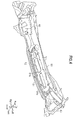
Fig. 1 is a side sectional view showing a vehicle front part structure including an air conditioning air intake hole according to an embodiment of the present invention. -
Fig. 2 is a perspective view showing a lid dashboard upper and a wind shield lower according to the embodiment of the present invention. -
Fig. 3A is a view showing a first cowl cover according to the embodiment of the present invention seen from oblique upper side.Fig. 3B is the first cowl cover according to the embodiment of the present invention seen from oblique lower side. -
Fig. 4 is a perspective view showing the state of the vehicle front part structure where the first cowl cover is assembled to the lid dashboard upper and the wind shield lower shown inFig. 2 . -
Fig. 5A is a view showing a lid frame number according to the embodiment of the present invention seen from the oblique upper side.Fig. 5B is a view showing the lid frame number according to the embodiment of the present invention seen from the oblique lower side. -
Fig. 6A is a view showing a lid wiper pivot according to the embodiment of the present invention which is seen from the upper side.Fig. 6B is a view showing the lid wiper pivot which is seen from the lower side.Fig. 6C is a view showing a lid food hinge according to the embodiment of the present invention which is seen from the upper side.Fig. 6D is a view showing the lid food hinge which is seen from the lower side. -
Fig. 7 is a perspective view showing a state of the vehicle front part structure in which the lid frame number, the lid wiper pivot and the lid food hinge are assembled to the first cowl cover. -
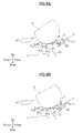
Figs. 8A and 8B are side views of the vehicle front part structure according to the embodiment of the present invention, showing the analysis result of the simulation that an object is collided with the vehicle front part structure from the upper side;Fig. 8A shows the view when the object is collided (0 sec) andFig. 8B shows the view when 3 seconds have passed from the collision. -
Figs. 9A and 9B are side views of the vehicle front part structure according to the embodiment of the present invention, showing the analysis result of the simulation that an object is collided with the vehicle front part structure from the upper side;Fig. 9A shows the view when 7 seconds have passed from the collision; andFig. 9B is the view when 10 seconds have passed from the collision. -
Fig. 10 is a side view of the vehicle front part structure according to the embodiment of the present invention, showing the analysis result of the simulation that an object is collided with the vehicle front part structure from the upper side, wherein the view shows the vehicle front part structure when 15 second have passed from the collision. - An embodiment of the present invention is described in detail with reference to the accompanying drawings. The same reference numerals are assigned to the same components in the following description, and the repeated explanation thereof is omitted.
- A vehicle front part structure 1 according to the embodiment of the present invention is a structure applied to a front engine vehicle as shown in
Fig. 1 . The vehicle front part structure 1 includes a dashboard upper 11, a lid dash board upper 12, a wind shield lower 20 and acowl top 30. - The dashboard upper 11 is a steel plate member extending frontward from the upper part of a dashboard lower 4 which partitions an
engine room 2 and acabin 3. In the embodiment, the dashboard upper 11 is fixed to the dashboard lower 4 by welding or the like. The lid dash board upper 12 is a steel plate member extending front-upward from the front end of the dashboard upper 11. The lid dash board upper 12 is fixed to the dashboard upper 11 by welding or the like in the embodiment. The dashboard upper 11 and the lid dash board upper 12 are also referred to as "a dashboard upper". - The wind shield lower 20 is a steel plate member which supports the lower end part of a
wind shield glass 5. As shown inFig. 2 , the wind shield lower 20 includes aframe number plate 21 on which a frame number is given. Further, anopening 6 is formed between the lid dash board upper 12 and the wind shield lower 20 as shown inFigs. 1 and2 . In the embodiment, the wind shield lower 20 supports thewind shield glass 5 in a cantilevered structure. Ashock absorbing member 7 is provided between the wind shield lower 20 and thewind shield glass 5. Further, the wind shield lower 20 includes an air conditioningair intake hole 21 which is formed at the end of the wind shield lower 20 on the side of thecabin 3 as shown inFig. 1 . - The
cowl top 30 is a resin member which constitutes a so-called cowl box together with the lid dash board upper 12 and the wind shield lower 20 by covering theopening 6 as shown inFig. 1 . Thecowl top 30 includes afirst cowl cover 31 and asecond cowl cover 32. - The
first cowl cover 31 is a resin member which covers theopening 6. As shown inFig. 3 , thefirst cowl cover 31 includes an air conditioningair intake hole 31a and a framenumber check opening 31b as a cowl opening formed in the vicinity of the center of thefirst cowl cover 31 in the vehicle width direction. Thefirst cowl cover 31 further includespositioning ribs 31c andpositioning clips 31d as a plurality of engaging portions provided on the lower end of thefirst cowl cover 31. The framenumber check opening 31b is positioned above the frame number plate shown inFig. 2 . Thefirst cowl cover 31 is fixed to the lid dash board upper 12 and the wind shield lower 20 by engaging thepositioning ribs 31c and the engagingclips 31d with the holes, cut-out portions or an edge of the lid dash board upper 12 and the wind shield lower 20. - As shown in
Fig. 3 , thefirst cowl cover 31 includes alongitudinal wall 31e extending front-downward from the rear end of the air conditioningair intake hole 31a. As shown inFig. 1 , the lower end of thelongitudinal wall 31e is positioned below the virtual line L which connects the front end of the air conditioning air intake hole 32a1 which is described later and the front end of the wind shield lower 20. Thelongitudinal wall 31 e functions as a water-proof rib which performs a vapor liquid separation of the external air flowing in from the air conditioning air intake hole 32a1. - The
longitudinal wall 31e includes a bended bead 31e1 formed on the rear surface of thelongitudinal wall 31e in the middle part of the rear surface in the up-down direction. - Further, the
first cowl cover 31 includes a pair ofopenings 31f which is formed at the opposite ends of thefirst cowl cover 31 in the vehicle width direction as shown inFig. 3 . Theopening 31f is positioned above a damper (not shown) and is covered by acover 40 which is a resin member, as shown inFig. 4 . If a work needs to be done on the damper, a worker removes thecover 40 and performs the work on the damper. - As shown in
Fig. 1 , thesecond cowl cover 32 is a resin member which is provided above thefirst cowl cover 31 and covers the air conditioningair intake hole 31a and the framenumber check opening 31b. The design surface of thesecond cowl cover 32 has a forward tilting shape and a recessed shape in a side view. The design surface of thesecond cowl cover 32 is also a load receiving surface which receives the load applied from the upper side of the vehicle. The height of the front end of the design surface is set to be substantially the same as or a little lower than that of the rear end of thebonnet food 8. The height of the rear end of the design surface is set higher than that of the rear end of thebonnet food 8. Thesecond cowl cover 32 includes alid frame number 32a shown inFig. 5 , alid wiper pivot 32b and alid food hinge 32c shown inFig. 6 . - The
lid frame number 32a is a center lid which constitutes a part of thesecond cowl cover 32. Thelid frame number 32a is a resin member which covers the air conditioningair intake hole 31a and the framenumber check opening 31b. As shown inFigs. 5A and 5B , thelid frame number 32a is comprised of a front side surface 32af and a rear side surface 32ab and a design surface 32au which connects upper ends of the front side surface 32af and the rear side surface 32ab. The design surface 32au is arranged above thefirst cowl cover 31 with some space between the design surface 32au and thefirst cowl cover 31. The design surface 32au has a forward tilting shape and a recessed shape in a side view. The front side surface 32af and the rear side surface 32ab are formed in such a manner that they come close to each other as they go up. In other words, thelid frame number 32a has substantially a M shape in a side view. - The
lid frame number 32a includes a plurality of air conditioning air intake holes 32a1 as a lid opening formed in the design surface 32au and positioning ribs 32a2 and engaging clips 32a3 as a plurality of engaging portions which are provided at the lower end of thelid frame member 32a. Thelid frame number 32a is fixed to thefirst cowl cover 31 as shown inFig. 7 by engaging the positioning ribs 32a2 and the engaging clips 32a3 with holes or cut-out portions formed in thefirst cowl cover 31 or the edge of thefirst cowl cover 31 on the front and rear sides of the air conditioningair intake hole 31a and the framenumber check opening 31b. When it is necessary to check the frame number, a worker removes thelid frame number 32a to see theframe number plate 2 through the framenumber check opening 31b, whereby the worker can read the frame number. - The external air taken into the cowl box from the air conditioning air intake hole 32a1 is taken into an air conditioner (not shown) through the air conditioning air intake hole 31a1 and the air conditioning
air intake hole 21. - The
lid wiper pivot 32b is a right side lid which constitutes a part of thesecond cowl cover 32 and is a resin member. As shown inFigs. 6A and 6B , thelid wiper pivot 32b is comprised of a front side surface 32bf, a rear side surface 32bb and a design surface 32bu which connects the upper ends of the front side surface 32bf and a rear side surface 32bb. The design surface 32bu is arranged above thefirst cowl cover 31 with some space between the design surface 32bu and thefirst cowl cover 31 and has a forward tilting shape and a recessed shape in a side view. Further, the front side surface 32bf and the rear side surface 32bb are formed in such a manner that they come close to each other as they go up. In other words, thelid wiper pivot 32b has substantially a M shape in a side view. - The
lid wiper pivot 32b includes positioning ribs 32b1 and engaging clips 32b2 as a plurality of engaging portions provided at the lower end of thelid wiper pivot 32b. Thelid wiper pivot 32b is fixed to thefirst cowl cover 31 as shown inFig. 7 by engaging the positioning ribs 32b1 and the engaging clips 32b2 with holes or cut-out portions formed in thefirst cowl cover 31 or the edge of thefirst cowl cover 31. - The
lid food hinge 32c is a left side lid which constitutes a part of thesecond cowl cover 32 and is a resin member. Thelid food hinge 32c is comprised of a front side surface 32cf, a rear side surface 32cb and a design surface 32cu which connects the upper ends of the front side surface 32cf and the rear side surface 32cb. The design surface 32cu is arranged above thefirst cowl cover 31 with some space between the design surface 32cu and thefirst cowl cover 31 and has a forward tilting shape and a recessed shape in a side view. Further, the front side surface 32cf and the rear side surface 32cb are formed in such a manner that they come close to each other as they go up. In other words, thelid food hinge 32c has a substantially M shape in a side view. - The
lid food hinge 32c includes positioning ribs 32c1 and engaging clips 32c2 as a plurality of engaging portions provided at the lower end of thelid food hinge 32c. Thelid food hinge 32c is fixed to thefirst cowl cover 31 as shown inFig. 7 by engaging the positioning ribs 32c1 and the engaging clips 32c2 with the holes or cut-out portions formed in thefirst cowl cover 31 or the edge of thefirst cowl cover 31. When the maintenance of the ECU (not shown) is necessary, a worker can remove thelid food hinge 32c and perform the maintenance work of the ECU. - Subsquently, the analysis result of the simulation where an object is collided with the vehicle front part structure 1 according to the embodiment of the present invention from the upper side of the vehicle is described with reference to
Figs. 8A to 10 . - Firstly, when an object O is collided with the
lid frame number 32a of thesecond cowl cover 32 of the vehicle front part structure 1 (Fig. 8A ), thesecond cowl cover 32 and thefirst cowl cover 31 are deformed by the load of the object O. The vehicle front part structure 1 according to the embodiment includes thecowl top 30 of the double structure. Thefirst cowl cover 31 and thesecond cowl cover 32 of thecowl top 30 forms a substantially C-shaped open cross section with the cowl opening (the air conditioningair intake hole 31a and the framenumber check opening 31b). The design surfaces 32au, 32bu, 32cu of thesecond cowl cover 32 which are load receiving surfaces have a forward tilting shape and a recessed shape in a side view. Further, the front side surfaces 32af, 32bf, 32cf and the rear side surfaces 32ab, 32bb, 32cb come close to each other as they go up. With this structure, thesecond cowl cover 32 is flexibly deformed in such a manner that the front side surfaces 32af, 32bf, 32cf and the rear side surfaces 32ab, 32bb, 32cb are laid down toward the center of thesecond cowl cover 32 in the front-rear direction and the design surface 32au, 32bu, 32cu are dented. Further, as thesecond cowl cover 32 has a forward tilting shape and can preferably absorb an impact when the object O is collided with the vehicle from the upper side of the vehicle when the vehicle is running. Therefore, the vehicle front part structure 1 can realize an excellent impact absorption performance at the initial stage of the collision. - Further, as the
second cowl cover 32 is comprised of three members of thelid frame number 32a, thelid wiper pivot 32b and thelid food hinge 32c, it is possible to enhance the shock absorbing performance for the collision of an object from the upper side by deforming only the member to which the load is applied, compared with a case where thesecond cowl cover 32 is comprised of just one member. - Furthermore, if the vehicle is provided with a so-called raising food, which raises the
bonnet food 8 to secure the space of theengine room 2 when the object O is collided with the vehicle front part structure 1 for reducing the impact applied to the object O, it is possible to further enhance its shock absorbing performance by making the rise of the initial acceleration of the food raising excellent. - Subsquently, the design surface 32au of the
lid frame number 32a pushes thefirst cowl cover 31 downward, making thelongitudinal wall 3 1 e to come in contact with the lid dash board upper 12 (Fig. 8B ). As thelongitudinal wall 31e extends front-downward and the bended bead 31e1 (seeFig. 1 ) is formed on the rear surface of thelongitudinal wall 31 e, thelongitudinal wall 31 e is deformed toward the front side of the lid dash board upper 12 with thelongitudinal wall 31 e being bended at the bended bead 31e1 (Fig. 9A to Fig. 10 ). - The vehicle front part structure 1 according to the embodiment of the present invention includes the
cowl top 30 of the double structure. Thefirst cowl cover 31 and thesecond cowl cover 32 of thecowl top 30 forms a substantially C shape opening with the cowl opening (the air conditioningair intake hole 31a and the framenumber check opening 31b), and the design surfaces 32au, 32bu, 32cu of thesecond cowl cover 32 which are load receiving surfaces have a forward tilting shape and a recessed shape in a side view. Further, the front side surfaces 32af, 32bf, 32cf and the rear side surfaces 32ab, 32bb, 32cb which come in contact with thefirst cowl cover 31 come close to each other as they go up. With this structure, thesecond cowl cover 32 is flexibly deformed in such a manner that the front side surfaces 32af, 32bf, 32cf and the rear side surfaces 32ab, 32bb, 32cb are laid down toward the center of thesecond cowl cover 32 in the front-rear direction the design surfaces 32au, 32bu, 32cu are dented. Further, as thesecond cowl cover 32 has a forward tilting shape and can preferably absorb an impact when the object O is collided with the vehicle from the upper side of the vehicle when the vehicle is running. Therefore, the vehicle front part structure 1 can realize an excellent shock absorbing performance at the initial stage of the collision. - As the vehicle front part structure 1 according to the embodiment of the present invention includes the
longitudinal wall 31e which functions as a water-proof rib, it is possible to realize a preferable vapor liquid separation even in a vehicle in which the speed of the external air flowing in from the air conditioning air intake hole 32a1 is higher because the height of the cowl box is designed to be short. - Further, as the
longitudinal wall 31e extends front-downward and thebended bead 31e is formed on the rear side of thelongitudinal wall 31e in the vehicle front part structure 1 according to the embodiment of the present invention, it is possible to suppress thelongitudinal wall 31e from affecting the shock absorption performance. - The embodiment of the present invention has been described as described above with reference to the accompanying drawings. However, the present invention is not limited to the embodiment of the present invention and may be modified without deviating from the spirit of the invention. For example, the
second cowl cover 32 is not limited to the structure in which thesecond cowl cover 32 is comprised of three members and may be comprised of one member, two members or more than three member. Further, the design surface of thesecond cowl cover 32 may have a structure having a forward tilting shape and straight shape in a side view. Furthermore, as the dashboard upper of the present invention, the dashboard upper 11 and the lid dash board upper 12 may be integrally formed of just one steel plate member. Furthermore, the dashboard lower and the lid dashboard upper may be integrally formed of one steel plate member. More specifically, regardless of whether the dashboard lower 4, the dashboard upper 11 and the lid dash board upper 12 are integrally formed or are separately formed, the part extending frontward from the dashboard lower which partitions the engine room and the cabin corresponds to the dashboard upper of the present invention. - As described above, the present invention can provide a vehicle front part structure which has an excellent shock absorption performance even in a vehicle in which the height of the cowl box in the up-down direction is designed to be short.
- There is provided the cowl top 30a of the vehicle front part structure 1 including a
first cowl cover 31 which covers theopening 6 and has an air conditioningair intake hole 31a and asecond cowl cover 32 which is provided above thefirst cowl cover 31 and covers the air conditioningair intake hole 31a. The second cowl cover includes a front side surface and a rear side surface which come in contact with thefirst cowl cover 31 and a design surface which connects an upper end of the front side surface to an upper end of the rear side surface. The front side surface and the rear side surface are arranged in such a manner that the front side surface and the rear side surface come close to each other as they go up and the design surface is arranged to be tilted forward.
Claims (5)
- A vehicle front part structure comprising:a dashboard upper which extends frontward from an upper part of a dashboard lower which partitions an engine room and a cabin;a wind shield lower which supports a lower end of an window shield glass;a cowl top which covers an opening formed between the dashboard upper and the wind shield lower; whereinthe cowl top includesa first cowl cover which covers the opening and has a cowl opening; anda second cowl cover which is provided above the first cowl cover and covers the cowl opening; the second cowl cover including: a front side surface and a rear side surface which come in contact with the first cowl cover and a design surface which connects an upper end of the front side surface to an upper end of the rear side surface, and whereinthe front side surface and the rear side surface are arranged in such a manner that the front side surface and the rear side surface come close to each other as they go up and the design surface is arranged to be tilted forward.
- The vehicle front part structure according to Claim 1, wherein the second cowl cover is comprised of a center lid which covers the cowl opening and side lids which are provided to left and right of the center lid in a vehicle width direction, respectively.
- The vehicle front part structure according to Claim 1 or 2, wherein the first cowl cover includes a longitudinal wall extending front-downward from a rear end of the cowl opening.
- The vehicle front part structure according to Claim 3, wherein the second cowl cover includes a lid opening arranged above the cowl opening and a lower end of the longitudinal wall is arranged lower than a virtual line which connects a front end of the lid opening and a front end of the wind shield lower.
- The vehicle front part structure according to any one of claims 1 to 4, wherein the longitudinal wall includes a bended bead which is formed on a rear surface of the longitudinal wall.
Applications Claiming Priority (1)
| Application Number | Priority Date | Filing Date | Title |
|---|---|---|---|
| JP2011146112A JP5789432B2 (en) | 2011-06-30 | 2011-06-30 | Vehicle front structure |
Publications (2)
| Publication Number | Publication Date |
|---|---|
| EP2548787A1 true EP2548787A1 (en) | 2013-01-23 |
| EP2548787B1 EP2548787B1 (en) | 2014-01-01 |
Family
ID=46581735
Family Applications (1)
| Application Number | Title | Priority Date | Filing Date |
|---|---|---|---|
| EP20120174369 Not-in-force EP2548787B1 (en) | 2011-06-30 | 2012-06-29 | Vehicle front part structure |
Country Status (2)
| Country | Link |
|---|---|
| EP (1) | EP2548787B1 (en) |
| JP (1) | JP5789432B2 (en) |
Cited By (6)
| Publication number | Priority date | Publication date | Assignee | Title |
|---|---|---|---|---|
| EP3434528A1 (en) * | 2017-07-26 | 2019-01-30 | Audi Ag | Cowl cover |
| US11110964B2 (en) * | 2019-04-11 | 2021-09-07 | Hyundai Motor Company | Front structure of vehicle body |
| FR3122148A1 (en) | 2021-04-21 | 2022-10-28 | Psa Automobiles Sa | AWNING GRILL ABLE TO BREAK IN CASE OF PEDESTRIAN IMPACT |
| CN115923941A (en) * | 2023-01-30 | 2023-04-07 | 重庆长安汽车股份有限公司 | Warm air blower pressure chamber plate structure and vehicle |
| FR3164684A1 (en) * | 2024-07-19 | 2026-01-23 | Stellantis Auto Sas | Awning grille and windshield arrangement for motor vehicles |
| EP4699834A1 (en) * | 2024-08-23 | 2026-02-25 | Traton AB | Ventilation arrangement and vehicle |
Families Citing this family (8)
| Publication number | Priority date | Publication date | Assignee | Title |
|---|---|---|---|---|
| JP6068217B2 (en) * | 2013-03-21 | 2017-01-25 | ダイハツ工業株式会社 | Vehicle front structure |
| JP5775555B2 (en) * | 2013-10-17 | 2015-09-09 | 本田技研工業株式会社 | Vehicle front structure |
| WO2015056778A1 (en) * | 2013-10-17 | 2015-04-23 | 本田技研工業株式会社 | Structure for front section of vehicle |
| JP6494217B2 (en) * | 2014-08-28 | 2019-04-03 | ダイハツ工業株式会社 | Car cowl structure |
| JP6357443B2 (en) * | 2015-05-15 | 2018-07-11 | トヨタ自動車東日本株式会社 | Cowl louva |
| JP6508180B2 (en) * | 2016-12-07 | 2019-05-08 | スズキ株式会社 | Front body structure |
| JP6565889B2 (en) * | 2016-12-19 | 2019-08-28 | トヨタ自動車株式会社 | Vehicle front structure |
| CN108556761B (en) * | 2018-06-15 | 2024-03-15 | 珠海广通汽车有限公司 | Decorative structure and car |
Citations (6)
| Publication number | Priority date | Publication date | Assignee | Title |
|---|---|---|---|---|
| JP2003112659A (en) | 2001-10-09 | 2003-04-15 | Kanto Auto Works Ltd | Outside air introducing structure for automobile |
| JP2004155351A (en) * | 2002-11-07 | 2004-06-03 | Mitsubishi Motors Corp | Vehicle front deck structure |
| JP2004217144A (en) * | 2003-01-17 | 2004-08-05 | Toyota Auto Body Co Ltd | Vehicle cowl structure |
| US7316448B2 (en) * | 2004-07-27 | 2008-01-08 | Nihon Plast Co., Ltd. | Cowl top cover |
| US20080211255A1 (en) * | 2007-03-02 | 2008-09-04 | Honda Motor Co., Ltd. | Front windshield support structure of a vehicle |
| JP2009255791A (en) | 2008-04-18 | 2009-11-05 | Suzuki Motor Corp | Cowl section structure of vehicle |
Family Cites Families (5)
| Publication number | Priority date | Publication date | Assignee | Title |
|---|---|---|---|---|
| JP4685595B2 (en) * | 2005-11-02 | 2011-05-18 | 株式会社豊田自動織機 | Vehicle cowl duct |
| JP5203815B2 (en) * | 2008-06-30 | 2013-06-05 | ダイハツ工業株式会社 | Impact force absorption structure of vehicle cowl louver |
| JP2010126068A (en) * | 2008-11-28 | 2010-06-10 | Daihatsu Motor Co Ltd | Cowl part structure of automobile |
| JP2010149547A (en) * | 2008-12-24 | 2010-07-08 | Daihatsu Motor Co Ltd | Cowl portion structure of automobile |
| JP5213827B2 (en) * | 2009-09-30 | 2013-06-19 | アイシン化工株式会社 | Vehicle cowl louver |
-
2011
- 2011-06-30 JP JP2011146112A patent/JP5789432B2/en not_active Expired - Fee Related
-
2012
- 2012-06-29 EP EP20120174369 patent/EP2548787B1/en not_active Not-in-force
Patent Citations (6)
| Publication number | Priority date | Publication date | Assignee | Title |
|---|---|---|---|---|
| JP2003112659A (en) | 2001-10-09 | 2003-04-15 | Kanto Auto Works Ltd | Outside air introducing structure for automobile |
| JP2004155351A (en) * | 2002-11-07 | 2004-06-03 | Mitsubishi Motors Corp | Vehicle front deck structure |
| JP2004217144A (en) * | 2003-01-17 | 2004-08-05 | Toyota Auto Body Co Ltd | Vehicle cowl structure |
| US7316448B2 (en) * | 2004-07-27 | 2008-01-08 | Nihon Plast Co., Ltd. | Cowl top cover |
| US20080211255A1 (en) * | 2007-03-02 | 2008-09-04 | Honda Motor Co., Ltd. | Front windshield support structure of a vehicle |
| JP2009255791A (en) | 2008-04-18 | 2009-11-05 | Suzuki Motor Corp | Cowl section structure of vehicle |
Cited By (8)
| Publication number | Priority date | Publication date | Assignee | Title |
|---|---|---|---|---|
| EP3434528A1 (en) * | 2017-07-26 | 2019-01-30 | Audi Ag | Cowl cover |
| US11110964B2 (en) * | 2019-04-11 | 2021-09-07 | Hyundai Motor Company | Front structure of vehicle body |
| FR3122148A1 (en) | 2021-04-21 | 2022-10-28 | Psa Automobiles Sa | AWNING GRILL ABLE TO BREAK IN CASE OF PEDESTRIAN IMPACT |
| CN115923941A (en) * | 2023-01-30 | 2023-04-07 | 重庆长安汽车股份有限公司 | Warm air blower pressure chamber plate structure and vehicle |
| CN115923941B (en) * | 2023-01-30 | 2024-05-10 | 重庆长安汽车股份有限公司 | Warm air blower pressure chamber plate structure and vehicle |
| FR3164684A1 (en) * | 2024-07-19 | 2026-01-23 | Stellantis Auto Sas | Awning grille and windshield arrangement for motor vehicles |
| EP4699834A1 (en) * | 2024-08-23 | 2026-02-25 | Traton AB | Ventilation arrangement and vehicle |
| WO2026043406A1 (en) * | 2024-08-23 | 2026-02-26 | Scania Cv Ab | Ventilation arrangement and vehicle |
Also Published As
| Publication number | Publication date |
|---|---|
| EP2548787B1 (en) | 2014-01-01 |
| JP2013014153A (en) | 2013-01-24 |
| JP5789432B2 (en) | 2015-10-07 |
Similar Documents
| Publication | Publication Date | Title |
|---|---|---|
| EP2548787B1 (en) | Vehicle front part structure | |
| US9126634B2 (en) | Structure for front portion of vehicle | |
| CN103129395A (en) | Instrument panel support structure of vehicle | |
| CN102510825B (en) | Structure for front section of vehicle body | |
| EP3470308B1 (en) | Automobile cowl grille structure | |
| CN106828611A (en) | The front wall side reinforcement structure of vehicle | |
| US10457238B2 (en) | Impact absorber | |
| JP4938541B2 (en) | Console box bottom mounting structure | |
| JP2009083687A (en) | Automotive front structure | |
| US7322639B2 (en) | Front structure of vehicle | |
| EP2540597A2 (en) | Front vehicle body structure with reinforced area for the mounting of hood hinges | |
| US20150353049A1 (en) | Front body structure of vehicle | |
| US10029543B2 (en) | Vehicle sun visor | |
| EP3808606B1 (en) | Vehicle front structure, and vehicle | |
| CN102039935B (en) | Front structure of vehicle body | |
| JP5109522B2 (en) | Vehicle sunroof structure | |
| US10442383B2 (en) | Impact absorber | |
| JP7743257B2 (en) | Hood inner panel and vehicle hood | |
| US9975579B2 (en) | Cowl structure | |
| JP5520079B2 (en) | Car cowl structure | |
| JP2015521970A (en) | An automobile with an additional reinforcement that can guide the deformation of the center pillar structure in the event of a side collision | |
| JP4172030B2 (en) | Automobile roof structure | |
| KR100514246B1 (en) | Combining structure of hood inner panel for automobile | |
| JP2008195149A (en) | Automotive front structure | |
| JP2020179791A (en) | Vehicle front part structure |
Legal Events
| Date | Code | Title | Description |
|---|---|---|---|
| PUAI | Public reference made under article 153(3) epc to a published international application that has entered the european phase |
Free format text: ORIGINAL CODE: 0009012 |
|
| 17P | Request for examination filed |
Effective date: 20120629 |
|
| AK | Designated contracting states |
Kind code of ref document: A1 Designated state(s): AL AT BE BG CH CY CZ DE DK EE ES FI FR GB GR HR HU IE IS IT LI LT LU LV MC MK MT NL NO PL PT RO RS SE SI SK SM TR |
|
| AX | Request for extension of the european patent |
Extension state: BA ME |
|
| GRAP | Despatch of communication of intention to grant a patent |
Free format text: ORIGINAL CODE: EPIDOSNIGR1 |
|
| RIC1 | Information provided on ipc code assigned before grant |
Ipc: B62D 25/08 20060101AFI20130717BHEP |
|
| INTG | Intention to grant announced |
Effective date: 20130808 |
|
| GRAS | Grant fee paid |
Free format text: ORIGINAL CODE: EPIDOSNIGR3 |
|
| GRAA | (expected) grant |
Free format text: ORIGINAL CODE: 0009210 |
|
| AK | Designated contracting states |
Kind code of ref document: B1 Designated state(s): AL AT BE BG CH CY CZ DE DK EE ES FI FR GB GR HR HU IE IS IT LI LT LU LV MC MK MT NL NO PL PT RO RS SE SI SK SM TR |
|
| REG | Reference to a national code |
Ref country code: GB Ref legal event code: FG4D |
|
| REG | Reference to a national code |
Ref country code: CH Ref legal event code: EP |
|
| REG | Reference to a national code |
Ref country code: IE Ref legal event code: FG4D |
|
| REG | Reference to a national code |
Ref country code: AT Ref legal event code: REF Ref document number: 647472 Country of ref document: AT Kind code of ref document: T Effective date: 20140215 |
|
| REG | Reference to a national code |
Ref country code: DE Ref legal event code: R096 Ref document number: 602012000740 Country of ref document: DE Effective date: 20140220 |
|
| REG | Reference to a national code |
Ref country code: NL Ref legal event code: VDEP Effective date: 20140101 |
|
| REG | Reference to a national code |
Ref country code: AT Ref legal event code: MK05 Ref document number: 647472 Country of ref document: AT Kind code of ref document: T Effective date: 20140101 |
|
| REG | Reference to a national code |
Ref country code: LT Ref legal event code: MG4D |
|
| PG25 | Lapsed in a contracting state [announced via postgrant information from national office to epo] |
Ref country code: LT Free format text: LAPSE BECAUSE OF FAILURE TO SUBMIT A TRANSLATION OF THE DESCRIPTION OR TO PAY THE FEE WITHIN THE PRESCRIBED TIME-LIMIT Effective date: 20140101 Ref country code: IS Free format text: LAPSE BECAUSE OF FAILURE TO SUBMIT A TRANSLATION OF THE DESCRIPTION OR TO PAY THE FEE WITHIN THE PRESCRIBED TIME-LIMIT Effective date: 20140501 |
|
| PG25 | Lapsed in a contracting state [announced via postgrant information from national office to epo] |
Ref country code: FI Free format text: LAPSE BECAUSE OF FAILURE TO SUBMIT A TRANSLATION OF THE DESCRIPTION OR TO PAY THE FEE WITHIN THE PRESCRIBED TIME-LIMIT Effective date: 20140101 Ref country code: AT Free format text: LAPSE BECAUSE OF FAILURE TO SUBMIT A TRANSLATION OF THE DESCRIPTION OR TO PAY THE FEE WITHIN THE PRESCRIBED TIME-LIMIT Effective date: 20140101 Ref country code: CY Free format text: LAPSE BECAUSE OF FAILURE TO SUBMIT A TRANSLATION OF THE DESCRIPTION OR TO PAY THE FEE WITHIN THE PRESCRIBED TIME-LIMIT Effective date: 20140101 Ref country code: SE Free format text: LAPSE BECAUSE OF FAILURE TO SUBMIT A TRANSLATION OF THE DESCRIPTION OR TO PAY THE FEE WITHIN THE PRESCRIBED TIME-LIMIT Effective date: 20140101 Ref country code: PT Free format text: LAPSE BECAUSE OF FAILURE TO SUBMIT A TRANSLATION OF THE DESCRIPTION OR TO PAY THE FEE WITHIN THE PRESCRIBED TIME-LIMIT Effective date: 20140502 Ref country code: NL Free format text: LAPSE BECAUSE OF FAILURE TO SUBMIT A TRANSLATION OF THE DESCRIPTION OR TO PAY THE FEE WITHIN THE PRESCRIBED TIME-LIMIT Effective date: 20140101 Ref country code: ES Free format text: LAPSE BECAUSE OF FAILURE TO SUBMIT A TRANSLATION OF THE DESCRIPTION OR TO PAY THE FEE WITHIN THE PRESCRIBED TIME-LIMIT Effective date: 20140101 |
|
| PG25 | Lapsed in a contracting state [announced via postgrant information from national office to epo] |
Ref country code: BE Free format text: LAPSE BECAUSE OF FAILURE TO SUBMIT A TRANSLATION OF THE DESCRIPTION OR TO PAY THE FEE WITHIN THE PRESCRIBED TIME-LIMIT Effective date: 20140101 Ref country code: HR Free format text: LAPSE BECAUSE OF FAILURE TO SUBMIT A TRANSLATION OF THE DESCRIPTION OR TO PAY THE FEE WITHIN THE PRESCRIBED TIME-LIMIT Effective date: 20140101 Ref country code: RS Free format text: LAPSE BECAUSE OF FAILURE TO SUBMIT A TRANSLATION OF THE DESCRIPTION OR TO PAY THE FEE WITHIN THE PRESCRIBED TIME-LIMIT Effective date: 20140101 Ref country code: LV Free format text: LAPSE BECAUSE OF FAILURE TO SUBMIT A TRANSLATION OF THE DESCRIPTION OR TO PAY THE FEE WITHIN THE PRESCRIBED TIME-LIMIT Effective date: 20140101 |
|
| REG | Reference to a national code |
Ref country code: DE Ref legal event code: R097 Ref document number: 602012000740 Country of ref document: DE |
|
| PG25 | Lapsed in a contracting state [announced via postgrant information from national office to epo] |
Ref country code: CZ Free format text: LAPSE BECAUSE OF FAILURE TO SUBMIT A TRANSLATION OF THE DESCRIPTION OR TO PAY THE FEE WITHIN THE PRESCRIBED TIME-LIMIT Effective date: 20140101 Ref country code: EE Free format text: LAPSE BECAUSE OF FAILURE TO SUBMIT A TRANSLATION OF THE DESCRIPTION OR TO PAY THE FEE WITHIN THE PRESCRIBED TIME-LIMIT Effective date: 20140101 Ref country code: RO Free format text: LAPSE BECAUSE OF FAILURE TO SUBMIT A TRANSLATION OF THE DESCRIPTION OR TO PAY THE FEE WITHIN THE PRESCRIBED TIME-LIMIT Effective date: 20140101 Ref country code: DK Free format text: LAPSE BECAUSE OF FAILURE TO SUBMIT A TRANSLATION OF THE DESCRIPTION OR TO PAY THE FEE WITHIN THE PRESCRIBED TIME-LIMIT Effective date: 20140101 |
|
| PLBE | No opposition filed within time limit |
Free format text: ORIGINAL CODE: 0009261 |
|
| STAA | Information on the status of an ep patent application or granted ep patent |
Free format text: STATUS: NO OPPOSITION FILED WITHIN TIME LIMIT |
|
| PG25 | Lapsed in a contracting state [announced via postgrant information from national office to epo] |
Ref country code: PL Free format text: LAPSE BECAUSE OF FAILURE TO SUBMIT A TRANSLATION OF THE DESCRIPTION OR TO PAY THE FEE WITHIN THE PRESCRIBED TIME-LIMIT Effective date: 20140101 Ref country code: SK Free format text: LAPSE BECAUSE OF FAILURE TO SUBMIT A TRANSLATION OF THE DESCRIPTION OR TO PAY THE FEE WITHIN THE PRESCRIBED TIME-LIMIT Effective date: 20140101 |
|
| PGFP | Annual fee paid to national office [announced via postgrant information from national office to epo] |
Ref country code: FR Payment date: 20140619 Year of fee payment: 3 |
|
| 26N | No opposition filed |
Effective date: 20141002 |
|
| REG | Reference to a national code |
Ref country code: DE Ref legal event code: R097 Ref document number: 602012000740 Country of ref document: DE Effective date: 20141002 |
|
| PG25 | Lapsed in a contracting state [announced via postgrant information from national office to epo] |
Ref country code: LU Free format text: LAPSE BECAUSE OF FAILURE TO SUBMIT A TRANSLATION OF THE DESCRIPTION OR TO PAY THE FEE WITHIN THE PRESCRIBED TIME-LIMIT Effective date: 20140629 Ref country code: MC Free format text: LAPSE BECAUSE OF FAILURE TO SUBMIT A TRANSLATION OF THE DESCRIPTION OR TO PAY THE FEE WITHIN THE PRESCRIBED TIME-LIMIT Effective date: 20140101 |
|
| REG | Reference to a national code |
Ref country code: IE Ref legal event code: MM4A |
|
| PG25 | Lapsed in a contracting state [announced via postgrant information from national office to epo] |
Ref country code: IE Free format text: LAPSE BECAUSE OF NON-PAYMENT OF DUE FEES Effective date: 20140629 |
|
| PG25 | Lapsed in a contracting state [announced via postgrant information from national office to epo] |
Ref country code: SI Free format text: LAPSE BECAUSE OF FAILURE TO SUBMIT A TRANSLATION OF THE DESCRIPTION OR TO PAY THE FEE WITHIN THE PRESCRIBED TIME-LIMIT Effective date: 20140101 |
|
| REG | Reference to a national code |
Ref country code: CH Ref legal event code: PL |
|
| PG25 | Lapsed in a contracting state [announced via postgrant information from national office to epo] |
Ref country code: MT Free format text: LAPSE BECAUSE OF FAILURE TO SUBMIT A TRANSLATION OF THE DESCRIPTION OR TO PAY THE FEE WITHIN THE PRESCRIBED TIME-LIMIT Effective date: 20140101 |
|
| REG | Reference to a national code |
Ref country code: FR Ref legal event code: ST Effective date: 20160229 |
|
| PG25 | Lapsed in a contracting state [announced via postgrant information from national office to epo] |
Ref country code: CH Free format text: LAPSE BECAUSE OF NON-PAYMENT OF DUE FEES Effective date: 20150630 Ref country code: NO Free format text: LAPSE BECAUSE OF FAILURE TO SUBMIT A TRANSLATION OF THE DESCRIPTION OR TO PAY THE FEE WITHIN THE PRESCRIBED TIME-LIMIT Effective date: 20140401 Ref country code: SM Free format text: LAPSE BECAUSE OF FAILURE TO SUBMIT A TRANSLATION OF THE DESCRIPTION OR TO PAY THE FEE WITHIN THE PRESCRIBED TIME-LIMIT Effective date: 20140101 Ref country code: LI Free format text: LAPSE BECAUSE OF NON-PAYMENT OF DUE FEES Effective date: 20150630 |
|
| PG25 | Lapsed in a contracting state [announced via postgrant information from national office to epo] |
Ref country code: FR Free format text: LAPSE BECAUSE OF NON-PAYMENT OF DUE FEES Effective date: 20150630 |
|
| PG25 | Lapsed in a contracting state [announced via postgrant information from national office to epo] |
Ref country code: IT Free format text: LAPSE BECAUSE OF FAILURE TO SUBMIT A TRANSLATION OF THE DESCRIPTION OR TO PAY THE FEE WITHIN THE PRESCRIBED TIME-LIMIT Effective date: 20140101 Ref country code: GR Free format text: LAPSE BECAUSE OF FAILURE TO SUBMIT A TRANSLATION OF THE DESCRIPTION OR TO PAY THE FEE WITHIN THE PRESCRIBED TIME-LIMIT Effective date: 20140402 Ref country code: BG Free format text: LAPSE BECAUSE OF FAILURE TO SUBMIT A TRANSLATION OF THE DESCRIPTION OR TO PAY THE FEE WITHIN THE PRESCRIBED TIME-LIMIT Effective date: 20140101 |
|
| PG25 | Lapsed in a contracting state [announced via postgrant information from national office to epo] |
Ref country code: HU Free format text: LAPSE BECAUSE OF FAILURE TO SUBMIT A TRANSLATION OF THE DESCRIPTION OR TO PAY THE FEE WITHIN THE PRESCRIBED TIME-LIMIT; INVALID AB INITIO Effective date: 20120629 Ref country code: TR Free format text: LAPSE BECAUSE OF FAILURE TO SUBMIT A TRANSLATION OF THE DESCRIPTION OR TO PAY THE FEE WITHIN THE PRESCRIBED TIME-LIMIT Effective date: 20140101 |
|
| PG25 | Lapsed in a contracting state [announced via postgrant information from national office to epo] |
Ref country code: MK Free format text: LAPSE BECAUSE OF FAILURE TO SUBMIT A TRANSLATION OF THE DESCRIPTION OR TO PAY THE FEE WITHIN THE PRESCRIBED TIME-LIMIT Effective date: 20140101 |
|
| PG25 | Lapsed in a contracting state [announced via postgrant information from national office to epo] |
Ref country code: AL Free format text: LAPSE BECAUSE OF FAILURE TO SUBMIT A TRANSLATION OF THE DESCRIPTION OR TO PAY THE FEE WITHIN THE PRESCRIBED TIME-LIMIT Effective date: 20140101 |
|
| REG | Reference to a national code |
Ref country code: GB Ref legal event code: 746 Effective date: 20200914 |
|
| PGFP | Annual fee paid to national office [announced via postgrant information from national office to epo] |
Ref country code: DE Payment date: 20210602 Year of fee payment: 10 |
|
| PGFP | Annual fee paid to national office [announced via postgrant information from national office to epo] |
Ref country code: GB Payment date: 20220506 Year of fee payment: 11 |
|
| REG | Reference to a national code |
Ref country code: DE Ref legal event code: R119 Ref document number: 602012000740 Country of ref document: DE |
|
| PG25 | Lapsed in a contracting state [announced via postgrant information from national office to epo] |
Ref country code: DE Free format text: LAPSE BECAUSE OF NON-PAYMENT OF DUE FEES Effective date: 20230103 |
|
| GBPC | Gb: european patent ceased through non-payment of renewal fee |
Effective date: 20230629 |
|
| PG25 | Lapsed in a contracting state [announced via postgrant information from national office to epo] |
Ref country code: GB Free format text: LAPSE BECAUSE OF NON-PAYMENT OF DUE FEES Effective date: 20230629 |