EP2548633B1 - Injector - Google Patents
Injector Download PDFInfo
- Publication number
- EP2548633B1 EP2548633B1 EP11174645.9A EP11174645A EP2548633B1 EP 2548633 B1 EP2548633 B1 EP 2548633B1 EP 11174645 A EP11174645 A EP 11174645A EP 2548633 B1 EP2548633 B1 EP 2548633B1
- Authority
- EP
- European Patent Office
- Prior art keywords
- liquid
- channel
- nozzle
- inlet
- connecting channel
- Prior art date
- Legal status (The legal status is an assumption and is not a legal conclusion. Google has not performed a legal analysis and makes no representation as to the accuracy of the status listed.)
- Active
Links
- 239000007788 liquid Substances 0.000 claims description 57
- 239000000203 mixture Substances 0.000 claims description 11
- 238000004140 cleaning Methods 0.000 claims description 9
- XLYOFNOQVPJJNP-UHFFFAOYSA-N water Substances O XLYOFNOQVPJJNP-UHFFFAOYSA-N 0.000 claims description 5
- 239000000126 substance Substances 0.000 description 5
- 239000006260 foam Substances 0.000 description 4
- 238000004519 manufacturing process Methods 0.000 description 3
- 239000003795 chemical substances by application Substances 0.000 description 2
- 239000012530 fluid Substances 0.000 description 2
- 230000003716 rejuvenation Effects 0.000 description 2
- 239000013043 chemical agent Substances 0.000 description 1
- 239000000463 material Substances 0.000 description 1
- 238000004513 sizing Methods 0.000 description 1
- 238000003466 welding Methods 0.000 description 1
Images


Classifications
-
- B—PERFORMING OPERATIONS; TRANSPORTING
- B01—PHYSICAL OR CHEMICAL PROCESSES OR APPARATUS IN GENERAL
- B01F—MIXING, e.g. DISSOLVING, EMULSIFYING OR DISPERSING
- B01F23/00—Mixing according to the phases to be mixed, e.g. dispersing or emulsifying
- B01F23/20—Mixing gases with liquids
- B01F23/23—Mixing gases with liquids by introducing gases into liquid media, e.g. for producing aerated liquids
- B01F23/235—Mixing gases with liquids by introducing gases into liquid media, e.g. for producing aerated liquids for making foam
-
- B—PERFORMING OPERATIONS; TRANSPORTING
- B01—PHYSICAL OR CHEMICAL PROCESSES OR APPARATUS IN GENERAL
- B01F—MIXING, e.g. DISSOLVING, EMULSIFYING OR DISPERSING
- B01F25/00—Flow mixers; Mixers for falling materials, e.g. solid particles
- B01F25/30—Injector mixers
- B01F25/31—Injector mixers in conduits or tubes through which the main component flows
- B01F25/311—Injector mixers in conduits or tubes through which the main component flows for mixing more than two components; Devices specially adapted for generating foam
- B01F25/3111—Devices specially adapted for generating foam, e.g. air foam
- B01F25/31114—Devices specially adapted for generating foam, e.g. air foam with means for introducing an additional component, e.g. in predetermined proportion or in the main component
-
- B—PERFORMING OPERATIONS; TRANSPORTING
- B01—PHYSICAL OR CHEMICAL PROCESSES OR APPARATUS IN GENERAL
- B01F—MIXING, e.g. DISSOLVING, EMULSIFYING OR DISPERSING
- B01F25/00—Flow mixers; Mixers for falling materials, e.g. solid particles
- B01F25/30—Injector mixers
- B01F25/31—Injector mixers in conduits or tubes through which the main component flows
- B01F25/312—Injector mixers in conduits or tubes through which the main component flows with Venturi elements; Details thereof
- B01F25/3124—Injector mixers in conduits or tubes through which the main component flows with Venturi elements; Details thereof characterised by the place of introduction of the main flow
- B01F25/31243—Eductor or eductor-type venturi, i.e. the main flow being injected through the venturi with high speed in the form of a jet
-
- B—PERFORMING OPERATIONS; TRANSPORTING
- B01—PHYSICAL OR CHEMICAL PROCESSES OR APPARATUS IN GENERAL
- B01F—MIXING, e.g. DISSOLVING, EMULSIFYING OR DISPERSING
- B01F2101/00—Mixing characterised by the nature of the mixed materials or by the application field
- B01F2101/24—Mixing of ingredients for cleaning compositions
Definitions
- the invention relates to an injector, namely a device for processing a mixture, in particular a foam-like cleaning mixture.
- the object of the invention is to provide a device for preparing a mixture, in particular a foam-like cleaning mixture, which is intended to overcome the disadvantages of the cited prior art.
- the object of the invention is achieved by a device for processing a mixture according to claim 1.
- the measures of the invention result in that with the proposed device for preparing a mixture, in particular a foam-like cleaning mixture easily enrichment values of the chemical substance of more than 5%, are made possible with the choice of suitable conditions to over 30%.
- the liquid inlet communicates with the liquid nozzle by means of the liquid channel and in which the liquid channel is formed as a taper of the liquid inlet substantially concentric therewith, a mixing space in which Liquid nozzle terminates substantially as the end of the liquid passage, a center inlet, which ends substantially perpendicular to the direction of the liquid nozzle in the mixing space, a flow space, a connecting channel which connects the mixing space with the flow space and a compressed gas inlet, which is in communication with compressed air, and a Druckgasdüse, which ends in the flow space and which can be acted upon by the compressed air of the compressed gas inlet, it seems to have considerable design advantages, if the compressed gas nozzle substantially parallel to verbi tion channel is directed in the flow space.
- the device has a further central inlet, which ends substantially perpendicular to the connecting channel and the compressed gas nozzle in the flow space and can be acted upon by a further agent.
- the device can also be operated without, or in addition to, applying a chemical agent to the first central inlet, if the alternative or additional substance is not intended to be treated as a cleaning foam. If you give it air, a pre-dosed cleaning foam can be prepared.
- the liquid channel has a further, substantially concentric taper, since then the holes can be drilled successively.
- the mixing space is essentially cylindrical and concentric with the liquid channel.
- the connection of the connection channel with the mixing chamber will advantageously have a substantially concentric taper.
- the liquid nozzle protrudes well over 50%, preferably about 70% in the mixing chamber.
- the nozzle ends far behind the center inlet.
- the distance between the liquid nozzle and the connecting channel is 4.0 to 8.0 mm, preferably 5.5 to 6.5 mm.
- the liquid channel has a front part - namely the actual liquid nozzle - which as a bore of 1.0 to 2.5 mm, for a water pressure of 100 to 200 bar, preferably from 1.2 to 1.6 mm, for a water pressure of 15 to 60 bar preferably 1.7 to 2.1 mm and the connecting channel is designed as a bore of 3.0 to 4.0 mm, preferably of about 3.5 mm.
- the liquid channel should have a length of 12 to 20 mm, preferably of about 15 mm and the length of the thinnest hole 7 to 11 mm, preferably of about 9 mm.
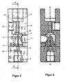
- FIG. 1 to 3 illustrated apparatus for preparing a mixture, in particular a foam-like cleaning mixture has a liquid inlet 4, a liquid channel 6 and a liquid nozzle 8.
- the liquid inlet 4 communicates with the liquid nozzle 8 by means of the liquid channel 6.
- the liquid channel 6 is formed as a taper 10 of the liquid inlet 4 is substantially concentric therewith.
- the liquid nozzle 8 ends as the end of the liquid channel 6 in a mixing space 12 in which a center inlet 14 ends perpendicular to the direction of the liquid nozzle 8.
- the device has a flow space 16, which is connected by means of a connecting channel 18 with the mixing chamber 12.
- a compressed gas nozzle 22 which is brought by means of a compressed gas inlet 20 with a pressurized gas, in particular with compressed air in combination.
- the compressed gas nozzle 22 is directed parallel to the connecting channel 18 in the flow space 16.
- the liquid channel 6 has a further, essentially concentric narrowing 26.
- the mixing chamber 12 is cylindrical and concentric with the liquid channel 6.
- the connection of the connecting channel 18 with the mixing chamber 12 has a concentric taper 28.
- the front part of the liquid nozzle 8 is formed as a bore of 1.8 with a length of 9 mm.
- the connecting channel 18 is formed as a bore of 3.5 mm.
- the distance between the liquid nozzle 8 and the connecting channel 18 is 5.82 mm in the present, advantageous and tested embodiment.
- another center inlet is formed. This is perpendicular to the connecting channel 18 and the compressed gas nozzle 22, ends in the flow space and can be acted upon by a further agent.
- the injector is made by welding of two parts, which in the following "female part” according to the FIGS. 4 to 6 and “male part” according to the FIGS. 7 to 9 to be named.
- female part according to the FIGS. 4 to 6
- male part according to the FIGS. 7 to 9 to be named.
Landscapes
- Chemical & Material Sciences (AREA)
- Chemical Kinetics & Catalysis (AREA)
- Cleaning By Liquid Or Steam (AREA)
- Nozzles (AREA)
Description
Die Erfindung betrifft einen Injektor, nämlich eine Vorrichtung zum Aufbereiten eines Gemisches, insbesondere eines schaumartigen Reinigungsgemisches.The invention relates to an injector, namely a device for processing a mixture, in particular a foam-like cleaning mixture.
Beim Erzeugen eines Reinigungsschaumes aus Wasser und einer chemischen Substanz mittels Druckluft oder Druckgas tritt das Problem auf, dass - ohne eine übermässige Erhöhung der Druckluft üblicherweise nur ca. 3% (bei Hochdruck) bzw. max. 8% (bei Niederdruck) der chemischen Substanz im Reinigungsschaum angereichert werden kann. Andererseits hat eine übermässige Erhöhung der Druckluft Flattereigenschaften und damit unterschiedliche Anreicherungswerte der chemischen Substanz zur Folge.When creating a cleaning foam of water and a chemical substance by means of compressed air or compressed gas, the problem arises that - without an excessive increase in compressed air usually only about 3% (at high pressure) or max. 8% (at low pressure) of the chemical substance in the cleaning foam can be enriched. On the other hand, an excessive increase in the compressed air has flutter characteristics and thus different enrichment values of the chemical substance.
Aus der
In der
Die Aufgabe der Erfindung ist es, eine Vorrichtung zum Aufbereiten eines Gemisches, insbesondere eines schaumartigen Reinigungsgemisches vorzuschlagen, die die Nachteile des genannten Standes der Technik überwinden soll.The object of the invention is to provide a device for preparing a mixture, in particular a foam-like cleaning mixture, which is intended to overcome the disadvantages of the cited prior art.
Die Aufgabe der Erfindung wird durch eine Vorrichtung zum Aufbereiten eines Gemisches nach Anspruch 1 gelöst. Dabei haben die Massnahmen der Erfindung zur Folge, dass mit der vorgeschlagenen Vorrichtung zum Aufbereiten eines Gemisches, insbesondere eines schaumartigen Reinigungsgemisches leicht Anreicherungswerte der chemischen Substanz von über 5%, bei der Wahl geeigneter Bedingungen auch bis über 30% ermöglicht werden.The object of the invention is achieved by a device for processing a mixture according to claim 1. The measures of the invention result in that with the proposed device for preparing a mixture, in particular a foam-like cleaning mixture easily enrichment values of the chemical substance of more than 5%, are made possible with the choice of suitable conditions to over 30%.
Bei der erfindungsgemässen Vorrichtung mit einem Flüssigkeitseinlass, einem Flüssigkeitskanal und einer Flüssigkeitsdüse, bei der der Flüssigkeitseinlass mittels des Flüssigkeitskanals mit der Flüssigkeitsdüse in Verbindung steht und bei der der Flüssigkeitskanal als Verjüngung des Flüssigkeitseinlasses im Wesentlichen konzentrisch mit diesem ausgebildet ist, einem Mischraum, in welchem die Flüssigkeitsdüse im Wesentlichen als Ende des Flüssigkeitskanals endet, einem Mitteleinlass, welcher im Wesentlichen senkrecht zur Richtung der Flüssigkeitsdüse im Mischraum endet, einem Strömungsraum, einem Verbindungskanal, welcher den Mischraum mit dem Strömungsraum verbindet und einem Druckgaseinlass, der mit Druckluft in Verbindung bringbar ist, und einer Druckgasdüse, die im Strömungsraum endet und welche mit der Druckluft des Druckgaseinlasses beaufschlagbar ist, scheint es erheblich konstruktive Vorteile zu haben, wenn die Druckgasdüse im Wesentlichen parallel zum Verbindungskanal im Strömungsraum gerichtet ist.In the device according to the invention with a liquid inlet, a liquid channel and a liquid nozzle in which the liquid inlet communicates with the liquid nozzle by means of the liquid channel and in which the liquid channel is formed as a taper of the liquid inlet substantially concentric therewith, a mixing space in which Liquid nozzle terminates substantially as the end of the liquid passage, a center inlet, which ends substantially perpendicular to the direction of the liquid nozzle in the mixing space, a flow space, a connecting channel which connects the mixing space with the flow space and a compressed gas inlet, which is in communication with compressed air, and a Druckgasdüse, which ends in the flow space and which can be acted upon by the compressed air of the compressed gas inlet, it seems to have considerable design advantages, if the compressed gas nozzle substantially parallel to verbi tion channel is directed in the flow space.
Vorteilhaft ist es, wenn die Vorrichtung einen weiteren Mitteleinlass aufweist, der im Wesentlichen senkrecht zum Verbindungskanal und zur Druckgasdüse im Strömungsraum endet und mit einem weiteren Mittel beaufschlagbar ist. Dann kann die Vorrichtung nämlich auch ohne eine Beaufschlagung des ersten Mitteleinlasses mit einer chemischen Substanz - oder zusätzlich dazu - betrieben werden, wenn die alternative oder zusätzliche Substanz nicht als Reinigungsschaum aufbereitet werden soll. Wenn man Luft dazu gibt, kann auch ein vordosierter Reinigungsschaum aufbereitet werden.It is advantageous if the device has a further central inlet, which ends substantially perpendicular to the connecting channel and the compressed gas nozzle in the flow space and can be acted upon by a further agent. In that case, the device can also be operated without, or in addition to, applying a chemical agent to the first central inlet, if the alternative or additional substance is not intended to be treated as a cleaning foam. If you give it air, a pre-dosed cleaning foam can be prepared.
Hinsichtlich der Herstellung ist es besonders vorteilhaft, wenn der Flüssigkeitskanal eine weitere, im Wesentlichen konzentrische Verjüngung aufweist, da dann die Bohrungen sukzessive gebohrt werden können.With regard to the production, it is particularly advantageous if the liquid channel has a further, substantially concentric taper, since then the holes can be drilled successively.
Erfindungsgemäss ist der Mischraum im Wesentlichen zylindrisch und konzentrisch zum Flüssigkeitskanal ausgebildet sein. Der Anschluss des Verbindungskanals mit dem Mischraum wird vorteilhafterweise eine im Wesentlichen konzentrische Verjüngung aufweisen.According to the invention, the mixing space is essentially cylindrical and concentric with the liquid channel. The connection of the connection channel with the mixing chamber will advantageously have a substantially concentric taper.
Wie schon bei dem Injektor der
In der genannten Auslegung erscheint es wichtig, wenn der Flüssigkeitskanal einen vorderen Teil - nämlich die eigentliche Flüssigkeitsdüse - aufweist, der als Bohrung von 1.0 bis 2.5 mm, für einen Wasserdruck von 100 bis 200 bar vorzugsweise von 1.2 bis 1.6 mm, für einen Wasserdruck von 15 bis 60 bar vorzugsweise 1.7 bis 2.1 mm und der Verbindungskanal als Bohrung von 3.0 bis 4.0 mm, vorzugsweise von ca. 3.5 mm ausgebildet ist.In the above design, it appears important if the liquid channel has a front part - namely the actual liquid nozzle - which as a bore of 1.0 to 2.5 mm, for a water pressure of 100 to 200 bar, preferably from 1.2 to 1.6 mm, for a water pressure of 15 to 60 bar preferably 1.7 to 2.1 mm and the connecting channel is designed as a bore of 3.0 to 4.0 mm, preferably of about 3.5 mm.
Der Flüssigkeitskanal sollte eine Länge von 12 bis 20 mm, vorzugsweise von ca. 15 mm und die Länge der dünnsten Bohrung 7 bis 11 mm, vorzugsweise von ca. 9 mm aufweisen.The liquid channel should have a length of 12 to 20 mm, preferably of about 15 mm and the length of the thinnest hole 7 to 11 mm, preferably of about 9 mm.
Die vorbenannten sowie die beanspruchten und in den nachfolgenden Ausführungsbeispielen beschriebenen, erfindungsgemäss zu verwendenden Elemente unterliegen in ihrer Grösse, Formgestaltung, Materialverwendung und ihrer technischen Konzeption keinen besonderen Ausnahmebedingungen, so dass die in dem jeweiligen Anwendungsgebiet bekannten Auswahlkriterien uneingeschränkt Anwendung finden können.The above-mentioned as well as the claimed and described in the following embodiments, according to the invention to be used elements are subject to their size, shape design, material usage and their technical conception no special conditions of exception, so that the well-known in the respective field of application selection criteria can apply without restriction.
Weitere Einzelheiten, Vorteile und Merkmale des Gegenstandes der vorliegenden Erfindung ergeben sich aus der nachfolgenden Beschreibung der dazu gehörenden Zeichnungen, in denen - beispielhaft - erfindungsgemässe Injektoren erläutert werden. In den Zeichnungen zeigt:
- Figur 1
- eine schematische 3-D Ansicht eines Injektors gemäss einem Ausführungsbeispiels der Erfindung, mit dem Strebenprofil und dem Verbindungssteg, in perspektivischer Darstellung;
Figur 2- eine Ansicht der funktionalen Elemente entsprechend
Figur 1 ; - Figur 3
- eine Ansicht gemäss
Figur 2 Figur 4- ein weiblicher Teil des Injektors gemäss den
Figuren 1 bis 3 ; - Figur 5
- der weibliche Teil gemäss
Figur 4 Figur 6- der weibliche Teil gemäss den
Figuren 4 und 5 - Figur 7
- ein männlicher Teil des Injektors gemäss den
Figuren 1 bis 3 ; Figur 8- der männliche Teil gemäss
Figur 7 entlang der Schnittlinie A-A; und - Figur 9
- der männliche Teil gemäss den
Figuren 7 und 8 in Ansicht auf den Eingang.
- FIG. 1
- a schematic 3-D view of an injector according to an embodiment of the invention, with the strut profile and the connecting web, in perspective view;
- FIG. 2
- a view of the functional elements accordingly
FIG. 1 ; - FIG. 3
- a view according to
FIG. 2 wherein the injector is shown rotated by 180 °; - FIG. 4
- a female part of the injector according to the
FIGS. 1 to 3 ; - FIG. 5
- the female part according to
FIG. 4 along the section line AA, rotated by 90 °; - FIG. 6
- the female part according to the
FIGS. 4 and 5 in bottom view; - FIG. 7
- a male part of the injector according to the
FIGS. 1 to 3 ; - FIG. 8
- the male part according to
FIG. 7 along the section line AA; and - FIG. 9
- the male part according to the
FIGS. 7 and 8 in view of the entrance.
Die in
Im Strömungsraum endet weiterhin eine Druckgasdüse 22, welche mittels eines Druckgaseinlasses 20 mit einem Druckgas, insbesondere mit Druckluft in Verbindung bringbar ist. Die Druckgasdüse 22 ist parallel zum Verbindungskanal 18 im Strömungsraum 16 gerichtet.In the flow space also ends a
Im vorliegenden Ausführungsbeispiel hat der Flüssigkeitskanal 6 eine weitere, im Wesentlichen konzentrische Verjüngung 26. Der Mischraum 12 ist zylindrisch und konzentrisch zum Flüssigkeitskanal 6 ausgebildet. Der Anschluss des Verbindungskanals 18 mit dem Mischraum 12 weist eine konzentrische Verjüngung 28 auf. Wie in den
In einem alternativen Ausführungsbeispiel ist ein weiterer Mitteleinlass ausgebildet. Dieser steht senkrecht zum Verbindungskanal 18 und zur Druckgasdüse 22, endet im Strömungsraum und ist mit einem weiteren Mittel beaufschlagbar.In an alternative embodiment, another center inlet is formed. This is perpendicular to the connecting
Im vorliegenden Ausführungsbeispiel ist der Injektor durch Verschweissen aus zwei Teilen hergestellt, die im folgenden "weiblicher Teil" gemäss den
- 22
- Vorrichtung zum Aufbereiten eines GemischesApparatus for preparing a mixture
- 44
- Flüssigkeitseinlassliquid inlet
- 66
- Flüssigkeitskanalliquid channel
- 88th
- Flüssigkeitsdüsefluid nozzle
- 1010
- Verjüngung des FlüssigkeitseinlassesRejuvenation of the fluid inlet
- 1212
- Mischraummixing room
- 1414
- Mitteleinlassinlet
- 1616
- Strömungsraumflow chamber
- 1818
- Verbindungskanalconnecting channel
- 2020
- DruckgaseinlassCompressed gas inlet
- 2222
- Druckgasdüsecompressed gas nozzle
- 2626
- weitere Verjüngungfurther rejuvenation
- 2828
- VerjüngugVerjüngug
Claims (9)
- An apparatus for preparing a foam-like cleaning mixture, comprising- a liquid inlet (4), a liquid channel (6) and a liquid nozzle (8), wherein the liquid inlet (4) is in communication with the liquid nozzle (8) by means of the liquid channel (6) and wherein the liquid channel (6) is configured as a tapered region (10) of the liquid inlet (4) in a substantially concentric manner,- a mixing chamber (12) into which the liquid nozzle (8) ends by substantially forming an end of the liquid channel (6),- a media inlet (14) that ends into the mixing chamber (12) substantially perpendicularly to the direction of the liquid nozzle (8),- a flow chamber (16),- a connecting channel (18) that connects the mixing chamber (12) with the flow chamber (16) and- a pressurized gas inlet (20) that can be brought into communication with a pressurized gas, in particular with pressurized air, and a pressurized gas nozzle (22) that ends into the flow chamber (16) and that can be loaded with the pressurized gas from the pressurized gas inlet (20), the pressurized gas nozzle (22) being aligned substantially parallel to the connecting channel (18) in the flow chamber (16),characterized in that
the mixing chamber (12) is configured substantially cylindrical and concentric to the liquid channel (6),
with the liquid nozzle (8) protruding by over 50% into the mixing chamber (12) all the way to behind the mixing inlet (14),
the liquid nozzle (8) comprises a front part that is configured as a borehole of 1.0 to 2.5 mm,
the connecting channel (18) is configured as a borehole of 3.0 to 4.0 mm, the distance between the liquid nozzle (8) and the connecting channel (18) is 4.0 to 8.0 mm
and wherein the liquid channel (6) has a length of 12 to 20 mm, and the length of the thinnest borehole is 7 to 11 mm. - The apparatus according to claim 1, characterized by a further media inlet, that ends into the flow chamber (16) substantially perpendicularly to the connecting channel (18) and to the pressurized gas nozzle (22) and that can be loaded with a further medium.
- The apparatus according to claim 1 or 2, characterized in that the liquid channel (6) comprises one further, substantially concentric tapered region (26).
- The apparatus according to one of the preceding claims, characterized in that the connection of the connecting channel (18) has a tapered region substantially concentric with the mixing chamber (12).
- The apparatus according to one of the preceding claims, characterized in that the liquid nozzle (8) protrudes by about 70% into the mixing chamber (12).
- The apparatus according to one of the preceding claims, characterized in that the liquid nozzle (8) comprises a front part that is configured as a borehole of 1.2 to 1.6 mm for a water pressure of 100 to 200 bar, 1.7 to 2.1 for a water pressure of 15 to 60 bar.
- The apparatus according to one of the preceding claims, characterized in that the connecting channel (18) is configured as a borehole of about 3.5 mm.
- The apparatus according to one of the preceding claims, characterized in that the distance between the liquid nozzle (8) and the connecting channel (18) is 5.5 to 6.5 mm.
- The apparatus according to one of the preceding claims, characterized in that the liquid channel (6) has a length of about 15 mm, and the length of the thinnest borehole is about 9 mm.
Priority Applications (1)
| Application Number | Priority Date | Filing Date | Title |
|---|---|---|---|
| EP11174645.9A EP2548633B1 (en) | 2011-07-20 | 2011-07-20 | Injector |
Applications Claiming Priority (1)
| Application Number | Priority Date | Filing Date | Title |
|---|---|---|---|
| EP11174645.9A EP2548633B1 (en) | 2011-07-20 | 2011-07-20 | Injector |
Publications (2)
| Publication Number | Publication Date |
|---|---|
| EP2548633A1 EP2548633A1 (en) | 2013-01-23 |
| EP2548633B1 true EP2548633B1 (en) | 2014-05-07 |
Family
ID=45065556
Family Applications (1)
| Application Number | Title | Priority Date | Filing Date |
|---|---|---|---|
| EP11174645.9A Active EP2548633B1 (en) | 2011-07-20 | 2011-07-20 | Injector |
Country Status (1)
| Country | Link |
|---|---|
| EP (1) | EP2548633B1 (en) |
Family Cites Families (4)
| Publication number | Priority date | Publication date | Assignee | Title |
|---|---|---|---|---|
| US3547409A (en) * | 1968-05-23 | 1970-12-15 | Jacuzzi Bros Inc | Assembly for producing detergent foam |
| DE3005653A1 (en) * | 1980-02-15 | 1981-08-20 | Brown, Boveri & Cie Ag, 6800 Mannheim | Steam-driven feed water injector - has mixing chamber with auxiliary and main diffusors and secondary diffusor to remove excess water |
| US4505431A (en) * | 1982-06-14 | 1985-03-19 | Spraco, Inc. | Apparatus for discharging three commingled fluids _ |
| DE10342000A1 (en) | 2003-09-08 | 2005-04-07 | Alfred Kärcher Gmbh & Co. Kg | Method for producing a detergent foam and foam generation system for carrying out the method |
-
2011
- 2011-07-20 EP EP11174645.9A patent/EP2548633B1/en active Active
Also Published As
| Publication number | Publication date |
|---|---|
| EP2548633A1 (en) | 2013-01-23 |
Similar Documents
| Publication | Publication Date | Title |
|---|---|---|
| DE202013002283U1 (en) | Sprayer nozzle for a sanitary water spout and sanitary outlet fitting with a water outlet | |
| EP2540400A1 (en) | Full ball nozzle | |
| DE102015105047A1 (en) | Reduction sleeve with coolant flow and a cutting device that uses such a reducer | |
| DE102006053625A1 (en) | Rotor nozzle for high pressure cleaning device, has switching ball releasing outlet opening and locking functional opening in operating mode, where outlet opening is locked and functional opening is released in another operating mode | |
| DE1600470A1 (en) | Interchangeable and convertible multipurpose connection system for pipelines | |
| DE102011077995B4 (en) | Mixing device for a dental powder blasting device and a dental hand instrument for a powder blasting device with a corresponding mixing device | |
| DE102009060151A1 (en) | Butt joint between ends of sealing strands or a sealing strand | |
| EP2548633B1 (en) | Injector | |
| EP2749335A1 (en) | Two-part particle filter and method for producing the same | |
| WO1991012930A1 (en) | Device for cutting and cleaning objects using a water/abrasive mixture at high pressure | |
| DE2261674A1 (en) | DEVICE FOR SUCTIONING AND ADDING ADDITIVES INTO A FLOW OF LIQUID | |
| DE69400060T2 (en) | Flat jet nozzle, especially for high pressure cleaners | |
| DE202013011901U1 (en) | Hydrokavitationsgenerator | |
| WO2014030055A1 (en) | Housing for a radial fan with a pressure measurement channel integrated in the fan inlet | |
| DE102005003661B4 (en) | Venturi mixing nozzle | |
| DE202021101830U1 (en) | Nozzle head and nozzle | |
| DE202015001520U1 (en) | full cone nozzle | |
| DE102006018066A1 (en) | Pneumatically operated injector`s driving nozzle for feeding coating powder, has upstream channel section arranged between discharge air inlet and another upstream channel section, where outer contour of nozzle tapers for air outlet | |
| EP1733785B1 (en) | Apparatus and set for mixing a granular solid material or a liquid with a liquid | |
| DE2742018A1 (en) | Two component plastics foam mixing head - has conical insert in chamber with component mixing cylinder in injection nozzle of spray gun | |
| DE10321432B4 (en) | water jet | |
| DE202008010700U1 (en) | Connecting and / or connecting body device for attachment to a connection part of a working channel of an endoscope | |
| WO2010009887A1 (en) | Device for filling air tires with a tire sealing fluid | |
| DE112018000277B4 (en) | Flow control valve, fuel supply assembly and vehicle | |
| DE102005046619B4 (en) | Hydraulic block for a hydraulic vehicle brake system with slip control |
Legal Events
| Date | Code | Title | Description |
|---|---|---|---|
| PUAI | Public reference made under article 153(3) epc to a published international application that has entered the european phase |
Free format text: ORIGINAL CODE: 0009012 |
|
| AK | Designated contracting states |
Kind code of ref document: A1 Designated state(s): AL AT BE BG CH CY CZ DE DK EE ES FI FR GB GR HR HU IE IS IT LI LT LU LV MC MK MT NL NO PL PT RO RS SE SI SK SM TR |
|
| AX | Request for extension of the european patent |
Extension state: BA ME |
|
| 17P | Request for examination filed |
Effective date: 20130702 |
|
| RBV | Designated contracting states (corrected) |
Designated state(s): AL AT BE BG CH CY CZ DE DK EE ES FI FR GB GR HR HU IE IS IT LI LT LU LV MC MK MT NL NO PL PT RO RS SE SI SK SM TR |
|
| RIC1 | Information provided on ipc code assigned before grant |
Ipc: B01F 5/04 20060101ALI20131210BHEP Ipc: B01F 3/04 20060101AFI20131210BHEP Ipc: B08B 3/02 20060101ALN20131210BHEP |
|
| GRAP | Despatch of communication of intention to grant a patent |
Free format text: ORIGINAL CODE: EPIDOSNIGR1 |
|
| INTG | Intention to grant announced |
Effective date: 20140120 |
|
| GRAS | Grant fee paid |
Free format text: ORIGINAL CODE: EPIDOSNIGR3 |
|
| GRAA | (expected) grant |
Free format text: ORIGINAL CODE: 0009210 |
|
| AK | Designated contracting states |
Kind code of ref document: B1 Designated state(s): AL AT BE BG CH CY CZ DE DK EE ES FI FR GB GR HR HU IE IS IT LI LT LU LV MC MK MT NL NO PL PT RO RS SE SI SK SM TR |
|
| REG | Reference to a national code |
Ref country code: GB Ref legal event code: FG4D Free format text: NOT ENGLISH |
|
| REG | Reference to a national code |
Ref country code: AT Ref legal event code: REF Ref document number: 666151 Country of ref document: AT Kind code of ref document: T Effective date: 20140515 |
|
| REG | Reference to a national code |
Ref country code: IE Ref legal event code: FG4D Free format text: LANGUAGE OF EP DOCUMENT: GERMAN |
|
| REG | Reference to a national code |
Ref country code: DE Ref legal event code: R096 Ref document number: 502011002988 Country of ref document: DE Effective date: 20140612 |
|
| REG | Reference to a national code |
Ref country code: CH Ref legal event code: NV Representative=s name: SCHMAUDER AND PARTNER AG PATENT- UND MARKENANW, CH |
|
| REG | Reference to a national code |
Ref country code: NL Ref legal event code: VDEP Effective date: 20140507 |
|
| REG | Reference to a national code |
Ref country code: LT Ref legal event code: MG4D |
|
| PG25 | Lapsed in a contracting state [announced via postgrant information from national office to epo] |
Ref country code: IS Free format text: LAPSE BECAUSE OF FAILURE TO SUBMIT A TRANSLATION OF THE DESCRIPTION OR TO PAY THE FEE WITHIN THE PRESCRIBED TIME-LIMIT Effective date: 20140907 Ref country code: LT Free format text: LAPSE BECAUSE OF FAILURE TO SUBMIT A TRANSLATION OF THE DESCRIPTION OR TO PAY THE FEE WITHIN THE PRESCRIBED TIME-LIMIT Effective date: 20140507 Ref country code: GR Free format text: LAPSE BECAUSE OF FAILURE TO SUBMIT A TRANSLATION OF THE DESCRIPTION OR TO PAY THE FEE WITHIN THE PRESCRIBED TIME-LIMIT Effective date: 20140808 Ref country code: NO Free format text: LAPSE BECAUSE OF FAILURE TO SUBMIT A TRANSLATION OF THE DESCRIPTION OR TO PAY THE FEE WITHIN THE PRESCRIBED TIME-LIMIT Effective date: 20140807 Ref country code: FI Free format text: LAPSE BECAUSE OF FAILURE TO SUBMIT A TRANSLATION OF THE DESCRIPTION OR TO PAY THE FEE WITHIN THE PRESCRIBED TIME-LIMIT Effective date: 20140507 Ref country code: CY Free format text: LAPSE BECAUSE OF FAILURE TO SUBMIT A TRANSLATION OF THE DESCRIPTION OR TO PAY THE FEE WITHIN THE PRESCRIBED TIME-LIMIT Effective date: 20140507 |
|
| PG25 | Lapsed in a contracting state [announced via postgrant information from national office to epo] |
Ref country code: PL Free format text: LAPSE BECAUSE OF FAILURE TO SUBMIT A TRANSLATION OF THE DESCRIPTION OR TO PAY THE FEE WITHIN THE PRESCRIBED TIME-LIMIT Effective date: 20140507 Ref country code: ES Free format text: LAPSE BECAUSE OF FAILURE TO SUBMIT A TRANSLATION OF THE DESCRIPTION OR TO PAY THE FEE WITHIN THE PRESCRIBED TIME-LIMIT Effective date: 20140507 Ref country code: RS Free format text: LAPSE BECAUSE OF FAILURE TO SUBMIT A TRANSLATION OF THE DESCRIPTION OR TO PAY THE FEE WITHIN THE PRESCRIBED TIME-LIMIT Effective date: 20140507 Ref country code: LV Free format text: LAPSE BECAUSE OF FAILURE TO SUBMIT A TRANSLATION OF THE DESCRIPTION OR TO PAY THE FEE WITHIN THE PRESCRIBED TIME-LIMIT Effective date: 20140507 Ref country code: SE Free format text: LAPSE BECAUSE OF FAILURE TO SUBMIT A TRANSLATION OF THE DESCRIPTION OR TO PAY THE FEE WITHIN THE PRESCRIBED TIME-LIMIT Effective date: 20140507 Ref country code: HR Free format text: LAPSE BECAUSE OF FAILURE TO SUBMIT A TRANSLATION OF THE DESCRIPTION OR TO PAY THE FEE WITHIN THE PRESCRIBED TIME-LIMIT Effective date: 20140507 |
|
| PG25 | Lapsed in a contracting state [announced via postgrant information from national office to epo] |
Ref country code: PT Free format text: LAPSE BECAUSE OF FAILURE TO SUBMIT A TRANSLATION OF THE DESCRIPTION OR TO PAY THE FEE WITHIN THE PRESCRIBED TIME-LIMIT Effective date: 20140908 |
|
| PG25 | Lapsed in a contracting state [announced via postgrant information from national office to epo] |
Ref country code: EE Free format text: LAPSE BECAUSE OF FAILURE TO SUBMIT A TRANSLATION OF THE DESCRIPTION OR TO PAY THE FEE WITHIN THE PRESCRIBED TIME-LIMIT Effective date: 20140507 Ref country code: SK Free format text: LAPSE BECAUSE OF FAILURE TO SUBMIT A TRANSLATION OF THE DESCRIPTION OR TO PAY THE FEE WITHIN THE PRESCRIBED TIME-LIMIT Effective date: 20140507 Ref country code: DK Free format text: LAPSE BECAUSE OF FAILURE TO SUBMIT A TRANSLATION OF THE DESCRIPTION OR TO PAY THE FEE WITHIN THE PRESCRIBED TIME-LIMIT Effective date: 20140507 Ref country code: CZ Free format text: LAPSE BECAUSE OF FAILURE TO SUBMIT A TRANSLATION OF THE DESCRIPTION OR TO PAY THE FEE WITHIN THE PRESCRIBED TIME-LIMIT Effective date: 20140507 Ref country code: RO Free format text: LAPSE BECAUSE OF FAILURE TO SUBMIT A TRANSLATION OF THE DESCRIPTION OR TO PAY THE FEE WITHIN THE PRESCRIBED TIME-LIMIT Effective date: 20140507 |
|
| REG | Reference to a national code |
Ref country code: DE Ref legal event code: R097 Ref document number: 502011002988 Country of ref document: DE |
|
| PG25 | Lapsed in a contracting state [announced via postgrant information from national office to epo] |
Ref country code: LU Free format text: LAPSE BECAUSE OF FAILURE TO SUBMIT A TRANSLATION OF THE DESCRIPTION OR TO PAY THE FEE WITHIN THE PRESCRIBED TIME-LIMIT Effective date: 20140720 Ref country code: NL Free format text: LAPSE BECAUSE OF FAILURE TO SUBMIT A TRANSLATION OF THE DESCRIPTION OR TO PAY THE FEE WITHIN THE PRESCRIBED TIME-LIMIT Effective date: 20140507 |
|
| PLBE | No opposition filed within time limit |
Free format text: ORIGINAL CODE: 0009261 |
|
| STAA | Information on the status of an ep patent application or granted ep patent |
Free format text: STATUS: NO OPPOSITION FILED WITHIN TIME LIMIT |
|
| 26N | No opposition filed |
Effective date: 20150210 |
|
| REG | Reference to a national code |
Ref country code: IE Ref legal event code: MM4A |
|
| PG25 | Lapsed in a contracting state [announced via postgrant information from national office to epo] |
Ref country code: IT Free format text: LAPSE BECAUSE OF FAILURE TO SUBMIT A TRANSLATION OF THE DESCRIPTION OR TO PAY THE FEE WITHIN THE PRESCRIBED TIME-LIMIT Effective date: 20140507 |
|
| REG | Reference to a national code |
Ref country code: DE Ref legal event code: R097 Ref document number: 502011002988 Country of ref document: DE Effective date: 20150210 |
|
| PG25 | Lapsed in a contracting state [announced via postgrant information from national office to epo] |
Ref country code: SI Free format text: LAPSE BECAUSE OF FAILURE TO SUBMIT A TRANSLATION OF THE DESCRIPTION OR TO PAY THE FEE WITHIN THE PRESCRIBED TIME-LIMIT Effective date: 20140507 |
|
| PG25 | Lapsed in a contracting state [announced via postgrant information from national office to epo] |
Ref country code: IE Free format text: LAPSE BECAUSE OF NON-PAYMENT OF DUE FEES Effective date: 20140720 |
|
| PG25 | Lapsed in a contracting state [announced via postgrant information from national office to epo] |
Ref country code: SM Free format text: LAPSE BECAUSE OF FAILURE TO SUBMIT A TRANSLATION OF THE DESCRIPTION OR TO PAY THE FEE WITHIN THE PRESCRIBED TIME-LIMIT Effective date: 20140507 Ref country code: MC Free format text: LAPSE BECAUSE OF FAILURE TO SUBMIT A TRANSLATION OF THE DESCRIPTION OR TO PAY THE FEE WITHIN THE PRESCRIBED TIME-LIMIT Effective date: 20140507 |
|
| PG25 | Lapsed in a contracting state [announced via postgrant information from national office to epo] |
Ref country code: MT Free format text: LAPSE BECAUSE OF FAILURE TO SUBMIT A TRANSLATION OF THE DESCRIPTION OR TO PAY THE FEE WITHIN THE PRESCRIBED TIME-LIMIT Effective date: 20140507 Ref country code: BG Free format text: LAPSE BECAUSE OF FAILURE TO SUBMIT A TRANSLATION OF THE DESCRIPTION OR TO PAY THE FEE WITHIN THE PRESCRIBED TIME-LIMIT Effective date: 20140507 |
|
| PG25 | Lapsed in a contracting state [announced via postgrant information from national office to epo] |
Ref country code: HU Free format text: LAPSE BECAUSE OF FAILURE TO SUBMIT A TRANSLATION OF THE DESCRIPTION OR TO PAY THE FEE WITHIN THE PRESCRIBED TIME-LIMIT; INVALID AB INITIO Effective date: 20110720 Ref country code: BE Free format text: LAPSE BECAUSE OF FAILURE TO SUBMIT A TRANSLATION OF THE DESCRIPTION OR TO PAY THE FEE WITHIN THE PRESCRIBED TIME-LIMIT Effective date: 20140731 Ref country code: TR Free format text: LAPSE BECAUSE OF FAILURE TO SUBMIT A TRANSLATION OF THE DESCRIPTION OR TO PAY THE FEE WITHIN THE PRESCRIBED TIME-LIMIT Effective date: 20140507 |
|
| REG | Reference to a national code |
Ref country code: FR Ref legal event code: PLFP Year of fee payment: 6 |
|
| REG | Reference to a national code |
Ref country code: FR Ref legal event code: PLFP Year of fee payment: 7 |
|
| PG25 | Lapsed in a contracting state [announced via postgrant information from national office to epo] |
Ref country code: MK Free format text: LAPSE BECAUSE OF FAILURE TO SUBMIT A TRANSLATION OF THE DESCRIPTION OR TO PAY THE FEE WITHIN THE PRESCRIBED TIME-LIMIT Effective date: 20140507 |
|
| REG | Reference to a national code |
Ref country code: FR Ref legal event code: PLFP Year of fee payment: 8 |
|
| PG25 | Lapsed in a contracting state [announced via postgrant information from national office to epo] |
Ref country code: AL Free format text: LAPSE BECAUSE OF FAILURE TO SUBMIT A TRANSLATION OF THE DESCRIPTION OR TO PAY THE FEE WITHIN THE PRESCRIBED TIME-LIMIT Effective date: 20140507 |
|
| PGFP | Annual fee paid to national office [announced via postgrant information from national office to epo] |
Ref country code: FR Payment date: 20210729 Year of fee payment: 11 |
|
| REG | Reference to a national code |
Ref country code: DE Ref legal event code: R079 Ref document number: 502011002988 Country of ref document: DE Free format text: PREVIOUS MAIN CLASS: B01F0003040000 Ipc: B01F0023200000 |
|
| PGFP | Annual fee paid to national office [announced via postgrant information from national office to epo] |
Ref country code: GB Payment date: 20210722 Year of fee payment: 11 |
|
| GBPC | Gb: european patent ceased through non-payment of renewal fee |
Effective date: 20220720 |
|
| PG25 | Lapsed in a contracting state [announced via postgrant information from national office to epo] |
Ref country code: FR Free format text: LAPSE BECAUSE OF NON-PAYMENT OF DUE FEES Effective date: 20220731 |
|
| PG25 | Lapsed in a contracting state [announced via postgrant information from national office to epo] |
Ref country code: GB Free format text: LAPSE BECAUSE OF NON-PAYMENT OF DUE FEES Effective date: 20220720 |
|
| PGFP | Annual fee paid to national office [announced via postgrant information from national office to epo] |
Ref country code: CH Payment date: 20230801 Year of fee payment: 13 Ref country code: AT Payment date: 20230720 Year of fee payment: 13 |
|
| PGFP | Annual fee paid to national office [announced via postgrant information from national office to epo] |
Ref country code: DE Payment date: 20240719 Year of fee payment: 14 |
|
| PGFP | Annual fee paid to national office [announced via postgrant information from national office to epo] |
Ref country code: CH Payment date: 20240801 Year of fee payment: 14 |
|
| PGFP | Annual fee paid to national office [announced via postgrant information from national office to epo] |
Ref country code: AT Payment date: 20240722 Year of fee payment: 14 |