EP2548529A1 - Medical manipulator - Google Patents
Medical manipulator Download PDFInfo
- Publication number
- EP2548529A1 EP2548529A1 EP11756113A EP11756113A EP2548529A1 EP 2548529 A1 EP2548529 A1 EP 2548529A1 EP 11756113 A EP11756113 A EP 11756113A EP 11756113 A EP11756113 A EP 11756113A EP 2548529 A1 EP2548529 A1 EP 2548529A1
- Authority
- EP
- European Patent Office
- Prior art keywords
- unit
- trigger lever
- operating unit
- input unit
- shaft
- Prior art date
- Legal status (The legal status is an assumption and is not a legal conclusion. Google has not performed a legal analysis and makes no representation as to the accuracy of the status listed.)
- Granted
Links
Images








Classifications
-
- A—HUMAN NECESSITIES
- A61—MEDICAL OR VETERINARY SCIENCE; HYGIENE
- A61B—DIAGNOSIS; SURGERY; IDENTIFICATION
- A61B17/00—Surgical instruments, devices or methods
- A61B17/28—Surgical forceps
- A61B17/29—Forceps for use in minimally invasive surgery
-
- A—HUMAN NECESSITIES
- A61—MEDICAL OR VETERINARY SCIENCE; HYGIENE
- A61B—DIAGNOSIS; SURGERY; IDENTIFICATION
- A61B34/00—Computer-aided surgery; Manipulators or robots specially adapted for use in surgery
- A61B34/30—Surgical robots
-
- A—HUMAN NECESSITIES
- A61—MEDICAL OR VETERINARY SCIENCE; HYGIENE
- A61B—DIAGNOSIS; SURGERY; IDENTIFICATION
- A61B34/00—Computer-aided surgery; Manipulators or robots specially adapted for use in surgery
- A61B34/30—Surgical robots
- A61B34/37—Leader-follower robots
-
- A—HUMAN NECESSITIES
- A61—MEDICAL OR VETERINARY SCIENCE; HYGIENE
- A61B—DIAGNOSIS; SURGERY; IDENTIFICATION
- A61B34/00—Computer-aided surgery; Manipulators or robots specially adapted for use in surgery
- A61B34/70—Manipulators specially adapted for use in surgery
- A61B34/71—Manipulators operated by drive cable mechanisms
-
- A—HUMAN NECESSITIES
- A61—MEDICAL OR VETERINARY SCIENCE; HYGIENE
- A61B—DIAGNOSIS; SURGERY; IDENTIFICATION
- A61B17/00—Surgical instruments, devices or methods
- A61B2017/00367—Details of actuation of instruments, e.g. relations between pushing buttons, or the like, and activation of the tool, working tip, or the like
- A61B2017/00398—Details of actuation of instruments, e.g. relations between pushing buttons, or the like, and activation of the tool, working tip, or the like using powered actuators, e.g. stepper motors, solenoids
-
- A—HUMAN NECESSITIES
- A61—MEDICAL OR VETERINARY SCIENCE; HYGIENE
- A61B—DIAGNOSIS; SURGERY; IDENTIFICATION
- A61B17/00—Surgical instruments, devices or methods
- A61B2017/0046—Surgical instruments, devices or methods with a releasable handle; with handle and operating part separable
-
- A—HUMAN NECESSITIES
- A61—MEDICAL OR VETERINARY SCIENCE; HYGIENE
- A61B—DIAGNOSIS; SURGERY; IDENTIFICATION
- A61B17/00—Surgical instruments, devices or methods
- A61B17/28—Surgical forceps
- A61B17/29—Forceps for use in minimally invasive surgery
- A61B17/2909—Handles
- A61B2017/2912—Handles transmission of forces to actuating rod or piston
- A61B2017/2919—Handles transmission of forces to actuating rod or piston details of linkages or pivot points
-
- A—HUMAN NECESSITIES
- A61—MEDICAL OR VETERINARY SCIENCE; HYGIENE
- A61B—DIAGNOSIS; SURGERY; IDENTIFICATION
- A61B17/00—Surgical instruments, devices or methods
- A61B17/28—Surgical forceps
- A61B17/29—Forceps for use in minimally invasive surgery
- A61B17/2909—Handles
- A61B2017/2912—Handles transmission of forces to actuating rod or piston
- A61B2017/2923—Toothed members, e.g. rack and pinion
-
- A—HUMAN NECESSITIES
- A61—MEDICAL OR VETERINARY SCIENCE; HYGIENE
- A61B—DIAGNOSIS; SURGERY; IDENTIFICATION
- A61B17/00—Surgical instruments, devices or methods
- A61B17/28—Surgical forceps
- A61B17/29—Forceps for use in minimally invasive surgery
- A61B17/2909—Handles
- A61B2017/2925—Pistol grips
-
- A—HUMAN NECESSITIES
- A61—MEDICAL OR VETERINARY SCIENCE; HYGIENE
- A61B—DIAGNOSIS; SURGERY; IDENTIFICATION
- A61B17/00—Surgical instruments, devices or methods
- A61B17/28—Surgical forceps
- A61B17/29—Forceps for use in minimally invasive surgery
- A61B2017/2926—Details of heads or jaws
- A61B2017/2932—Transmission of forces to jaw members
- A61B2017/2939—Details of linkages or pivot points
-
- A—HUMAN NECESSITIES
- A61—MEDICAL OR VETERINARY SCIENCE; HYGIENE
- A61B—DIAGNOSIS; SURGERY; IDENTIFICATION
- A61B34/00—Computer-aided surgery; Manipulators or robots specially adapted for use in surgery
- A61B34/70—Manipulators specially adapted for use in surgery
- A61B34/74—Manipulators with manual electric input means
- A61B2034/742—Joysticks
Definitions
- the present invention relates to a medical manipulator that includes an input unit which is operated by hands and a tip operating unit having an end effector operated based on the operation of the input unit.
- laparoscopic surgery In endoscopic surgery (or also referred to as "laparoscopic surgery"), a plurality of holes are drilled in an abdomen or the like of a patient, after a trocar (cylindrical instrument) is inserted into the holes, a laparoscope (camera) and a plurality of forceps are inserted into a body cavity through each trocar. Grippers, scissors, blades of an electrosurgical knife, and the like for gripping biological tissues are mounted on the tips of the forceps as an end effector. If the laparoscope and the forceps are inserted into the body cavity, an operator operates the forceps while viewing a state of the inner portion of the abdominal cavity that is reflected at the monitor connected to the laparoscope, and performs the surgery. Since the surgical procedure does not require a laparotomy, a burden on a patient is decreased, and a number of days until postoperative recovery or leaving hospital is significantly decreased. Thereby, expansion of the applied field of the surgical procedure has been expected.
- the medical manipulator As the forceps that are inserted from the trocar, in addition to general forceps that do not have a joint at the tip, forceps that have a plurality of joints at the tip and change a posture of the tip, that is, a so-called medical manipulator has been developed (for example, refer to JP-A-2004-105451 ). According to the medical manipulator, an operation having a high degree of freedom can be performed in the body cavity, manipulation is easier, and applicable cases are increased.
- the medical manipulator that is disclosed in JP-A-2004-105451 includes a working unit that includes a tip operating unit having an end effector and a joint and an operating unit having a drive mechanism for driving the tip operating unit.
- the drive mechanism includes an actuator for changing the posture of the tip operating unit and an actuator for opening and closing the end effector and drives each of the actuators according to the operation with respect to an operation input unit that is provided in the operating unit, and the tip operation unit is operated.
- a medical manipulator capable of allowing the gripping force that acts on the tip operating unit to be directly perceived.
- a configuration of the medical manipulator a configuration in which an operation to an input unit (for example, trigger lever) through hands is performed by being mechanically transmitted via a transmitting member such as a wire in the opening and closing operation of the end effector provided in the tip operating unit while the posture change of the tip operating unit is performed by the driving of the actuator, that is, a hybrid type configuration in which an electric drive and a manual drive are combined is considered.
- the present invention is made in consideration of the above-described circumstance, and an object thereof is to provide a medical manipulator capable of detecting an operation frequency or the use state of an end effector and a drive mechanism in the medical manipulator that includes the end effector in which an operation of an input unit is mechanically transmitted and is performed.
- a medical manipulator includes: a first input unit that is operated by hands; a shaft that extends from a body in which the first input unit is provided; a tip operating unit that is provided at a tip of the shaft and includes an end effector to which an operation of the first input unit is mechanically transmitted and in which the operation is performed; and a detection mechanism that detects an operation state of the first input unit.
- the operation state of the first input unit is detected by the detection mechanism, for example, ascertainment and analysis of an operation frequency or a use state of the first input unit can be performed based on the operation state, and according to the analysis, life span prediction and the like of the mechanism that mechanically transmits a force based on the first input unit or the operation of the first input unit can be performed.
- the detection mechanism detects that the first input unit reaches a predetermined position.
- the frequency of use of the first input unit can be ascertained based on the detection result.
- the detection mechanism detects that the first input unit reaches a predetermined position at each of a plurality of predetermined positions in a movable range of the first input unit.
- the detection mechanism detects a position in an operation direction of the first input unit.
- the operation frequency of the first input unit can be ascertained, the use state can be ascertained in detail, and the reliability of the life span prediction or the like is improved.
- the tip operating unit includes a posture change mechanism that changes a posture of the end effector with respect to the shaft; the medical manipulator further includes, an operating unit that includes a second input unit that is operated by hands, a grip handle that is gripped by hands, and a drive source that drives the posture change mechanism based on an operation of the second input unit, and a working unit that includes the tip operating unit, the shaft, and the first input unit and can be attached to and detached from the operating unit; a driving force of the drive source is mechanically transmitted to the posture change mechanism in a state where the working unit is mounted on the operating unit, thereby, a posture of the end effector is changed; the detection mechanism includes a protrusion piece for detection that is provided in the first input unit and a detecting unit that is provided in the operating unit; and the detecting unit detects the protrusion piece for detection in the state where the working unit is mounted on the operating unit, and thereby, detects that the first input unit reaches the predetermined position.
- the working unit since electronic equipment for operating the tip operation unit need not be provided in the working unit, and electronic equipment for detecting the operation state of the first input unit need not be provided in the working unit, the working unit can be easily cleaned and sterilized.
- the tip operating unit includes a posture change mechanism that changes a posture of the end effector with respect to the shaft; the medical manipulator further includes, an operating unit that includes a second input unit that is operated by hands, a grip handle that is gripped by hands, and a drive source that drives the posture change mechanism based on an operation of the second input unit, and a working unit that includes the tip operating unit, the shaft, and the first input unit and can be attached to and detached from the operating unit; a driving force of the drive source is mechanically transmitted to the posture change mechanism in the state where the working unit is mounted on the operating unit, thereby, a posture of the end effector is changed; and the detection mechanism includes, a drive element that is operated along with the first input unit, a driven element that is provided in the operating unit and operates in conjunction with the drive element in a state where the working unit is mounted on the operating unit, and a detecting unit that detects a position of an operation direction of the driven element.
- the working unit since the electronic equipment for operating the tip operation unit need not be provided in the working unit, and the electronic equipment for detecting the operation state of the first input unit need not be provided in the working unit, the working unit can be easily cleaned and sterilized.
- the first input unit is a trigger lever that is operated to rotate;
- the drive element is a first gear portion that includes teeth which extend in a circumferential direction around a rotation axial center of the trigger lever;
- the driven element is a second gear portion that is rotatably provided in the operating unit and meshes with the first gear portion in the state where the working unit is mounted on the operating unit;
- the detecting unit is a rotation detector that detects a rotation angle of the second gear portion.
- the operation angle of the trigger lever can be detected by a simple configuration.
- a rotation axial center of the trigger lever and a rotation axial center of the second gear portion are positioned so as to be off-set from each other in an extension direction of the shaft in the state where the working unit is mounted on the operating unit.
- the tip operating unit includes a conversion mechanism that converts an operation based on the operation of the first input unit to an operation of the end effector;
- the posture change mechanism includes a main shaft member in which a first rotation body that is rotated by a first actuator via a first transmitting member inserted into the shaft is provided and which can rotate about a tilt shaft which is non-parallel to an axial line of the shaft, a second rotation body that is rotated by a second actuator via a second transmitting member inserted into the shaft, and a third rotation body that is driven by the second rotation body and is supported to the main shaft member so as to rotate about the roll axis in an extension direction of the end effector;
- the main shaft member driven by the first transmitting member rotates about the tilt shaft, thereby, a tilting operation of the end effector is performed;
- the second rotation body driven by the second transmitting member rotates the third rotation body about the roll axis, thereby, a roll operation of the end effector is performed;
- the medical manipulator further includes
- the first actuator is controlled in addition to the operation state of the first input unit, even when the rotation resistance of the third rotation body is increased due to the operation state of the first input unit, the generation of the tilting operation due to the roll operation can be prevented or suppressed. Thereby, trajectory accuracy or positioning accuracy of the tip operating unit at the time of the roll operation can be improved.
- the end effector is configured of an opening and closing mechanism; and when the controller performs the control for the roll operation, in a case where the first input unit is positioned at the end of the movable range or the vicinity thereof, a compensation control corresponding to the increase of the rotation resistance of the third rotation body is performed with respect to the first actuator so as to prevent or suppress the generation of the tilting operation.
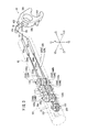
- the manipulator 10 is a medical instrument that grips a portion of a living body or contacts the living body through a tip operating unit 12 provided at a tip of the manipulator and performs a predetermined processing, and in general, is also referred to as gripping forceps, a needle drive (needle holder), or the like.
- the manipulator 10 includes a manipulator main body 11 that configures a medical instrument and a controller 29 that is connected to the manipulator main body 11 via a cable 28.
- the manipulator main body 11 includes a body 21, a shaft 18 that extends from the body 21, and a tip operating unit 12 that is provided in the tip of the shaft 18.
- an extension direction of the shaft 18 is defined as a Z direction
- the front side (tip side) of the shaft 18 is defined as a Z1 direction
- the rear side (base side) of the shaft is defined as a Z2 direction.
- a direction that is perpendicular to the Z direction and is left and right directions based on the manipulator main body 11 when the manipulator main body 11 has the posture of Fig. 1 is defined as an X direction
- the left side direction of the manipulator main body 11 is defined as an X1 direction
- the right side direction thereof is defined as an X2 direction.
- a direction that is perpendicular to the Z direction and is up and down directions based on the manipulator main body 11 when the manipulator main body 11 has the posture of Fig. 1 is defined as a Y direction, particularly, the up direction of the manipulator main body is defined as a Y1 direction, and the down direction thereof is defined as a Y2 direction.
- the manipulator main body 11 includes an operating unit 14 that is gripped and operated by hands and a working unit 16 that can be attached to and detached from the operating unit 14.
- the operating unit 14 configures a portion of the above-described body 21 and includes a pair of upper covers 25a and 25b that configures a housing and extends in an approximately L shape in the Z1 direction and the Y2 direction, a drive unit 30 that is accommodated in the upper covers 25a and 25b, and a composite input unit 24 (second input unit) that is operated by hands.
- the drive unit 30 includes a first motor (first actuator) 50a and a second motor (second actuator) 50b that is a drive source 50 for changing the posture of the tip operating unit 12, a driving force of the drive source 50 is mechanically transmitted to the tip operating unit 12, and therefore, the drive unit is configured so that the posture of the tip operating unit 12 is changed.
- a master switch 34 is provided so as to be exposed from the upper covers 25a and 25b in the vicinity of the top in the Y1 direction of the operating unit 14, and a LED 35 is provided at a place at which the master switch 34 is easily observed in the Z1 direction.
- a portion that extends in the Y2 direction at the base end side of the operating unit 14 is configured by a grip handle 26 that is gripped by hands.
- the composite input unit 24 is provided on an inclined surface of the upper portion of the grip handle 26, a rotation operation and a tilting operation in the left and right directions are performed individually or in combination, signals according to the operation are sent to the controller 29, the controller 29 controls the drive of the drive unit 30, and therefore, the posture change of the tip operating unit 12 is performed.
- the working unit 16 includes a pair of lower covers 37a and 37b that is approximately symmetrically divided in the Z direction as a housing, and includes the tip operating unit 12, a shaft 18 that is provided at the tip of the tip operating unit 12 and is long and hollow, a pulley box 32 to which the base end side of the shaft 18 is fixed and is accommodated in the lower covers 37a and 37b, and a trigger lever (first input unit) 36 that is rotatably pivoted about the center in the X direction with a trigger shaft 39 as a supporting point.
- the lower covers 37a and 37b, the pulley box 32, and the trigger lever 36 configure a portion of the above-described body 21.
- the tip operating unit 12 includes an end effector 300 that is opened and closed based on the operation of the trigger lever 36 and a posture change mechanism 13 that changes the posture of the end effector 300 based on the operation of the composite input unit 24.
- the end effector 300 is a gripper that grips a portion of a living body or a needle for suture, scissors that cut a portion of a living body, or the like, and is configured so as to open and close based on a predetermined opening and closing shaft.
- the opening and closing operations of the end effector 300 are performed so as to be mechanically transmitted based on the operation (press-pull operation) of the trigger lever 36 by hands.
- the trigger lever 36 includes an arm portion 36a that is pivotally supported to a trigger shaft 39 provided in the end in the Z2 direction side in the inner portion of the lower covers 37a and 37b and a trigger operator 36b that is provided at the Y2 side of the arm portion 36a.
- the trigger operator 36b includes a ring portion 36c and an approximately arc shaped finger engageable protrusion 36d that is provided at the Y2 side of the ring portion 36c.
- the posture change mechanism 13 can perform a roll operation of rotation based on a roll axis (Z axis at the time of neutral posture) oriented toward the tip and a yaw operation (tilting operation) of tilting based on a yaw axis in the Y direction, and can perform the roll operation and the tilting operation selectively or in combination. Accordingly, the tip operation unit 12 can perform a three-axis operation that includes the opening and closing operations, the roll operation, and the yaw operation of the end effector 300.
- the drive source 50 is driven based on the operation of the composite input unit 24, the driving force of the drive source 50 is mechanically transmitted to the tip operating unit 12, and therefore, the operation of the posture change of the end effector 300 (roll operation and yaw operation) is performed.
- the mechanical transmission is a method in which a force is transmitted via a wire, a chain, a timing belt, a link, a rod, a gear, and the like, and is a method that is mainly driven via mechanical components, which are made of a non-elastic solid, in a power transmission direction. Some inevitable extension may be generated due to the tension in the wire, the chain, or the like, however, these are regarded as mechanical components made of a non-elastic solid.
- the working unit 16 is connected and fixed to the operating unit 14 by a pair of left and right detachable levers 40 and 40 that is provided in the operating unit 14 and can be detached from the operating unit 14 through the opening operation of the detachable lever 40, and therefore, replacement work or the like can be easily performed in a surgery site without using a special instrument.
- the tip operating unit 12 and the shafts 18 are configured with a small diameter, can be inserted into a body cavity 22 through a cylindrical trocar 20 mounted on an abdomen of a patient, and can perform various kinds of manipulation such as affected part excision in the body cavity 22, gripping, suture, ligation, or the like through operations of the composite input unit 24 and the trigger lever 36.
- the controller 29 is a control portion that collectively controls the manipulator main body 11 and is connected to a cable 28 that extends from the lower end of the grip handle 26.
- a portion or all of functions of the controller 29 can be integrally mounted in the operating unit 14.
- the controller 29 includes a first port 27a, a second port 27b, and a third port 27c, and can independently and simultaneously control three manipulator main bodies 11.
- the controller 29 can be connected to a host computer 31 which is use history management means via communication means such as a LAN.
- the host computer 31 records a use history table at recording means (not shown) of the inner portion, sends and receives use history data according to an individual identification number (identification number) required to the controller 29 or a plurality of controllers 29 connected through the LAN, and manages the use history data.
- the host computer 31 is not limited to a configuration independent of the controller 29 and the functions of the host computer may be provided in the inner portion of the controller 29.
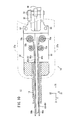
- FIG. 2 is a schematic configuration view of the end effector drive mechanism 320 when the trigger lever is pushed out.
- Fig. 3 is a schematic configuration view of the end effector drive mechanism 320 when the trigger lever is sufficiently pulled.
- Fig. 4 is a perspective view of the tip operating unit 12.
- Fig. 5 is an exploded perspective view of the tip operating unit 12.
- the operation of the end effector drive mechanism 320 is converted into the operation (opening and closing operations) of the end effector 300 by a conversion mechanism 15.
- the conversion mechanism 15 includes a transmitting member 152 that can advance and retreat in the extension direction of the end effector 300, and if the transmitting member 152 moves to the advance position which is the Z1 direction side shown in Fig. 2 , the end effector 300 becomes an opened state (refer to Fig. 7 ), and if the transmitting member 152 moves to the retreat position which is the Z2 direction side shown in Fig. 3 , the end effector 300 becomes a closed state (refer to Fig. 8 ). That is, according to the advance and retreat operations of the transmitting member 152, the end effector 300 is opened and closed.
- the conversion mechanism 15 includes components other than the transmitting member 152. The detailed descriptions thereof will be described.
- the end effector drive mechanism 320 includes a first mechanism 320a that moves the transmitting member 152 to the retreat position when the trigger lever 36 is pulled in the Z2 direction, and a second mechanism 320b that moves the transmitting member 152 to the advance position when the trigger lever 36 is pressed in the Z1 direction.
- a is added to reference numerals of the components of the first mechanism 320a
- b is added to reference numerals of the components of the second mechanism 320b, and both are distinguished from each other.
- components having similar functions in the components in the first mechanism 320a and the components in the second mechanism 320b in order to avoid complication, only the components in the first mechanism 320a may be representatively described.
- the first mechanism 302a includes a connection rod 85 that is connected to the base end side (trigger operator 36b side) of the arm portion 36a of the trigger lever 36 rather than the trigger shaft 39 of the arm portion 36a of the trigger lever 36, a rod 82a that is connected to the Z1 side of the connection rod 85, an idle pulley 140a that is disposed so as to be separated from the Z1 side of the rod 82a, a guide pulley 142a that is disposed so as to be separated from the Z1 side of the idle pulley 140a, a driven pulley 156a that is disposed at the end effector 300 side rather than the guide pulley 142a, and a driven wire 252a that is wound around the idle pulley 140a, the guide pulley 142a, and the driven pulley 156a.
- the idle pulley 140a is configured so that a first layer idle pulley 232A and a second layer idle pulley 232B that can be rotated to be independent from each other are disposed at the same axis as each other.
- the guide pulley 142a is configured so that a first layer guide pulley 236A and a second layer guide pulley 236B that can be rotated to be independent from each other are disposed at the same axis as each other.
- a pin 154 parallel to the shaft 112 is inserted into the transmitting member 152, and the driven pulley 156a is rotatably pivoted with respect to the pin 154. Thereby, the driven pulley 156a and the transmitting member 152 can simultaneously move in the extension direction of the end effector 300 (Z direction when the end effector 300 is a neutral posture).
- a portion of the rod 82a and the driven wire 252a is inserted into the inner portion of the shaft 18.
- the rod 82a is a stainless steel pipe or a solid rod that is sufficiently strong and thin, and a portion of the rod 82a that is close in the Z1 direction is positioned in the inner portion of the shaft 18.
- a portion of the driven wire 252a is an annular (endless shaped) flexible member that is engaged to a wire engagement portion 250a provided at the end of the Z1 side of the rod 82a.
- the driven wire 252a may be a rope, a resin wire, a piano wire, a chain, or the like other than the wire.
- the annulus has a wide sense, and the flexible member does not necessarily need to be applied over the entire length of the driven wire. It is preferable if at least a portion of the driven wire which is wound around each pulley is the flexible member, and it is needless to say that a straight line portion of the driven wire may be connected by a rigid body.
- the driven wire 252a is disposed from the rod 82a toward the X2 direction (second side) through the X1 direction (first side) of the first layer idle pulley 232A, and reaches the surface in the X2 direction of the driven pulley 156a through the surface in the X2 direction of the first layer guide pulley 236A.
- the driven wire 252a is disposed in a path in which the driven wire is wound around a semicircle of the surface in the Z1 direction of the driven pulley 156a, reaches the surface in the X1 direction, through the surface in the X1 direction of the second layer guide pulley 236B, and reaches the wire engagement portion 250a through the X2 direction of the second layer idle pulley 232B toward the X2 direction.
- the idle pulley 140a, the guide pulley 142a, and the driven pulley 156a have approximately the same diameter to one another, and the diameter is appropriately large within a possible range in the layout so that the driven wire 252a is not bent too much.
- the wire engagement portion 250a is provided at a position which is appropriately separated from the idle pulley 140a so that the driven wire 252a is not excessively bent, and both ends of the driven wire 252a form an acute angle with the wire engagement portion 250a as an apex.
- a gap between the idle pulley 140a and the guide pulley 142a is narrow, and for example, a gap approximately the same as the width of the driven wire 252a is formed.
- small flanges may be provided on the upper surfaces and lower surfaces of the idle pulley 140a, the guide pulley 142a, and the driven pulley 156a, and the side surfaces may be formed in a concave shape.
- the arm portion 36a is rotated about the trigger shaft 39 in a counterclockwise direction in Fig. 3 , and therefore, the rod 82a moves in the Z2 direction through the connection rod 85.
- the driven wire 252a connected to the rod 82a moves in the Z2 direction
- the driven pulley 156a moves toward the retreat position (right direction in Fig. 3 ) according to the movement in the Z2 direction of the driven wire 252a.
- the transmitting member 152 moves along with the driven pulley 156a.
- the idle pulley 140a and the guide pulley 142a are configured so that two pulleys having the same axis as each other respectively are disposed in parallel, and therefore, the pulleys can rotate in a reverse direction according to the movement of the driven wire 252a that abuts the pulley, and the operation is smoothly performed.
- the second mechanism 320b includes a configuration in which a return pulley 350 is substantially added to the first mechanism 320a.
- the driven pulley 156a and the driven pulley 156b include a configuration having the same axis as each other.
- the second mechanism 320b includes a wire 87 that is connected further toward a tip side (side opposite to the ring portion 36c based on the trigger shaft 39) than the trigger shaft 39 of the arm portion 36a of the trigger lever 36, a rod 82b that is connected to the Z1 side of the wire 87, an idle pulley 140b that is disposed so as to be separated from the Z1 side of the rod 82b, a guide pulley 142b that is disposed so as to be separated from the Z1 side of the idle pulley 140b, a driven pulley 156b that is disposed at the end effector 300 side rather than the guide pulley 142b, a return pulley 350 that is disposed so as to be separated from the end effector 300 side rather than the driven pulley 156b, and a driven wire 252b that is wound around the idle pulley 140b, the guide pulley 142b, the driven pulley 156b, and the return pulley 350.
- the idle pulley 140b is rotatably pivoted at the shaft 110.
- the idle pulley 140b is configured so that a first layer idle pulley 234A and a second layer idle pulley 234B that can be rotated to be independent from each other are disposed at the same axis as each other.
- the guide pulley 142b is rotatably pivoted at the shaft 112.
- the guide pulley 142b is configured so that a first layer guide pulley 238A and a second layer guide pulley 238B that can be rotated to be independent from each other are disposed at the same axis as each other.
- the driven pulley 156b is rotatably pivoted so as to be independent from and have the same mutual axis as the driven pulley 156a due to the pin 154 in a hole 144a (refer to Fig. 5 ) provided in a main shaft member 144 described below. Thereby, two driven pulleys 156a and 156b and the transmitting member 152 can simultaneously move in the extension direction of the end effector 300.
- the driven pulley 156b has a width in which the driven wire 252b can be wound twice.
- the return pulley 350 is rotatably pivoted by a pin 352 that is disposed in the inner portion of a hollow cylindrical tip cover 161 (refer to Figs. 4 and 5 ), and the position of the return pulley is fixed at the inner portion of the tip cover 161.
- the return pulley 350 has a width in which the driven wire 252b can be wound twice.
- the return pulley 350 is formed in two layers, the two layered pulleys can be rotated in directions opposite to each other at the time of the opening and closing operations, and therefore, friction between the driven wire 252b and the return pulley can be decreased.
- a portion of the rod 82b and the driven wire 252b is inserted into the inner portion of the shaft 18.
- a portion of the driven wire 252b is an annular flexible member that is engaged to a wire engagement portion 250b provided at the end of the Z1 side of the rod.
- the driven wire 252b is disposed from the wire engagement portion 250b of the rod 82b toward the X2 direction through the X1 direction of the first layer idle pulley 234A, and reaches the surface in the X2 direction of the driven pulley 156b through the X2 direction of the first layer guide pulley 238A.
- the driven wire 252b extends toward the Z1 direction as it is, reaches the surface in the X2 direction of the return pulley 350, is wound a half turn around the surface in the Z1 direction of the return pulley 350, and returns in the Z2 direction.
- the driven wire 252b is wound a half turn around the surface in the Z2 direction of the driven pulley 156b, reaches the return pulley 350 again through the X2 side, is wound a half turn around the surface in the Z1 direction of the return pulley 350 again, and returns in the Z2 direction. Thereafter, the driven wire 252b reaches in the X2 direction of the second layer idle pulley 234B from the X1 direction of the second layer guide pulley 238B, and reaches the wire engagement portion 250b of the rod 82b.
- the arm portion 36a is rotated about the trigger shaft 39 in a clockwise direction in Fig. 2 , and therefore, the rod 82b moves in the Z2 direction via the wire 87, according to this, the driven wire 252b connected to the rod 82b is drawn out in the Z2 direction at the place of the wire engagement portion 250b and moves.
- the driven wire 252b is wound around the driven wire 252b via the return pulley 350, the driven pulley 156b moves in the left direction in Fig. 2 .
- the transmitting member 152 also moves along with the driven pulley 156b.
- the first layer idle pulley 234A and the second layer idle pulley 234B rotate in directions opposite to each other, and the first layer guide pulley 238A and the second layer guide pulley 238B rotate in directions opposite to each other.
- the press-pull operation of the trigger lever 36 is converted to the advance and retreat operation of the transmitting member 152.
- the transmitting member 152 performs the advance and retreat operation, and therefore, the opening and closing operations of the end effector 300 are performed.
- the end effector 300 that performs the opening and closing operations through the conversion mechanism 15 is configured as a gripper 300A in the illustrated example.
- the gripper 300A includes a pair of gripper members 308 and is configured as an opening and closing mechanism that can be opened and closed.
- Lever portions 310 are provided on the base end sides of each of the gripper members 308.
- Shaft holes 216 are formed in each of the lever portions 310.
- a hollow cylindrical tip cover 161 is disposed in the Z1 direction side of the shaft 18 as a whole, and a pair of protrusion pieces 304 is provided at the tip of tip cover 161.
- the lever portions 310 of the pair of gripper members 308 are disposed so as to be overlapped with each other between the pair of protrusion pieces 304.
- a pin 196 that is fixed between the pair of protrusion pieces 304 of the tip cover 161 is inserted into the shaft holes 216 of the lever portions 310, and each of the lever portions 310 is rotatably pivoted to the tip cover 161 with an opening and closing axis Og as a center.
- the movable ranges of the gripper members 308 with the opening and closing axis Og as the center may be set so that the gripper 300A is opened to 40° or equal to or more than 40°, for example.
- the conversion member 15 includes a pair of link members 220 that is connected to the lever portions 310 of the pair of gripper members 308 via pins 222, a passive plate 158 that is connected to the link members 220 via pins 224, and the above-described transmitting member 152 that is engaged to be relatively rotated with respect to the passive plate 158.
- Pin holes 218 are formed in the base end of the lever portions 310, pin holes 220a are formed in one set of ends of the link members 220, and the pin 222 is inserted into the pin holes 218 and 220a. Thereby, the link members 220 are rotatably connected to the lever portions 310 of the gripper members 308 via the pin 222.
- Pin holes 220b are formed in the other ends of the link members 220, and the pin 224 is inserted into the pin holes 220b. Thereby, the link members 220 are rotatably connected to a passive plate 158 via the pin 224. Each of the link members 220 is disposed so as to be inclined to the axial line of the tip cover 161 so that one link member 220 crosses the other link members 220 in the intermediate portion in a plan view.
- the passive plate 158 includes a concave portion 166 in the Z2 direction, an engagement portion 168 that is provided on the bottom surface of the concave portion 166, ribs 170 in the axial direction that are each provided at both end surfaces in the X direction, and two link holes 172.
- the engagement portion 168 has a shape that engages with a mushroom shaped protrusion 174 provided at the tip of the transmitting member 152. According to the engagement, the passive plate 158 and the transmitting member 152 can perform the rotation of the relative roll axis.
- the ribs 170 of the passive plate 158 are fitted to two grooves 175 that are formed on the inner surface of the tip cover 161, and therefore, the passive plate 158 is guided in the axial line direction (roll axis Or direction) of the tip cover 161. Since the protrusion 174 that is provided at the tip of the transmitting member 152 engages with the engagement portion 168 of the passive plate 158, the passive plate 158 and the transmitting member 152 can simultaneously move in the axial direction of the tip cover 161 in the inner portion of the tip cover 161.
- the link acts on the lever portions 310 according to the movement of the passive plate 158, and therefore, the gripper 300A is opened as shown in Fig. 7 .
- the transmitting member 152 moves in the retreat direction (right direction in Fig. 8 ) according to the pull operation of the trigger lever 36, the passive plate 158 moves in the same direction, the link members 220 acts on the lever portions 310 according to the movement of the passive plate 158, and therefore, the gripper 300A is closed as shown in Fig. 8 .
- the gripper 300A Since the force that pushes out the trigger lever 36 by hands is directly transmitted by the above-described second mechanism 320b (refer to Fig. 3 ) to the gripper 300A in a mechanical manner, the gripper can be opened not by a predetermined force such as an elastic body but by an arbitrary strong force. Therefore, living body tissues are separated using the outer side surfaces of the gripper 300A, or the gripper can be appropriately used with respect to manipulation such as expansive opening of a hole portion.
- the protrusion 174 that is provided at the tip of the transmitting member 152 engages with the engagement portion 168 of the passive plate 158 so as to be rotated with the roll axis Or as a center.
- the tip cover 161 can rotate to a main shaft member 144 that is pivotally supported so as to be tiltable to the tip of the shaft 18 with the roll axis as a center. Accordingly, the gripper 300A, the link members 220, the passive plate 158, and the tip cover 161 can rotate along with the roll axis Or as a center.
- FIG. 9 is a partial cross-sectional side view of the manipulator main body 11 in a state where the working unit 16 and the operating unit 14 are separated from each other
- Fig. 10 is a cross-sectional plan view in which a portion of the working unit 16 is omitted.
- Two rods 82a and 82b that are components of the above-described end effector drive mechanism 320 penetrate in the Z direction so as to be lined up in the Y direction in a cavity portion 66 that configures the pulley box 32.
- a pair of pinholes 84 and 84 that is symmetrical based on the Z direction is formed at the Z2 side of the pulley box 32.
- a pair of guide pins 86 and 86 that protrudes in the Y1 direction from the bottom surface of the bracket 52 is inserted into each of the pinholes 84 and 84 at the time of the mounting of the working unit 16 and the operating unit 14, and therefore, the operating unit 14 and the working unit 16 are positioned and mounted so as to have high stiffness.
- the drive unit 30 includes the above-described first and second motors 50a and 50b, a bracket 52 that supports the first and second motors 50a and 50b, and a gear mechanism portion 54 that converts the rotation directions of the first and second motors 50a and 50b and transmits the driving force to the working unit 16 side.
- the first and second motors 50a and 50b have a columnar form, output shafts 56a and 56b that are decelerated by a reduction gear (not shown) penetrate one surface of the bracket 52, and driving bevel gears 58a and 58b configuring the gear mechanism portion 54 are fixed to the output shafts 56a and 56b.
- the first and second motors 50a and 50b are DC motors, and a rotary encoder or the like is provided as an angle sensor (not shown).
- the gear mechanism portion 54 is provided in a space within the bracket 52, and includes two drive shafts 60a and 60b that are lined up in the X direction and two driven bevel gears 62a and 62b that are fixed to each of the drive shafts 60a and 60b and engaged with the driving bevel gears 58a and 58b.
- the output shafts 56a and 56b of the first and second motors 50a and 50b, the drive shafts 60a and 60b, and the like are pivotally supported to the bracket 52 through bearings (not shown).
- the lower end side of the drive shaft 60a (60b) protrudes from the lower surface of the bracket 52, and for example, an engaging protrusion 64a (64b) that has a cross-section of a hexagonal waveform and a taper shape with a tapered tip is provided in the tip of the protruded lower end.
- the pulley box 32 includes a cavity portion 66 in which both ends are opened in the X direction, and pulleys (driven shafts) 70a and 70b and wire guide portions 72a and 72b that are accommodated in the cavity portion 66, and the shaft 18 are fixed and supported to a hole portion that penetrates the Z1 side of the cavity portion 66.
- the pulleys 70a and 70b have the same axis as the drive shafts 60a and 60b, and engaging recesses 74a and 74b that can engage with the engaging protrusions 64a and 64b of the drive shafts 60a and 60b side are provided at the upper end side of the pulleys.
- the engaging recesses 74a and 74b can engage with (fit to) the engaging protrusions 64a and 64b and for example, include a concave portion that has a cross-section of a hexagonal waveform and a taper shape having a tapered inner portion.
- the engaging protrusion 64a (64b) and the engaging recess 74a (74b) engage with each other, and therefore, the rotation driving force from the drive shaft 60a (60b) can be transmitted to the pulley 70a (70b).
- an attachment and detachment detection sensor (not shown) that detects the attachment and detachment of the operating unit 14 and the working unit 16
- a phase detection sensor (not shown) that detects a phase of the drive shaft 60a, or the like
- the engagement structure of the engaging protrusion 64a or the engaging recess 74a may have another structure.
- the wire guide portions 72a and 72b are disposed at the Z1 side of the pulleys 70a and 70b, and an interval between the outer circumferential surfaces of the wire guide portions is set so as to be narrower than the interval between the outer circumferential surfaces of the pulleys 70a and 70b.
- Wires (a power transmitting member) 80a and 80b are wound around the pulleys 70a and 70b, are guided by wire guide portions 72a and 72b, and are inserted into the shaft 18.
- the shaft 18 can be sufficiently thin without depending on diameters of the first and second motors 50a and 50b or an axial distance between the pulleys 70a and 70b, and for example, the shaft can be easily set to an outer diameter of approximately 5 mm to 10 mm that is suitable to be inserted into the trocar 20.
- Fig. 11 is a schematic configuration view of a mechanism for transmitting the driving force of the drive unit 30 to the posture change mechanism 13 (refer to Figs. 6 to 8 ).
- the above-described shaft 112 (refer to Figs. 2 and 6 ) that pivotally supports the guide pulleys 142a and 142b is provided at the tip of the shaft 18, and each of the wires 80a and 80b is wound around a gear body (second rotation body) 126 and a pulley (first rotation body) 130 that are rotatably pivoted through the shaft 112.
- the gear body 126 and the pulley 130 are components of the posture change mechanism 13.
- each of wires 80a and 80b is reciprocated between the pulleys 70a and 70b side and the tip operating unit 12 side, and therefore, total four wires 80a and 80b and two rods 82a and 82b are inserted into the hollow space of the shaft 18.
- all power transmission mechanisms may be configured by only wires instead of the rods.
- Each of wires 80a and 80b may be the same kind as or different kind from each other, may have the same diameter as or different diameter from each other, and is configured of a bendable wire having flexibility.
- a linear portion in which the flexibility is not needed in a portion passing through the inner portion of the shaft 18 is surrounded by a reinforcement rod having high stiffness (not shown) and may be reinforced.
- the tip operating unit 12 includes the end effector 300, the conversion mechanism 15, and the posture change mechanism 13 which are described above.
- the posture change mechanism 13 can perform a roll operation of rotation about the roll axis Or (identical with Z axis at the time of neutral posture) oriented toward the extension direction of the end effector 300 and the yaw operation (tilting operation) of tilting about the yaw axis Oy in the Y direction, and can perform the roll operation and the tilting operation selectively or in combination.
- the roll operation through the posture change mechanism 13 is set so as to rotate the end effector 300 about the roll axis Or in the extension direction of the end effector 300, and for example, includes a movable range that is ⁇ 180° or equal to or more than ⁇ 180°.
- the tilting operation through the posture change mechanism 13 is set so as to be swung in the direction that crosses the axial line along the extension direction of the shaft 18, and for example, includes a movable range that is ⁇ 90° or equal to or more than ⁇ 90°.
- the posture change mechanism 13 includes the main shaft member 144 in which the pulley 130 driven to rotate through the first motor 50a via one wire (first transmitting member) 80a and can rotate about the yaw axis (tilt axis) Oy which is not parallel to the axial line of the shaft 18, the gear body 126 that is driven to rotate through the second motor 50b via the other wire (second transmitting member) 80b, and a gear body 146 (third rotation body) that is driven by the gear body 126 and is supported to the main shaft member 144 so as to be rotated about the roll axis Or in the extension direction of the end effector 300.
- the gear body 126 and the main shaft member 144 are rotatably supported by the shaft 112 that is provided at the tip of the shaft 18.
- a pair of protrusion pieces 58 (refer to Fig. 5 ) that protrude in the Z1 direction is provided in both sides in the Y direction of the tip of the shaft 18, and the shaft 112 is fixed between the pair of protrusion pieces 58 along the Y direction.
- the gear body 126 includes a barrel 132, and a gear 134 that is concentrically provided on the upper portion of the barrel 132.
- the pulley 130 has the approximately similar diameter and the approximately similar shape to the barrel 132 of the gear body 126.
- a portion of the wires 80a and 80b are fixed to and wound around the pulley 130 and the barrel 132 by predetermined fixing means.
- an angle through which the wires 80a and 80b are wound is 1.5 rotations (540°).
- the pulley 130 is integrally provided on the base end side of the main shaft member 144, and the main shaft member 144 is supported to be rotatable (to be tiltable) about the yaw axis through the shaft 122. Accordingly, the pulley 130 is driven to rotate by the wire 80a, and therefore, the main shaft member 144 in which the pulley 130 is integrally provided rotates about the yaw axis Oy.
- Two accessory plates 144b and 144b (refer to Fig. 5 ) that are rotatably supported by the shaft between the pulley 130 and the gear body 126 are provided at the end in the Z2 direction in the main shaft member 144.
- the accessory plates 144b and 144b are held on the upper surface in the Y direction of the guide pulley 142a and on the lower surface in the Y direction of the guide pulley 142b.
- a tubular portion 144d that protrudes from the accessory plates 144b and 144b toward the end effector 300 is provided at the end in the Z1 direction in the main shaft member 144.
- a square hole 144a that extends in the roll axis Or direction is provided in an axial center portion of the main shaft member 144, the transmitting member 152 which is a component of the above-described conversion mechanism 15 is inserted into the hole 144a, and therefore, the transmitting member 152 is guided so as to advance and retreat in the roll axis direction.
- a shaft hole 354 in the radial direction to which the pin 352 is inserted and fixed is provided in the main shaft member 144.
- the shaft hole 354 penetrates the tubular portion 144d of the main shaft member 144 via the hole 144a.
- a long hole 356 that extends in the axial direction while having a width at which the pin 352 can be inserted is provided in the transmitting member 152.
- the transmitting member 152 is provided at a position which is slightly offset in the Y1 direction from the roll axis. However, only the protrusion 174 of the tip may be positioned at the axial center. Of course, the transmitting member 152 may be positioned on the roll axis.
- the gear body 146 is rotatably supported to the outer circumference of the tubular portion 144d of the main shaft member 144.
- the slip-off of the gear body 146 to the main shaft member 144 is prevented by a nut body 148.
- a thrust bearing member 144c made of resin is provided in a portion of the main shaft member 144 that abuts the gear body 146.
- a thrust bearing member 148a made of resin is provided in a portion of the nut body 148 that abuts the gear body 146.
- the thrust bearing members 144c and 148a consist of a low friction material, decrease the friction and torque of the abutted portion, and prevent a load from being directly applied to a face gear 165.
- the thrust bearing members 144c and 148a are a so-called sliding bearing, however, a rolling bearing may be provided. Thereby, when the gripper 300A is strongly opened or closed, that is, when the gear body 146 strongly abuts the main shaft member 144, the roll operation can be smoothly performed.
- the gear body 146 is a tubular shape with a step, and includes a large diameter portion 162 in the Z2 direction, a small diameter portion 164 in the Z1 direction, and the face gear 165 that is provided at the end surface in the Z2 direction of the large diameter portion 162.
- the face gear 165 engages with the gear 134.
- a screw portion that screws to a screw portion provided at the end in the Z2 direction side of the tip cover 161 is provided on the outer circumference of the large diameter portion 162.
- the base end of the tip cover 161 is connected (screwed, press-fitted, or the like) so as to be externally fitted to the gear body 146, and the tip cover 161 and the end effector 300 perform the roll operation according to the rotation of the gear body 146.
- a composite mechanism portion 102 that performs the opening and closing operations of the end effector 300 and the posture change of the end effector 300 is configured.
- the pulley 130 and the gear body 126 can be rotated with respect to the shaft 112. If the pulley 130 is rotated, the tilting operation of the end effector 300 is performed. That is, the main shaft member 144 in which the pulley 130 is integrally provided rotates about the yaw axis Oy, and the gear body 146, the tip cover 161, and the end effector 300 are tilted about the yaw axis Oy so as to be integral with the main shaft member 144.
- the roll operation of the end effector 300 is performed. That is, if the gear body 146 rotates about the roll axis Or by the gear body 126, the tip cover 161 and the end effector 300 rotate about the roll axis Or to be integral with the gear body 146.
- the composite input unit 24 that electrically drives the tip operating unit 12 has a structure that is symmetrical in the X1 and X2 directions with the Z axis (Y axis) as a center and is a composite input unit that issues a rotation command in the roll direction (axis rotation direction) and the yaw direction (left and right directions) with respect to the tip operating unit 12.
- the composite input unit 24 is supported by a sensor holder 88 that is disposed on the inclined plane 26a, and includes a rotation operating unit 90 of the Z1 side (Y1 side) of the inclined plane 26a, a tilting operating unit 92 that is provided at the Z2 side (Y2 side), and three switch operators 94a to 94c that are disposed on the surface of the lower portion side of the tilting operating unit 92 respectively.
- the operation amount in the input to the rotation operating unit 90 or the like is detected by a switch substrate (not shown) or the like that is provided in the sensor holder 88, and the first and second motors 50a and 50b are appropriately driven and controlled under the control of the controller 29.
- the push-out position of the trigger lever 36 means a position at which the trigger lever 36 is sufficiently pushed out (a position in which the trigger lever 36 is most rotated in the Z1 direction side in the movable range of the trigger lever 36) or a position in the vicinity thereof
- the pulling position of the trigger lever 36 means a position in which the trigger lever 36 is sufficiently pulled (a position in which the trigger lever 36 is most rotated in the Z2 direction side in the movable range of the trigger lever 36) or a position in the vicinity thereof.
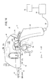
- Fig. 13 when the trigger lever 36 is located at the push-out position is shown by a solid line, and when the trigger lever 36 is located at the pulling position is shown by a two-dot chain line.
- the manipulator 10 further includes the detection mechanism 400 that detects an operation state of the trigger lever 36 which is a first input unit.
- the detection mechanism 400 according to the first configuration example is configured so as to detect that the trigger lever 36 has reached the pulling position. That is, the detection mechanism 400 detects that the trigger lever 36 reaches the operation position corresponding to a state where the gripper 300A which is the end effector 300 is closed or a state where the gripper is substantially closed.
- the detection mechanism 400 includes a protrusion (protrusion piece for detection) 402 that is provided in the trigger lever 36 and a detecting unit 404 that is provided in the operating unit 14.
- the protrusion 402 is fixed to (is provided in) the arm portion 36a of the trigger lever 36, and in the illustrated example, the protrusion is provided so as to protrude in the Z2 direction and operates along with the trigger lever 36. That is, if the trigger lever 36 swings in the front and rear directions (Z direction), the protrusion 402 also swings with the trigger shaft 39 as a rotation supporting point.
- the detecting unit 404 is provided at a position opposite to the end in the Z2 direction side of the lower covers 37a and 37b of the operating unit 14, detects the protrusion 402 in a state where the working unit 16 is mounted on the operating unit 14, and therefore, detects that the trigger lever 36 reaches the above-described pulling position.
- Fig. 14A is a schematic configuration view when the protrusion 402 and the detecting unit 404 are viewed from the Z2 direction side when the trigger lever 36 is located at the push-out position in Fig. 13 .
- Fig. 14B is a schematic configuration view when the protrusion 402 and the detecting unit 404 are viewed from the Z2 direction side when the trigger lever 36 is located at the pulling position in Fig. 13 .
- a space 405 to which the protrusion 402 can enter and which is concave in the Y1 direction is provided between the left and right upper covers 25a and 25b.
- the space 405 and an inner portion 19 of the upper covers 25a and 25b are spatially separated from each other by the walls of the upper covers 25a and 25b.
- the detecting unit 404 includes an operating body 406 that is pressed by the protrusion 402 and moves in the X direction, a tact switch 408 that is pressed by the operating body 406, a switch substrate 409 in which the tact switch 408 is provided, and a switch cover 410 that covers the tact switch 408 and is formed of a flexible material capable of being elastically deformed (for example, silicone rubber).
- the operating body 406 is inserted into a hole 412 that is provided in the upper cover 25b and is guided to be movable in the X direction through the hole 412.
- a locking member 411 is fixed to the outer circumference of the inner portion side of the operating body 406, and due to the locking member 411, the operating body 406 is prevented from slipping out to the space 405 side from the upper covers 25a and 25b.
- a seal member (O-ring in the illustrated example) 413 is disposed between the inner circumferential surface of the hole 412 and the outer circumferential surface of the operating body 406, and due to the seal member 413, penetration of liquid or dust from the space 405 side to the inner portion 19 of the upper covers 25a and 25b is prevented.
- the switch substrate 409 is electrically connected to the controller 29 via the cable 28 (refer to Fig. 13 ), and signals output from the switch substrate 409 are sent to the controller 29.
- a taper surface 403 that is inclined in the X direction is provided in the protrusion 402, the protrusion 402 moves in the Y1 direction, and if the taper surface 403 and one end (end in the X direction) of the operating body 406 abut each other, the operating body 406 is pressed in the X2 direction by the taper surface 403 and moves.
- the taper surface that is inclined in the X direction may be provided in one end of the operating body 406, or the taper surface may be provided to both the protrusion 402 and operating body 406.
- the detecting unit 404 does not detect the protrusion 402.
- the trigger lever 36 is operated so as to rotate in the Z2 direction and reaches the pulling position, as shown in Fig. 14B , the protrusion 402 presses the operating body 406 and moves the operating body in the X2 direction. Therefore, the tact switch 408 is pressed through the switch cover 410 and detects that the trigger lever 36 has reached the pulling position. That is, signals corresponding to being pressed are output from the tact switch 408, the signals are sent to the controller 29, and therefore, the trigger lever 36 reaching the pulling position is recognized in the controller 29.
- the signals from the detecting unit 404 are sent to the controller 29, the frequency is counted, which is stored as use history data for each identification number of the working unit 16. That is, in the manipulator 10, the operation frequency of the trigger lever 36 is detected and stored, and life span prediction and the like of the mechanism (end effector drive mechanism 320 or the like) that mechanically transmits a force based on the trigger lever 36 itself or the operation of the trigger lever 36 can be performed using the operation frequency.
- the controller 29 transmits the signals from the detecting unit 404 to the host computer 31, and the operation frequency of the trigger lever 36 may be stored as the use history data for each identification number of the working unit 16 in the host computer 31.
- the detection mechanism 400 shown in Fig. 13 is configured so as to detect that the trigger lever 36 has reached the pulling position. However, instead of this, the detection mechanism may be configured so as to detect that the trigger lever 36 reaches the push-out position. Even though the detection mechanism is configured in this way, similar to the above-described that, the operation frequency of the trigger lever 36 is detected, and the life span prediction or the like can be performed.
- the detection mechanism 400 may be configured so as to detect both when the trigger lever 36 reaches the pulling position and when the trigger lever 36 reaches the push-out position.
- a second detecting unit having the similar configuration to the above-described detecting unit 404 may be provided at a position where the protrusions 402 can be detected when the trigger lever 36 reaches the push-out position. According to such configuration, the reaching of the trigger lever 36 is detected at a plurality of positions, a more detailed use state can be ascertained, and reliability of the life span prediction or the like is improved.
- the detection mechanism 400 since the operation of the trigger lever 36 is transmitted to the detecting unit 404 that is provided in the operating unit 14 via the protrusion 402, electronic equipment for detecting the operation angle of the trigger lever 36 need not be provided in the working unit 16. Thereby, the working unit 16 can be easily cleaned and sterilized.
- the protrusion 402 may be provided in the trigger operator 36b, and the detecting unit 404 may be provided in the grip handle 26.
- the tip operating unit 12 includes the conversion mechanism 15 that converts the operation of the end effector drive mechanism 320 based on the operation of the trigger lever 36 to the opening and closing operations of the end effector 300, and the posture change mechanism 13 that changes the posture of the end effector 300 by the driving of the drive unit based on the operation of the composite input unit 24.
- the end effector drive mechanism 320 draws the conversion mechanism 15 in the Z2 direction, and the gear body 146 which is the third rotation body is pressed to the main shaft member 144 in the axial direction (right direction in Fig. 8 ) via the conversion mechanism 15.
- the rotation resistance of the gear body 146 becomes large.
- the end effector drive mechanism 320 presses the conversion mechanism 15 in the Z1 direction, and the gear body 146 which is the third rotation body is pressed to the main shaft member 144 in the axial direction (left direction in Fig. 7 ) via the conversion mechanism 15.
- the rotation resistance of the gear body 146 becomes large.
- driving torque of the second motor 50b acts on not only torque that rotates the gear body 146 with the roll axis Or as a center but also driving torque (wire 80a) of the first motor 50a as interference torque. That is, the driving force of the second motor also acts as the torque that rotates the main shaft member 144 with the yaw axis Oy as a center.
- the driving torque of the motor 50a receives the torque that rotates the main shaft member 144 with the yaw axis Oy as a center.
- the driving torque of the motor 50a (tension of wire 80a) receives the torque that rotates the main shaft member 144 with the yaw axis Oy as a center.
- stiffness of the driving system is not sufficient (for example, elongation of wire)
- a decrease of trajectory accuracy or positioning accuracy of the tip operating unit 12 may occur due to the interference torque of the mechanism.
- a control that compensates for the interference torque through a feed forward control or the like may be performed.
- the control according to the rotation resistance of the gear body 146 with respect to the main shaft member 144 that is, the control according to the interference torque can be performed.
- the gear body 146 is rotated about the roll axis Or for the roll operation in a state where the end effector 300 is largely and strongly opened, since the interference torque is increased, the effect of the tilting operation is increased.
- the controller 29 controls the first motor 50a for driving the pulley 130 in order to prevent or suppress the generation of the tilting operation due to the roll operation according to the operation state of the trigger lever 36 based on the detection result from the detection mechanism 400.
- the controller 29 performs the control for the roll operation, in the case where the trigger lever 36 is positioned at the end of the movable range or the vicinity thereof (when the trigger lever 36 is located at the pulling position or the push out position), a compensation control corresponding to the increase of the rotation resistance of the gear body 146 is performed with respect to the first motor 50a for driving the pulley 130 in order to prevent or suppress the generation of the tilting operation.
- the control which is performed by the controller 29 assumes that the detection mechanism 400 is configured so as to detect the trigger lever 36 reaching the push-out position.
- the controller 29 applies a general control command corresponding to the roll operation to the motor 50a.
- the controller 29 controls the first motor 50a while adding a corrected value corresponding to the increase of the rotation resistance of the gear body 146 to the general control command value, the effect of the tilting operation is decreased, and only the roll operation is performed.
- the trigger lever is positioned at positions other than the pulling position or the push out position, since the interference torque is not zero, the corresponding corrected value is added to the control command, and the first motor 50a may be controlled.
- the rotation resistance of the gear body 146 is increased due to the operation of the trigger lever 36, the trajectory accuracy or the positioning accuracy of the tip operating unit 12 at the time of the roll operation can be effectively improved.
- the detection mechanism 420 is similar to the detection mechanism 400 according to the first configuration example in that the detection mechanism 420 includes a protrusion 422 (protrusion piece for detection) that is provided in the trigger lever 36 and a detecting unit 424 that is provided in the operating unit 14, the protrusion 422 is fixed (provided) to the arm portion (refer to Fig. 13 ) of the trigger lever 36 and is configured so as to detect that the trigger lever 36 has reached the pulling position.
- the detection mechanism 420 is different from the detection mechanism 400 in the configuration of the detecting unit 424. That is, the detecting unit 424 of the detection mechanism 420 is configured from a photosensor that includes a light projector 424a and a light receiver 424b.
- the detecting unit 424 configured in this way, when the trigger lever 36 is located at the push-out position, as shown in Fig. 15A , since the protrusion 422 is retreated from the detecting unit 424, the detecting unit 424 does not detect the protrusion 422. On the other hand, if the trigger lever 36 is operated so as to rotate in the Z2 direction in Fig. 13 and reaches the pulling position, as shown in Fig. 15B , since the protrusion 422 enters between the light projector 424a and the light receiver 424b and interrupts light from the light projector 424a, the trigger lever 36 reaching the pulling position is detected. That is, the controller 29 recognizes that the light is interrupted, and thereby, the trigger lever 36 reaching the pulling position is detected.
- the detection mechanism 420 is configured so as to detect that the trigger lever 36 has reached the pulling position. However, instead of this, the detection mechanism may be configured so as to detect that the trigger lever 36 reaches the push-out position. In addition, the detection mechanism 420 may be configured so as to detect both when the trigger lever 36 reaches the pulling position and when the trigger lever 36 reaches the push-out position.
- the protrusion 422 may be provided in the trigger operator 36b (refer to Fig. 13 ), and the detecting unit 424 may be provided in the grip handle 26.
- the controller 29 controls the motor 50a in order to prevent or suppress the generation of the tilting operation due to the roll operation according to the operation state of the trigger lever 36 based on the detection result from the detection mechanism 420.
- the controller 29 controls the motor 50a in order to prevent or suppress the generation of the tilting operation due to the roll operation according to the operation state of the trigger lever 36 based on the detection result from the detection mechanism 420.
- a detection mechanism 430 according to a third configuration example will be described.
- the trigger lever 36 when the trigger lever 36 is located at the push-out position, the trigger lever 36 is shown by a solid line, and when the trigger lever 36 is located at the pulling position, the trigger lever 36 is shown by a two-dot chain line.
- the detection mechanism 430 according to the third configuration example is configured so as to detect that the trigger lever 36 has reached the pulling position.
- the detection mechanism 430 includes a cam body (protrusion piece for detection) 432 that is provided in the trigger lever 36 and a detecting unit 434 that is provided in the operating unit 14.
- the cam body 432 is fixed to (is provided in) the arm portion of the trigger lever 36, and in the illustrated example, the cam body is provided so as to protrude in the Z2 direction and operates along with the trigger lever 36. That is, if the trigger lever 36 swings in the front and rear directions (Z direction), the cam body 432 also swings with the trigger shaft 39 as a rotation supporting point.
- the detecting unit 434 is provided at a position opposite to the cam body 432, detects the cam body 432 in the state where the working unit 16 is mounted on the operating unit 14, and therefore, detects that the trigger lever 36 reaches the above-described pulling position.
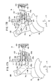
- Fig. 17A is an enlarged configuration view in which a portion of the detection mechanism 430 and the vicinity thereof are omitted when the trigger lever 36 is located at the push-out position in Fig. 16 .
- Fig. 17B is an enlarged configuration view in which a portion of the detection mechanism 430 and the vicinity thereof are omitted when the trigger lever 36 is located at the pulling position in Fig. 16 . As shown in Figs.
- the detecting unit 434 includes an operating rod 436 that is pressed by the cam body 432 and moves in the Z direction, a cylindrical guide member 442 into which the operating rod 436 is inserted and which guides the movement of the operating body, a tact switch 438 that is pressed by the operating rod 436, a switch substrate 439 in which the tact switch 438 is provided, and a switch cover 440 that covers the tact switch 438 and is formed of a flexible material capable of being elastically deformed (for example, silicone rubber).
- a flexible material capable of being elastically deformed for example, silicone rubber
- the operating rod 436 includes a shaft portion 436a which is inserted into the cylindrical guide member 442 and in which a portion protrudes the tact switch 438 side, and a head portion 436b that is provided in the cam body 432 side rather than the shaft portion 436a and is exposed from a partition 17 which is a portion of the upper covers 25a and 25b to the cam body 432 side.
- a flange portion 436c is provided on the outer circumference of the shaft portion 436a and a seal member (O-ring in the illustrated example) 450 is disposed between the flange portion 436c and the head portion 436b.
- the seal member 450 liquid-tightly seals between the outer circumference of the operating rod 436 and the inner circumference of the cylindrical guide member 442.
- a coil spring 446 that elastically biases the operating rod 436 toward the cam body 432 side is provided in the inner portion of the cylindrical guide member 442.
- One end of the coil spring 446 abuts the flange portion 436c of the operating rod 436, and the other end thereof abuts a shoulder that is formed in the inner portion of the cylindrical guide member 442.
- a locking member 437 is fixed to the shaft portion 436b of the operating rod 436, and due to the locking member 437, the operating rod 436 is prevented from slipping out to the cam body 432 side from the cylindrical guide member 442.
- the cylindrical guide member 442 has a hollow cylindrical shape and is inserted into a hole portion 449 that is provided in the partition 17, and a nut 444 is screwed to a screw portion that is provided on the outer circumference of the cylindrical guide member 442 in the inner portion of the upper covers 25a and 25b. Thereby, the cylindrical guide member 442 is fixed to the partition 17.
- a seal member (O-ring in the illustrated example) 448 is disposed between the partition 17 and the cylindrical guide member 442, and the inner circumferential surface of the hole portion 449 and the outer circumferential surface of the cylindrical guide member 442 are liquid-tightly sealed by the seal member 448.
- the switch substrate 439 is electrically connected to the controller 29 via the cable, and signals output from the switch substrate 439 are sent to the controller 29.
- a cam surface 432a that abuts the head portion 436b of the operating rod 436 is provided on the cam body 432.
- an inclined portion 432b that is inclined so as to close in the Y2 direction toward the Z2 direction and is continuous to the cam surface 432a is provided on the cam body 432.
- the detecting unit 434 that is configured as described above, when the trigger lever 36 is located at the push-out position, as shown in Fig. 17A , since the cam body 432 does not insert the operating rod 436 in the Z2 direction, the tact switch 438 is not pressed to the operating rod 436.
- the trigger lever 36 is rotated in the Z2 direction and reaches the pulling position, as shown in Fig. 17B , since the cam body 432 presses the operating rod 436 and moves in the Z2 direction, and the tact switch 438 is pressed through the switch cover 440 and detects that the trigger lever 36 has reached the pulling position. That is, signals corresponding to being pressed are output from the tact switch 438, the signals are sent to the controller 29, and therefore, the trigger lever 36 reaching the pulling position is recognized in the controller 29.
- the working unit 16 can be mounted on the operating unit 14. Even when the trigger lever 36 is located at the pulling position, the working unit 16 is mounted on the operating unit 14, the tip of the operating rod 436 contacts the inclined portion 432b of the cam body 432 and is inserted in the Z2 direction, and at the time of the mounting completion, the trigger lever 36 being located at the pulling position can be detected.
- the detection mechanism 430 of the illustrated example is configured so as to detect that the trigger lever 36 has reached the pulling position. However, instead of this, the detection mechanism may be configured so as to detect that the trigger lever 36 has reached the push-out position. In addition, the detection mechanism 430 may be configured so as to detect both when the trigger lever 36 reaches the pulling position and when the trigger lever 36 reaches the push-out position.
- the cam body 432 may be provided in the trigger operator 36b, and the detecting unit 434 may be provided in the grip handle 26.
- the signals from the detecting unit 434 are sent to the controller 29, the frequency is counted, which is stored as use history data for each identification number of the working unit 16.
- the controller 29 transmits the signals from the detecting unit 434 to the host computer 31, and the operation frequency of the trigger lever 36 may be stored as the use history data for each identification number of the working unit 16 in the host computer 31.
- the detection mechanism 430 the trigger lever 36 reaching the pulling position or the push-out position as the operation state of the trigger lever 36 is detected. Accordingly, similar to the manipulator 10 that includes the detection mechanism 400 according to the first configuration example, ascertainment and analysis of the operation frequency or the like of the trigger lever 36 can be performed, and the life span prediction and the like of the end effector drive mechanism 320 and the like can be performed.
- the detection mechanism 430 since the operation of the trigger lever 36 is transmitted to the detecting unit 434 that is provided in the operating unit 14 via the cam body 432, electronic equipment for detecting the operation angle of the trigger lever 36 need not be provided in the working unit 16. Thereby, the working unit 16 can be easily cleaned and sterilized.
- the controller 29 controls the first motor 50a in order to prevent or suppress the generation of the tilting operation due to the roll operation according to the operation state of the trigger lever 36 based on the detection result from the detection mechanism 430.
- the controller 29 controls the first motor 50a in order to prevent or suppress the generation of the tilting operation due to the roll operation according to the operation state of the trigger lever 36 based on the detection result from the detection mechanism 430.
- the detection mechanism 430a is similar to the detection mechanism 430 according to the third configuration example in that the detection mechanism 430a includes the cam body 432 (protrusion piece for detection) that is provided in the trigger lever 36 and a detecting unit 434a that is provided in the operating unit 14, the cam body 432 is fixed (is provided) to the arm portion 36a (refer to Fig. 16 ) of the trigger lever 36 and is configured so as to detect that the trigger lever 36 has reached the pulling position.
- the detecting unit 434a of the detection mechanism 430a is not a tact switch, and includes a photosensor 460 that is configured of a light projector 460a and a light receiver 460b.
- the detecting unit 434a configured in this way, when the trigger lever 36 is located at the push-out position, as shown in Fig. 18A , since the cam body 432 does not insert the operating rod 436 in the Z2 direction, the operating rod 436 does not interrupt the light from the light projector 460a.
- the trigger lever 36 is operated so as to rotate in the Z2 direction and reaches the pulling position, as shown in Fig. 18B , since the protrusion enters between the light projector 460a and the light receiver 460b and interrupts light from the light projector 460a, the trigger lever 36 reaching the pulling position is detected. That is, the controller 29 recognizes that the light is interrupted, and thereby, the trigger lever 36 reaching the pulling position is detected.
- the working unit 16 can be mounted on the operating unit 14. Even when the trigger lever 36 is located at the pulling position, the working unit 16 is mounted on the operating unit 14, the tip of the operating rod 436 contacts the inclined portion 432b of the cam body 432 and is inserted in the Z2 direction, and at the time of the mounting completion, the trigger lever 36 being located at the pulling position can be detected.
- the detection mechanism 430a of the illustrated example is configured so as to detect that the trigger lever 36 has reached the pulling position. However, instead of this, the detection mechanism may be configured so as to detect that the trigger lever 36 has reached the push-out position. In addition, the detection mechanism 430a may be configured so as to detect both when the trigger lever 36 reaches the pulling position and when the trigger lever 36 reaches the push-out position.
- the cam body 432 may be provided in the trigger operator 36b, and the detecting unit 434a may be provided in the grip handle 26.
- the trigger lever 36 reaching the pulling position or the push-out position as the operation state of the trigger lever 36 is detected. Accordingly, similar to the manipulator 10 that includes the detection mechanism 400 according to the first configuration example, ascertainment and analysis to the operation frequency or the like of the trigger lever 36 can be performed, and the life span prediction and the like of the end effector drive mechanism 320 and the like can be performed.
- the detection mechanism 430a since the operation of the trigger lever 36 is transmitted to the detecting unit 434a that is provided in the operating unit 14 via the cam body 432, electronic equipment for detecting the operation angle of the trigger lever 36 need not be provided in the working unit 16. Thereby, the working unit 16 can be easily cleaned and sterilized.
- the controller 29 controls the motor 50a in order to prevent or suppress the generation of the tilting operation due to the roll operation according to the operation state of the trigger lever 36 based on the detection result from the detection mechanism 430a.
- the controller 29 controls the motor 50a in order to prevent or suppress the generation of the tilting operation due to the roll operation according to the operation state of the trigger lever 36 based on the detection result from the detection mechanism 430a.
- the tact switch or the photosensor is used as the detection means of the detecting unit.
- other detection means such as a magnetic sensor and a proximity sensor may be used.
- a detection mechanism 470 according to a fifth configuration example will be described.
- Fig. 19 is a side view of the manipulator 10 that includes the detection mechanism 470
- Fig. 20 is a plan view in which a portion of the manipulator 10 that includes the detection mechanism 470 is omitted.
- the detection mechanism 470 according to the fifth configuration example is configured so as to detect the operation direction of the trigger lever 36, that is, the position in the rotation direction.
- the trigger lever 36 includes a movable range of an angle ⁇ from the most advance position P1 in which the trigger lever is most rotated in the Z1 side to the most retreat position P2 in which the trigger lever is most rotated in the Z2 side.
- the detection mechanism 470 includes a drive element 472 that is operated along with the trigger lever 36, a driven element 474 that operates in conjunction with the drive element 472 in the state where the working unit 16 provided in the operating unit 14 is mounted on the operating unit 14, and a detecting unit 476 that detects the position in the operation direction of the driven element 474.
- the drive element 472 is a first gear portion 472A that includes teeth extending in the circumferential direction around the rotation axial center of the trigger lever 36
- the driven element 474 is a second gear portion 474A that is rotatably provided in the operating unit 14 and meshes with the first gear portion 472A in the state where the working unit 16 is mounted on the operating unit 14
- the detecting unit 476 is a rotation detector 476A that detects the rotation angle of the second gear portion 474A.
- the first gear portion 472A is provided so as to rotate along with the trigger lever 36. That is, the first gear portion 472A is fixed to the trigger shaft 39 that rotates along with the trigger lever 36, and if the trigger lever 36 rotates in the front and rear direction (Z direction), the first gear portion 472A also rotates with the trigger shaft 39 as a rotation supporting point.
- the teeth are formed on the entire circumference. However, if the first gear portion can mesh with the second gear portion 474A over the entire movable range of the trigger lever 36, the teeth can be formed on only a portion of the outer circumference.
- the second gear portion 474A is provided in the side surface of the upper cover 25b.
- the rotation detector 476A is provided in the inner portion 19 of the upper covers 25a and 25b.
- the second gear portion 474A and the rotation detector 476A are connected to each other via a shaft 480 that penetrates the upper covers 25a and 25b.
- a seal member (O-ring in the illustrated example) 478 is disposed between the upper covers 25a and 25b and the shaft, and due to the seal member 478, entering of the liquid or dust from the outside to the inner portion 19 of the upper covers 25a and 25b is prevented.
- rotation detector 476A a rotary encoder, a potentiometer, a resolver, or the like may be used.
- An incremental encoder and an absolute encoder may be used as the rotary encoder, and any encoder may be used.
- the rotation detector 476A is electrically connected to the controller 29 via the cable 28, and signals output from the rotation detector 476A are sent to the controller 29.
- the first gear portion 472A provided in the trigger lever 36 rotates about the trigger shaft 39 so as to be integral with the trigger lever 36.
- the second gear portion 474A that meshes with the first gear portion 472A rotates, the rotation angle of the second gear portion 474A is detected through the rotation detector 476A, and the operation angle of the trigger lever 36 is detected. That is, signals corresponding to the rotation angle are output from the rotation detector 476A, the signals are transmitted to the controller 29, and the operation angle of the trigger lever 36 is calculated based on the signals from the rotation detector 476A.
- the rotation detector 476A when the rotation detector 476A is the incremental encoder, only pulses corresponding to the change of the rotation angle are output from the incremental encoder, and the absolute angle of the trigger lever 36 cannot be directly detected.
- the controller 29 estimates (calculates) the absolute angle of the trigger lever 36 based on the movable range ⁇ of the trigger lever 36 and the rotation angle range detected by the rotation detector 476A at the time of the use of the manipulator 10. In this way, since the absolute angle of the trigger lever 36 is estimated from the detected signals of the incremental encoder, the detection of the operation angle of the trigger lever 36 can be performed through the simple configuration.
- the operation angle of the trigger lever 36 is detected for each predetermined sampling timing during the use of the manipulator 10, which is stored as use history data for each identification number of the working unit 16. That is, in the manipulator 10, the operation frequency or the use state of the trigger lever 36 is detected and stored, and life span prediction and the like of the mechanism (end effector drive mechanism 320 or the like) (refer to Fig. 2 ) that mechanically transmits a force based on the trigger lever 36 itself or the operation of the trigger lever 36 can be performed using the operation frequency or the use state.
- the detection mechanism 470 since the operation angle of the trigger lever 36 is detected, compared to the detection mechanisms 400, 420, 430, and 430a according to the first to fourth configuration examples, it is possible to ascertain the use state of the trigger lever 36 in more detail, and the reliability of the life span prediction or the like is improved.
- the controller 29 transmits the signals from the detecting unit 476 to the host computer 31, and the operation frequency or the use state of the trigger lever 36 may be stored as the use history data for each identification number of the working unit 16 in the host computer 31.
- the detection mechanism 470 since the operation of the trigger lever is transmitted to the detecting unit 404 that is provided in the operating unit 14 via the protrusion 402, electronic equipment for detecting the operation position of the trigger lever 36 need not be provided in the working unit 16. Thereby, the working unit 16 can be easily cleaned and sterilized.
- the controller 29 controls the first motor 50a in order to prevent or suppress the generation of the tilting operation due to the roll operation according to the operation state of the trigger lever 36 based on the detection result from the detection mechanism 470.
- the controller 29 observes the operation angle of the trigger lever 36 based on the detection result of the detection mechanism 470 and performs the control for the roll operation, in the case where the trigger lever 36 is located at the push out position (P1 or the vicinity thereof) or the pulling position (P2 or the vicinity thereof), the compensation control corresponding to the increase of the rotation resistance of the gear body 146 (refer to Figs. 6 and 7 , or the like) is performed with respect to the first and second motors 50a and 50b in order to prevent or suppress the generation of the tilting operation.
- the rotation axial center of the trigger lever 36 and the rotation axial center of the second gear portion 474A may be preferably positioned so as to be off-set from each other in the extension direction (Z direction) of the shaft in the state where the working unit 16 is mounted on the operating unit 14.
- Z direction extension direction
- the rotation axial center of the trigger lever 36 and the rotation axial center of the second gear portion 474A may be preferably positioned so as to be off-set from each other in the extension direction (Z direction) of the shaft in the state where the working unit 16 is mounted on the operating unit 14.
- a magnetic coupling may be adopted as the mechanism that transmits the rotation of the trigger lever 36 to the rotation detector 476A. That is, at least one of the drive element 472 provided in the trigger lever 36 and the driven element 474 provided in the operating unit 14 is configured to a disk on which a permanent magnet is disposed, the other one is configured to a disk on which a permanent magnet is disposed or a disk that is formed of a ferromagnetic body, and the magnetic coupling may be configured of the drive element 472 and the driven element 474 that are configured as described above. Also according to the magnetic coupling, since electronic equipment for detecting the operation position of the trigger lever 36 need not be provided in the working unit 16, the working unit 16 can be easily cleaned and sterilized.
- the present invention can be applied to a robot system for surgery 500 shown in Fig. 21 .
- the robot system for surgery 500 includes a multiple joint type robot arm 502 and a console 504 that controls the robot arm, and a mechanism similar to the manipulator main body 11 is provided at the tip of the robot arm 502.
- a base portion 14a that accommodates the drive mechanism 30 in the inner portion instead of the operating unit 14 is fixed to the tip 508 of the robot arm 502, and the working unit 16 in which the tip operating unit 12 is provided is mounted so as to be attached to and detached from the base portion 14a.
- the robot arm 502 may be any means for moving the working unit 16, is not limited to a stationary type, and for example may be autonomously mobile type. If the robot arm 502 includes 6 or more joints (rotation shafts, slide shafts, or the like) that are independent to each other, it is preferable since the position and the direction of the working unit 16 can be arbitrarily set.
- the base portion 14a configuring the manipulator main body 11 of the tip is integrated with the tip 508 of the robot arm 502.
- the console 504 In the console 504, two joysticks 506 and a monitor 510 which are an operation command unit are provided.
- the console 504 may adopt a configuration such as a table type or control panel type.
- the robot arm 502 is operated under the operation of the console 504, and an automatic operation through a program, an operation according to the joysticks 506 provided in the console 504, or the composite operations thereof may be configured.
- the console 504 includes the functions of the controller 29.
- two robot arms 502 can be individually operated.
- a single robot arm 502 is shown.
- Two joysticks 506 are provided at a position where an operation is easily performed with both hands.
- the joysticks 506 may perform up and down operations, left and right operations, a twist operation, and a tilting operation, and move the robot arm 502 according to these operations.
- the joysticks 506 may be a master arm.
- a grip handle 26A, a trigger lever 36A that is operated to be pulled and pushed, and a composite operation unit 24A that is operated to be rotated and be tilted are provided in the joy sticks 506.
- the trigger lever 36A is a substitute for the trigger lever 36 (refer to Fig. 1 ), the trigger lever 36A is operated, and thereby, two rods 82a and 82b (refer to Fig. 2 and not shown in Fig. 21 ) can be driven to advance and retreat through a motor (not shown) (actuator that drives in conjunction with the input unit operated by hands).
- the composite operation unit 24A is a substitute for the composite input unit 24 (refer to Fig. 12 ), the composite operation unit 24A is operated, thereby, the drive unit 30 is controlled by the console 504 according to the content of the operation, and the roll operation, the tilting operation, or the composite operation thereof of the tip operating unit 12 is performed.
- Communication means between the robot arm 502 and the console 504 may be made by wire, wireless, networks, or a combination thereof.
- the information on an image or the like is displayed on the monitor 510 through a flexible mirror.
- the present invention is described with a preferred embodiment.
- the present invention is not limited to the embodiment, and it is needless to say that various modifications are possible within a scope which does not depart from the gist of the present invention.
Landscapes
- Health & Medical Sciences (AREA)
- Surgery (AREA)
- Engineering & Computer Science (AREA)
- Life Sciences & Earth Sciences (AREA)
- Medical Informatics (AREA)
- Nuclear Medicine, Radiotherapy & Molecular Imaging (AREA)
- Biomedical Technology (AREA)
- Heart & Thoracic Surgery (AREA)
- Robotics (AREA)
- Molecular Biology (AREA)
- Animal Behavior & Ethology (AREA)
- General Health & Medical Sciences (AREA)
- Public Health (AREA)
- Veterinary Medicine (AREA)
- Ophthalmology & Optometry (AREA)
- Manipulator (AREA)
- Surgical Instruments (AREA)
Abstract
Description
- The present invention relates to a medical manipulator that includes an input unit which is operated by hands and a tip operating unit having an end effector operated based on the operation of the input unit.
- In endoscopic surgery (or also referred to as "laparoscopic surgery"), a plurality of holes are drilled in an abdomen or the like of a patient, after a trocar (cylindrical instrument) is inserted into the holes, a laparoscope (camera) and a plurality of forceps are inserted into a body cavity through each trocar. Grippers, scissors, blades of an electrosurgical knife, and the like for gripping biological tissues are mounted on the tips of the forceps as an end effector. If the laparoscope and the forceps are inserted into the body cavity, an operator operates the forceps while viewing a state of the inner portion of the abdominal cavity that is reflected at the monitor connected to the laparoscope, and performs the surgery. Since the surgical procedure does not require a laparotomy, a burden on a patient is decreased, and a number of days until postoperative recovery or leaving hospital is significantly decreased. Thereby, expansion of the applied field of the surgical procedure has been expected.
- As the forceps that are inserted from the trocar, in addition to general forceps that do not have a joint at the tip, forceps that have a plurality of joints at the tip and change a posture of the tip, that is, a so-called medical manipulator has been developed (for example, refer to
JP-A-2004-105451 JP-A-2004-105451 - However, since the operation is mechanically transmitted by hands and the opening and closing of the tip are performed in general forceps that do not have a joint at the tip, the operator can perceive a gripping force acting on the tip. On the other hand, in the medical manipulator of
JP-A-2004-105451 - Thereby, a medical manipulator capable of allowing the gripping force that acts on the tip operating unit to be directly perceived is required. As a configuration of the medical manipulator, a configuration in which an operation to an input unit (for example, trigger lever) through hands is performed by being mechanically transmitted via a transmitting member such as a wire in the opening and closing operation of the end effector provided in the tip operating unit while the posture change of the tip operating unit is performed by the driving of the actuator, that is, a hybrid type configuration in which an electric drive and a manual drive are combined is considered.
- On the other hand, if frequency or a use state of the operation of the tip operating unit (posture change or opening and closing operation of end effector) is ascertained, the material ascertained is analyzed, which can be used to predict life spans of mechanisms or members that configure the working unit. In this regard, in the above-described hybrid type medical manipulator, drive information of the actuator is electrically detected by an encoder, and therefore, it is possible to ascertain the frequency of use or a use state of the mechanism that performs the posture change of the tip operating unit. However, since the end effector is not driven by the actuator but is operated due to the fact that the operation through hands is mechanically transmitted via the transmitting member, it is impossible to detect the operation frequency or a use state of the end effector and the drive mechanism.
- The present invention is made in consideration of the above-described circumstance, and an object thereof is to provide a medical manipulator capable of detecting an operation frequency or the use state of an end effector and a drive mechanism in the medical manipulator that includes the end effector in which an operation of an input unit is mechanically transmitted and is performed.
- In order to achieve the above-described object, a medical manipulator according to the present invention includes: a first input unit that is operated by hands; a shaft that extends from a body in which the first input unit is provided; a tip operating unit that is provided at a tip of the shaft and includes an end effector to which an operation of the first input unit is mechanically transmitted and in which the operation is performed; and a detection mechanism that detects an operation state of the first input unit.
- According to the configuration of the present invention, since the operation state of the first input unit is detected by the detection mechanism, for example, ascertainment and analysis of an operation frequency or a use state of the first input unit can be performed based on the operation state, and according to the analysis, life span prediction and the like of the mechanism that mechanically transmits a force based on the first input unit or the operation of the first input unit can be performed.
- In the medical manipulator, the detection mechanism detects that the first input unit reaches a predetermined position.
- According to this configuration, since the first input unit reaching the predetermined position (for example, the end of the movable range or the vicinity thereof) is detected by the detection mechanism, the frequency of use of the first input unit can be ascertained based on the detection result.
- In the medical manipulator, the detection mechanism detects that the first input unit reaches a predetermined position at each of a plurality of predetermined positions in a movable range of the first input unit.
- According to this configuration, since the reaching of the first input unit is detected at the plurality of positions, a more detailed use state can be ascertained, and reliability of the lift span prediction or the like is improved.
- In the medical manipulator, the detection mechanism detects a position in an operation direction of the first input unit.
- According to this configuration, since the position in the operation direction of the first input unit is detected, the operation frequency of the first input unit can be ascertained, the use state can be ascertained in detail, and the reliability of the life span prediction or the like is improved.
- In the medical manipulator, the tip operating unit includes a posture change mechanism that changes a posture of the end effector with respect to the shaft; the medical manipulator further includes, an operating unit that includes a second input unit that is operated by hands, a grip handle that is gripped by hands, and a drive source that drives the posture change mechanism based on an operation of the second input unit, and a working unit that includes the tip operating unit, the shaft, and the first input unit and can be attached to and detached from the operating unit; a driving force of the drive source is mechanically transmitted to the posture change mechanism in a state where the working unit is mounted on the operating unit, thereby, a posture of the end effector is changed; the detection mechanism includes a protrusion piece for detection that is provided in the first input unit and a detecting unit that is provided in the operating unit; and the detecting unit detects the protrusion piece for detection in the state where the working unit is mounted on the operating unit, and thereby, detects that the first input unit reaches the predetermined position.
- According to this configuration, since electronic equipment for operating the tip operation unit need not be provided in the working unit, and electronic equipment for detecting the operation state of the first input unit need not be provided in the working unit, the working unit can be easily cleaned and sterilized.
- In the medical manipulator, the tip operating unit includes a posture change mechanism that changes a posture of the end effector with respect to the shaft; the medical manipulator further includes, an operating unit that includes a second input unit that is operated by hands, a grip handle that is gripped by hands, and a drive source that drives the posture change mechanism based on an operation of the second input unit, and a working unit that includes the tip operating unit, the shaft, and the first input unit and can be attached to and detached from the operating unit; a driving force of the drive source is mechanically transmitted to the posture change mechanism in the state where the working unit is mounted on the operating unit, thereby, a posture of the end effector is changed; and the detection mechanism includes, a drive element that is operated along with the first input unit, a driven element that is provided in the operating unit and operates in conjunction with the drive element in a state where the working unit is mounted on the operating unit, and a detecting unit that detects a position of an operation direction of the driven element.
- According to this configuration, since the electronic equipment for operating the tip operation unit need not be provided in the working unit, and the electronic equipment for detecting the operation state of the first input unit need not be provided in the working unit, the working unit can be easily cleaned and sterilized.
- In the medical manipulator, the first input unit is a trigger lever that is operated to rotate; the drive element is a first gear portion that includes teeth which extend in a circumferential direction around a rotation axial center of the trigger lever; the driven element is a second gear portion that is rotatably provided in the operating unit and meshes with the first gear portion in the state where the working unit is mounted on the operating unit; and the detecting unit is a rotation detector that detects a rotation angle of the second gear portion.
- Thereby, the operation angle of the trigger lever can be detected by a simple configuration.
- In the medical manipulator, a rotation axial center of the trigger lever and a rotation axial center of the second gear portion are positioned so as to be off-set from each other in an extension direction of the shaft in the state where the working unit is mounted on the operating unit.
- According to this configuration, when the working unit is mounted on the operating unit, since the first gear portion provided in the working unit and the second gear portion provided in the operating unit are off-set from each other in the front and rear direction (axial line direction of shaft), the meshing operation between the first gear portion and the second gear portion can be smoothly performed. Thereby, the mounting operation of the working unit on the operating unit can be smoothly performed.
- In the manipulator, the tip operating unit includes a conversion mechanism that converts an operation based on the operation of the first input unit to an operation of the end effector; the posture change mechanism includes a main shaft member in which a first rotation body that is rotated by a first actuator via a first transmitting member inserted into the shaft is provided and which can rotate about a tilt shaft which is non-parallel to an axial line of the shaft, a second rotation body that is rotated by a second actuator via a second transmitting member inserted into the shaft, and a third rotation body that is driven by the second rotation body and is supported to the main shaft member so as to rotate about the roll axis in an extension direction of the end effector; the main shaft member driven by the first transmitting member rotates about the tilt shaft, thereby, a tilting operation of the end effector is performed; the second rotation body driven by the second transmitting member rotates the third rotation body about the roll axis, thereby, a roll operation of the end effector is performed; the medical manipulator further includes a controller that controls the first actuator and the second actuator; and the controller controls the first actuator so as to prevent or suppress the generation of the tilting operation due to the roll operation according to the operation state of the first input unit based on a detection result from the detection mechanism.
- According to this configuration, since the first actuator is controlled in addition to the operation state of the first input unit, even when the rotation resistance of the third rotation body is increased due to the operation state of the first input unit, the generation of the tilting operation due to the roll operation can be prevented or suppressed. Thereby, trajectory accuracy or positioning accuracy of the tip operating unit at the time of the roll operation can be improved.
- In the medical manipulator, the end effector is configured of an opening and closing mechanism; and when the controller performs the control for the roll operation, in a case where the first input unit is positioned at the end of the movable range or the vicinity thereof, a compensation control corresponding to the increase of the rotation resistance of the third rotation body is performed with respect to the first actuator so as to prevent or suppress the generation of the tilting operation.
- According to this configuration, even when the rotation resistance of the third rotation body is increased due to the operation of the first input unit, the trajectory accuracy or the positioning accuracy of the tip operating unit at the time of the roll operation can be improved.
-
-
Fig. 1 is a perspective view of a medical manipulator according to an embodiment of the present invention. -
Fig. 2 is a schematic configuration view of an end effector drive mechanism when the trigger lever is pushed out. -
Fig. 3 is a schematic configuration view of the end effector drive mechanism when the trigger lever is sufficiently pulled. -
Fig. 4 is a perspective view of a tip operating unit. -
Fig. 5 is an exploded perspective view of the tip operating unit. -
Fig. 6 is a cross-sectional side view of the tip operating unit. -
Fig. 7 is a cross-sectional plan view of the tip operating unit in a state where a gripper is opened. -
Fig. 8 is a cross-sectional plan view of the tip operating unit in a state where the gripper is closed. -
Fig. 9 is a partial cross-sectional side view of the medical manipulator in a state where a working unit and an operating unit are separated from each other. -
Fig. 10 is a cross-sectional plan view in which a portion of the working unit is omitted. -
Fig. 11 is a schematic configuration view of a mechanism for transmitting a driving force of a drive unit to a posture change mechanism. -
Fig. 12 is a perspective view in which a portion of a composite input unit and a peripheral portion thereof of the medical manipulator are omitted. -
Fig. 13 is a side view in which a portion of the medical manipulator that includes a detection mechanism according to a first configuration example is omitted. -
Fig. 14A is a schematic configuration view of the detection mechanism according to the first configuration example in a state where the trigger lever is pushed out andFig. 14B is a schematic configuration view of the detection mechanism according to the first configuration example in a state where the trigger lever is pulled. -
Fig. 15A is a schematic configuration view of a detection mechanism according to a second configuration example in the state where the trigger lever is pushed out andFig. 15B is a schematic configuration view of the detection mechanism according to the second configuration example in the state where the trigger lever is pulled. -
Fig. 16 is a side view in which a portion of the medical manipulator that includes a detection mechanism according to a third configuration example is omitted. -
Fig. 17A is a cross-sectional side view of the detection mechanism according to the third configuration example in the state where the trigger lever is pushed out andFig. 17B is a cross-sectional side view of the detection mechanism according to the third configuration example in the state where the trigger lever is pulled. -
Fig. 18A is a cross-sectional side view of a detection mechanism according to a fourth configuration example in the state where the trigger lever is pushed out andFig. 18B is a cross-sectional side view of the detection mechanism according to the fourth configuration example in the state where the trigger lever is pulled. -
Fig. 19 is a side view in which a portion of the medical manipulator that includes a detection mechanism according to a fifth configuration example is omitted. -
Fig. 20 is a plan view in which a portion of the medical manipulator that includes the detection mechanism according to the fifth configuration example is omitted. -
Fig. 21 is a schematic perspective view of a robot system for surgery. - Hereinafter, a preferred embodiment of a medical manipulator (hereinafter, referred to as a "manipulator") according to the present invention will be described with reference to the accompanying drawings.
- First, an overall configuration of a
medical manipulator 10 according to an embodiment of the present invention will be described with reference toFig. 1 . Themanipulator 10 is a medical instrument that grips a portion of a living body or contacts the living body through atip operating unit 12 provided at a tip of the manipulator and performs a predetermined processing, and in general, is also referred to as gripping forceps, a needle drive (needle holder), or the like. - The
manipulator 10 includes a manipulatormain body 11 that configures a medical instrument and acontroller 29 that is connected to the manipulatormain body 11 via acable 28. The manipulatormain body 11 includes abody 21, ashaft 18 that extends from thebody 21, and atip operating unit 12 that is provided in the tip of theshaft 18. - In descriptions hereinafter, an extension direction of the
shaft 18 is defined as a Z direction, the front side (tip side) of theshaft 18 is defined as a Z1 direction, and the rear side (base side) of the shaft is defined as a Z2 direction. In addition, a direction that is perpendicular to the Z direction and is left and right directions based on the manipulatormain body 11 when the manipulatormain body 11 has the posture ofFig. 1 is defined as an X direction, particularly, the left side direction of the manipulatormain body 11 is defined as an X1 direction, and the right side direction thereof is defined as an X2 direction. Moreover, a direction that is perpendicular to the Z direction and is up and down directions based on the manipulatormain body 11 when the manipulatormain body 11 has the posture ofFig. 1 is defined as a Y direction, particularly, the up direction of the manipulator main body is defined as a Y1 direction, and the down direction thereof is defined as a Y2 direction. - In addition, unless otherwise noted, these direction descriptions are expressed with a case where the manipulator
main body 11 is a reference posture (neutral posture) as a reference. These directions are for convenience of explanation, and it is needless to say that the manipulatormain body 11 can be used in any orientation (for example, the up and down may be inverted). - The manipulator
main body 11 includes an operatingunit 14 that is gripped and operated by hands and a workingunit 16 that can be attached to and detached from the operatingunit 14. The operatingunit 14 configures a portion of the above-describedbody 21 and includes a pair ofupper covers drive unit 30 that is accommodated in theupper covers - The
drive unit 30 includes a first motor (first actuator) 50a and a second motor (second actuator) 50b that is adrive source 50 for changing the posture of thetip operating unit 12, a driving force of thedrive source 50 is mechanically transmitted to thetip operating unit 12, and therefore, the drive unit is configured so that the posture of thetip operating unit 12 is changed. Amaster switch 34 is provided so as to be exposed from theupper covers unit 14, and aLED 35 is provided at a place at which themaster switch 34 is easily observed in the Z1 direction. - A portion that extends in the Y2 direction at the base end side of the operating
unit 14 is configured by agrip handle 26 that is gripped by hands. Thecomposite input unit 24 is provided on an inclined surface of the upper portion of thegrip handle 26, a rotation operation and a tilting operation in the left and right directions are performed individually or in combination, signals according to the operation are sent to thecontroller 29, thecontroller 29 controls the drive of thedrive unit 30, and therefore, the posture change of thetip operating unit 12 is performed. - The working
unit 16 includes a pair oflower covers tip operating unit 12, ashaft 18 that is provided at the tip of thetip operating unit 12 and is long and hollow, apulley box 32 to which the base end side of theshaft 18 is fixed and is accommodated in thelower covers trigger shaft 39 as a supporting point. The lower covers 37a and 37b, thepulley box 32, and thetrigger lever 36 configure a portion of the above-describedbody 21. - The
tip operating unit 12 includes anend effector 300 that is opened and closed based on the operation of thetrigger lever 36 and aposture change mechanism 13 that changes the posture of theend effector 300 based on the operation of thecomposite input unit 24. For example, theend effector 300 is a gripper that grips a portion of a living body or a needle for suture, scissors that cut a portion of a living body, or the like, and is configured so as to open and close based on a predetermined opening and closing shaft. The opening and closing operations of theend effector 300 are performed so as to be mechanically transmitted based on the operation (press-pull operation) of thetrigger lever 36 by hands. - The
trigger lever 36 includes anarm portion 36a that is pivotally supported to atrigger shaft 39 provided in the end in the Z2 direction side in the inner portion of thelower covers trigger operator 36b that is provided at the Y2 side of thearm portion 36a. Thetrigger operator 36b includes aring portion 36c and an approximately arc shaped fingerengageable protrusion 36d that is provided at the Y2 side of thering portion 36c. - The
posture change mechanism 13 can perform a roll operation of rotation based on a roll axis (Z axis at the time of neutral posture) oriented toward the tip and a yaw operation (tilting operation) of tilting based on a yaw axis in the Y direction, and can perform the roll operation and the tilting operation selectively or in combination. Accordingly, thetip operation unit 12 can perform a three-axis operation that includes the opening and closing operations, the roll operation, and the yaw operation of theend effector 300. In the case of the present embodiment, thedrive source 50 is driven based on the operation of thecomposite input unit 24, the driving force of thedrive source 50 is mechanically transmitted to thetip operating unit 12, and therefore, the operation of the posture change of the end effector 300 (roll operation and yaw operation) is performed. - In addition, the mechanical transmission is a method in which a force is transmitted via a wire, a chain, a timing belt, a link, a rod, a gear, and the like, and is a method that is mainly driven via mechanical components, which are made of a non-elastic solid, in a power transmission direction. Some inevitable extension may be generated due to the tension in the wire, the chain, or the like, however, these are regarded as mechanical components made of a non-elastic solid.
- The working
unit 16 is connected and fixed to the operatingunit 14 by a pair of left and rightdetachable levers unit 14 and can be detached from the operatingunit 14 through the opening operation of thedetachable lever 40, and therefore, replacement work or the like can be easily performed in a surgery site without using a special instrument. - The
tip operating unit 12 and theshafts 18 are configured with a small diameter, can be inserted into abody cavity 22 through acylindrical trocar 20 mounted on an abdomen of a patient, and can perform various kinds of manipulation such as affected part excision in thebody cavity 22, gripping, suture, ligation, or the like through operations of thecomposite input unit 24 and thetrigger lever 36. - The
controller 29 is a control portion that collectively controls the manipulatormain body 11 and is connected to acable 28 that extends from the lower end of thegrip handle 26. For example, a portion or all of functions of thecontroller 29 can be integrally mounted in the operatingunit 14. For example, thecontroller 29 includes afirst port 27a, asecond port 27b, and athird port 27c, and can independently and simultaneously control three manipulatormain bodies 11. - The
controller 29 can be connected to ahost computer 31 which is use history management means via communication means such as a LAN. Thehost computer 31 records a use history table at recording means (not shown) of the inner portion, sends and receives use history data according to an individual identification number (identification number) required to thecontroller 29 or a plurality ofcontrollers 29 connected through the LAN, and manages the use history data. Thehost computer 31 is not limited to a configuration independent of thecontroller 29 and the functions of the host computer may be provided in the inner portion of thecontroller 29. - Next, with reference mainly to
Figs. 2 and3 and with reference supplementarily toFigs. 4 and5 , an endeffector drive mechanism 320 that is operated based on the operation (press-pull operation) of thetrigger lever 36 will be described.Fig. 2 is a schematic configuration view of the endeffector drive mechanism 320 when the trigger lever is pushed out.Fig. 3 is a schematic configuration view of the endeffector drive mechanism 320 when the trigger lever is sufficiently pulled.Fig. 4 is a perspective view of thetip operating unit 12.Fig. 5 is an exploded perspective view of thetip operating unit 12. - The operation of the end
effector drive mechanism 320 is converted into the operation (opening and closing operations) of theend effector 300 by aconversion mechanism 15. Theconversion mechanism 15 includes a transmittingmember 152 that can advance and retreat in the extension direction of theend effector 300, and if the transmittingmember 152 moves to the advance position which is the Z1 direction side shown inFig. 2 , theend effector 300 becomes an opened state (refer toFig. 7 ), and if the transmittingmember 152 moves to the retreat position which is the Z2 direction side shown inFig. 3 , theend effector 300 becomes a closed state (refer toFig. 8 ). That is, according to the advance and retreat operations of the transmittingmember 152, theend effector 300 is opened and closed. In addition, theconversion mechanism 15 includes components other than the transmittingmember 152. The detailed descriptions thereof will be described. - The end
effector drive mechanism 320 includes afirst mechanism 320a that moves the transmittingmember 152 to the retreat position when thetrigger lever 36 is pulled in the Z2 direction, and asecond mechanism 320b that moves the transmittingmember 152 to the advance position when thetrigger lever 36 is pressed in the Z1 direction. In descriptions below, a is added to reference numerals of the components of thefirst mechanism 320a, b is added to reference numerals of the components of thesecond mechanism 320b, and both are distinguished from each other. With respect to components having similar functions in the components in thefirst mechanism 320a and the components in thesecond mechanism 320b, in order to avoid complication, only the components in thefirst mechanism 320a may be representatively described. - The first mechanism 302a includes a
connection rod 85 that is connected to the base end side (trigger operator 36b side) of thearm portion 36a of thetrigger lever 36 rather than thetrigger shaft 39 of thearm portion 36a of thetrigger lever 36, arod 82a that is connected to the Z1 side of theconnection rod 85, anidle pulley 140a that is disposed so as to be separated from the Z1 side of therod 82a, aguide pulley 142a that is disposed so as to be separated from the Z1 side of theidle pulley 140a, a drivenpulley 156a that is disposed at theend effector 300 side rather than theguide pulley 142a, and a drivenwire 252a that is wound around theidle pulley 140a, theguide pulley 142a, and the drivenpulley 156a. - Two
shafts shaft 18 are disposed so as to be parallel to each other in the tip of theshaft 18, theidle pulley 140a is rotatably pivoted at theshaft 110, and theguide pulley 142a is rotatably pivoted at theshaft 112. Theidle pulley 140a is configured so that a first layeridle pulley 232A and a second layeridle pulley 232B that can be rotated to be independent from each other are disposed at the same axis as each other. Theguide pulley 142a is configured so that a firstlayer guide pulley 236A and a secondlayer guide pulley 236B that can be rotated to be independent from each other are disposed at the same axis as each other. - A
pin 154 parallel to theshaft 112 is inserted into the transmittingmember 152, and the drivenpulley 156a is rotatably pivoted with respect to thepin 154. Thereby, the drivenpulley 156a and the transmittingmember 152 can simultaneously move in the extension direction of the end effector 300 (Z direction when theend effector 300 is a neutral posture). A portion of therod 82a and the drivenwire 252a is inserted into the inner portion of theshaft 18. For example, therod 82a is a stainless steel pipe or a solid rod that is sufficiently strong and thin, and a portion of therod 82a that is close in the Z1 direction is positioned in the inner portion of theshaft 18. - A portion of the driven
wire 252a is an annular (endless shaped) flexible member that is engaged to awire engagement portion 250a provided at the end of the Z1 side of therod 82a. The drivenwire 252a may be a rope, a resin wire, a piano wire, a chain, or the like other than the wire. Here, the annulus has a wide sense, and the flexible member does not necessarily need to be applied over the entire length of the driven wire. It is preferable if at least a portion of the driven wire which is wound around each pulley is the flexible member, and it is needless to say that a straight line portion of the driven wire may be connected by a rigid body. - The driven
wire 252a is disposed from therod 82a toward the X2 direction (second side) through the X1 direction (first side) of the first layeridle pulley 232A, and reaches the surface in the X2 direction of the drivenpulley 156a through the surface in the X2 direction of the firstlayer guide pulley 236A. In addition, the drivenwire 252a is disposed in a path in which the driven wire is wound around a semicircle of the surface in the Z1 direction of the drivenpulley 156a, reaches the surface in the X1 direction, through the surface in the X1 direction of the secondlayer guide pulley 236B, and reaches thewire engagement portion 250a through the X2 direction of the second layeridle pulley 232B toward the X2 direction. - The
idle pulley 140a, theguide pulley 142a, and the drivenpulley 156a have approximately the same diameter to one another, and the diameter is appropriately large within a possible range in the layout so that the drivenwire 252a is not bent too much. Thewire engagement portion 250a is provided at a position which is appropriately separated from theidle pulley 140a so that the drivenwire 252a is not excessively bent, and both ends of the drivenwire 252a form an acute angle with thewire engagement portion 250a as an apex. A gap between theidle pulley 140a and theguide pulley 142a is narrow, and for example, a gap approximately the same as the width of the drivenwire 252a is formed. In order to prevent the slip-off of the drivenwire 252a, small flanges may be provided on the upper surfaces and lower surfaces of theidle pulley 140a, theguide pulley 142a, and the drivenpulley 156a, and the side surfaces may be formed in a concave shape. - In the
first mechanism 320a that is configured as described above, if thetrigger lever 36 is pulled, thearm portion 36a is rotated about thetrigger shaft 39 in a counterclockwise direction inFig. 3 , and therefore, therod 82a moves in the Z2 direction through theconnection rod 85. Thereby, the drivenwire 252a connected to therod 82a moves in the Z2 direction, and the drivenpulley 156a moves toward the retreat position (right direction inFig. 3 ) according to the movement in the Z2 direction of the drivenwire 252a. At this time, the transmittingmember 152 moves along with the drivenpulley 156a. - In addition, according to the movement in the Z2 direction of the driven
wire 252a, the first layeridle pulley 232A and the second layeridle pulley 232B rotate in directions opposite to each other, and the firstlayer guide pulley 236A and the secondlayer guide pulley 236B rotate in directions opposite to each other. In this way, theidle pulley 140a and theguide pulley 142a are configured so that two pulleys having the same axis as each other respectively are disposed in parallel, and therefore, the pulleys can rotate in a reverse direction according to the movement of the drivenwire 252a that abuts the pulley, and the operation is smoothly performed. - As shown in
Figs. 2 and3 , thesecond mechanism 320b includes a configuration in which areturn pulley 350 is substantially added to thefirst mechanism 320a. The drivenpulley 156a and the drivenpulley 156b include a configuration having the same axis as each other. That is, thesecond mechanism 320b includes awire 87 that is connected further toward a tip side (side opposite to thering portion 36c based on the trigger shaft 39) than thetrigger shaft 39 of thearm portion 36a of thetrigger lever 36, arod 82b that is connected to the Z1 side of thewire 87, anidle pulley 140b that is disposed so as to be separated from the Z1 side of therod 82b, aguide pulley 142b that is disposed so as to be separated from the Z1 side of theidle pulley 140b, a drivenpulley 156b that is disposed at theend effector 300 side rather than theguide pulley 142b, areturn pulley 350 that is disposed so as to be separated from theend effector 300 side rather than the drivenpulley 156b, and a drivenwire 252b that is wound around theidle pulley 140b, theguide pulley 142b, the drivenpulley 156b, and thereturn pulley 350. - The
idle pulley 140b is rotatably pivoted at theshaft 110. Theidle pulley 140b is configured so that a first layeridle pulley 234A and a second layeridle pulley 234B that can be rotated to be independent from each other are disposed at the same axis as each other. Theguide pulley 142b is rotatably pivoted at theshaft 112. Theguide pulley 142b is configured so that a firstlayer guide pulley 238A and a secondlayer guide pulley 238B that can be rotated to be independent from each other are disposed at the same axis as each other. - The driven
pulley 156b is rotatably pivoted so as to be independent from and have the same mutual axis as the drivenpulley 156a due to thepin 154 in ahole 144a (refer toFig. 5 ) provided in amain shaft member 144 described below. Thereby, two drivenpulleys member 152 can simultaneously move in the extension direction of theend effector 300. The drivenpulley 156b has a width in which the drivenwire 252b can be wound twice. - The
return pulley 350 is rotatably pivoted by apin 352 that is disposed in the inner portion of a hollow cylindrical tip cover 161 (refer toFigs. 4 and5 ), and the position of the return pulley is fixed at the inner portion of thetip cover 161. Thereturn pulley 350 has a width in which the drivenwire 252b can be wound twice. In addition, thereturn pulley 350 is formed in two layers, the two layered pulleys can be rotated in directions opposite to each other at the time of the opening and closing operations, and therefore, friction between the drivenwire 252b and the return pulley can be decreased. - A portion of the
rod 82b and the drivenwire 252b is inserted into the inner portion of theshaft 18. A portion of the drivenwire 252b is an annular flexible member that is engaged to awire engagement portion 250b provided at the end of the Z1 side of the rod. - The driven
wire 252b is disposed from thewire engagement portion 250b of therod 82b toward the X2 direction through the X1 direction of the first layeridle pulley 234A, and reaches the surface in the X2 direction of the drivenpulley 156b through the X2 direction of the firstlayer guide pulley 238A. The drivenwire 252b extends toward the Z1 direction as it is, reaches the surface in the X2 direction of thereturn pulley 350, is wound a half turn around the surface in the Z1 direction of thereturn pulley 350, and returns in the Z2 direction. - In addition, the driven
wire 252b is wound a half turn around the surface in the Z2 direction of the drivenpulley 156b, reaches thereturn pulley 350 again through the X2 side, is wound a half turn around the surface in the Z1 direction of thereturn pulley 350 again, and returns in the Z2 direction. Thereafter, the drivenwire 252b reaches in the X2 direction of the second layeridle pulley 234B from the X1 direction of the secondlayer guide pulley 238B, and reaches thewire engagement portion 250b of therod 82b. - In the
second mechanism 320b that is configured as described above, if thetrigger lever 36 is pushed out, thearm portion 36a is rotated about thetrigger shaft 39 in a clockwise direction inFig. 2 , and therefore, therod 82b moves in the Z2 direction via thewire 87, according to this, the drivenwire 252b connected to therod 82b is drawn out in the Z2 direction at the place of thewire engagement portion 250b and moves. In this case, since the drivenwire 252b is wound around the drivenwire 252b via thereturn pulley 350, the drivenpulley 156b moves in the left direction inFig. 2 . At this time, the transmittingmember 152 also moves along with the drivenpulley 156b. In addition, according to the movement of the drivenwire 252b, the first layeridle pulley 234A and the second layeridle pulley 234B rotate in directions opposite to each other, and the firstlayer guide pulley 238A and the secondlayer guide pulley 238B rotate in directions opposite to each other. - In this way, according to the end
effector drive mechanism 320, the press-pull operation of thetrigger lever 36 is converted to the advance and retreat operation of the transmittingmember 152. As described above, the transmittingmember 152 performs the advance and retreat operation, and therefore, the opening and closing operations of theend effector 300 are performed. - Next, with mainly reference to
Figs. 4 to 8 , theconversion mechanism 15 that converts the operation of the above-described endeffector drive mechanism 320 to the operation (opening and closing operations) of theend effector 300 will be described. Theend effector 300 that performs the opening and closing operations through theconversion mechanism 15 is configured as agripper 300A in the illustrated example. Thegripper 300A includes a pair ofgripper members 308 and is configured as an opening and closing mechanism that can be opened and closed.Lever portions 310 are provided on the base end sides of each of thegripper members 308. Shaft holes 216 are formed in each of thelever portions 310. - A hollow
cylindrical tip cover 161 is disposed in the Z1 direction side of theshaft 18 as a whole, and a pair ofprotrusion pieces 304 is provided at the tip oftip cover 161. Thelever portions 310 of the pair ofgripper members 308 are disposed so as to be overlapped with each other between the pair ofprotrusion pieces 304. Apin 196 that is fixed between the pair ofprotrusion pieces 304 of thetip cover 161 is inserted into the shaft holes 216 of thelever portions 310, and each of thelever portions 310 is rotatably pivoted to thetip cover 161 with an opening and closing axis Og as a center. Thereby, the opening and closing operations of thegripper 300A can be performed. The movable ranges of thegripper members 308 with the opening and closing axis Og as the center may be set so that thegripper 300A is opened to 40° or equal to or more than 40°, for example. - The
conversion member 15 includes a pair oflink members 220 that is connected to thelever portions 310 of the pair ofgripper members 308 viapins 222, apassive plate 158 that is connected to thelink members 220 viapins 224, and the above-described transmittingmember 152 that is engaged to be relatively rotated with respect to thepassive plate 158. - Pin holes 218 are formed in the base end of the
lever portions 310,pin holes 220a are formed in one set of ends of thelink members 220, and thepin 222 is inserted into the pin holes 218 and 220a. Thereby, thelink members 220 are rotatably connected to thelever portions 310 of thegripper members 308 via thepin 222. - Pin holes 220b are formed in the other ends of the
link members 220, and thepin 224 is inserted into the pin holes 220b. Thereby, thelink members 220 are rotatably connected to apassive plate 158 via thepin 224. Each of thelink members 220 is disposed so as to be inclined to the axial line of thetip cover 161 so that onelink member 220 crosses theother link members 220 in the intermediate portion in a plan view. - As shown in
Fig. 5 , thepassive plate 158 includes aconcave portion 166 in the Z2 direction, anengagement portion 168 that is provided on the bottom surface of theconcave portion 166,ribs 170 in the axial direction that are each provided at both end surfaces in the X direction, and two link holes 172. Theengagement portion 168 has a shape that engages with a mushroom shapedprotrusion 174 provided at the tip of the transmittingmember 152. According to the engagement, thepassive plate 158 and the transmittingmember 152 can perform the rotation of the relative roll axis. - The
ribs 170 of thepassive plate 158 are fitted to twogrooves 175 that are formed on the inner surface of thetip cover 161, and therefore, thepassive plate 158 is guided in the axial line direction (roll axis Or direction) of thetip cover 161. Since theprotrusion 174 that is provided at the tip of the transmittingmember 152 engages with theengagement portion 168 of thepassive plate 158, thepassive plate 158 and the transmittingmember 152 can simultaneously move in the axial direction of thetip cover 161 in the inner portion of thetip cover 161. - As described above, if the transmitting
member 152 moves in the advance direction (left direction inFig. 7 ) according to the push operation of thetrigger lever 36, thepassive plate 158 moves in the same direction, the link acts on thelever portions 310 according to the movement of thepassive plate 158, and therefore, thegripper 300A is opened as shown inFig. 7 . On the other hand, if the transmittingmember 152 moves in the retreat direction (right direction inFig. 8 ) according to the pull operation of thetrigger lever 36, thepassive plate 158 moves in the same direction, thelink members 220 acts on thelever portions 310 according to the movement of thepassive plate 158, and therefore, thegripper 300A is closed as shown inFig. 8 . - Since the force that pushes out the
trigger lever 36 by hands is directly transmitted by the above-describedsecond mechanism 320b (refer toFig. 3 ) to thegripper 300A in a mechanical manner, the gripper can be opened not by a predetermined force such as an elastic body but by an arbitrary strong force. Therefore, living body tissues are separated using the outer side surfaces of thegripper 300A, or the gripper can be appropriately used with respect to manipulation such as expansive opening of a hole portion. In addition, when an object contacts the outer side surfaces of thegripper 300A, the drivenwire 252b, therod 82b, and thetrigger lever 36 also cannot further move in the Z1 direction, an operator can perceive contacting of the outside surfaces of thegripper 300A to the object, hardness of the object, and the like through the fingertips. - Moreover, as shown in
Fig. 6 , theprotrusion 174 that is provided at the tip of the transmittingmember 152 engages with theengagement portion 168 of thepassive plate 158 so as to be rotated with the roll axis Or as a center. Here, as described below, thetip cover 161 can rotate to amain shaft member 144 that is pivotally supported so as to be tiltable to the tip of theshaft 18 with the roll axis as a center. Accordingly, thegripper 300A, thelink members 220, thepassive plate 158, and thetip cover 161 can rotate along with the roll axis Or as a center. - A mechanism that mechanically transmits the driving force of the
drive unit 30 to thetip operating unit 12 will be described. Here,Fig. 9 is a partial cross-sectional side view of the manipulatormain body 11 in a state where the workingunit 16 and the operatingunit 14 are separated from each other, andFig. 10 is a cross-sectional plan view in which a portion of the workingunit 16 is omitted. Tworods effector drive mechanism 320 penetrate in the Z direction so as to be lined up in the Y direction in acavity portion 66 that configures thepulley box 32. - As shown in
Figs. 9 and10 , a pair ofpinholes pulley box 32. A pair of guide pins 86 and 86 that protrudes in the Y1 direction from the bottom surface of thebracket 52 is inserted into each of thepinholes unit 16 and the operatingunit 14, and therefore, the operatingunit 14 and the workingunit 16 are positioned and mounted so as to have high stiffness. - The
drive unit 30 includes the above-described first andsecond motors bracket 52 that supports the first andsecond motors gear mechanism portion 54 that converts the rotation directions of the first andsecond motors unit 16 side. The first andsecond motors output shafts 56a and 56b that are decelerated by a reduction gear (not shown) penetrate one surface of thebracket 52, and drivingbevel gears 58a and 58b configuring thegear mechanism portion 54 are fixed to theoutput shafts 56a and 56b. For example, the first andsecond motors - The
gear mechanism portion 54 is provided in a space within thebracket 52, and includes twodrive shafts 60a and 60b that are lined up in the X direction and two drivenbevel gears 62a and 62b that are fixed to each of thedrive shafts 60a and 60b and engaged with the drivingbevel gears 58a and 58b. Theoutput shafts 56a and 56b of the first andsecond motors drive shafts 60a and 60b, and the like are pivotally supported to thebracket 52 through bearings (not shown). The lower end side of thedrive shaft 60a (60b) protrudes from the lower surface of thebracket 52, and for example, an engagingprotrusion 64a (64b) that has a cross-section of a hexagonal waveform and a taper shape with a tapered tip is provided in the tip of the protruded lower end. - The
pulley box 32 includes acavity portion 66 in which both ends are opened in the X direction, and pulleys (driven shafts) 70a and 70b andwire guide portions cavity portion 66, and theshaft 18 are fixed and supported to a hole portion that penetrates the Z1 side of thecavity portion 66. Thepulleys drive shafts 60a and 60b, and engagingrecesses 74a and 74b that can engage with the engagingprotrusions 64a and 64b of thedrive shafts 60a and 60b side are provided at the upper end side of the pulleys. The engaging recesses 74a and 74b can engage with (fit to) the engagingprotrusions 64a and 64b and for example, include a concave portion that has a cross-section of a hexagonal waveform and a taper shape having a tapered inner portion. - Accordingly, when the operating
unit 14 and the workingunit 16 are mounted, the engagingprotrusion 64a (64b) and theengaging recess 74a (74b) engage with each other, and therefore, the rotation driving force from thedrive shaft 60a (60b) can be transmitted to thepulley 70a (70b). At this time, for example, an attachment and detachment detection sensor (not shown) that detects the attachment and detachment of the operatingunit 14 and the workingunit 16, a phase detection sensor (not shown) that detects a phase of thedrive shaft 60a, or the like may be provided at the operatingunit 14, and the engagement structure of the engagingprotrusion 64a or theengaging recess 74a may have another structure. - As shown in
Fig. 10 , thewire guide portions pulleys pulleys pulleys wire guide portions shaft 18. Suchwire guide portions shaft 18 can be sufficiently thin without depending on diameters of the first andsecond motors pulleys trocar 20. -
Fig. 11 is a schematic configuration view of a mechanism for transmitting the driving force of thedrive unit 30 to the posture change mechanism 13 (refer toFigs. 6 to 8 ). As shown inFig. 11 , the above-described shaft 112 (refer toFigs. 2 and6 ) that pivotally supports the guide pulleys 142a and 142b is provided at the tip of theshaft 18, and each of thewires shaft 112. Thegear body 126 and thepulley 130 are components of theposture change mechanism 13. - In the working
unit 16, each ofwires pulleys tip operating unit 12 side, and therefore, total fourwires rods shaft 18. For example, all power transmission mechanisms may be configured by only wires instead of the rods. Each ofwires wires shaft 18 is surrounded by a reinforcement rod having high stiffness (not shown) and may be reinforced. - Next, a configuration of the
tip operating unit 12 will be described in more detail. As shown inFigs. 5 to 8 , thetip operating unit 12 includes theend effector 300, theconversion mechanism 15, and theposture change mechanism 13 which are described above. As described above, theposture change mechanism 13 can perform a roll operation of rotation about the roll axis Or (identical with Z axis at the time of neutral posture) oriented toward the extension direction of theend effector 300 and the yaw operation (tilting operation) of tilting about the yaw axis Oy in the Y direction, and can perform the roll operation and the tilting operation selectively or in combination. - The roll operation through the
posture change mechanism 13 is set so as to rotate theend effector 300 about the roll axis Or in the extension direction of theend effector 300, and for example, includes a movable range that is ±180° or equal to or more than ±180°. In addition, the tilting operation through theposture change mechanism 13 is set so as to be swung in the direction that crosses the axial line along the extension direction of theshaft 18, and for example, includes a movable range that is ±90° or equal to or more than ±90°. - The
posture change mechanism 13 includes themain shaft member 144 in which thepulley 130 driven to rotate through thefirst motor 50a via one wire (first transmitting member) 80a and can rotate about the yaw axis (tilt axis) Oy which is not parallel to the axial line of theshaft 18, thegear body 126 that is driven to rotate through thesecond motor 50b via the other wire (second transmitting member) 80b, and a gear body 146 (third rotation body) that is driven by thegear body 126 and is supported to themain shaft member 144 so as to be rotated about the roll axis Or in the extension direction of theend effector 300. - The
gear body 126 and themain shaft member 144 are rotatably supported by theshaft 112 that is provided at the tip of theshaft 18. A pair of protrusion pieces 58 (refer toFig. 5 ) that protrude in the Z1 direction is provided in both sides in the Y direction of the tip of theshaft 18, and theshaft 112 is fixed between the pair ofprotrusion pieces 58 along the Y direction. Thegear body 126 includes abarrel 132, and agear 134 that is concentrically provided on the upper portion of thebarrel 132. Thepulley 130 has the approximately similar diameter and the approximately similar shape to thebarrel 132 of thegear body 126. - A portion of the
wires pulley 130 and thebarrel 132 by predetermined fixing means. For example, an angle through which thewires pulley 130 is integrally provided on the base end side of themain shaft member 144, and themain shaft member 144 is supported to be rotatable (to be tiltable) about the yaw axis through the shaft 122. Accordingly, thepulley 130 is driven to rotate by thewire 80a, and therefore, themain shaft member 144 in which thepulley 130 is integrally provided rotates about the yaw axis Oy. - Two
accessory plates Fig. 5 ) that are rotatably supported by the shaft between thepulley 130 and thegear body 126 are provided at the end in the Z2 direction in themain shaft member 144. Theaccessory plates guide pulley 142a and on the lower surface in the Y direction of theguide pulley 142b. In addition, atubular portion 144d that protrudes from theaccessory plates end effector 300 is provided at the end in the Z1 direction in themain shaft member 144. Asquare hole 144a that extends in the roll axis Or direction is provided in an axial center portion of themain shaft member 144, the transmittingmember 152 which is a component of the above-describedconversion mechanism 15 is inserted into thehole 144a, and therefore, the transmittingmember 152 is guided so as to advance and retreat in the roll axis direction. - As shown in
Fig. 5 , ashaft hole 354 in the radial direction to which thepin 352 is inserted and fixed is provided in themain shaft member 144. Theshaft hole 354 penetrates thetubular portion 144d of themain shaft member 144 via thehole 144a. In addition, along hole 356 that extends in the axial direction while having a width at which thepin 352 can be inserted is provided in the transmittingmember 152. As shown inFig. 6 , the transmittingmember 152 is provided at a position which is slightly offset in the Y1 direction from the roll axis. However, only theprotrusion 174 of the tip may be positioned at the axial center. Of course, the transmittingmember 152 may be positioned on the roll axis. - The
gear body 146 is rotatably supported to the outer circumference of thetubular portion 144d of themain shaft member 144. The slip-off of thegear body 146 to themain shaft member 144 is prevented by anut body 148. Athrust bearing member 144c made of resin is provided in a portion of themain shaft member 144 that abuts thegear body 146. Athrust bearing member 148a made of resin is provided in a portion of thenut body 148 that abuts thegear body 146. Thethrust bearing members face gear 165. - The
thrust bearing members gripper 300A is strongly opened or closed, that is, when thegear body 146 strongly abuts themain shaft member 144, the roll operation can be smoothly performed. - The
gear body 146 is a tubular shape with a step, and includes alarge diameter portion 162 in the Z2 direction, asmall diameter portion 164 in the Z1 direction, and theface gear 165 that is provided at the end surface in the Z2 direction of thelarge diameter portion 162. Theface gear 165 engages with thegear 134. A screw portion that screws to a screw portion provided at the end in the Z2 direction side of thetip cover 161 is provided on the outer circumference of thelarge diameter portion 162. - The base end of the
tip cover 161 is connected (screwed, press-fitted, or the like) so as to be externally fitted to thegear body 146, and thetip cover 161 and theend effector 300 perform the roll operation according to the rotation of thegear body 146. - In addition, according to the
conversion mechanism 15, theposture change mechanism 13, and thetip cover 161 that are described above, acomposite mechanism portion 102 that performs the opening and closing operations of theend effector 300 and the posture change of theend effector 300 is configured. - In the
posture change mechanism 13 configured as described above, by operating thewires pulley 130 and thegear body 126 can be rotated with respect to theshaft 112. If thepulley 130 is rotated, the tilting operation of theend effector 300 is performed. That is, themain shaft member 144 in which thepulley 130 is integrally provided rotates about the yaw axis Oy, and thegear body 146, thetip cover 161, and theend effector 300 are tilted about the yaw axis Oy so as to be integral with themain shaft member 144. - On the other hand, if the
gear body 126 is rotated, the roll operation of theend effector 300 is performed. That is, if thegear body 146 rotates about the roll axis Or by thegear body 126, thetip cover 161 and theend effector 300 rotate about the roll axis Or to be integral with thegear body 146. - As shown in
Fig. 12 , thecomposite input unit 24 that electrically drives thetip operating unit 12 has a structure that is symmetrical in the X1 and X2 directions with the Z axis (Y axis) as a center and is a composite input unit that issues a rotation command in the roll direction (axis rotation direction) and the yaw direction (left and right directions) with respect to thetip operating unit 12. - The
composite input unit 24 is supported by asensor holder 88 that is disposed on theinclined plane 26a, and includes arotation operating unit 90 of the Z1 side (Y1 side) of theinclined plane 26a, a tiltingoperating unit 92 that is provided at the Z2 side (Y2 side), and threeswitch operators 94a to 94c that are disposed on the surface of the lower portion side of the tiltingoperating unit 92 respectively. The operation amount in the input to therotation operating unit 90 or the like is detected by a switch substrate (not shown) or the like that is provided in thesensor holder 88, and the first andsecond motors controller 29. - Next, with reference to
Figs. 13 ,14A, and 14B , adetection mechanism 400 according to a first configuration example will be described. In addition, in descriptions below, the push-out position of thetrigger lever 36 means a position at which thetrigger lever 36 is sufficiently pushed out (a position in which thetrigger lever 36 is most rotated in the Z1 direction side in the movable range of the trigger lever 36) or a position in the vicinity thereof, and the pulling position of thetrigger lever 36 means a position in which thetrigger lever 36 is sufficiently pulled (a position in which thetrigger lever 36 is most rotated in the Z2 direction side in the movable range of the trigger lever 36) or a position in the vicinity thereof. InFig. 13 , when thetrigger lever 36 is located at the push-out position is shown by a solid line, and when thetrigger lever 36 is located at the pulling position is shown by a two-dot chain line. - As shown in
Fig. 13 , themanipulator 10 according to the present embodiment further includes thedetection mechanism 400 that detects an operation state of thetrigger lever 36 which is a first input unit. Thedetection mechanism 400 according to the first configuration example is configured so as to detect that thetrigger lever 36 has reached the pulling position. That is, thedetection mechanism 400 detects that thetrigger lever 36 reaches the operation position corresponding to a state where thegripper 300A which is theend effector 300 is closed or a state where the gripper is substantially closed. - The
detection mechanism 400 includes a protrusion (protrusion piece for detection) 402 that is provided in thetrigger lever 36 and a detectingunit 404 that is provided in the operatingunit 14. Theprotrusion 402 is fixed to (is provided in) thearm portion 36a of thetrigger lever 36, and in the illustrated example, the protrusion is provided so as to protrude in the Z2 direction and operates along with thetrigger lever 36. That is, if thetrigger lever 36 swings in the front and rear directions (Z direction), theprotrusion 402 also swings with thetrigger shaft 39 as a rotation supporting point. - The detecting
unit 404 is provided at a position opposite to the end in the Z2 direction side of thelower covers unit 14, detects theprotrusion 402 in a state where the workingunit 16 is mounted on the operatingunit 14, and therefore, detects that thetrigger lever 36 reaches the above-described pulling position. Here,Fig. 14A is a schematic configuration view when theprotrusion 402 and the detectingunit 404 are viewed from the Z2 direction side when thetrigger lever 36 is located at the push-out position inFig. 13 .Fig. 14B is a schematic configuration view when theprotrusion 402 and the detectingunit 404 are viewed from the Z2 direction side when thetrigger lever 36 is located at the pulling position inFig. 13 . - As shown in
Figs. 14A and 14B , aspace 405 to which theprotrusion 402 can enter and which is concave in the Y1 direction is provided between the left and right upper covers 25a and 25b. Thespace 405 and aninner portion 19 of theupper covers upper covers unit 404 includes anoperating body 406 that is pressed by theprotrusion 402 and moves in the X direction, atact switch 408 that is pressed by the operatingbody 406, aswitch substrate 409 in which thetact switch 408 is provided, and aswitch cover 410 that covers thetact switch 408 and is formed of a flexible material capable of being elastically deformed (for example, silicone rubber). - The operating
body 406 is inserted into ahole 412 that is provided in theupper cover 25b and is guided to be movable in the X direction through thehole 412. A lockingmember 411 is fixed to the outer circumference of the inner portion side of the operatingbody 406, and due to the lockingmember 411, the operatingbody 406 is prevented from slipping out to thespace 405 side from theupper covers hole 412 and the outer circumferential surface of the operatingbody 406, and due to theseal member 413, penetration of liquid or dust from thespace 405 side to theinner portion 19 of theupper covers switch substrate 409 is electrically connected to thecontroller 29 via the cable 28 (refer toFig. 13 ), and signals output from theswitch substrate 409 are sent to thecontroller 29. - On the other hand, a
taper surface 403 that is inclined in the X direction is provided in theprotrusion 402, theprotrusion 402 moves in the Y1 direction, and if thetaper surface 403 and one end (end in the X direction) of the operatingbody 406 abut each other, the operatingbody 406 is pressed in the X2 direction by thetaper surface 403 and moves. In addition, the taper surface that is inclined in the X direction may be provided in one end of the operatingbody 406, or the taper surface may be provided to both theprotrusion 402 andoperating body 406. - In the
detection mechanism 400 that is configured as described above, when thetrigger lever 36 is located at the push-out position, as shown inFig. 14A , since theprotrusion 402 is retreated from the detectingunit 404, the detectingunit 404 does not detect theprotrusion 402. On the other hand, if thetrigger lever 36 is operated so as to rotate in the Z2 direction and reaches the pulling position, as shown inFig. 14B , theprotrusion 402 presses the operatingbody 406 and moves the operating body in the X2 direction. Therefore, thetact switch 408 is pressed through theswitch cover 410 and detects that thetrigger lever 36 has reached the pulling position. That is, signals corresponding to being pressed are output from thetact switch 408, the signals are sent to thecontroller 29, and therefore, thetrigger lever 36 reaching the pulling position is recognized in thecontroller 29. - In the
manipulator 10 to which thedetection mechanism 400 is mounted, whenever thetrigger lever 36 reaches the pulling position, the signals from the detectingunit 404 are sent to thecontroller 29, the frequency is counted, which is stored as use history data for each identification number of the workingunit 16. That is, in themanipulator 10, the operation frequency of thetrigger lever 36 is detected and stored, and life span prediction and the like of the mechanism (endeffector drive mechanism 320 or the like) that mechanically transmits a force based on thetrigger lever 36 itself or the operation of thetrigger lever 36 can be performed using the operation frequency. - In addition, in a case where the
controller 29 can be connected to thehost computer 31, thecontroller 29 transmits the signals from the detectingunit 404 to thehost computer 31, and the operation frequency of thetrigger lever 36 may be stored as the use history data for each identification number of the workingunit 16 in thehost computer 31. - The
detection mechanism 400 shown inFig. 13 is configured so as to detect that thetrigger lever 36 has reached the pulling position. However, instead of this, the detection mechanism may be configured so as to detect that thetrigger lever 36 reaches the push-out position. Even though the detection mechanism is configured in this way, similar to the above-described that, the operation frequency of thetrigger lever 36 is detected, and the life span prediction or the like can be performed. - In this way, in the
manipulator 10, since thetrigger lever 36 reaching the pulling position or the push-out position as an operation state of thetrigger lever 36 is detected by thedetection mechanism 400, ascertainment and analysis of the operation frequency or the use state of thetrigger lever 36 can be performed, and according to the analysis, life span prediction and the like of the mechanism (endeffector drive mechanism 320 or the like) that mechanically transmits a force based on thetrigger lever 36 itself or the operation of thetrigger lever 36 can be performed. - In addition, the
detection mechanism 400 may be configured so as to detect both when thetrigger lever 36 reaches the pulling position and when thetrigger lever 36 reaches the push-out position. In this case, a second detecting unit having the similar configuration to the above-described detectingunit 404 may be provided at a position where theprotrusions 402 can be detected when thetrigger lever 36 reaches the push-out position. According to such configuration, the reaching of thetrigger lever 36 is detected at a plurality of positions, a more detailed use state can be ascertained, and reliability of the life span prediction or the like is improved. - According to the
detection mechanism 400, since the operation of thetrigger lever 36 is transmitted to the detectingunit 404 that is provided in the operatingunit 14 via theprotrusion 402, electronic equipment for detecting the operation angle of thetrigger lever 36 need not be provided in the workingunit 16. Thereby, the workingunit 16 can be easily cleaned and sterilized. - In the
detection mechanism 400, theprotrusion 402 may be provided in thetrigger operator 36b, and the detectingunit 404 may be provided in thegrip handle 26. - However, as described above, the
tip operating unit 12 includes theconversion mechanism 15 that converts the operation of the endeffector drive mechanism 320 based on the operation of thetrigger lever 36 to the opening and closing operations of theend effector 300, and theposture change mechanism 13 that changes the posture of theend effector 300 by the driving of the drive unit based on the operation of thecomposite input unit 24. For example, in the state where thetrigger lever 36 is pulled up to the pulling position, as shown inFig. 8 , the endeffector drive mechanism 320 draws theconversion mechanism 15 in the Z2 direction, and thegear body 146 which is the third rotation body is pressed to themain shaft member 144 in the axial direction (right direction inFig. 8 ) via theconversion mechanism 15. As a result, the rotation resistance of thegear body 146 becomes large. In addition, in the state where thetrigger lever 36 is pushed out up to the push-out position, as shown inFig. 7 , the endeffector drive mechanism 320 presses theconversion mechanism 15 in the Z1 direction, and thegear body 146 which is the third rotation body is pressed to themain shaft member 144 in the axial direction (left direction inFig. 7 ) via theconversion mechanism 15. As a result, the rotation resistance of thegear body 146 becomes large. - Here, when the gear body 126 (refer to
Fig. 6 ) is rotated by thewire 80b and theend effector 300 performs the roll operation by rotating thegear body 146 that meshes with thegear body 126, driving torque of thesecond motor 50b (tension ofwire 80b) acts on not only torque that rotates thegear body 146 with the roll axis Or as a center but also driving torque (wire 80a) of thefirst motor 50a as interference torque. That is, the driving force of the second motor also acts as the torque that rotates themain shaft member 144 with the yaw axis Oy as a center. In addition, the driving torque of themotor 50a (tension ofwire 80a) receives the torque that rotates themain shaft member 144 with the yaw axis Oy as a center. When backlash occurs in the driving system related to the driving torque (tension ofwire 80a) of thefirst motor 50a or stiffness of the driving system is not sufficient (for example, elongation of wire), there is a concern that a decrease of trajectory accuracy or positioning accuracy of thetip operating unit 12 may occur due to the interference torque of the mechanism. In order to perform more precise posture control, a control that compensates for the interference torque through a feed forward control or the like may be performed. - When the rotation resistance of the
gear body 146 to themain shaft member 144 is decreased, that is, in a state where theend effector 300 does not grip any one, since the interference torque due to the roll operation is decreased, an effect on the tilting operation is decreased. However, when the rotation resistance of thegear body 146 to themain shaft member 144 is increased, that is, in a state where theend effector 300 strongly grips a curved needle for suture or the like, if thegear body 146 is rotated about the roll axis Or for the roll operation, since the interference torque is increased, the effect of the tilting operation is increased. - Accordingly, by detecting a gripping state and a non-gripping state, the control according to the rotation resistance of the
gear body 146 with respect to themain shaft member 144, that is, the control according to the interference torque can be performed. In addition, even when thegear body 146 is rotated about the roll axis Or for the roll operation in a state where theend effector 300 is largely and strongly opened, since the interference torque is increased, the effect of the tilting operation is increased. - Therefore, in order to solve the problem in which the tilting operation is generated due to the above-described roll operation, in the
manipulator 10 to which thedetection mechanism 400 shown inFig. 13 is mounted, thecontroller 29 controls thefirst motor 50a for driving thepulley 130 in order to prevent or suppress the generation of the tilting operation due to the roll operation according to the operation state of thetrigger lever 36 based on the detection result from thedetection mechanism 400. - Specifically, when the
controller 29 performs the control for the roll operation, in the case where thetrigger lever 36 is positioned at the end of the movable range or the vicinity thereof (when thetrigger lever 36 is located at the pulling position or the push out position), a compensation control corresponding to the increase of the rotation resistance of thegear body 146 is performed with respect to thefirst motor 50a for driving thepulley 130 in order to prevent or suppress the generation of the tilting operation. In addition, when thetrigger lever 36 is positioned at the push out position, the control which is performed by thecontroller 29 assumes that thedetection mechanism 400 is configured so as to detect thetrigger lever 36 reaching the push-out position. - When the
trigger lever 36 is positioned at positions other than the pulling position or the push-out position, thecontroller 29 applies a general control command corresponding to the roll operation to themotor 50a. On the other hand, when thetrigger lever 36 is located at the pulling position or the push-out position, thecontroller 29 controls thefirst motor 50a while adding a corrected value corresponding to the increase of the rotation resistance of thegear body 146 to the general control command value, the effect of the tilting operation is decreased, and only the roll operation is performed. Of course, even when the trigger lever is positioned at positions other than the pulling position or the push out position, since the interference torque is not zero, the corresponding corrected value is added to the control command, and thefirst motor 50a may be controlled. Thereby, even when the rotation resistance of thegear body 146 is increased due to the operation of thetrigger lever 36, the trajectory accuracy or the positioning accuracy of thetip operating unit 12 at the time of the roll operation can be effectively improved. - Next, with reference to
Figs. 15A and 15B , adetection mechanism 420 according to a second configuration example will be described. Thedetection mechanism 420 is similar to thedetection mechanism 400 according to the first configuration example in that thedetection mechanism 420 includes a protrusion 422 (protrusion piece for detection) that is provided in thetrigger lever 36 and a detectingunit 424 that is provided in the operatingunit 14, theprotrusion 422 is fixed (provided) to the arm portion (refer toFig. 13 ) of thetrigger lever 36 and is configured so as to detect that thetrigger lever 36 has reached the pulling position. On the other hand, thedetection mechanism 420 is different from thedetection mechanism 400 in the configuration of the detectingunit 424. That is, the detectingunit 424 of thedetection mechanism 420 is configured from a photosensor that includes alight projector 424a and alight receiver 424b. - In the detecting
unit 424 configured in this way, when thetrigger lever 36 is located at the push-out position, as shown inFig. 15A , since theprotrusion 422 is retreated from the detectingunit 424, the detectingunit 424 does not detect theprotrusion 422. On the other hand, if thetrigger lever 36 is operated so as to rotate in the Z2 direction inFig. 13 and reaches the pulling position, as shown inFig. 15B , since theprotrusion 422 enters between thelight projector 424a and thelight receiver 424b and interrupts light from thelight projector 424a, thetrigger lever 36 reaching the pulling position is detected. That is, thecontroller 29 recognizes that the light is interrupted, and thereby, thetrigger lever 36 reaching the pulling position is detected. - In addition, the
detection mechanism 420 is configured so as to detect that thetrigger lever 36 has reached the pulling position. However, instead of this, the detection mechanism may be configured so as to detect that thetrigger lever 36 reaches the push-out position. In addition, thedetection mechanism 420 may be configured so as to detect both when thetrigger lever 36 reaches the pulling position and when thetrigger lever 36 reaches the push-out position. In thedetection mechanism 420, theprotrusion 422 may be provided in thetrigger operator 36b (refer toFig. 13 ), and the detectingunit 424 may be provided in thegrip handle 26. - Similar to the
manipulator 10 to which thedetection mechanism 400 according to the first configuration example is mounted, in themanipulator 10 to which thedetection mechanism 420 according to the second configuration example is mounted, the controller 29 (refer toFig. 13 ) controls themotor 50a in order to prevent or suppress the generation of the tilting operation due to the roll operation according to the operation state of thetrigger lever 36 based on the detection result from thedetection mechanism 420. Thereby, similar to themanipulator 10 to which thedetection mechanism 400 according to the first configuration example is mounted, even when the rotation resistance of thegear body 146 is increased due to the operation of thetrigger lever 36, the trajectory accuracy or the positioning accuracy of thetip operating unit 12 at the time of the roll operation can be effectively improved. - Next, with reference to
Figs. 16 ,17A, and 17B , adetection mechanism 430 according to a third configuration example will be described. InFig. 16 , when thetrigger lever 36 is located at the push-out position, thetrigger lever 36 is shown by a solid line, and when thetrigger lever 36 is located at the pulling position, thetrigger lever 36 is shown by a two-dot chain line. As shown inFig. 16 , thedetection mechanism 430 according to the third configuration example is configured so as to detect that thetrigger lever 36 has reached the pulling position. - The
detection mechanism 430 includes a cam body (protrusion piece for detection) 432 that is provided in thetrigger lever 36 and a detectingunit 434 that is provided in the operatingunit 14. Thecam body 432 is fixed to (is provided in) the arm portion of thetrigger lever 36, and in the illustrated example, the cam body is provided so as to protrude in the Z2 direction and operates along with thetrigger lever 36. That is, if thetrigger lever 36 swings in the front and rear directions (Z direction), thecam body 432 also swings with thetrigger shaft 39 as a rotation supporting point. In theoperating unit 14 in the state where the workingunit 16 is mounted on the operatingunit 14, the detectingunit 434 is provided at a position opposite to thecam body 432, detects thecam body 432 in the state where the workingunit 16 is mounted on the operatingunit 14, and therefore, detects that thetrigger lever 36 reaches the above-described pulling position. -
Fig. 17A is an enlarged configuration view in which a portion of thedetection mechanism 430 and the vicinity thereof are omitted when thetrigger lever 36 is located at the push-out position inFig. 16 .Fig. 17B is an enlarged configuration view in which a portion of thedetection mechanism 430 and the vicinity thereof are omitted when thetrigger lever 36 is located at the pulling position inFig. 16 . As shown inFigs. 17A and 17B , the detectingunit 434 includes an operatingrod 436 that is pressed by thecam body 432 and moves in the Z direction, acylindrical guide member 442 into which theoperating rod 436 is inserted and which guides the movement of the operating body, atact switch 438 that is pressed by the operatingrod 436, aswitch substrate 439 in which thetact switch 438 is provided, and aswitch cover 440 that covers thetact switch 438 and is formed of a flexible material capable of being elastically deformed (for example, silicone rubber). - The operating
rod 436 includes ashaft portion 436a which is inserted into thecylindrical guide member 442 and in which a portion protrudes thetact switch 438 side, and ahead portion 436b that is provided in thecam body 432 side rather than theshaft portion 436a and is exposed from apartition 17 which is a portion of theupper covers cam body 432 side. Aflange portion 436c is provided on the outer circumference of theshaft portion 436a and a seal member (O-ring in the illustrated example) 450 is disposed between theflange portion 436c and thehead portion 436b. Theseal member 450 liquid-tightly seals between the outer circumference of the operatingrod 436 and the inner circumference of thecylindrical guide member 442. - A
coil spring 446 that elastically biases the operatingrod 436 toward thecam body 432 side is provided in the inner portion of thecylindrical guide member 442. One end of thecoil spring 446 abuts theflange portion 436c of the operatingrod 436, and the other end thereof abuts a shoulder that is formed in the inner portion of thecylindrical guide member 442. A lockingmember 437 is fixed to theshaft portion 436b of the operatingrod 436, and due to the lockingmember 437, the operatingrod 436 is prevented from slipping out to thecam body 432 side from thecylindrical guide member 442. - The
cylindrical guide member 442 has a hollow cylindrical shape and is inserted into ahole portion 449 that is provided in thepartition 17, and anut 444 is screwed to a screw portion that is provided on the outer circumference of thecylindrical guide member 442 in the inner portion of theupper covers cylindrical guide member 442 is fixed to thepartition 17. A seal member (O-ring in the illustrated example) 448 is disposed between thepartition 17 and thecylindrical guide member 442, and the inner circumferential surface of thehole portion 449 and the outer circumferential surface of thecylindrical guide member 442 are liquid-tightly sealed by theseal member 448. - The
switch substrate 439 is electrically connected to thecontroller 29 via the cable, and signals output from theswitch substrate 439 are sent to thecontroller 29. On the other hand, acam surface 432a that abuts thehead portion 436b of the operatingrod 436 is provided on thecam body 432. In addition, aninclined portion 432b that is inclined so as to close in the Y2 direction toward the Z2 direction and is continuous to thecam surface 432a is provided on thecam body 432. InFig. 17A , if thecam body 432 rotates in a counterclockwise direction about thetrigger shaft 39, the operatingrod 436 is pressed in the Z2 direction by thecam surface 432a and moves against an elastic force of thecoil spring 446. - In the detecting
unit 434 that is configured as described above, when thetrigger lever 36 is located at the push-out position, as shown inFig. 17A , since thecam body 432 does not insert the operatingrod 436 in the Z2 direction, thetact switch 438 is not pressed to the operatingrod 436. On the other hand, thetrigger lever 36 is rotated in the Z2 direction and reaches the pulling position, as shown inFig. 17B , since thecam body 432 presses the operatingrod 436 and moves in the Z2 direction, and thetact switch 438 is pressed through theswitch cover 440 and detects that thetrigger lever 36 has reached the pulling position. That is, signals corresponding to being pressed are output from thetact switch 438, the signals are sent to thecontroller 29, and therefore, thetrigger lever 36 reaching the pulling position is recognized in thecontroller 29. - In the
detection mechanism 430 according to the third configuration example, since the properinclined portion 432b is provided on thecam body 432, even when thetrigger lever 36 is at any angle, the workingunit 16 can be mounted on the operatingunit 14. Even when thetrigger lever 36 is located at the pulling position, the workingunit 16 is mounted on the operatingunit 14, the tip of the operatingrod 436 contacts theinclined portion 432b of thecam body 432 and is inserted in the Z2 direction, and at the time of the mounting completion, thetrigger lever 36 being located at the pulling position can be detected. - The
detection mechanism 430 of the illustrated example is configured so as to detect that thetrigger lever 36 has reached the pulling position. However, instead of this, the detection mechanism may be configured so as to detect that thetrigger lever 36 has reached the push-out position. In addition, thedetection mechanism 430 may be configured so as to detect both when thetrigger lever 36 reaches the pulling position and when thetrigger lever 36 reaches the push-out position. In thedetection mechanism 430, thecam body 432 may be provided in thetrigger operator 36b, and the detectingunit 434 may be provided in thegrip handle 26. - In the
manipulator 10 to which thedetection mechanism 430 is mounted, whenever thetrigger lever 36 reaches the pulling position (or the push-out position), the signals from the detectingunit 434 are sent to thecontroller 29, the frequency is counted, which is stored as use history data for each identification number of the workingunit 16. In addition, in a case where thecontroller 29 can be connected to thehost computer 31, thecontroller 29 transmits the signals from the detectingunit 434 to thehost computer 31, and the operation frequency of thetrigger lever 36 may be stored as the use history data for each identification number of the workingunit 16 in thehost computer 31. - According to the
detection mechanism 430, thetrigger lever 36 reaching the pulling position or the push-out position as the operation state of thetrigger lever 36 is detected. Accordingly, similar to themanipulator 10 that includes thedetection mechanism 400 according to the first configuration example, ascertainment and analysis of the operation frequency or the like of thetrigger lever 36 can be performed, and the life span prediction and the like of the endeffector drive mechanism 320 and the like can be performed. - According to the
detection mechanism 430, since the operation of thetrigger lever 36 is transmitted to the detectingunit 434 that is provided in the operatingunit 14 via thecam body 432, electronic equipment for detecting the operation angle of thetrigger lever 36 need not be provided in the workingunit 16. Thereby, the workingunit 16 can be easily cleaned and sterilized. - In the
detection mechanism 430, since theseal members partition 17 and thecylindrical guide member 442 and between thecylindrical guide member 442 and the operatingrod 436 respectively, penetration of liquid or dust from thetrigger lever 36 side to theinner portion 19 of theupper covers - Similar to the
manipulator 10 to which thedetection mechanism 400 according to the first configuration example is mounted, in themanipulator 10 to which thedetection mechanism 430 according to the third configuration example is mounted, the controller 29 (refer toFig. 16 ) controls thefirst motor 50a in order to prevent or suppress the generation of the tilting operation due to the roll operation according to the operation state of thetrigger lever 36 based on the detection result from thedetection mechanism 430. Thereby, similar to themanipulator 10 to which thedetection mechanism 400 according to the first configuration example is mounted, even when the rotation resistance of thegear body 146 is increased due to the operation of thetrigger lever 36, the trajectory accuracy or the positioning accuracy of thetip operating unit 12 at the time of the roll operation can be effectively improved. - Next, with reference to
Figs. 18A and 18B , adetection mechanism 430a according to a fourth configuration example will be described. Thedetection mechanism 430a is similar to thedetection mechanism 430 according to the third configuration example in that thedetection mechanism 430a includes the cam body 432 (protrusion piece for detection) that is provided in thetrigger lever 36 and a detectingunit 434a that is provided in the operatingunit 14, thecam body 432 is fixed (is provided) to thearm portion 36a (refer toFig. 16 ) of thetrigger lever 36 and is configured so as to detect that thetrigger lever 36 has reached the pulling position. On the other hand, the detectingunit 434a of thedetection mechanism 430a is not a tact switch, and includes a photosensor 460 that is configured of alight projector 460a and alight receiver 460b. - In the detecting
unit 434a configured in this way, when thetrigger lever 36 is located at the push-out position, as shown inFig. 18A , since thecam body 432 does not insert the operatingrod 436 in the Z2 direction, the operatingrod 436 does not interrupt the light from thelight projector 460a. On the other hand, if thetrigger lever 36 is operated so as to rotate in the Z2 direction and reaches the pulling position, as shown inFig. 18B , since the protrusion enters between thelight projector 460a and thelight receiver 460b and interrupts light from thelight projector 460a, thetrigger lever 36 reaching the pulling position is detected. That is, thecontroller 29 recognizes that the light is interrupted, and thereby, thetrigger lever 36 reaching the pulling position is detected. - In the
detection mechanism 430a according to the fourth configuration example, since the properinclined portion 432b is provided on thecam body 432, even when thetrigger lever 36 is at any angle, the workingunit 16 can be mounted on the operatingunit 14. Even when thetrigger lever 36 is located at the pulling position, the workingunit 16 is mounted on the operatingunit 14, the tip of the operatingrod 436 contacts theinclined portion 432b of thecam body 432 and is inserted in the Z2 direction, and at the time of the mounting completion, thetrigger lever 36 being located at the pulling position can be detected. - The
detection mechanism 430a of the illustrated example is configured so as to detect that thetrigger lever 36 has reached the pulling position. However, instead of this, the detection mechanism may be configured so as to detect that thetrigger lever 36 has reached the push-out position. In addition, thedetection mechanism 430a may be configured so as to detect both when thetrigger lever 36 reaches the pulling position and when thetrigger lever 36 reaches the push-out position. In thedetection mechanism 430a, thecam body 432 may be provided in thetrigger operator 36b, and the detectingunit 434a may be provided in thegrip handle 26. - According to the
detection mechanism 430a, thetrigger lever 36 reaching the pulling position or the push-out position as the operation state of thetrigger lever 36 is detected. Accordingly, similar to themanipulator 10 that includes thedetection mechanism 400 according to the first configuration example, ascertainment and analysis to the operation frequency or the like of thetrigger lever 36 can be performed, and the life span prediction and the like of the endeffector drive mechanism 320 and the like can be performed. - According to the
detection mechanism 430a, since the operation of thetrigger lever 36 is transmitted to the detectingunit 434a that is provided in the operatingunit 14 via thecam body 432, electronic equipment for detecting the operation angle of thetrigger lever 36 need not be provided in the workingunit 16. Thereby, the workingunit 16 can be easily cleaned and sterilized. - Similar to the
manipulator 10 to which thedetection mechanism 400 according to the first configuration example is mounted, in themanipulator 10 to which thedetection mechanism 430a according to the fourth configuration example is mounted, the controller 29 (refer toFig. 16 ) controls themotor 50a in order to prevent or suppress the generation of the tilting operation due to the roll operation according to the operation state of thetrigger lever 36 based on the detection result from thedetection mechanism 430a. Thereby, similar to themanipulator 10 to which thedetection mechanism 400 according to the first configuration example is mounted, even when the rotation resistance of thegear body 146 is increased due to the operation of thetrigger lever 36, the trajectory accuracy or the positioning accuracy of thetip operating unit 12 at the time of the roll operation can be effectively improved. - In the
detection mechanisms - Next, with reference to
Figs. 19 and20 , adetection mechanism 470 according to a fifth configuration example will be described.Fig. 19 is a side view of themanipulator 10 that includes thedetection mechanism 470, andFig. 20 is a plan view in which a portion of themanipulator 10 that includes thedetection mechanism 470 is omitted. Thedetection mechanism 470 according to the fifth configuration example is configured so as to detect the operation direction of thetrigger lever 36, that is, the position in the rotation direction. As shown inFig. 19 , thetrigger lever 36 includes a movable range of an angle θ from the most advance position P1 in which the trigger lever is most rotated in the Z1 side to the most retreat position P2 in which the trigger lever is most rotated in the Z2 side. - The
detection mechanism 470 includes adrive element 472 that is operated along with thetrigger lever 36, a drivenelement 474 that operates in conjunction with thedrive element 472 in the state where the workingunit 16 provided in the operatingunit 14 is mounted on the operatingunit 14, and a detectingunit 476 that detects the position in the operation direction of the drivenelement 474. In the illustrated example, thedrive element 472 is afirst gear portion 472A that includes teeth extending in the circumferential direction around the rotation axial center of thetrigger lever 36, the drivenelement 474 is asecond gear portion 474A that is rotatably provided in the operatingunit 14 and meshes with thefirst gear portion 472A in the state where the workingunit 16 is mounted on the operatingunit 14, and the detectingunit 476 is arotation detector 476A that detects the rotation angle of thesecond gear portion 474A. - As shown in
Fig. 20 , thefirst gear portion 472A is provided so as to rotate along with thetrigger lever 36. That is, thefirst gear portion 472A is fixed to thetrigger shaft 39 that rotates along with thetrigger lever 36, and if thetrigger lever 36 rotates in the front and rear direction (Z direction), thefirst gear portion 472A also rotates with thetrigger shaft 39 as a rotation supporting point. In addition, in thefirst gear portion 472A of the illustrated example, the teeth are formed on the entire circumference. However, if the first gear portion can mesh with thesecond gear portion 474A over the entire movable range of thetrigger lever 36, the teeth can be formed on only a portion of the outer circumference. - The
second gear portion 474A is provided in the side surface of theupper cover 25b. Therotation detector 476A is provided in theinner portion 19 of theupper covers second gear portion 474A and therotation detector 476A are connected to each other via ashaft 480 that penetrates theupper covers upper covers seal member 478, entering of the liquid or dust from the outside to theinner portion 19 of theupper covers - For example, as the
rotation detector 476A, a rotary encoder, a potentiometer, a resolver, or the like may be used. An incremental encoder and an absolute encoder may be used as the rotary encoder, and any encoder may be used. Therotation detector 476A is electrically connected to thecontroller 29 via thecable 28, and signals output from therotation detector 476A are sent to thecontroller 29. - In the
detection mechanism 470 that is configured as described above, if thetrigger lever 36 is operated to rotate, thefirst gear portion 472A provided in thetrigger lever 36 rotates about thetrigger shaft 39 so as to be integral with thetrigger lever 36. In addition, according to the rotation of thefirst gear portion 472A, thesecond gear portion 474A that meshes with thefirst gear portion 472A rotates, the rotation angle of thesecond gear portion 474A is detected through therotation detector 476A, and the operation angle of thetrigger lever 36 is detected. That is, signals corresponding to the rotation angle are output from therotation detector 476A, the signals are transmitted to thecontroller 29, and the operation angle of thetrigger lever 36 is calculated based on the signals from therotation detector 476A. - In addition, when the
rotation detector 476A is the incremental encoder, only pulses corresponding to the change of the rotation angle are output from the incremental encoder, and the absolute angle of thetrigger lever 36 cannot be directly detected. On the other hand, since the movable range (maximum rotation angle) θ of thetrigger lever 36 is already known, it is possible to estimate the absolute angle of thetrigger lever 36 from the rotation angle range at the time of use. Therefore, when therotation detector 476A is the incremental encoder, thecontroller 29 estimates (calculates) the absolute angle of thetrigger lever 36 based on the movable range θ of thetrigger lever 36 and the rotation angle range detected by therotation detector 476A at the time of the use of themanipulator 10. In this way, since the absolute angle of thetrigger lever 36 is estimated from the detected signals of the incremental encoder, the detection of the operation angle of thetrigger lever 36 can be performed through the simple configuration. - In the
manipulator 10 to which thedetection mechanism 470 is mounted, the operation angle of thetrigger lever 36 is detected for each predetermined sampling timing during the use of themanipulator 10, which is stored as use history data for each identification number of the workingunit 16. That is, in themanipulator 10, the operation frequency or the use state of thetrigger lever 36 is detected and stored, and life span prediction and the like of the mechanism (endeffector drive mechanism 320 or the like) (refer toFig. 2 ) that mechanically transmits a force based on thetrigger lever 36 itself or the operation of thetrigger lever 36 can be performed using the operation frequency or the use state. Particularly, according to thedetection mechanism 470 according to the fifth configuration example, since the operation angle of thetrigger lever 36 is detected, compared to thedetection mechanisms trigger lever 36 in more detail, and the reliability of the life span prediction or the like is improved. - In addition, in the case where the
controller 29 can be connected to thehost computer 31, thecontroller 29 transmits the signals from the detectingunit 476 to thehost computer 31, and the operation frequency or the use state of thetrigger lever 36 may be stored as the use history data for each identification number of the workingunit 16 in thehost computer 31. - According to the
detection mechanism 470, since the operation of the trigger lever is transmitted to the detectingunit 404 that is provided in the operatingunit 14 via theprotrusion 402, electronic equipment for detecting the operation position of thetrigger lever 36 need not be provided in the workingunit 16. Thereby, the workingunit 16 can be easily cleaned and sterilized. - Similar to the
manipulator 10 to which thedetection mechanism 400 according to the first configuration example is mounted, in themanipulator 10 to which thedetection mechanism 470 according to the fifth configuration example is mounted, thecontroller 29 controls thefirst motor 50a in order to prevent or suppress the generation of the tilting operation due to the roll operation according to the operation state of thetrigger lever 36 based on the detection result from thedetection mechanism 470. - That is, when the
controller 29 observes the operation angle of thetrigger lever 36 based on the detection result of thedetection mechanism 470 and performs the control for the roll operation, in the case where thetrigger lever 36 is located at the push out position (P1 or the vicinity thereof) or the pulling position (P2 or the vicinity thereof), the compensation control corresponding to the increase of the rotation resistance of the gear body 146 (refer toFigs. 6 and7 , or the like) is performed with respect to the first andsecond motors - Thereby, similar to the
manipulator 10 to which thedetection mechanism 400 according to the first configuration example is mounted, also according to themanipulator 10 to which thedetection mechanism 470 according to the fifth configuration example is mounted, even when the rotation resistance of thegear body 146 is increased due to the operation of thetrigger lever 36, the trajectory accuracy or the positioning accuracy of thetip operating unit 12 at the time of the roll operation can be effectively improved. - As shown in
Figs. 19 and20 , the rotation axial center of thetrigger lever 36 and the rotation axial center of thesecond gear portion 474A may be preferably positioned so as to be off-set from each other in the extension direction (Z direction) of the shaft in the state where the workingunit 16 is mounted on the operatingunit 14. According to this configuration, when the workingunit 16 is mounted on the operatingunit 14, since thefirst gear portion 472A provided in the workingunit 16 and thesecond gear portion 474A provided in the operatingunit 14 are off-set from each other in the Z direction, a meshing operation between thefirst gear portion 472A and thesecond gear portion 474A can be smoothly performed. Thereby, the mounting operation of the workingunit 16 on the operatingunit 14 can be smoothly performed. - In addition, a magnetic coupling may be adopted as the mechanism that transmits the rotation of the
trigger lever 36 to therotation detector 476A. That is, at least one of thedrive element 472 provided in thetrigger lever 36 and the drivenelement 474 provided in the operatingunit 14 is configured to a disk on which a permanent magnet is disposed, the other one is configured to a disk on which a permanent magnet is disposed or a disk that is formed of a ferromagnetic body, and the magnetic coupling may be configured of thedrive element 472 and the drivenelement 474 that are configured as described above. Also according to the magnetic coupling, since electronic equipment for detecting the operation position of thetrigger lever 36 need not be provided in the workingunit 16, the workingunit 16 can be easily cleaned and sterilized. - For example, the present invention can be applied to a robot system for
surgery 500 shown inFig. 21 . The robot system forsurgery 500 includes a multiple jointtype robot arm 502 and aconsole 504 that controls the robot arm, and a mechanism similar to the manipulatormain body 11 is provided at the tip of therobot arm 502. Abase portion 14a that accommodates thedrive mechanism 30 in the inner portion instead of the operatingunit 14 is fixed to thetip 508 of therobot arm 502, and the workingunit 16 in which thetip operating unit 12 is provided is mounted so as to be attached to and detached from thebase portion 14a. - The
robot arm 502 may be any means for moving the workingunit 16, is not limited to a stationary type, and for example may be autonomously mobile type. If therobot arm 502 includes 6 or more joints (rotation shafts, slide shafts, or the like) that are independent to each other, it is preferable since the position and the direction of the workingunit 16 can be arbitrarily set. Thebase portion 14a configuring the manipulatormain body 11 of the tip is integrated with thetip 508 of therobot arm 502. - In the
console 504, twojoysticks 506 and amonitor 510 which are an operation command unit are provided. Theconsole 504 may adopt a configuration such as a table type or control panel type. Therobot arm 502 is operated under the operation of theconsole 504, and an automatic operation through a program, an operation according to thejoysticks 506 provided in theconsole 504, or the composite operations thereof may be configured. Theconsole 504 includes the functions of thecontroller 29. - According to two
joysticks 506, tworobot arms 502 can be individually operated. In addition, inFig. 21 , asingle robot arm 502 is shown. Twojoysticks 506 are provided at a position where an operation is easily performed with both hands. Thejoysticks 506 may perform up and down operations, left and right operations, a twist operation, and a tilting operation, and move therobot arm 502 according to these operations. Thejoysticks 506 may be a master arm. - A grip handle 26A, a
trigger lever 36A that is operated to be pulled and pushed, and acomposite operation unit 24A that is operated to be rotated and be tilted are provided in the joy sticks 506. Thetrigger lever 36A is a substitute for the trigger lever 36 (refer toFig. 1 ), thetrigger lever 36A is operated, and thereby, tworods Fig. 2 and not shown inFig. 21 ) can be driven to advance and retreat through a motor (not shown) (actuator that drives in conjunction with the input unit operated by hands). Thecomposite operation unit 24A is a substitute for the composite input unit 24 (refer toFig. 12 ), thecomposite operation unit 24A is operated, thereby, thedrive unit 30 is controlled by theconsole 504 according to the content of the operation, and the roll operation, the tilting operation, or the composite operation thereof of thetip operating unit 12 is performed. - Communication means between the
robot arm 502 and theconsole 504 may be made by wire, wireless, networks, or a combination thereof. The information on an image or the like is displayed on themonitor 510 through a flexible mirror. - As described above, the present invention is described with a preferred embodiment. However, the present invention is not limited to the embodiment, and it is needless to say that various modifications are possible within a scope which does not depart from the gist of the present invention.
Claims (10)
- A medical manipulator (10) comprising:a first input unit (36) that is operated by hands;a shaft (18) that extends from a body (21) in which the first input unit (36) is provided;a tip operating unit (12) that is provided at a tip of the shaft (18) and includes an end effector (300) to which an operation of the first input unit (36) is mechanically transmitted and in which the operation is performed; anda detection mechanism (400, 420, 430, 430a, and 470) that detects an operation state of the first input unit (36).
- The medical manipulator (10) according to claim 1,
wherein the detection mechanism (400, 420, 430, and 430a) detects that the first input unit (36) reaches a predetermined position. - The medical manipulator (10) according to claim 1,
wherein the detection mechanism (400, 420, 430, and 430a) detects that the first input unit (36) reaches a predetermined position at each of a plurality of predetermined positions in a movable range of the first input unit (36). - The medical manipulator (10) according to claim 1,
wherein the detection mechanism (470) detects a position in an operation direction of the first input unit (36). - The medical manipulator (10) according to claim 2,
wherein the tip operating unit (12) includes a posture change mechanism (13) that changes a posture of the end effector (300) with respect to the shaft (18),
the medical manipulator further includes,
an operating unit (14) that includes a second input unit (24) that is operated by hands, a grip handle (26) that is gripped by hands, and a drive source (50) that drives the posture change mechanism (13) based on an operation of the second input unit (24), and
a working unit (16) that includes the tip operating unit (12), the shaft (18), and the first input unit (36) and can be attached to and detached from the operating unit (14),
a driving force of the drive source (50) is mechanically transmitted to the posture change mechanism (13) in a state where the working unit (16) is mounted on the operating unit (14), thereby, a posture of the end effector (300) is changed,
the detection mechanism (400, 420, 430, and 430a) includes a protrusion piece for detection (402, 422, and 432) that is provided in the first input unit (36) and a detecting unit (404, 424, 434, and 434a) that is provided in the operating unit (14), and
the detecting unit (404, 424, 434, and 434a) detects the protrusion piece for detection (402, 422, and 432) in the state where the working unit (16) is mounted on the operating unit (14), and thereby, detects that the first input unit (36) reaches the predetermined position. - The medical manipulator (10) according to claim 4,
wherein the tip operating unit (12) includes a posture change mechanism (13) that changes a posture of the end effector (300) with respect to the shaft (18),
the medical manipulator further includes,
an operating unit (14) that includes a second input unit (24) that is operated by hands, a grip handle (26) that is gripped by hands, and a drive source (50) that drives the posture change mechanism (13) based on an operation of the second input unit (24), and
a working unit (16) that includes the tip operating unit (12), the shaft (18), and the first input unit (36) and can be attached to and detached from the operating unit (14),
a driving force of the drive source (50) is mechanically transmitted to the posture change mechanism (13) in a state where the working unit (16) is mounted on the operating unit (14), thereby, a posture of the end effector (300) is changed, and
the detection mechanism (470) includes,
a drive element (472) that is operated along with the first input unit (36),
a driven element (474) that is provided in the operating unit (14) and operates in conjunction with the drive element (472) in the state where the working unit (16) is mounted on the operating unit (14), and
a detecting unit (476) that detects a position of an operation direction of the driven element (474). - The medical manipulator (10) according to claim 6,
wherein the first input unit (36) is a trigger lever (36) that is operated to rotate,
the drive element (472) is a first gear portion (472A) that includes teeth which extend in a circumferential direction around a rotation axial center of the trigger lever (36),
the driven element (474) is a second gear portion (474A) that is rotatably provided in the operating unit (14) and meshes with the first gear portion (472A) in the state where the working unit (16) is mounted on the operating unit (14), and
the detecting unit (476) is a rotation detector (476A) that detects a rotation angle of the second gear portion (474A). - The medical manipulator (10) according to claim 7,
wherein a rotation axial center of the trigger lever (36) and a rotation axial center of the second gear portion (474A) are positioned so as to be off-set from each other in an extension direction of the shaft (18) in the state where the working unit (16) is mounted on the operating unit (14). - The medical manipulator (10) according to claim 1,
wherein the tip operating unit (12) includes a conversion mechanism that converts an operation based on the operation of the first input unit (36) to an operation of the end effector (300),
the posture change mechanism (13) includes a main shaft member (144) in which a first rotation body (130) that is rotated by a first actuator (50a) via a first transmitting member (80a) inserted into the shaft (18) is provided and which can rotate about a tilt shaft which is non-parallel to an axial line of the shaft (18), a second rotation body (126) that is rotated by a second actuator (50b) via a second transmitting member (80b) inserted into the shaft (18), and a third rotation body (146) that is driven by the second rotation body (126) and is supported to the main shaft member (144) so as to rotate about the roll axis in an extension direction of the end effector (300),
the main shaft member (144) driven by the first transmitting member (80a) rotates about the tilt shaft, thereby, a tilting operation of the end effector (300) is performed,
the second rotation body (126) driven by the second transmitting member (80b) rotates the third rotation body (146) about the roll axis, thereby, a roll operation of the end effector (300) is performed,
the medical manipulator (10) further includes a controller (29) that controls the first actuator (50a) and the second actuator (50b), and
the controller (29) controls the first actuator (50a) so as to prevent or suppress the generation of the tilting operation due to the roll operation according to an operation state of the first input unit (36) based on a detection result from the detection mechanism (400, 420, 430, 430a, and 470). - The medical manipulator (10) according to claim 9,
wherein the end effector (300) is configured of an opening and closing mechanism, and
when the controller (29) performs the control for the roll operation, in a case where the first input unit (36) is positioned at the end of the movable range or the vicinity thereof, a compensation control corresponding to the increase of the rotation resistance of the third rotation body (146) is performed with respect to the first actuator (50a) so as to prevent or suppress the generation of the tilting operation.
Applications Claiming Priority (2)
| Application Number | Priority Date | Filing Date | Title |
|---|---|---|---|
| JP2010057400 | 2010-03-15 | ||
| PCT/JP2011/055222 WO2011114924A1 (en) | 2010-03-15 | 2011-03-07 | Medical manipulator |
Publications (3)
| Publication Number | Publication Date |
|---|---|
| EP2548529A1 true EP2548529A1 (en) | 2013-01-23 |
| EP2548529A4 EP2548529A4 (en) | 2013-12-11 |
| EP2548529B1 EP2548529B1 (en) | 2018-10-24 |
Family
ID=44649022
Family Applications (1)
| Application Number | Title | Priority Date | Filing Date |
|---|---|---|---|
| EP11756113.4A Active EP2548529B1 (en) | 2010-03-15 | 2011-03-07 | Medical manipulator |
Country Status (5)
| Country | Link |
|---|---|
| US (1) | US9788847B2 (en) |
| EP (1) | EP2548529B1 (en) |
| JP (1) | JP5875973B2 (en) |
| CN (1) | CN102802554B (en) |
| WO (1) | WO2011114924A1 (en) |
Cited By (21)
| Publication number | Priority date | Publication date | Assignee | Title |
|---|---|---|---|---|
| EP2953770A4 (en) * | 2013-02-08 | 2016-10-26 | Olympus Corp | Manipulator |
| WO2020252184A1 (en) * | 2019-06-13 | 2020-12-17 | Intuitive Surgical Operations, Inc. | Medical tool with length conservation mechanism for actuating tension bands |
| US10980556B2 (en) | 2013-08-15 | 2021-04-20 | Intuitive Surgical Operations, Inc. | Rotary input for lever actuation |
| US11007024B2 (en) | 2016-07-14 | 2021-05-18 | Intuitive Surgical Operations, Inc. | Geared grip actuation for medical instruments |
| US11026759B2 (en) | 2017-02-24 | 2021-06-08 | Intuitive Surgical Operations, Inc. | Splayed cable guide for a medical instrument |
| US11207145B2 (en) | 2016-07-14 | 2021-12-28 | Intuitive Surgical Operations, Inc. | Multi-cable medical instrument |
| US11241290B2 (en) | 2016-11-21 | 2022-02-08 | Intuitive Surgical Operations, Inc. | Cable length conserving medical instrument |
| US11248686B2 (en) | 2013-08-15 | 2022-02-15 | Intuitive Surgical Operations, Inc. | Lever actuated gimbal plate |
| US11272977B2 (en) | 2008-07-16 | 2022-03-15 | Intuitive Surgical Operations, Inc. | Medical instrument electrically energized using drive cables |
| US11439376B2 (en) | 2018-03-07 | 2022-09-13 | Intuitive Surgical Operations, Inc. | Low-friction, small profile medical tools having easy-to-assemble components |
| US11452572B2 (en) | 2017-12-14 | 2022-09-27 | Intuitive Surgical Operations, Inc. | Medical tools having tension bands |
| US11497567B2 (en) | 2018-02-08 | 2022-11-15 | Intuitive Surgical Operations, Inc. | Jointed control platform |
| US11992286B2 (en) | 2018-03-07 | 2024-05-28 | Intuitive Surgical Operations, Inc. | Low-friction medical tools having roller-assisted tension members |
| US11992287B2 (en) | 2018-04-10 | 2024-05-28 | Intuitive Surgical Operations, Inc. | Articulable medical devices having flexible wire routing |
| EP3476360B1 (en) * | 2017-10-26 | 2024-07-10 | Ethicon LLC | Improved cable driven motion systems for robotic surgical tools |
| US12048504B2 (en) | 2018-11-15 | 2024-07-30 | Intuitive Surgical Operations, Inc. | Cable drive limited slip capstan and shaft |
| US12082900B2 (en) | 2018-03-07 | 2024-09-10 | Intuitive Surgical Operations, Inc. | Low-friction, small profile medical tools having easy-to-assemble components |
| USD1104267S1 (en) | 2021-03-24 | 2025-12-02 | Intuitive Surgical Operations, Inc. | Surgeon control apparatus |
| US12508094B2 (en) | 2020-03-26 | 2025-12-30 | Intuitive Surgical Operations, Inc. | Curved gimbal link geometry |
| US12544171B2 (en) | 2020-05-04 | 2026-02-10 | Intuitive Surgical Operations, Inc. | Medical instrument having single input for driving multiple cables |
| US12629220B2 (en) | 2022-09-27 | 2026-05-19 | Intuitive Surgical Operations, Inc. | Jointed control platform |
Families Citing this family (452)
| Publication number | Priority date | Publication date | Assignee | Title |
|---|---|---|---|---|
| US9060770B2 (en) | 2003-05-20 | 2015-06-23 | Ethicon Endo-Surgery, Inc. | Robotically-driven surgical instrument with E-beam driver |
| US20070084897A1 (en) | 2003-05-20 | 2007-04-19 | Shelton Frederick E Iv | Articulating surgical stapling instrument incorporating a two-piece e-beam firing mechanism |
| US11890012B2 (en) | 2004-07-28 | 2024-02-06 | Cilag Gmbh International | Staple cartridge comprising cartridge body and attached support |
| US9072535B2 (en) | 2011-05-27 | 2015-07-07 | Ethicon Endo-Surgery, Inc. | Surgical stapling instruments with rotatable staple deployment arrangements |
| US8215531B2 (en) | 2004-07-28 | 2012-07-10 | Ethicon Endo-Surgery, Inc. | Surgical stapling instrument having a medical substance dispenser |
| US11998198B2 (en) | 2004-07-28 | 2024-06-04 | Cilag Gmbh International | Surgical stapling instrument incorporating a two-piece E-beam firing mechanism |
| US7934630B2 (en) | 2005-08-31 | 2011-05-03 | Ethicon Endo-Surgery, Inc. | Staple cartridges for forming staples having differing formed staple heights |
| US11484312B2 (en) | 2005-08-31 | 2022-11-01 | Cilag Gmbh International | Staple cartridge comprising a staple driver arrangement |
| US11246590B2 (en) | 2005-08-31 | 2022-02-15 | Cilag Gmbh International | Staple cartridge including staple drivers having different unfired heights |
| US7669746B2 (en) | 2005-08-31 | 2010-03-02 | Ethicon Endo-Surgery, Inc. | Staple cartridges for forming staples having differing formed staple heights |
| US8365976B2 (en) | 2006-09-29 | 2013-02-05 | Ethicon Endo-Surgery, Inc. | Surgical staples having dissolvable, bioabsorbable or biofragmentable portions and stapling instruments for deploying the same |
| US10159482B2 (en) | 2005-08-31 | 2018-12-25 | Ethicon Llc | Fastener cartridge assembly comprising a fixed anvil and different staple heights |
| US9237891B2 (en) | 2005-08-31 | 2016-01-19 | Ethicon Endo-Surgery, Inc. | Robotically-controlled surgical stapling devices that produce formed staples having different lengths |
| US20070106317A1 (en) | 2005-11-09 | 2007-05-10 | Shelton Frederick E Iv | Hydraulically and electrically actuated articulation joints for surgical instruments |
| US20110295295A1 (en) | 2006-01-31 | 2011-12-01 | Ethicon Endo-Surgery, Inc. | Robotically-controlled surgical instrument having recording capabilities |
| US20110024477A1 (en) | 2009-02-06 | 2011-02-03 | Hall Steven G | Driven Surgical Stapler Improvements |
| US7845537B2 (en) | 2006-01-31 | 2010-12-07 | Ethicon Endo-Surgery, Inc. | Surgical instrument having recording capabilities |
| US11278279B2 (en) | 2006-01-31 | 2022-03-22 | Cilag Gmbh International | Surgical instrument assembly |
| US7753904B2 (en) | 2006-01-31 | 2010-07-13 | Ethicon Endo-Surgery, Inc. | Endoscopic surgical instrument with a handle that can articulate with respect to the shaft |
| US11793518B2 (en) | 2006-01-31 | 2023-10-24 | Cilag Gmbh International | Powered surgical instruments with firing system lockout arrangements |
| US8708213B2 (en) | 2006-01-31 | 2014-04-29 | Ethicon Endo-Surgery, Inc. | Surgical instrument having a feedback system |
| US8820603B2 (en) | 2006-01-31 | 2014-09-02 | Ethicon Endo-Surgery, Inc. | Accessing data stored in a memory of a surgical instrument |
| US11224427B2 (en) | 2006-01-31 | 2022-01-18 | Cilag Gmbh International | Surgical stapling system including a console and retraction assembly |
| US20120292367A1 (en) | 2006-01-31 | 2012-11-22 | Ethicon Endo-Surgery, Inc. | Robotically-controlled end effector |
| US8186555B2 (en) | 2006-01-31 | 2012-05-29 | Ethicon Endo-Surgery, Inc. | Motor-driven surgical cutting and fastening instrument with mechanical closure system |
| US8992422B2 (en) | 2006-03-23 | 2015-03-31 | Ethicon Endo-Surgery, Inc. | Robotically-controlled endoscopic accessory channel |
| US8322455B2 (en) | 2006-06-27 | 2012-12-04 | Ethicon Endo-Surgery, Inc. | Manually driven surgical cutting and fastening instrument |
| US10568652B2 (en) | 2006-09-29 | 2020-02-25 | Ethicon Llc | Surgical staples having attached drivers of different heights and stapling instruments for deploying the same |
| US11980366B2 (en) | 2006-10-03 | 2024-05-14 | Cilag Gmbh International | Surgical instrument |
| US8652120B2 (en) | 2007-01-10 | 2014-02-18 | Ethicon Endo-Surgery, Inc. | Surgical instrument with wireless communication between control unit and sensor transponders |
| US8684253B2 (en) | 2007-01-10 | 2014-04-01 | Ethicon Endo-Surgery, Inc. | Surgical instrument with wireless communication between a control unit of a robotic system and remote sensor |
| US11291441B2 (en) | 2007-01-10 | 2022-04-05 | Cilag Gmbh International | Surgical instrument with wireless communication between control unit and remote sensor |
| US8840603B2 (en) | 2007-01-10 | 2014-09-23 | Ethicon Endo-Surgery, Inc. | Surgical instrument with wireless communication between control unit and sensor transponders |
| US8827133B2 (en) | 2007-01-11 | 2014-09-09 | Ethicon Endo-Surgery, Inc. | Surgical stapling device having supports for a flexible drive mechanism |
| US11039836B2 (en) | 2007-01-11 | 2021-06-22 | Cilag Gmbh International | Staple cartridge for use with a surgical stapling instrument |
| US7673782B2 (en) | 2007-03-15 | 2010-03-09 | Ethicon Endo-Surgery, Inc. | Surgical stapling instrument having a releasable buttress material |
| US8893946B2 (en) | 2007-03-28 | 2014-11-25 | Ethicon Endo-Surgery, Inc. | Laparoscopic tissue thickness and clamp load measuring devices |
| US8931682B2 (en) | 2007-06-04 | 2015-01-13 | Ethicon Endo-Surgery, Inc. | Robotically-controlled shaft based rotary drive systems for surgical instruments |
| US11564682B2 (en) | 2007-06-04 | 2023-01-31 | Cilag Gmbh International | Surgical stapler device |
| US7753245B2 (en) | 2007-06-22 | 2010-07-13 | Ethicon Endo-Surgery, Inc. | Surgical stapling instruments |
| US11849941B2 (en) | 2007-06-29 | 2023-12-26 | Cilag Gmbh International | Staple cartridge having staple cavities extending at a transverse angle relative to a longitudinal cartridge axis |
| US11986183B2 (en) | 2008-02-14 | 2024-05-21 | Cilag Gmbh International | Surgical cutting and fastening instrument comprising a plurality of sensors to measure an electrical parameter |
| BRPI0901282A2 (en) | 2008-02-14 | 2009-11-17 | Ethicon Endo Surgery Inc | surgical cutting and fixation instrument with rf electrodes |
| US8636736B2 (en) | 2008-02-14 | 2014-01-28 | Ethicon Endo-Surgery, Inc. | Motorized surgical cutting and fastening instrument |
| US7819298B2 (en) | 2008-02-14 | 2010-10-26 | Ethicon Endo-Surgery, Inc. | Surgical stapling apparatus with control features operable with one hand |
| US7866527B2 (en) | 2008-02-14 | 2011-01-11 | Ethicon Endo-Surgery, Inc. | Surgical stapling apparatus with interlockable firing system |
| US8573465B2 (en) | 2008-02-14 | 2013-11-05 | Ethicon Endo-Surgery, Inc. | Robotically-controlled surgical end effector system with rotary actuated closure systems |
| US8758391B2 (en) | 2008-02-14 | 2014-06-24 | Ethicon Endo-Surgery, Inc. | Interchangeable tools for surgical instruments |
| US9179912B2 (en) | 2008-02-14 | 2015-11-10 | Ethicon Endo-Surgery, Inc. | Robotically-controlled motorized surgical cutting and fastening instrument |
| US20130153641A1 (en) | 2008-02-15 | 2013-06-20 | Ethicon Endo-Surgery, Inc. | Releasable layer of material and surgical end effector having the same |
| US11272927B2 (en) | 2008-02-15 | 2022-03-15 | Cilag Gmbh International | Layer arrangements for surgical staple cartridges |
| US8210411B2 (en) | 2008-09-23 | 2012-07-03 | Ethicon Endo-Surgery, Inc. | Motor-driven surgical cutting instrument |
| US9005230B2 (en) | 2008-09-23 | 2015-04-14 | Ethicon Endo-Surgery, Inc. | Motorized surgical instrument |
| US11648005B2 (en) | 2008-09-23 | 2023-05-16 | Cilag Gmbh International | Robotically-controlled motorized surgical instrument with an end effector |
| US9386983B2 (en) | 2008-09-23 | 2016-07-12 | Ethicon Endo-Surgery, Llc | Robotically-controlled motorized surgical instrument |
| US8608045B2 (en) | 2008-10-10 | 2013-12-17 | Ethicon Endo-Sugery, Inc. | Powered surgical cutting and stapling apparatus with manually retractable firing system |
| US8517239B2 (en) | 2009-02-05 | 2013-08-27 | Ethicon Endo-Surgery, Inc. | Surgical stapling instrument comprising a magnetic element driver |
| US8444036B2 (en) | 2009-02-06 | 2013-05-21 | Ethicon Endo-Surgery, Inc. | Motor driven surgical fastener device with mechanisms for adjusting a tissue gap within the end effector |
| BRPI1008667A2 (en) | 2009-02-06 | 2016-03-08 | Ethicom Endo Surgery Inc | improvement of the operated surgical stapler |
| US8220688B2 (en) | 2009-12-24 | 2012-07-17 | Ethicon Endo-Surgery, Inc. | Motor-driven surgical cutting instrument with electric actuator directional control assembly |
| US8851354B2 (en) | 2009-12-24 | 2014-10-07 | Ethicon Endo-Surgery, Inc. | Surgical cutting instrument that analyzes tissue thickness |
| US8783543B2 (en) | 2010-07-30 | 2014-07-22 | Ethicon Endo-Surgery, Inc. | Tissue acquisition arrangements and methods for surgical stapling devices |
| US10405854B2 (en) | 2010-09-30 | 2019-09-10 | Ethicon Llc | Surgical stapling cartridge with layer retention features |
| US11298125B2 (en) | 2010-09-30 | 2022-04-12 | Cilag Gmbh International | Tissue stapler having a thickness compensator |
| US11812965B2 (en) | 2010-09-30 | 2023-11-14 | Cilag Gmbh International | Layer of material for a surgical end effector |
| US11925354B2 (en) | 2010-09-30 | 2024-03-12 | Cilag Gmbh International | Staple cartridge comprising staples positioned within a compressible portion thereof |
| US10945731B2 (en) | 2010-09-30 | 2021-03-16 | Ethicon Llc | Tissue thickness compensator comprising controlled release and expansion |
| US9629814B2 (en) | 2010-09-30 | 2017-04-25 | Ethicon Endo-Surgery, Llc | Tissue thickness compensator configured to redistribute compressive forces |
| US8746535B2 (en) | 2010-09-30 | 2014-06-10 | Ethicon Endo-Surgery, Inc. | Tissue thickness compensator comprising detachable portions |
| US9364233B2 (en) | 2010-09-30 | 2016-06-14 | Ethicon Endo-Surgery, Llc | Tissue thickness compensators for circular surgical staplers |
| US9839420B2 (en) | 2010-09-30 | 2017-12-12 | Ethicon Llc | Tissue thickness compensator comprising at least one medicament |
| US9386988B2 (en) | 2010-09-30 | 2016-07-12 | Ethicon End-Surgery, LLC | Retainer assembly including a tissue thickness compensator |
| US12213666B2 (en) | 2010-09-30 | 2025-02-04 | Cilag Gmbh International | Tissue thickness compensator comprising layers |
| US9232941B2 (en) | 2010-09-30 | 2016-01-12 | Ethicon Endo-Surgery, Inc. | Tissue thickness compensator comprising a reservoir |
| US8695866B2 (en) | 2010-10-01 | 2014-04-15 | Ethicon Endo-Surgery, Inc. | Surgical instrument having a power control circuit |
| BR112013027794B1 (en) | 2011-04-29 | 2020-12-15 | Ethicon Endo-Surgery, Inc | CLAMP CARTRIDGE SET |
| US11207064B2 (en) | 2011-05-27 | 2021-12-28 | Cilag Gmbh International | Automated end effector component reloading system for use with a robotic system |
| WO2013077571A1 (en) | 2011-11-23 | 2013-05-30 | 주식회사 리브스메드 | Surgical instrument |
| KR101427330B1 (en) * | 2011-11-23 | 2014-08-06 | 주식회사 리브스메드 | Differential component |
| US9044230B2 (en) | 2012-02-13 | 2015-06-02 | Ethicon Endo-Surgery, Inc. | Surgical cutting and fastening instrument with apparatus for determining cartridge and firing motion status |
| MX353040B (en) | 2012-03-28 | 2017-12-18 | Ethicon Endo Surgery Inc | Retainer assembly including a tissue thickness compensator. |
| JP6105041B2 (en) | 2012-03-28 | 2017-03-29 | エシコン・エンド−サージェリィ・インコーポレイテッドEthicon Endo−Surgery,Inc. | Tissue thickness compensator containing capsules defining a low pressure environment |
| RU2014143258A (en) | 2012-03-28 | 2016-05-20 | Этикон Эндо-Серджери, Инк. | FABRIC THICKNESS COMPENSATOR CONTAINING MANY LAYERS |
| US9101358B2 (en) | 2012-06-15 | 2015-08-11 | Ethicon Endo-Surgery, Inc. | Articulatable surgical instrument comprising a firing drive |
| US20140005678A1 (en) | 2012-06-28 | 2014-01-02 | Ethicon Endo-Surgery, Inc. | Rotary drive arrangements for surgical instruments |
| US12383267B2 (en) | 2012-06-28 | 2025-08-12 | Cilag Gmbh International | Robotically powered surgical device with manually-actuatable reversing system |
| US20140001231A1 (en) | 2012-06-28 | 2014-01-02 | Ethicon Endo-Surgery, Inc. | Firing system lockout arrangements for surgical instruments |
| US11278284B2 (en) | 2012-06-28 | 2022-03-22 | Cilag Gmbh International | Rotary drive arrangements for surgical instruments |
| BR112014032776B1 (en) | 2012-06-28 | 2021-09-08 | Ethicon Endo-Surgery, Inc | SURGICAL INSTRUMENT SYSTEM AND SURGICAL KIT FOR USE WITH A SURGICAL INSTRUMENT SYSTEM |
| US20140005718A1 (en) | 2012-06-28 | 2014-01-02 | Ethicon Endo-Surgery, Inc. | Multi-functional powered surgical device with external dissection features |
| US9649111B2 (en) | 2012-06-28 | 2017-05-16 | Ethicon Endo-Surgery, Llc | Replaceable clip cartridge for a clip applier |
| CN104487005B (en) | 2012-06-28 | 2017-09-08 | 伊西康内外科公司 | Empty squeeze latching member |
| US9289256B2 (en) | 2012-06-28 | 2016-03-22 | Ethicon Endo-Surgery, Llc | Surgical end effectors having angled tissue-contacting surfaces |
| US9700310B2 (en) | 2013-08-23 | 2017-07-11 | Ethicon Llc | Firing member retraction devices for powered surgical instruments |
| EP2958507B1 (en) * | 2013-02-20 | 2017-09-27 | Olympus Corporation | Medical manipulator |
| MX364729B (en) | 2013-03-01 | 2019-05-06 | Ethicon Endo Surgery Inc | Surgical instrument with a soft stop. |
| MX368026B (en) * | 2013-03-01 | 2019-09-12 | Ethicon Endo Surgery Inc | Articulatable surgical instruments with conductive pathways for signal communication. |
| US9888919B2 (en) | 2013-03-14 | 2018-02-13 | Ethicon Llc | Method and system for operating a surgical instrument |
| US9629629B2 (en) | 2013-03-14 | 2017-04-25 | Ethicon Endo-Surgey, LLC | Control systems for surgical instruments |
| BR112015026109B1 (en) | 2013-04-16 | 2022-02-22 | Ethicon Endo-Surgery, Inc | surgical instrument |
| US9649110B2 (en) | 2013-04-16 | 2017-05-16 | Ethicon Llc | Surgical instrument comprising a closing drive and a firing drive operated from the same rotatable output |
| DE102013209122A1 (en) * | 2013-05-16 | 2014-11-20 | Deutsches Zentrum für Luft- und Raumfahrt e.V. | Holding device for a surgical instrument |
| JP6416260B2 (en) | 2013-08-23 | 2018-10-31 | エシコン エルエルシー | Firing member retractor for a powered surgical instrument |
| US9962161B2 (en) | 2014-02-12 | 2018-05-08 | Ethicon Llc | Deliverable surgical instrument |
| JP6462004B2 (en) | 2014-02-24 | 2019-01-30 | エシコン エルエルシー | Fastening system with launcher lockout |
| BR112016021943B1 (en) | 2014-03-26 | 2022-06-14 | Ethicon Endo-Surgery, Llc | SURGICAL INSTRUMENT FOR USE BY AN OPERATOR IN A SURGICAL PROCEDURE |
| US12232723B2 (en) | 2014-03-26 | 2025-02-25 | Cilag Gmbh International | Systems and methods for controlling a segmented circuit |
| US9743929B2 (en) | 2014-03-26 | 2017-08-29 | Ethicon Llc | Modular powered surgical instrument with detachable shaft assemblies |
| US9690362B2 (en) | 2014-03-26 | 2017-06-27 | Ethicon Llc | Surgical instrument control circuit having a safety processor |
| US10004497B2 (en) | 2014-03-26 | 2018-06-26 | Ethicon Llc | Interface systems for use with surgical instruments |
| US20180132850A1 (en) * | 2014-03-26 | 2018-05-17 | Ethicon Llc | Surgical instrument comprising a sensor system |
| JP6636452B2 (en) | 2014-04-16 | 2020-01-29 | エシコン エルエルシーEthicon LLC | Fastener cartridge including extension having different configurations |
| US20150297225A1 (en) | 2014-04-16 | 2015-10-22 | Ethicon Endo-Surgery, Inc. | Fastener cartridges including extensions having different configurations |
| BR112016023807B1 (en) | 2014-04-16 | 2022-07-12 | Ethicon Endo-Surgery, Llc | CARTRIDGE SET OF FASTENERS FOR USE WITH A SURGICAL INSTRUMENT |
| US10561422B2 (en) | 2014-04-16 | 2020-02-18 | Ethicon Llc | Fastener cartridge comprising deployable tissue engaging members |
| BR112016023825B1 (en) | 2014-04-16 | 2022-08-02 | Ethicon Endo-Surgery, Llc | STAPLE CARTRIDGE FOR USE WITH A SURGICAL STAPLER AND STAPLE CARTRIDGE FOR USE WITH A SURGICAL INSTRUMENT |
| US10426476B2 (en) | 2014-09-26 | 2019-10-01 | Ethicon Llc | Circular fastener cartridges for applying radially expandable fastener lines |
| KR101584766B1 (en) | 2014-04-24 | 2016-01-12 | 주식회사 리브스메드 | Surgical instrument |
| US11311294B2 (en) | 2014-09-05 | 2022-04-26 | Cilag Gmbh International | Powered medical device including measurement of closure state of jaws |
| US10111679B2 (en) | 2014-09-05 | 2018-10-30 | Ethicon Llc | Circuitry and sensors for powered medical device |
| BR112017004361B1 (en) | 2014-09-05 | 2023-04-11 | Ethicon Llc | ELECTRONIC SYSTEM FOR A SURGICAL INSTRUMENT |
| US10105142B2 (en) | 2014-09-18 | 2018-10-23 | Ethicon Llc | Surgical stapler with plurality of cutting elements |
| US11523821B2 (en) | 2014-09-26 | 2022-12-13 | Cilag Gmbh International | Method for creating a flexible staple line |
| MX380639B (en) | 2014-09-26 | 2025-03-12 | Ethicon Llc | SURGICAL STAPLE REINFORCEMENTS AND AUXILIARY MATERIALS. |
| WO2016052784A1 (en) | 2014-10-02 | 2016-04-07 | 주식회사 리브스메드 | Surgical instrument |
| US10076325B2 (en) | 2014-10-13 | 2018-09-18 | Ethicon Llc | Surgical stapling apparatus comprising a tissue stop |
| US9924944B2 (en) | 2014-10-16 | 2018-03-27 | Ethicon Llc | Staple cartridge comprising an adjunct material |
| US11141153B2 (en) | 2014-10-29 | 2021-10-12 | Cilag Gmbh International | Staple cartridges comprising driver arrangements |
| US10517594B2 (en) | 2014-10-29 | 2019-12-31 | Ethicon Llc | Cartridge assemblies for surgical staplers |
| US9844376B2 (en) | 2014-11-06 | 2017-12-19 | Ethicon Llc | Staple cartridge comprising a releasable adjunct material |
| US10736636B2 (en) | 2014-12-10 | 2020-08-11 | Ethicon Llc | Articulatable surgical instrument system |
| US9844374B2 (en) | 2014-12-18 | 2017-12-19 | Ethicon Llc | Surgical instrument systems comprising an articulatable end effector and means for adjusting the firing stroke of a firing member |
| US10085748B2 (en) | 2014-12-18 | 2018-10-02 | Ethicon Llc | Locking arrangements for detachable shaft assemblies with articulatable surgical end effectors |
| US9987000B2 (en) | 2014-12-18 | 2018-06-05 | Ethicon Llc | Surgical instrument assembly comprising a flexible articulation system |
| US9844375B2 (en) | 2014-12-18 | 2017-12-19 | Ethicon Llc | Drive arrangements for articulatable surgical instruments |
| BR112017012996B1 (en) | 2014-12-18 | 2022-11-08 | Ethicon Llc | SURGICAL INSTRUMENT WITH AN ANvil WHICH IS SELECTIVELY MOVABLE ABOUT AN IMMOVABLE GEOMETRIC AXIS DIFFERENT FROM A STAPLE CARTRIDGE |
| US10188385B2 (en) | 2014-12-18 | 2019-01-29 | Ethicon Llc | Surgical instrument system comprising lockable systems |
| US9968355B2 (en) | 2014-12-18 | 2018-05-15 | Ethicon Llc | Surgical instruments with articulatable end effectors and improved firing beam support arrangements |
| US11344381B2 (en) | 2015-02-17 | 2022-05-31 | Livsmed Inc. | Instrument for surgery |
| KR102153407B1 (en) | 2015-02-17 | 2020-09-08 | 주식회사 리브스메드 | Surgical instrument |
| US11896336B2 (en) | 2015-02-17 | 2024-02-13 | Livsmed Inc. | Instrument for surgery |
| US11154301B2 (en) | 2015-02-27 | 2021-10-26 | Cilag Gmbh International | Modular stapling assembly |
| US10180463B2 (en) | 2015-02-27 | 2019-01-15 | Ethicon Llc | Surgical apparatus configured to assess whether a performance parameter of the surgical apparatus is within an acceptable performance band |
| US10159483B2 (en) | 2015-02-27 | 2018-12-25 | Ethicon Llc | Surgical apparatus configured to track an end-of-life parameter |
| US10052044B2 (en) | 2015-03-06 | 2018-08-21 | Ethicon Llc | Time dependent evaluation of sensor data to determine stability, creep, and viscoelastic elements of measures |
| US10245033B2 (en) | 2015-03-06 | 2019-04-02 | Ethicon Llc | Surgical instrument comprising a lockable battery housing |
| US10687806B2 (en) | 2015-03-06 | 2020-06-23 | Ethicon Llc | Adaptive tissue compression techniques to adjust closure rates for multiple tissue types |
| JP2020121162A (en) | 2015-03-06 | 2020-08-13 | エシコン エルエルシーEthicon LLC | Time dependent evaluation of sensor data to determine stability element, creep element and viscoelastic element of measurement |
| US9993248B2 (en) | 2015-03-06 | 2018-06-12 | Ethicon Endo-Surgery, Llc | Smart sensors with local signal processing |
| US9924961B2 (en) | 2015-03-06 | 2018-03-27 | Ethicon Endo-Surgery, Llc | Interactive feedback system for powered surgical instruments |
| US10441279B2 (en) | 2015-03-06 | 2019-10-15 | Ethicon Llc | Multiple level thresholds to modify operation of powered surgical instruments |
| US9808246B2 (en) | 2015-03-06 | 2017-11-07 | Ethicon Endo-Surgery, Llc | Method of operating a powered surgical instrument |
| US9901342B2 (en) | 2015-03-06 | 2018-02-27 | Ethicon Endo-Surgery, Llc | Signal and power communication system positioned on a rotatable shaft |
| US10617412B2 (en) | 2015-03-06 | 2020-04-14 | Ethicon Llc | System for detecting the mis-insertion of a staple cartridge into a surgical stapler |
| US10390825B2 (en) | 2015-03-31 | 2019-08-27 | Ethicon Llc | Surgical instrument with progressive rotary drive systems |
| WO2016209891A1 (en) * | 2015-06-23 | 2016-12-29 | Covidien Lp | Robotic surgical assemblies |
| US10835249B2 (en) | 2015-08-17 | 2020-11-17 | Ethicon Llc | Implantable layers for a surgical instrument |
| US10363036B2 (en) | 2015-09-23 | 2019-07-30 | Ethicon Llc | Surgical stapler having force-based motor control |
| US10238386B2 (en) | 2015-09-23 | 2019-03-26 | Ethicon Llc | Surgical stapler having motor control based on an electrical parameter related to a motor current |
| US10105139B2 (en) | 2015-09-23 | 2018-10-23 | Ethicon Llc | Surgical stapler having downstream current-based motor control |
| US10327769B2 (en) | 2015-09-23 | 2019-06-25 | Ethicon Llc | Surgical stapler having motor control based on a drive system component |
| US10299878B2 (en) | 2015-09-25 | 2019-05-28 | Ethicon Llc | Implantable adjunct systems for determining adjunct skew |
| US10980539B2 (en) | 2015-09-30 | 2021-04-20 | Ethicon Llc | Implantable adjunct comprising bonded layers |
| US11890015B2 (en) | 2015-09-30 | 2024-02-06 | Cilag Gmbh International | Compressible adjunct with crossing spacer fibers |
| US11690623B2 (en) | 2015-09-30 | 2023-07-04 | Cilag Gmbh International | Method for applying an implantable layer to a fastener cartridge |
| US10736633B2 (en) | 2015-09-30 | 2020-08-11 | Ethicon Llc | Compressible adjunct with looping members |
| DE102015117213B4 (en) * | 2015-10-08 | 2020-10-29 | Kastanienbaum GmbH | Robotic arm |
| ITUB20154977A1 (en) | 2015-10-16 | 2017-04-16 | Medical Microinstruments S R L | Medical instrument and method of manufacture of said medical instrument |
| US10413316B2 (en) | 2015-11-17 | 2019-09-17 | Covidien Lp | Articulating ultrasonic surgical instruments and systems |
| US10368865B2 (en) | 2015-12-30 | 2019-08-06 | Ethicon Llc | Mechanisms for compensating for drivetrain failure in powered surgical instruments |
| US10292704B2 (en) | 2015-12-30 | 2019-05-21 | Ethicon Llc | Mechanisms for compensating for battery pack failure in powered surgical instruments |
| US10265068B2 (en) | 2015-12-30 | 2019-04-23 | Ethicon Llc | Surgical instruments with separable motors and motor control circuits |
| US10413291B2 (en) | 2016-02-09 | 2019-09-17 | Ethicon Llc | Surgical instrument articulation mechanism with slotted secondary constraint |
| US11213293B2 (en) | 2016-02-09 | 2022-01-04 | Cilag Gmbh International | Articulatable surgical instruments with single articulation link arrangements |
| BR112018016098B1 (en) | 2016-02-09 | 2023-02-23 | Ethicon Llc | SURGICAL INSTRUMENT |
| US10448948B2 (en) | 2016-02-12 | 2019-10-22 | Ethicon Llc | Mechanisms for compensating for drivetrain failure in powered surgical instruments |
| US10258331B2 (en) | 2016-02-12 | 2019-04-16 | Ethicon Llc | Mechanisms for compensating for drivetrain failure in powered surgical instruments |
| US11224426B2 (en) | 2016-02-12 | 2022-01-18 | Cilag Gmbh International | Mechanisms for compensating for drivetrain failure in powered surgical instruments |
| US10617413B2 (en) | 2016-04-01 | 2020-04-14 | Ethicon Llc | Closure system arrangements for surgical cutting and stapling devices with separate and distinct firing shafts |
| US10285705B2 (en) | 2016-04-01 | 2019-05-14 | Ethicon Llc | Surgical stapling system comprising a grooved forming pocket |
| US11179150B2 (en) | 2016-04-15 | 2021-11-23 | Cilag Gmbh International | Systems and methods for controlling a surgical stapling and cutting instrument |
| US10357247B2 (en) | 2016-04-15 | 2019-07-23 | Ethicon Llc | Surgical instrument with multiple program responses during a firing motion |
| US10828028B2 (en) | 2016-04-15 | 2020-11-10 | Ethicon Llc | Surgical instrument with multiple program responses during a firing motion |
| US10405859B2 (en) | 2016-04-15 | 2019-09-10 | Ethicon Llc | Surgical instrument with adjustable stop/start control during a firing motion |
| US11607239B2 (en) | 2016-04-15 | 2023-03-21 | Cilag Gmbh International | Systems and methods for controlling a surgical stapling and cutting instrument |
| US10492783B2 (en) | 2016-04-15 | 2019-12-03 | Ethicon, Llc | Surgical instrument with improved stop/start control during a firing motion |
| US10456137B2 (en) | 2016-04-15 | 2019-10-29 | Ethicon Llc | Staple formation detection mechanisms |
| US10335145B2 (en) | 2016-04-15 | 2019-07-02 | Ethicon Llc | Modular surgical instrument with configurable operating mode |
| US10426467B2 (en) | 2016-04-15 | 2019-10-01 | Ethicon Llc | Surgical instrument with detection sensors |
| US10433840B2 (en) | 2016-04-18 | 2019-10-08 | Ethicon Llc | Surgical instrument comprising a replaceable cartridge jaw |
| US20170296173A1 (en) | 2016-04-18 | 2017-10-19 | Ethicon Endo-Surgery, Llc | Method for operating a surgical instrument |
| US11317917B2 (en) | 2016-04-18 | 2022-05-03 | Cilag Gmbh International | Surgical stapling system comprising a lockable firing assembly |
| US10500000B2 (en) * | 2016-08-16 | 2019-12-10 | Ethicon Llc | Surgical tool with manual control of end effector jaws |
| US10675026B2 (en) | 2016-12-21 | 2020-06-09 | Ethicon Llc | Methods of stapling tissue |
| US11419606B2 (en) | 2016-12-21 | 2022-08-23 | Cilag Gmbh International | Shaft assembly comprising a clutch configured to adapt the output of a rotary firing member to two different systems |
| US10588630B2 (en) | 2016-12-21 | 2020-03-17 | Ethicon Llc | Surgical tool assemblies with closure stroke reduction features |
| JP7010956B2 (en) | 2016-12-21 | 2022-01-26 | エシコン エルエルシー | How to staple tissue |
| US20180168625A1 (en) | 2016-12-21 | 2018-06-21 | Ethicon Endo-Surgery, Llc | Surgical stapling instruments with smart staple cartridges |
| US10603036B2 (en) | 2016-12-21 | 2020-03-31 | Ethicon Llc | Articulatable surgical instrument with independent pivotable linkage distal of an articulation lock |
| US10639035B2 (en) | 2016-12-21 | 2020-05-05 | Ethicon Llc | Surgical stapling instruments and replaceable tool assemblies thereof |
| JP7010957B2 (en) | 2016-12-21 | 2022-01-26 | エシコン エルエルシー | Shaft assembly with lockout |
| US11134942B2 (en) | 2016-12-21 | 2021-10-05 | Cilag Gmbh International | Surgical stapling instruments and staple-forming anvils |
| US10426471B2 (en) | 2016-12-21 | 2019-10-01 | Ethicon Llc | Surgical instrument with multiple failure response modes |
| US10568625B2 (en) | 2016-12-21 | 2020-02-25 | Ethicon Llc | Staple cartridges and arrangements of staples and staple cavities therein |
| MX2019007311A (en) | 2016-12-21 | 2019-11-18 | Ethicon Llc | Surgical stapling systems. |
| US10856868B2 (en) | 2016-12-21 | 2020-12-08 | Ethicon Llc | Firing member pin configurations |
| US20180168608A1 (en) | 2016-12-21 | 2018-06-21 | Ethicon Endo-Surgery, Llc | Surgical instrument system comprising an end effector lockout and a firing assembly lockout |
| CN110114014B (en) | 2016-12-21 | 2022-08-09 | 爱惜康有限责任公司 | Surgical instrument system including end effector and firing assembly lockout |
| CN110114003A (en) | 2016-12-21 | 2019-08-09 | 爱惜康有限责任公司 | Surgical stapling system |
| JP6983893B2 (en) | 2016-12-21 | 2021-12-17 | エシコン エルエルシーEthicon LLC | Lockout configuration for surgical end effectors and replaceable tool assemblies |
| US10758229B2 (en) | 2016-12-21 | 2020-09-01 | Ethicon Llc | Surgical instrument comprising improved jaw control |
| US20180168615A1 (en) | 2016-12-21 | 2018-06-21 | Ethicon Endo-Surgery, Llc | Method of deforming staples from two different types of staple cartridges with the same surgical stapling instrument |
| US10682138B2 (en) | 2016-12-21 | 2020-06-16 | Ethicon Llc | Bilaterally asymmetric staple forming pocket pairs |
| US10918385B2 (en) | 2016-12-21 | 2021-02-16 | Ethicon Llc | Surgical system comprising a firing member rotatable into an articulation state to articulate an end effector of the surgical system |
| US10568624B2 (en) | 2016-12-21 | 2020-02-25 | Ethicon Llc | Surgical instruments with jaws that are pivotable about a fixed axis and include separate and distinct closure and firing systems |
| CN106959727B (en) * | 2017-03-10 | 2018-07-20 | 国家海洋局第二海洋研究所 | A kind of control stick adjustment equipment |
| US10646220B2 (en) | 2017-06-20 | 2020-05-12 | Ethicon Llc | Systems and methods for controlling displacement member velocity for a surgical instrument |
| US11382638B2 (en) | 2017-06-20 | 2022-07-12 | Cilag Gmbh International | Closed loop feedback control of motor velocity of a surgical stapling and cutting instrument based on measured time over a specified displacement distance |
| USD890784S1 (en) | 2017-06-20 | 2020-07-21 | Ethicon Llc | Display panel with changeable graphical user interface |
| US10881396B2 (en) | 2017-06-20 | 2021-01-05 | Ethicon Llc | Surgical instrument with variable duration trigger arrangement |
| US10327767B2 (en) | 2017-06-20 | 2019-06-25 | Ethicon Llc | Control of motor velocity of a surgical stapling and cutting instrument based on angle of articulation |
| US10307170B2 (en) | 2017-06-20 | 2019-06-04 | Ethicon Llc | Method for closed loop control of motor velocity of a surgical stapling and cutting instrument |
| US12490980B2 (en) | 2017-06-20 | 2025-12-09 | Cilag Gmbh International | Surgical instrument having controllable articulation velocity |
| US10980537B2 (en) | 2017-06-20 | 2021-04-20 | Ethicon Llc | Closed loop feedback control of motor velocity of a surgical stapling and cutting instrument based on measured time over a specified number of shaft rotations |
| USD879809S1 (en) | 2017-06-20 | 2020-03-31 | Ethicon Llc | Display panel with changeable graphical user interface |
| US10624633B2 (en) | 2017-06-20 | 2020-04-21 | Ethicon Llc | Systems and methods for controlling motor velocity of a surgical stapling and cutting instrument |
| US11090046B2 (en) | 2017-06-20 | 2021-08-17 | Cilag Gmbh International | Systems and methods for controlling displacement member motion of a surgical stapling and cutting instrument |
| US10881399B2 (en) | 2017-06-20 | 2021-01-05 | Ethicon Llc | Techniques for adaptive control of motor velocity of a surgical stapling and cutting instrument |
| US10813639B2 (en) | 2017-06-20 | 2020-10-27 | Ethicon Llc | Closed loop feedback control of motor velocity of a surgical stapling and cutting instrument based on system conditions |
| US11071554B2 (en) | 2017-06-20 | 2021-07-27 | Cilag Gmbh International | Closed loop feedback control of motor velocity of a surgical stapling and cutting instrument based on magnitude of velocity error measurements |
| US11653914B2 (en) | 2017-06-20 | 2023-05-23 | Cilag Gmbh International | Systems and methods for controlling motor velocity of a surgical stapling and cutting instrument according to articulation angle of end effector |
| US10390841B2 (en) | 2017-06-20 | 2019-08-27 | Ethicon Llc | Control of motor velocity of a surgical stapling and cutting instrument based on angle of articulation |
| USD879808S1 (en) | 2017-06-20 | 2020-03-31 | Ethicon Llc | Display panel with graphical user interface |
| US10368864B2 (en) | 2017-06-20 | 2019-08-06 | Ethicon Llc | Systems and methods for controlling displaying motor velocity for a surgical instrument |
| US10888321B2 (en) | 2017-06-20 | 2021-01-12 | Ethicon Llc | Systems and methods for controlling velocity of a displacement member of a surgical stapling and cutting instrument |
| US10779820B2 (en) | 2017-06-20 | 2020-09-22 | Ethicon Llc | Systems and methods for controlling motor speed according to user input for a surgical instrument |
| US11517325B2 (en) | 2017-06-20 | 2022-12-06 | Cilag Gmbh International | Closed loop feedback control of motor velocity of a surgical stapling and cutting instrument based on measured displacement distance traveled over a specified time interval |
| US11266405B2 (en) | 2017-06-27 | 2022-03-08 | Cilag Gmbh International | Surgical anvil manufacturing methods |
| US11090049B2 (en) | 2017-06-27 | 2021-08-17 | Cilag Gmbh International | Staple forming pocket arrangements |
| US10772629B2 (en) | 2017-06-27 | 2020-09-15 | Ethicon Llc | Surgical anvil arrangements |
| US11324503B2 (en) | 2017-06-27 | 2022-05-10 | Cilag Gmbh International | Surgical firing member arrangements |
| US10856869B2 (en) | 2017-06-27 | 2020-12-08 | Ethicon Llc | Surgical anvil arrangements |
| US10993716B2 (en) | 2017-06-27 | 2021-05-04 | Ethicon Llc | Surgical anvil arrangements |
| US20190000459A1 (en) | 2017-06-28 | 2019-01-03 | Ethicon Llc | Surgical instruments with jaws constrained to pivot about an axis upon contact with a closure member that is parked in close proximity to the pivot axis |
| US11259805B2 (en) | 2017-06-28 | 2022-03-01 | Cilag Gmbh International | Surgical instrument comprising firing member supports |
| US10765427B2 (en) | 2017-06-28 | 2020-09-08 | Ethicon Llc | Method for articulating a surgical instrument |
| USD851762S1 (en) | 2017-06-28 | 2019-06-18 | Ethicon Llc | Anvil |
| USD854151S1 (en) | 2017-06-28 | 2019-07-16 | Ethicon Llc | Surgical instrument shaft |
| US11246592B2 (en) | 2017-06-28 | 2022-02-15 | Cilag Gmbh International | Surgical instrument comprising an articulation system lockable to a frame |
| US10716614B2 (en) | 2017-06-28 | 2020-07-21 | Ethicon Llc | Surgical shaft assemblies with slip ring assemblies with increased contact pressure |
| USD869655S1 (en) | 2017-06-28 | 2019-12-10 | Ethicon Llc | Surgical fastener cartridge |
| USD906355S1 (en) | 2017-06-28 | 2020-12-29 | Ethicon Llc | Display screen or portion thereof with a graphical user interface for a surgical instrument |
| US10211586B2 (en) | 2017-06-28 | 2019-02-19 | Ethicon Llc | Surgical shaft assemblies with watertight housings |
| BR112019027065B1 (en) | 2017-06-28 | 2023-12-26 | Ethicon Llc | SURGICAL INSTRUMENT AND SURGICAL SYSTEM |
| US10903685B2 (en) | 2017-06-28 | 2021-01-26 | Ethicon Llc | Surgical shaft assemblies with slip ring assemblies forming capacitive channels |
| EP3420947B1 (en) | 2017-06-28 | 2022-05-25 | Cilag GmbH International | Surgical instrument comprising selectively actuatable rotatable couplers |
| US11564686B2 (en) | 2017-06-28 | 2023-01-31 | Cilag Gmbh International | Surgical shaft assemblies with flexible interfaces |
| US11484310B2 (en) | 2017-06-28 | 2022-11-01 | Cilag Gmbh International | Surgical instrument comprising a shaft including a closure tube profile |
| US10898183B2 (en) | 2017-06-29 | 2021-01-26 | Ethicon Llc | Robotic surgical instrument with closed loop feedback techniques for advancement of closure member during firing |
| US10258418B2 (en) | 2017-06-29 | 2019-04-16 | Ethicon Llc | System for controlling articulation forces |
| US11007022B2 (en) | 2017-06-29 | 2021-05-18 | Ethicon Llc | Closed loop velocity control techniques based on sensed tissue parameters for robotic surgical instrument |
| US10932772B2 (en) | 2017-06-29 | 2021-03-02 | Ethicon Llc | Methods for closed loop velocity control for robotic surgical instrument |
| US10398434B2 (en) | 2017-06-29 | 2019-09-03 | Ethicon Llc | Closed loop velocity control of closure member for robotic surgical instrument |
| US11944300B2 (en) | 2017-08-03 | 2024-04-02 | Cilag Gmbh International | Method for operating a surgical system bailout |
| US11974742B2 (en) | 2017-08-03 | 2024-05-07 | Cilag Gmbh International | Surgical system comprising an articulation bailout |
| US11304695B2 (en) | 2017-08-03 | 2022-04-19 | Cilag Gmbh International | Surgical system shaft interconnection |
| US11471155B2 (en) | 2017-08-03 | 2022-10-18 | Cilag Gmbh International | Surgical system bailout |
| CN111093551B (en) * | 2017-08-10 | 2023-08-11 | 直观外科手术操作公司 | Increased usable instrument life for tele-surgical systems |
| US12029512B2 (en) | 2017-08-10 | 2024-07-09 | Intuitive Surgical Operations, Inc. | Increased usable instrument life in telesurgical systems |
| JP7013766B2 (en) * | 2017-09-22 | 2022-02-01 | セイコーエプソン株式会社 | Robot control device, robot system, and control method |
| USD907648S1 (en) | 2017-09-29 | 2021-01-12 | Ethicon Llc | Display screen or portion thereof with animated graphical user interface |
| USD907647S1 (en) | 2017-09-29 | 2021-01-12 | Ethicon Llc | Display screen or portion thereof with animated graphical user interface |
| US10796471B2 (en) | 2017-09-29 | 2020-10-06 | Ethicon Llc | Systems and methods of displaying a knife position for a surgical instrument |
| US10729501B2 (en) | 2017-09-29 | 2020-08-04 | Ethicon Llc | Systems and methods for language selection of a surgical instrument |
| US11399829B2 (en) | 2017-09-29 | 2022-08-02 | Cilag Gmbh International | Systems and methods of initiating a power shutdown mode for a surgical instrument |
| US10765429B2 (en) | 2017-09-29 | 2020-09-08 | Ethicon Llc | Systems and methods for providing alerts according to the operational state of a surgical instrument |
| US10743872B2 (en) | 2017-09-29 | 2020-08-18 | Ethicon Llc | System and methods for controlling a display of a surgical instrument |
| USD917500S1 (en) | 2017-09-29 | 2021-04-27 | Ethicon Llc | Display screen or portion thereof with graphical user interface |
| US11090075B2 (en) | 2017-10-30 | 2021-08-17 | Cilag Gmbh International | Articulation features for surgical end effector |
| US11134944B2 (en) | 2017-10-30 | 2021-10-05 | Cilag Gmbh International | Surgical stapler knife motion controls |
| US10779903B2 (en) | 2017-10-31 | 2020-09-22 | Ethicon Llc | Positive shaft rotation lock activated by jaw closure |
| US10842490B2 (en) | 2017-10-31 | 2020-11-24 | Ethicon Llc | Cartridge body design with force reduction based on firing completion |
| CN107837067B (en) * | 2017-11-06 | 2018-10-19 | 泉州橙天贸易有限公司 | A kind of medical work platform convenient for adjusting |
| KR102191482B1 (en) | 2017-11-14 | 2020-12-15 | 주식회사 리브스메드 | Roll Joint Member for Surgical instrument |
| US10743875B2 (en) | 2017-12-15 | 2020-08-18 | Ethicon Llc | Surgical end effectors with jaw stiffener arrangements configured to permit monitoring of firing member |
| US11071543B2 (en) | 2017-12-15 | 2021-07-27 | Cilag Gmbh International | Surgical end effectors with clamping assemblies configured to increase jaw aperture ranges |
| US10687813B2 (en) | 2017-12-15 | 2020-06-23 | Ethicon Llc | Adapters with firing stroke sensing arrangements for use in connection with electromechanical surgical instruments |
| US10779825B2 (en) | 2017-12-15 | 2020-09-22 | Ethicon Llc | Adapters with end effector position sensing and control arrangements for use in connection with electromechanical surgical instruments |
| US10828033B2 (en) | 2017-12-15 | 2020-11-10 | Ethicon Llc | Handheld electromechanical surgical instruments with improved motor control arrangements for positioning components of an adapter coupled thereto |
| US10779826B2 (en) | 2017-12-15 | 2020-09-22 | Ethicon Llc | Methods of operating surgical end effectors |
| US10966718B2 (en) | 2017-12-15 | 2021-04-06 | Ethicon Llc | Dynamic clamping assemblies with improved wear characteristics for use in connection with electromechanical surgical instruments |
| US11197670B2 (en) | 2017-12-15 | 2021-12-14 | Cilag Gmbh International | Surgical end effectors with pivotal jaws configured to touch at their respective distal ends when fully closed |
| US10869666B2 (en) | 2017-12-15 | 2020-12-22 | Ethicon Llc | Adapters with control systems for controlling multiple motors of an electromechanical surgical instrument |
| US10743874B2 (en) | 2017-12-15 | 2020-08-18 | Ethicon Llc | Sealed adapters for use with electromechanical surgical instruments |
| US11033267B2 (en) | 2017-12-15 | 2021-06-15 | Ethicon Llc | Systems and methods of controlling a clamping member firing rate of a surgical instrument |
| US11006955B2 (en) | 2017-12-15 | 2021-05-18 | Ethicon Llc | End effectors with positive jaw opening features for use with adapters for electromechanical surgical instruments |
| US10835330B2 (en) | 2017-12-19 | 2020-11-17 | Ethicon Llc | Method for determining the position of a rotatable jaw of a surgical instrument attachment assembly |
| USD910847S1 (en) | 2017-12-19 | 2021-02-16 | Ethicon Llc | Surgical instrument assembly |
| US11020112B2 (en) | 2017-12-19 | 2021-06-01 | Ethicon Llc | Surgical tools configured for interchangeable use with different controller interfaces |
| US10716565B2 (en) | 2017-12-19 | 2020-07-21 | Ethicon Llc | Surgical instruments with dual articulation drivers |
| US11045270B2 (en) | 2017-12-19 | 2021-06-29 | Cilag Gmbh International | Robotic attachment comprising exterior drive actuator |
| US10729509B2 (en) | 2017-12-19 | 2020-08-04 | Ethicon Llc | Surgical instrument comprising closure and firing locking mechanism |
| US11364027B2 (en) | 2017-12-21 | 2022-06-21 | Cilag Gmbh International | Surgical instrument comprising speed control |
| US12336705B2 (en) | 2017-12-21 | 2025-06-24 | Cilag Gmbh International | Continuous use self-propelled stapling instrument |
| US11311290B2 (en) | 2017-12-21 | 2022-04-26 | Cilag Gmbh International | Surgical instrument comprising an end effector dampener |
| US11076853B2 (en) | 2017-12-21 | 2021-08-03 | Cilag Gmbh International | Systems and methods of displaying a knife position during transection for a surgical instrument |
| US11129680B2 (en) | 2017-12-21 | 2021-09-28 | Cilag Gmbh International | Surgical instrument comprising a projector |
| US11135031B2 (en) * | 2018-06-15 | 2021-10-05 | Verb Surgical Inc. | User interface device having grip linkages |
| US11045192B2 (en) | 2018-08-20 | 2021-06-29 | Cilag Gmbh International | Fabricating techniques for surgical stapler anvils |
| US10842492B2 (en) | 2018-08-20 | 2020-11-24 | Ethicon Llc | Powered articulatable surgical instruments with clutching and locking arrangements for linking an articulation drive system to a firing drive system |
| USD914878S1 (en) | 2018-08-20 | 2021-03-30 | Ethicon Llc | Surgical instrument anvil |
| US11291440B2 (en) | 2018-08-20 | 2022-04-05 | Cilag Gmbh International | Method for operating a powered articulatable surgical instrument |
| US10779821B2 (en) | 2018-08-20 | 2020-09-22 | Ethicon Llc | Surgical stapler anvils with tissue stop features configured to avoid tissue pinch |
| US11324501B2 (en) | 2018-08-20 | 2022-05-10 | Cilag Gmbh International | Surgical stapling devices with improved closure members |
| US11083458B2 (en) | 2018-08-20 | 2021-08-10 | Cilag Gmbh International | Powered surgical instruments with clutching arrangements to convert linear drive motions to rotary drive motions |
| US11207065B2 (en) | 2018-08-20 | 2021-12-28 | Cilag Gmbh International | Method for fabricating surgical stapler anvils |
| US11039834B2 (en) | 2018-08-20 | 2021-06-22 | Cilag Gmbh International | Surgical stapler anvils with staple directing protrusions and tissue stability features |
| US10912559B2 (en) | 2018-08-20 | 2021-02-09 | Ethicon Llc | Reinforced deformable anvil tip for surgical stapler anvil |
| US11253256B2 (en) | 2018-08-20 | 2022-02-22 | Cilag Gmbh International | Articulatable motor powered surgical instruments with dedicated articulation motor arrangements |
| US10856870B2 (en) | 2018-08-20 | 2020-12-08 | Ethicon Llc | Switching arrangements for motor powered articulatable surgical instruments |
| US20200054321A1 (en) | 2018-08-20 | 2020-02-20 | Ethicon Llc | Surgical instruments with progressive jaw closure arrangements |
| US11147551B2 (en) | 2019-03-25 | 2021-10-19 | Cilag Gmbh International | Firing drive arrangements for surgical systems |
| US11696761B2 (en) | 2019-03-25 | 2023-07-11 | Cilag Gmbh International | Firing drive arrangements for surgical systems |
| US11147553B2 (en) | 2019-03-25 | 2021-10-19 | Cilag Gmbh International | Firing drive arrangements for surgical systems |
| US11172929B2 (en) | 2019-03-25 | 2021-11-16 | Cilag Gmbh International | Articulation drive arrangements for surgical systems |
| US11426251B2 (en) | 2019-04-30 | 2022-08-30 | Cilag Gmbh International | Articulation directional lights on a surgical instrument |
| US11432816B2 (en) | 2019-04-30 | 2022-09-06 | Cilag Gmbh International | Articulation pin for a surgical instrument |
| US11452528B2 (en) | 2019-04-30 | 2022-09-27 | Cilag Gmbh International | Articulation actuators for a surgical instrument |
| US11253254B2 (en) | 2019-04-30 | 2022-02-22 | Cilag Gmbh International | Shaft rotation actuator on a surgical instrument |
| US11648009B2 (en) | 2019-04-30 | 2023-05-16 | Cilag Gmbh International | Rotatable jaw tip for a surgical instrument |
| US11471157B2 (en) | 2019-04-30 | 2022-10-18 | Cilag Gmbh International | Articulation control mapping for a surgical instrument |
| US11903581B2 (en) | 2019-04-30 | 2024-02-20 | Cilag Gmbh International | Methods for stapling tissue using a surgical instrument |
| US11660163B2 (en) | 2019-06-28 | 2023-05-30 | Cilag Gmbh International | Surgical system with RFID tags for updating motor assembly parameters |
| US11350938B2 (en) | 2019-06-28 | 2022-06-07 | Cilag Gmbh International | Surgical instrument comprising an aligned rfid sensor |
| US11291451B2 (en) | 2019-06-28 | 2022-04-05 | Cilag Gmbh International | Surgical instrument with battery compatibility verification functionality |
| US11771419B2 (en) | 2019-06-28 | 2023-10-03 | Cilag Gmbh International | Packaging for a replaceable component of a surgical stapling system |
| US11298132B2 (en) | 2019-06-28 | 2022-04-12 | Cilag GmbH Inlernational | Staple cartridge including a honeycomb extension |
| US11399837B2 (en) | 2019-06-28 | 2022-08-02 | Cilag Gmbh International | Mechanisms for motor control adjustments of a motorized surgical instrument |
| US11464601B2 (en) | 2019-06-28 | 2022-10-11 | Cilag Gmbh International | Surgical instrument comprising an RFID system for tracking a movable component |
| US11298127B2 (en) | 2019-06-28 | 2022-04-12 | Cilag GmbH Interational | Surgical stapling system having a lockout mechanism for an incompatible cartridge |
| US11627959B2 (en) | 2019-06-28 | 2023-04-18 | Cilag Gmbh International | Surgical instruments including manual and powered system lockouts |
| US11259803B2 (en) | 2019-06-28 | 2022-03-01 | Cilag Gmbh International | Surgical stapling system having an information encryption protocol |
| US11376098B2 (en) | 2019-06-28 | 2022-07-05 | Cilag Gmbh International | Surgical instrument system comprising an RFID system |
| US11478241B2 (en) | 2019-06-28 | 2022-10-25 | Cilag Gmbh International | Staple cartridge including projections |
| US11553971B2 (en) | 2019-06-28 | 2023-01-17 | Cilag Gmbh International | Surgical RFID assemblies for display and communication |
| US11638587B2 (en) | 2019-06-28 | 2023-05-02 | Cilag Gmbh International | RFID identification systems for surgical instruments |
| US11051807B2 (en) | 2019-06-28 | 2021-07-06 | Cilag Gmbh International | Packaging assembly including a particulate trap |
| US11523822B2 (en) | 2019-06-28 | 2022-12-13 | Cilag Gmbh International | Battery pack including a circuit interrupter |
| US11224497B2 (en) | 2019-06-28 | 2022-01-18 | Cilag Gmbh International | Surgical systems with multiple RFID tags |
| US11497492B2 (en) | 2019-06-28 | 2022-11-15 | Cilag Gmbh International | Surgical instrument including an articulation lock |
| US11684434B2 (en) | 2019-06-28 | 2023-06-27 | Cilag Gmbh International | Surgical RFID assemblies for instrument operational setting control |
| US11219455B2 (en) | 2019-06-28 | 2022-01-11 | Cilag Gmbh International | Surgical instrument including a lockout key |
| US11426167B2 (en) | 2019-06-28 | 2022-08-30 | Cilag Gmbh International | Mechanisms for proper anvil attachment surgical stapling head assembly |
| US12004740B2 (en) | 2019-06-28 | 2024-06-11 | Cilag Gmbh International | Surgical stapling system having an information decryption protocol |
| US11246678B2 (en) | 2019-06-28 | 2022-02-15 | Cilag Gmbh International | Surgical stapling system having a frangible RFID tag |
| US11931033B2 (en) | 2019-12-19 | 2024-03-19 | Cilag Gmbh International | Staple cartridge comprising a latch lockout |
| US11446029B2 (en) | 2019-12-19 | 2022-09-20 | Cilag Gmbh International | Staple cartridge comprising projections extending from a curved deck surface |
| US11607219B2 (en) | 2019-12-19 | 2023-03-21 | Cilag Gmbh International | Staple cartridge comprising a detachable tissue cutting knife |
| US11529139B2 (en) | 2019-12-19 | 2022-12-20 | Cilag Gmbh International | Motor driven surgical instrument |
| US11576672B2 (en) | 2019-12-19 | 2023-02-14 | Cilag Gmbh International | Surgical instrument comprising a closure system including a closure member and an opening member driven by a drive screw |
| US11464512B2 (en) | 2019-12-19 | 2022-10-11 | Cilag Gmbh International | Staple cartridge comprising a curved deck surface |
| US11291447B2 (en) | 2019-12-19 | 2022-04-05 | Cilag Gmbh International | Stapling instrument comprising independent jaw closing and staple firing systems |
| US11844520B2 (en) | 2019-12-19 | 2023-12-19 | Cilag Gmbh International | Staple cartridge comprising driver retention members |
| US11559304B2 (en) | 2019-12-19 | 2023-01-24 | Cilag Gmbh International | Surgical instrument comprising a rapid closure mechanism |
| US12035913B2 (en) | 2019-12-19 | 2024-07-16 | Cilag Gmbh International | Staple cartridge comprising a deployable knife |
| US11701111B2 (en) | 2019-12-19 | 2023-07-18 | Cilag Gmbh International | Method for operating a surgical stapling instrument |
| US11304696B2 (en) | 2019-12-19 | 2022-04-19 | Cilag Gmbh International | Surgical instrument comprising a powered articulation system |
| US11529137B2 (en) | 2019-12-19 | 2022-12-20 | Cilag Gmbh International | Staple cartridge comprising driver retention members |
| US11911032B2 (en) | 2019-12-19 | 2024-02-27 | Cilag Gmbh International | Staple cartridge comprising a seating cam |
| US11234698B2 (en) | 2019-12-19 | 2022-02-01 | Cilag Gmbh International | Stapling system comprising a clamp lockout and a firing lockout |
| US11504122B2 (en) | 2019-12-19 | 2022-11-22 | Cilag Gmbh International | Surgical instrument comprising a nested firing member |
| EP4114287B1 (en) | 2020-03-02 | 2025-12-17 | Covidien LP | Articulating ultrasonic surgical instruments and systems |
| EP4149375B1 (en) | 2020-05-15 | 2025-01-08 | Covidien LP | Articulating ultrasonic surgical instruments and systems |
| USD975278S1 (en) | 2020-06-02 | 2023-01-10 | Cilag Gmbh International | Staple cartridge |
| USD975851S1 (en) | 2020-06-02 | 2023-01-17 | Cilag Gmbh International | Staple cartridge |
| USD975850S1 (en) | 2020-06-02 | 2023-01-17 | Cilag Gmbh International | Staple cartridge |
| USD966512S1 (en) | 2020-06-02 | 2022-10-11 | Cilag Gmbh International | Staple cartridge |
| USD976401S1 (en) | 2020-06-02 | 2023-01-24 | Cilag Gmbh International | Staple cartridge |
| USD974560S1 (en) | 2020-06-02 | 2023-01-03 | Cilag Gmbh International | Staple cartridge |
| USD967421S1 (en) | 2020-06-02 | 2022-10-18 | Cilag Gmbh International | Staple cartridge |
| JP7434614B2 (en) * | 2020-06-30 | 2024-02-20 | 普鋭醫療(香港)有限公司 | Flexible endoscope with removable head and handle |
| GB202011106D0 (en) * | 2020-07-19 | 2020-09-02 | Imp College Innovations Ltd | Actuator handle for surgical tools, and improved surgical clips |
| US12220126B2 (en) | 2020-07-28 | 2025-02-11 | Cilag Gmbh International | Surgical instruments with double pivot articulation joint arrangements |
| US11896217B2 (en) | 2020-10-29 | 2024-02-13 | Cilag Gmbh International | Surgical instrument comprising an articulation lock |
| US11517390B2 (en) | 2020-10-29 | 2022-12-06 | Cilag Gmbh International | Surgical instrument comprising a limited travel switch |
| US11534259B2 (en) | 2020-10-29 | 2022-12-27 | Cilag Gmbh International | Surgical instrument comprising an articulation indicator |
| US11617577B2 (en) | 2020-10-29 | 2023-04-04 | Cilag Gmbh International | Surgical instrument comprising a sensor configured to sense whether an articulation drive of the surgical instrument is actuatable |
| US11931025B2 (en) | 2020-10-29 | 2024-03-19 | Cilag Gmbh International | Surgical instrument comprising a releasable closure drive lock |
| US11844518B2 (en) | 2020-10-29 | 2023-12-19 | Cilag Gmbh International | Method for operating a surgical instrument |
| USD1013170S1 (en) | 2020-10-29 | 2024-01-30 | Cilag Gmbh International | Surgical instrument assembly |
| US12053175B2 (en) | 2020-10-29 | 2024-08-06 | Cilag Gmbh International | Surgical instrument comprising a stowed closure actuator stop |
| US11779330B2 (en) | 2020-10-29 | 2023-10-10 | Cilag Gmbh International | Surgical instrument comprising a jaw alignment system |
| USD980425S1 (en) | 2020-10-29 | 2023-03-07 | Cilag Gmbh International | Surgical instrument assembly |
| US11717289B2 (en) | 2020-10-29 | 2023-08-08 | Cilag Gmbh International | Surgical instrument comprising an indicator which indicates that an articulation drive is actuatable |
| US11452526B2 (en) | 2020-10-29 | 2022-09-27 | Cilag Gmbh International | Surgical instrument comprising a staged voltage regulation start-up system |
| US12471982B2 (en) | 2020-12-02 | 2025-11-18 | Cilag Gmbh International | Method for tissue treatment by surgical instrument |
| US11737751B2 (en) | 2020-12-02 | 2023-08-29 | Cilag Gmbh International | Devices and methods of managing energy dissipated within sterile barriers of surgical instrument housings |
| US11849943B2 (en) | 2020-12-02 | 2023-12-26 | Cilag Gmbh International | Surgical instrument with cartridge release mechanisms |
| US11627960B2 (en) | 2020-12-02 | 2023-04-18 | Cilag Gmbh International | Powered surgical instruments with smart reload with separately attachable exteriorly mounted wiring connections |
| US11890010B2 (en) | 2020-12-02 | 2024-02-06 | Cllag GmbH International | Dual-sided reinforced reload for surgical instruments |
| US11744581B2 (en) | 2020-12-02 | 2023-09-05 | Cilag Gmbh International | Powered surgical instruments with multi-phase tissue treatment |
| US11678882B2 (en) | 2020-12-02 | 2023-06-20 | Cilag Gmbh International | Surgical instruments with interactive features to remedy incidental sled movements |
| US11653915B2 (en) | 2020-12-02 | 2023-05-23 | Cilag Gmbh International | Surgical instruments with sled location detection and adjustment features |
| US11944296B2 (en) | 2020-12-02 | 2024-04-02 | Cilag Gmbh International | Powered surgical instruments with external connectors |
| US11653920B2 (en) | 2020-12-02 | 2023-05-23 | Cilag Gmbh International | Powered surgical instruments with communication interfaces through sterile barrier |
| US11696757B2 (en) | 2021-02-26 | 2023-07-11 | Cilag Gmbh International | Monitoring of internal systems to detect and track cartridge motion status |
| US11950777B2 (en) | 2021-02-26 | 2024-04-09 | Cilag Gmbh International | Staple cartridge comprising an information access control system |
| US12324580B2 (en) | 2021-02-26 | 2025-06-10 | Cilag Gmbh International | Method of powering and communicating with a staple cartridge |
| US12108951B2 (en) | 2021-02-26 | 2024-10-08 | Cilag Gmbh International | Staple cartridge comprising a sensing array and a temperature control system |
| US11701113B2 (en) | 2021-02-26 | 2023-07-18 | Cilag Gmbh International | Stapling instrument comprising a separate power antenna and a data transfer antenna |
| US11980362B2 (en) | 2021-02-26 | 2024-05-14 | Cilag Gmbh International | Surgical instrument system comprising a power transfer coil |
| US11723657B2 (en) | 2021-02-26 | 2023-08-15 | Cilag Gmbh International | Adjustable communication based on available bandwidth and power capacity |
| US11730473B2 (en) | 2021-02-26 | 2023-08-22 | Cilag Gmbh International | Monitoring of manufacturing life-cycle |
| US11749877B2 (en) | 2021-02-26 | 2023-09-05 | Cilag Gmbh International | Stapling instrument comprising a signal antenna |
| US11812964B2 (en) | 2021-02-26 | 2023-11-14 | Cilag Gmbh International | Staple cartridge comprising a power management circuit |
| US11925349B2 (en) | 2021-02-26 | 2024-03-12 | Cilag Gmbh International | Adjustment to transfer parameters to improve available power |
| US11744583B2 (en) | 2021-02-26 | 2023-09-05 | Cilag Gmbh International | Distal communication array to tune frequency of RF systems |
| US11950779B2 (en) | 2021-02-26 | 2024-04-09 | Cilag Gmbh International | Method of powering and communicating with a staple cartridge |
| US11751869B2 (en) | 2021-02-26 | 2023-09-12 | Cilag Gmbh International | Monitoring of multiple sensors over time to detect moving characteristics of tissue |
| US11793514B2 (en) | 2021-02-26 | 2023-10-24 | Cilag Gmbh International | Staple cartridge comprising sensor array which may be embedded in cartridge body |
| US11806011B2 (en) | 2021-03-22 | 2023-11-07 | Cilag Gmbh International | Stapling instrument comprising tissue compression systems |
| US11759202B2 (en) | 2021-03-22 | 2023-09-19 | Cilag Gmbh International | Staple cartridge comprising an implantable layer |
| US11826042B2 (en) | 2021-03-22 | 2023-11-28 | Cilag Gmbh International | Surgical instrument comprising a firing drive including a selectable leverage mechanism |
| US11717291B2 (en) | 2021-03-22 | 2023-08-08 | Cilag Gmbh International | Staple cartridge comprising staples configured to apply different tissue compression |
| US11723658B2 (en) | 2021-03-22 | 2023-08-15 | Cilag Gmbh International | Staple cartridge comprising a firing lockout |
| US11826012B2 (en) | 2021-03-22 | 2023-11-28 | Cilag Gmbh International | Stapling instrument comprising a pulsed motor-driven firing rack |
| US11737749B2 (en) | 2021-03-22 | 2023-08-29 | Cilag Gmbh International | Surgical stapling instrument comprising a retraction system |
| US12102323B2 (en) | 2021-03-24 | 2024-10-01 | Cilag Gmbh International | Rotary-driven surgical stapling assembly comprising a floatable component |
| US11896219B2 (en) | 2021-03-24 | 2024-02-13 | Cilag Gmbh International | Mating features between drivers and underside of a cartridge deck |
| US11786243B2 (en) | 2021-03-24 | 2023-10-17 | Cilag Gmbh International | Firing members having flexible portions for adapting to a load during a surgical firing stroke |
| US11849944B2 (en) | 2021-03-24 | 2023-12-26 | Cilag Gmbh International | Drivers for fastener cartridge assemblies having rotary drive screws |
| US11903582B2 (en) | 2021-03-24 | 2024-02-20 | Cilag Gmbh International | Leveraging surfaces for cartridge installation |
| US11944336B2 (en) | 2021-03-24 | 2024-04-02 | Cilag Gmbh International | Joint arrangements for multi-planar alignment and support of operational drive shafts in articulatable surgical instruments |
| US11832816B2 (en) | 2021-03-24 | 2023-12-05 | Cilag Gmbh International | Surgical stapling assembly comprising nonplanar staples and planar staples |
| US11786239B2 (en) | 2021-03-24 | 2023-10-17 | Cilag Gmbh International | Surgical instrument articulation joint arrangements comprising multiple moving linkage features |
| US11857183B2 (en) | 2021-03-24 | 2024-01-02 | Cilag Gmbh International | Stapling assembly components having metal substrates and plastic bodies |
| US11896218B2 (en) | 2021-03-24 | 2024-02-13 | Cilag Gmbh International | Method of using a powered stapling device |
| US11793516B2 (en) | 2021-03-24 | 2023-10-24 | Cilag Gmbh International | Surgical staple cartridge comprising longitudinal support beam |
| US11849945B2 (en) | 2021-03-24 | 2023-12-26 | Cilag Gmbh International | Rotary-driven surgical stapling assembly comprising eccentrically driven firing member |
| US11744603B2 (en) | 2021-03-24 | 2023-09-05 | Cilag Gmbh International | Multi-axis pivot joints for surgical instruments and methods for manufacturing same |
| CN117295460A (en) | 2021-05-13 | 2023-12-26 | 柯惠有限合伙公司 | Surgical instruments and systems incorporating offset end effectors |
| US20220378425A1 (en) | 2021-05-28 | 2022-12-01 | Cilag Gmbh International | Stapling instrument comprising a control system that controls a firing stroke length |
| US12569271B2 (en) | 2021-06-11 | 2026-03-10 | Covidien Lp | Surgical instruments, systems, and methods incorporating an ultrasonic transducer |
| US11980363B2 (en) | 2021-10-18 | 2024-05-14 | Cilag Gmbh International | Row-to-row staple array variations |
| US11957337B2 (en) | 2021-10-18 | 2024-04-16 | Cilag Gmbh International | Surgical stapling assembly with offset ramped drive surfaces |
| US11877745B2 (en) | 2021-10-18 | 2024-01-23 | Cilag Gmbh International | Surgical stapling assembly having longitudinally-repeating staple leg clusters |
| US12239317B2 (en) | 2021-10-18 | 2025-03-04 | Cilag Gmbh International | Anvil comprising an arrangement of forming pockets proximal to tissue stop |
| US11937816B2 (en) | 2021-10-28 | 2024-03-26 | Cilag Gmbh International | Electrical lead arrangements for surgical instruments |
| US12089841B2 (en) | 2021-10-28 | 2024-09-17 | Cilag CmbH International | Staple cartridge identification systems |
| US12432790B2 (en) | 2021-10-28 | 2025-09-30 | Cilag Gmbh International | Method and device for transmitting UART communications over a security short range wireless communication |
| US20260097523A1 (en) * | 2022-10-12 | 2026-04-09 | Multi-Scale Medical Robotics Center Limited | End-efector for robotic arms |
| WO2025165607A1 (en) * | 2024-01-31 | 2025-08-07 | Walmart Apollo, Llc | Autonomous mobile robotic systems for use at commercial product facilities |
Family Cites Families (16)
| Publication number | Priority date | Publication date | Assignee | Title |
|---|---|---|---|---|
| US7464847B2 (en) * | 2005-06-03 | 2008-12-16 | Tyco Healthcare Group Lp | Surgical stapler with timer and feedback display |
| JP2003144448A (en) * | 2001-11-15 | 2003-05-20 | Mizuho Co Ltd | Active forceps for endoscopic operation |
| JP3680050B2 (en) | 2002-09-18 | 2005-08-10 | 株式会社東芝 | Medical manipulator and control method thereof |
| US7295893B2 (en) * | 2003-03-31 | 2007-11-13 | Kabushiki Kaisha Toshiba | Manipulator and its control apparatus and method |
| EP1584300A3 (en) * | 2004-03-30 | 2006-07-05 | Kabushiki Kaisha Toshiba | Manipulator apparatus |
| JP2007130485A (en) * | 2004-03-30 | 2007-05-31 | Toshiba Corp | Manipulator device |
| US8216255B2 (en) * | 2004-06-14 | 2012-07-10 | Ethicon Endo-Surgery, Inc. | Endoscopic clip applier actuator |
| JP5047799B2 (en) * | 2004-10-08 | 2012-10-10 | タイコ ヘルスケア グループ リミテッド パートナーシップ | Endoscopic surgical clip applier |
| US7416101B2 (en) * | 2006-01-31 | 2008-08-26 | Ethicon Endo-Surgery, Inc. | Motor-driven surgical cutting and fastening instrument with loading force feedback |
| EP1915966B1 (en) * | 2006-10-25 | 2010-02-17 | Terumo Kabushiki Kaisha | Manipulator for medical use |
| US7721931B2 (en) | 2007-01-10 | 2010-05-25 | Ethicon Endo-Surgery, Inc. | Prevention of cartridge reuse in a surgical instrument |
| JP2009045428A (en) * | 2007-07-25 | 2009-03-05 | Terumo Corp | Operating mechanism, medical manipulator and surgical robot system |
| JP5364255B2 (en) * | 2007-10-31 | 2013-12-11 | テルモ株式会社 | Medical manipulator |
| JP5011067B2 (en) * | 2007-10-31 | 2012-08-29 | 株式会社東芝 | Manipulator system |
| CA2711130C (en) * | 2008-01-10 | 2016-08-30 | Power Medical Interventions, Llc | Imaging system for a surgical device |
| JP5377991B2 (en) * | 2008-02-26 | 2013-12-25 | テルモ株式会社 | manipulator |
-
2011
- 2011-03-07 CN CN201180014168.2A patent/CN102802554B/en not_active Expired - Fee Related
- 2011-03-07 EP EP11756113.4A patent/EP2548529B1/en active Active
- 2011-03-07 JP JP2012505619A patent/JP5875973B2/en not_active Expired - Fee Related
- 2011-03-07 WO PCT/JP2011/055222 patent/WO2011114924A1/en not_active Ceased
-
2012
- 2012-09-14 US US13/617,573 patent/US9788847B2/en active Active
Cited By (41)
| Publication number | Priority date | Publication date | Assignee | Title |
|---|---|---|---|---|
| US12262938B2 (en) | 2008-07-16 | 2025-04-01 | Intuitive Surgical Operations, Inc. | Medical instrument electrically energized using drive cables |
| US11272977B2 (en) | 2008-07-16 | 2022-03-15 | Intuitive Surgical Operations, Inc. | Medical instrument electrically energized using drive cables |
| US11666374B2 (en) | 2008-07-16 | 2023-06-06 | Intuitive Surgical Operations, Inc. | Medical instrument with jaw with friction-coupled drive cable |
| US11357566B2 (en) | 2008-07-16 | 2022-06-14 | Intuitive Surgical Operations, Inc. | Medical instrument electrically energized using drive cables |
| US9993300B2 (en) | 2013-02-08 | 2018-06-12 | Olympus Corporation | Manipulator |
| EP2953770A4 (en) * | 2013-02-08 | 2016-10-26 | Olympus Corp | Manipulator |
| US11624428B2 (en) | 2013-08-15 | 2023-04-11 | Intuitive Surgical Operations, Inc. | Lever actuated gimbal plate |
| US12527591B2 (en) | 2013-08-15 | 2026-01-20 | Intuitive Surgical Operations, Inc. | Rotary input for lever actuation |
| US10980556B2 (en) | 2013-08-15 | 2021-04-20 | Intuitive Surgical Operations, Inc. | Rotary input for lever actuation |
| US12076038B2 (en) | 2013-08-15 | 2024-09-03 | Intuitive Surgical Operations, Inc. | Rotary input for lever actuation |
| US11969889B2 (en) | 2013-08-15 | 2024-04-30 | Intuitive Surgical Operations, Inc. | Lever actuated gimbal plate |
| US11248686B2 (en) | 2013-08-15 | 2022-02-15 | Intuitive Surgical Operations, Inc. | Lever actuated gimbal plate |
| US11744656B2 (en) | 2016-07-14 | 2023-09-05 | Intuitive Surgical Operations, Inc. | Geared grip actuation for medical instruments |
| US11207145B2 (en) | 2016-07-14 | 2021-12-28 | Intuitive Surgical Operations, Inc. | Multi-cable medical instrument |
| US11007024B2 (en) | 2016-07-14 | 2021-05-18 | Intuitive Surgical Operations, Inc. | Geared grip actuation for medical instruments |
| US12310691B2 (en) | 2016-07-14 | 2025-05-27 | Intuitive Surgical Operations, Inc. | Multi-cable medical instrument |
| US11950873B2 (en) | 2016-07-14 | 2024-04-09 | Intuitive Surgical Operations, Inc. | Multi-cable medical instrument |
| US12433701B2 (en) | 2016-07-14 | 2025-10-07 | Intuitive Surgical Operations, Inc. | Geared grip actuation for medical instruments |
| US12329472B2 (en) | 2016-11-21 | 2025-06-17 | Intuitive Surgical Operations, Inc. | Cable length conserving medical instrument |
| US11241290B2 (en) | 2016-11-21 | 2022-02-08 | Intuitive Surgical Operations, Inc. | Cable length conserving medical instrument |
| US11026759B2 (en) | 2017-02-24 | 2021-06-08 | Intuitive Surgical Operations, Inc. | Splayed cable guide for a medical instrument |
| US11478317B2 (en) | 2017-02-24 | 2022-10-25 | Intuitive Surgical Operations, Inc. | Splayed cable guide for a medical instrument |
| EP3476360B1 (en) * | 2017-10-26 | 2024-07-10 | Ethicon LLC | Improved cable driven motion systems for robotic surgical tools |
| US12127809B2 (en) | 2017-12-14 | 2024-10-29 | Intuitive Surgical Operations, Inc. | Medical tools having tension bands |
| US11452572B2 (en) | 2017-12-14 | 2022-09-27 | Intuitive Surgical Operations, Inc. | Medical tools having tension bands |
| US12004834B2 (en) | 2017-12-14 | 2024-06-11 | Intuitive Surgical Operations, Inc. | Medical tools having tension bands |
| US11497567B2 (en) | 2018-02-08 | 2022-11-15 | Intuitive Surgical Operations, Inc. | Jointed control platform |
| US12251088B2 (en) | 2018-03-07 | 2025-03-18 | Intuitive Surgical Operations, Inc. | Low-friction, small profile medical tools having easy-to-assemble components |
| US12303226B2 (en) | 2018-03-07 | 2025-05-20 | Intuitive Surgical Operations, Inc. | Low-friction medical tools having roller-assisted tension members |
| US11439376B2 (en) | 2018-03-07 | 2022-09-13 | Intuitive Surgical Operations, Inc. | Low-friction, small profile medical tools having easy-to-assemble components |
| US11992286B2 (en) | 2018-03-07 | 2024-05-28 | Intuitive Surgical Operations, Inc. | Low-friction medical tools having roller-assisted tension members |
| US12082900B2 (en) | 2018-03-07 | 2024-09-10 | Intuitive Surgical Operations, Inc. | Low-friction, small profile medical tools having easy-to-assemble components |
| US11992287B2 (en) | 2018-04-10 | 2024-05-28 | Intuitive Surgical Operations, Inc. | Articulable medical devices having flexible wire routing |
| US12048504B2 (en) | 2018-11-15 | 2024-07-30 | Intuitive Surgical Operations, Inc. | Cable drive limited slip capstan and shaft |
| US12239394B2 (en) | 2019-06-13 | 2025-03-04 | Intuitive Surgical Operations, Inc. | Medical tool with length conservation mechanism for actuating tension bands |
| EP3982864A1 (en) * | 2019-06-13 | 2022-04-20 | Intuitive Surgical Operations, Inc. | Medical tool with length conservation mechanism for actuating tension bands |
| WO2020252184A1 (en) * | 2019-06-13 | 2020-12-17 | Intuitive Surgical Operations, Inc. | Medical tool with length conservation mechanism for actuating tension bands |
| US12508094B2 (en) | 2020-03-26 | 2025-12-30 | Intuitive Surgical Operations, Inc. | Curved gimbal link geometry |
| US12544171B2 (en) | 2020-05-04 | 2026-02-10 | Intuitive Surgical Operations, Inc. | Medical instrument having single input for driving multiple cables |
| USD1104267S1 (en) | 2021-03-24 | 2025-12-02 | Intuitive Surgical Operations, Inc. | Surgeon control apparatus |
| US12629220B2 (en) | 2022-09-27 | 2026-05-19 | Intuitive Surgical Operations, Inc. | Jointed control platform |
Also Published As
| Publication number | Publication date |
|---|---|
| WO2011114924A1 (en) | 2011-09-22 |
| JP5875973B2 (en) | 2016-03-02 |
| EP2548529B1 (en) | 2018-10-24 |
| JPWO2011114924A1 (en) | 2013-06-27 |
| US9788847B2 (en) | 2017-10-17 |
| CN102802554B (en) | 2015-12-16 |
| CN102802554A (en) | 2012-11-28 |
| US20130012959A1 (en) | 2013-01-10 |
| EP2548529A4 (en) | 2013-12-11 |
Similar Documents
| Publication | Publication Date | Title |
|---|---|---|
| EP2548529B1 (en) | Medical manipulator | |
| US11931018B2 (en) | Surgical instrument having dual rotatable members to effect different types of end effector movement | |
| CN112168359B (en) | Main hand clamping control device, main operating hand and minimally invasive surgery robot | |
| JP5323578B2 (en) | Medical robot system | |
| JP7061166B2 (en) | Components of the system for endoscopes | |
| JP5431749B2 (en) | Medical manipulator | |
| US20220202437A1 (en) | Surgical tool with tool-based translation and lock for the same | |
| JP5475262B2 (en) | Medical manipulator | |
| EP3476324A1 (en) | Surgical instrument with sensor and/or control systems | |
| JP2021501004A (en) | Surgical instrument with urged shift mechanism | |
| US12491040B2 (en) | Input device and surgical robot | |
| JP2011072574A (en) | Medical manipulator | |
| WO2010090292A2 (en) | Medical manipulator | |
| JP5320121B2 (en) | Medical manipulator | |
| WO2010126127A1 (en) | Medical manipulator | |
| EP3476329B1 (en) | Surgical instruments comprising a system for articulation and rotation compensation | |
| CN107206586A (en) | Operate input unit and medical manipulator system | |
| WO2012043463A1 (en) | Medical manipulator | |
| KR20200030209A (en) | Multi degree-of-freedom laparoscopic apparatus using disposable surgical robot tool | |
| JP5623391B2 (en) | Medical manipulator | |
| WO2011040369A1 (en) | Medical manipulator | |
| JP2012070857A (en) | Medical manipulator | |
| JP5636239B2 (en) | Medical manipulator | |
| US20250107858A1 (en) | System and method for engaging an instrument of a computer-assisted system | |
| JP2011206191A (en) | Medical manipulator |
Legal Events
| Date | Code | Title | Description |
|---|---|---|---|
| PUAI | Public reference made under article 153(3) epc to a published international application that has entered the european phase |
Free format text: ORIGINAL CODE: 0009012 |
|
| 17P | Request for examination filed |
Effective date: 20120802 |
|
| AK | Designated contracting states |
Kind code of ref document: A1 Designated state(s): AL AT BE BG CH CY CZ DE DK EE ES FI FR GB GR HR HU IE IS IT LI LT LU LV MC MK MT NL NO PL PT RO RS SE SI SK SM TR |
|
| DAX | Request for extension of the european patent (deleted) | ||
| A4 | Supplementary search report drawn up and despatched |
Effective date: 20131107 |
|
| RIC1 | Information provided on ipc code assigned before grant |
Ipc: A61B 19/00 20060101AFI20131101BHEP Ipc: B25J 1/00 20060101ALI20131101BHEP Ipc: B25J 3/00 20060101ALI20131101BHEP Ipc: B25J 13/02 20060101ALI20131101BHEP |
|
| RAP1 | Party data changed (applicant data changed or rights of an application transferred) |
Owner name: KARL STORZ GMBH & CO. KG |
|
| STAA | Information on the status of an ep patent application or granted ep patent |
Free format text: STATUS: EXAMINATION IS IN PROGRESS |
|
| 17Q | First examination report despatched |
Effective date: 20171115 |
|
| RAP1 | Party data changed (applicant data changed or rights of an application transferred) |
Owner name: KARL STORZ SE & CO. KG |
|
| REG | Reference to a national code |
Ref country code: DE Ref legal event code: R079 Ref document number: 602011053216 Country of ref document: DE Free format text: PREVIOUS MAIN CLASS: A61B0019000000 Ipc: A61B0017290000 |
|
| RIC1 | Information provided on ipc code assigned before grant |
Ipc: A61B 34/30 20160101ALI20180315BHEP Ipc: A61B 34/00 20160101ALI20180315BHEP Ipc: A61B 17/29 20060101AFI20180315BHEP Ipc: A61B 17/00 20060101ALN20180315BHEP Ipc: A61B 34/37 20160101ALN20180315BHEP |
|
| GRAP | Despatch of communication of intention to grant a patent |
Free format text: ORIGINAL CODE: EPIDOSNIGR1 |
|
| STAA | Information on the status of an ep patent application or granted ep patent |
Free format text: STATUS: GRANT OF PATENT IS INTENDED |
|
| INTG | Intention to grant announced |
Effective date: 20180430 |
|
| GRAS | Grant fee paid |
Free format text: ORIGINAL CODE: EPIDOSNIGR3 |
|
| GRAA | (expected) grant |
Free format text: ORIGINAL CODE: 0009210 |
|
| STAA | Information on the status of an ep patent application or granted ep patent |
Free format text: STATUS: THE PATENT HAS BEEN GRANTED |
|
| AK | Designated contracting states |
Kind code of ref document: B1 Designated state(s): AL AT BE BG CH CY CZ DE DK EE ES FI FR GB GR HR HU IE IS IT LI LT LU LV MC MK MT NL NO PL PT RO RS SE SI SK SM TR |
|
| REG | Reference to a national code |
Ref country code: GB Ref legal event code: FG4D |
|
| REG | Reference to a national code |
Ref country code: CH Ref legal event code: EP |
|
| REG | Reference to a national code |
Ref country code: IE Ref legal event code: FG4D |
|
| REG | Reference to a national code |
Ref country code: DE Ref legal event code: R096 Ref document number: 602011053216 Country of ref document: DE Ref country code: AT Ref legal event code: REF Ref document number: 1055748 Country of ref document: AT Kind code of ref document: T Effective date: 20181115 |
|
| REG | Reference to a national code |
Ref country code: NL Ref legal event code: MP Effective date: 20181024 |
|
| REG | Reference to a national code |
Ref country code: LT Ref legal event code: MG4D |
|
| REG | Reference to a national code |
Ref country code: AT Ref legal event code: MK05 Ref document number: 1055748 Country of ref document: AT Kind code of ref document: T Effective date: 20181024 |
|
| PG25 | Lapsed in a contracting state [announced via postgrant information from national office to epo] |
Ref country code: NL Free format text: LAPSE BECAUSE OF FAILURE TO SUBMIT A TRANSLATION OF THE DESCRIPTION OR TO PAY THE FEE WITHIN THE PRESCRIBED TIME-LIMIT Effective date: 20181024 |
|
| PG25 | Lapsed in a contracting state [announced via postgrant information from national office to epo] |
Ref country code: ES Free format text: LAPSE BECAUSE OF FAILURE TO SUBMIT A TRANSLATION OF THE DESCRIPTION OR TO PAY THE FEE WITHIN THE PRESCRIBED TIME-LIMIT Effective date: 20181024 Ref country code: LV Free format text: LAPSE BECAUSE OF FAILURE TO SUBMIT A TRANSLATION OF THE DESCRIPTION OR TO PAY THE FEE WITHIN THE PRESCRIBED TIME-LIMIT Effective date: 20181024 Ref country code: HR Free format text: LAPSE BECAUSE OF FAILURE TO SUBMIT A TRANSLATION OF THE DESCRIPTION OR TO PAY THE FEE WITHIN THE PRESCRIBED TIME-LIMIT Effective date: 20181024 Ref country code: PL Free format text: LAPSE BECAUSE OF FAILURE TO SUBMIT A TRANSLATION OF THE DESCRIPTION OR TO PAY THE FEE WITHIN THE PRESCRIBED TIME-LIMIT Effective date: 20181024 Ref country code: NO Free format text: LAPSE BECAUSE OF FAILURE TO SUBMIT A TRANSLATION OF THE DESCRIPTION OR TO PAY THE FEE WITHIN THE PRESCRIBED TIME-LIMIT Effective date: 20190124 Ref country code: BG Free format text: LAPSE BECAUSE OF FAILURE TO SUBMIT A TRANSLATION OF THE DESCRIPTION OR TO PAY THE FEE WITHIN THE PRESCRIBED TIME-LIMIT Effective date: 20190124 Ref country code: FI Free format text: LAPSE BECAUSE OF FAILURE TO SUBMIT A TRANSLATION OF THE DESCRIPTION OR TO PAY THE FEE WITHIN THE PRESCRIBED TIME-LIMIT Effective date: 20181024 Ref country code: IS Free format text: LAPSE BECAUSE OF FAILURE TO SUBMIT A TRANSLATION OF THE DESCRIPTION OR TO PAY THE FEE WITHIN THE PRESCRIBED TIME-LIMIT Effective date: 20190224 Ref country code: LT Free format text: LAPSE BECAUSE OF FAILURE TO SUBMIT A TRANSLATION OF THE DESCRIPTION OR TO PAY THE FEE WITHIN THE PRESCRIBED TIME-LIMIT Effective date: 20181024 Ref country code: AT Free format text: LAPSE BECAUSE OF FAILURE TO SUBMIT A TRANSLATION OF THE DESCRIPTION OR TO PAY THE FEE WITHIN THE PRESCRIBED TIME-LIMIT Effective date: 20181024 |
|
| PG25 | Lapsed in a contracting state [announced via postgrant information from national office to epo] |
Ref country code: SE Free format text: LAPSE BECAUSE OF FAILURE TO SUBMIT A TRANSLATION OF THE DESCRIPTION OR TO PAY THE FEE WITHIN THE PRESCRIBED TIME-LIMIT Effective date: 20181024 Ref country code: RS Free format text: LAPSE BECAUSE OF FAILURE TO SUBMIT A TRANSLATION OF THE DESCRIPTION OR TO PAY THE FEE WITHIN THE PRESCRIBED TIME-LIMIT Effective date: 20181024 Ref country code: GR Free format text: LAPSE BECAUSE OF FAILURE TO SUBMIT A TRANSLATION OF THE DESCRIPTION OR TO PAY THE FEE WITHIN THE PRESCRIBED TIME-LIMIT Effective date: 20190125 Ref country code: PT Free format text: LAPSE BECAUSE OF FAILURE TO SUBMIT A TRANSLATION OF THE DESCRIPTION OR TO PAY THE FEE WITHIN THE PRESCRIBED TIME-LIMIT Effective date: 20190224 Ref country code: AL Free format text: LAPSE BECAUSE OF FAILURE TO SUBMIT A TRANSLATION OF THE DESCRIPTION OR TO PAY THE FEE WITHIN THE PRESCRIBED TIME-LIMIT Effective date: 20181024 |
|
| REG | Reference to a national code |
Ref country code: DE Ref legal event code: R097 Ref document number: 602011053216 Country of ref document: DE |
|
| PG25 | Lapsed in a contracting state [announced via postgrant information from national office to epo] |
Ref country code: CZ Free format text: LAPSE BECAUSE OF FAILURE TO SUBMIT A TRANSLATION OF THE DESCRIPTION OR TO PAY THE FEE WITHIN THE PRESCRIBED TIME-LIMIT Effective date: 20181024 Ref country code: IT Free format text: LAPSE BECAUSE OF FAILURE TO SUBMIT A TRANSLATION OF THE DESCRIPTION OR TO PAY THE FEE WITHIN THE PRESCRIBED TIME-LIMIT Effective date: 20181024 Ref country code: DK Free format text: LAPSE BECAUSE OF FAILURE TO SUBMIT A TRANSLATION OF THE DESCRIPTION OR TO PAY THE FEE WITHIN THE PRESCRIBED TIME-LIMIT Effective date: 20181024 |
|
| PG25 | Lapsed in a contracting state [announced via postgrant information from national office to epo] |
Ref country code: SK Free format text: LAPSE BECAUSE OF FAILURE TO SUBMIT A TRANSLATION OF THE DESCRIPTION OR TO PAY THE FEE WITHIN THE PRESCRIBED TIME-LIMIT Effective date: 20181024 Ref country code: RO Free format text: LAPSE BECAUSE OF FAILURE TO SUBMIT A TRANSLATION OF THE DESCRIPTION OR TO PAY THE FEE WITHIN THE PRESCRIBED TIME-LIMIT Effective date: 20181024 Ref country code: SM Free format text: LAPSE BECAUSE OF FAILURE TO SUBMIT A TRANSLATION OF THE DESCRIPTION OR TO PAY THE FEE WITHIN THE PRESCRIBED TIME-LIMIT Effective date: 20181024 Ref country code: EE Free format text: LAPSE BECAUSE OF FAILURE TO SUBMIT A TRANSLATION OF THE DESCRIPTION OR TO PAY THE FEE WITHIN THE PRESCRIBED TIME-LIMIT Effective date: 20181024 |
|
| PLBE | No opposition filed within time limit |
Free format text: ORIGINAL CODE: 0009261 |
|
| STAA | Information on the status of an ep patent application or granted ep patent |
Free format text: STATUS: NO OPPOSITION FILED WITHIN TIME LIMIT |
|
| 26N | No opposition filed |
Effective date: 20190725 |
|
| PG25 | Lapsed in a contracting state [announced via postgrant information from national office to epo] |
Ref country code: SI Free format text: LAPSE BECAUSE OF FAILURE TO SUBMIT A TRANSLATION OF THE DESCRIPTION OR TO PAY THE FEE WITHIN THE PRESCRIBED TIME-LIMIT Effective date: 20181024 Ref country code: MC Free format text: LAPSE BECAUSE OF FAILURE TO SUBMIT A TRANSLATION OF THE DESCRIPTION OR TO PAY THE FEE WITHIN THE PRESCRIBED TIME-LIMIT Effective date: 20181024 |
|
| REG | Reference to a national code |
Ref country code: CH Ref legal event code: PL |
|
| PG25 | Lapsed in a contracting state [announced via postgrant information from national office to epo] |
Ref country code: LU Free format text: LAPSE BECAUSE OF NON-PAYMENT OF DUE FEES Effective date: 20190307 |
|
| REG | Reference to a national code |
Ref country code: BE Ref legal event code: MM Effective date: 20190331 |
|
| PG25 | Lapsed in a contracting state [announced via postgrant information from national office to epo] |
Ref country code: CH Free format text: LAPSE BECAUSE OF NON-PAYMENT OF DUE FEES Effective date: 20190331 Ref country code: IE Free format text: LAPSE BECAUSE OF NON-PAYMENT OF DUE FEES Effective date: 20190307 Ref country code: LI Free format text: LAPSE BECAUSE OF NON-PAYMENT OF DUE FEES Effective date: 20190331 |
|
| PG25 | Lapsed in a contracting state [announced via postgrant information from national office to epo] |
Ref country code: BE Free format text: LAPSE BECAUSE OF NON-PAYMENT OF DUE FEES Effective date: 20190331 |
|
| PG25 | Lapsed in a contracting state [announced via postgrant information from national office to epo] |
Ref country code: TR Free format text: LAPSE BECAUSE OF FAILURE TO SUBMIT A TRANSLATION OF THE DESCRIPTION OR TO PAY THE FEE WITHIN THE PRESCRIBED TIME-LIMIT Effective date: 20181024 |
|
| PG25 | Lapsed in a contracting state [announced via postgrant information from national office to epo] |
Ref country code: MT Free format text: LAPSE BECAUSE OF NON-PAYMENT OF DUE FEES Effective date: 20190307 |
|
| PG25 | Lapsed in a contracting state [announced via postgrant information from national office to epo] |
Ref country code: CY Free format text: LAPSE BECAUSE OF FAILURE TO SUBMIT A TRANSLATION OF THE DESCRIPTION OR TO PAY THE FEE WITHIN THE PRESCRIBED TIME-LIMIT Effective date: 20181024 |
|
| PG25 | Lapsed in a contracting state [announced via postgrant information from national office to epo] |
Ref country code: HU Free format text: LAPSE BECAUSE OF FAILURE TO SUBMIT A TRANSLATION OF THE DESCRIPTION OR TO PAY THE FEE WITHIN THE PRESCRIBED TIME-LIMIT; INVALID AB INITIO Effective date: 20110307 |
|
| PGFP | Annual fee paid to national office [announced via postgrant information from national office to epo] |
Ref country code: GB Payment date: 20220225 Year of fee payment: 12 |
|
| PGFP | Annual fee paid to national office [announced via postgrant information from national office to epo] |
Ref country code: FR Payment date: 20220221 Year of fee payment: 12 |
|
| PG25 | Lapsed in a contracting state [announced via postgrant information from national office to epo] |
Ref country code: MK Free format text: LAPSE BECAUSE OF FAILURE TO SUBMIT A TRANSLATION OF THE DESCRIPTION OR TO PAY THE FEE WITHIN THE PRESCRIBED TIME-LIMIT Effective date: 20181024 |
|
| P01 | Opt-out of the competence of the unified patent court (upc) registered |
Effective date: 20230527 |
|
| GBPC | Gb: european patent ceased through non-payment of renewal fee |
Effective date: 20230307 |
|
| PG25 | Lapsed in a contracting state [announced via postgrant information from national office to epo] |
Ref country code: GB Free format text: LAPSE BECAUSE OF NON-PAYMENT OF DUE FEES Effective date: 20230307 |
|
| PG25 | Lapsed in a contracting state [announced via postgrant information from national office to epo] |
Ref country code: GB Free format text: LAPSE BECAUSE OF NON-PAYMENT OF DUE FEES Effective date: 20230307 Ref country code: FR Free format text: LAPSE BECAUSE OF NON-PAYMENT OF DUE FEES Effective date: 20230331 |
|
| PGFP | Annual fee paid to national office [announced via postgrant information from national office to epo] |
Ref country code: DE Payment date: 20250327 Year of fee payment: 15 |