EP2548429A1 - Grain cart capable of self-propulsion - Google Patents
Grain cart capable of self-propulsion Download PDFInfo
- Publication number
- EP2548429A1 EP2548429A1 EP12173081A EP12173081A EP2548429A1 EP 2548429 A1 EP2548429 A1 EP 2548429A1 EP 12173081 A EP12173081 A EP 12173081A EP 12173081 A EP12173081 A EP 12173081A EP 2548429 A1 EP2548429 A1 EP 2548429A1
- Authority
- EP
- European Patent Office
- Prior art keywords
- grain cart
- self
- wheels
- cart
- grain
- Prior art date
- Legal status (The legal status is an assumption and is not a legal conclusion. Google has not performed a legal analysis and makes no representation as to the accuracy of the status listed.)
- Granted
Links
Images

Classifications
-
- A—HUMAN NECESSITIES
- A01—AGRICULTURE; FORESTRY; ANIMAL HUSBANDRY; HUNTING; TRAPPING; FISHING
- A01B—SOIL WORKING IN AGRICULTURE OR FORESTRY; PARTS, DETAILS, OR ACCESSORIES OF AGRICULTURAL MACHINES OR IMPLEMENTS, IN GENERAL
- A01B69/00—Steering of agricultural machines or implements; Guiding agricultural machines or implements on a desired track
- A01B69/003—Steering or guiding of machines or implements pushed or pulled by or mounted on agricultural vehicles such as tractors, e.g. by lateral shifting of the towing connection
- A01B69/006—Steering or guiding of machines or implements pushed or pulled by or mounted on agricultural vehicles such as tractors, e.g. by lateral shifting of the towing connection derived from the steering of the tractor
Definitions
- the present invention relates to agricultural harvesting machines and, more particularly, to devices for collecting crop materials as harvested.
- Combines have been developed to the point where they are multipurpose and can be used for a variety of crop materials.
- the crop harvesting mechanism can extend laterally for significant distances. While this provides efficiency in the harvesting process, the material thus harvested and processed must be unloaded to mobile grain carts and then to other machines for delivery to the ultimate destination.
- the grain carts typically have a capacity up to 2-3 times the capacity for the grain tank in the combine. As a result, they have substantial weight and require a tractor or other vehicle transporting them to be substantially in line with the cart itself and have sufficient power.
- the lateral extension of the harvesting mechanism on the combine requires that a significantly elongated lateral unloading device be provided with the combine with its attendant problems of reliability and control.
- the reason for this is that the tractor is in front of the grain cart and the grain cart cannot be deployable significantly behind the combine mechanism.
- a self-propelled grain cart for use with an agricultural combine has a central chassis and laterally elongated harvesting mechanism.
- the grain cart includes a grain receptacle.
- a plurality of wheels are connected to the grain receptacle, with at least one of the wheels being steerable and at least one of the wheels being powered for ground movement of the grain cart in a given direction.
- An elongated connector is operatively connected at one end thereof to the at least one steerable wheel and at least one powered wheel, with the connector being deployable laterally relative to the given direction of ground movement for the grain cart.
- a device is connected to the opposite end of the elongated connector for supplying ground movement and steering inputs to the at least one wheel so that the grain cart can be deployed close to the central axis of the combine.
- the agricultural harvesting system includes a combine 10 having a laterally extending harvester mechanism 12 with a central feeder housing 14 to a central chassis 16 containing the prime mover and auxiliary equipment necessary to move and process whatever agricultural crop is harvested.
- the harvested crop material is delivered to a grain tank 18 and the waste is discharged via outlet 20 to the ground.
- the lateral harvesting mechanism 12 can reach significant lengths. This necessitates that when the grain tank 18 on the combine is full, it must be unloaded to a transportable cart for delivery to the next stage of distribution for the agricultural crop material.
- Grain carts can achieve significant weight and capacity requirements such that it is required to tow the grain cart directly behind a tractor or other powered vehicle.
- the laterally extending harvesting mechanism 12 it is not possible, in the current state of the art, to provide a proper towing relationship between the tractor and the grain cart.
- the unloading mechanism extending from the grain tank 18 must be of significant length.
- a grain cart 22 is provided that is capable of self-propulsion and steering control.
- the grain cart 22 includes a grain receptacle 24 mounted on an appropriate chassis and containing a plurality of wheels 26, 28, 30, and 32 respectively. As discussed in detail below, these wheels can serve multiple functions beyond mounting the grain cart 22 for ground movement.
- a tongue assembly 34 extends from an articulated joint 36 on the front of the grain cart and to an equivalent articulated joint 36 connected to a tractor 38.
- the grain cart 22 is adapted to be self-propelled and controlled for movement remotely by operator inputs from a laterally positioned tractor 38.
- At least one of the wheels is adapted to provide a propulsive input to the cart for movement and at least one is configured to supply a steering input.
- a connector which may be the tongue 34, extends to the tractor 38 so that operator inputs for steering and traction may be controlled from the tractor, which is positioned outboard of the end most portion of the harvesting mechanism 12.
- the inputs for propulsion and/or steering may be electrical or they may be hydraulic.
- Fig. 2 shows a first grain cart 22 having the ground wheels 26, 28, 30, and 32.
- a steering mechanism 40 and 42 are respectively connected to wheels 26 and 28.
- the steering mechanism 40 and 42 may receive electrical or hydraulic control inputs via lines 44 to provide appropriate steering of grain cart 22.
- grain cart 22 is front steered and has propulsion motors 46 and 48 respectively connected to rear wheels 30 and 32.
- the propulsion motors 46 and 48 provide forward input at an appropriate level commanded by the operator in tractor 38 via connections 50 and 52 respectively.
- the control inputs to the various wheel assemblies in Fig. 2 are appropriately provided through the connector, which includes lines 44, 50, and 52. As discussed in detail below, the control inputs may be provided from the tractor 38, which is positioned laterally of the grain cart 22.
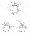
- Fig. 3 shows an alternative arrangement in which the grain cart 22 has the same ground wheels 26, 28, 30, and 32 but that front wheels 26 and 28 include motors 60 and 62 respectively connected to and driving wheels 26 and 28.
- the arrangement shown in Fig. 3 provides front drive traction for grain cart 22 but a differential speed control allows a directional or steering input.
- the motors 60 and 62 are connected to the tractor 38 via connector unit 64 and central connector 66 through to tractor 38.
- the motors 46 and 48 may be electrical in nature, receiving a current input from an appropriate device mounted on tractor 38.
- the control input would thus be an electrical current input varying both the power and rpm at the wheels and providing a differential steering in the absence of a uniform rpm for each wheel. It is also possible for the motors 60 and 62 to be hydraulic so that they provide propulsive input to wheels 26 and 28 via the appropriate connector 64 and 66.
- the motors 60 and 62 may be hydraulic in which motor 60 and 62 respond to pressurized fluid to provide appropriate power and speed for the grain cart. This offers the advantage of simplicity in that the differential rpm of the front wheels is used for steering, thus, obviating the need for a separate steering assembly.
- the source of steering and propulsion inputs to the grain cart 22 is provided from a device 68 mounted in tractor 38.
- Device 68 may be an electrical generator with appropriate current input to the respective wheels to provide the steering and/or ground propulsion inputs or it may be a hydraulic pump connected to appropriate hydraulic motors through conduits so as to provide the equivalent ground speed and turning responses.
- the prime power for the unit 68 is provided by a PTO from the tractor 38 or other device.
- the tractor 38 contains an operator control input so that the operator of the tractor 38 can control, from his station significantly outboard of the lateral extent of harvesting mechanism 12, the speed and steering capability of grain cart 22 to cause it to closely follow the central chassis 16 of the combine 12.
- a significantly shorter unloading device such as auger 70 to be utilized to deliver grain from the grain tank 18 to the receptacle 24 of the grain cart 22.
- an alternative to the steering and propulsion inputs provided by device 68 on tractor 38 is a device 88 mounted on, and receiving prime power from the combine 10 and extending to the grain cart 22 through connector 90.
- the control of grain cart 22 is provided from the combine 10, either by direct operator inputs or with an appropriate interactive control maintaining the grain cart 22 at a given position relative to the central chassis 16.
- the grain cart can be controlled to nutate around the discharge end of the auger 70 so that harvested crop material is uniformly distributed in the grain receptacle 24.
- FIG. 4 there is shown one form of interconnection between the grain cart 22 and the tractor 38.
- a tongue 72 is pivotally connected to the front of grain cart 22 at 74 and has an appropriate connection 76 for connecting to the hitch of tractor 38 for towing in the usual fashion.
- Fig. 4 shows a flexible cable 78 providing an interconnection of either electrical or hydraulic conduits to the appropriate motors on grain cart 22 for steering and/or control of the forward rate of speed of the grain cart 22.
- the tongue 72 is disconnected from tractor 38 when grain is to be unloaded and the cable 78 played out so that the grain cart may be deployed to an operational position close to the central chassis 16 of the combine and lateral to the ground movement of tractor 38.
- the cable 78 may be configured so that it has a variable extension from tractor 38.
- the operator of tractor 38 can control the velocity and direction of grain cart 22 to place it in dynamic position adjacent the central chassis of the combine and enable an unloading mechanism 28 from combine 10 that is of minimal length.
- the grain cart 22 When the grain cart 22 is fully loaded, it is steered into fore and aft alignment with tractor 38 and the tongue 72 connected so as to provide standard towing of the grain cart to the next step in the process of distributing the crop material thus harvested.
- Fig. 5 shows an alternative arrangement in which a substantially rigid but pivotable tongue is used for a multitude of functions.
- a tongue having first and second telescoping hollow assemblies 79 and 80 respectively connected to pivot points 82 on tractor 38 and 84 on grain cart 22.
- the telescoping assemblies are hollow so that the control conduits 86, which ultimately connect to the appropriate wheels, can be extended through to provide a steering and propulsion control input from tractor 38 to the grain cart 22.
- the tongues 79 and 80 are telescoped and hollow, they provide mechanical protection for the lines running therethrough, whether they be electrical or hydraulic. In this case, the pivoting connections 82 and 84 remain connected to the tractor 38 and grain cart 22 respectively during the unloading operation.
- the grain cart 22 When an unloading operation is completed, the grain cart 22 is steered into a position directly behind the tractor to provide for towing of the grain cart 22 to the next step in the collection of crop material.
- the advantage of the arrangement in Fig. 5 is that there is always a positive mechanical connection between the tractor 38 and the grain cart 22 while still permitting lateral control of the velocity and steering for the grain cart 22.
- the arrangement described above provides a significant advantage when deployed with a harvesting mechanism of the size currently experienced in the art.
- the mechanism is simplified and inherently made more efficient.
- the use of hydraulic or electric motors for propelling the grain cart wheels provides a significant degree of flexibility while, at the same time, providing significant control inputs from a position lateral to the movement of the grain cart alongside the central chassis 16 of the combine 10.
Landscapes
- Life Sciences & Earth Sciences (AREA)
- Engineering & Computer Science (AREA)
- Mechanical Engineering (AREA)
- Soil Sciences (AREA)
- Environmental Sciences (AREA)
- Combines (AREA)
- Guiding Agricultural Machines (AREA)
Abstract
Description
- The present invention relates to agricultural harvesting machines and, more particularly, to devices for collecting crop materials as harvested.
- Mechanical agricultural harvesting equipment has existed for centuries but there is a continuing need to increase the efficiency of harvesting. This means that a particular machine should be able to harvest over a greater span of crop rows, whether it be crops like corn or soybeans and the like. Combines have been developed to the point where they are multipurpose and can be used for a variety of crop materials. The crop harvesting mechanism can extend laterally for significant distances. While this provides efficiency in the harvesting process, the material thus harvested and processed must be unloaded to mobile grain carts and then to other machines for delivery to the ultimate destination. The grain carts typically have a capacity up to 2-3 times the capacity for the grain tank in the combine. As a result, they have substantial weight and require a tractor or other vehicle transporting them to be substantially in line with the cart itself and have sufficient power. As a result, the lateral extension of the harvesting mechanism on the combine requires that a significantly elongated lateral unloading device be provided with the combine with its attendant problems of reliability and control. The reason for this is that the tractor is in front of the grain cart and the grain cart cannot be deployable significantly behind the combine mechanism.
-
DE 1 681 008 U describes a trailer with driven wheels. - What is needed in the art, therefore, is an efficient mechanism for unloading combines of substantial capacity that eliminates the need for extended and elongated lateral combine unloading devices.
- A self-propelled grain cart for use with an agricultural combine has a central chassis and laterally elongated harvesting mechanism. The grain cart includes a grain receptacle. A plurality of wheels are connected to the grain receptacle, with at least one of the wheels being steerable and at least one of the wheels being powered for ground movement of the grain cart in a given direction. An elongated connector is operatively connected at one end thereof to the at least one steerable wheel and at least one powered wheel, with the connector being deployable laterally relative to the given direction of ground movement for the grain cart. A device is connected to the opposite end of the elongated connector for supplying ground movement and steering inputs to the at least one wheel so that the grain cart can be deployed close to the central axis of the combine.
- The above-mentioned and other features and advantages of this invention, and the manner of attaining them, will become more apparent and the invention will be better understood by reference to the following description of embodiments of the invention taken in conjunction with the accompanying drawings, wherein:
-
Fig. 1 is a plan view of an agricultural crop unloading system including a grain cart embodying the present invention; -
Fig. 2 shows one form of steering and propulsion for the grain cart ofFig. 2 in schematic fashion; -
Fig. 3 shows another form of steering and propulsion for the grain cart ofFig. 1 ; -
Fig. 4 shows one form of a connector for steering and propulsion inputs for the grain cart ofFig. 1 ; and -
Fig. 5 shows another form of steering and connector for steering and control inputs of the grain cart ofFig. 1 . - Corresponding reference characters indicate corresponding parts throughout the several views. The exemplifications set out herein illustrate one embodiment of the invention and such exemplifications are not to be construed as limiting the scope of the invention in any manner.
- Referring now to the drawings, and more particularly to
Fig. 1 , there is shown a plan view of an agricultural harvesting system in accordance with the present invention. The agricultural harvesting system includes acombine 10 having a laterally extendingharvester mechanism 12 with acentral feeder housing 14 to acentral chassis 16 containing the prime mover and auxiliary equipment necessary to move and process whatever agricultural crop is harvested. The harvested crop material is delivered to agrain tank 18 and the waste is discharged viaoutlet 20 to the ground. As indicated above, thelateral harvesting mechanism 12 can reach significant lengths. This necessitates that when thegrain tank 18 on the combine is full, it must be unloaded to a transportable cart for delivery to the next stage of distribution for the agricultural crop material. Grain carts can achieve significant weight and capacity requirements such that it is required to tow the grain cart directly behind a tractor or other powered vehicle. With the laterally extendingharvesting mechanism 12, it is not possible, in the current state of the art, to provide a proper towing relationship between the tractor and the grain cart. As a result, the unloading mechanism extending from thegrain tank 18 must be of significant length. - In accordance with the present invention, a
grain cart 22 is provided that is capable of self-propulsion and steering control. Thegrain cart 22 includes agrain receptacle 24 mounted on an appropriate chassis and containing a plurality ofwheels grain cart 22 for ground movement. As illustrated inFig. 1 , atongue assembly 34 extends from an articulatedjoint 36 on the front of the grain cart and to an equivalent articulatedjoint 36 connected to atractor 38. As described in detail below, thegrain cart 22 is adapted to be self-propelled and controlled for movement remotely by operator inputs from a laterally positionedtractor 38. Furthermore, at least one of the wheels is adapted to provide a propulsive input to the cart for movement and at least one is configured to supply a steering input. A connector, which may be thetongue 34, extends to thetractor 38 so that operator inputs for steering and traction may be controlled from the tractor, which is positioned outboard of the end most portion of theharvesting mechanism 12. As described below, the inputs for propulsion and/or steering may be electrical or they may be hydraulic. -
Fig. 2 shows afirst grain cart 22 having theground wheels Fig. 2 , asteering mechanism wheels steering mechanism lines 44 to provide appropriate steering ofgrain cart 22. As illustrated inFig. 2 ,grain cart 22 is front steered and haspropulsion motors rear wheels propulsion motors tractor 38 viaconnections Fig. 2 are appropriately provided through the connector, which includeslines tractor 38, which is positioned laterally of thegrain cart 22. - The advantage of the arrangement shown in
Fig. 2 is that the rear traction input provides better propulsive power going up a hill. -
Fig. 3 shows an alternative arrangement in which thegrain cart 22 has thesame ground wheels front wheels motors wheels Fig. 3 provides front drive traction forgrain cart 22 but a differential speed control allows a directional or steering input. Again, themotors tractor 38 viaconnector unit 64 andcentral connector 66 through totractor 38. As in the case withFig. 2 , themotors tractor 38. If themotors motors wheels appropriate connector motors motor - Referring back to
Fig. 1 , the source of steering and propulsion inputs to thegrain cart 22 is provided from adevice 68 mounted intractor 38.Device 68 may be an electrical generator with appropriate current input to the respective wheels to provide the steering and/or ground propulsion inputs or it may be a hydraulic pump connected to appropriate hydraulic motors through conduits so as to provide the equivalent ground speed and turning responses. In either case, the prime power for theunit 68 is provided by a PTO from thetractor 38 or other device. Furthermore, thetractor 38 contains an operator control input so that the operator of thetractor 38 can control, from his station significantly outboard of the lateral extent ofharvesting mechanism 12, the speed and steering capability ofgrain cart 22 to cause it to closely follow thecentral chassis 16 of thecombine 12. This, in turn, enables a significantly shorter unloading device such as auger 70 to be utilized to deliver grain from thegrain tank 18 to thereceptacle 24 of thegrain cart 22. As shown in dashed lines inFig. 1 , an alternative to the steering and propulsion inputs provided bydevice 68 ontractor 38 is adevice 88 mounted on, and receiving prime power from thecombine 10 and extending to thegrain cart 22 throughconnector 90. In this case, the control ofgrain cart 22 is provided from thecombine 10, either by direct operator inputs or with an appropriate interactive control maintaining thegrain cart 22 at a given position relative to thecentral chassis 16. For example the grain cart can be controlled to nutate around the discharge end of the auger 70 so that harvested crop material is uniformly distributed in thegrain receptacle 24. - Referring to
Fig. 4 , there is shown one form of interconnection between thegrain cart 22 and thetractor 38. Atongue 72 is pivotally connected to the front ofgrain cart 22 at 74 and has anappropriate connection 76 for connecting to the hitch oftractor 38 for towing in the usual fashion. In addition,Fig. 4 shows aflexible cable 78 providing an interconnection of either electrical or hydraulic conduits to the appropriate motors ongrain cart 22 for steering and/or control of the forward rate of speed of thegrain cart 22. In the arrangement shown inFig. 4 , thetongue 72 is disconnected fromtractor 38 when grain is to be unloaded and thecable 78 played out so that the grain cart may be deployed to an operational position close to thecentral chassis 16 of the combine and lateral to the ground movement oftractor 38. It is also possible that thecable 78 may be configured so that it has a variable extension fromtractor 38. As such, the operator oftractor 38 can control the velocity and direction ofgrain cart 22 to place it in dynamic position adjacent the central chassis of the combine and enable anunloading mechanism 28 fromcombine 10 that is of minimal length. When thegrain cart 22 is fully loaded, it is steered into fore and aft alignment withtractor 38 and thetongue 72 connected so as to provide standard towing of the grain cart to the next step in the process of distributing the crop material thus harvested. -
Fig. 5 shows an alternative arrangement in which a substantially rigid but pivotable tongue is used for a multitude of functions. In this figure, a tongue having first and second telescopinghollow assemblies points 82 ontractor grain cart 22. The telescoping assemblies are hollow so that thecontrol conduits 86, which ultimately connect to the appropriate wheels, can be extended through to provide a steering and propulsion control input fromtractor 38 to thegrain cart 22. Because thetongues pivoting connections tractor 38 andgrain cart 22 respectively during the unloading operation. When an unloading operation is completed, thegrain cart 22 is steered into a position directly behind the tractor to provide for towing of thegrain cart 22 to the next step in the collection of crop material. The advantage of the arrangement inFig. 5 is that there is always a positive mechanical connection between thetractor 38 and thegrain cart 22 while still permitting lateral control of the velocity and steering for thegrain cart 22. - It should be apparent to those skilled in the art that the connector arrangements for both electrical and hydraulic inputs may be utilized for control from the
combine 10. - The arrangement described above provides a significant advantage when deployed with a harvesting mechanism of the size currently experienced in the art. By enabling a relatively short unloading auger for the grain tank and the combine, the mechanism is simplified and inherently made more efficient. The use of hydraulic or electric motors for propelling the grain cart wheels provides a significant degree of flexibility while, at the same time, providing significant control inputs from a position lateral to the movement of the grain cart alongside the
central chassis 16 of thecombine 10.
Claims (15)
- A self-propelled grain cart (22) for use with an agricultural combine (10) having a central chassis (16) and laterally elongated harvesting mechanism (12), said cart (22) comprising:a grain receptacle (24);a plurality of wheels (26-32) connected to said grain cart (22), at least one of said wheels (26, 28) being steerable and at least one of said wheels (30,32) being powered for ground movement of said grain cart (22) in a given direction;an elongated connector operatively connected at one end thereof to said at least one steerable wheel (26, 28) and at least one powered wheel (26, 28, 30, 32), said connector being deployable laterally relative to the said given direction of ground movement for said grain cart (22); andcharacterized by a device connected to an opposite end of said elongated connector for supplying ground movement and steering inputs to said at least one wheel (26-32), whereby said grain cart (22) can be deployed close to the central chassis (16) of said combine (10).
- The self-propelled grain cart (22) as claimed in claim 1, wherein said elongated connector is flexible.
- The self-propelled grain cart (22) of claim 1, wherein the connector includes a telescoping tongue (34) pivotable on said grain cart (22).
- The self-propelled grain cart (22) as claimed in claim 3, wherein said tongue (34) protects said flexible connector.
- The self-propelled grain cart (22) as claimed in claim 1, further comprising electric motors (46, 48, 60, 62) connected to at least one of said wheels (26, 28, 30, 32), wherein said connector supplies electrical inputs to said motors (46, 48, 60, 62).
- The self-propelled grain cart (22) as claimed in claim 3, further comprising hydraulic motors (46, 48, 60, 62) connected to said at least one of said wheels (26, 28, 30, 32) and wherein said connector supplies hydraulic fluid to operate said motor (46, 48, 60, 62).
- The self-propelled grain cart (2) as claimed in claim 6, wherein said tongue (34) is hollow and said hydraulic lines extend through said hollow tongue (34) for protection.
- The self-propelled grain cart (22) as claimed in claim 1, wherein said front wheels (26, 28) of said cart (22) are steerable.
- The self-propelled grain cart (22) as claimed in claim 8, wherein said rear wheels (30, 32) are powered.
- The self-propelled grain cart (22) as claimed in claim 1, wherein said front wheels (26, 28) are differentially powered to provide a steering and propulsion input thereto.
- An agricultural crop unloading system for use with an agricultural combine (10) having a central chassis (16) and laterally elongated harvesting mechanism (12), said crop unloading system comprising a self-propelled agricultural vehicle (38) having a prime mover and capable of operator-controlled ground movement and supplying extra power and a grain cart (22) according to one of the preceding claims.
- The agricultural crop unloading system of claim 11, wherein said tongue (34) is telescoping between said grain receptacle and said agricultural vehicle (38).
- The agricultural crop unloading system of claim 11, further comprising an electrical motor (46, 48, 60, 62) connected to said at least one of said wheels (26, 28, 30, 32) on said grain cart (22) and wherein said agricultural vehicle (38) provides an electrical source for said electrical motor (46, 48, 60, 62) for driving said wheels (26, 28, 30, 32).
- The agricultural crop unloading system of claim 11, further comprising a hydraulic motor (46, 48, 60, 62) connected to said at least one of said wheels (26, 28, 30, 32) on said grain cart (22) and wherein said connector supplies hydraulic fluid to said motor (46, 48, 60, 62) and said agricultural vehicle (38) provides the source of said hydraulic fluid.
- The agricultural crop unloading system of claim 14, wherein said tongue (34) is connectable between said grain cart (22) and said agricultural vehicle (38) and hollow and said hydraulic lines extend therethrough for protection.
Applications Claiming Priority (1)
| Application Number | Priority Date | Filing Date | Title |
|---|---|---|---|
| US13/186,791 US8544574B2 (en) | 2011-07-20 | 2011-07-20 | Grain cart capable of self-propulsion |
Publications (2)
| Publication Number | Publication Date |
|---|---|
| EP2548429A1 true EP2548429A1 (en) | 2013-01-23 |
| EP2548429B1 EP2548429B1 (en) | 2016-02-03 |
Family
ID=46395488
Family Applications (1)
| Application Number | Title | Priority Date | Filing Date |
|---|---|---|---|
| EP12173081.6A Active EP2548429B1 (en) | 2011-07-20 | 2012-06-22 | Grain cart |
Country Status (4)
| Country | Link |
|---|---|
| US (1) | US8544574B2 (en) |
| EP (1) | EP2548429B1 (en) |
| AU (1) | AU2012205196A1 (en) |
| BR (1) | BR102012018007A2 (en) |
Cited By (1)
| Publication number | Priority date | Publication date | Assignee | Title |
|---|---|---|---|---|
| WO2015173073A1 (en) * | 2014-05-15 | 2015-11-19 | Cnh Industrial Belgium Nv | Harvesting method using unmanned agricultural work vehicles |
Families Citing this family (15)
| Publication number | Priority date | Publication date | Assignee | Title |
|---|---|---|---|---|
| US9037346B2 (en) | 2011-09-23 | 2015-05-19 | Deere & Company | Steering control for vehicle trains |
| US10104825B2 (en) * | 2012-09-06 | 2018-10-23 | Cnh Industrial America Llc | Pull frame for an agricultural implement |
| US9781873B2 (en) * | 2014-11-19 | 2017-10-10 | Cnh Industrial America Llc | Agricultural implement having power assist carrier wheels |
| US9706701B2 (en) * | 2014-11-19 | 2017-07-18 | Cnh Industrial America Llc | Agricultural implement having power assist wing wheels |
| US9675008B1 (en) | 2016-02-29 | 2017-06-13 | Cnh Industrial America Llc | Unloading arrangement for agricultural harvesting vehicles |
| US9809956B1 (en) | 2016-05-31 | 2017-11-07 | Deere & Company | Multi-vehicle coordinated grade control system |
| US10542676B2 (en) | 2016-06-10 | 2020-01-28 | Unverferth Manufacturing Company, Inc. | Grain cart with folding auger |
| US10351172B2 (en) | 2017-02-28 | 2019-07-16 | Brandt Agricultural Products Ltd. | Tandem steering for a grain cart |
| US10377290B2 (en) | 2017-02-28 | 2019-08-13 | Brandt Agricultural Products Ltd. | Spout autorotate for a grain cart |
| US10278328B2 (en) | 2017-02-28 | 2019-05-07 | Brandt Agricultural Products Ltd. | Grain cart with automatic unloading of a predetermined weight of crop material |
| US10988193B2 (en) | 2018-02-16 | 2021-04-27 | Deere & Company | Disconnectable work implement drive system |
| US11052769B2 (en) | 2019-02-25 | 2021-07-06 | Deere & Company | Traction control system and method of controlling a traction motor |
| US11872885B2 (en) | 2019-10-31 | 2024-01-16 | Deere & Company | Trailing vehicle traction control system with force increase control |
| US20240308824A1 (en) * | 2022-02-04 | 2024-09-19 | Fq Ip Ab | Navigator interface |
| US12239052B2 (en) | 2022-07-28 | 2025-03-04 | Deere & Company | Control system facilitating unloading during crop breakthrough harvesting |
Citations (6)
| Publication number | Priority date | Publication date | Assignee | Title |
|---|---|---|---|---|
| GB212950A (en) * | 1923-03-31 | 1925-09-18 | Adolf Heise | Improvements in and relating to devices for coupling trailers to tractors |
| US1555171A (en) * | 1924-07-02 | 1925-09-29 | Ross H Martyn | Vehicle steering and towing device |
| US2544925A (en) * | 1948-11-16 | 1951-03-13 | Int Harvester Co | Hitch for joining harvester and a wagon to a tractor |
| DE1681008U (en) | 1954-02-11 | 1954-08-05 | Friedrich Heidel | DEVICE FOR DRIVING A TRAILER. |
| US20090032273A1 (en) * | 2007-08-02 | 2009-02-05 | Klaus Hahn | Implement/vehicle steering control system and method |
| US20100326746A1 (en) * | 2009-06-25 | 2010-12-30 | Deere And Company | Drive quad module |
Family Cites Families (30)
| Publication number | Priority date | Publication date | Assignee | Title |
|---|---|---|---|---|
| US1695522A (en) * | 1923-02-03 | 1928-12-18 | Int Harvester Co | Power-drive grain binder |
| US1832051A (en) * | 1927-04-06 | 1931-11-17 | Int Harvester Co | Driving means |
| US2363897A (en) * | 1943-05-17 | 1944-11-28 | Deere & Co | Implement attachment for tractors |
| US2427824A (en) * | 1943-07-23 | 1947-09-23 | Avco Mfg Corp | Power transmission shafting and support therefor |
| US2494388A (en) * | 1944-06-16 | 1950-01-10 | Case Co J I | Combination harvesting and ensilage cutting machine |
| US2429492A (en) * | 1945-03-09 | 1947-10-21 | Allis Chalmers Mfg Co | Implement draft device and shaft support thereon |
| US2769384A (en) * | 1953-11-16 | 1956-11-06 | Int Harvester Co | Plow |
| US3336052A (en) * | 1965-08-13 | 1967-08-15 | Int Harvester Co | Side draft control mechanism |
| US3523410A (en) * | 1968-04-26 | 1970-08-11 | Clyde L Taylor | Apparatus for mowing,conditioning and windrowing forage |
| US4050598A (en) * | 1975-04-14 | 1977-09-27 | Farmhand, Inc. | Bale wagon |
| US4076137A (en) * | 1976-08-05 | 1978-02-28 | Rudolph L. Lowell | Large round bale handling apparatus |
| US4227844A (en) * | 1979-01-16 | 1980-10-14 | Love Phillip W | Apparatus for lifting and transporting large bales of material |
| US5579228A (en) * | 1991-05-21 | 1996-11-26 | University Of Utah Research Foundation | Steering control system for trailers |
| US5730572A (en) * | 1997-01-07 | 1998-03-24 | Scheuren; Duane L. | Bale handling carrier |
| US5904365A (en) * | 1997-09-11 | 1999-05-18 | Dillon; Ben N. | Combine with powered and steerable grain trailer |
| US6019562A (en) * | 1997-10-21 | 2000-02-01 | Cheatham; Albert William | Bale loading system |
| US6668225B2 (en) * | 2000-11-29 | 2003-12-23 | Visteon Global Technologies, Inc. | Trailer control system |
| CA2406155C (en) * | 2002-10-02 | 2008-02-19 | Schulte Industries Ltd. | Offset arm for towing rotary mowers and the like |
| US7142150B2 (en) | 2004-12-15 | 2006-11-28 | Deere & Company | Method and system for detecting an object using a composite evidence grid |
| US7266477B2 (en) | 2005-06-22 | 2007-09-04 | Deere & Company | Method and system for sensor signal fusion |
| US7743859B2 (en) | 2006-02-03 | 2010-06-29 | Magna Powertrain Usa, Inc. | Hybrid drivetrains for trailers |
| DE102007009666A1 (en) * | 2007-02-22 | 2008-08-28 | Carl Zeiss Microimaging Gmbh | Arrangement for filling a container with bulk material |
| DE102007016670A1 (en) * | 2007-04-04 | 2008-10-09 | Claas Selbstfahrende Erntemaschinen Gmbh | Self-propelled agricultural harvester with controllable transfer device |
| US7913782B1 (en) * | 2007-08-17 | 2011-03-29 | Polaris Industries Inc. | Pull behind unit for use with a self-propelled unit |
| DE102008002006A1 (en) * | 2008-05-27 | 2009-12-03 | Deere & Company, Moline | Control arrangement for controlling the transfer of agricultural crop from a harvester to a transport vehicle |
| US8195358B2 (en) | 2008-09-11 | 2012-06-05 | Deere & Company | Multi-vehicle high integrity perception |
| US9188980B2 (en) | 2008-09-11 | 2015-11-17 | Deere & Company | Vehicle with high integrity perception system |
| US8478493B2 (en) | 2008-09-11 | 2013-07-02 | Deere & Company | High integrity perception program |
| US8437901B2 (en) | 2008-10-15 | 2013-05-07 | Deere & Company | High integrity coordination for multiple off-road vehicles |
| US8639408B2 (en) | 2008-10-15 | 2014-01-28 | Deere & Company | High integrity coordination system for multiple off-road vehicles |
-
2011
- 2011-07-20 US US13/186,791 patent/US8544574B2/en active Active
-
2012
- 2012-06-22 EP EP12173081.6A patent/EP2548429B1/en active Active
- 2012-07-17 AU AU2012205196A patent/AU2012205196A1/en not_active Abandoned
- 2012-07-19 BR BRBR102012018007-3A patent/BR102012018007A2/en not_active Application Discontinuation
Patent Citations (6)
| Publication number | Priority date | Publication date | Assignee | Title |
|---|---|---|---|---|
| GB212950A (en) * | 1923-03-31 | 1925-09-18 | Adolf Heise | Improvements in and relating to devices for coupling trailers to tractors |
| US1555171A (en) * | 1924-07-02 | 1925-09-29 | Ross H Martyn | Vehicle steering and towing device |
| US2544925A (en) * | 1948-11-16 | 1951-03-13 | Int Harvester Co | Hitch for joining harvester and a wagon to a tractor |
| DE1681008U (en) | 1954-02-11 | 1954-08-05 | Friedrich Heidel | DEVICE FOR DRIVING A TRAILER. |
| US20090032273A1 (en) * | 2007-08-02 | 2009-02-05 | Klaus Hahn | Implement/vehicle steering control system and method |
| US20100326746A1 (en) * | 2009-06-25 | 2010-12-30 | Deere And Company | Drive quad module |
Cited By (2)
| Publication number | Priority date | Publication date | Assignee | Title |
|---|---|---|---|---|
| WO2015173073A1 (en) * | 2014-05-15 | 2015-11-19 | Cnh Industrial Belgium Nv | Harvesting method using unmanned agricultural work vehicles |
| BE1022142B1 (en) * | 2014-05-15 | 2016-02-19 | Cnh Industrial Belgium Nv | METHOD FOR HARVESTING M.B.V. UNMANNED WORK VEHICLES FOR AGRICULTURE. |
Also Published As
| Publication number | Publication date |
|---|---|
| BR102012018007A2 (en) | 2013-07-02 |
| AU2012205196A1 (en) | 2013-02-07 |
| US20130020138A1 (en) | 2013-01-24 |
| EP2548429B1 (en) | 2016-02-03 |
| US8544574B2 (en) | 2013-10-01 |
Similar Documents
| Publication | Publication Date | Title |
|---|---|---|
| EP2548429B1 (en) | Grain cart | |
| EP2548431B1 (en) | Material transfer system | |
| US9320197B2 (en) | Self-propelled agricultural harvesting machine having a crop attachment which is pivotable about a vertical axis | |
| US20130019580A1 (en) | Bidirectional harvesting system | |
| US10028442B1 (en) | Self-propelled, close-coupled, autonomous grain cart | |
| WO2014046685A1 (en) | Bidirectional harvesting system | |
| EP3038450B1 (en) | Articulated rider collection assembly | |
| US8602135B2 (en) | Drive quad module | |
| EP3057398A1 (en) | Autonomous systems, methods, and apparatus for ag based operations | |
| US9420744B2 (en) | Hydraulic system for collecting crop grain and crop residue in a single pass | |
| BR102012024316A2 (en) | SELF-PROPELLED AGRICULTURAL HARVESTING MACHINE | |
| EP1347676A1 (en) | Hydraulic drive line and hitching assembly for pull-type implement | |
| US4256431A (en) | Self-driven forage harvester | |
| US20020069629A1 (en) | Hydraulic drive line and hitching assembly for pull-type implements | |
| US20180362098A1 (en) | Self-propelled multipurpose vehicle | |
| EP2087785B1 (en) | Articulated transport arrangement for a windrower with a cutting platform | |
| US20170086367A1 (en) | Crop Harvesting Machine with a Header Separable from a Tractor | |
| US11414142B1 (en) | Battery-operated electric hydrostatic utility tractor | |
| CN206808083U (en) | Agricultural operation car | |
| US20100016046A1 (en) | Flexible unloading tube | |
| US8821228B1 (en) | Dual bin combine system | |
| US20240407296A1 (en) | Novel towing system and method | |
| US20260007094A1 (en) | Modular agricultural header | |
| WO2024213947A1 (en) | Crop harvesters | |
| US20230010916A1 (en) | Self-Propelled Agricultural Work Machine |
Legal Events
| Date | Code | Title | Description |
|---|---|---|---|
| PUAI | Public reference made under article 153(3) epc to a published international application that has entered the european phase |
Free format text: ORIGINAL CODE: 0009012 |
|
| AK | Designated contracting states |
Kind code of ref document: A1 Designated state(s): AL AT BE BG CH CY CZ DE DK EE ES FI FR GB GR HR HU IE IS IT LI LT LU LV MC MK MT NL NO PL PT RO RS SE SI SK SM TR |
|
| AX | Request for extension of the european patent |
Extension state: BA ME |
|
| 17P | Request for examination filed |
Effective date: 20130723 |
|
| RBV | Designated contracting states (corrected) |
Designated state(s): AL AT BE BG CH CY CZ DE DK EE ES FI FR GB GR HR HU IE IS IT LI LT LU LV MC MK MT NL NO PL PT RO RS SE SI SK SM TR |
|
| 17Q | First examination report despatched |
Effective date: 20140131 |
|
| GRAP | Despatch of communication of intention to grant a patent |
Free format text: ORIGINAL CODE: EPIDOSNIGR1 |
|
| INTG | Intention to grant announced |
Effective date: 20150921 |
|
| RAP1 | Party data changed (applicant data changed or rights of an application transferred) |
Owner name: DEERE & COMPANY |
|
| GRAS | Grant fee paid |
Free format text: ORIGINAL CODE: EPIDOSNIGR3 |
|
| GRAA | (expected) grant |
Free format text: ORIGINAL CODE: 0009210 |
|
| RIN1 | Information on inventor provided before grant (corrected) |
Inventor name: ANDERSON, NOEL WAYNE Inventor name: SHEIDLER, ALAN D Inventor name: FEGLEY, MICHAEL D |
|
| AK | Designated contracting states |
Kind code of ref document: B1 Designated state(s): AL AT BE BG CH CY CZ DE DK EE ES FI FR GB GR HR HU IE IS IT LI LT LU LV MC MK MT NL NO PL PT RO RS SE SI SK SM TR |
|
| REG | Reference to a national code |
Ref country code: GB Ref legal event code: FG4D |
|
| REG | Reference to a national code |
Ref country code: AT Ref legal event code: REF Ref document number: 773215 Country of ref document: AT Kind code of ref document: T Effective date: 20160215 Ref country code: CH Ref legal event code: EP |
|
| REG | Reference to a national code |
Ref country code: IE Ref legal event code: FG4D |
|
| REG | Reference to a national code |
Ref country code: DE Ref legal event code: R096 Ref document number: 602012014300 Country of ref document: DE |
|
| REG | Reference to a national code |
Ref country code: LT Ref legal event code: MG4D Ref country code: NL Ref legal event code: MP Effective date: 20160203 |
|
| REG | Reference to a national code |
Ref country code: AT Ref legal event code: MK05 Ref document number: 773215 Country of ref document: AT Kind code of ref document: T Effective date: 20160203 |
|
| PG25 | Lapsed in a contracting state [announced via postgrant information from national office to epo] |
Ref country code: ES Free format text: LAPSE BECAUSE OF FAILURE TO SUBMIT A TRANSLATION OF THE DESCRIPTION OR TO PAY THE FEE WITHIN THE PRESCRIBED TIME-LIMIT Effective date: 20160203 Ref country code: HR Free format text: LAPSE BECAUSE OF FAILURE TO SUBMIT A TRANSLATION OF THE DESCRIPTION OR TO PAY THE FEE WITHIN THE PRESCRIBED TIME-LIMIT Effective date: 20160203 Ref country code: GR Free format text: LAPSE BECAUSE OF FAILURE TO SUBMIT A TRANSLATION OF THE DESCRIPTION OR TO PAY THE FEE WITHIN THE PRESCRIBED TIME-LIMIT Effective date: 20160504 Ref country code: FI Free format text: LAPSE BECAUSE OF FAILURE TO SUBMIT A TRANSLATION OF THE DESCRIPTION OR TO PAY THE FEE WITHIN THE PRESCRIBED TIME-LIMIT Effective date: 20160203 Ref country code: NO Free format text: LAPSE BECAUSE OF FAILURE TO SUBMIT A TRANSLATION OF THE DESCRIPTION OR TO PAY THE FEE WITHIN THE PRESCRIBED TIME-LIMIT Effective date: 20160503 Ref country code: IT Free format text: LAPSE BECAUSE OF FAILURE TO SUBMIT A TRANSLATION OF THE DESCRIPTION OR TO PAY THE FEE WITHIN THE PRESCRIBED TIME-LIMIT Effective date: 20160203 |
|
| PG25 | Lapsed in a contracting state [announced via postgrant information from national office to epo] |
Ref country code: PL Free format text: LAPSE BECAUSE OF FAILURE TO SUBMIT A TRANSLATION OF THE DESCRIPTION OR TO PAY THE FEE WITHIN THE PRESCRIBED TIME-LIMIT Effective date: 20160203 Ref country code: RS Free format text: LAPSE BECAUSE OF FAILURE TO SUBMIT A TRANSLATION OF THE DESCRIPTION OR TO PAY THE FEE WITHIN THE PRESCRIBED TIME-LIMIT Effective date: 20160203 Ref country code: LV Free format text: LAPSE BECAUSE OF FAILURE TO SUBMIT A TRANSLATION OF THE DESCRIPTION OR TO PAY THE FEE WITHIN THE PRESCRIBED TIME-LIMIT Effective date: 20160203 Ref country code: NL Free format text: LAPSE BECAUSE OF FAILURE TO SUBMIT A TRANSLATION OF THE DESCRIPTION OR TO PAY THE FEE WITHIN THE PRESCRIBED TIME-LIMIT Effective date: 20160203 Ref country code: SE Free format text: LAPSE BECAUSE OF FAILURE TO SUBMIT A TRANSLATION OF THE DESCRIPTION OR TO PAY THE FEE WITHIN THE PRESCRIBED TIME-LIMIT Effective date: 20160203 Ref country code: IS Free format text: LAPSE BECAUSE OF FAILURE TO SUBMIT A TRANSLATION OF THE DESCRIPTION OR TO PAY THE FEE WITHIN THE PRESCRIBED TIME-LIMIT Effective date: 20160603 Ref country code: AT Free format text: LAPSE BECAUSE OF FAILURE TO SUBMIT A TRANSLATION OF THE DESCRIPTION OR TO PAY THE FEE WITHIN THE PRESCRIBED TIME-LIMIT Effective date: 20160203 Ref country code: LT Free format text: LAPSE BECAUSE OF FAILURE TO SUBMIT A TRANSLATION OF THE DESCRIPTION OR TO PAY THE FEE WITHIN THE PRESCRIBED TIME-LIMIT Effective date: 20160203 Ref country code: PT Free format text: LAPSE BECAUSE OF FAILURE TO SUBMIT A TRANSLATION OF THE DESCRIPTION OR TO PAY THE FEE WITHIN THE PRESCRIBED TIME-LIMIT Effective date: 20160603 |
|
| PG25 | Lapsed in a contracting state [announced via postgrant information from national office to epo] |
Ref country code: EE Free format text: LAPSE BECAUSE OF FAILURE TO SUBMIT A TRANSLATION OF THE DESCRIPTION OR TO PAY THE FEE WITHIN THE PRESCRIBED TIME-LIMIT Effective date: 20160203 Ref country code: DK Free format text: LAPSE BECAUSE OF FAILURE TO SUBMIT A TRANSLATION OF THE DESCRIPTION OR TO PAY THE FEE WITHIN THE PRESCRIBED TIME-LIMIT Effective date: 20160203 |
|
| REG | Reference to a national code |
Ref country code: DE Ref legal event code: R097 Ref document number: 602012014300 Country of ref document: DE |
|
| PG25 | Lapsed in a contracting state [announced via postgrant information from national office to epo] |
Ref country code: RO Free format text: LAPSE BECAUSE OF FAILURE TO SUBMIT A TRANSLATION OF THE DESCRIPTION OR TO PAY THE FEE WITHIN THE PRESCRIBED TIME-LIMIT Effective date: 20160203 Ref country code: SK Free format text: LAPSE BECAUSE OF FAILURE TO SUBMIT A TRANSLATION OF THE DESCRIPTION OR TO PAY THE FEE WITHIN THE PRESCRIBED TIME-LIMIT Effective date: 20160203 Ref country code: SM Free format text: LAPSE BECAUSE OF FAILURE TO SUBMIT A TRANSLATION OF THE DESCRIPTION OR TO PAY THE FEE WITHIN THE PRESCRIBED TIME-LIMIT Effective date: 20160203 Ref country code: CZ Free format text: LAPSE BECAUSE OF FAILURE TO SUBMIT A TRANSLATION OF THE DESCRIPTION OR TO PAY THE FEE WITHIN THE PRESCRIBED TIME-LIMIT Effective date: 20160203 |
|
| PLBE | No opposition filed within time limit |
Free format text: ORIGINAL CODE: 0009261 |
|
| STAA | Information on the status of an ep patent application or granted ep patent |
Free format text: STATUS: NO OPPOSITION FILED WITHIN TIME LIMIT |
|
| PG25 | Lapsed in a contracting state [announced via postgrant information from national office to epo] |
Ref country code: BE Free format text: LAPSE BECAUSE OF FAILURE TO SUBMIT A TRANSLATION OF THE DESCRIPTION OR TO PAY THE FEE WITHIN THE PRESCRIBED TIME-LIMIT Effective date: 20160203 |
|
| 26N | No opposition filed |
Effective date: 20161104 |
|
| PG25 | Lapsed in a contracting state [announced via postgrant information from national office to epo] |
Ref country code: MC Free format text: LAPSE BECAUSE OF FAILURE TO SUBMIT A TRANSLATION OF THE DESCRIPTION OR TO PAY THE FEE WITHIN THE PRESCRIBED TIME-LIMIT Effective date: 20160203 |
|
| REG | Reference to a national code |
Ref country code: CH Ref legal event code: PL |
|
| PG25 | Lapsed in a contracting state [announced via postgrant information from national office to epo] |
Ref country code: BG Free format text: LAPSE BECAUSE OF FAILURE TO SUBMIT A TRANSLATION OF THE DESCRIPTION OR TO PAY THE FEE WITHIN THE PRESCRIBED TIME-LIMIT Effective date: 20160503 Ref country code: SI Free format text: LAPSE BECAUSE OF FAILURE TO SUBMIT A TRANSLATION OF THE DESCRIPTION OR TO PAY THE FEE WITHIN THE PRESCRIBED TIME-LIMIT Effective date: 20160203 |
|
| GBPC | Gb: european patent ceased through non-payment of renewal fee |
Effective date: 20160622 |
|
| REG | Reference to a national code |
Ref country code: IE Ref legal event code: MM4A |
|
| REG | Reference to a national code |
Ref country code: FR Ref legal event code: ST Effective date: 20170228 |
|
| PG25 | Lapsed in a contracting state [announced via postgrant information from national office to epo] |
Ref country code: CH Free format text: LAPSE BECAUSE OF NON-PAYMENT OF DUE FEES Effective date: 20160630 Ref country code: LI Free format text: LAPSE BECAUSE OF NON-PAYMENT OF DUE FEES Effective date: 20160630 Ref country code: FR Free format text: LAPSE BECAUSE OF NON-PAYMENT OF DUE FEES Effective date: 20160630 |
|
| PG25 | Lapsed in a contracting state [announced via postgrant information from national office to epo] |
Ref country code: GB Free format text: LAPSE BECAUSE OF NON-PAYMENT OF DUE FEES Effective date: 20160622 Ref country code: IE Free format text: LAPSE BECAUSE OF NON-PAYMENT OF DUE FEES Effective date: 20160622 |
|
| PG25 | Lapsed in a contracting state [announced via postgrant information from national office to epo] |
Ref country code: HU Free format text: LAPSE BECAUSE OF FAILURE TO SUBMIT A TRANSLATION OF THE DESCRIPTION OR TO PAY THE FEE WITHIN THE PRESCRIBED TIME-LIMIT; INVALID AB INITIO Effective date: 20120622 Ref country code: CY Free format text: LAPSE BECAUSE OF FAILURE TO SUBMIT A TRANSLATION OF THE DESCRIPTION OR TO PAY THE FEE WITHIN THE PRESCRIBED TIME-LIMIT Effective date: 20160203 |
|
| PG25 | Lapsed in a contracting state [announced via postgrant information from national office to epo] |
Ref country code: TR Free format text: LAPSE BECAUSE OF FAILURE TO SUBMIT A TRANSLATION OF THE DESCRIPTION OR TO PAY THE FEE WITHIN THE PRESCRIBED TIME-LIMIT Effective date: 20160203 Ref country code: MK Free format text: LAPSE BECAUSE OF FAILURE TO SUBMIT A TRANSLATION OF THE DESCRIPTION OR TO PAY THE FEE WITHIN THE PRESCRIBED TIME-LIMIT Effective date: 20160203 Ref country code: MT Free format text: LAPSE BECAUSE OF NON-PAYMENT OF DUE FEES Effective date: 20160630 Ref country code: LU Free format text: LAPSE BECAUSE OF NON-PAYMENT OF DUE FEES Effective date: 20160622 |
|
| PG25 | Lapsed in a contracting state [announced via postgrant information from national office to epo] |
Ref country code: AL Free format text: LAPSE BECAUSE OF FAILURE TO SUBMIT A TRANSLATION OF THE DESCRIPTION OR TO PAY THE FEE WITHIN THE PRESCRIBED TIME-LIMIT Effective date: 20160203 |
|
| PGFP | Annual fee paid to national office [announced via postgrant information from national office to epo] |
Ref country code: DE Payment date: 20250521 Year of fee payment: 14 |